dart-agilent vapur interface manual - ionsense · dart-agilent vapur interface manual (si-300-a rev...
TRANSCRIPT

DART-Agilent Vapur Interface Manual
For Agilent TOF and Ion Trap Instruments
Rev 2
Document # 7.5.059
IonSense Inc.
999 Broadway
Suite 404
Saugus, MA 01906

DART-Agilent Vapur Interface Manual (SI-300-A Rev 2) 2
Copyright © 2005-2014 by IonSense Inc.
All rights reserved.
The information in this document has been carefully checked and is believed to be
reliable. However, no responsibility is assumed for inaccuracies. Statements in the
document not intended to create any warranty, expressed or implied. Specification and
performance characteristics of the hardware and software described in the manual may be
changed at any time without notice. IonSense Inc. reserves the right to make changes in
any product herein in order to improve reliability, design, or function. IonSense does not
assume any liability arising out of application or use of any product or circuit described
nor does it cover any license under its patent rights or the rights of others.
The apparatus and application of the apparatus described in this document is protected by
US Patent Number 6,949,741 and used under license; additional patents pending.
All trademarks are properties of their respective owners.

DART-Agilent Vapur Interface Manual (SI-300-A Rev 2) 3
This manual details the steps necessary to install a DART source on an Agilent
Instrument. It will focus on the Agilent TOF models, but these instructions are also
applicable for Agilent Ion Trap instruments as well.
Table of Contents
1. Diagram of the Agilent Source and Interface
2. Attaching the DART Vapur Flange to the Instrument
3. Setting the Source Type
a. For New Instruments
b. Old-Style Instruments
4. Optimal Parameters
5. Enabling Contact Closure
6. Calibrating the Agilent TOF with DART

DART-Agilent Vapur Interface Manual (SI-300-A Rev 2) 4
Diagram of the Agilent Source and Interface
All current Agilent sources have an “i-button” attached on the left side (as you are
looking down the capillary of the instrument). The dual ESI source shown below has an
i-button marked “11”.
Figure 1: Dual ESI source view
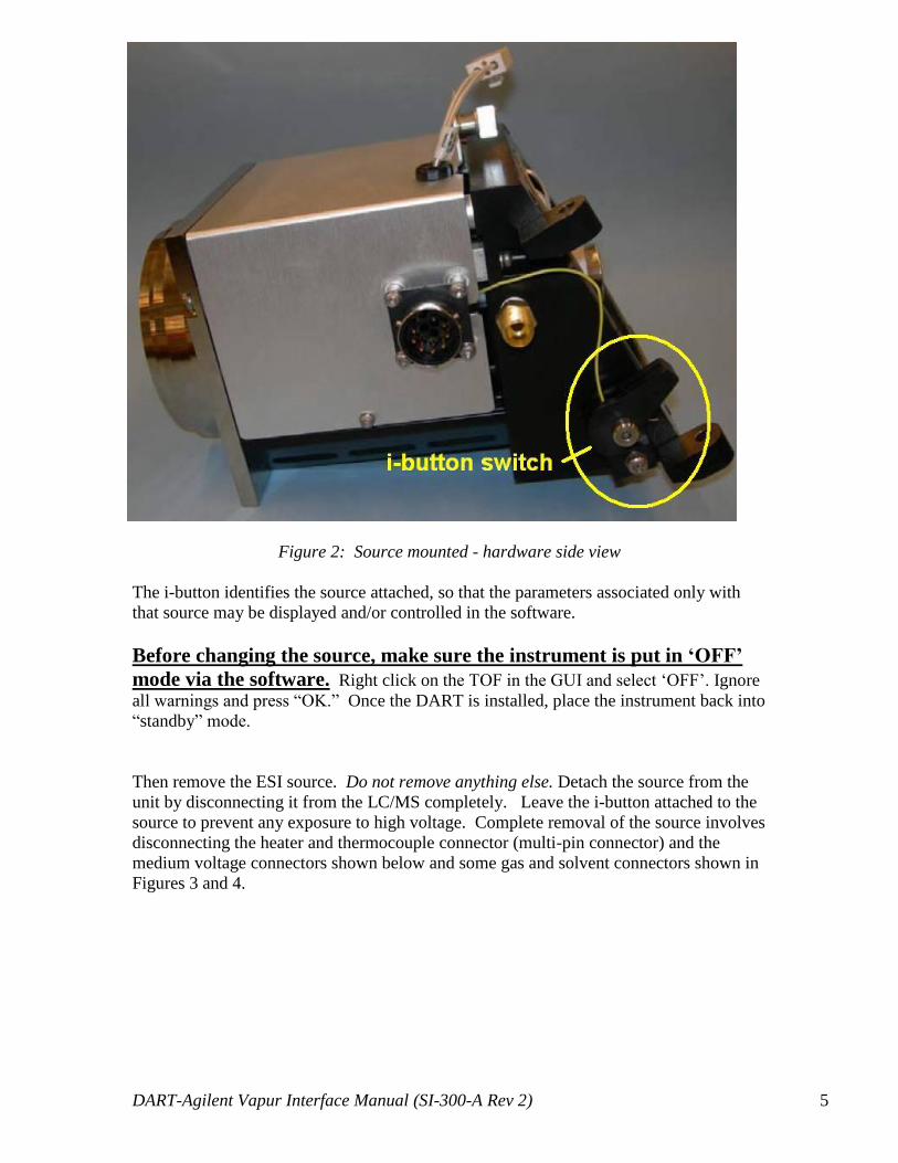
The desolvation chamber on the Agilent systems has an electronic reader that interprets
the information on the i-button. The reader is shown in the picture below at the right end
of the yellow wire in Figure 2.
DART-Agilent Vapur Interface Manual (SI-300-A Rev 2) 5
Figure 2: Source mounted - hardware side view
The i-button identifies the source attached, so that the parameters associated only with
that source may be displayed and/or controlled in the software.
Before changing the source, make sure the instrument is put in ‘OFF’
mode via the software. Right click on the TOF in the GUI and select ‘OFF’. Ignore
all warnings and press “OK.” Once the DART is installed, place the instrument back into
“standby” mode.
Then remove the ESI source. Do not remove anything else. Detach the source from the
unit by disconnecting it from the LC/MS completely. Leave the i-button attached to the
source to prevent any exposure to high voltage. Complete removal of the source involves
disconnecting the heater and thermocouple connector (multi-pin connector) and the
medium voltage connectors shown below and some gas and solvent connectors shown in
Figures 3 and 4.

DART-Agilent Vapur Interface Manual (SI-300-A Rev 2) 6
Figure 3: Multi-pin Connector leading to Agilent source
Figure 4: Medium voltage connector leading to Agilent source
DART-Agilent Vapur Interface Manual (SI-300-A Rev 2) 7
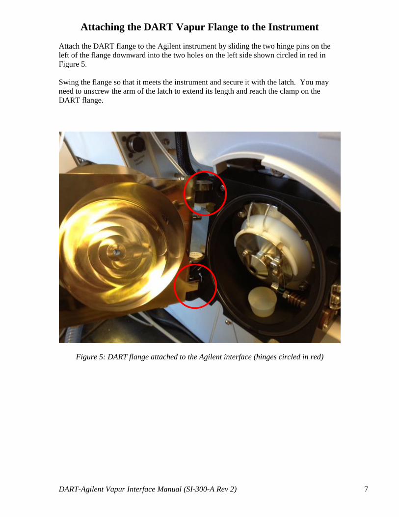
Attaching the DART Vapur Flange to the Instrument
Attach the DART flange to the Agilent instrument by sliding the two hinge pins on the
left of the flange downward into the two holes on the left side shown circled in red in
Figure 5.
Swing the flange so that it meets the instrument and secure it with the latch. You may
need to unscrew the arm of the latch to extend its length and reach the clamp on the
DART flange.
Figure 5: DART flange attached to the Agilent interface (hinges circled in red)

DART-Agilent Vapur Interface Manual (SI-300-A Rev 2) 8
Figure 6: Rubber stopper in place to create seal with interface (Agilent splash guard still
in place)
Insert the rubber stopper into the waste pumping port as shown in Figure 6 and remove
the Agilent splash guard (pictured below in Figure 7) before closing the Vapur Interface.
Note: If may be necessary to adjust the length of the Agilent clasp used to secure the
Vapur Interface to the front of the instrument. Make sure that the Vapur Interface makes
a good seal against the front of the instrument otherwise there will be vacuum instability.
Figure 7: Agilent splash guard removed

DART-Agilent Vapur Interface Manual (SI-300-A Rev 2) 9
Figure 8: Vapur Interface fully mounted on Agilent MS
Inserting the Ceramic Ion Transfer Tube into the Vapur Interface
Remove the Swagelok nut from the front of the Vapur Interface and insert the ceramic
ion transfer tube into the interface. Secure the ceramic tube with one of the provided
graphite ferrules making sure to set a 2 mm gap inside the interface.
Make sure to set a 2 mm gap inside the Vapur Interface between the end of the ceramic
tube and the Agilent capillary inside the Vapur Interface.
This gap ensures that the excess helium gas will be evacuated and maintain proper
vacuum in the instrument.
Take care to attach the black rubber pumping line from diaphragm pump over the
barbed pumping port fitting on the side of the Vapur Interface.
Refer to the DART SVP Hardware and Network Installation Manual (pages 6-8) for
more specifics on interfacing the DART SVP source to the Vapur Interface.
IonSense website: (http://www.ionsense.com/manuals)

DART-Agilent Vapur Interface Manual (SI-300-A Rev 2) 10
Setting the Source Type
The source setting in the MassHunter software is most likely set to “ESI,” which is the
default setting if the system has not detected an i-button present.
Change the source type to “Dual-ESI”.
The capillary (in the case of ESI) is at high temperature. You can increase/decrease the
temp inside the MassHunter software window (shown below in Figure 9).
Figure 9: MassHunter Control program window
Optimal Parameters IonSense recommends using the following operational settings:
Capillary Voltage: ~1000V
Drying Gas: 8.5 L/min (Important to keep H2O cluster formation low)
Fragmentor Voltage: 150-175V
Octapole Voltage:
o 250V for masses above 100 Da
o 100V for masses below 100 Da
If “Dual-ESI is not an option: On older-version instruments, “Dual-ESI” is not an option in the software.
In this case:
1. Set the source type to “ESI”.
2. On the start button select:
Programs → Agilent- MassHunterWorkstation → Acquisition tools →
Instrument Configuration 3. Deselect LC
4. On the source button select "Do not wait for set-points to equilibrate"
Enter Dual-
ESI source

DART-Agilent Vapur Interface Manual (SI-300-A Rev 2) 11
Enabling Contact Closure
Figure 10: A) Contact closure “Remote” port on Agilent mass spectrometer
B) DART-SVP contact closure cable plugged in
1. Plug in the contact closure cable from your DART-SVP kit into the serial port
on the Agilent mass spectrometer that says “Remote” as shown in Figure 10.
Figure 11: Contact closure cable plugged into the DART-SVP controller
2. Plug the other end of the cable into the “Mass-Spec Interface” port on the
DART-SVP controller as shown in Figure 11.
A B

DART-Agilent Vapur Interface Manual (SI-300-A Rev 2) 12
DART SVP Software Settings for Contact Closure
Navigate in the DART SVP software
to the “Settings” page and click on
the “Contact Closure” button.
On the “Contact Closure” page
check to make sure that “Method
Start Signal” is selected “On”.
Navigate to the “Methods” page and
select the desired method. You can
“Edit” the method parameters or hit
“Start” to initiate the DART
sampling method, which will trigger
the mass spectrometer data
acquisition via contact closure.

DART-Agilent Vapur Interface Manual (SI-300-A Rev 2) 13
MassHunter Data Acquisition: Contact Closure Set-up
Figure 12: Worklist drop down menu
3. Click on the “Worklist” drop down menu and select “Worklist Run
Parameters…” as shown in Figure 12.

DART-Agilent Vapur Interface Manual (SI-300-A Rev 2) 14
Figure 13: Work List Parameters… Menu
4. Select “External Start” from the drop down menu for “Run Type” as shown
in Figure 13.
Figure 14: Worklist tab for sample queue
5. In the “Worklist” tab set up your sample name, method, data file, and sample
type and to begin your run.

DART-Agilent Vapur Interface Manual (SI-300-A Rev 2) 15
Calibrating the Agilent TOF with DART
Thanks to George Dubay of Duke University and Howard Sanford of Agilent
Technologies for their assistance with this section.
While a tune done with the ESI source will remain current with the DART, it is necessary
to calibrate the Agilent TOF with the DART before usage to ensure mass accuracy.
The critical factor for the calibration is ion stability. If the ion current is unstable during
calibration, the system destabilizes and the mass accuracy will drift significantly.
To ensure a stable ion current:
The ions used for calibration must be not too small or large: ~100-700 Da.
IonSense recommends PEG-600 as a calibration compound for achieving
these target ions.
Maintain the instrument vacuum at the lower reaches of 10-7
. At high
vacuum pressures (10-6
and lower), performance decreases. Also, the
vacuum should be relatively constant and not wildly fluctuating.
o To do this, it may be necessary to pull the DART source away
from the ceramic tube inlet so that the gap between the ceramic cap
and ceramic tube is ~8.5mm.
o When using IonSense experiment modules to introduce samples,
attach them to the rail in the position farther away from the API
inlet.
Target ion abundances for calibration ions should be in the range of 200-
500K. Greater abundances will lead to system instability.
It is recommended to use the Agilent instrument’s standard capillary
instead of the resistive-type capillary.

DART-Agilent Vapur Interface Manual (SI-300-A Rev 2) 16
Revision History
REV DCR # Description of Change Effective Date
1.0 43 Initial Release 11/11/2013
2.0 88 Changed distance on page 15 to
8.5mm from 8.5cm.
Removed part number of flange
from document, do not want to
have to update document if part
number changes
Corrected copyright date from 2012
to 2014
3/10/2014