dart e3 pointer handbook 2225 - kitamura …kitamuracomputers.net/downloads/userguides/buses/dennis...
TRANSCRIPT
Operation Guide
POINTER
Publication Number 2225 ~ Dart 4 & 6 cylinder/ PointerUsed on & up to Chassis No 7465 (not including 7375) ~ September 2003 (03/04)
3
Introduction
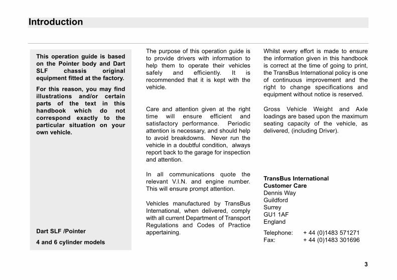
The purpose of this operation guide isto provide drivers with information tohelp them to operate their vehiclessafely and efficiently. It isrecommended that it is kept with thevehicle.
Care and attention given at the righttime will ensure efficient andsatisfactory performance. Periodicattention is necessary, and should helpto avoid breakdowns. Never run thevehicle in a doubtful condition, alwaysreport back to the garage for inspectionand attention.
In all communications quote therelevant V.I.N. and engine number.This will ensure prompt attention.
Vehicles manufactured by TransBusInternational, when delivered, complywith all current Department of TransportRegulations and Codes of Practiceappertaining.
Whilst every effort is made to ensurethe information given in this handbookis correct at the time of going to print,the TransBus International policy is oneof continuous improvement and theright to change specifications andequipment without notice is reserved.
Gross Vehicle Weight and Axleloadings are based upon the maximumseating capacity of the vehicle, asdelivered, (including Driver).
TransBus InternationalCustomer CareDennis WayGuildfordSurreyGU1 1AFEngland
Telephone: + 44 (0)1483 571271Fax: + 44 (0)1483 301696
This operation guide is basedon the Pointer body and DartSLF chassis originalequipment fitted at the factory.
For this reason, you may findillustrations and/or certainparts of the text in thishandbook which do notcorrespond exactly to theparticular situation on yourown vehicle.
Dart SLF /Pointer
4 and 6 cylinder models
4
Introduction
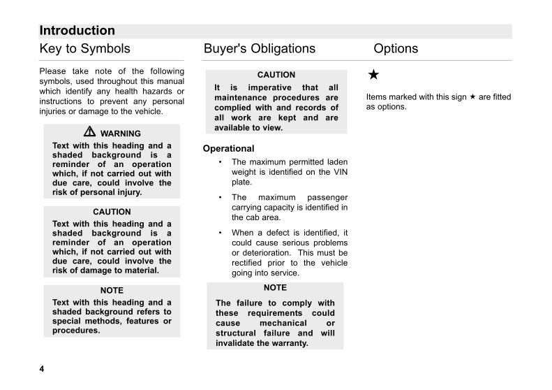
Please take note of the followingsymbols, used throughout this manualwhich identify any health hazards orinstructions to prevent any personalinjuries or damage to the vehicle.
Operational • The maximum permitted laden
weight is identified on the VINplate.
• The maximum passengercarrying capacity is identified inthe cab area.
• When a defect is identified, itcould cause serious problemsor deterioration. This must berectified prior to the vehiclegoing into service.
Items marked with this sign are fittedas options.
NOTEText with this heading and ashaded background refers tospecial methods, features orprocedures.
CAUTIONText with this heading and ashaded background is areminder of an operationwhich, if not carried out withdue care, could involve therisk of damage to material.
�� WARNINGText with this heading and ashaded background is areminder of an operationwhich, if not carried out withdue care, could involve therisk of personal injury.
Key to Symbols Buyer's Obligations Options
CAUTIONIt is imperative that allmaintenance procedures arecomplied with and records ofall work are kept and areavailable to view.
NOTE
The failure to comply withthese requirements couldcause mechanical orstructural failure and willinvalidate the warranty.
5
Table of Contents
Introduction . . . . . . . . . . . . . . . . . . 3
Key to Symbols . . . . . . . . . . . . . . . 4
General Description . . . . . . . . . . . . 7
Vehicle Identification Plate . . . . . . . 8
Vehicle Identification Sheet . . . . . . . 9
Controls and Instruments 10 - 31
Control Layout . . . . . . . . . . . .10 - 11
Instrument Panel . . . . . . . . . . 12 - 13
Warning Lights . . . . . . . . . . . .14 - 18
Switch Bank . . . . . . . . . . . . . . . . .19
Heating & Ventilation . . . . . . . . . . .20
Multi Function Switch . . . . . . 21 - 22
Automatic Gearbox Selector . 23 - 24
Reverse Interlock Button . . . . . .24
Steering Column . . . . . . . . . . . . . .25
Accelerator Pedal . . . . . . . . . . . . .26
Brake Pedal . . . . . . . . . . . . . . . . .26
Parking Brake . . . . . . . . . . . . . . . . 26
Vehicle Lift System . . . . . . . . . .27
Suspension - Kneeling System . . . 28
Doors . . . . . . . . . . . . . . . . . . . . . .29
Ramp . . . . . . . . . . . . . . . . . . . .30
Driver’s Seat . . . . . . . . . . . . . . . . .31
Emergency Equipment 32
Break Glass Hammer . . . . . . . . . .32
Fire Extinguisher . . . . . . . . . . . . . .32
Driver’s Alarm . . . . . . . . . . . . . . . .32
Emergency Exit Doors 33 - 35
Front Door . . . . . . . . . . . . . . . . . . .33
Centre Door . . . . . . . . . . . . . . . .34
Rear Door . . . . . . . . . . . . . . . . . . .35
Starting and Driving 36 - 42
CRT Exhaust - Fuel . . . . . . . . . . . 36
Engine . . . . . . . . . . . . . . . . . 36 - 37
Automatic gearbox . . . . . . . . 38 - 40
Retarder . . . . . . . . . . . . . . . . . . . . 41
Engine Shutdown . . . . . . . . . . . . . 42
Engine Emergency Stop . . . . . . . . 42
Speed Control Humps . . . . . . . . . .42
Batteries & Carrier 43
Filling Points 44 - 45
Fuel Oil . . . . . . . . . . . . . . . . . . . . .44
Windscreen Wash . . . . . . . . . . . . .44
Engine Oil - Side Dip & Fill . . . .44
Hydraulic Oil . . . . . . . . . . . . . . . . . 45
Coolant . . . . . . . . . . . . . . . . . . . . .45
6
Table of Contents
Posilock Refuelling . . . . . . . . . . . .46
Cleaning 47 - 49
Body Exterior . . . . . . . . . . . . . . . . .47
Exterior Paintwork . . . . . . . . . . .47
Body Interior . . . . . . . . . . . . . .47 - 49
ABS . . . . . . . . . . . . . . . . . . . . . .47
Moquette . . . . . . . . . . . . . . . . . .48
Panelling . . . . . . . . . . . . . . . . . .48
Fittings . . . . . . . . . . . . . . . . . . . .48
Flooring . . . . . . . . . . . . . . . .48 - 49
Maintenance 50 - 61
Maintenance Points . . . . . . . . . . . .50
Maintenance Summary . . . . . .51 - 54
Body Checks . . . . . . . . . . . . . . . . .55
Air Braking System . . . . . . . . . . . .56
Electrical System . . . . . . . . . . . . . .56
Hydraulic System . . . . . . . . . . . . .57
Cooling System . . . . . . . . . . . . . . .57
Engine Oil Level Check . . . . . . . . .57
AT 545 Gearbox Oil Level . . . . . . .58
2000 Series Gearbox Oil Level . . .58
B300R Gearbox Oil Level . . . . . . .58
Voith Gearbox Oil Level . . . . . . . . .59
Ride Height . . . . . . . . . . . . . . . . . .59
Lubrication Diagram . . . . . . . . . . .60
Lubrication Chart . . . . . . . . . . . . . .61
Emergency Repairs 62 - 66
Jacking Points . . . . . . . . . . . . 62 - 63
Tyre Pressures . . . . . . . . . . . 64 - 65
Wheels and Tyres . . . . . . . . . . . . . 66
Towing 67
Alphabetical Index 68 - 69
7
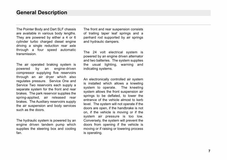
General Description
The Pointer Body and Dart SLF chassisare available in various body lengths.They are powered by either a 4 or 6cylinder turbo charged diesel enginedriving a single reduction rear axlethrough a four speed automatictransmission.
The air operated braking system ispowered by an engine-drivencompressor supplying five reservoirsthrough an air dryer which alsoregulates pressure. Service One andService Two reservoirs each supply aseparate system for the front and rearbrakes. The park reservoir supplies thespring-applied, air released rearbrakes. The Auxiliary reservoirs supplythe air suspension and body servicessuch as the doors.
The hydraulic system is powered by anengine driven tandem pump whichsupplies the steering box and coolingfan.
The front and rear suspension consistsof trailing taper leaf springs and apanhard rod supported by air springsand hydraulic dampers.
The 24 volt electrical system ispowered by an engine driven alternatorand two batteries. The system suppliesthe usual lighting, warning andindicating systems.
An electronically controlled air systemis installed which allows a kneelingsystem to operate. The kneelingsystem allows the front suspension airsprings to be deflated, to lower theentrance of the vehicle almost to kerblevel. The system will not operate if thedoors are open, if the handbrake is noton, if the vehicle is moving or if thesystem air pressure is too low.Conversely, the system will prevent thedoors from opening if the vehicle ismoving or if raising or lowering processis operating.
8
Vehicle Identification Plate
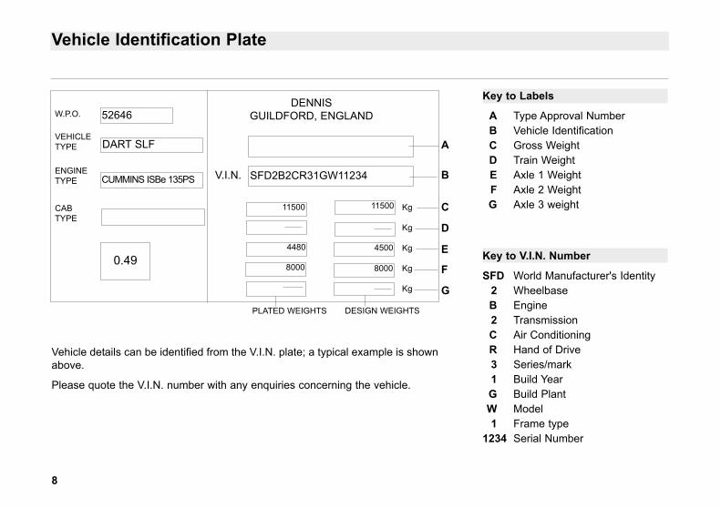
Key to Labels
A Type Approval NumberB Vehicle IdentificationC Gross WeightD Train WeightE Axle 1 WeightF Axle 2 WeightG Axle 3 weight
Key to V.I.N. Number
SFD World Manufacturer's Identity2 WheelbaseB Engine2 TransmissionC Air ConditioningR Hand of Drive3 Series/mark1 Build YearG Build PlantW Model1 Frame type
1234 Serial Number
W.P.O.
VEHICLETYPE
ENGINETYPE
CABTYPE
52646
DART SLF
CUMMINS ISBe 135PS
0.49
DENNISGUILDFORD, ENGLAND
SFD2B2CR31GW11234V.I.N.
4480
11500
8000
4500
8000
Kg
Kg
Kg
Kg
Kg
A
B
C
D
E
F
G
PLATED WEIGHTS DESIGN WEIGHTS
11500
Vehicle details can be identified from the V.I.N. plate; a typical example is shownabove.
Please quote the V.I.N. number with any enquiries concerning the vehicle.
9
Vehicle Identification Sheet
Chassis
V.I.N. No . . . . . . . . . . . . . . . . . . . . . . . . . . . . . . . . . . . . . . .
Model . . . . . . . . . . . . . . . . . . . . . . . . . . . . . . . . . . . . . . . . .
Registration No . . . . . . . . . . . . . . . . . . . . . . . . . . . . . . . . . .
Date into service . . . . . . . . . . . . . . . . . . . . . . . . . . . . . . . . .
Engine Type . . . . . . . . . . . . . . . . . . . . . . . . . . . . . . . . . . . .
Engine Number . . . . . . . . . . . . . . . . . . . . . . . . . . . . . . . . . .
Gearbox Type . . . . . . . . . . . . . . . . . . . . . . . . . . . . . . . . . . .
Gearbox Number . . . . . . . . . . . . . . . . . . . . . . . . . . . . . . . . .
Wheel Tyre Size . . . . . . . . . . . . . . . . . . . . . . . . . . . . . . . . .
Bodywork
Bodybuilder . . . . . . . . . . . . . . . . . . . . . . . . . . . . . . . . . . . . .
Body Type . . . . . . . . . . . . . . . . . . . . . . . . . . . . . . . . . . . . . .
Body Number . . . . . . . . . . . . . . . . . . . . . . . . . . . . . . . . . . .
Operator
Company . . . . . . . . . . . . . . . . . . . . . . . . . . . . . . . . . . . . . . .
Address . . . . . . . . . . . . . . . . . . . . . . . . . . . . . . . . . . . . . . . .
Telephone Number . . . . . . . . . . . . . . . . . . . . . . . . . . . . . . .
Out of Hours Telephone Number . . . . . . . . . . . . . . . . . . . . .
Fax Number . . . . . . . . . . . . . . . . . . . . . . . . . . . . . . . . . . . . .
10
Control Layout
WAIT TOSTART
BAR BAR
2
1508555 km/h
Drive can only beselected when thefootbrake is depressed
CAUTION
OFF H
AN
DB
RA
KE
ON
WHEELCHAIR RAMPMaximum safe
working load - 300kg
OPEN�DOOR
CLOSEDOOR
OPEN�DOOR
CLOSEDOOR
LOWER RAISE
FRONT SUSPENSION
EXTEND RETRACT
WHEELCHAIR RAMP
2 4
6
1
7
5
8
RND321
MORSECONTROLS
9 10 11 12 13
3
11
Control Layout
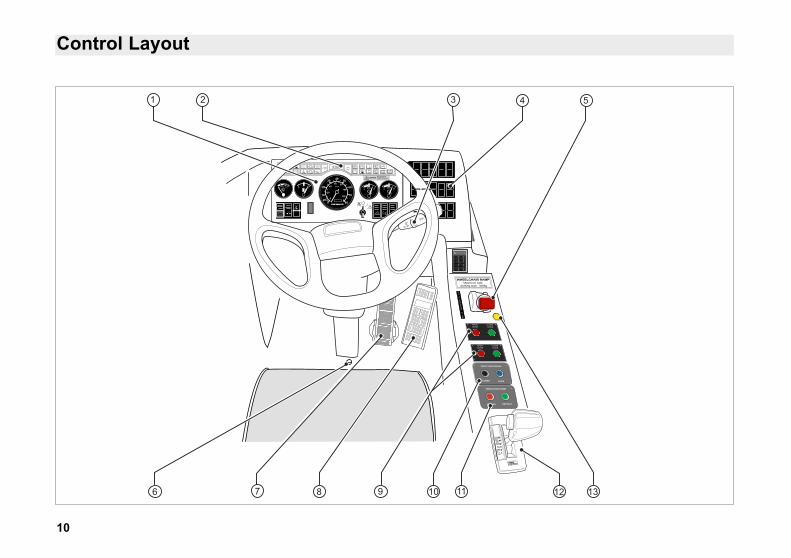
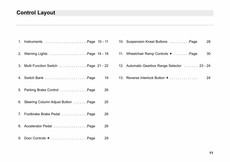
1. Instruments . . . . . . . . . . . . . . . . . . . . .Page 10 - 11
2. Warning Lights . . . . . . . . . . . . . . . . . . .Page 14 - 18
3. Multi Function Switch . . . . . . . . . . . . . .Page 21 - 22
4. Switch Bank . . . . . . . . . . . . . . . . . . . . .Page 19
5. Parking Brake Control . . . . . . . . . . . . . .Page 26
6. Steering Column Adjust Button . . . . . . .Page 25
7. Footbrake Brake Pedal . . . . . . . . . . . . .Page 26
8. Accelerator Pedal . . . . . . . . . . . . . . . . .Page 26
9. Door Controls . . . . . . . . . . . . . . . . . .Page 29
10. Suspension Kneel Buttons . . . . . . . . . .Page 28
11. Wheelchair Ramp Controls . . . . . . . .Page 30
12. Automatic Gearbox Range Selector . . . . . . . 23 - 24
13. Reverse Interlock Button . . . . . . . . . . . . . . 24
12
Instrument Panel
BAR BAR
2
km/hF
260120
Drive can only beselected when thefootbrake is depressed
CAUTION
2 4
87
6531
10 11 12
WAIT TOSTART
9 13
13
Instrument Panel
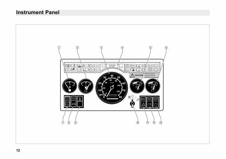
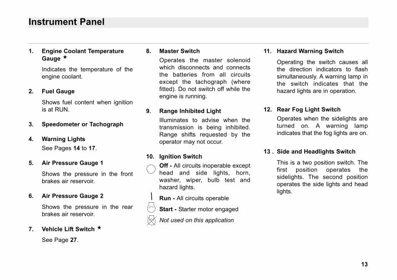
1. Engine Coolant TemperatureGauge
Indicates the temperature of theengine coolant.
2. Fuel Gauge
Shows fuel content when ignitionis at RUN.
3. Speedometer or Tachograph
4. Warning LightsSee Pages 14 to 17.
5. Air Pressure Gauge 1
Shows the pressure in the frontbrakes air reservoir.
6. Air Pressure Gauge 2
Shows the pressure in the rearbrakes air reservoir.
7. Vehicle Lift Switch
See Page 27.
8. Master SwitchOperates the master solenoidwhich disconnects and connectsthe batteries from all circuitsexcept the tachograph (wherefitted). Do not switch off while theengine is running.
9. Range Inhibited LightIlluminates to advise when thetransmission is being inhibited.Range shifts requested by theoperator may not occur.
10. Ignition SwitchOff - All circuits inoperable excepthead and side lights, horn,washer, wiper, bulb test andhazard lights.
Run - All circuits operable
Start - Starter motor engaged
Not used on this application
11. Hazard Warning Switch
Operating the switch causes allthe direction indicators to flashsimultaneously. A warning lamp inthe switch indicates that thehazard lights are in operation.
12. Rear Fog Light SwitchOperates when the sidelights areturned on. A warning lampindicates that the fog lights are on.
13 . Side and Headlights Switch
This is a two position switch. Thefirst position operates thesidelights. The second positionoperates the side lights and headlights.
Warning Lights
WAIT TOSTART
14
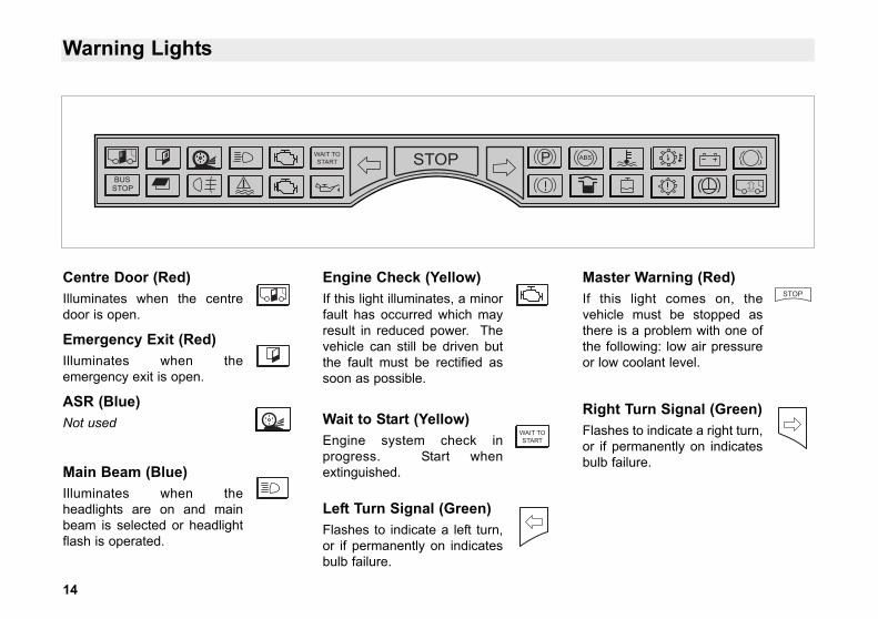
Centre Door (Red)Illuminates when the centredoor is open.
Emergency Exit (Red)Illuminates when theemergency exit is open.
ASR (Blue)Not used
Main Beam (Blue)Illuminates when theheadlights are on and mainbeam is selected or headlightflash is operated.
Engine Check (Yellow)If this light illuminates, a minorfault has occurred which mayresult in reduced power. Thevehicle can still be driven butthe fault must be rectified assoon as possible.
Wait to Start (Yellow)Engine system check inprogress. Start whenextinguished.
Left Turn Signal (Green)Flashes to indicate a left turn,or if permanently on indicatesbulb failure.
Master Warning (Red)If this light comes on, thevehicle must be stopped asthere is a problem with one ofthe following: low air pressureor low coolant level.
Right Turn Signal (Green)Flashes to indicate a right turn,or if permanently on indicatesbulb failure.
WAIT TOSTART
15
Warning Lights
WAIT TOSTART
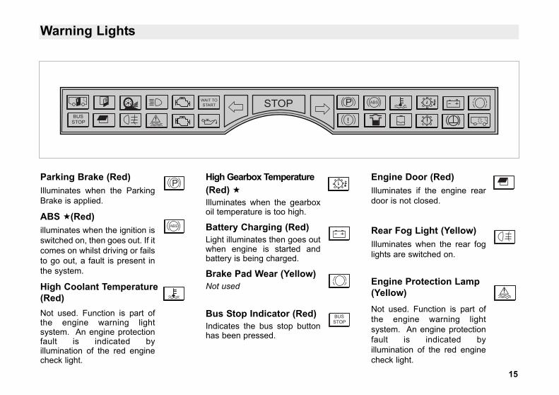
Parking Brake (Red)Illuminates when the ParkingBrake is applied.
ABS (Red)illuminates when the ignition isswitched on, then goes out. If itcomes on whilst driving or failsto go out, a fault is present inthe system.
High Coolant Temperature(Red)Not used. Function is part ofthe engine warning lightsystem. An engine protectionfault is indicated byillumination of the red enginecheck light.
High Gearbox Temperature(Red) Illuminates when the gearboxoil temperature is too high.
Battery Charging (Red)Light illuminates then goes outwhen engine is started andbattery is being charged.
Brake Pad Wear (Yellow)Not used
Bus Stop Indicator (Red)Indicates the bus stop buttonhas been pressed.
Engine Door (Red)Illuminates if the engine reardoor is not closed.
Rear Fog Light (Yellow)Illuminates when the rear foglights are switched on.
Engine Protection Lamp(Yellow)Not used. Function is part ofthe engine warning lightsystem. An engine protectionfault is indicated byillumination of the red enginecheck light.
16
Warning Lights
WAIT TOSTART
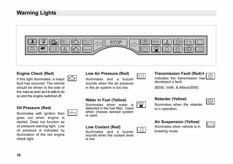
Engine Check (Red)If this light illuminates, a majorfault has occurred. The vehicleshould be driven to the side ofthe road as soon as it is safe to doso and the engine switched off.
Oil Pressure (Red)Illuminates with ignition thengoes out when engine isstarted. Does not function asoil pressure warning light. Lowoil pressure is indicated byillumination of the red enginecheck light.
Low Air Pressure (Red)illuminates and a buzzersounds when the air pressurein the air system is too low.
Water in Fuel (Yellow)Illuminates when water isdetected in the fuel filter. Usedwhen chassis sensed systemis used.
Low Coolant (Red)Illuminates and a buzzersounds when the coolant levelis low.
Transmission Fault (Red)Indicates the transmission hasdeveloped a fault.(B300, Voith, & Allison2000)
Retarder (Yellow)Illuminates when the retarderis in operation.
Air Suspension (Yellow)Illuminates when vehicle is inkneeling mode.
17
Warning Lights
Warning Light FunctionThe warning lamp informs the driver ofthe system condition and to transmitblink codes for system and diagnosticinformation.
If the warning lamp fails to go out whenthe vehicle is driven off, or if it comeson shortly after drive off, this is anindication that the ABS system is eitherdisabled or partially disabled due to afault. If the system is disabled the driverstill has full use of the conventionalbraking system. When the warninglamp lights up this indicates increaseddanger of wheel lock-up. The drivershould exercise caution when brakingto avoid loss of control due to wheelskid.
The warning lamp is switched on (bulbcheck) after “ignition on”. If a wheelspeed sensor fault was not stored inthe fault memory before the last“ignition off”, the warning lamp will beswitched off about 2 seconds after“ignition on”, provided the static systemtest was successfully completed. The
warning lamp the remains switched offwhen the dynamic system test hassuccessfully concluded
If a wheel speed sensor fault wasstored before the last “ignition off”, thewarning lamp remains on until thestatic and dynamic system test hassuccessfully been completed - a storedfault.
• The driver is responsible fortaking note of the warninglamp. If the warning lamp failsto light up immediately after“ignition on” this indicates thatthe lamp bulb is defective. ItMUST be replaced withoutdelay.
• When a fault occurs, it isessential that the ABS ischecked immediately in anauthorised workshop in order torepair the fault and return thesystem to normal operation.Failure to do so may result inunforeseen consequences.
Safety InstructionWhile the ABS increases the vehiclesafety, it is not able to overcome naturalphysical laws. ABS can only optimisethe utilisation of the available tractionbetween the tyres and the road. ABS isnot able to compensate for poordriving, to avoid the consequences ofdriving too close to the vehicle in front,and/or driving into a bend withexcessive speed.
ABS
18
Warning Lights
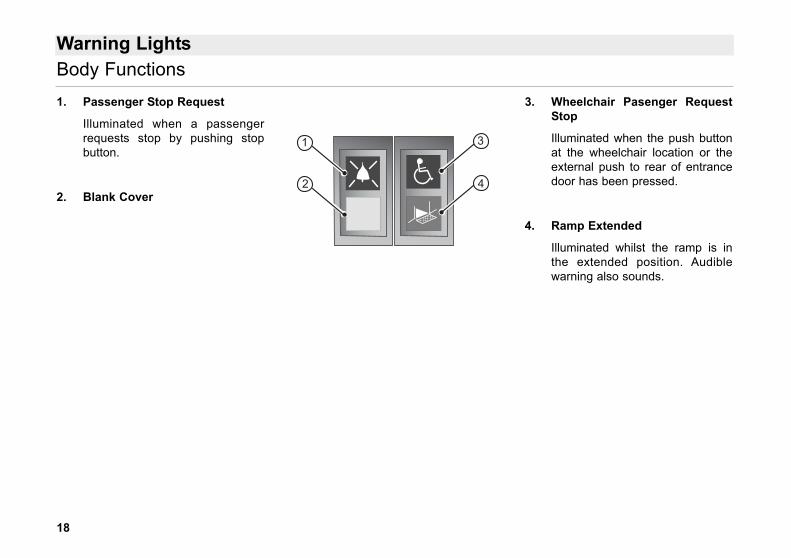
1. Passenger Stop Request
Illuminated when a passengerrequests stop by pushing stopbutton.
2. Blank Cover
3. Wheelchair Pasenger RequestStop
Illuminated when the push buttonat the wheelchair location or theexternal push to rear of entrancedoor has been pressed.
4. Ramp Extended
Illuminated whilst the ramp is inthe extended position. Audiblewarning also sounds.
Body Functions
31
2 4
19
Controls
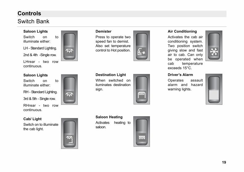
Saloon LightsSwitch on toilluminate either:
LH - Standard Lighting.
2nd & 4th -Single row.
LHrear - two rowcontinuous.
Saloon LightsSwitch on toilluminate either:
RH - Standard Lighting.
3rd & 5th - Single row.
RHrear - two rowcontinuous.
Cab/ LightSwitch on to illuminatethe cab light.
DemisterPress to operate twospeed fan to demist.Also set temperaturecontrol to Hot position.
Destination LightWhen switched oniluminates destinationsign.
Saloon HeatingActivates heating tosaloon.
Air ConditioningActivates the cab airconditioning system.Two position switchgiving slow and fastair to cab. Can onlybe operated whencab temperatureexceeds 15°C.
Driver’s AlarmOperates assaultalarm and hazardwarning lights.
Switch Bank
20
Controls
General
The system consists of two parts:
1. Saloon - heating provided byconvectors running along bothsides of the vehicle.
2. Cab and entrance area -demisting, heating and ventilationprovided by radiator/fan unitlocated below the LH front dash.
Permanently open outlets arepositioned across the front of thedash for efficient windscreendemisting.
A permanently open outlet ispositioned at floor level, in theentrance area for heating andventilation.
Adjustable rotary vents arepositioned in the driver’s cab.These provide heat or ventilationto the cab or heat or ventilation tothe driver’s footwell . . . . . area.
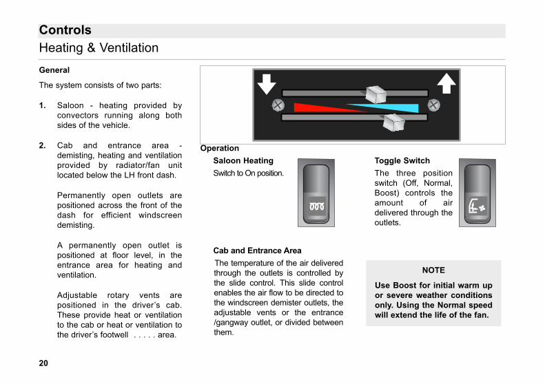
OperationSaloon HeatingSwitch to On position.
Cab and Entrance AreaThe temperature of the air deliveredthrough the outlets is controlled bythe slide control. This slide controlenables the air flow to be directed tothe windscreen demister outlets, theadjustable vents or the entrance/gangway outlet, or divided betweenthem.
Toggle SwitchThe three positionswitch (Off, Normal,Boost) controls theamount of airdelivered through theoutlets.
Heating & Ventilation
NOTE
Use Boost for initial warm upor severe weather conditionsonly. Using the Normal speedwill extend the life of the fan.
21
Controls
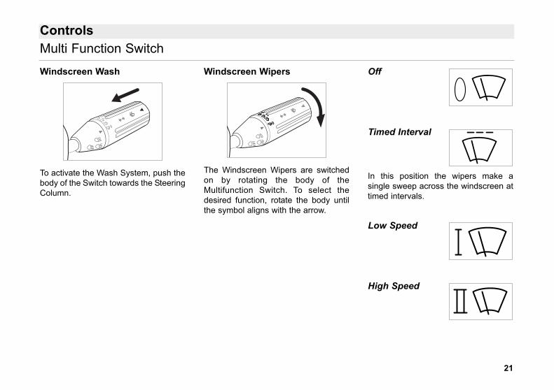
Windscreen Wash
To activate the Wash System, push thebody of the Switch towards the SteeringColumn.
Windscreen Wipers
The Windscreen Wipers are switchedon by rotating the body of theMultifunction Switch. To select thedesired function, rotate the body untilthe symbol aligns with the arrow.
Off
Timed Interval
In this position the wipers make asingle sweep across the windscreen attimed intervals.
Low Speed
High Speed
Multi Function Switch
Controls
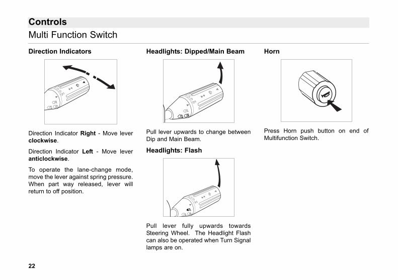
Direction Indicators
Direction Indicator Right - Move leverclockwise.
Direction Indicator Left - Move leveranticlockwise.
To operate the lane-change mode,move the lever against spring pressure.When part way released, lever willreturn to off position.
Headlights: Dipped/Main Beam
Pull lever upwards to change betweenDip and Main Beam.
Headlights: Flash
Pull lever fully upwards towardsSteering Wheel. The Headlight Flashcan also be operated when Turn Signallamps are on.
Horn
Press Horn push button on end ofMultifunction Switch.
Multi Function Switch
22
23
Controls
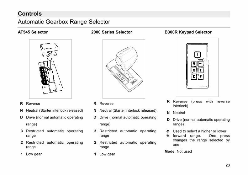
AT545 Selector
R Reverse
N Neutral (Starter interlock released)
D Drive (normal automatic operating
range)
3 Restricted automatic operatingrange
2 Restricted automatic operatingrange
1 Low gear
2000 Series Selector
R Reverse
N Neutral (Starter interlock released)
D Drive (normal automatic operating
range)
3 Restricted automatic operatingrange
2 Restricted automatic operatingrange
1 Low gear
B300R Keypad Selector
R Reverse (press with reverseinterlock)
N Neutral
D Drive (normal automatic operatingrange)
Used to select a higher or lowerforward range. One presschanges the range selected byone
Mode Not used
RND321
MORSE
CONTROLS
Automatic Gearbox Range Selector
24
Controls
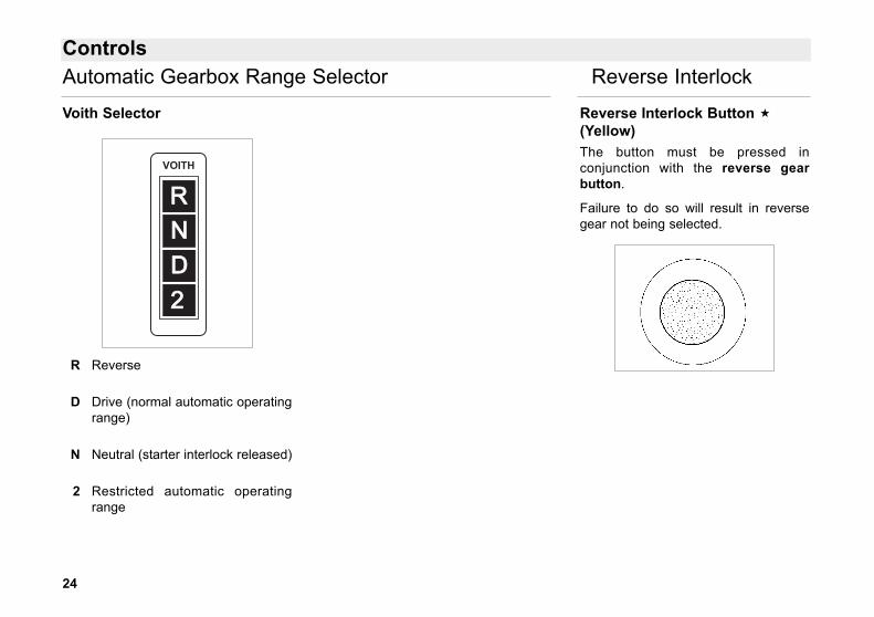
Voith Selector
R Reverse
D Drive (normal automatic operatingrange)
N Neutral (starter interlock released)
2 Restricted automatic operatingrange
Reverse Interlock Button (Yellow)The button must be pressed inconjunction with the reverse gearbutton.
Failure to do so will result in reversegear not being selected.
RVOITH
2DN
Automatic Gearbox Range Selector Reverse Interlock
25
Controls
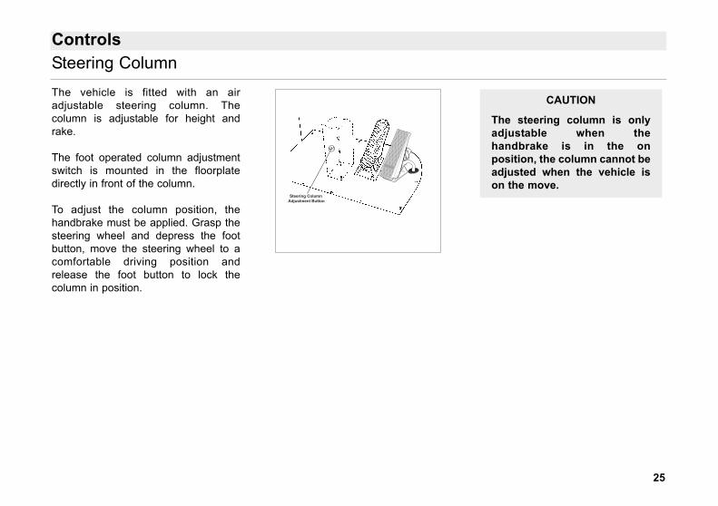
The vehicle is fitted with an airadjustable steering column. Thecolumn is adjustable for height andrake.
The foot operated column adjustmentswitch is mounted in the floorplatedirectly in front of the column.
To adjust the column position, thehandbrake must be applied. Grasp thesteering wheel and depress the footbutton, move the steering wheel to acomfortable driving position andrelease the foot button to lock thecolumn in position.
CAUTION
The steering column is onlyadjustable when thehandbrake is in the onposition, the column cannot beadjusted when the vehicle ison the move.
Steering Column Adjustment Button
Steering Column
26
Controls
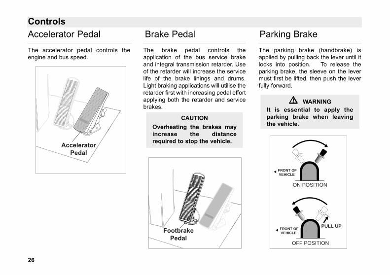
The accelerator pedal controls theengine and bus speed.
The brake pedal controls theapplication of the bus service brakeand integral transmission retarder. Useof the retarder will increase the servicelife of the brake linings and drums.Light braking applications will utilise theretarder first with increasing pedal effortapplying both the retarder and servicebrakes.
The parking brake (handbrake) isapplied by pulling back the lever until itlocks into position. To release theparking brake, the sleeve on the levermust first be lifted, then push the leverfully forward.
�� WARNINGIt is essential to apply theparking brake when leavingthe vehicle.
CAUTIONOverheating the brakes mayincrease the distancerequired to stop the vehicle.
SB1289 Euro 3 Dart Foot Pedals
AcceleratorPedal
Accelerator Pedal Brake Pedal Parking Brake
SB1289 Euro 3 Dart Foot Pedals
FootbrakePedal
FRONT OFVEHICLE
ON POSITION
OFF POSITION
PULL UP
FRONT OFVEHICLE
27
Controls
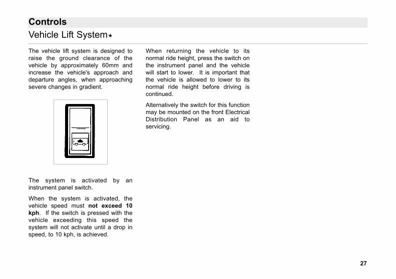
The vehicle lift system is designed toraise the ground clearance of thevehicle by approximately 60mm andincrease the vehicle's approach anddeparture angles, when approachingsevere changes in gradient.
The system is activated by aninstrument panel switch.
When the system is activated, thevehicle speed must not exceed 10kph. If the switch is pressed with thevehicle exceeding this speed thesystem will not activate until a drop inspeed, to 10 kph, is achieved.
When returning the vehicle to itsnormal ride height, press the switch onthe instrument panel and the vehiclewill start to lower. It is important thatthe vehicle is allowed to lower to itsnormal ride height before driving iscontinued.
Alternatively the switch for this functionmay be mounted on the front ElectricalDistribution Panel as an aid toservicing.
Vehicle Lift System
28
Controls
The Kneeling System may be fitted withoptions specified by the Bodybuilderbut not covered on this page.Operators must familiarise themselveswith any instructions issued by theBodybuilder.
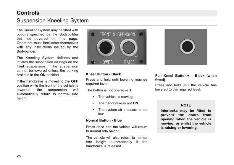
The Kneeling System deflates andinflates the suspension air bags on thefront suspension. The suspensioncannot be lowered unless the parkingbrake is in the ON position.
If the handbrake is moved to the OFFposition while the front of the vehicle islowered, the suspension willautomatically return to normal rideheight.
Kneel Button - BlackPress and hold until lowering reachesrequired level.
The button is not operative if:
• The vehicle is moving.
• The handbrake is not ON.
• The system air pressure is toolow.
Normal Button - Blue
Press once and the vehicle will returnto normal ride height.
The vehicle will also return to normalride height automatically if thehandbrake is released.
Full Kneel Button - Black (whenfitted)Press and hold until the vehicle haslowered to the required level.
NOTEInterlocks may be fitted toprevent the doors fromopening when the vehicle ismoving, or whilst the vehicleis raising or lowering.
Suspension Kneeling System
29
Steering Column Adjustment Button
Controls
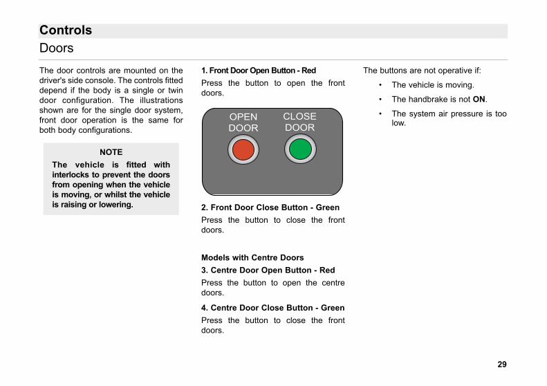
The door controls are mounted on thedriver's side console. The controls fitteddepend if the body is a single or twindoor configuration. The illustrationsshown are for the single door system,front door operation is the same forboth body configurations.
1. Front Door Open Button - RedPress the button to open the frontdoors.
2. Front Door Close Button - GreenPress the button to close the frontdoors.
Models with Centre Doors3. Centre Door Open Button - RedPress the button to open the centredoors.
4. Centre Door Close Button - GreenPress the button to close the frontdoors.
The buttons are not operative if:
• The vehicle is moving.
• The handbrake is not ON.
• The system air pressure is toolow.
NOTEThe vehicle is fitted withinterlocks to prevent the doorsfrom opening when the vehicleis moving, or whilst the vehicleis raising or lowering.
Doors
OPENDOOR
CLOSEDOOR
30
Steering Column Adjustment Button
Controls
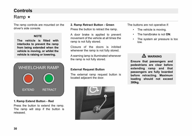
The ramp controls are mounted on thedriver's side console.
1. Ramp Extend Button - RedPress the button to extend the ramp.The ramp will stop if the button isreleased.
2. Ramp Retract Button - GreenPress the button to retract the ramp.
A door brake is applied to preventmovement of the vehicle at all times theramp is not fully stored.
Closure of the doors is inibitedwhenever the ramp is not fully stored.
A warning lamp is illuminated wheneverthe ramp is not fully stored.
External Request Button
The external ramp request button islocated adjacent the door.
The buttons are not operative if: • The vehicle is moving. • The handbrake is not ON. • The system air pressure is too
low.
NOTEThe vehicle is fitted withinterlocks to prevent the rampfrom being extended when thevehicle is moving, or whilst thevehicle is raising or lowering.
Ramp
EXTEND
WHEELCHAIR RAMP
RETRACT
�� WARNINGEnsure that passengers andpedestrians are clear beforeextending ramp and thatpassengers are fully boardedbefore retracting. Maximumloading should not exceed300kg.
1A
31
Controls
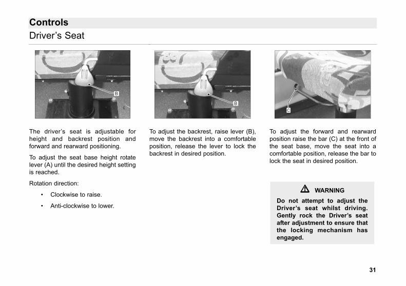
The driver’s seat is adjustable forheight and backrest position andforward and rearward positioning.
To adjust the seat base height rotatelever (A) until the desired height settingis reached.
Rotation direction:
• Clockwise to raise.
• Anti-clockwise to lower.
To adjust the backrest, raise lever (B),move the backrest into a comfortableposition, release the lever to lock thebackrest in desired position.
To adjust the forward and rearwardposition raise the bar (C) at the front ofthe seat base, move the seat into acomfortable position, release the bar tolock the seat in desired position.
�� WARNINGDo not attempt to adjust theDriver’s seat whilst driving.Gently rock the Driver’s seatafter adjustment to ensure thatthe locking mechanism hasengaged.
C
B
B
Driver’s Seat
32
Emergency Equipment
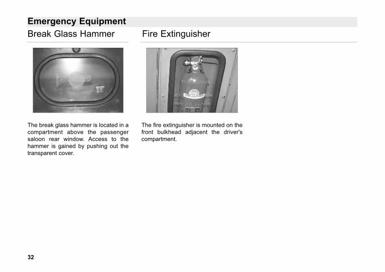
The break glass hammer is located in acompartment above the passengersaloon rear window. Access to thehammer is gained by pushing out thetransparent cover.
The fire extinguisher is mounted on thefront bulkhead adjacent the driver'scompartment.
Break Glass Hammer Fire Extinguisher
33
Emergency Exit Doors
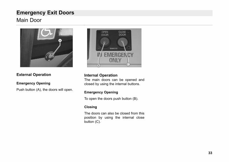
External Operation
Emergency Opening
Push button (A), the doors will open.
Internal OperationThe main doors can be opened andclosed by using the internal buttons.
Emergency Opening
To open the doors push button (B).
Closing
The doors can also be closed from thisposition by using the internal closebutton (C).
B C
1A
Main Door
34
Emergency Exit Doors
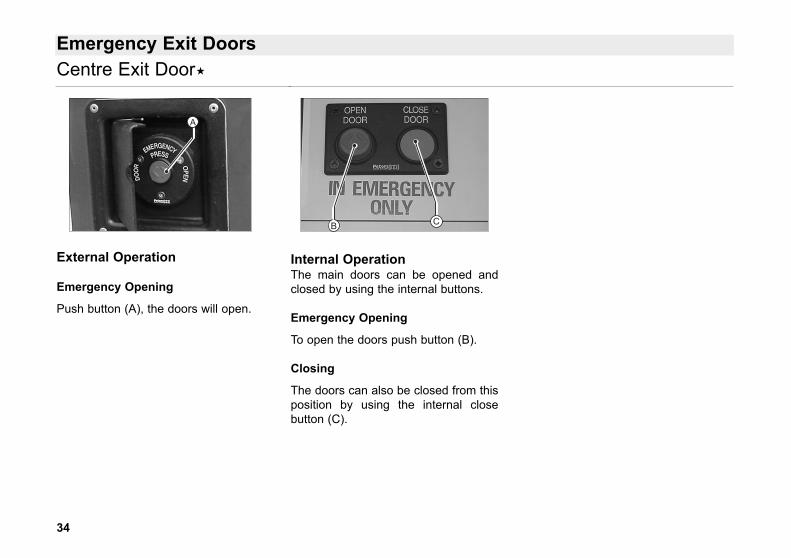
External Operation
Emergency Opening
Push button (A), the doors will open.
Internal OperationThe main doors can be opened andclosed by using the internal buttons.
Emergency Opening
To open the doors push button (B).
Closing
The doors can also be closed from thisposition by using the internal closebutton (C).
B C
1A
Centre Exit Door
35
Emergency Exit Doors
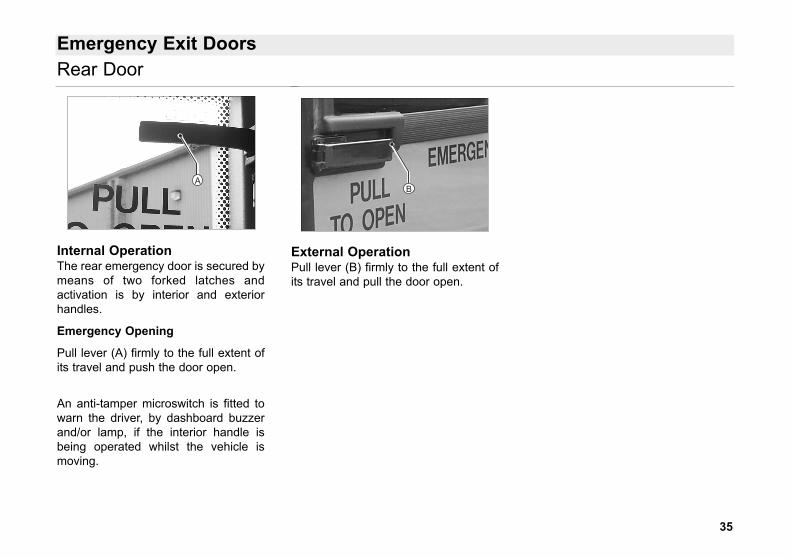
Internal OperationThe rear emergency door is secured bymeans of two forked latches andactivation is by interior and exteriorhandles.
Emergency Opening
Pull lever (A) firmly to the full extent ofits travel and push the door open.
An anti-tamper microswitch is fitted towarn the driver, by dashboard buzzerand/or lamp, if the interior handle isbeing operated whilst the vehicle ismoving.
External OperationPull lever (B) firmly to the full extent ofits travel and pull the door open.
B
Rear Door
A
36
Starting and DrivingCRT Exhaust Engine
Fuel RequirementVehicles fitted with a CRT exhaustsystem (Continuously RegeneratingTrap) MUST be run on low sulphurdiesel fuel (such as City diesel) with amaximum sulphur content of 0.5%.
Normal Starting Procedure
• Ensure the parking brake is inthe ON position.
• Select neutral gear. • Turn master switch on. • Turn ignition switch to RUN and
wait for WAIT-TO-START lightto go out.
• This lamp is also illuminatedwhile the inlet manifold isheating (grid heater).
• Turn ignition switch to START.As soon as the engine hasstarted, release the switch toRun.
• Check that the battery chargewarning light goes out.
• Idle the engine for 3 - 5 minutesbefore operating with a load
CAUTION
Do not operate the starter formore than 30 Secondscontinuously. Wait 2 minutesbetween each attempt to start.If the engine oil pressurewarning light does not go outwithin 15 seconds of starting.Stop the engine.
CAUTION
Do not operate the engine athigh rpm when starting theengine in temperatures below+3°C as damage may be causedto the hydraulic pump.
CAUTIONIt is imperative that this startingprocedure is followed correctlyto allow the Cummins ECM(engine control module) to runthrough its initialisationsequence.Failure to apply this startingprocedure could result in theengine warning system beingactivated.
37
Starting and Driving
Shutting Down
After full load operation, idle the enginefor 3 - 5 minutes before shutting off toallow the oil and coolant to remove heatfrom many parts, especially theturbocharger.
To stop the engine, turn the ignitionswitch to OFF.
Engine Operation
• Do not operate the engine atfull throttle below peak torquerpm for more than 30 seconds
• Allow the engine to idle 3 to 5minutes before shutting it off.
• Shut the engine off if the oilpressure warning light orcoolant temperature warninglight comes on.
Most failures give an early warning.
Look and listen for changes inperformance, sound, engineappearance that can indicate service orengine repair is needed.
Some changes to look for are
• Engine misfire
• Excessive smoke
• Vibration
• Loss of power
• Unusual engine noise
• An increase in engine noise
• Fuel, oil or coolant leaks
• An increase in fuelconsumption
• Sudden changes in engineoperating temperature or oilpressure.
Check List Before Moving Off
• Check that the air pressurereading on both gauges is notin the red sector.
• Check that the engine is idlingsatisfactorily.
• See that no warning lights areshowing except the handbrake.
CAUTIONContinuous operation withlow coolant temperaturebelow 60°C or high coolanttemperature above 100°Ccan damage the engine.
Engine
38
Starting and Driving
Starting and Driving Away
The engine can only be started with theneutral button (N) selected. With thevehicle standing still, the parking brakeapplied, and the engine running atidling speed, preselect the desiredspeed range, wait 1 to 2 seconds, thenrelease the brakes and drive away bydepressing the accelerator.
If a speed range is selected with theengine speed above 900rpm and/orwith the accelerator depressed, aninterlock in the automatic control unitprevents a gear being selected.
Only when the engine speed is below900rpm and the accelerator is in theidling position is the gear selected.
CAUTIONNever accelerate whenoperating the speed rangeselector.
CAUTIONAt temperatures below -23°C,start the engine and warm upthe gearbox in neutral forapprox 10 to 15 minutesbefore selecting speed range.
NOTETo assist drivers in correctlylocating the pedals beforeengaging gear the vehicle isfitted with a change speedinterlock. With this interlock fitted, drivecan only be selected when thefootbrake is depressed.
�� WARNINGAn accident may occur, ifinadvertently the acceleratorpedal is depressed instead ofthe footbrake whilst thegearbox is in gear. Typicallysuch incidents can arise whenmoving off before properlylocating the pedals. Thedriver wishing to check thevehicle's initial movementunintentionally presses theaccelerator instead of thefootbrake.
Automatic Gearbox
39
Starting and Driving
Speed Ranges
The transmission will prevent a changeinto any range at a speed which willcause the engine to over speed.
Any lower range may be selected atany time, but will only engage when theroad speed is reduced.
The inhibit effect will cause changingdown to occur at a slightly higherspeeds than normal.
R ReverseThe vehicle must be completelystationary before changing fromforward to reverse or reverse toforward. This selection has thegreatest tractive advantage.
N NeutralUse this position when starting theengine. If the engine will start in anyother position, the auto cut-out is notworking. Neutral should also beselected when experiencing longerthan normal periods of idling. Alwaysapply the handbrake.
D DriveThis is the normal forward gear. Whenthe accelerator is depressed, thevehicle will move off in first gear andchange up progressively to top gear asthe speed builds up. As the vehicleslows down, the transmission willchange down into the correct gear forrestarting
2 or 3If the road or traffic conditions make itdesirable to prevent the transmissionchanging into a higher gear, either 2 or3 should be selected to limit the range.These positions provide progressivelygreater engine braking power, the 2range having the greatest effect.When conditions improve, return theselector to the normal driving position.
1This is the low gear for use whenpulling through mud and snow ordrawing up steep grades. This positionalso provides maximum engine brakingpower.
CAUTIONNever change from neutral (N)to drive (D) or reverse (R) atengine speeds above idle.The vehicle will lurchforwards or backward and thetransmission will bedamaged.
CAUTIONDo not allow the vehicle tocoast in neutral. This practicecan result in severetransmission damage. Alsono engine braking isavailable.
Automatic Gearbox
40
Starting and Driving
On certain gradients the gearbox maytend to “hunt”, that is to shift up anddown at frequent intervals. This isbecause the available power is just toolow for the higher ratio and yet too highfor the lower ratio. In such cases, easeback the accelerator or select a lowerratio manually.
In the same way, use the selector toobtain a lower ratio when descending asteep gradient, so that the gearboxdoes not shift up too far and reduce theengine braking effect.
The next lower ratio can be selectedrapidly when needed (for instancewhen accelerating or tackling a suddengradient) by depressing the acceleratorto the kickdown position. This pedalposition effects the earliest possibledown-shift into the lower gear.
Stopping in TrafficDuring short stops at traffic lights etcthe gearbox need not be returned toneutral, but the vehicle brake should beapplied to prevent the vehicle fromcreeping forwards.
During longer stops the neutral (N)button should be selected and thehandbrake applied.
Stopping the EngineThe vehicle can be stopped at anytime, regardless of the selectorposition.
As the vehicle comes to a halt theautomatic control will shift down to thecorresponding ratio for restartingdepending on the drive range.
Driving DownhillSelect a suitable gear ratio beforereaching the downhill gradient andreduce speed so that the gearbox shiftsdown to the highest ratio of the rangeselected. This will prevent the gearboxfrom shifting back to a higher speedrange automatically.
Driving on Ice or SnowThe automatic gearbox continuallyprovides proper balance betweenrequired power and good traction. Thedriver can have better control of hisvehicle because of this smooth,
constant flow of power through thedrive train. When driving on ice orsnow, any acceleration or decelerationshould be made gradually.
Parking
CAUTIONSince the clutches andbrakes in the gearbox aredisengaged when the engineis stopped, there is no directmechanical link between theengine and driven roadwheels. Therefore it isessential to apply the parkingbrake when leaving thevehicle. In addition, it is goodpractice on slopes to chockthe wheels, thus ensuringthat the vehicle cannot rollaway.
Automatic Gearbox

41
Starting and Driving
The retarder is an electromagneticbrake, and suffers no mechanical wear.This saves wear on the service brakesand in an emergency the full brakingeffect (no fading) of the service brakesis available.
Therefore application of the retarder isrecommended on lengthy gradients orwhen slowing down from high speed.
A slight pressure on the brake pedalbrings the retarder progressively intooperation, carrying it through thestages of operation.
No special equipment is visible in thedriver's cab, except a retarder warninglamp which illuminates when theretarder is in operation.
Retarder
42
Starting and Driving
• Apply the handbrake.
• Allow the engine to idle for afew moments to allow evencooling.
• Turn the ignition switch to OFFO.
• Turn off the master switch. Thismust not be done before theengine has stopped.
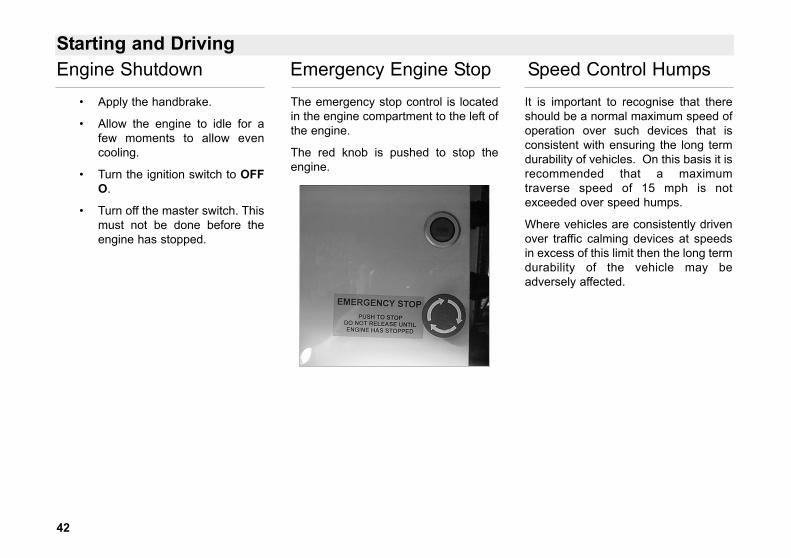
The emergency stop control is locatedin the engine compartment to the left ofthe engine.
The red knob is pushed to stop theengine.
It is important to recognise that thereshould be a normal maximum speed ofoperation over such devices that isconsistent with ensuring the long termdurability of vehicles. On this basis it isrecommended that a maximumtraverse speed of 15 mph is notexceeded over speed humps.
Where vehicles are consistently drivenover traffic calming devices at speedsin excess of this limit then the long termdurability of the vehicle may beadversely affected.
Engine Shutdown Emergency Engine Stop Speed Control Humps
43
Batteries & Carrier
Battery Jump Starting
GeneralDirect connection of either slavebatteries or a donor vehicle battery to aflat battery may result in an explosion.
Adhere to the following procedureswhen jump starting batteries:
Method 1Use the boost socket only to connectdonor battery to the recipient battery.
Method 2As an alternative to method 1, thepositive connection may still be madedirectly, but the negative terminalMUST NOT be connected directly tothe recipient battery terminal. Thisshould be connected to a remotechassis earth point. If a boost socket isnot fitted to the vehicle then the positiveconnection may be made directly, butthe negative terminal MUST NOT beconnected directly to the recipientbattery terminal. This should beconnected to a remote chassis earthpoint.
This position should be far enoughaway from the battery to ensure thatany spark generated by disconnectionwill not reach the gas produced at thebattery.
When disconnecting the battery, theremote negative connection MUST beremoved first.
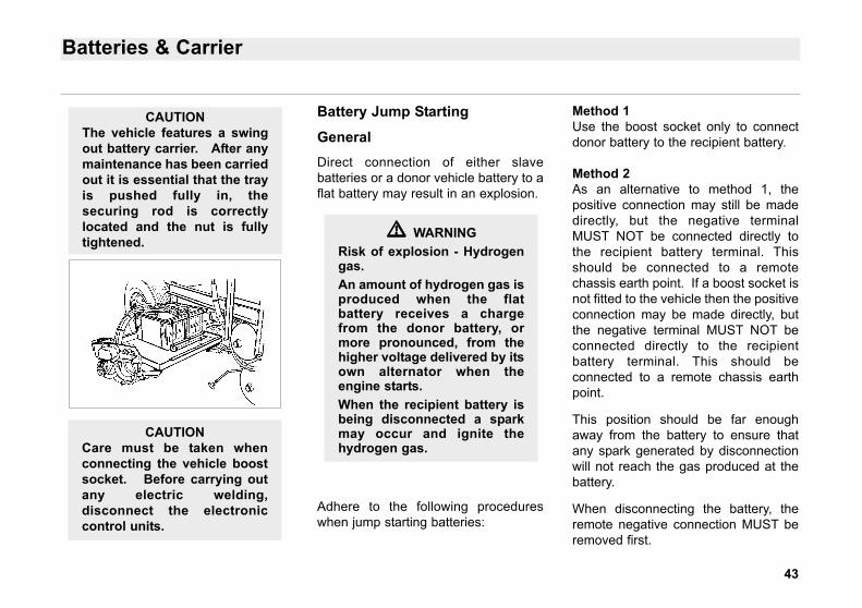
CAUTIONThe vehicle features a swingout battery carrier. After anymaintenance has been carriedout it is essential that the trayis pushed fully in, thesecuring rod is correctlylocated and the nut is fullytightened.
CAUTIONCare must be taken whenconnecting the vehicle boostsocket. Before carrying outany electric welding,disconnect the electroniccontrol units.
�� WARNINGRisk of explosion - Hydrogengas.An amount of hydrogen gas isproduced when the flatbattery receives a chargefrom the donor battery, ormore pronounced, from thehigher voltage delivered by itsown alternator when theengine starts.When the recipient battery isbeing disconnected a sparkmay occur and ignite thehydrogen gas.

44
Filling Points
The filler cap is located behind theaccess door flap located at the rearoffside off the vehicle. Ensure that thefiller cap is correctly fitted after re-fuelling.
The windscreen washer reservoir islocated behind the body front outeraccess panel below the windscreen.The panel is secured by lock catcheson each side. These can be opened byusing the Driver’s key supplied.
If the vehicle is fitted with side dip andfill option. The engine oil filler cap anddipstick are located behind an accessflap at the right hand rear of the vehicle.
Fuel Oil Windscreen Wash Engine Oil - Side Dip
45
Filling Points
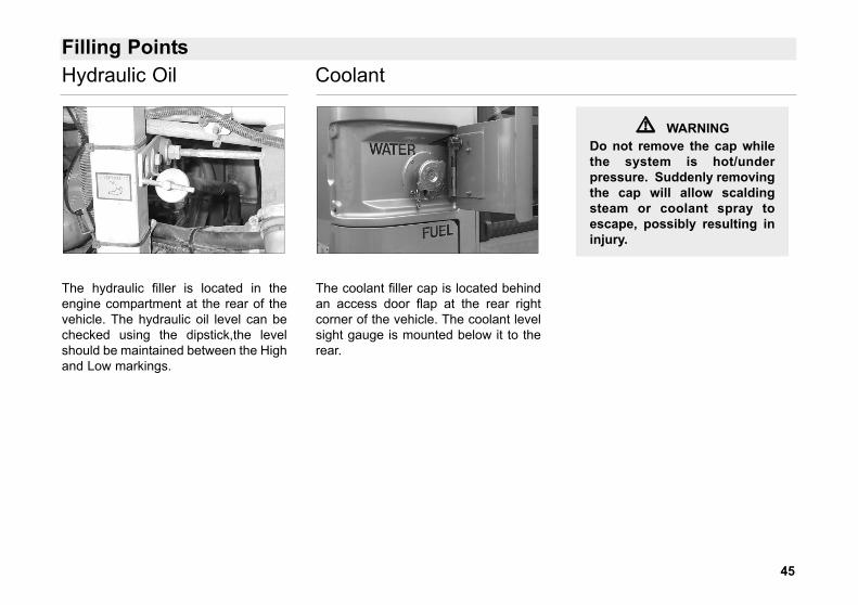
The hydraulic filler is located in theengine compartment at the rear of thevehicle. The hydraulic oil level can bechecked using the dipstick,the levelshould be maintained between the Highand Low markings.
The coolant filler cap is located behindan access door flap at the rear rightcorner of the vehicle. The coolant levelsight gauge is mounted below it to therear.
�� WARNINGDo not remove the cap whilethe system is hot/underpressure. Suddenly removingthe cap will allow scaldingsteam or coolant spray toescape, possibly resulting ininjury.
Hydraulic Oil Coolant
46
Posilock Refuelling
Refuelling Procedure
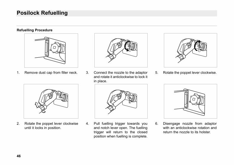
1. Remove dust cap from filler neck.
2. Rotate the poppet lever clockwiseuntil it locks in position.
3. Connect the nozzle to the adaptorand rotate it anticlockwise to lock itin place.
4. Pull fuelling trigger towards youand notch lever open. The fuellingtrigger will return to the closedposition when fuelling is complete.
5. Rotate the poppet lever clockwise.
6. Disengage nozzle from adaptorwith an anticlockwise rotation andreturn the nozzle to its holster.
47
Cleaning
Exterior Paintwork
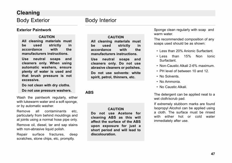
Wash the paintwork regularly, eitherwith lukewarm water and a soft sponge,or by automatic washer.Remove all contaminants etc,particularly from behind mouldings andat joints using a normal hose pipe only.Remove oil, diesel, tar and sap stainswith non-abrasive liquid polish.Repair surface fractures, deepscratches, stone chips, etc, promptly.
ABS
Sponge clean regularly with soap andwarm water.The recommended composition of anysoaps used should be as shown:
• Less than 20% Anionic Surfactant. • Less than 15% Non Ionic
Surfactant. • Non-Caustic Alkali 2-6% maximum. • PH level of between 10 and 12. • No Solvents. • No Ammonia. • No Caustic Alkali.
The detergent can be applied neat to awet cloth/scrub pad.If extremely stubborn marks are foundIsopropyl Alcohol can be applied usinga cloth. The surface must be rinsedwith either hot or cold waterimmediately after use.
CAUTIONDo not use Acetone forcleaning ABS as this willaffect the surface of the ABSupon exposure for just ashort period and will lead todiscolouration.
CAUTIONAll cleaning materials mustbe used strictly inaccordance with themanufacturers instructions.Use neutral soaps andcleaners only. Do not useabrasive cleaners or polishes.Do not use solvents: whitespirit, petrol, thinners, etc.
CAUTIONAll cleaning materials mustbe used strictly inaccordance with themanufacturers instructions.Use neutral soaps andcleaners only. When usingautomatic washers, ensureplenty of water is used andthat brush pressure is notexcessive.Do not clean with dry cloths.Do not use pressure washers.
Body Exterior Body Interior
48
Cleaning
MoquetteVacuum clean regularly. Removeheavy soiling with a stiff brush. Stainsshould be removed using a proprietarycleaning fluid.
PanellingSponge plastic laminate facings andpanels regularly with mild cleaningsolution and dry off with a leather.
FittingsWash chrome plated or aluminiumfittings approximately every two weekswith soap and water only.
FlooringRegular upkeep with suitable productsis the best guarantee that the flooringstays clean. The flooring’s cleaning willbe dictated by the intensity of traffic,climatic and environmental conditions.
Colour is an important factor, affectingthe level of cleaning required.
Dark Brown . . . . . . . . . . . .Very easy
Dark grey . . . . . . . . . . . . . .Easy care
Medium blue & grey . . .Moderate care
Beige, light grey . .Heavy care needed
A mop can be used for dailymaintenance and rising but alwaysensure the mop is rinsed in clean waterto prevent redistribution of dirt.
Cleaning agents should be used in theprescribed dilution relative to thedegree of soiling and, most importantlyin heavily soiled areas, the solutionshould be left on the floor for a fewminutes to take effect.
Flooring must be rinsed to ensurethorough removal of the cleaningagents’ residue, thus avoiding areduction in slip-resistance anddiscolouration of the flooring.
Irregular cleaning can result inproblems building up. For this reason,the importance of a regularprogramme, suited to the usage of thearea cannot be overstated. A typicalroutine could involve daily sweepingand damp mopping complemented byperiodic scrub cleaning.
High-pressure cleaners can be usedsuccessfully. However these arecomplicated to use and in view of thisand the variations caused by incorrectuse, serious deterioration may occur.For these reasons we absolutelyadvise against the use of this type ofequipment unless strict operatinginstructions are in place.
CAUTIONMoquette should be cleanedthoroughly to prevent a buildup of dust which could affectthe fire retardancy of theseating.
Body Interior
49
Cleaning
Flooring (continued)Examples of combined cleaningcycles:
• Aisles swept or vacuumedevery day.
• Aisles wet cleaned every week. • Major overall clean every three
months including treatment ofstains.
Detergent CompositionDetergent composition can vary widely.Alkaline detergents are best suited tothe cleaning of buses and they willgenerally deal with the majority of soils.
The composition of a cleaning productsuitable for cleaning the flooring on theEnviro 300 would be as follows: • Surfactant 2 - 7% w/w • Non-caustic alkali 2 - 6% w/w • *pH (conc) 12 - 13 • pH (10%w/w solution) 10 - 12 • Solvent: None • Caustic alkali: None
• Phosphate: None • Ammonia: None • Perfume: Optional
*PH 12 - 13 will give the best results,when correct dilution ratio is observed.care must be taken that the detergent isthoroughly removed in the rinsingoperation, otherwise this may lead tothe flooring performance beingdegraded.
RinsingCare must be taken to rinse the flooringthoroughly with hot or cold water.Vacuum or mop up excess water andallow to dry.
Dressing and PolishingTreating the flooring with metallisedemulsion is not recommended due tothe intensity of passenger traffic, it willwear off quickly and unevenly thuscreating unsightly patches on the floor.
Stain RemovalIn many cases a stronger concentrationof the maintenance detergent willremove stubborn stains. Where thestain is of a more permanent nature(i.e. graffiti or chewing gum) specialistproducts are available from mostchemical suppliers, however, it isalways sensible to check that hey arecompatible with the flooring beforeusing them.
TroubleshootingNew flooring becomes soiled after twoto three months despite cleaning:The choice of detergent is incorrect.
Gray streaks are left after cleaning:Ascertain whether the streaks are dueto soiling or detergent. If streaks aredue to soiling check that the detergentchoice and detergent dilution is correct.If the streaks are due to detergentresidues the rinsing may be inadequateor the detergent may being used at toohigh a concentration.
Body Interior

50
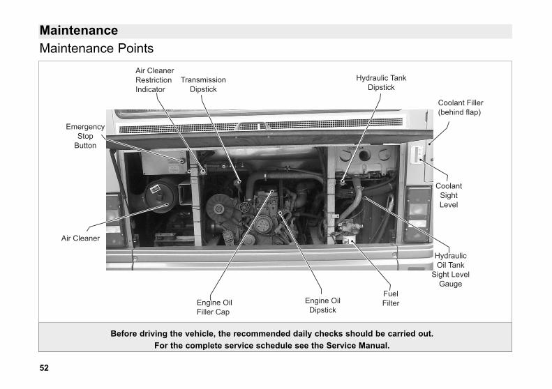
MaintenanceMaintenance Points
EmergencyStop
Button
Air Cleaner
Air CleanerRestrictionIndicator
Coolant Filler(behind flap)
Hydraulic TankDipstick
HydraulicOil Tank
Sight LevelGauge
Engine OilDipstick
Engine OilFiller Cap
CoolantSightLevel
TransmissionDipstick
FuelFilter
Before driving the vehicle, the recommended daily checks should be carried out.For the complete service schedule see the Service Manual.
51
Maintenance
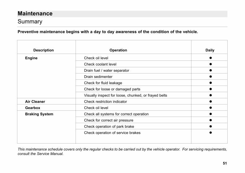
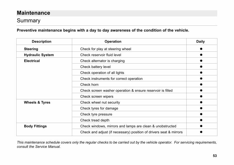
Preventive maintenance begins with a day to day awareness of the condition of the vehicle.
Summary
This maintenance schedule covers only the regular checks to be carried out by the vehicle operator. For servicing requirements,consult the Service Manual.
Description Operation Daily
Engine Check oil level
Check coolant level
Drain fuel / water separator
Drain sedimenter
Check for fluid leakage
Check for loose or damaged parts
Visually inspect for loose, chunked, or frayed belts
Air Cleaner Check restriction indicator
Gearbox Check oil level
Braking System Check all systems for correct operation
Check for correct air pressure
Check operation of park brake
Check operation of service brakes
52
MaintenanceMaintenance Points
EmergencyStop
Button
Air Cleaner
Air CleanerRestrictionIndicator
Coolant Filler(behind flap)
Hydraulic TankDipstick
HydraulicOil Tank
Sight LevelGauge
Engine OilDipstick
Engine OilFiller Cap
CoolantSightLevel
TransmissionDipstick
FuelFilter
Before driving the vehicle, the recommended daily checks should be carried out.For the complete service schedule see the Service Manual.
53
Description Operation Daily
Steering Check for play at steering wheel
Hydraulic System Check reservoir fluid level
Electrical Check alternator is charging
Check battery level
Check operation of all lights
Check instruments for correct operation
Check horn
Check screen washer operation & ensure reservoir is filled
Check screen wipers
Wheels & Tyres Check wheel nut security
Check tyres for damage
Check tyre pressure
Check tread depth
Body Fittings Check windows, mirrors and lamps are clean & unobstructed
Check and adjust (if necessary) position of drivers seat & mirrors
Maintenance
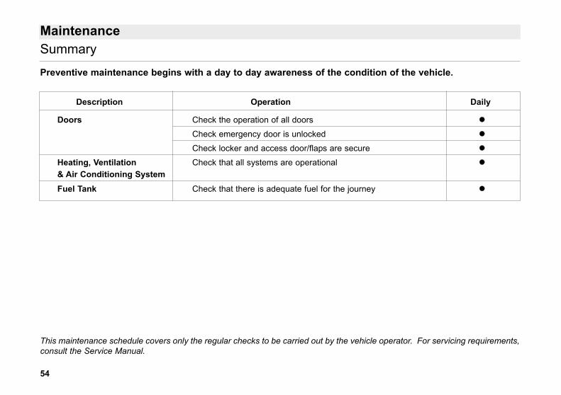
Preventive maintenance begins with a day to day awareness of the condition of the vehicle.
Summary
This maintenance schedule covers only the regular checks to be carried out by the vehicle operator. For servicing requirements,consult the Service Manual.
54
Description Operation Daily
Doors Check the operation of all doors
Check emergency door is unlocked
Check locker and access door/flaps are secure
Heating, Ventilation Check that all systems are operational& Air Conditioning SystemFuel Tank Check that there is adequate fuel for the journey
Maintenance
Preventive maintenance begins with a day to day awareness of the condition of the vehicle.
Summary
This maintenance schedule covers only the regular checks to be carried out by the vehicle operator. For servicing requirements,consult the Service Manual.
55
Maintenance
Corrosion InspectionWhen inspecting the underside of theVehicle or Bodywork view all theunderstructure which could holddirt/road salts. Also check damagedsurfaces for signs of bare metal.
Structural InspectionCheck the underside of the Bodyworkfor signs of loose mechanical fixing,cracks or weld failure of joints. On theexterior and interior, check for bulges orcracks on all joints and body structureintersections. Seats should also bechecked for cracks in pedestals and forsecurity on mountings.
Part AttachmentsCheck the security of pipes, cables,mudflaps, flooring, stepwells,handpoles, plus parts screwed, bolted,riveted or glued to the Bodywork.
Heating SystemCheck all pipe joints for signs ofweeping anti-freeze. Ensure gatevalves are capable of being turned onand off and are not leaking.
ElectricalInspect wiring for signs of chafing,discolouration of joints or damage toprotective covers.
Exterior Joints & GlazingCheck the glazing perimeter for signsof deterioration and possible waterleaks or failure of joint adhesion.
Paint FinishInspect the exterior surface for signs ofdeterioration in the form of blisters,scratching or minor damage, which ifnot rectified will result in majorproblems.
NOTEIt is important to act quickly inrectifying defects, asrecommended in the Servicemanual, since continuedrunning in a defectivecondition could result in rapiddeterioration.
Body Checks
56
Maintenance Checks
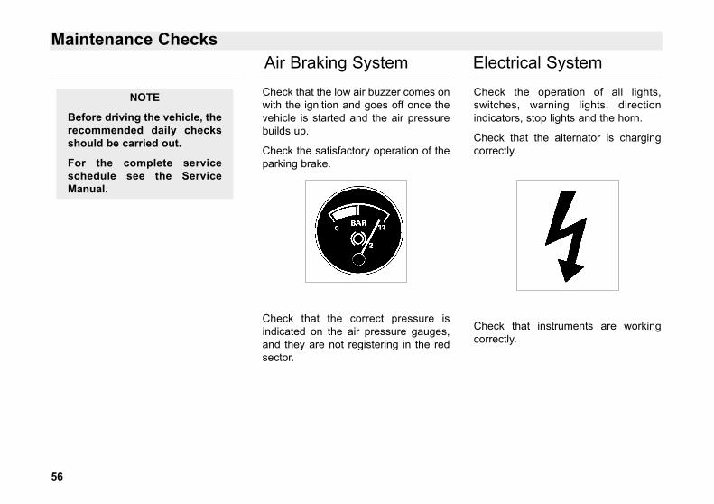
Check that the low air buzzer comes onwith the ignition and goes off once thevehicle is started and the air pressurebuilds up.
Check the satisfactory operation of theparking brake.
Check that the correct pressure isindicated on the air pressure gauges,and they are not registering in the redsector.
Check the operation of all lights,switches, warning lights, directionindicators, stop lights and the horn.
Check that the alternator is chargingcorrectly.
Check that instruments are workingcorrectly.
NOTE
Before driving the vehicle, therecommended daily checksshould be carried out.
For the complete serviceschedule see the ServiceManual.
Air Braking System Electrical System
57
Maintenance Checks
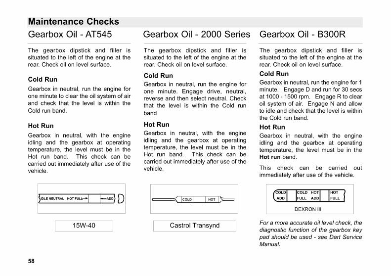
The hydraulic dipstick and filler issituated to the right of the engine on theframe upright.
The oil level should be checked withthe engine idling.
Maintain the level between the Highand Low marks.
The coolant level should be checkedwhen the engine is cold or after 15minutes if the vehicle has beenrunning.
If coolant needs adding, top up with50/50 mix of soft water/antifreezesolution.
The header tank filler cap is situated atthe rear right hand side of the vehicle.
The engine oil dipstick is situated at therear of the vehicle with the oil and fuelfillers.
The correct oil level should register onthe cross hatched area. Never operatethe engine with the oil level below thecross hatched area or above the fullmark.
FULL
NOTE
Wait at least five minutesafter stopping the engineto check the oil level, thisallows the oil to drain intothe sump.
�� WARNINGAllow the system to coolsufficIently before removingthe header tank filler cap asfaIlure to do so can causepersonal injury from heatedcoolant spray.
50% WATER+
50% ANTIFREEZE
LOW HIGH
Hydraulic System Cooling System Engine Oil Level
58
Maintenance Checks
The gearbox dipstick and filler issituated to the left of the engine at therear. Check oil on level surface.
Cold RunGearbox in neutral, run the engine forone minute to clear the oil system of airand check that the level is within theCold run band.
Hot RunGearbox in neutral, with the engineidling and the gearbox at operatingtemperature, the level must be in theHot run band. This check can becarried out immediately after use of thevehicle.
The gearbox dipstick and filler issituated to the left of the engine at therear. Check oil on level surface.
Cold RunGearbox in neutral, run the engine forone minute. Engage drive, neutral,reverse and then select neutral. Checkthat the level is within the Cold runband
Hot RunGearbox in neutral, with the engineidling and the gearbox at operatingtemperature, the level must be in theHot run band. This check can becarried out immediately after use of thevehicle.
The gearbox dipstick and filler issituated to the left of the engine at therear. Check oil on level surface.Cold RunGearbox in neutral, run the engine for 1minute. Engage D and run for 30 secsat 1000 - 1500 rpm. Engage R to clearoil system of air. Engage N and allowto idle and check that the level is withinthe Cold run band.Hot RunGearbox in neutral, with the engineidling and the gearbox at operatingtemperature, the level must be in theHot run band.
This check can be carried outimmediately after use of the vehicle.
For a more accurate oil level check, thediagnostic function of the gearbox keypad should be used - see Dart ServiceManual.
HOTFULL
COLDFULL
HOTADD
COLDADD
DEXRON III
Castrol Transynd
COLD HOT
15W-40
HOT FULL ADDIDLE NEUTRAL
Gearbox Oil - AT545 Gearbox Oil - 2000 Series Gearbox Oil - B300R
59
Maintenance Checks
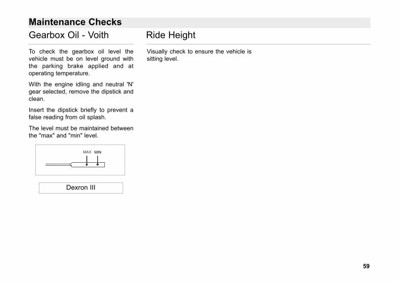
To check the gearbox oil level thevehicle must be on level ground withthe parking brake applied and atoperating temperature.
With the engine idling and neutral 'N'gear selected, remove the dipstick andclean.
Insert the dipstick briefly to prevent afalse reading from oil splash.
The level must be maintained betweenthe "max" and "min" level.
Visually check to ensure the vehicle issitting level.
Dexron III
MAX MIN
Gearbox Oil - Voith Ride Height
60
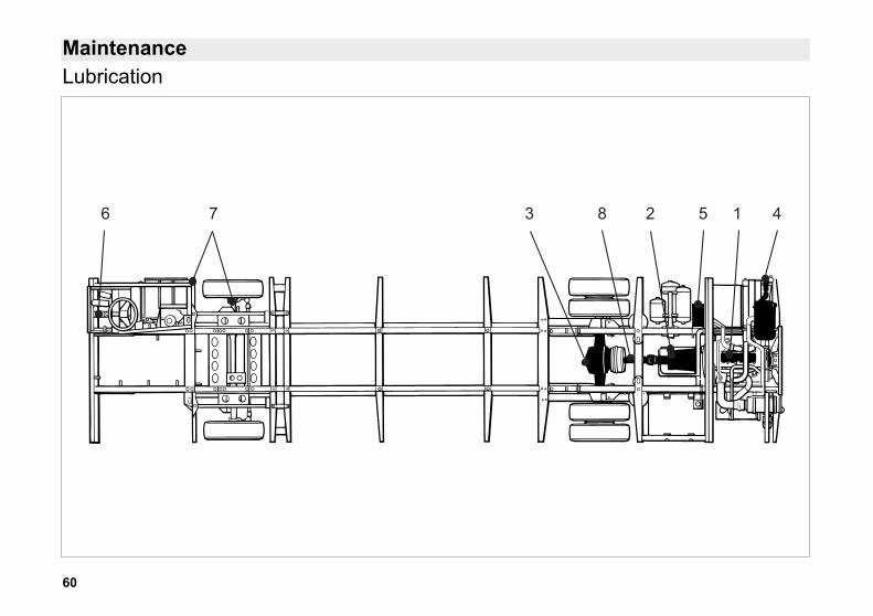
MaintenanceLubrication
6 7 3 8 2 5 1 4

61
MaintenanceLubrication Chart
Ref Vehicle Capacity Specification RecommendedNo Component in litres Brand
1 Engine 4 cylinder 11 API CG-4/SHEngine 6 cylinder 17.5 ACEA E5 15W/40 Texaco Ursa Super Premium*
CES 20077
2 Gearbox - Allison AT545Initial fill 18.9Oil change 15 API:CG-4/SH - SAE 15W/40 Texaco Ursa Super LA*Gearbox - Allison 2000 seriesInitial fill 14Oil change 10 Castrol Transynd Castrol TransyndGearbox - Allison B300RInitial fill 28.2Oil change 15.0 Dexron III Texamatic 7045*Gearbox - VoithInitial fill 25 - 28Oil change 23 - 26 Dexron III Texamatic 7045*
3 Rear Axle 4 cylinder 9.5 API-GL5 Texaco Geartex*Rear Axle 6 cylinder 18.7 85W/140 EPB 140
4 Cooling System 4 cylinder 20 Water/Antifreeze Texaco Havoline XLC*Cooling System 6 cylinder 22 50/50 Mix ASTM D 4985
5 Power Steering & Fan Drive system 16.5 Dexron IID or III Texamatic 7045*6 Steering Column Bevel Box 0.05 Dexron IID or III Texamatic 7045*
7 Grease: King pin swivels a/r Multipurpose Texaco Multifak EP2*Battery carrier pivot, steering relay shaft
8 Propshaft a/r Lithium Based Complex EP2 Texaco Hytex EP2*
* When using products other than those supplied by Texaco, consult your supplier to confirm compatibility
62
Emergency Repairs
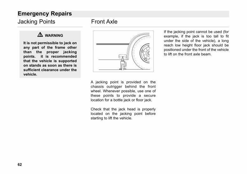
A jacking point is provided on thechassis outrigger behind the frontwheel. Whenever possible, use one ofthese points to provide a securelocation for a bottle jack or floor jack.
Check that the jack head is properlylocated on the jacking point beforestarting to lift the vehicle.
If the jacking point cannot be used (forexample, if the jack is too tall to fitunder the side of the vehicle), a longreach low height floor jack should bepositioned under the front of the vehicleto lift on the front axle beam.
�� WARNING
It is not permissible to jack onany part of the frame otherthan the proper jackingpoints. it is recommendedthat the vehicle is supportedon stands as soon as there issufficient clearance under thevehicle.
Jacking Points Front Axle
63
Emergency Repairs
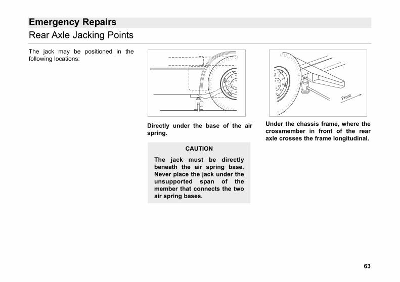
The jack may be positioned in thefollowing locations:
Directly under the base of the airspring.
Under the chassis frame, where thecrossmember in front of the rearaxle crosses the frame longitudinal.
Front
CAUTION
The jack must be directlybeneath the air spring base.Never place the jack under theunsupported span of themember that connects the twoair spring bases.
Rear Axle Jacking Points
64
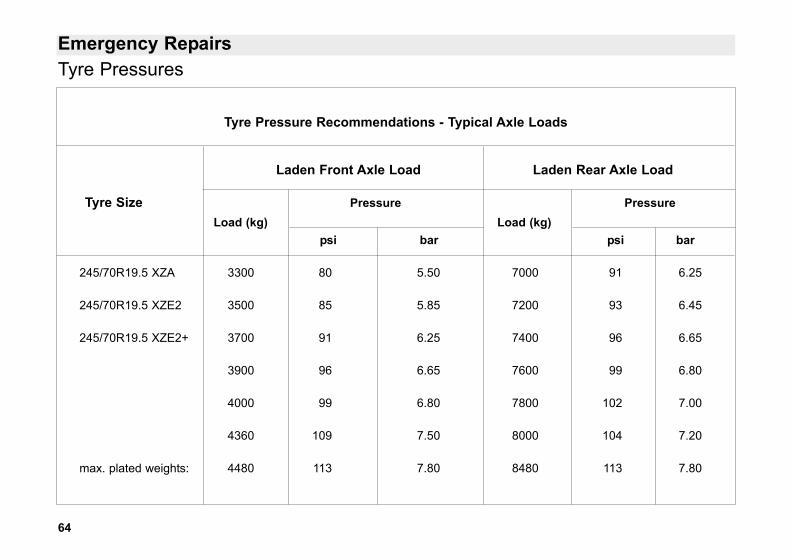
Emergency RepairsTyre Pressures
Tyre Pressure Recommendations - Typical Axle Loads
Laden Front Axle Load Laden Rear Axle Load
Tyre Size Pressure PressureLoad (kg) Load (kg)
psi bar psi bar
245/70R19.5 XZA 3300 80 5.50 7000 91 6.25
245/70R19.5 XZE2 3500 85 5.85 7200 93 6.45
245/70R19.5 XZE2+ 3700 91 6.25 7400 96 6.65
3900 96 6.65 7600 99 6.80
4000 99 6.80 7800 102 7.00
4360 109 7.50 8000 104 7.20
max. plated weights: 4480 113 7.80 8480 113 7.80
65
Emergency Repairs
Tyre pressures for any vehicle willdepend on its laden axle loadings. Thepressures can therefore only be finallydetermined by the bodybuilder, to takeaccount of varying body types,passenger weights etc.
The table on Page 64 gives thenominal pressures for a range of axleloadings and can be used as a basis fordetermining tyre pressures after ladenaxle weights have been established.
The pressures quoted have beendetermined to ensure an acceptablecompromise between ride comfort,handling, and tyre life. Reduction ofpressures below those identified forany given axle load is not permittedunless agreed by the tyremanufacturer. An increase of up to10% in front tyre pressures mayprovide improved front tyre life,particularly in urban conditions wheresharp corners or roundabouts arefrequently encountered. However, thisimproved life may be accompanied bya reduction in ride quality.
Increasing the rear tyre pressures inisolation is not permitted on rearengined bus applications, as handlingcould be adversely affected.
In case of doubt, reference should bemade to TransBus InternationalCustomer Care or the TechnicalDepartment of the tyre manufacturer.
Tyre Pressures
66
Emergency Repairs
Changing Road Wheels • Chock the wheels.
• Clean the wheel nuts and andcheck that the threads areundamaged.
• Jack up the axle, as close aspossible to the wheel to bechanged.
• Remove the wheel nuts andwheel.
• Clean the mating edges of thehub and the wheel. Apply a thincoat of water repellent greaseto the bore of the wheel.
• Check the the threads of thewheel studs are undamaged,clean and free from lubricant.
• The only lubricant permitted islight engine oil on the thread ofthe nut only.
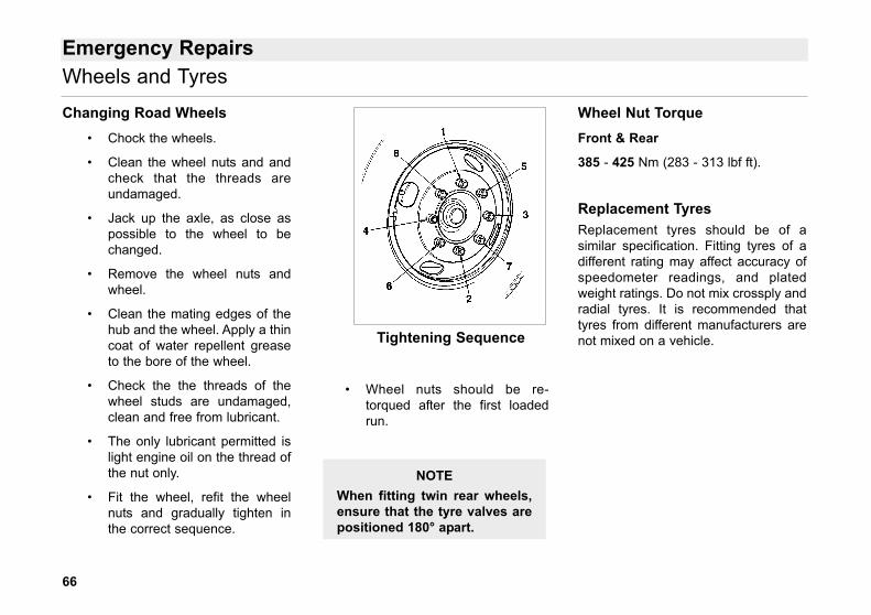
• Fit the wheel, refit the wheelnuts and gradually tighten inthe correct sequence.
• Wheel nuts should be re-torqued after the first loadedrun.
Wheel Nut TorqueFront & Rear
385 - 425 Nm (283 - 313 lbf ft).
Replacement TyresReplacement tyres should be of asimilar specification. Fitting tyres of adifferent rating may affect accuracy ofspeedometer readings, and platedweight ratings. Do not mix crossply andradial tyres. It is recommended thattyres from different manufacturers arenot mixed on a vehicle.
NOTEWhen fitting twin rear wheels,ensure that the tyre valves arepositioned 180° apart.
Wheels and Tyres
Tightening Sequence
67
Towing
The vehicle should be towed only fromthe towing eye. The towing eyesshould be screwed into both of thetapped sockets in the rear or frontcrossmember. A rigid tow bar shouldbe used, utilising both towing eyes.
An air coupling is located on the front ofthe vehicle to provide a means ofsupplying air to the braking systemwhile the vehicle is being towed.Where there is no means of supplyingair to the vehicle being towed theparking brake (spring brake) must bereleased.
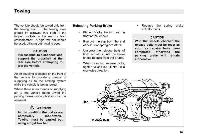
Releasing Parking Brake
• Place chocks behind and infront of the wheels.
• Remove the cap from the endof both rear spring actuators.
• Unscrew the release bolts ofboth actuators until the brakeshoes release from the drums.
• When resetting release bolts,tighten to 35ft lbs (47Nm) in aclockwise direction.
• Replace the spring brakeactuator caps.
CAUTIONWith the wheels chocked therelease bolts must be reset assoon as repairs have beencompleted otherwise theparking brake will remaininoperative.
CAUTIONIt is essential to disconnect andsupport the propshaft at therear axle before attempting totow the vehicle.
�� WARNINGIn this condition the brakes arecompletely inoperative.Towing must be carried outusing a rigid tow bar.
68
Alphabetical Index
AABS, 17
Accelerator Pedal, 26
Air Braking System Check, 56
Air Pressure Gauges, 13
Automatic Gearbox, 38, 39, 40
Automatic Gearbox Range Selector,23, 24
BBatteries & Carrier, 43
Brake Pedal, 26
Break Glass Hammer, 32
CCentre Door, 29
Centre Exit Door, 34
Cleaning, 47
Control Layout, 10
Controls, 23, 24, 25, 26, 27, 28
Coolant, 45
Cooling System Check, 57
CRT Exhaust, 36
DDirection Indicators, 22
Doors, 29
EElectrical System Check, 56
Emergency Engine Stop, 42
Emergency Exit Doors, 33, 34, 35
Engine, 36, 37
Engine Oil Level Check, 57
Engine Shutdown, 42
Engine stop, emergency, 42
FFire Extinguisher, 32
Fog Light, Rear, 13
Front Door, 29
Fuel Oil, 44
GGearbox Oil Check, 58, 59
HHazard Warning Switch, 13
Headlights, 22
Headlights Switch, 13
Heating & Ventilation, 20
Horn, 22
Hydraulic Oil, 45
Hydraulic System Check, 57
IIgnition Switch, 13
Instrument Panel, 12, 13
JJacking Points, 62, 63
LLubrication Chart, 61
Lubrication Points, 60
69
Alphabetical Index
MMain Door, 33
Maintenance Checks, Daily, 56, 57, 58,59
Maintenance Points, 50, 52
Master Switch, 13
Multi Function Switch, 21, 22
PParking Brake, 26
Passenger Stop Request, 18
Posilock Refuelling, 46
RRamp, 30
Range Inhibited Light, 13
Retarder, 41
Reverse Interlock, 24
Ride Height Check, 59
SSidelights Switch, 13
Speed Control Humps, 42
Steering Column, 25
Suspension Kneeling System, 28
Symbols, Key to, 4
TTowing, 67
Tyre Pressures, 64, 65
Tyres, 66
VVehicle Identification Plate, 8
Vehicle Identification Sheet, 9
Vehicle Lift System, 27
WWarning Lights, 14, 15, 16
Wheelchair Pasenger Request Stop, 18
Wheels, 66
Windscreen Wash, 21, 44
Windscreen Wipers, 21


TransBus International reserve the right to change the procedures, materials, specification, dimensions or designof the vehicle shown, described or referred to herein at any time and without prior notice in accordance with theCompany's policy of constant product improvement.