data center cooling modulesdocshare01.docshare.tips/files/11992/119922373.pdfdata center cooling...
TRANSCRIPT

Data CenterCoolingModules
www.ASTmodular.com

1
TABLEOF CONTENTS
Executive SummaryWorldwide PUEs Comparison Operational Expenditure & ROI Selection Guide & Features Real Projects
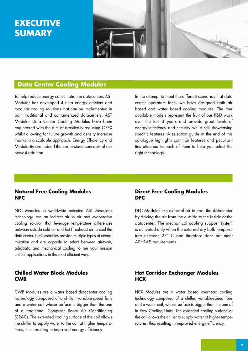
To help reduce energy consumption in datacenters AST Modular has developed 4 ultra energy efficient and modular cooling solutions that can be implemented in both traditional and containerized datacenters. AST Modular Data Center Cooling Modules have been engineered with the aim of drastically reducing OPEX whilst allowing for future growth and density increase thanks to a scalable approach. Energy Efficiency and Modularity are indeed the cornerstone concepts of our newest addition.
In the attempt to meet the different scenarios that data center operators face, we have designed both air based and water based cooling modules. The four available models represent the fruit of our R&D work over the last 3 years and provide great levels of energy efficiency and security whilst still showcasing specific features. A selection guide at the end of this catalogue highlights common features and peculiari-ties attached to each of them to help you select the right technology.
EXECUTIVE SUMARY
Natural Free Cooling ModulesNFC
NFC Modules, a worldwide patented AST Modular’s technology, are an indirect air to air and evaporative cooling solution that leverage temperature differences between outside cold air and hot IT exhaust air to cool the data center. NFC Modules provide multiple types of econo-mization and are capable to select between air-to-air, adiabatic and mechanical cooling to run your mission critical applications in the most efficient way.
Chilled Water Block ModulesCWB
CWB Modules are a water based datacenter cooling technology composed of a chiller, variable-speed fans and a water coil whose surface is bigger than the one of a traditional Computer Room Air Conditioning (CRAC). The extended cooling surface of the coil allows the chiller to supply water to the coil at higher tempera-tures, thus resulting in improved energy efficiency.
Direct Free Cooling ModulesDFC
DFC Modules use external air to cool the datacenter by driving the air from the outside to the inside of the datacenter. The mechanical cooling support system is activated only when the external dry bulb tempera-ture exceeds 27° C and therefore does not meet ASHRAE requirements
Hot Corridor Exchanger ModulesHCX
HCX Modules are a water based overhead cooling technology composed of a chiller, variable-speed fans and a water coil, whose surface is bigger than the one of In Row Cooling Units. The extended cooling surface of the coil allows the chiller to supply water at higher tempe-ratures, thus resulting in improved energy efficiency.
2
Data Center Cooling Modules

3
Energy consumption is a critical issue for IT organizations today, whether the goal is to reduce cost, protect the environment or to keep the datacenter up and running. According to Gartner, energy-related costs account for approximately 12% of overall data center expenditure and are the fastest-rising cost in the data center. Power cost problems are likely to worsen during the next few years as organizations grow their technology infrastructure , emerging from a recessionary period. Data Center inefficiencies threaten the profitability of business.
SCALABILITY ENABLING FUTURE GROWTH AND DENSITY INCREASENFC and DFC Modules feature 50 KW cooling capacity for each module whereas CWB are available in 100KW and 150KW models. Finally HCX can be purchased in the 7,5KW and 20KW version. Regardless of the different cooling capacity, all the cooling modules have been designed to easily scale along with your business needs, allowing for additional cooling capacity to be deployed quickly in a live environment and without disruption to the service. This results in minimizing capital expenditure and maximizing efficiency.
RIGHT SIZINGWhen the IT load is uncertain data center cooling systems are often oversized and operate inefficiently. Therefore, it makes sense to plan for modular growth of the cooling systems. AST Modular Cooling Modules allow you to avoid overbuilding in advance of actual needs and give your cooling infrastructure the flexibility needed in today’s economic climate.
SERVICEABILITY & LOW LEVEL OF MAINTENANCE NEEDED The specific design of AST Modular Cooling Modules makes them easy to maintain. Most of the modules feature an independent maintenance area, separeted from the IT space and maintainable without load interruption.
ADAPTABLE TO IT LOAD VARIATIONAST Modular’s Cooling Modules feature an accurate air management system that allows variable speed fans to match different server flow requirements. By constantly monitoring pressure and temperature the system ensures consistent and efficient cooling across various IT loads.
Advantages at a Glance
EXECUTIVE SUMARY
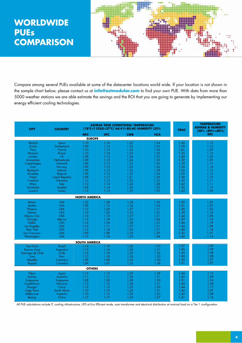
Compare among several PUEs available at some of the datacenter locations world wide. If your location is not shown in the sample chart below, please contact us at [email protected] to find your own PUE. With data from more than 5000 weather stations we are able estimate the savings and the ROI that you are going to generate by implementing our energy efficient cooling technologies.
4
WORLDWIDEPUEsCOMPARISON
CITY
MadridZurichParis
MoscowLondon
AmsterdamCopenhagen
OsloReykjavikBruxelles
PrahaFrankfurt
MilanStockholmIstanbul
MiamiSeattlePhoenixDenver
Mexico CityChicagoDallas
Los AngelesNew York
San FranciscoWashington
Sao PauloBuenos Aires
Santiago de ChileLima
MedellinBogotá
TokyoSydney
SingaporeCasablanca
ShangaiCape TownMelbourne
Beijing
All PUE calculations include IT, cooling infrastructure, UPS at Eco Efficient mode, auto transformer and electrical distribution at nominal load on a Tier 1 configuration
JapanAustralia
SingaporeMorocco
ChinaSouth Africa
AustraliaChina
1,131,111,281,121,151,101,121,17
1,251,261,281,261,251,251,261,24
1,331,311,301,311,331,311,301,27
BrazilArgentina
ChilePeru
ColombiaColombia
1,141,131,101,131,091,09
1,131,111,281,121,151,101,101,13
1,181,141,101,181,081,07
1,261,261,251,261,251,25
1,301,311,331,301,301,28
USAUSAUSAUSAUSA
MexicoUSAUSAUSAUSAUSA
1,231,091,131,101,101,121,161,101,121,091,13
1,281,121,261,201,101,181,241,111,181,081,16
1,281,241,271,231,271,231,281,271,231,251,25
1,301,341,311,351,311,261,321,311,271,291,28
SpainSwitzerland
FranceRussia
UKNetherlands
DenmarkNorwayIcelandBelgium
Czech RepublicGermany
ItalySwedenTurkey
1,101,091,101,101,091,091,091,091,091,091,091,121,121,091,12
1,161,151,131,161,131,121,131,151,151,151,171,151,141,141,13
1,251,231,241,221,241,241,231,221,221,221,211,221,241,201,25
1,341,351,341,351,351,351,361,361,381,261,251,251,281,231,29
COUNTRY
EUROPE
NORTH AMERICA
SOUTH AMERICA
OTHERS
ASHRAE 2008 CONDITIONS: TEMPERATURE(18ºC<T COLD<27ºC/ 64.4 F<80.6F) HUMIDITY (35%
NFC DFC CWB HCX
1,441,451,511,451,441,441,431,41
1,471,451,431,461,441,41
1,501,411,481,381,441,391,461,441,401,421,42
1,421,381,411,351,401,391,381,361,351,391,381,391,421,361,43
CRAC
1,151,091,341,081,171,071,081,16
1,091,091,081,081,071,07
1,221,091,201,181,081,141,181,081,141,071,14
1,121,121,091,151,091,091,101,141,131,101,131,111,111,121,09
TEMPERATUREASHRAE & HUMIDITY (20% <RH%<80%)
DFC

5
The BELOW OPEX Comparison is based on a 10 years period at 0,12 € / 0,12 $/Kwh and includes:
2. Maintenance Costs
3. UPS losses Transformers and Gesets on a TIER 3 configuration
1. Cooling Electrical Consumption
OPERATIONALEXPENDITURE& ROI
Equatorial LatitudesMid LatitudesHigh Latitudes
Equatorial LatitudesMid LatitudesHigh Latitudes
Equatorial LatitudesMid LatitudesHigh Latitudes
Equatorial LatitudesMid LatitudesHigh Latitudes
Equatorial LatitudesMid LatitudesHigh Latitudes
2.701.183 €2.460.166 €2.219.149 €
5.352.365 €4.870.332 €4.388.299 €
10.654.730 €9.690.664 €8.726.598 €
21.259.461 €19.331.328 €17.403.195 €
31.864.191 €28.971.992 €26.079.793 €
CracData Center Colocation
6.005.298 €5.737.390 €5.469.482 €
12.010.595 €11.474.779 €10.938.963 €
24.021.191 €22.949.559 €21.877.927 €
48.042.381 €45.899.118 €43.755.854 €
72.063.572 €68.848.676 €65.633.781 €
100 KW/T Load
200 KW/T Load
400 KW/T Load
800 KW/T Load
1200 KW/T Load
ROICWBHCX
2.572.622.78
1.892.022.33
1.461.411.75
1.411.361.70
1.361.311.65
ROINFCDFC
2.532.582.70
1.902.002.27
1.321.581.65
1.271.531.60
1.221.481.55
1.435.845 €1.363.540 €1.315.337 €
2.821.691 €2.677.081 €2.580.674 €
5.593.382 €5.304.162 €5.111.349 €
11.136.764 €10.558.324 €10.172.697 €
16.680.145 €15.812.486 €15.234.046 €
CWB-HCX
1.737.116 €1.616.608 €1.556.354 €
3.424.232 €3.183.216 €3.062.707 €
6.798.465 €6.316.432 €6.075.415 €
13.546.930 €12.582.863 €12.100.830 €
20.295.394 €18.849.295 €18.126.245 €
NFC-DFCEURO
Equatorial LatitudesMid LatitudesHigh Latitudes
Equatorial LatitudesMid LatitudesHigh Latitudes
Equatorial LatitudesMid LatitudesHigh Latitudes
Equatorial LatitudesMid LatitudesHigh Latitudes
Equatorial LatitudesMid LatitudesHigh Latitudes
3,522,880 $3,208,546 $2,894,212 $
6,980,550 $6,351,883 $5,723,216 $
13,895,890 $12,638,556 $11,381,222 $
27,726,573 $25,211,903 $22,697,234 $
41,557,254 $37,785,250 $34,013,246 $
CracData Center Colocation
7,832,105 $7,482,699 $7,133,294 $
15,664,209 $14,095,398 $14,266,587 $
31,328,419 $29,930,797 $28,533,176 $
62,656,837 $59,861,595 $57,066,352 $
93,985,257 $89,792,392 $85,599,528 $
100 KW/T Load
200 KW/T Load
400 KW/T Load
800 KW/T Load
1200 KW/T Load
ROICWBHCX
ROINFCDFC
2,265,545 $2,108,378 $2,029,795 $
4,465,880 $4,151,547 $3,994,380 $
8,866,553 $8,237,885 $7,923,551 $
17,667,896 $16,410,560 $15,781,893 $
26,469,237 $24,583,236 $23,640,235 $
CWB-HCX
7,294,884 $6,917,684 $6,666,217 $
1,872,627 $1,778,327 $1,715,461 $
3,680,047 $3,491,447 $3,365,713 $
14,524,559 $13,770,158 $13,267,223 $
21,754,232 $20,622,632 $19,868,231 $
NFC-DFCUS DOLLAR
2.572.622.78
1.892.022.33
1.461.411.75
1.411.361.70
1.361.311.65
2.532.582.70
1.902.002.27
1.321.581.65
1.271.531.60
1.221.481.55
6
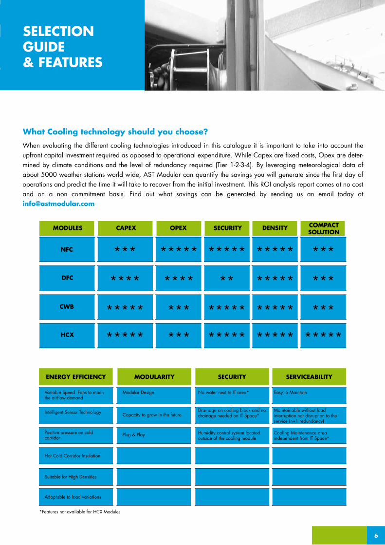
When evaluating the different cooling technologies introduced in this catalogue it is important to take into account the upfront capital investment required as opposed to operational expenditure. While Capex are fixed costs, Opex are deter-mined by climate conditions and the level of redundancy required (Tier 1-2-3-4). By leveraging meteorological data of about 5000 weather stations world wide, AST Modular can quantify the savings you will generate since the first day of operations and predict the time it will take to recover from the initial investment. This ROI analysis report comes at no cost and on a non commitment basis. Find out what savings can be generated by sending us an email today at [email protected]
SELECTION GUIDE& FEATURES
What Cooling technology should you choose?
***
****
*****
*****
*****
****
***
***
*****
**
*****
*****
*****
*****
*****
*****
DENSITY COMPACT SOLUTION
NFC
DFC
CWB
HCX
SECURITYOPEXCAPEXMODULES
***
***
***
*****
Variable Speed Fans to mach the airflow demand
Positive pressure on cold corridor
Hot Cold Corridor Insulation
Suitable for High Densities
Adaptable to load variations
Modular Design No water next to IT area*
Humidity control system located outside of the cooling module
Intelligent Sensor Technology Capacity to grow in the futureDrainage on cooling block and no drainage needed on IT Space*
Easy to Maintain
Cooling Maintenance area independent from IT Space*
Maintainable without load interruption nor disruption to the service (n+1 redundancy)
*Features not available for HCX Modules
ENERGY EFFICIENCY MODULARITY SECURITY SERVICEABILITY
Plug & Play

REAL PROJECTS
AST Modular promised our Tier 3 Data Center would run under an average yearly PUE of 1,09. We have been able to lower it down to 1,07. The energy efficiency, reliability and robustness of NFC is just amazing".
Arni Jonsson, CTO - THOR Data Center
NFC on a containerized installation in Sydney, Australia.
NFC Modules in a modular datacenter park in Brøndby, Denmark.

NATURAL FREE COOLING NFC
TECHNOLOGYNatural Free Cooling Modules, a worldwide patented AST Modular’s technology are an indirect air to air and evaporative cooling solution that leverage temperature differences between outside cold air and hot air coming out of the servers. Thanks to its heat pipe exchanger technology and the intelligent control system NFC Modules provide multiple types of economiza-tion. They are capable to select between air-to-air, adiabatic and mechanical cooling to run your mission critical applications in the most efficient way.
MULTI ECONOMIZATION EXPLAINEDNFC Modules capitalize free cooling at 100% with dry bulb temperatures below 20° C/68 F. They operate with adiabatic cooling with average wet bulb temperatures below 20 ° C/68 F and are supported by a chiller when ASHRAE’s temperature and humidity ranges cannot be met, specifically with wet bulb temperatures above 20° C/68 F. Unlike direct free cooling systems, NFC Modules are the first solution in the market able to prevent cross contamination and humidity within the datacenter. The exhaust air coming from the servers is cooled inside segregated chambers and no outdoor air is introduced into the IT space. As a result the datacenter remains as a sealed enclosure, unaffected by external conditions such as humidi-ty, pollution, corrosive gases, and particles. This approach drastically reduces filter, maintenance, and fan power costs, thus resulting in added security, resiliency and much better energy efficiency than direct free cooling technologies.
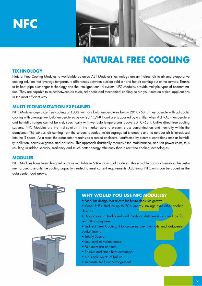
MODULESNFC Modules have been designed and are available in 50kw individual modules. This scalable approach enables the custo-mer to purchase only the cooling capacity needed to meet current requirements. Additional NFC units can be added as the data center load grows.
9
NFC
NATURAL FREE COOLING
WHY WOULD YOU USE NFC MODULES?• Modular design that allows for future densities growth.• Great PUEs. Reduce up to 70% energy savings over other cooling designs.• Applicable in traditional and modular datacenters as well as for retrofitting purposes.• Indirect Free Cooling. No concerns over humidity and datacenter contaminants.• Totally Secure.• Low level of maintenance.• Minimum use of filters.• Passive and static heat exchanger.• No single points of failure. • Accurate Air Flow Management.

Hot air coming from the Data Center is ducted into the Hot Chamber.
Cold air is blown into the external chamber without cross contamination between air flows.
Air economizer exchanges heat.
Cold air is recirculated into the cold corridor.
Hot air is exhausted outside of the NFC Module and reusable for different purposes.
1
2
3
4
5
1 2 3
4 5
10
OPERATION
ParisPUE 1.10
MoscowPUE 1.10
New YorkPUE 1.12
MiamiPUE 1.23
ChicagoPUE 1.12
Sao PauloPUE 1.14
Bueno AiresPUE 1.13
SydneyPUE 1.11
ShanghaiPUE 1.15
LondonPUE 1.09
1 2 3
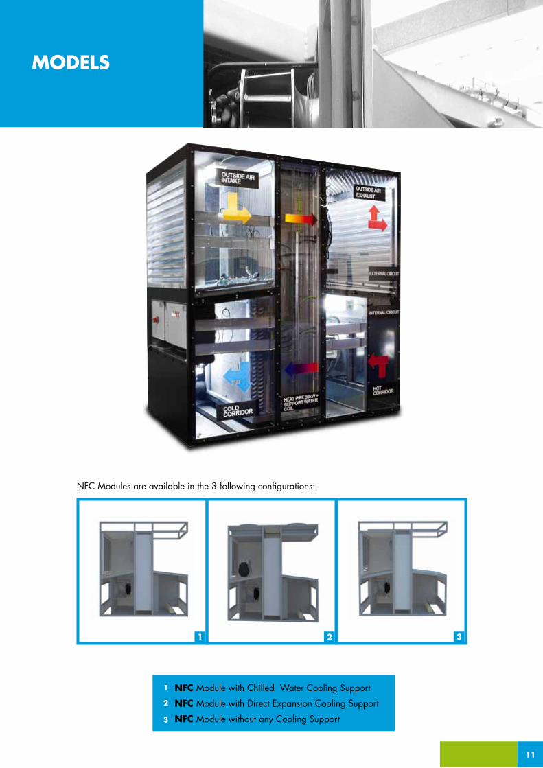
MODELS
NFC Modules are available in the 3 following configurations:
11
NFC Module with Chilled Water Cooling Support
NFC Module with Direct Expansion Cooling Support
NFC Module without any Cooling Support
1
2
3
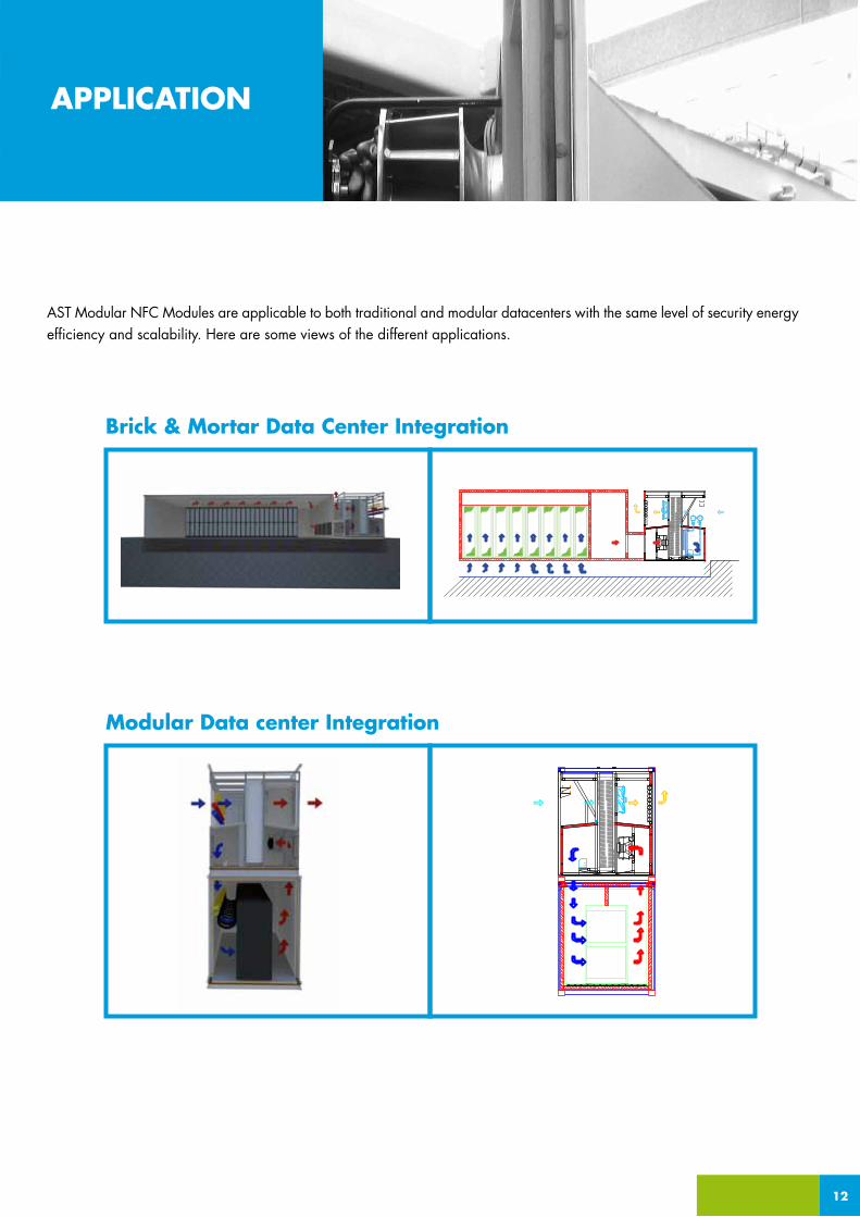
AST Modular NFC Modules are applicable to both traditional and modular datacenters with the same level of security energy efficiency and scalability. Here are some views of the different applications.
_APPLICATION
Brick & Mortar Data Center Integration
12
APPLICATION
Modular Data center Integration
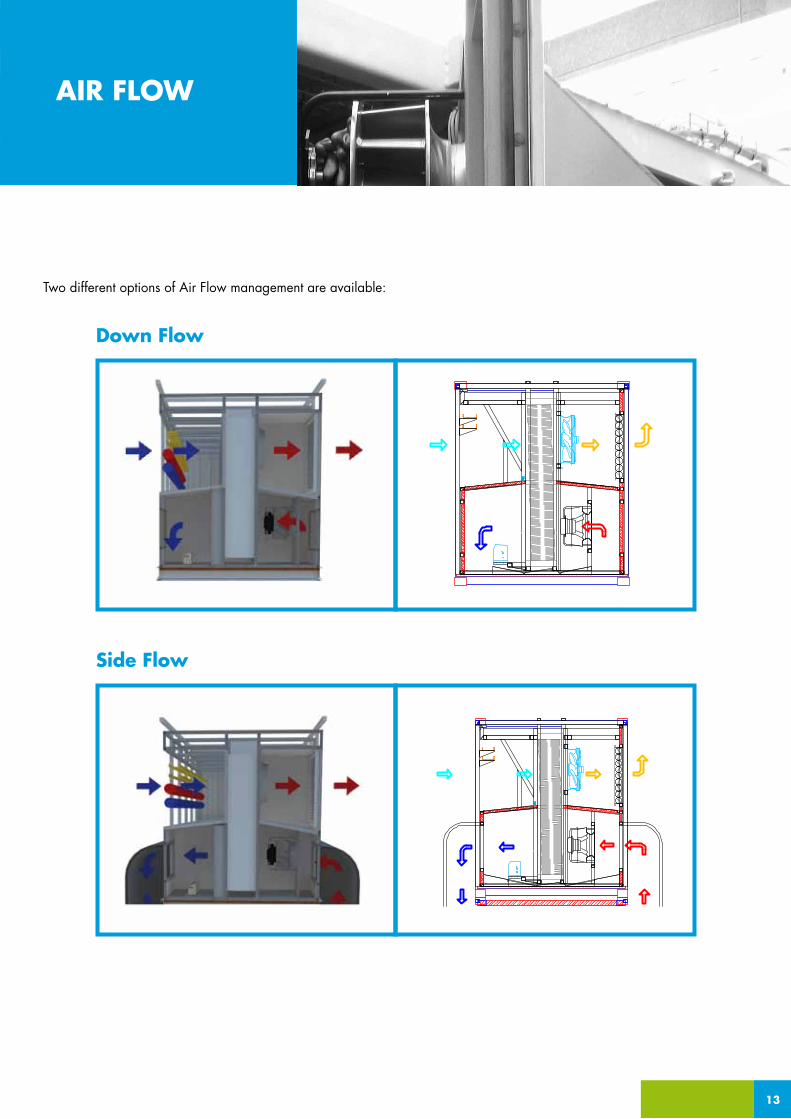
Two different options of Air Flow management are available:
_APPLICATION AIR FLOW
13
Side Flow
Down Flow

Module Maximum Cooling Power [kW] *
Number of internal Fans
OPTION 1: External Axial Fans
Internal Radial FanMaximum Airflow [m3/h] **
External Axial FanMaximum Airflow [m3/h] **
External Axial FanNominal Airflow [m3/h] **
Internal Radial FanNominal Airflow [m3/h] **
50
1
1
10.500 m3/h with 400 Pa available pressure
13.500 m3/h with 280 Pa total static pressure
11.000 m3/h with 200 Pa total static pressure
8.500 m3/h (@100CFM/kW) with 400 Pa available pressure
50
1
1
10.500 m3/h with 400 Pa available pressure
13.500 m3/h with 280 Pa total static pressure
11.000 m3/h with 200 Pa total static pressure
8.500 m3/h (@100CFM/kW) with 400 Pa available pressure
50
1
1
OPTION 2: External Radial Fans
1 1 1
Sound Pressure Level/ Nominal Airflow Lp [dBA]
72 dBA @ 3mts 72 dBA @ 3mts 72 dBA @ 3mts
Sound Pressure Level/ Nominal Airflow Lp [dBA]
63 dBA @ 3mts 63 dBA @ 3mts 63 dBA @ 3mts
Sound Pressure Level/ Nominal Airflow Lp [dBA]
70 dBA @ 3mts 70 dBA @ 3mts 70 dBA @ 3mts
Inlet Evaporating or CW coil temperatures
from 7ºC to 19ºC(if supplied by AST)
from 7ºC to 14ºC -
Number of Compressors Chiller to be supplied apart 1 -
Condeners Chiller to be supplied apart 2 with 2 fans -
Electrical Consumption at Nominal Cooling Power
3,6 kW NFC unit1,1 kW adiabatic system
3,6 kW NFC unit18 kW DX system 1,1 kW adiabatic system
3,6 kW NFC unit1,1 kW adiabatic system
Electrical Consumption at Maximum RPMs
4,6 kW NFC unit1,1 kW adiabatic system
4,6 kW NFC unit18 kW DX system1,1 kW adiabatic system
4,6 kW NFC unit1,1 kW adiabatic system
Dimensions (mm) 1.350 (W) X 2.300 (L) X 2.650 (H)
1.350 (W) X 2.300 (L) X 2.650 (H)
1.350 (W) X 2.300 (L) X 2.650 (H)
Weight [Kg]* Upon Data Center Conditions (see Cooling Power section)** Fan Data such as Consumption, RPM, etc. to be checked on Fans Technical Specs Sheet
1.150 1.485 1.065
Cooling Support Power [kW] 50 50 0
10.500 m3/h with 400 Pa available pressure
13.500 m3/h with 280 Pa total static pressure
Internal Radial FanMaximum Airflow [m3/h] **
10.500 m3/h with 400 Pa total static pressure
10.500 m3/h with 400 Pa total static pressure
10.500 m3/h with 400 Pa total static pressure
Internal Radial FanNominal Airflow [m3/h] **
8.500 m3/h with 400 Pa total static pressure
8.500 m3/h with 400 Pa total static pressure
8.500 m3/h with 400 Pa total static pressure
11.000 m3/h with 200 Pa total static pressure
8.500 m3/h (@100CFM/kW) with 400 Pa available pressure
NFC DX Cooling Support No Cooling SupportChilled Water Cooling Support
14
_APPLICATIONTECHNICALSPECIFICATIONS
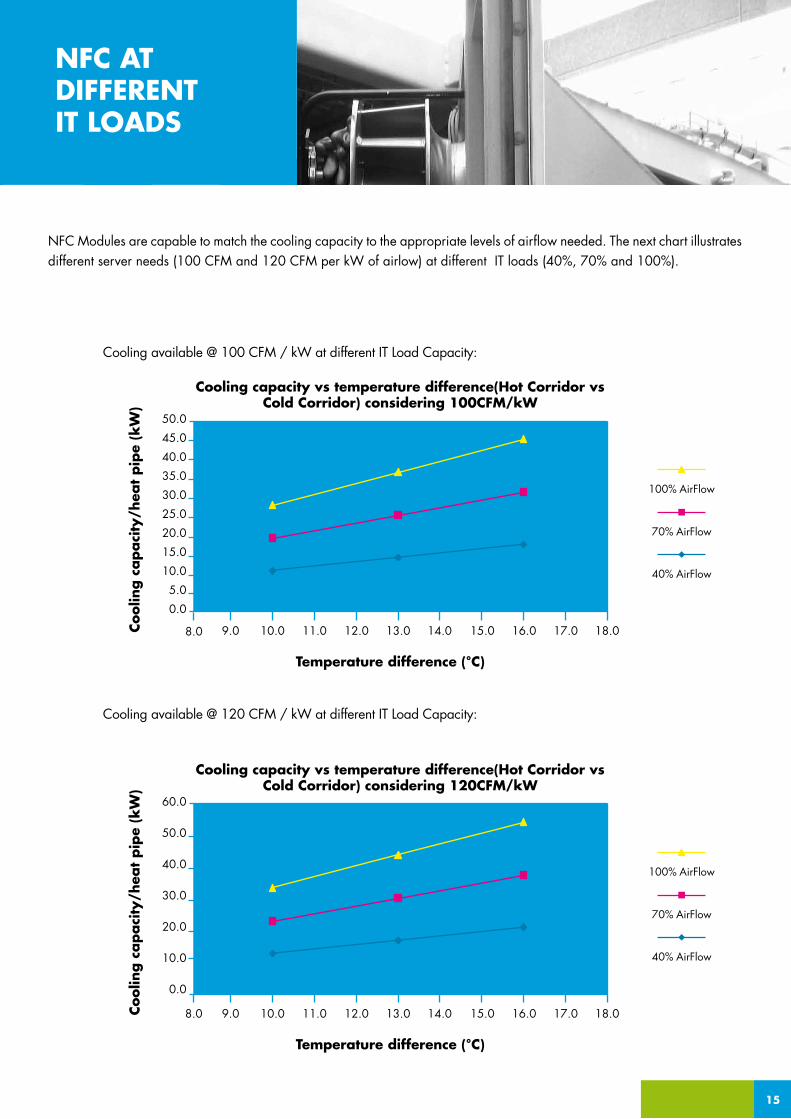
NFC Modules are capable to match the cooling capacity to the appropriate levels of airflow needed. The next chart illustrates different server needs (100 CFM and 120 CFM per kW of airlow) at different IT loads (40%, 70% and 100%).
Coolin
g c
apaci
ty/h
eat
pip
e (k
W)
Temperature difference (°C)
50.0
45.0
40.0
35.0
30.0
25.0
20.0
15.0
10.0
5.0
0.0
9.0 10.0 11.0 12.0 13.0 14.0 15.0 16.0 17.0 18.0
Cooling available @ 120 CFM / kW at different IT Load Capacity:
Cooling available @ 100 CFM / kW at different IT Load Capacity:
Cooling capacity vs temperature difference(Hot Corridor vs Cold Corridor) considering 100CFM/kW
70% AirFlow
40% AirFlow
100% AirFlow
Coolin
g c
apaci
ty/h
eat
pip
e (k
W)
Temperature difference (°C)
60.0
50.0
40.0
30.0
20.0
10.0
0.0
8.0 9.0 10.0 11.0 12.0 13.0 14.0 15.0 16.0 17.0 18.0
Cooling capacity vs temperature difference(Hot Corridor vs Cold Corridor) considering 120CFM/kW
70% AirFlow
40% AirFlow
100% AirFlow
15
8.0
NFC ATDIFFERENTIT LOADS
Appro
ach
Tem
per
atu
re (
T co
ld -
Tex
t)
Total DC Power Load (%)
08
07
06
05
04
03
02
01
00
100%
NFC Operational Range: Approach Temperatire vs DC Power Load
100 CFM/kW, Delta T= 12ºC
0%
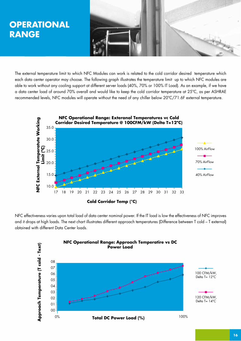
The external temperature limit to which NFC Modules can work is related to the cold corridor desired temperature which each data center operator may choose. The following graph illustrates the temperature limit up to which NFC modules are able to work without any cooling support at different server loads (40%, 70% or 100% IT Load). As an example, if we have a data center load of around 70% overall and would like to keep the cold corridor temperature at 25ºC, as per ASHRAE recommended levels, NFC modules will operate without the need of any chiller below 20ºC/71.6F external temperature.
120 CFM/kW, Delta T= 14ºC
16
OPERATIONALRANGE
NFC
Ex
tern
al T
emper
atu
te W
ork
ing
Lim
it (
ºC)
Cold Corridor Temp (°C)
35.0
30.0
25.0
20.0
15.0
10.0
17 18 19 20 21 22 23 24 25 26 27 28 29 30 31 32 33
NFC Operational Range: Exteranal Temperatures vc Cold Corridor Desired Temperature @ 100CFM/kW (Delta T=12ºC)
70% AirFlow
40% AirFlow
100% AirFlow
NFC effectiveness varies upon total load of data center nominal power. If the IT load is low the effectiveness of NFC improves and it drops at high loads. The next chart illustrates different approach temperatures (Difference between T cold – T external) obtained with different Data Center loads.
Total kW
Water: Tinlet
Water: Toutlet
Waterflow
Water: pressure drop
Airflow
Air: T/RH inlet
Air: T/RH outlet
Air: pressure drop
kW
ºC/F
ºC/F
lt/h
kPa
m3/h
ºC/%
ºC/%
Pa
58,5
12/53.6
17/62.6
10.065
16
9.680
39/22
21/60
91
55,1
14/57.2
19/66.2
9.477
14
9.680
39/22
22/57
90
52,4
17/62.6
22/71.6
9.004
12
9.680
39/22
24/50
93
43,2
19/66.2
24/75.2
7.429
8
9.680
39/22
26/44
93
NFC CW
Etylene glycol percent by weight (%)
Cooling capacity corr. factor
Power input corr. Factor
Mixture flow corr. Factor
Pressure drop corr. Factor
NFC DX available in Q2 2012
10%
0,986
1
1,023
1,061
20%
0,98
0,995
1,054
1,114
30%
0,973
0,99
1,092
1,19
40%
0,966
0,985
1,14
1,244
50%
0,96
0,975
1,2
1,31
Correction factors
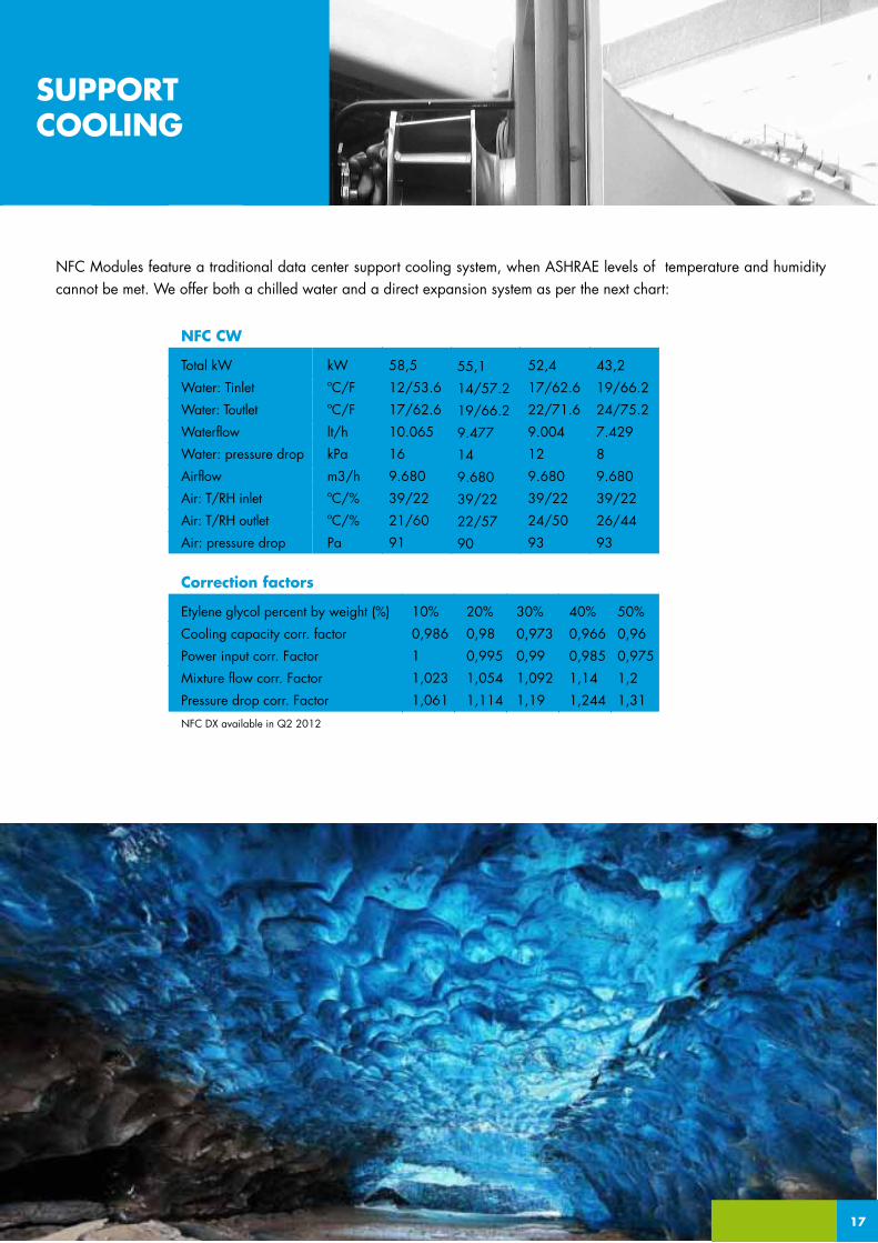
NFC Modules feature a traditional data center support cooling system, when ASHRAE levels of temperature and humidity cannot be met. We offer both a chilled water and a direct expansion system as per the next chart:
17
SUPPORTCOOLING

18
GeneralNumber of racks: 1 rackAtomization nozzles: 5 Rated atomization capacity: 4kg/h/nozzleTotal atomization capacity: 20 kg/h/block
Distribution systemPipe material: stainless steelConnection Stainless steel pipe external Ø 10 mm/ 0.4 inch
Pump assemblyPower supply: .EU: 230 Vac single-phase, 50 Hz / 400 Vac three-phase, 50 Hz .USA: 230 Vac single-phase, 60 Hz
Electrical consumption 1,15 kWWater inlet connections: Ø 1/4”G female / Ø 1/2”G emale depending on the model Water outlet connection: Ø 1/4”G female Water outlet pressure limits (bar) 20 to 80
Water supply conditionsTotal hardness (ppm CaCO3) 0 to 25 Conductivity limits (µS/cm) 30 to 50 µS/cmWater inlet pressure limits (bar) 3 to 8
Min 2% Slope in horizontal sections
BLOCK 2 BLOCK N
INOX Pipe 10-12 mmCabinet with
Thermic isolation
Vaporizer pumpThermic Resistance
with thermostat
Water Supply from water treatment system (reverse osmosis) not
suppliedBLOCK 1
Drainage
5 holesper line5 nozzles
NO
NO
Drainage Drainage
Drainage
5 holesper line5 nozzles
NO
NO
NO
NO
NONC
Filters
1um 5um
1um 5um
Data per Module
It is recommended to use a water treatment system such as a reverse osmosis unit with demineralizer (not included in AST Modular’s offer).Alternative Adiabatic system can be supplied without previous notice.
ADIABATICCOOLING
Evaporative cooling comes built into each module in order to leverage wet bulb temperatures. At certain locations where humidity levels are high, the adiabatic cooling systems can be optionally not included.
The system is composed of the following parts:
Rack with water atomization nozzles and electronic valves
High pressure connection pipes
Pump assembly with continuous modulation (inverter)
19
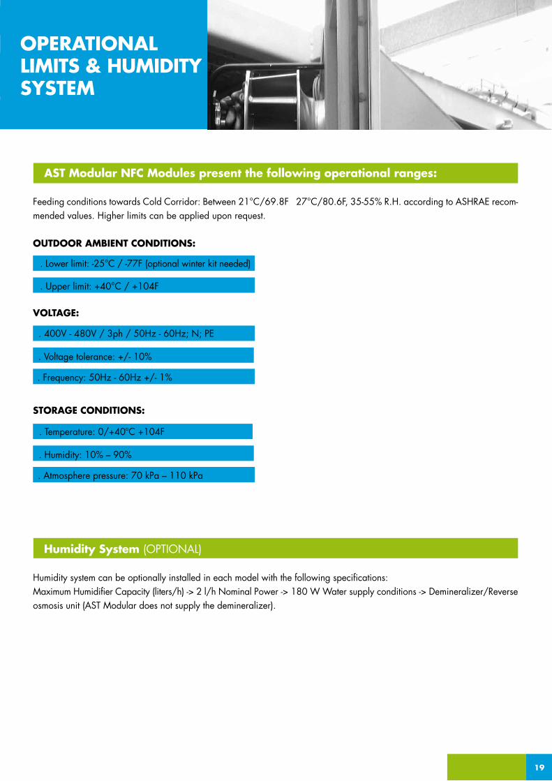
AST Modular NFC Modules present the following operational ranges:
Feeding conditions towards Cold Corridor: Between 21°C/69.8F 27°C/80.6F, 35-55% R.H. according to ASHRAE recom-mended values. Higher limits can be applied upon request.
OUTDOOR AMBIENT CONDITIONS:
VOLTAGE:
STORAGE CONDITIONS:
Humidity System (OPTIONAL)
Humidity system can be optionally installed in each model with the following specifications: Maximum Humidifier Capacity (liters/h) -> 2 l/h Nominal Power -> 180 W Water supply conditions -> Demineralizer/Reverse osmosis unit (AST Modular does not supply the demineralizer).
OPERATIONALLIMITS & HUMIDITYSYSTEM
. Lower limit: -25°C / -77F (optional winter kit needed)
. Upper limit: +40°C / +104F
. Voltage tolerance: +/- 10%
. Frequency: 50Hz - 60Hz +/- 1%
. 400V - 480V / 3ph / 50Hz - 60Hz; N; PE
. Humidity: 10% – 90%
. Atmosphere pressure: 70 kPa – 110 kPa
. Temperature: 0/+40ºC +104F

DIRECT FREE COOLING DFC
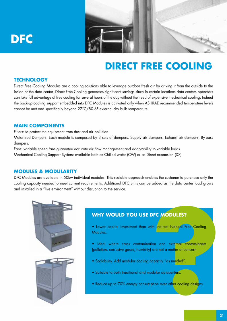
TECHNOLOGYDirect Free Cooling Modules are a cooling solutions able to leverage outdoor fresh air by driving it from the outside to the inside of the data center. Direct Free Cooling generates significant savings since in certain locations data centers operators can take full advantage of free cooling for several hours of the day without the need of expensive mechanical cooling. Indeed the back-up cooling support embedded into DFC Modules is activated only when ASHRAE recommended temperature levels cannot be met and specifically beyond 27°C/80.6F external dry bulb temperature.
MAIN COMPONENTSFilters: to protect the equipment from dust and air pollution.Motorized Dampers: Each module is composed by 3 sets of dampers. Supply air dampers, Exhaust air dampers, By-pass dampers.Fans: variable speed fans guarantee accurate air flow management and adaptability to variable loads.Mechanical Cooling Support System: available both as Chilled water (CW) or as Direct expansion (DX).
MODULES & MODULARITYDFC Modules are available in 50kw individual modules. This scalable approach enables the customer to purchase only the cooling capacity needed to meet current requirements. Additional DFC units can be added as the data center load grows and installed in a “live environment” without disruption to the service.
21
DFC
DIRECT FREE COOLING
WHY WOULD YOU USE DFC MODULES?
• Lower capital investment than with Indirect Natural Free Cooling Modules.
• Ideal where cross contamination and external contaminants (pollution, corrosive gases, humidity) are not a matter of concern.
• Scalability. Add modular cooling capacity “as needed”.
• Suitable to both traditional and modular datacenters.
• Reduce up to 70% energy consumption over other cooling designs.
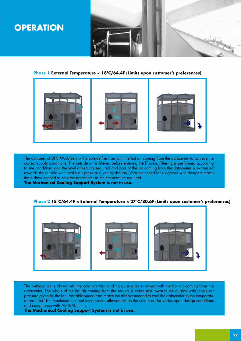
Phase 1 External Temperature < 18ºC/64.4F (Limits upon customer’s preferences)
The dampers of DFC Modules mix the outside fresh air with the hot air coming from the datacenter to achieve the correct supply conditions. The outside air is filtered before entering the IT area. Filtering is performed according to site conditions and the level of security required and part of the air coming from the datacenter is exhausted towards the outside with intake air pressure given by the fan. Variable speed fans together with dampers match the airflow needed to cool the datacenter to the temperature required.The Mechanical Cooling Support System is not in use.
Phase 2 18ºC/64.4F < External Temperature < 27ºC/80.6F (Limits upon customer’s preferences)
22
OPERATION
The outdoor air is blown into the cold corridor and no outside air is mixed with the hot air coming from the datacenter. The whole of the hot air coming from the servers is exhausted towards the outside with intake air pressure given by the fan. Variable speed fans match the airflow needed to cool the datacenter to the temperatu-re required. The maximum external temperature allowed inside the cold corridor varies upon design conditions and compliance with ASHRAE limits.The Mechanical Cooling Support System is not in use.

23
Phase 3 External Temperature > 27ºC/80.6F (Limits upon customer’s preferences)
No free cooling is available, hence the mechanical support cooling system is in use. The system recirculates the air from the hot to the cold corridor and cools down the servers to the desired temperature and upon design conditions.Two cooling systems are available: Chilled water (CW) or Direct expansion (DX). Variable speed fans match the airflow needed to cool the datacenter to the temperature required.The Mechanical Cooling Support System is in use.
OPERATION
ParisPUE 1.13
MoscowPUE 1.16
New YorkPUE 1.18
MiamiPUE 1.28
ChicagoPUE 1.18
Sao PauloPUE 1.18
Bueno AiresPUE 1.14
SydneyPUE 1.15
ShanghaiPUE 1.22
LondonPUE 1.13
1 2 3
MODELS
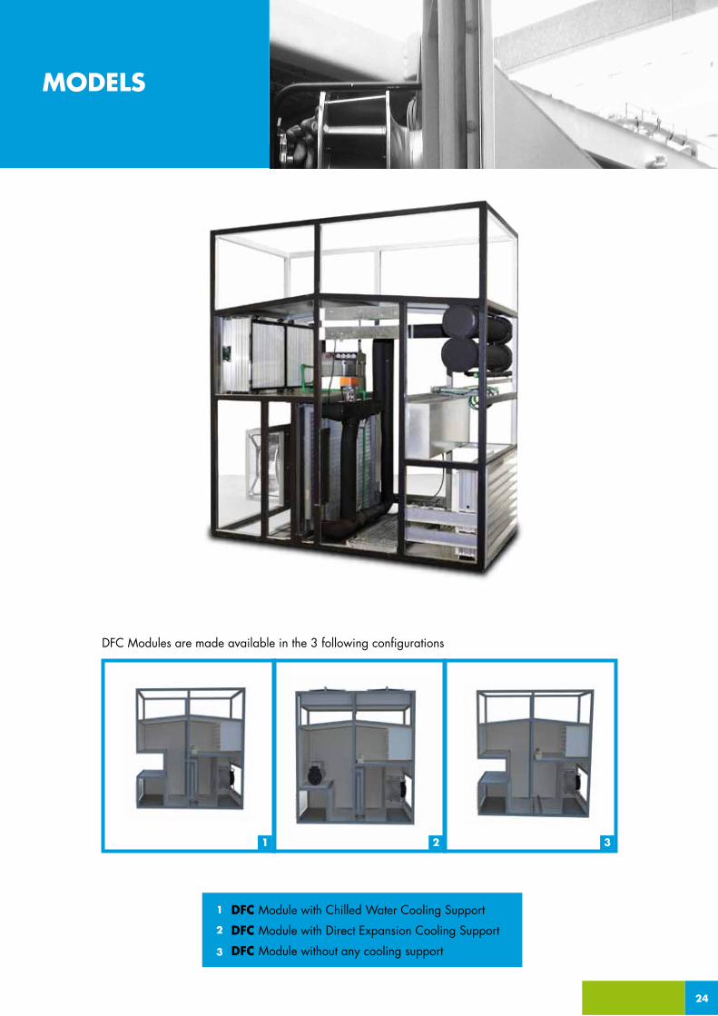
DFC Modules are made available in the 3 following configurations
24
DFC Module with Chilled Water Cooling Support
DFC Module with Direct Expansion Cooling Support
DFC Module without any cooling support
1
2
3
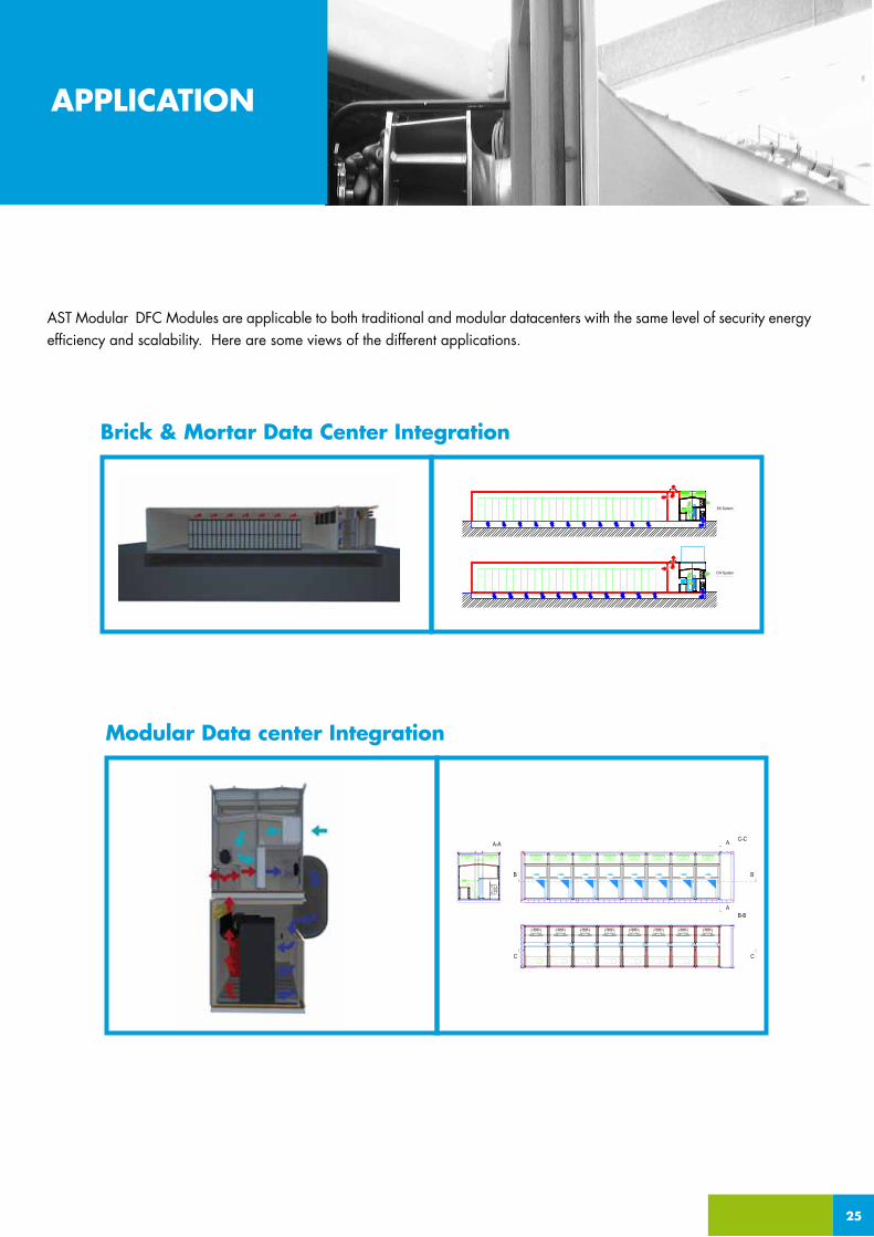
AST Modular DFC Modules are applicable to both traditional and modular datacenters with the same level of security energy efficiency and scalability. Here are some views of the different applications.
Brick & Mortar Data Center Integration
25
APPLICATION
Modular Data center Integration

Two different options of Air Flow management are available:
_APPLICATION AIR FLOW
26
Side Flow
Down Flow
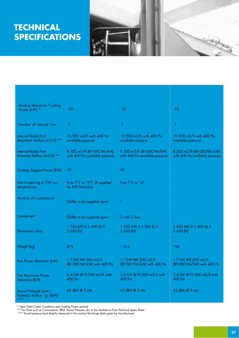
Module Maximum Cooling Power [kW] *
Number of internal Fans
Internal Radial FanMaximum Airflow [m3/h] **
Number of Compressors
Condensers
Dimensions (mm)
Weight (kg)
Fan Power Absortion (kW)
Fan Maximum PowerAbsortion (kW)
Internal Radial FanNominal Airflow [m3/h] **
Inlet Evaporing or CW coil temperatures
Cooling Support Power (kW)
50
1
10.500 m3/h with 400 Pa available pressure
50
from 7ºC to 19ºC (if supplied by AST Modular)
Chiller to be supplied apart
Chiller to be supplied apart
8.500 m3/h (@100CFM/kW) with 400 Pa available pressure
50
1
10.500 m3/h with 400 Pa available pressure
50
from 7ºC to 14º
1
2 with 2 fans
8.500 m3/h (@100CFM/kW) with 400 Pa available pressure
50
1
10.500 m3/h with 400 Pa available pressure
-
-
-
-
1,7 kW @8.500 m3/h (@100CFM/kW) with 400 Pa
1,7 kW @8.500 m3/h (@100CFM/kW) with 400 Pa
1,7 kW @8.500 m3/h (@100CFM/kW) with 400 Pa
2,4 kW @10.500 m3/h with 400 Pa
2,4 kW @10.500 m3/h with 400 Pa
2,4 kW @10.500 m3/h with 400 Pa
Sound Pressure Level / Nominal Airflow Lp [dBA] ***
* Upon Data Center Conditions (see Cooling Power section)** Fan Data such as Consumption, RPM, Sound Pressure, etc. to be checked on Fans Technical Specs Sheet *** Sound pressure level directly measured in fan suction/discharge (data given by manufacturer).
63 dBA @ 3 mts 63 dBA @ 3 mts 63 dBA @ 3 mts
1.350 (W) X 2.300 (L) X 2.650 (H)
1.350 (W) X 2.300 (L) X 2.650 (H)
1.350 (W) X 2.300 (L) X 2.650 (H)
875 1.210 790
8.500 m3/h (@100CFM/kW) with 400 Pa available pressure
DFC DX Cooling Support No Cooling SupportChilled Water Cooling Support
27
_APPLICATIONTECHNICALSPECIFICATIONS
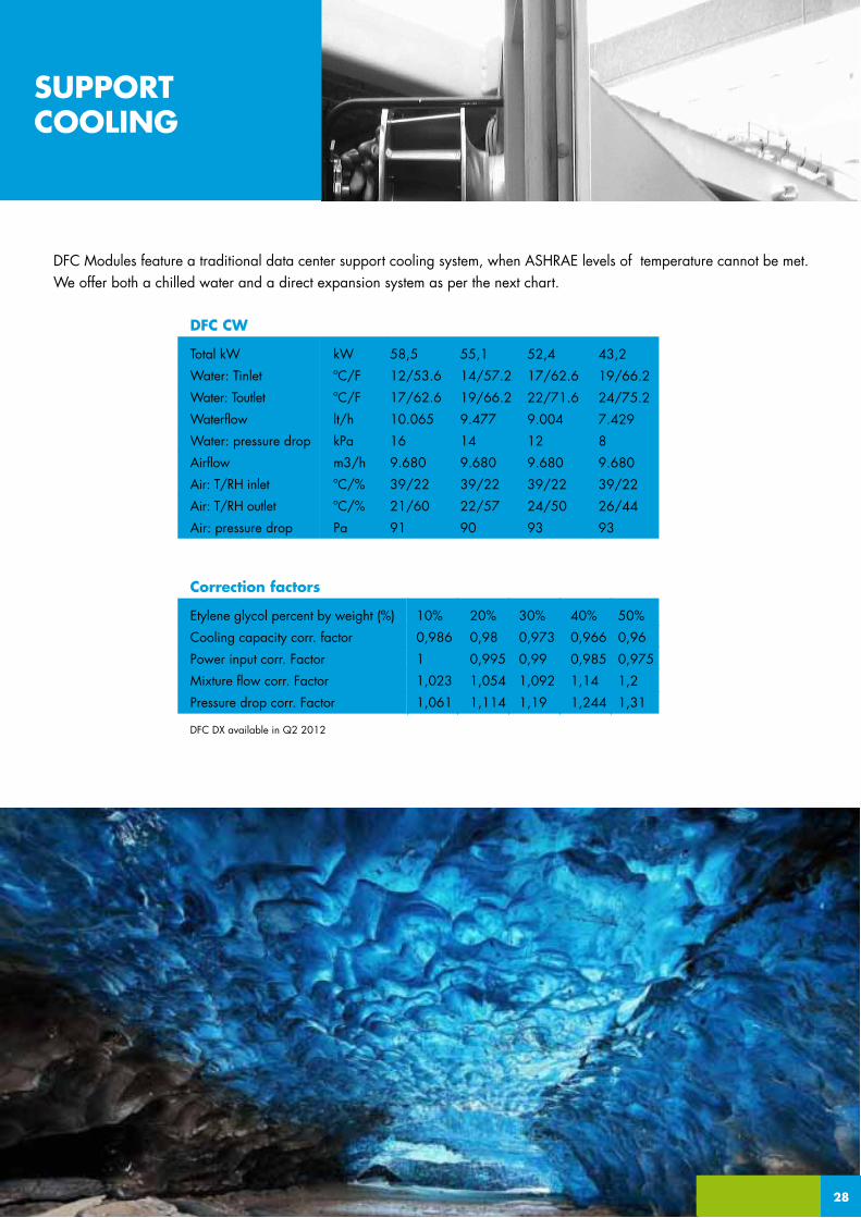
Total kW
Water: Tinlet
Water: Toutlet
Waterflow
Water: pressure drop
Airflow
Air: T/RH inlet
Air: T/RH outlet
Air: pressure drop
kW
ºC/F
ºC/F
lt/h
kPa
m3/h
ºC/%
ºC/%
Pa
58,5
12/53.6
17/62.6
10.065
16
9.680
39/22
21/60
91
55,1
14/57.2
19/66.2
9.477
14
9.680
39/22
22/57
90
52,4
17/62.6
22/71.6
9.004
12
9.680
39/22
24/50
93
43,2
19/66.2
24/75.2
7.429
8
9.680
39/22
26/44
93
DFC CW
Etylene glycol percent by weight (%)
Cooling capacity corr. factor
Power input corr. Factor
Mixture flow corr. Factor
Pressure drop corr. Factor
DFC DX available in Q2 2012
10%
0,986
1
1,023
1,061
20%
0,98
0,995
1,054
1,114
30%
0,973
0,99
1,092
1,19
40%
0,966
0,985
1,14
1,244
50%
0,96
0,975
1,2
1,31
Correction factors
DFC Modules feature a traditional data center support cooling system, when ASHRAE levels of temperature cannot be met. We offer both a chilled water and a direct expansion system as per the next chart.
16
SUPPORTCOOLING
28
29
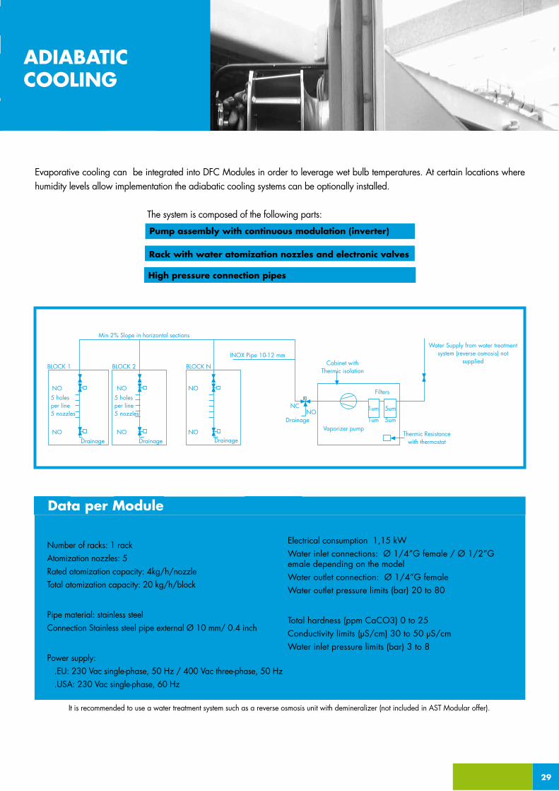
GeneralNumber of racks: 1 rackAtomization nozzles: 5 Rated atomization capacity: 4kg/h/nozzleTotal atomization capacity: 20 kg/h/block
Distribution systemPipe material: stainless steelConnection Stainless steel pipe external Ø 10 mm/ 0.4 inch
Pump assemblyPower supply: .EU: 230 Vac single-phase, 50 Hz / 400 Vac three-phase, 50 Hz .USA: 230 Vac single-phase, 60 Hz
Electrical consumption 1,15 kWWater inlet connections: Ø 1/4”G female / Ø 1/2”G emale depending on the model Water outlet connection: Ø 1/4”G female Water outlet pressure limits (bar) 20 to 80
Water supply conditionsTotal hardness (ppm CaCO3) 0 to 25 Conductivity limits (µS/cm) 30 to 50 µS/cmWater inlet pressure limits (bar) 3 to 8
Min 2% Slope in horizontal sections
BLOCK 2 BLOCK N
INOX Pipe 10-12 mmCabinet with
Thermic isolation
Vaporizer pumpThermic Resistance
with thermostat
Water Supply from water treatment system (reverse osmosis) not
suppliedBLOCK 1
Drainage
5 holesper line5 nozzles
NO
NO
Drainage Drainage
Drainage
5 holesper line5 nozzles
NO
NO
NO
NO
NONC
Filters
1um 5um
1um 5um
Data per Module
It is recommended to use a water treatment system such as a reverse osmosis unit with demineralizer (not included in AST Modular offer).
ADIABATICCOOLING
Evaporative cooling can be integrated into DFC Modules in order to leverage wet bulb temperatures. At certain locations where humidity levels allow implementation the adiabatic cooling systems can be optionally installed.
The system is composed of the following parts:
Rack with water atomization nozzles and electronic valves
High pressure connection pipes
Pump assembly with continuous modulation (inverter)
30
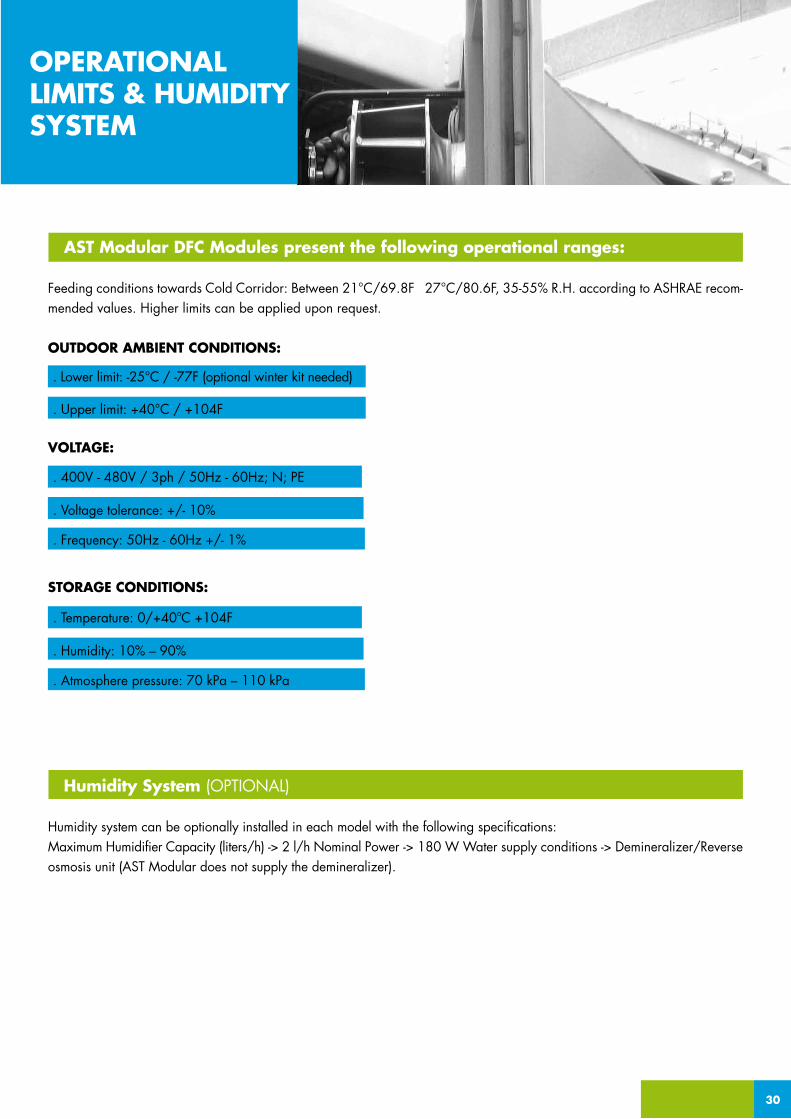
AST Modular DFC Modules present the following operational ranges:
Feeding conditions towards Cold Corridor: Between 21°C/69.8F 27°C/80.6F, 35-55% R.H. according to ASHRAE recom-mended values. Higher limits can be applied upon request.
OUTDOOR AMBIENT CONDITIONS:
VOLTAGE:
STORAGE CONDITIONS:
Humidity System (OPTIONAL)
Humidity system can be optionally installed in each model with the following specifications: Maximum Humidifier Capacity (liters/h) -> 2 l/h Nominal Power -> 180 W Water supply conditions -> Demineralizer/Reverse osmosis unit (AST Modular does not supply the demineralizer).
OPERATIONALLIMITS & HUMIDITYSYSTEM
. Lower limit: -25°C / -77F (optional winter kit needed)
. Upper limit: +40°C / +104F
. Voltage tolerance: +/- 10%
. Frequency: 50Hz - 60Hz +/- 1%
. 400V - 480V / 3ph / 50Hz - 60Hz; N; PE
. Humidity: 10% – 90%
. Atmosphere pressure: 70 kPa – 110 kPa
. Temperature: 0/+40ºC +104F

CHILLED WATER BLOCK CWB

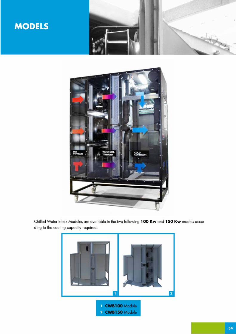
TECHNOLOGYChilled Water Block Modules are a water based datacenter cooling technology composed of a chiller, variable-speed fans and a water coil, whose surface is bigger than the one of a traditional Computer Room Air Conditioning (CRAC). The exten-ded cooling surface of the coil allows the chiller to supply water to the coil at higher temperatures thus resulting in improved energy efficiency.Dependent upon design conditions and desired cold corridor temperatures water can be supplied to temperatures up to 19°C/66.2F. External chiller is available as a free cooling chiller or as evaporative Cooling Tower.
MAIN COMPONENTSVariable Speed FansWater CoilFree cooling chiller or evaporative Cooling Tower (optional)Humidifier (optional)
MODULESCWB Modules are available in 100 KW and 150 KW models. This scalable approach enables the customer to purchase only the cooling capacity needed to meet current requirements. Additional CWB modules can be added as the data center load grows and installed in a ‘live environment’ without disruption to the service.
32
CWB
CHILLED WATER BLOCK
WHY WOULD YOU USE CW BLOCKS?
• Lower capital investment than with Indirect and Direct Free Cooling modules
• Scalability. Add modular cooling capacity “as needed”.
• Reduce up to 60% energy consumption over other cooling designs.
• Suitable to both traditional and modular datacenters.
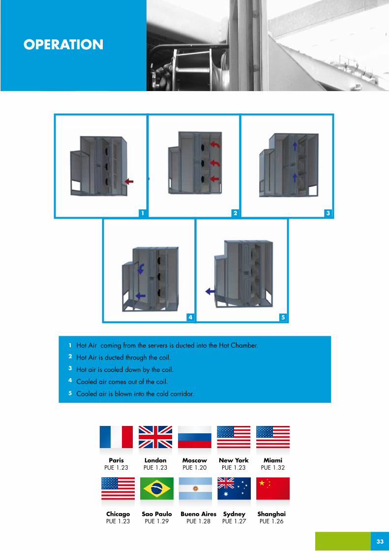
Hot Air coming from the servers is ducted into the Hot Chamber.
Hot Air is ducted through the coil.
Hot air is cooled down by the coil.
Cooled air comes out of the coil.
Cooled air is blown into the cold corridor.
1
2
3
4
5
1 2 3
4 5
33
OPERATION
ParisPUE 1.23
MoscowPUE 1.20
New YorkPUE 1.23
MiamiPUE 1.32
ChicagoPUE 1.23
Sao PauloPUE 1.29
Bueno AiresPUE 1.28
SydneyPUE 1.27
ShanghaiPUE 1.26
LondonPUE 1.23
1 2
MODELS
Chilled Water Block Modules are available in the two following 100 Kw and 150 Kw models accor-ding to the cooling capacity required:
34
CWB100 ModuleCWB150 Module
1
2
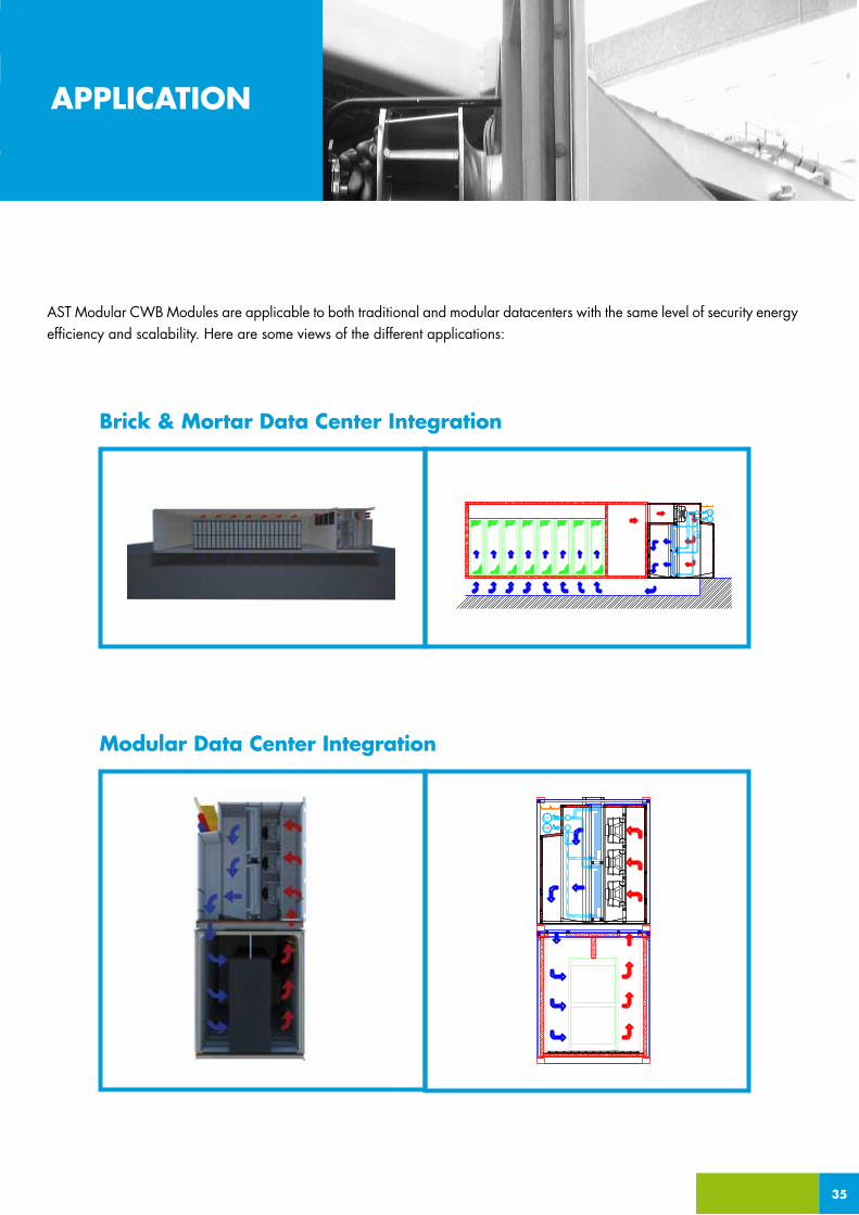
AST Modular CWB Modules are applicable to both traditional and modular datacenters with the same level of security energy efficiency and scalability. Here are some views of the different applications:
_APPLICATION
Brick & Mortar Data Center Integration
35
APPLICATION
Modular Data Center Integration
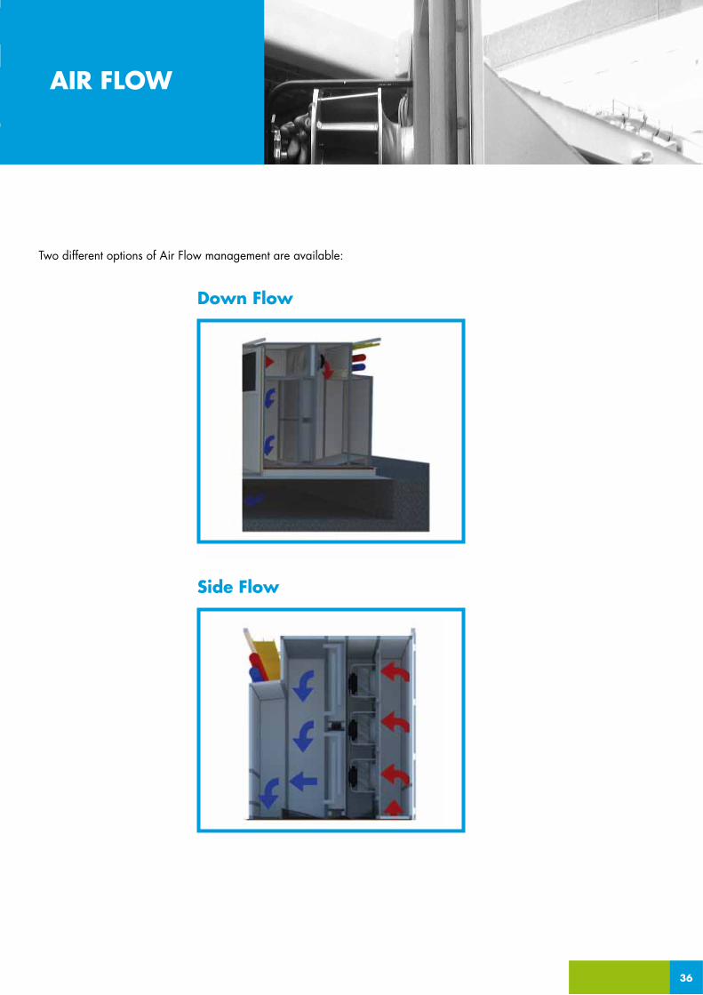
Two different options of Air Flow management are available:
_APPLICATION AIR FLOW
36
Side Flow
Down Flow
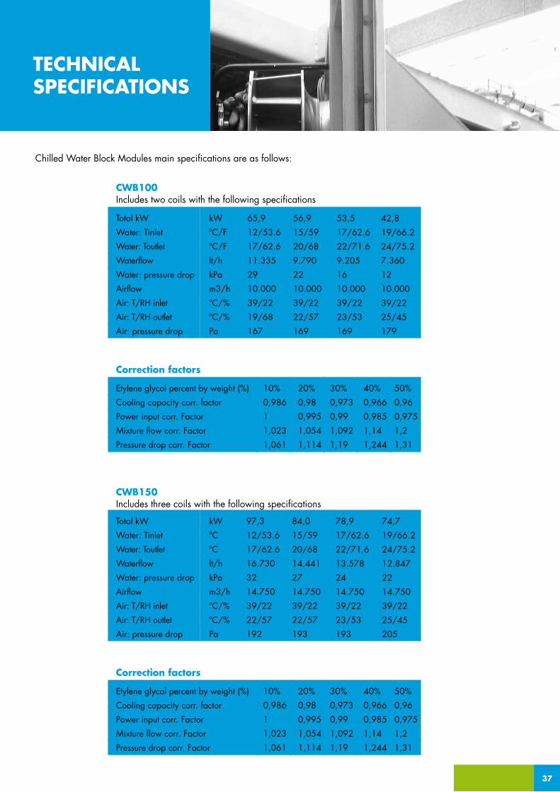
Chilled Water Block Modules main specifications are as follows:
Total kW
Water: Tinlet
Water: Toutlet
Waterflow
Water: pressure drop
Airflow
Air: T/RH inlet
Air: T/RH outlet
Air: pressure drop
kW
ºC/F
ºC/F
lt/h
kPa
m3/h
ºC/%
ºC/%
Pa
65,9
12/53.6
17/62.6
11.335
29
10.000
39/22
19/68
167
56,9
15/59
20/68
9.790
22
10.000
39/22
22/57
169
53,5
17/62.6
22/71.6
9.205
16
10.000
39/22
23/53
169
42,8
19/66.2
24/75.2
7.360
12
10.000
39/22
25/45
179
CWB100
Etylene glycol percent by weight (%)
Cooling capacity corr. factor
Power input corr. Factor
Mixture flow corr. Factor
Pressure drop corr. Factor
10%
0,986
1
1,023
1,061
20%
0,98
0,995
1,054
1,114
30%
0,973
0,99
1,092
1,19
40%
0,966
0,985
1,14
1,244
50%
0,96
0,975
1,2
1,31
Correction factors
Includes two coils with the following specifications
CWB150Includes three coils with the following specifications
Total kW
Water: Tinlet
Water: Toutlet
Waterflow
Water: pressure drop
Airflow
Air: T/RH inlet
Air: T/RH outlet
Air: pressure drop
kW
ºC
ºC
lt/h
kPa
m3/h
ºC/%
ºC/%
Pa
97,3
12/53.6
17/62.6
16.730
32
14.750
39/22
22/57
192
84,0
15/59
20/68
14.441
27
14.750
39/22
22/57
193
78,9
17/62.6
22/71.6
13.578
24
14.750
39/22
23/53
193
74,7
19/66.2
24/75.2
12.847
22
14.750
39/22
25/45
205
Etylene glycol percent by weight (%)
Cooling capacity corr. factor
Power input corr. Factor
Mixture flow corr. Factor
Pressure drop corr. Factor
10%
0,986
1
1,023
1,061
20%
0,98
0,995
1,054
1,114
30%
0,973
0,99
1,092
1,19
40%
0,966
0,985
1,14
1,244
50%
0,96
0,975
1,2
1,31
Correction factors
37
_APPLICATIONTECHNICALSPECIFICATIONS

38
AST Modular CWB Modules present the following operational ranges:
Feeding conditions towards Cold Corridor: Between 21°C/69.8F 27°C/80.6F, 35-55% R.H. according to ASHRAE recom-mended values. Higher limits can be applied upon request.
OUTDOOR AMBIENT CONDITIONS:
VOLTAGE:
STORAGE CONDITIONS:
Humidity System (OPTIONAL)
Humidity system can be optionally installed in each model with the following specifications: Maximum Humidifier Capacity (liters/h) -> 2 l/h Nominal Power -> 180 W Water supply conditions -> Demineralizer/Reverse osmosis unit (AST Modular does not supply the demineralizer).
OPERATIONALLIMITS & HUMIDITYSYSTEM
. Lower limit: 0 (winter kit optionally available)
. Upper limit: +40°C / +104F
. Voltage tolerance: +/- 10%
. Frequency: 50Hz - 60Hz +/- 1%
. 400V - 480V / 3ph / 50Hz - 60Hz; N; PE
. Humidity: 10% – 90%
. Atmosphere pressure: 70 kPa – 110 kPa
. Temperature: 0/+40ºC +104F

HOT CORRIDOR EXCHANGER HCX
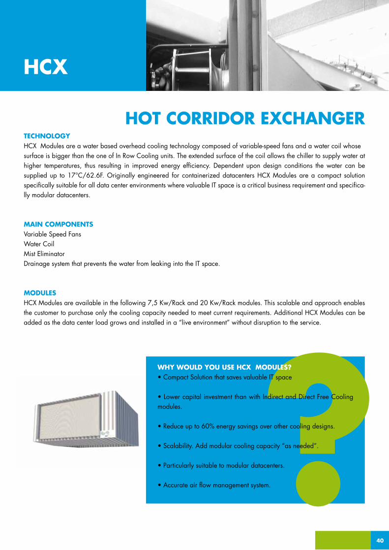
TECHNOLOGYHCX Modules are a water based overhead cooling technology composed of variable-speed fans and a water coil whosesurface is bigger than the one of In Row Cooling units. The extended surface of the coil allows the chiller to supply water at higher temperatures, thus resulting in improved energy efficiency. Dependent upon design conditions the water can be supplied up to 17°C/62.6F. Originally engineered for containerized datacenters HCX Modules are a compact solution specifically suitable for all data center environments where valuable IT space is a critical business requirement and specifica-lly modular datacenters.
MAIN COMPONENTSVariable Speed FansWater CoilMist EliminatorDrainage system that prevents the water from leaking into the IT space.
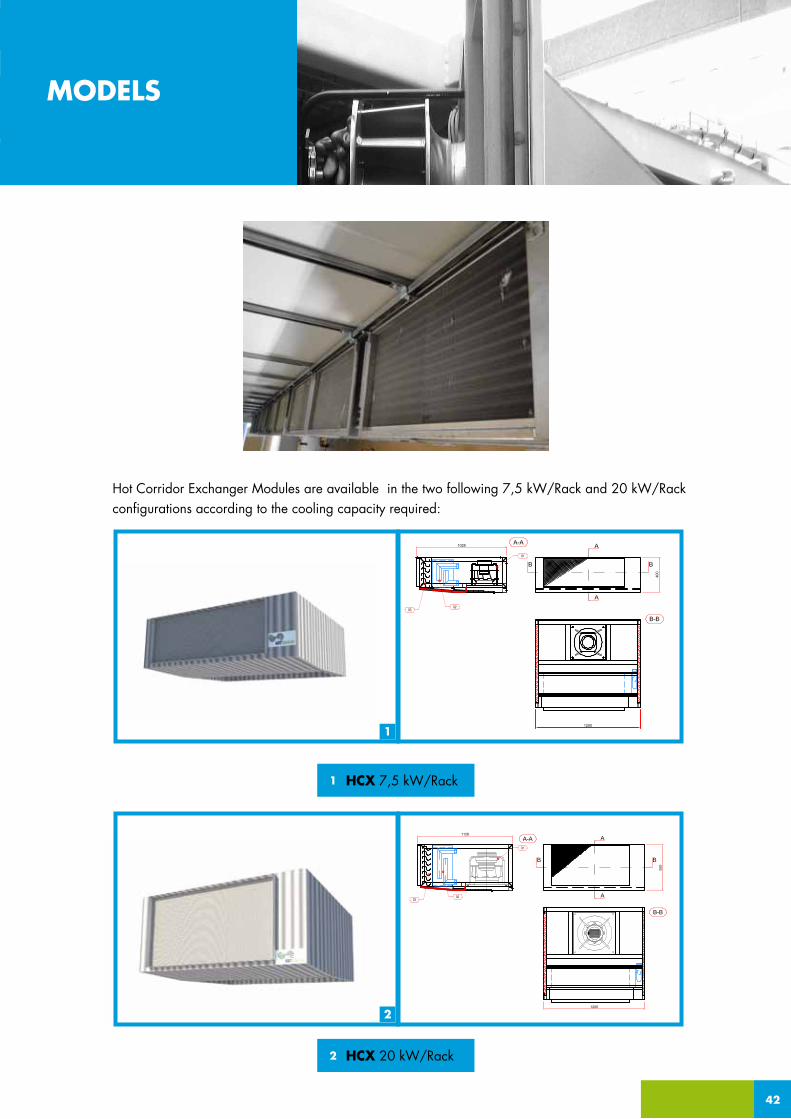
MODULESHCX Modules are available in the following 7,5 Kw/Rack and 20 Kw/Rack modules. This scalable and approach enables the customer to purchase only the cooling capacity needed to meet current requirements. Additional HCX Modules can be added as the data center load grows and installed in a “live environment” without disruption to the service.
40
HCX
HOT CORRIDOR EXCHANGER
WHY WOULD YOU USE HCX MODULES?• Compact Solution that saves valuable IT space
• Lower capital investment than with Indirect and Direct Free Cooling modules.
• Reduce up to 60% energy savings over other cooling designs.
• Scalability. Add modular cooling capacity “as needed”.
• Particularly suitable to modular datacenters.
• Accurate air flow management system.
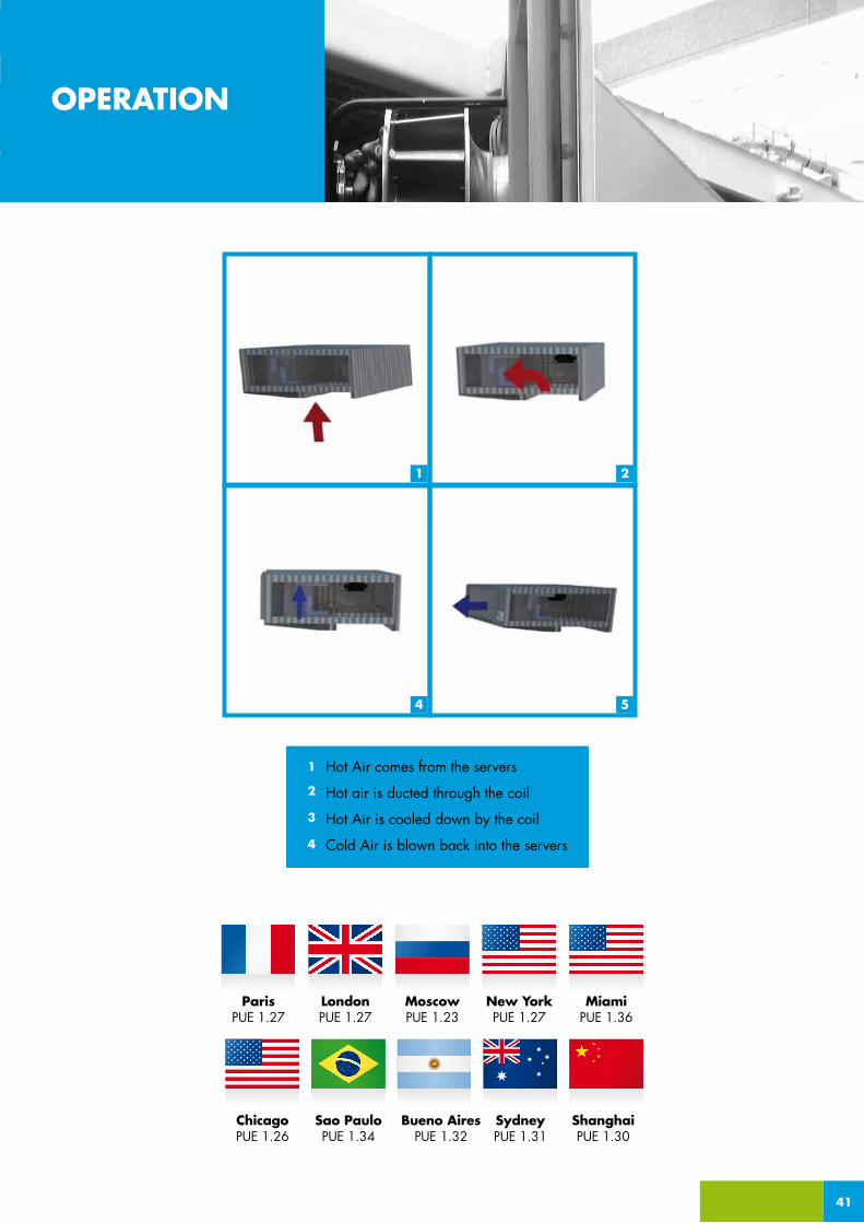
Hot Air comes from the servers
Hot air is ducted through the coil
Hot Air is cooled down by the coil
Cold Air is blown back into the servers
1
2
3
4
1 2
4 5
41
OPERATION
ParisPUE 1.27
MoscowPUE 1.23
New YorkPUE 1.27
MiamiPUE 1.36
ChicagoPUE 1.26
Sao PauloPUE 1.34
Bueno AiresPUE 1.32
SydneyPUE 1.31
ShanghaiPUE 1.30
LondonPUE 1.27
2
MODELS
1
Hot Corridor Exchanger Modules are available in the two following 7,5 kW/Rack and 20 kW/Rack configurations according to the cooling capacity required:
42
HCX 7,5 kW/Rack1
HCX 20 kW/Rack2
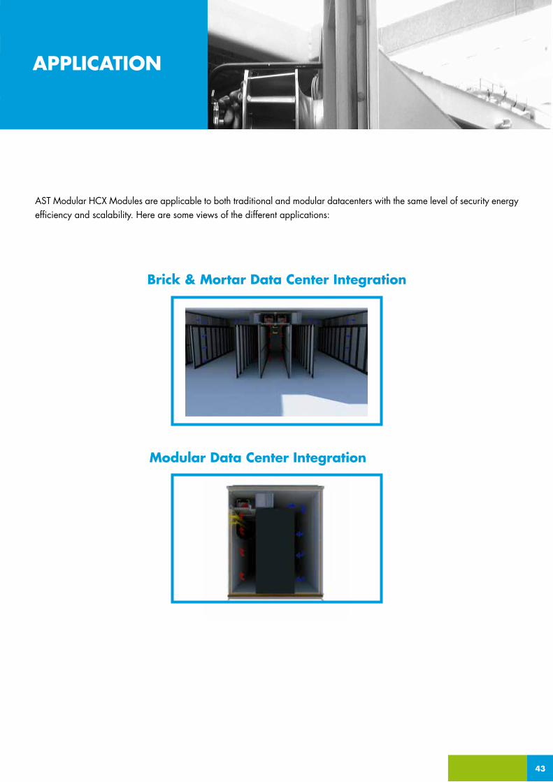
AST Modular HCX Modules are applicable to both traditional and modular datacenters with the same level of security energy efficiency and scalability. Here are some views of the different applications:
_APPLICATION
Brick & Mortar Data Center Integration
43
APPLICATION
Modular Data Center Integration

kW/rack
Total kW
Water: Tinlet
Water: Toutlet
Waterflow
Water: pressure drop
Airflow
Total available pressure per fan
Number of fans every 2 racks or 1 coil
Air: T/RH inlet
Air: T/RH outlet
Air: pressure drop
Noise
Weight
kW
kW
ºC/F
ºC/F
lt/h
kPa
m3/h
Pa
units
ºC/%
ºC/%
Pa
dB(A)
kg
7,5
14,9
7/44.6
12/53.6
2.568
18,0
2.600
300
1 unit
35,5/25
18/66
59
7,3
14,7
10/50
15/59
2.520
18,0
2.600
300
1 unit
35/25
20/55
64
7,5
15,4
12/53.6
17/62.6
2.654
18.0
2.600
300
1 unit
40/20
22/55
58
7,0
14,1
14/57.2
19/66.2
2.422
15,6
2.600
300
1 unit
40/20
24/50
59
HCX 7,5 Kw (CW)
Etylene glycol percent by weight (%)
Cooling capacity corr. factor
Power input corr. Factor
Mixture flow corr. Factor
Pressure drop corr. Factor
HCX DX available in Q2 2012
10%
0,986
1
1,023
1,061
20%
0,98
0,995
1,054
1,114
30%
0,973
0,99
1,092
1,19
40%
0,966
0,985
1,14
1,244
50%
0,96
0,975
1,2
1,31
Correction factors
kW/rack
Total kW
Water: Tinlet
Water: Toutlet
Waterflow
Water: pressure drop
Airflow
Total available pressure per fan
Number of fans every 2 racks or 1 coil
Air: T/RH inlet
Air: T/RH outlet
Air: pressure drop
Noise
Weight
kW
kW
ºC/F
ºC/F
lt/h
kPa
m3/h
Pa
units
ºC/%
ºC/%
Pa
dB(A)
kg
20
39,0
7/44.6
12/53.6
6.715
14,4
6.800
300
1 unit
35/25
18/66
234
19
38,3
10/50
15/59
6.591
12,9
6.800
300
1 unit
35/25
20/55
252
20
40,4
12/53.6
17/62.6
6.944
14,4
6.800
300
1 unit
40/20
22/55
232
18
36,7
14/57.2
19/66.2
6.316
12,9
6.800
300
1 unit
40/20
24/50
236
HCX 20 Kw (CW)
HCX Modules main specifications are as follows:
44
_APPLICATIONTECHNICALSPECIFICATIONS

45
AST Modular HCX Modules present the following operational ranges:
Feeding conditions towards Cold Corridor: Between 21°C/69.8F 27°C/80.6F, 35-55% R.H. according to ASHRAE recom-mended values. Higher limits can be applied upon request.
OUTDOOR AMBIENT CONDITIONS:
VOLTAGE:
STORAGE CONDITIONS:
Humidity System (OPTIONAL)
Humidity system can be optionally installed in each model with the following specifications: Maximum Humidifier Capacity (liters/h) -> 2 l/h Nominal Power -> 180 W Water supply conditions -> Demineralizer/Reverse osmosis unit (AST Modular does not supply the demineralizer).
OPERATIONALLIMITS & HUMIDITYSYSTEM
. Lower limit: 0 (winter kit optionally available)
. Upper limit: +40°C / +104F
. Voltage tolerance: +/- 10%
. Frequency: 50Hz - 60Hz +/- 1%
. 400V - 480V / 3ph / 50Hz - 60Hz; N; PE
. Humidity: 10% – 90%
. Atmosphere pressure: 70 kPa – 110 kPa
. Temperature: 0/+40ºC +104F

www.ASTmodular.com
Emea AST Modular Emea, 43 Albert Eisntein E-08940 Cornellà de Llobregat Barcelona, Spain, Tel.: +34 93 475 14 81,[email protected] America AST Modular North America, 15281 Northwest 33rd Place Opa-locka, FL 33054, US, Tel.: +1 954 753-4081, Mobile: +1 330 472 2800, [email protected], Souht America AST Modular Souht America, Rua Maestro João Gomes de Araújo, 106 Água Fria, 02332-020 - São Paulo - SP, Tel.: +55 11 2976 5701, Mobile: +55 11 9635 9051, [email protected]
AST Modular Cooling Modules’ Technical Specifications may suffer changes without previous notice.