data center segmentation design guide - cisco.com · importing a csv file containing static...
TRANSCRIPT
Software-Defined Segmentation for
the Data Center
TrustSec Data Center Segmentation Design Guide
Cisco Systems © 2016 Page 2
TrustSec Design Guide
Introduction .................................................................................................................................................... 5 About the TrustSec How-To Guides ............................................................................................................................................................................... 5 Business Drivers ........................................................................................................................................................................................................................ 5 TrustSec, an alternative method to traditional Data Center segmentation .............................................................................................. 6
Security Group Tags .................................................................................................................................................................................................... 6 TrustSec Fundamental Concepts ......................................................................................................................................................................... 7 Benefits of Using TrustSec to Enforce a Security Policy .......................................................................................................................... 8
Design Considerations .................................................................................................................................. 9 Data Center Architecture ....................................................................................................................................................................................................... 9
Implementation considerations ........................................................................................................................................................................... 10 Data Center Classification ..................................................................................................................................................................................... 10
Device SGT Classification ............................................................................................................................................................................... 12 Classification via Port Profile on Nexus 7000 and Nexus 1000V ................................................................................................ 12 Classification via Port to SGT assignment .............................................................................................................................................. 13
Nexus 6000/5600/5500 ............................................................................................................................................................................... 13 Nexus 7000 ........................................................................................................................................................................................................ 14 Summary of port-level Classification .................................................................................................................................................... 15
VLAN to SGT Classification and the Nexus 7000 ............................................................................................................................... 15 IP to SGT classification on the Nexus Switches .................................................................................................................................. 16
Nexus 7000 and IP-SGT ............................................................................................................................................................................. 17 Nexus 6000/5600/5500 and IP-SGT .................................................................................................................................................... 18 Nexus 1000 and IP-SGT ............................................................................................................................................................................. 18
IP to SGT classification at the Identity services Engine ................................................................................................................... 19 IP to SGT classification and the ASA ......................................................................................................................................................... 19 NX-OS Classification Priority .......................................................................................................................................................................... 19 IP-SGT Scaling ...................................................................................................................................................................................................... 20
Data Center Security Group Tag Propagation ............................................................................................................................................ 21 Inline Tagging in the Data Center ................................................................................................................................................................ 21
Nexus Data Center Switches and ASA with Inline Tagging ..................................................................................................... 21 Port Channels and CTS (Inline Tagging) ........................................................................................................................................... 23 Nexus 7000 F3 Linecard ............................................................................................................................................................................. 23 Nexus 1000V and CTS ................................................................................................................................................................................ 23 UCS Fabric Interconnects and Extenders ......................................................................................................................................... 23 ASA inline tagging considerations ......................................................................................................................................................... 24 TrustSec Link Policy for Inline Tagging ............................................................................................................................................... 25
SXP in the Data Center ..................................................................................................................................................................................... 31 Nexus 7000 ........................................................................................................................................................................................................ 33 Nexus 6000/5600/5500 ............................................................................................................................................................................... 33 Nexus 1000V ..................................................................................................................................................................................................... 34 ASAs ...................................................................................................................................................................................................................... 34 ISE .......................................................................................................................................................................................................................... 35 SXP Reflector ................................................................................................................................................................................................... 36 Common Scenarios for use of SXP in the Data Center ............................................................................................................. 37
Third Party Switches ............................................................................................................................................................................... 37 Data Center Policy Enforcement with TrustSec ......................................................................................................................................... 40
Policy Definition at Cisco ISE ......................................................................................................................................................................... 41 TrustSec Enforcement Strategies ................................................................................................................................................................ 42
Nexus 1000V ..................................................................................................................................................................................................... 43 Nexus 6000/5600/5500 ............................................................................................................................................................................... 46 Nexus 7000/7700 ............................................................................................................................................................................................ 48 Summary of Nexus Switching Platform Enforcement Capabilities ....................................................................................... 52 Enforcement using the ASA as a Security Group Firewall (SGFW) .................................................................................... 53
Cisco Systems © 2016 Page 3
TrustSec Design Guide
Migration Strategies ............................................................................................................................................................................................ 55 Third Party Support of Hypervisor Native vSwitch .............................................................................................................................. 57
Fabricpath or Classical Ethernet ........................................................................................................................................................................ 61
Implementing Data Center Segmentation .................................................................................................. 62 Common Configuration ....................................................................................................................................................................................................... 63
Identity Services Engine ......................................................................................................................................................................................... 63 TrustSec AAA Server ......................................................................................................................................................................................... 63 TrustSec Global Settings – PAC Credentials ........................................................................................................................................ 63 Network Device SGT .......................................................................................................................................................................................... 64 Network Device Definition ................................................................................................................................................................................ 65
Nexus Switching Radius Configuration ........................................................................................................................................................... 70 ASA RADIUS Configuration .................................................................................................................................................................................. 74
PAC Download ....................................................................................................................................................................................................... 75 Summary ......................................................................................................................................................................................................................... 81
Configuring Server Classification .................................................................................................................................................................................. 82 Classification via Port Profile and Nexus 1000V ........................................................................................................................................ 82 Classification via Port-SGT ................................................................................................................................................................................... 84
Nexus 6000/5600/5500 ..................................................................................................................................................................................... 85 Nexus 7000 .............................................................................................................................................................................................................. 87
VLAN to SGT Classification and the Nexus 7000 ..................................................................................................................................... 89 IP to SGT classification on the Nexus 1000V and Nexus 7000 ......................................................................................................... 89
Nexus 7000 and IP-SGT ................................................................................................................................................................................... 90 Nexus 1000 and IP-SGT ................................................................................................................................................................................... 90
IP-SGT Classification using ISE ......................................................................................................................................................................... 90 IP-SGT Mapping at ISE ..................................................................................................................................................................................... 91
Importing a CSV file containing static mappings ............................................................................................................................ 92 Using ISE and SXP to propagate IP to SGT mappings ................................................................................................................... 93
Configuring Propagation with SXP and Inline Tagging .................................................................................................................................... 99 Inline Tagging ............................................................................................................................................................................................................... 99
Nexus 7000/6000/5600/5500 ....................................................................................................................................................................... 100 Nexus 1000V ........................................................................................................................................................................................................ 101 ASA ............................................................................................................................................................................................................................ 103
SXP Configuration ................................................................................................................................................................................................... 106 SXP Configuration on Nexus Switches ................................................................................................................................................... 107 SXP and the Nexus 6000/5600/5500 ....................................................................................................................................................... 108 SXP on the ASA Firewall ................................................................................................................................................................................ 108 SXP Reflection and the ASR1000 ............................................................................................................................................................. 108
Configuring Enforcement ................................................................................................................................................................................................. 111 Security Group Name Definition ....................................................................................................................................................................... 112
Security Group Manual Definition .............................................................................................................................................................. 112 Importing Security Groups ............................................................................................................................................................................. 113
TrustSec Policy Definition .................................................................................................................................................................................... 115 Creating an SGACL ........................................................................................................................................................................................... 115 Creating TrustSec Egress Policies ............................................................................................................................................................ 116
Switch Segmentation with SGACLs ............................................................................................................................................................... 119 Nexus 7000 ............................................................................................................................................................................................................ 119 Nexus 60005600/5500 ..................................................................................................................................................................................... 120 Nexus 1000V ........................................................................................................................................................................................................ 121
Policy Enforcement for Security Zone with SGFW ................................................................................................................................. 121 Summary ................................................................................................................................................................................................................................... 128
APPENDIX A Document Reference ......................................................................................................................................... 129

Cisco Systems © 2016 Page 4
TrustSec Design Guide
APPENDIX B ................................................................................................................... Equipment Software Versions 130
Cisco Systems © 2016 Page 5
TrustSec Design Guide
Introduction
About the TrustSec How-To Guides This series of How-To reference guides outline the design considerations and best practices for implementing Software Defined Segmentation through the use of Cisco TrustSec. The How-To guide series has been written to complement each other and may be combined as an overall system or used individually to address a specific requirement.
This document is intended to assist Network and Data Center Engineers in the design and configuration of Nexus switching and ASA products to support Software Defined Segmentation through the use of TrustSec. It assumes that the reader is familiar with the basic concepts of TrustSec.
The document is broken into three sections including this introduction.
Introduction – This section containing a brief overview to discuss the requirements driving TrustSec adoption and the benefits realized.
Design Considerations – This section addresses overall design considerations by looking at each of the three fundamental concepts of TrustSec, Classification, Propagation, and Enforcement sequentially. Each concept will be discussed from the perspective of each of the infrastructure components found in this guide including, Nexus switching, ASA firewall, and Cisco Identity Services Engine (ISE).
Implementing Data Center Segmentation - This section reviews the configuration of Network elements discussed in this How-To guide.
Business Drivers In today’s ever changing Data Center environment with new applications being deployed, industry specific regulatory requirements, capacity planning/support, Cloud initiatives, Data Center resilience, etc, IT organizations must be able to react quickly to address those needs with overall adherence to security policy as a top of mind consideration.
In addition to the inherent Operating System and application-level security, additional measures such as creation of Security Zones delineated by firewalls and network level security based on access control lists are implemented to protect Data Center resources. When implementing a consistent security policy some form of network segmentation, whether physically through the use of a firewall and or logically through VLANs or even VRFs, is required to separate servers with different security requirements from one another. Access control lists based on source and destination IP addresses or Layer 4 protocols are then used to restrict access between both physical and logical segments as a means of implementing a security policy.
With the use of IP Addresses in ACLs or firewall policies, the operational aspects of ACL management can become rather daunting as new security zones are required, new applications are implemented, applications are moved to the Cloud, or compliance policies change. With each change, IP-based Access Control Entries (ACE) must either be created, revised, or deleted. As applications move between security zones or to the Cloud, all new ACLs must be created to accommodate the new network addresses. Finally, as applications are retired, the ACLs created to protect them must now be revised lest the overall policy become so full of old, unused ACEs that platform performance is impacted while Security Operations is now burdened with trying to identify what is actually needed complicating both policy maintenance and the ability to quickly identify an issue when problems arise. With all of this in mind, it becomes very easy to see how
Cisco Systems © 2016 Page 6
TrustSec Design Guide
an organization’s exposure to an outage or worse yet, a security breach is greatly enhanced by just a simple misconfiguration.
The purpose of this document is to discuss TrustSec as a means to create a policy that can be completely devoid of network addresses and based entirely on a server’s business purpose or function. With TrustSec, we move from a very static IP-based enforcement methodology to a role-based model that can follow virtualized workloads, is easily readable, and is centrally administered. Changes come at the click of a mouse at the Cisco Identity Services Engine (ISE) as opposed to navigating numerous devices. Standard data center orchestration tools can be used to dynamically alter policies through the use of the REST API in Cisco ISE.
TrustSec provides the Software Defined Segmentation technology to secure the modern data center with ease and confidence.
TrustSec, an alternative method to traditional Data Center segmentation
Security Group Tags Security Group Tags, or SGT as they are known, allow for the abstraction of a server’s IP Address in security policies to that of a Role, represented by an SGT defined by an administrator. These tags are centrally created, managed, and administered by Cisco ISE.
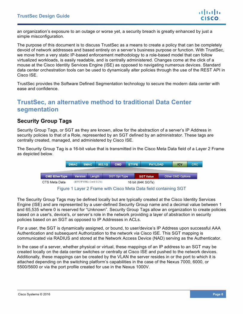
The Security Group Tag is a 16-bit value that is transmitted in the Cisco Meta Data field of a Layer 2 Frame as depicted below.
Figure 1 Layer 2 Frame with Cisco Meta Data field containing SGT
The Security Group Tags may be defined locally but are typically created at the Cisco Identity Services Engine (ISE) and are represented by a user-defined Security Group name and a decimal value between 1 and 65,535 where 0 is reserved for “Unknown”. Security Group Tags allow an organization to create policies based on a user's, device's, or server’s role in the network providing a layer of abstraction in security policies based on an SGT as opposed to IP Addresses in ACLs.
For a user, the SGT is dynamically assigned, or bound, to user/device’s IP Address upon successful AAA Authentication and subsequent Authorization to the network via Cisco ISE. This SGT mapping is communicated via RADIUS and stored at the Network Access Device (NAD) serving as the Authenticator.
In the case of a server, whether physical or virtual, these mappings of an IP address to an SGT may be created locally on the data center switches or centrally at Cisco ISE and pushed to the network devices. Additionally, these mappings can be created by the VLAN the server resides in or the port to which it is attached depending on the switching platform’s capabilities in the case of the Nexus 7000, 6000, or 5500/5600 or via the port profile created for use in the Nexus 1000V.
Cisco Systems © 2016 Page 7
TrustSec Design Guide
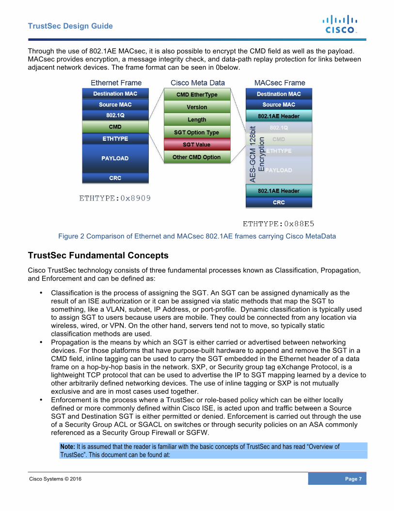
Through the use of 802.1AE MACsec, it is also possible to encrypt the CMD field as well as the payload. MACsec provides encryption, a message integrity check, and data-path replay protection for links between adjacent network devices. The frame format can be seen in 0below.
Figure 2 Comparison of Ethernet and MACsec 802.1AE frames carrying Cisco MetaData
TrustSec Fundamental Concepts Cisco TrustSec technology consists of three fundamental processes known as Classification, Propagation, and Enforcement and can be defined as:
• Classification is the process of assigning the SGT. An SGT can be assigned dynamically as the result of an ISE authorization or it can be assigned via static methods that map the SGT to something, like a VLAN, subnet, IP Address, or port-profile. Dynamic classification is typically used to assign SGT to users because users are mobile. They could be connected from any location via wireless, wired, or VPN. On the other hand, servers tend not to move, so typically static classification methods are used.
• Propagation is the means by which an SGT is either carried or advertised between networking devices. For those platforms that have purpose-built hardware to append and remove the SGT in a CMD field, inline tagging can be used to carry the SGT embedded in the Ethernet header of a data frame on a hop-by-hop basis in the network. SXP, or Security group tag eXchange Protocol, is a lightweight TCP protocol that can be used to advertise the IP to SGT mapping learned by a device to other arbitrarily defined networking devices. The use of inline tagging or SXP is not mutually exclusive and are in most cases used together.
• Enforcement is the process where a TrustSec or role-based policy which can be either locally defined or more commonly defined within Cisco ISE, is acted upon and traffic between a Source SGT and Destination SGT is either permitted or denied. Enforcement is carried out through the use of a Security Group ACL or SGACL on switches or through security policies on an ASA commonly referenced as a Security Group Firewall or SGFW.
Note: It is assumed that the reader is familiar with the basic concepts of TrustSec and has read “Overview of TrustSec”. This document can be found at:
Cisco Systems © 2016 Page 8
TrustSec Design Guide
http://www.cisco.com/c/dam/en/us/solutions/collateral/borderless-networks/trustsec/C07-730151-00_overview_of_trustSec_og.pdf
Also refer to the “Cisco TrustSec Quick Start Configuration Guide” at:
http://www.cisco.com/c/dam/en/us/solutions/collateral/enterprise-networks/trustsec/configuration-guide.pdf.
Benefits of Using TrustSec to Enforce a Security Policy Based on these Security Group Tags, role-based policies can be enforced on supporting hardware through the use of Security Group ACLs (SGACLs) on Cisco switching infrastructure, policies defined on Security Group Firewalls (SGFW) such as the ASA, an SGFW implemented on Cisco Routers, FirePOWER Threat Defense, on Cisco Web Security Appliances and products from other vendors. These policies may be as simple as a permit or deny or may include specific IP Port information in addition to source or destination SGT to identify specific applications or traffic.
It should be apparent, that when an abstraction of IP-based policies, such as that provided by the role-based policies provided by TrustSec and SGTs, access device and virtualized server mobility is greatly enhanced as an IP Address is no longer a consideration in enforcing policies in the network. Now, as an entity moves in the network either through mobile roaming in the case of access devices or server vMotion by virtue of the port profile when using the Nexus 1000V, one need not be concerned with having appropriate address-based ACLs defined on the destination device. The policy can follow them based on the SGT they have been assigned.
Through the use of TrustSec, organizations can:
• Identify servers, whether physical or virtual, by a “Role” rather than a static IP Address in a security policy.
• Use a Security Group Tag (SGT) to represent a role replacing an IP Address in a Security Policy. • Create policies that can be applied ubiquitously in Data Centers distributed geographically
throughout the World or located in the Cloud without the constraints and operational overhead IP Addressing imposes.
• Minimize the operational overhead from policy changes and the resulting outages that can occur due to configuration errors when changes are implemented based on server IP Addresses.
• Ensure that the policy stays current because as changes are made, legacy ACEs and configuration remnants aren’t left behind.
• Create easy to read policies that can be easily audited and changed as regulatory requirements demand.
• Provide Software Defined Segmentation as opposed to segmentation based on numerous VLANs or VRFs extending throughout the enterprise infrastructure.

Cisco Systems © 2016 Page 9
TrustSec Design Guide
Design Considerations
Data Center Architecture The data center architecture that will be used as an example in this document can be seen in 0below. In this diagram Nexus 7000s or 7700s are used providing Data Center Core and Aggregation switching. All links between the core and aggregation are configured as layer 3, routed links. The access layer in 0connects to the aggregation at layer 2 and can be configured for Fabricpath’s Spine/Leaf topology or common, classical Ethernet making use of spanning tree. In either scenario VPC/VPC+ is utilized between distribution and access as well as in the access layer itself for connection of the Nexus 1000V and the Nexus FEXs.
Note: For Cisco design guidance regarding Fabricpath and Virtual Port Channel (VPC) please refer to the following at
http://www.cisco.com/c/dam/en/us/products/collateral/switches/nexus-7000-series-switches/white_paper_c07-728188.pdf and
http://www.cisco.com/c/dam/en/us/td/docs/switches/datacenter/sw/design/vpc_design/vpc_best_practices_design_guide.pdf respectively.
Figure 3 Data Center Example
Cisco Systems © 2016 Page 10
TrustSec Design Guide
The access layer used as an example as depicted in Figure 3 consists of, but is certainly not limited, to three different models. On the far left are a pair of Nexus 5600s with two Nexus 22XX FEXs configured as Active-Active and implementing VPC+ between the FEX and Nexus 5600. In the center are two Nexus 5500s participating in a Fabricpath Domain with a combination of the Nexus 1000V, a vendor-specific vSwitch, and a bare metal server. Finally, on the far right are a pair of Fabric Interconnects connecting to a UCS-B series chassis.
Note: Although the Nexus 1000V is supported on VMware, Hyper-V, KVM, and Citrix XenServer, TrustSec is only supported for VMware at this time.
Note: For Cisco design guidance regarding Nexus 5000 switch and Nexus 2000 FEX with VPC please refer to
http://www.cisco.com/c/dam/en/us/products/collateral/switches/nexus-5000-series-switches/C07-572829-01_Design_N5K_N2K_vPC_DG.pdf.
For additional guidance regarding Fabricpath in an aggregation and access topology please refer to
http://www.cisco.com/c/en/us/products/collateral/switches/nexus-5000-series-switches/guide_c07-690079.html.
In addition to the switching components, an ASA cluster is connected at the data center aggregation layer providing a stateful transparent firewall to secure various security zones such as PCI, or electronic medical records (EMR).
Note: For ASA Clustering design guidance please refer to the following CVD entitled “Multi Data Center Sites Deployment of Cisco ASA Clustering with FirePOWER Services” at http://www.cisco.com/c/dam/m/en_us/solutions/data-center/offers/efficiency/dc-06_secure_data_center_design_guide_cte_en.pdf
The importance in showing each of these variations in deployment methodologies is to convey the flexibility of implementing TrustSec within the data center. The use of Security Group Tags for Software Defined Segmentation can be enabled in one pod, a security zone, or throughout the data center. The design should address each of the three fundamental concepts of a TrustSec design discussed earlier: classification, propagation, and enforcement.
Note: For information regarding platform-specific support of TrustSec features, please refer to the TrustSec Platform and capability matrix at http://www.cisco.com/c/en/us/solutions/enterprise-networks/trustsec/trustsec_matrix.html
Implementation considerations When implementing TrustSec in the data center, the initial focus should be in identifying the business needs that are met with segmentation, and identifying those assets that require protection. Often time, organizations feel the need to review the entire strategy to secure the data center and start by first trying to identify each and every asset, the applications they serve, and how servers should be assigned to roles. Typically this leads to numerous and often times unnecessary security groups and an extensive policy matrix that may require frequent revisions as the actual TrustSec implementation proceeds. A TrustSec implementation is easier if approached through small steps instead of a whole center redesign.
Instead of trying to address every requirement, often times the best approach is to simply identify an immediate requirement and/or application requiring segmentation. In limiting the initial scope of the project it will be easier to determine where all of the assets are located and how they attach to the network. Some examples of this may be segmenting PCI servers, servers containing patient medical records, customer financial data, and test or development environments.
Data Center Classification
Cisco Systems © 2016 Page 11
TrustSec Design Guide
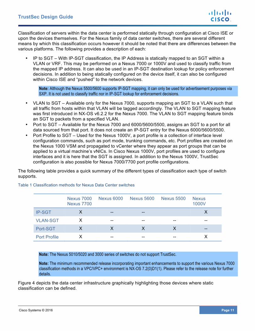
Classification of servers within the data center is performed statically through configuration at Cisco ISE or upon the devices themselves. For the Nexus family of data center switches, there are several different means by which this classification occurs however it should be noted that there are differences between the various platforms. The following provides a description of each:
• IP to SGT – With IP-SGT classification, the IP Address is statically mapped to an SGT within a VLAN or VRF. This may be performed on a Nexus 7000 or 1000V and used to classify traffic from the mapped IP address. It can also be used in an IP-SGT destination lookup for policy enforcement decisions. In addition to being statically configured on the device itself, it can also be configured within Cisco ISE and “pushed” to the network devices.
Note: Although the Nexus 5500/5600 supports IP-SGT mapping, it can only be used for advertisement purposes via SXP. It is not used to classify traffic nor in IP-SGT lookup for enforcement decisions.
• VLAN to SGT – Available only for the Nexus 7000, supports mapping an SGT to a VLAN such that all traffic from hosts within that VLAN will be tagged accordingly. The VLAN to SGT mapping feature was first introduced in NX-OS v6.2.2 for the Nexus 7000. The VLAN to SGT mapping feature binds an SGT to packets from a specified VLAN.
• Port to SGT – Available for the Nexus 7000 and 6000/5600/5500, assigns an SGT to a port for all data sourced from that port. It does not create an IP-SGT entry for the Nexus 6000/5600/5500.
• Port Profile to SGT – Used for the Nexus 1000V, a port profile is a collection of interface level configuration commands, such as port mode, trunking commands, etc. Port profiles are created on the Nexus 1000 VSM and propagated to vCenter where they appear as port groups that can be applied to a virtual machine’s vNICs. In Cisco Nexus 1000V, port profiles are used to configure interfaces and it is here that the SGT is assigned. In addition to the Nexus 1000V, TrustSec configuration is also possible for Nexus 7000/7700 port profile configurations.
The following table provides a quick summary of the different types of classification each type of switch supports.
Table 1 Classification methods for Nexus Data Center switches
Nexus 7000 Nexus 7700
Nexus 6000 Nexus 5600 Nexus 5500 Nexus 1000V
IP-SGT X -- -- X
VLAN-SGT X -- -- -- --
Port-SGT X X X X --
Port Profile X -- -- -- X
Note: The Nexus 5010/5020 and 3000 series of switches do not support TrustSec.
Note: The minimum recommended release incorporating important enhancements to support the various Nexus 7000 classification methods in a VPC/VPC+ environment is NX-OS 7.2(0)D1(1). Please refer to the release note for further details.
Figure 4 depicts the data center infrastructure graphically highlighting those devices where static classification can be defined.

Cisco Systems © 2016 Page 12
TrustSec Design Guide
Figure 4 Classification in the data center
Device SGT Classification
It is recommended that all network devices implementing TrustSec be classified as well as servers and access devices. This classification is called the “Device SGT”. This value can be assigned manually at the device itself or at Cisco ISE. All traffic sourced by any interface of the device will be tagged with this SGT. Any traffic such as management traffic, routing advertisements, etc, destined for an interface of the device will be inspected and any applicable TrustSec policy enforced. The Cisco ISE server has a default security group defined for the Device SGT named “TrustSec_Devices” and assigned SGT:02. It is recommended that all devices be assigned a common Device SGT.
Note: Always ensure that a policy exists to permit traffic between the Network Device SGT as source and destination if ever changing the ISE default policy to be covered in the Enforcement section. If the default is changed to deny traffic and a policy does not exist, all communications, most notably routing advertisements, will be dropped.
Classification via Port Profile on Nexus 7000 and Nexus 1000V
Starting with virtualized compute, virtual machines are individually tagged at the Nexus 1000V by virtue of the port profile assigned to the VM. As the virtual server is powered on, Device Tracking on the Nexus 1000V is used to learn the IP address of the VM through ARP messages and IP traffic.
The power of SGT assignment via port profile is that regardless of location in the data center, vMotion has no effect on the policy applicable to that VM as the port profile is consistent across ESXi hosts by virtue of the Nexus 1000V architecture. As a new workload spins up to augment an existing application, the new VM is automatically associated with the correct Security Group Tag.
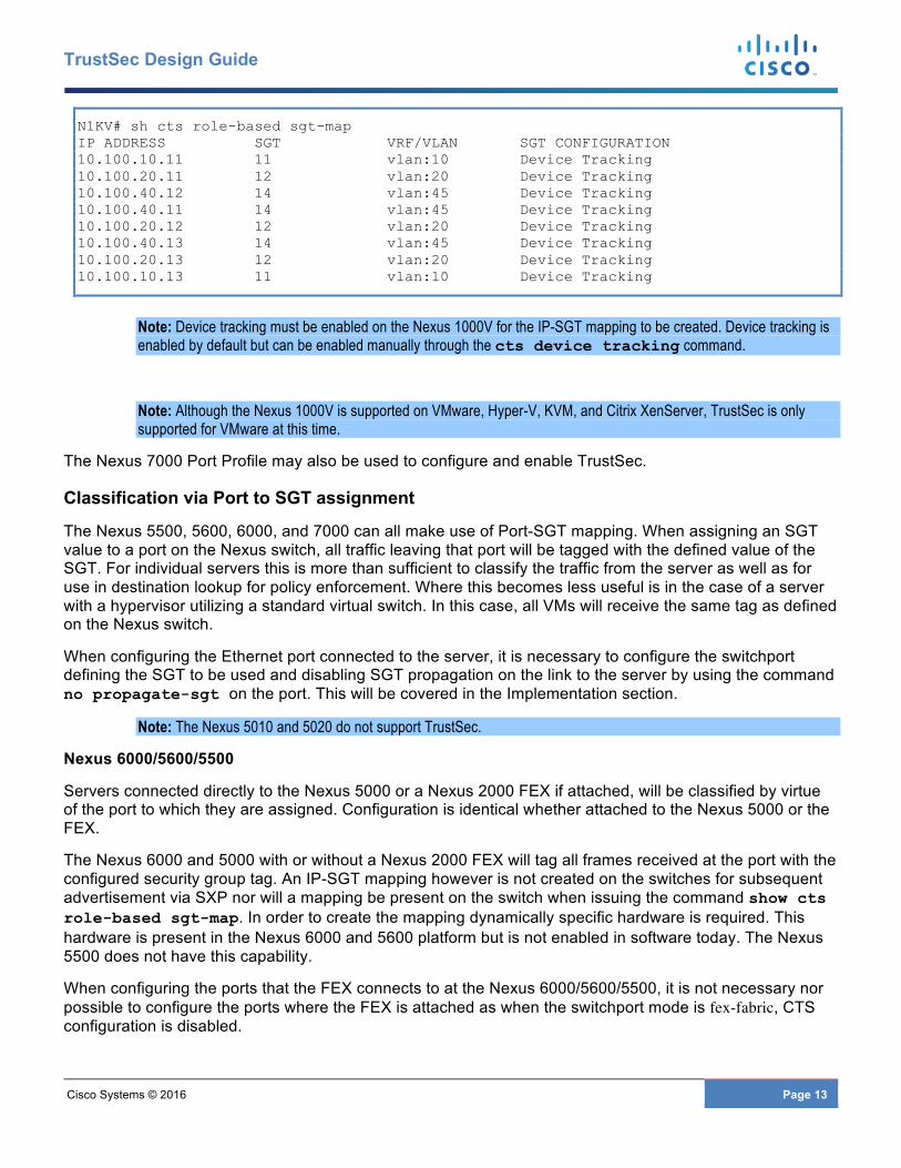
When port-profiles are used, a mapping will be created on the Nexus 1000V which can also be dynamically advertised via SXP as will be discussed later. This mapping can be seen below
Cisco Systems © 2016 Page 13
TrustSec Design Guide
N1KV# sh cts role-based sgt-map IP ADDRESS SGT VRF/VLAN SGT CONFIGURATION 10.100.10.11 11 vlan:10 Device Tracking 10.100.20.11 12 vlan:20 Device Tracking 10.100.40.12 14 vlan:45 Device Tracking 10.100.40.11 14 vlan:45 Device Tracking 10.100.20.12 12 vlan:20 Device Tracking 10.100.40.13 14 vlan:45 Device Tracking 10.100.20.13 12 vlan:20 Device Tracking 10.100.10.13 11 vlan:10 Device Tracking
Note: Device tracking must be enabled on the Nexus 1000V for the IP-SGT mapping to be created. Device tracking is enabled by default but can be enabled manually through the cts device tracking command.
Note: Although the Nexus 1000V is supported on VMware, Hyper-V, KVM, and Citrix XenServer, TrustSec is only supported for VMware at this time.
The Nexus 7000 Port Profile may also be used to configure and enable TrustSec.
Classification via Port to SGT assignment
The Nexus 5500, 5600, 6000, and 7000 can all make use of Port-SGT mapping. When assigning an SGT value to a port on the Nexus switch, all traffic leaving that port will be tagged with the defined value of the SGT. For individual servers this is more than sufficient to classify the traffic from the server as well as for use in destination lookup for policy enforcement. Where this becomes less useful is in the case of a server with a hypervisor utilizing a standard virtual switch. In this case, all VMs will receive the same tag as defined on the Nexus switch.
When configuring the Ethernet port connected to the server, it is necessary to configure the switchport defining the SGT to be used and disabling SGT propagation on the link to the server by using the command no propagate-sgt on the port. This will be covered in the Implementation section.
Note: The Nexus 5010 and 5020 do not support TrustSec.
Nexus 6000/5600/5500
Servers connected directly to the Nexus 5000 or a Nexus 2000 FEX if attached, will be classified by virtue of the port to which they are assigned. Configuration is identical whether attached to the Nexus 5000 or the FEX.
The Nexus 6000 and 5000 with or without a Nexus 2000 FEX will tag all frames received at the port with the configured security group tag. An IP-SGT mapping however is not created on the switches for subsequent advertisement via SXP nor will a mapping be present on the switch when issuing the command show cts role-based sgt-map. In order to create the mapping dynamically specific hardware is required. This hardware is present in the Nexus 6000 and 5600 platform but is not enabled in software today. The Nexus 5500 does not have this capability.
When configuring the ports that the FEX connects to at the Nexus 6000/5600/5500, it is not necessary nor possible to configure the ports where the FEX is attached as when the switchport mode is fex-fabric, CTS configuration is disabled.
Cisco Systems © 2016 Page 14
TrustSec Design Guide
When configuring the Nexus 2000 FEX, all interfaces must have cts manual and no propagate-sgt configured. It is not necessary to configure the FEX uplink ports to the parent switch with the policy static command.
When configuring the FEX it is recommended that the interfaces be configured using the port range rather than individual interfaces; i.e. e100/1/1-48. If configured one at a time, an error will be logged stating “Interface going error-disabled. CTS configuration should be consistent across all the interfaces with same FEX ID”. Likewise, when removing a command, use the port range again otherwise the port goes Error Disabled with an error stating “The destination group tag (DGT) value for the following type of traffic is 0 (unknown): Broadcast, Multicast, Unknown Unicast”.
Ensure that once the FEX ports have been enabled for TrustSec, that when returning to configure the SGT value, the value that is used exists within ISE otherwise an error will be logged stating “11304 Could not retrieve requested Security Group Tag”.
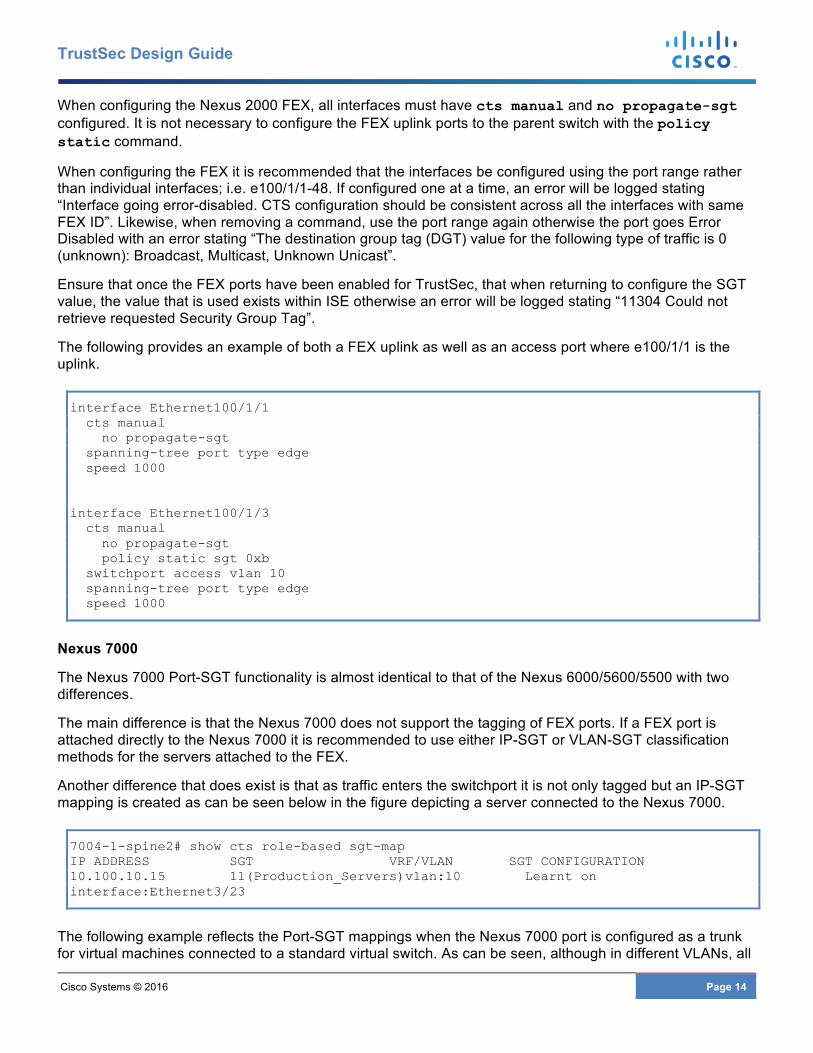
The following provides an example of both a FEX uplink as well as an access port where e100/1/1 is the uplink.
interface Ethernet100/1/1 cts manual no propagate-sgt spanning-tree port type edge speed 1000 interface Ethernet100/1/3 cts manual no propagate-sgt policy static sgt 0xb switchport access vlan 10 spanning-tree port type edge speed 1000
Nexus 7000
The Nexus 7000 Port-SGT functionality is almost identical to that of the Nexus 6000/5600/5500 with two differences.
The main difference is that the Nexus 7000 does not support the tagging of FEX ports. If a FEX port is attached directly to the Nexus 7000 it is recommended to use either IP-SGT or VLAN-SGT classification methods for the servers attached to the FEX.
Another difference that does exist is that as traffic enters the switchport it is not only tagged but an IP-SGT mapping is created as can be seen below in the figure depicting a server connected to the Nexus 7000.
7004-1-spine2# show cts role-based sgt-map IP ADDRESS SGT VRF/VLAN SGT CONFIGURATION 10.100.10.15 11(Production_Servers)vlan:10 Learnt on interface:Ethernet3/23
The following example reflects the Port-SGT mappings when the Nexus 7000 port is configured as a trunk for virtual machines connected to a standard virtual switch. As can be seen, although in different VLANs, all

Cisco Systems © 2016 Page 15
TrustSec Design Guide
receive the same security group tag of eleven. The obvious benefit of the creation of this mapping is that it can be advertised via SXP.
7004-1-agg1# show cts role-based sgt-map IP ADDRESS SGT VRF/VLAN SGT CONFIGURATION 10.100.15.14 11(Production_Servers)vlan:15 Learnt on interface:Ethernet3/32 10.100.25.14 11(Production_Servers)vlan:25 Learnt on interface:Ethernet3/32 10.1.100.11 11(Production_Servers)vlan:100 Learnt on interface:Ethernet3/32
The use of Port-SGT mapping on the Nexus 7000 is far less common than on the Nexus 6000 and 5600/5500. With the Nexus 6K/5K, Port-SGT mapping is the only method for classification at the time of this writing. The Nexus 7000 also supports VLAN-SGT and static IP-SGT definitions providing much greater flexibility for classifying servers. In NX-OS 7.3, the Nexus 7000 family will also support subnet-SGT mappings to provide greater flexibility.
Summary of port-level Classification
The following table summarizes port level based classifications across the Nexus product family.
Table 2 Port level classification
7000 6000 5600 5500 1000V Access Port X X X X X Trunk Port X X X X NA Supports tagging for FEX ports -- X X X NA Creates mapping on device X -- -- -- X Mapping can be advertised via SXP
X -- -- -- X
VLAN to SGT Classification and the Nexus 7000
In the Nexus family of switches, the Nexus 7000 is the only one that supports VLAN-SGT classification. As previously discussed, VLAN-SGT classification allows for SGT assignment based on the VLAN in which it resides. In order to classify via VLAN-SGT a switched virtual interface (SVI) must be created on the Nexus 7000 for it to create an IP to SGT binding for any active host on that VLAN. So for example, if a Nexus 7000 has a VLAN that provides no layer three gateway or routing functions, such as in the case of the inside VLAN of a transparent firewall, it is necessary to create an SVI with any unused IP address to be able to snoop ARP packets to discover the IP addresses of the servers in that VLAN. Using ARP Snooping the IP Address and MAC address are learned and based on the VLAN-SGT mapping, an IP-SGT mapping is created in the mapping database.
VLAN-SGT simplifies the migration from legacy to TrustSec-capable networks as follows:
• Supports devices that are not TrustSec-capable but are VLAN-capable.
Cisco Systems © 2016 Page 16
TrustSec Design Guide
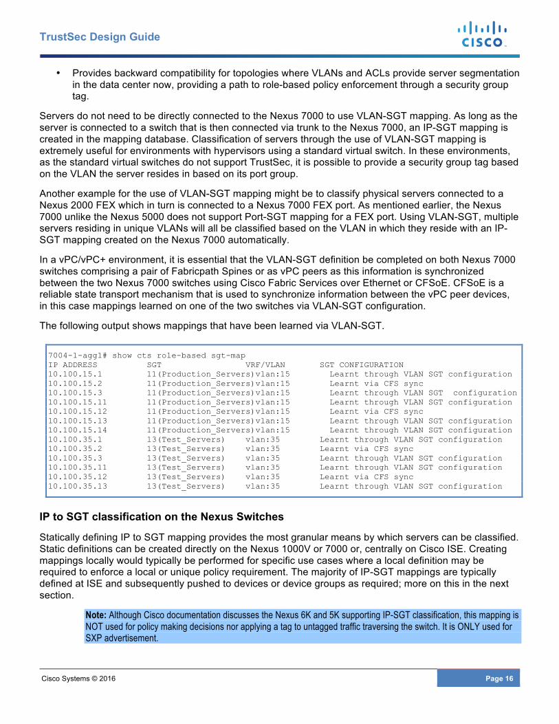
• Provides backward compatibility for topologies where VLANs and ACLs provide server segmentation in the data center now, providing a path to role-based policy enforcement through a security group tag.
Servers do not need to be directly connected to the Nexus 7000 to use VLAN-SGT mapping. As long as the server is connected to a switch that is then connected via trunk to the Nexus 7000, an IP-SGT mapping is created in the mapping database. Classification of servers through the use of VLAN-SGT mapping is extremely useful for environments with hypervisors using a standard virtual switch. In these environments, as the standard virtual switches do not support TrustSec, it is possible to provide a security group tag based on the VLAN the server resides in based on its port group.
Another example for the use of VLAN-SGT mapping might be to classify physical servers connected to a Nexus 2000 FEX which in turn is connected to a Nexus 7000 FEX port. As mentioned earlier, the Nexus 7000 unlike the Nexus 5000 does not support Port-SGT mapping for a FEX port. Using VLAN-SGT, multiple servers residing in unique VLANs will all be classified based on the VLAN in which they reside with an IP-SGT mapping created on the Nexus 7000 automatically.
In a vPC/vPC+ environment, it is essential that the VLAN-SGT definition be completed on both Nexus 7000 switches comprising a pair of Fabricpath Spines or as vPC peers as this information is synchronized between the two Nexus 7000 switches using Cisco Fabric Services over Ethernet or CFSoE. CFSoE is a reliable state transport mechanism that is used to synchronize information between the vPC peer devices, in this case mappings learned on one of the two switches via VLAN-SGT configuration.
The following output shows mappings that have been learned via VLAN-SGT.
7004-1-agg1# show cts role-based sgt-map IP ADDRESS SGT VRF/VLAN SGT CONFIGURATION 10.100.15.1 11(Production_Servers)vlan:15 Learnt through VLAN SGT configuration 10.100.15.2 11(Production_Servers)vlan:15 Learnt via CFS sync 10.100.15.3 11(Production_Servers)vlan:15 Learnt through VLAN SGT configuration 10.100.15.11 11(Production_Servers)vlan:15 Learnt through VLAN SGT configuration 10.100.15.12 11(Production_Servers)vlan:15 Learnt via CFS sync 10.100.15.13 11(Production_Servers)vlan:15 Learnt through VLAN SGT configuration 10.100.15.14 11(Production_Servers)vlan:15 Learnt through VLAN SGT configuration 10.100.35.1 13(Test_Servers) vlan:35 Learnt through VLAN SGT configuration 10.100.35.2 13(Test_Servers) vlan:35 Learnt via CFS sync 10.100.35.3 13(Test_Servers) vlan:35 Learnt through VLAN SGT configuration 10.100.35.11 13(Test_Servers) vlan:35 Learnt through VLAN SGT configuration 10.100.35.12 13(Test_Servers) vlan:35 Learnt via CFS sync 10.100.35.13 13(Test_Servers) vlan:35 Learnt through VLAN SGT configuration
IP to SGT classification on the Nexus Switches
Statically defining IP to SGT mapping provides the most granular means by which servers can be classified. Static definitions can be created directly on the Nexus 1000V or 7000 or, centrally on Cisco ISE. Creating mappings locally would typically be performed for specific use cases where a local definition may be required to enforce a local or unique policy requirement. The majority of IP-SGT mappings are typically defined at ISE and subsequently pushed to devices or device groups as required; more on this in the next section.
Note: Although Cisco documentation discusses the Nexus 6K and 5K supporting IP-SGT classification, this mapping is NOT used for policy making decisions nor applying a tag to untagged traffic traversing the switch. It is ONLY used for SXP advertisement.
Cisco Systems © 2016 Page 17
TrustSec Design Guide
Nexus 7000 and IP-SGT
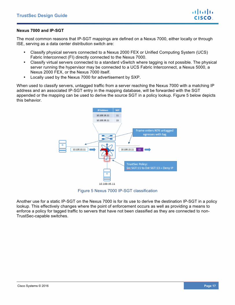
The most common reasons that IP-SGT mappings are defined on a Nexus 7000, either locally or through ISE, serving as a data center distribution switch are:
• Classify physical servers connected to a Nexus 2000 FEX or Unified Computing System (UCS) Fabric Interconnect (FI) directly connected to the Nexus 7000.
• Classify virtual servers connected to a standard vSwitch where tagging is not possible. The physical server running the hypervisor may be connected to a UCS Fabric Interconnect, a Nexus 5000, a Nexus 2000 FEX, or the Nexus 7000 itself.
• Locally used by the Nexus 7000 for advertisement by SXP.
When used to classify servers, untagged traffic from a server reaching the Nexus 7000 with a matching IP address and an associated IP-SGT entry in the mapping database, will be forwarded with the SGT appended or the mapping can be used to derive the source SGT in a policy lookup. Figure 5 below depicts this behavior.
Figure 5 Nexus 7000 IP-SGT classification
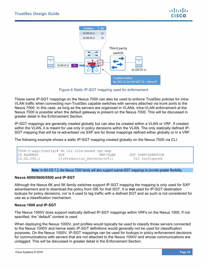
Another use for a static IP-SGT on the Nexus 7000 is for its use to derive the destination IP-SGT in a policy lookup. This effectively changes where the point of enforcement occurs as well as providing a means to enforce a policy for tagged traffic to servers that have not been classified as they are connected to non-TrustSec-capable switches.
Cisco Systems © 2016 Page 18
TrustSec Design Guide
Figure 6 Static IP-SGT mapping used for enforcement
These same IP-SGT mappings on the Nexus 7000 can also be used to enforce TrustSec policies for intra-VLAN traffic when connecting non-TrustSec capable switches with servers attached via trunk ports to the Nexus 7000. In this case, as long as the servers are organized in VLANs, intra-VLAN enforcement at the Nexus 7000 is possible when the default gateway is present on the Nexus 7000. This will be discussed in greater detail in the Enforcement Section.
IP-SGT mappings are generally created globally but can also be created within a VLAN or VRF. If created within the VLAN, it is meant for use only in policy decisions within the VLAN. The only statically defined IP-SGT mapping that will be re-advertised via SXP are for those mappings defined either globally or in a VRF.
The following example shows a static IP-SGT mapping created globally on the Nexus 7000 via CLI.
7004-1-agg1(config)# sh cts role-based sgt-map IP ADDRESS SGT VRF/VLAN SGT CONFIGURATION 10.20.200.1 11(Production_Servers)vrf:1 CLI Configured
Note: In NX-OS 7.3, the Nexus 7000 family will also support subnet-SGT mappings to provide greater flexibility.
Nexus 6000/5600/5500 and IP-SGT
Although the Nexus 6K and 5K family switches support IP-SGT mapping the mapping is only used for SXP advertisement and to download the policy from ISE for that SGT. It is not used for IP-SGT destination lookups for policy decisions, nor is it used to tag traffic with a defined SGT and as such is not considered for use as a classification mechanism.
Nexus 1000 and IP-SGT
The Nexus 1000V does support statically defined IP-SGT mappings within VRFs on the Nexus 1000. If not specified, the “default” context is used.
When deploying the Nexus 1000V, port profiles would typically be used to classify those servers connected to the Nexus 1000V and hence static IP-SGT definitions would generally not be used for classification purposes. On the Nexus 1000V, IP-SGT mappings can be used for lookups in policy enforcement decisions for communications with servers that are not attached to the Nexus 1000V and whose communications are untagged. This will be discussed in greater detail in the Enforcement Section.
Cisco Systems © 2016 Page 19
TrustSec Design Guide
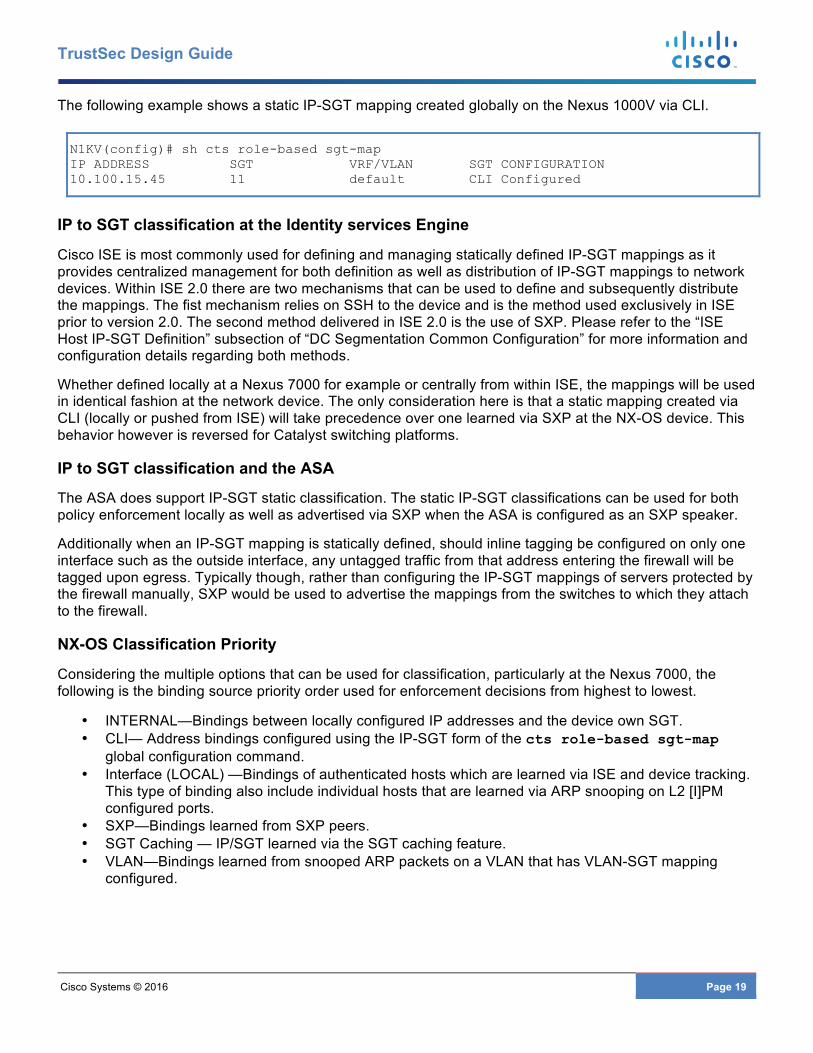
The following example shows a static IP-SGT mapping created globally on the Nexus 1000V via CLI.
N1KV(config)# sh cts role-based sgt-map IP ADDRESS SGT VRF/VLAN SGT CONFIGURATION 10.100.15.45 11 default CLI Configured
IP to SGT classification at the Identity services Engine
Cisco ISE is most commonly used for defining and managing statically defined IP-SGT mappings as it provides centralized management for both definition as well as distribution of IP-SGT mappings to network devices. Within ISE 2.0 there are two mechanisms that can be used to define and subsequently distribute the mappings. The fist mechanism relies on SSH to the device and is the method used exclusively in ISE prior to version 2.0. The second method delivered in ISE 2.0 is the use of SXP. Please refer to the “ISE Host IP-SGT Definition” subsection of “DC Segmentation Common Configuration” for more information and configuration details regarding both methods.
Whether defined locally at a Nexus 7000 for example or centrally from within ISE, the mappings will be used in identical fashion at the network device. The only consideration here is that a static mapping created via CLI (locally or pushed from ISE) will take precedence over one learned via SXP at the NX-OS device. This behavior however is reversed for Catalyst switching platforms.
IP to SGT classification and the ASA
The ASA does support IP-SGT static classification. The static IP-SGT classifications can be used for both policy enforcement locally as well as advertised via SXP when the ASA is configured as an SXP speaker.
Additionally when an IP-SGT mapping is statically defined, should inline tagging be configured on only one interface such as the outside interface, any untagged traffic from that address entering the firewall will be tagged upon egress. Typically though, rather than configuring the IP-SGT mappings of servers protected by the firewall manually, SXP would be used to advertise the mappings from the switches to which they attach to the firewall.
NX-OS Classification Priority
Considering the multiple options that can be used for classification, particularly at the Nexus 7000, the following is the binding source priority order used for enforcement decisions from highest to lowest.
• INTERNAL—Bindings between locally configured IP addresses and the device own SGT. • CLI— Address bindings configured using the IP-SGT form of the cts role-based sgt-map
global configuration command. • Interface (LOCAL) —Bindings of authenticated hosts which are learned via ISE and device tracking.
This type of binding also include individual hosts that are learned via ARP snooping on L2 [I]PM configured ports.
• SXP—Bindings learned from SXP peers. • SGT Caching — IP/SGT learned via the SGT caching feature. • VLAN—Bindings learned from snooped ARP packets on a VLAN that has VLAN-SGT mapping
configured.
Cisco Systems © 2016 Page 20
TrustSec Design Guide
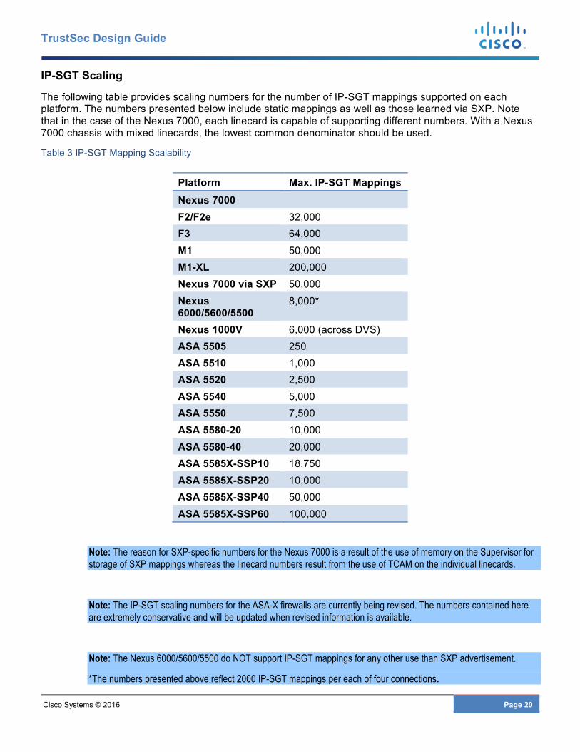
IP-SGT Scaling
The following table provides scaling numbers for the number of IP-SGT mappings supported on each platform. The numbers presented below include static mappings as well as those learned via SXP. Note that in the case of the Nexus 7000, each linecard is capable of supporting different numbers. With a Nexus 7000 chassis with mixed linecards, the lowest common denominator should be used.
Table 3 IP-SGT Mapping Scalability
Platform Max. IP-SGT Mappings Nexus 7000 F2/F2e 32,000 F3 64,000 M1 50,000 M1-XL 200,000 Nexus 7000 via SXP 50,000 Nexus 6000/5600/5500
8,000*
Nexus 1000V 6,000 (across DVS) ASA 5505 250 ASA 5510 1,000 ASA 5520 2,500 ASA 5540 5,000 ASA 5550 7,500 ASA 5580-20 10,000 ASA 5580-40 20,000 ASA 5585X-SSP10 18,750 ASA 5585X-SSP20 10,000 ASA 5585X-SSP40 50,000 ASA 5585X-SSP60 100,000
Note: The reason for SXP-specific numbers for the Nexus 7000 is a result of the use of memory on the Supervisor for storage of SXP mappings whereas the linecard numbers result from the use of TCAM on the individual linecards.
Note: The IP-SGT scaling numbers for the ASA-X firewalls are currently being revised. The numbers contained here are extremely conservative and will be updated when revised information is available.
Note: The Nexus 6000/5600/5500 do NOT support IP-SGT mappings for any other use than SXP advertisement.
*The numbers presented above reflect 2000 IP-SGT mappings per each of four connections.
Cisco Systems © 2016 Page 21
TrustSec Design Guide
Data Center Security Group Tag Propagation SGT propagation within the data center will typically be a combination of both Security Group Tag Exchange Protocol (SXP) and inline tagging especially when a firewall is in use to protect a particular pod or security zone. Normally the rule of thumb should be to enable inline tagging wherever possible in those areas of the data center where Nexus switching products will be used to enforce policy via Security Group ACLs (SGACL). In instances where an ASA is deployed, SXP will minimally be used for the inside interface with the optional use of inline tagging to the outside interface; more on this to follow.
Inline Tagging in the Data Center
There are two methods of configuring the infrastructure to support TrustSec inline tagging on Ethernet links and sometimes referred to as enabling CTS (Cisco Trusted Security) on the link:
• Inline tagging using 802.1X for link authentication • Inline tagging configured in Manual Mode without link authentication
Inline tagging configured to require link authentication through the cts dot1x command requires each side of the link to exchange credentials obtained during network device authentication at ISE known as Network Domain Admission Control (NDAC).
Inline tagging configured without requirement for link authentication through the cts manual command will simply exchange messages relative to CTS enablement and will bring the link up without any authentication and exchange of credentials.
It is recommended to only configure inline tagging on the Nexus data center switches using the manual mode. With the “dot1x” mode, links once they have been brought up, will periodically require re-authentication with Cisco ISE. If the communications to ISE is disrupted the link will be brought down until such time that communications are re-established. To prevent this, a feature known as “Critical AUTH” has been developed but has yet to be implemented on the Nexus family of switches. With Critical AUTH, the authentication credentials are cached and used until such time that communications to ISE have been re-established. Without Critical AUTH support, it is recommended to configure the links for manual mode only.
Note: Based on the recommended use of Manual Mode when configuring Nexus Ethernet links, “dot1x Mode” will not be covered in this document. Please refer to Cisco documentation for further details.
Common to both of these methods is the ability to employ MACsec (802.1ae) which provides encryption, a message integrity check, and data-path replay protection for links between adjacent network devices. MACsec therefore protects the CMD field and the SGT value it contains while also encrypting the payload.
Note: MACsec requires specific hardware for the wirespeed encryption it supports which is only found on certain Nexus 7000 linecards. The ASA and Nexus 6000/5600/5500 switches do not support MACsec. MACsec will not be discussed in this document. Please refer to Cisco documentation for further details.
Nexus Data Center Switches and ASA with Inline Tagging
Within the data center switching infrastructure, inline tagging should always be implemented and utilized as much as possible for SGT propagation With inline tagging supported across the Nexus 7K, 6K, 5K, and 1KV switching there are few implementation challenges from an equipment perspective.
Note: When enabling TrustSec on an interface through the use of the cts manual command and subsequently entering the policy static command, it is imperative that the cts manual config mode be exited through the use of the exit command. The interface must then be shut down and brought back up to enable CTS. Both sides of the link must be
Cisco Systems © 2016 Page 22
TrustSec Design Guide
configured for CTS. If only one side of the link is configured, the links will show that they are up however traffic will not pass.
Note: The Nexus 5600 and 5500 supports Port-SGT assignment for Nexus 2000 FEX ports. The Nexus 7000 however does not. When connecting a FEX to the Nexus 7000, static IP-SGT mappings must be created on the Nexus 7000 for those servers attached to the FEX.
While SXP provides an alternate means of propagating tags within the data center, one of the main reasons to use inline tagging concerns scalability relative to the resources available at the various platforms for supporting SXP IP-SGT mappings. The SXP scaling numbers are provided in the following section on SXP in the data center. Alternatively though, there are scenarios where SXP is best suited and perhaps the only solution for SGT propagation in the data center. This will also be discussed.
In addition to Nexus switching products, the ASA is commonly deployed in the data center and typically connected at the data center distribution layer to protect minimally a subset of applications along with the associated data. With software version 9.3.1 the ASA firewalls now support inline tagging on Ethernet interfaces. Typically though, SXP will still be used to advertise the IP-SGT mappings to the firewall for those servers protected in a secured pod. This will be discussed in greater detail in the following section on common scenarios for SXP usage in the data center.
Note: The ASA 5510, 5520, 5540, 5550, and the 5580 do not support SGT over Ethernet, only SXP.
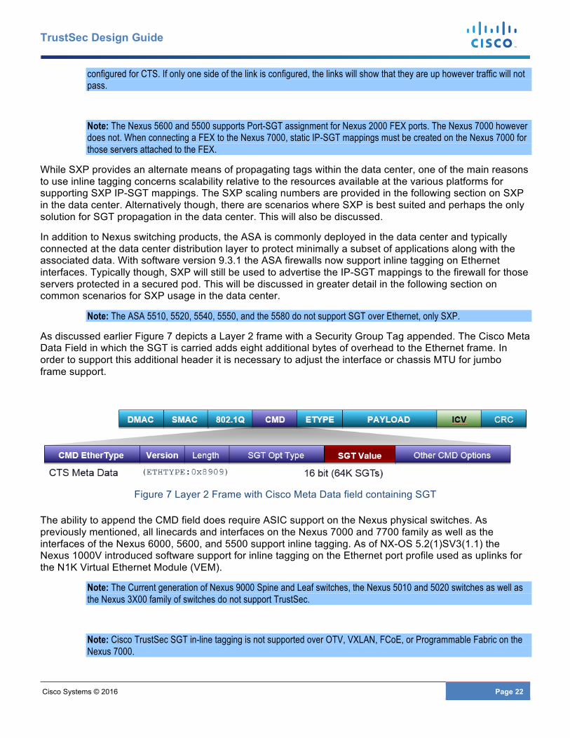
As discussed earlier Figure 7 depicts a Layer 2 frame with a Security Group Tag appended. The Cisco Meta Data Field in which the SGT is carried adds eight additional bytes of overhead to the Ethernet frame. In order to support this additional header it is necessary to adjust the interface or chassis MTU for jumbo frame support.
Figure 7 Layer 2 Frame with Cisco Meta Data field containing SGT
The ability to append the CMD field does require ASIC support on the Nexus physical switches. As previously mentioned, all linecards and interfaces on the Nexus 7000 and 7700 family as well as the interfaces of the Nexus 6000, 5600, and 5500 support inline tagging. As of NX-OS 5.2(1)SV3(1.1) the Nexus 1000V introduced software support for inline tagging on the Ethernet port profile used as uplinks for the N1K Virtual Ethernet Module (VEM).
Note: The Current generation of Nexus 9000 Spine and Leaf switches, the Nexus 5010 and 5020 switches as well as the Nexus 3X00 family of switches do not support TrustSec.
Note: Cisco TrustSec SGT in-line tagging is not supported over OTV, VXLAN, FCoE, or Programmable Fabric on the Nexus 7000.
Cisco Systems © 2016 Page 23
TrustSec Design Guide
Note: For information regarding platform-specific support of TrustSec features, please refer to the TrustSec Platform and capability matrix at http://www.cisco.com/c/en/us/solutions/enterprise-networks/trustsec/trustsec_matrix.html
The following subsections document any platform-specific considerations relative to inline tagging support.
Port Channels and CTS (Inline Tagging)
Cisco TrustSec interface configurations (CTS) on port channel members must be exactly the same. If a port channel member is inconsistent with the other port channel members, it will be error disabled. In order to enable CTS, each member must be removed from the port channel before enabling cts through the cts manual command. An error will occur if an attempt is made to add a CTS-enabled link to an existing port channel. It is not necessary to configure CTS on the port channel interface itself as the determination of whether a peer is trusted or not and its capability to propagate SGTs on egress are made at the physical interface level.
Nexus 7000 F3 Linecard
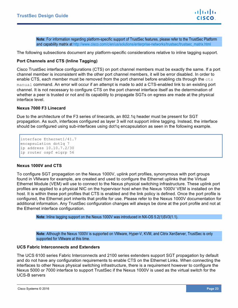
Due to the architecture of the F3 series of linecards, an 802.1q header must be present for SGT propagation. As such, interfaces configured as layer 3 will not support inline tagging. Instead, the interface should be configured using sub-interfaces using dot1q encapsulation as seen in the following example.
interface Ethernet1/41.7 encapsulation dot1q 7 ip address 10.10.7.2/30 ip router ospf eigrp 56
Nexus 1000V and CTS
To configure SGT propagation on the Nexus 1000V, uplink port profiles, synonymous with port groups found in VMware for example, are created and used to configure the Ethernet uplinks that the Virtual Ethernet Module (VEM) will use to connect to the Nexus physical switching infrastructure. These uplink port profiles are applied to a physical NIC on the hypervisor host when the Nexus 1000V VEM is installed on the host. It is within these port profiles that CTS is enabled and the link policy is defined. Once the port profile is configured, the Ethernet port inherits that profile for use. Please refer to the Nexus 1000V documentation for additional information. Any TrustSec configuration changes will always be done at the port profile and not at the Ethernet interface configuration.
Note: Inline tagging support on the Nexus 1000V was introduced in NX-OS 5.2(1)SV3(1.1).
Note: Although the Nexus 1000V is supported on VMware, Hyper-V, KVM, and Citrix XenServer, TrustSec is only supported for VMware at this time.
UCS Fabric Interconnects and Extenders
The UCS 6100 series Fabric Interconnects and 2100 series extenders support SGT propagation by default and do not have any configuration requirements to enable CTS on the Ethernet Links. When connecting the interfaces to other Nexus physical switching infrastructure, there is a requirement however to configure the Nexus 5000 or 7000 interface to support TrustSec if the Nexus 1000V is used as the virtual switch for the UCS-B servers

Cisco Systems © 2016 Page 24
TrustSec Design Guide
Note: It is recommended that that the Fabric Interconnects be running at version 2.2.3c or later. Issues have been found with some earlier releases.
ASA inline tagging considerations
Configuration for the ASA to support inline tagging was introduced in 9.3.1 for the ASA 5505, 5512, 5515, 5525, 5545, 5555, and 5585 and the “X” series and can be implemented regardless of:
• Firewall mode, Transparent or Routed • Multi-context • Dedicated interfaces or trunks are used for connectivity • HA method
When configuring inline tagging on dedicated interfaces of the ASA, it is possible to configure any or all of the individual interfaces, the outside interface as an example, to support inline tagging. The typical use case for inline tagging to the outside interface is when SXP is used to advertise server IP-SGT mappings to the firewall for policy enforcement as seen in Figure 8 below.
Figure 8 Inline tagging used with SXP
With inline tagging configured on both interfaces, SGFW policy enforcement is only possible when the IP-SGT mappings of the protected servers have either been advertised via SXP to the firewall or statically defined on the firewall as there is no mechanism to “learn” the mappings of transit traffic. Without the IP-SGT mappings, an ASA Firewall can still perform critical packet inspection and redirection to FirePOWER services for Next-Gen IPS, and Advanced Malware Protection but the switching infrastructure must have the appropriate SGACL policies downloaded as well to permit or deny traffic to the servers.
When the ASA is configured with a trunk supporting sub-interfaces for both the inside and outside interfaces, regardless of Routed or Transparent Mode, both sub-interfaces will be configured to support
Cisco Systems © 2016 Page 25
TrustSec Design Guide
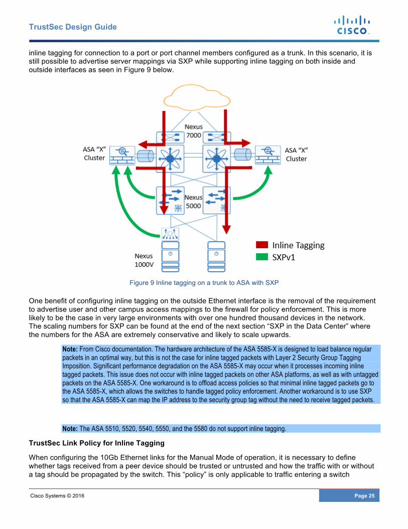
inline tagging for connection to a port or port channel members configured as a trunk. In this scenario, it is still possible to advertise server mappings via SXP while supporting inline tagging on both inside and outside interfaces as seen in Figure 9 below.
Figure 9 Inline tagging on a trunk to ASA with SXP
One benefit of configuring inline tagging on the outside Ethernet interface is the removal of the requirement to advertise user and other campus access mappings to the firewall for policy enforcement. This is more likely to be the case in very large environments with over one hundred thousand devices in the network. The scaling numbers for SXP can be found at the end of the next section “SXP in the Data Center” where the numbers for the ASA are extremely conservative and likely to scale upwards.
Note: From Cisco documentation. The hardware architecture of the ASA 5585-X is designed to load balance regular packets in an optimal way, but this is not the case for inline tagged packets with Layer 2 Security Group Tagging Imposition. Significant performance degradation on the ASA 5585-X may occur when it processes incoming inline tagged packets. This issue does not occur with inline tagged packets on other ASA platforms, as well as with untagged packets on the ASA 5585-X. One workaround is to offload access policies so that minimal inline tagged packets go to the ASA 5585-X, which allows the switches to handle tagged policy enforcement. Another workaround is to use SXP so that the ASA 5585-X can map the IP address to the security group tag without the need to receive tagged packets.
Note: The ASA 5510, 5520, 5540, 5550, and the 5580 do not support inline tagging.
TrustSec Link Policy for Inline Tagging
When configuring the 10Gb Ethernet links for the Manual Mode of operation, it is necessary to define whether tags received from a peer device should be trusted or untrusted and how the traffic with or without a tag should be propagated by the switch. This “policy” is only applicable to traffic entering a switch
Cisco Systems © 2016 Page 26
TrustSec Design Guide
interface and not upon egress from the switch. When the interface is configured for the trusted state, the tag encapsulated in the frame will be propagated as is. For those frames arriving at an interface that have either an empty SGT value in the CMD field or 00 (the “unknown” tag) or no CMD field at all, the behavior will vary depending on platform and is discussed later in this section. In the case of having defined the peer as “untrusted”, the tag present, whether a defined value, unknown, or if CMD is missing altogether, will be overwritten by the SGT value specified in the policy command. This is accomplished through the use of the policy static command on a switch interface.
The first example enables TrustSec on the interface through the cts manual command and creates a policy to trust the tag embedded in a frame from its peer through the trusted keyword. This results in forwarding or processing the frame using the embedded SGT.
(config-if)#cts manual (config-if-cts-manual)# policy static sgt id trusted
Alternatively if the tags embedded in frames for a peer should not be trusted and overwritten, the policy static command is issued without the trusted keyword and the SGT will be overwritten by the value (ID) specified in the command.
(config-if)#cts manual (config-if-cts-manual)# policy static sgt id
The policy definition is required for both the Catalyst and the Nexus family of switches however the behavior in how frames are processed and the tag used is different. Although this document is focused specifically on Nexus data center switches, it is important to understand these differences while implementing TrustSec. This will come into play particularly during migrations where only a small subset of servers or access devices are tagged with all other traffic being untagged.
Within this document, the data center infrastructure will make use of all “trusted” interfaces. There are instances however where a data center has a requirement for strict policy control, such as at the edge of the TrustSec domain. Here it may be necessary to mark traffic for specific treatment by applying a specific SGT and hence the use of the “untrusted” policy state. The following diagram and description provides an example of the behavior of the policy static command when a peer is untrusted. This behavior is identical whether used on a Catalyst 6500 or Nexus 7000 interface and is shown in Figure 10 below.
Reference to SGT:00 and “untagged” traffic will be found throughout this section. When referring to SGT:00 it should be considered as analogous to “Unknown” traffic which is a frame with a CMD but no value in the SGT Value. Untagged traffic however has no Cisco Meta Data (CMD) field in the Ethernet header.
Cisco Systems © 2016 Page 27
TrustSec Design Guide
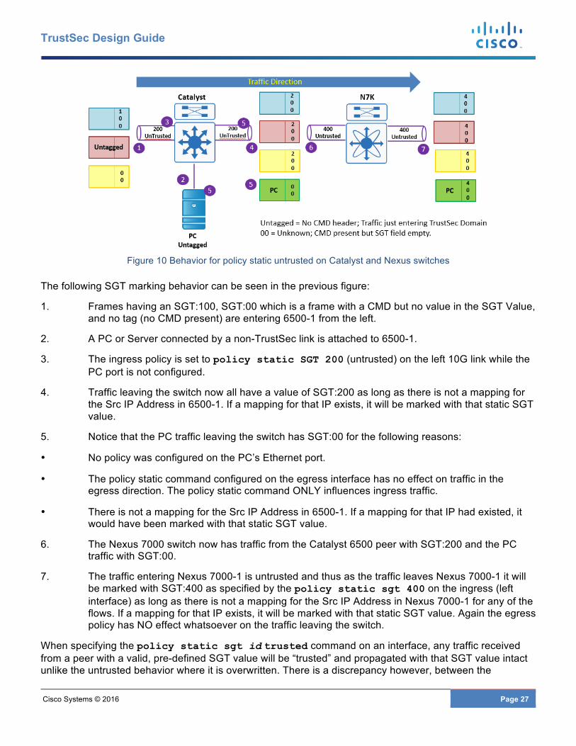
Figure 10 Behavior for policy static untrusted on Catalyst and Nexus switches
The following SGT marking behavior can be seen in the previous figure:
1. Frames having an SGT:100, SGT:00 which is a frame with a CMD but no value in the SGT Value, and no tag (no CMD present) are entering 6500-1 from the left.
2. A PC or Server connected by a non-TrustSec link is attached to 6500-1.
3. The ingress policy is set to policy static SGT 200 (untrusted) on the left 10G link while the PC port is not configured.
4. Traffic leaving the switch now all have a value of SGT:200 as long as there is not a mapping for the Src IP Address in 6500-1. If a mapping for that IP exists, it will be marked with that static SGT value.
5. Notice that the PC traffic leaving the switch has SGT:00 for the following reasons:
• No policy was configured on the PC’s Ethernet port.
• The policy static command configured on the egress interface has no effect on traffic in the egress direction. The policy static command ONLY influences ingress traffic.
• There is not a mapping for the Src IP Address in 6500-1. If a mapping for that IP had existed, it would have been marked with that static SGT value.
6. The Nexus 7000 switch now has traffic from the Catalyst 6500 peer with SGT:200 and the PC traffic with SGT:00.
7. The traffic entering Nexus 7000-1 is untrusted and thus as the traffic leaves Nexus 7000-1 it will be marked with SGT:400 as specified by the policy static sgt 400 on the ingress (left interface) as long as there is not a mapping for the Src IP Address in Nexus 7000-1 for any of the flows. If a mapping for that IP exists, it will be marked with that static SGT value. Again the egress policy has NO effect whatsoever on the traffic leaving the switch.
When specifying the policy static sgt id trusted command on an interface, any traffic received from a peer with a valid, pre-defined SGT value will be “trusted” and propagated with that SGT value intact unlike the untrusted behavior where it is overwritten. There is a discrepancy however, between the
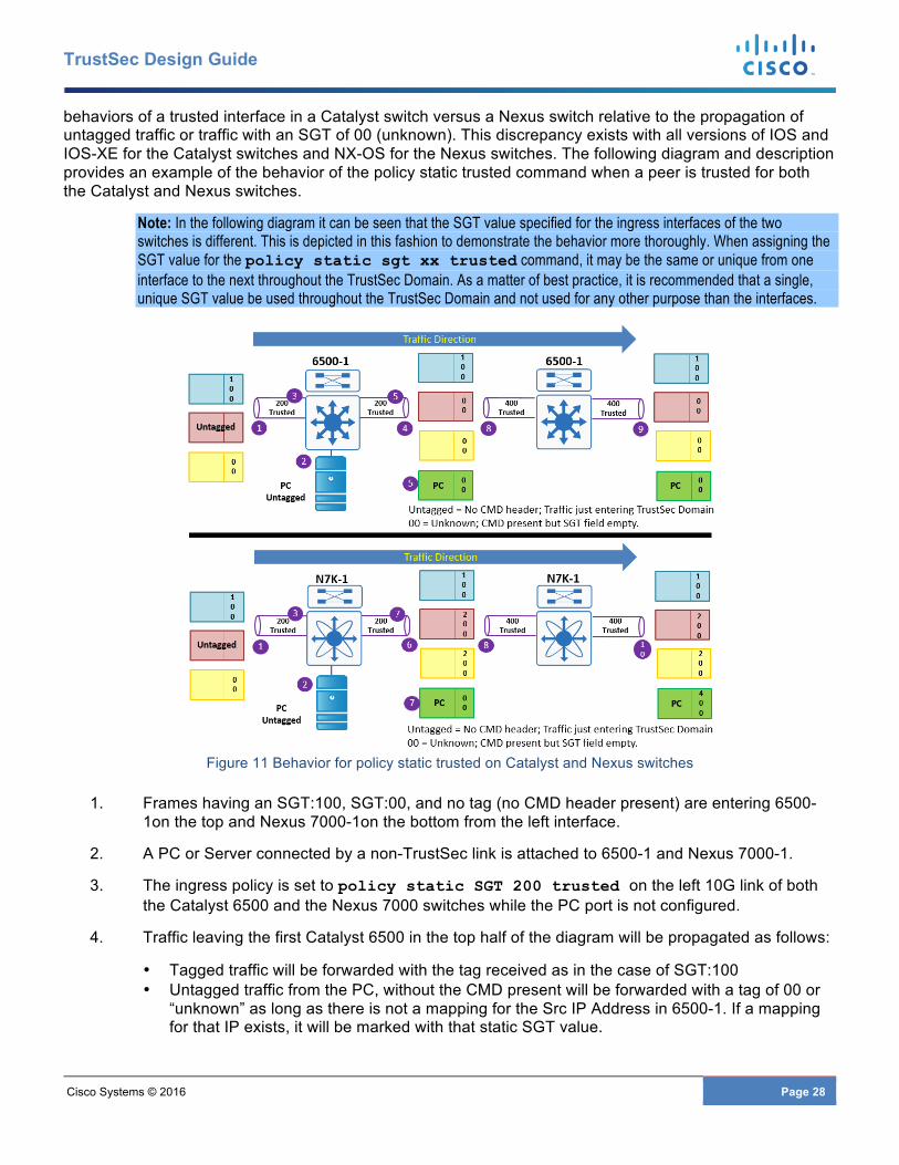
Cisco Systems © 2016 Page 28
TrustSec Design Guide
behaviors of a trusted interface in a Catalyst switch versus a Nexus switch relative to the propagation of untagged traffic or traffic with an SGT of 00 (unknown). This discrepancy exists with all versions of IOS and IOS-XE for the Catalyst switches and NX-OS for the Nexus switches. The following diagram and description provides an example of the behavior of the policy static trusted command when a peer is trusted for both the Catalyst and Nexus switches.
Note: In the following diagram it can be seen that the SGT value specified for the ingress interfaces of the two switches is different. This is depicted in this fashion to demonstrate the behavior more thoroughly. When assigning the SGT value for the policy static sgt xx trusted command, it may be the same or unique from one interface to the next throughout the TrustSec Domain. As a matter of best practice, it is recommended that a single, unique SGT value be used throughout the TrustSec Domain and not used for any other purpose than the interfaces.
Figure 11 Behavior for policy static trusted on Catalyst and Nexus switches
1. Frames having an SGT:100, SGT:00, and no tag (no CMD header present) are entering 6500-1on the top and Nexus 7000-1on the bottom from the left interface.
2. A PC or Server connected by a non-TrustSec link is attached to 6500-1 and Nexus 7000-1.
3. The ingress policy is set to policy static SGT 200 trusted on the left 10G link of both the Catalyst 6500 and the Nexus 7000 switches while the PC port is not configured.
4. Traffic leaving the first Catalyst 6500 in the top half of the diagram will be propagated as follows:
• Tagged traffic will be forwarded with the tag received as in the case of SGT:100 • Untagged traffic from the PC, without the CMD present will be forwarded with a tag of 00 or
“unknown” as long as there is not a mapping for the Src IP Address in 6500-1. If a mapping for that IP exists, it will be marked with that static SGT value.
Cisco Systems © 2016 Page 29
TrustSec Design Guide
• Unknown traffic, SGT:00, will be forwarded with 00 as long as there is not a mapping for the Src IP Address in 6500-1. If a mapping for that IP exists, it will be marked with that static SGT value.
5. Notice that the PC traffic leaving the Catalyst 6500 has SGT:00 for the following reasons:
• No policy was configured on the PC’s Ethernet port. • The policy static command configured on an egress interface has no effect on traffic in the
egress direction. The policy static command ONLY influence ingress traffic. • There was not a mapping for the Src IP Address in 6500-1. If a mapping for that IP existed,
the traffic would have been marked with that static SGT value.
6. Traffic leaving the first Nexus 7000 switch in the bottom half of the diagram will be propagated as follows:
• Tagged traffic will be forwarded with the tag received as in the case of SGT:100 • Untagged traffic from the PC, without the CMD present will be forwarded with a tag of 00 as
long as there is not a mapping for the Src IP Address in Nexus 7000-1. If a mapping for that IP exists, it will be marked with that static SGT value.
• Unknown traffic SGT:00, will be forwarded and re-marked with 200 as long as there is not a mapping for the Src IP Address in Nexus 7000-1. If a mapping for that IP exists, it will be marked with that static SGT value.
7. Notice that the PC traffic leaving the Nexus 7000 has SGT:00 for the following reasons:
• No policy was configured on the PC’s Ethernet port. • The policy static command configured on an egress interface has no effect on traffic in the
egress direction. The policy static command only influences ingress traffic. • There was not a mapping for the Src IP Address in Nexus 7000-1. If a mapping for that IP
existed, the traffic would have been marked with that static SGT value.
8. The second Catalyst 6500 and Nexus 7000 switches are configured with policy static sgt 400 trusted on their ingress interfaces.
9. Traffic leaving the second Catalyst 6500 in the top half of the diagram will be propagated as follows:
• Tagged traffic will be forwarded with the tag received as in the case of SGT:100 • Unknown traffic, SGT:00, will be forwarded with 00 as long as there is not a mapping for the
Src IP Address in 6500-1. If a mapping for that IP exists, the traffic will be marked with that static SGT value.
10. Traffic leaving the second Nexus 7000 switch in the bottom half of the diagram will be propagated as follows:
• Tagged traffic will be forwarded with the tag received as in the case of SGT:100 and SGT:200
• Unknown traffic, SGT:00, will be forwarded and re-marked with 400 as long as there is not a mapping for the Src IP Address in Nexus 7000-1. If a mapping for that IP exists, it will be marked with that static SGT value.
11. In the diagram above remember that the egress policy has NO effect whatsoever on the traffic leaving either the Catalyst 6500 or Nexus 7000.
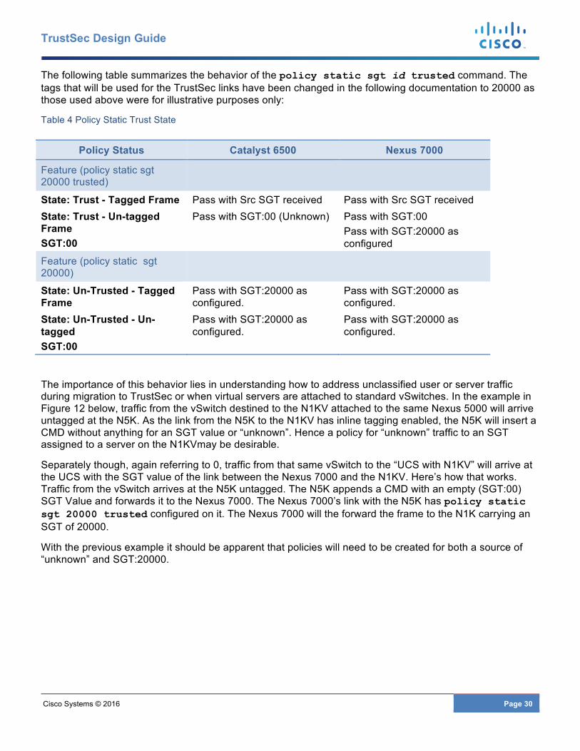
Cisco Systems © 2016 Page 30
TrustSec Design Guide
The following table summarizes the behavior of the policy static sgt id trusted command. The tags that will be used for the TrustSec links have been changed in the following documentation to 20000 as those used above were for illustrative purposes only:
Table 4 Policy Static Trust State
Policy Status Catalyst 6500 Nexus 7000
Feature (policy static sgt 20000 trusted)
State: Trust - Tagged Frame Pass with Src SGT received Pass with Src SGT received State: Trust - Un-tagged Frame SGT:00
Pass with SGT:00 (Unknown) Pass with SGT:00 Pass with SGT:20000 as configured
Feature (policy static sgt 20000)
State: Un-Trusted - Tagged Frame
Pass with SGT:20000 as configured.
Pass with SGT:20000 as configured.
State: Un-Trusted - Un-tagged SGT:00
Pass with SGT:20000 as configured.
Pass with SGT:20000 as configured.
The importance of this behavior lies in understanding how to address unclassified user or server traffic during migration to TrustSec or when virtual servers are attached to standard vSwitches. In the example in Figure 12 below, traffic from the vSwitch destined to the N1KV attached to the same Nexus 5000 will arrive untagged at the N5K. As the link from the N5K to the N1KV has inline tagging enabled, the N5K will insert a CMD without anything for an SGT value or “unknown”. Hence a policy for “unknown” traffic to an SGT assigned to a server on the N1KVmay be desirable.
Separately though, again referring to 0, traffic from that same vSwitch to the “UCS with N1KV” will arrive at the UCS with the SGT value of the link between the Nexus 7000 and the N1KV. Here’s how that works. Traffic from the vSwitch arrives at the N5K untagged. The N5K appends a CMD with an empty (SGT:00) SGT Value and forwards it to the Nexus 7000. The Nexus 7000’s link with the N5K has policy static sgt 20000 trusted configured on it. The Nexus 7000 will the forward the frame to the N1K carrying an SGT of 20000.
With the previous example it should be apparent that policies will need to be created for both a source of “unknown” and SGT:20000.

Cisco Systems © 2016 Page 31
TrustSec Design Guide
Figure 12 Link behavior with untagged traffic
The recommendation established in this guide is to configure all interfaces within the TrustSec Domain as trusted. It is also strongly advised that the SGT value used in the policy static command is a unique value dedicated to interfaces only, and more specifically, not the Device SGT. This will allow for the creation of policies for enforcement of traffic being remarked with the link tag as it had not been previously classified while allowing a unique device SGT for enforcing access to the networking infrastructure.
SXP in the Data Center
SXP can be used both inside and outside of the data center to propagate IP-SGT mappings that have been created as a result of classification at Nexus Data Center switches and has two modes of operation; listener mode where the device listens for advertisements and speaker mode where the device advertises mappings.
Generally, when used inside of the data center, SXP is used primarily for either advertising server’s IP-SGT mappings from the Nexus switches to an ASA implemented as a Security Group Firewall (SGFW) or to advertise IP-SGT mappings for servers connected to infrastructure that does not support TrustSec. When used with the ASA it is customary to advertise the IP-SGT mappings of servers located behind the firewall for use in policy enforcement. When used to advertise IP-SGT mappings of servers connected to standard hypervisor vSwitches or switches that don’t support TrustSec, a connection could be built from ISE or other SXP speaker, such as an ASR router, to a Nexus 7000 or 1000V to be used for either policy enforcement at the switch or in the case of the Nexus 7000, classification of traffic traversing the switch. Other uses may include advertisement to Cloud infrastructure or across transport which may be unable to support inline tagging.
SXP has been supported for a number of years and over time has been revised to include additional capabilities with SXPv4 being the latest. Nexus data center switches at the time of this writing all support SXP v1 while the ASA SGFW supports SXP v2; Version 3 support for both the Nexus 7000 and the ASA will be coming in the first half of 2016. In order to better understand SXP versions the table below provides a quick summary of the various versions and the unique functionality found in each.
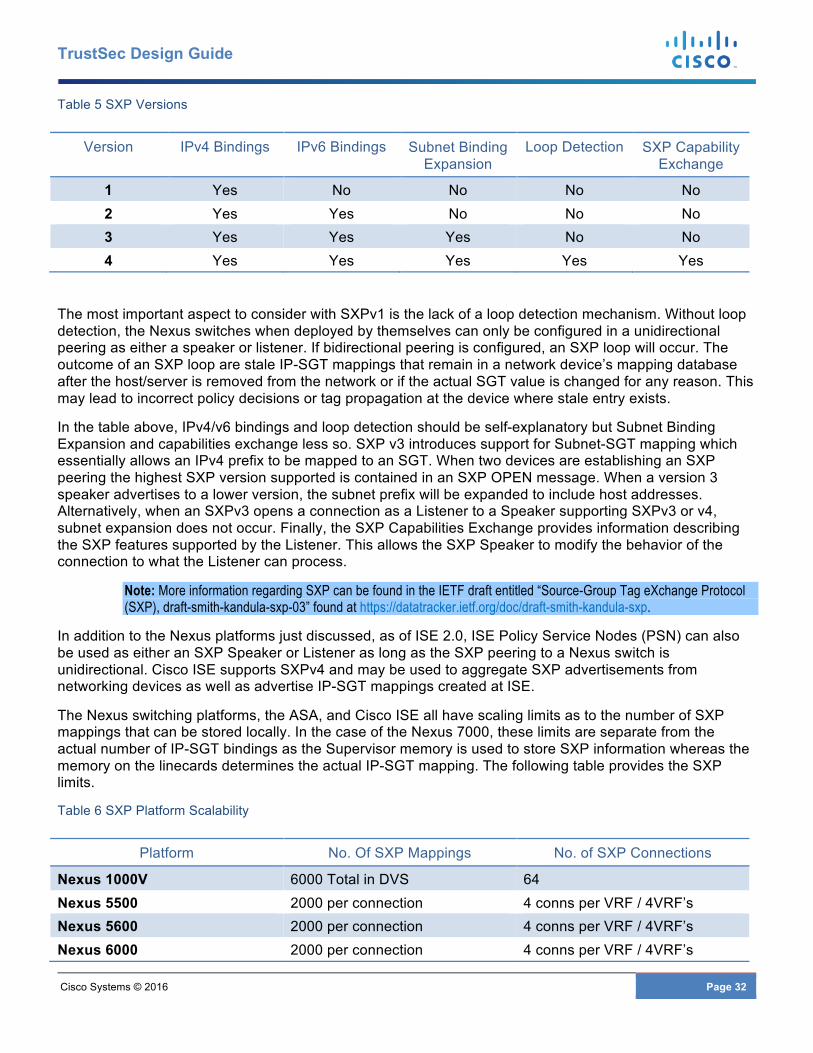
Cisco Systems © 2016 Page 32
TrustSec Design Guide
Table 5 SXP Versions
Version IPv4 Bindings IPv6 Bindings Subnet Binding Expansion
Loop Detection SXP Capability Exchange
1 Yes No No No No 2 Yes Yes No No No 3 Yes Yes Yes No No 4 Yes Yes Yes Yes Yes
The most important aspect to consider with SXPv1 is the lack of a loop detection mechanism. Without loop detection, the Nexus switches when deployed by themselves can only be configured in a unidirectional peering as either a speaker or listener. If bidirectional peering is configured, an SXP loop will occur. The outcome of an SXP loop are stale IP-SGT mappings that remain in a network device’s mapping database after the host/server is removed from the network or if the actual SGT value is changed for any reason. This may lead to incorrect policy decisions or tag propagation at the device where stale entry exists.
In the table above, IPv4/v6 bindings and loop detection should be self-explanatory but Subnet Binding Expansion and capabilities exchange less so. SXP v3 introduces support for Subnet-SGT mapping which essentially allows an IPv4 prefix to be mapped to an SGT. When two devices are establishing an SXP peering the highest SXP version supported is contained in an SXP OPEN message. When a version 3 speaker advertises to a lower version, the subnet prefix will be expanded to include host addresses. Alternatively, when an SXPv3 opens a connection as a Listener to a Speaker supporting SXPv3 or v4, subnet expansion does not occur. Finally, the SXP Capabilities Exchange provides information describing the SXP features supported by the Listener. This allows the SXP Speaker to modify the behavior of the connection to what the Listener can process.
Note: More information regarding SXP can be found in the IETF draft entitled “Source-Group Tag eXchange Protocol (SXP), draft-smith-kandula-sxp-03” found at https://datatracker.ietf.org/doc/draft-smith-kandula-sxp.
In addition to the Nexus platforms just discussed, as of ISE 2.0, ISE Policy Service Nodes (PSN) can also be used as either an SXP Speaker or Listener as long as the SXP peering to a Nexus switch is unidirectional. Cisco ISE supports SXPv4 and may be used to aggregate SXP advertisements from networking devices as well as advertise IP-SGT mappings created at ISE.
The Nexus switching platforms, the ASA, and Cisco ISE all have scaling limits as to the number of SXP mappings that can be stored locally. In the case of the Nexus 7000, these limits are separate from the actual number of IP-SGT bindings as the Supervisor memory is used to store SXP information whereas the memory on the linecards determines the actual IP-SGT mapping. The following table provides the SXP limits.
Table 6 SXP Platform Scalability
Platform No. Of SXP Mappings No. of SXP Connections
Nexus 1000V 6000 Total in DVS 64 Nexus 5500 2000 per connection 4 conns per VRF / 4VRF’s Nexus 5600 2000 per connection 4 conns per VRF / 4VRF’s Nexus 6000 2000 per connection 4 conns per VRF / 4VRF’s
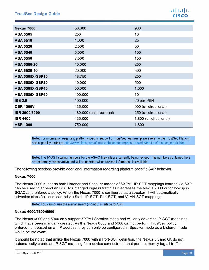
Cisco Systems © 2016 Page 33
TrustSec Design Guide
Nexus 7000 50,000 980 ASA 5505 250 10 ASA 5510 1,000 25 ASA 5520 2,500 50 ASA 5540 5,000 100 ASA 5550 7,500 150 ASA 5580-20 10,000 250 ASA 5580-40 20,000 500 ASA 5585X-SSP10 18,750 250 ASA 5585X-SSP20 10,000 500 ASA 5585X-SSP40 50,000 1,000 ASA 5585X-SSP60 100,000 10 ISE 2.0 100,000 20 per PSN CSR 1000V 135,000 900 (unidirectional) ISR 2900/3900 180,000 (unidirectional) 250 (unidirectional) ISR 4400 135,000 1,800 (unidirectional) ASR 1000 750,000 1,800
Note: For information regarding platform-specific support of TrustSec features, please refer to the TrustSec Platform and capability matrix at http://www.cisco.com/c/en/us/solutions/enterprise-networks/trustsec/trustsec_matrix.html
Note: The IP-SGT scaling numbers for the ASA-X firewalls are currently being revised. The numbers contained here are extremely conservative and will be updated when revised information is available.
The following sections provide additional information regarding platform-specific SXP behavior.
Nexus 7000
The Nexus 7000 supports both Listener and Speaker modes of SXPv1. IP-SGT mappings learned via SXP can be used to append an SGT to untagged ingress traffic as it egresses the Nexus 7000 or for lookup in SGACLs to enforce a policy. When the Nexus 7000 is configured as a speaker, it will automatically advertise classifications learned via Static IP-SGT, Port-SGT, and VLAN-SGT mappings.
Note: You cannot use the management (mgmt 0) interface for SXP.
Nexus 6000/5600/5500
The Nexus 6000 and 5000 only support SXPv1 Speaker mode and will only advertise IP-SGT mappings which have been manually created. As the Nexus 6000 and 5000 cannot perform TrustSec policy enforcement based on an IP address, they can only be configured in Speaker mode as a Listener mode would be irrelevant.
It should be noted that unlike the Nexus 7000 with a Port-SGT definition, the Nexus 5K and 6K do not automatically create an IP-SGT mapping for a device connected to that port but merely tag all traffic
Cisco Systems © 2016 Page 34
TrustSec Design Guide
received on the port without any IP inspection. As such a manual IP-SGT definition must be created for use with SXP.
For the Nexus 6000 and 5000 family of switches, the management interface cannot be used as the source IP address for an SXP connection. Therefore, the Nexus 6000 or 5000 must use an SVI or a loopback interface. Typically, a new VLAN with an associated SVI will need to be created for terminating the SXP connection as the VLAN used must not have CTS enforcement enabled on it. The following error will occur; “ERROR: Router SVI not allowed since CTS is enforced on the VLAN X”.
Note: The Nexus 5010/5020 and 3000 series of switches do not support TrustSec.
Nexus 1000V
The Nexus 1000V supports SXP v1 Listener and Speaker modes. All SXP connections either sourced from or directed to the Nexus 1000V must be configured to use the management IP address in the “management” VRF.
The Nexus 1000V will advertise classifications resulting from the port profile configuration assigned to a VM. As a virtual machine’s network connection comes up using the assigned Nexus port profile, IP Device tracking on the Nexus 1000V detects the new device. This device tracking information is then used to populate the local IP-SGT database which can be used to advertise that mapping if SXP speaker mode has been configured.
Mappings received via SXP at the Nexus 1000V can also be used for policy enforcement purposes through SGACLs on the device. These mappings can be used for traffic leaving the N1KV Virtual Ethernet Module (VEM) on the physical host server. For enforcement purposes, SGT propagation must be configured on the VEM uplink ports; this will be discussed later in enforcement.
Note: Although the Nexus 1000V is supported on VMware, Hyper-V, KVM, and Citrix XenServer, TrustSec is only supported for VMware at this time.
ASAs
Even though inline tagging is supported on the ASA 5505, 5512, 5515, 5525, 5545, 5555, and 5585 and the “X” series firewalls in version 9.3.1, SXP is the only means by which the SGT can be propagated to older firewalls such as the ASA 5510, 5520, 5540, 5550, and the 5580. Additionally, although possible to configure inline tagging on all interfaces of the firewall, SXP will still typically be used to advertise the servers’ IP-SGT mappings to the firewall for those servers protected by the firewall. This will be discussed in the following section discussing Common scenarios for SXP usage in the Data Center.
Today, the ASA supports SXPv2 but in the first half of 2016 in software version 9.6 it will pick up support for SXPv3. With SXPv3 the ASA will be able to not only create policies based on IP-SGT mappings but on Subnet-SGT mappings without the need to expand subnets to the host addresses within.
The ASA supports both SXP speaker and listener mode however, as loop detection found in SXPv4 is unavailable, only a unidirectional peering should ever be made between the ASA and its peer. When defining the source interface for SXP connections, it is highly recommended that the Management interface be used. However, if not possible, either the outside interface, for Routed Mode or the BVI interface, for Transparent Mode, can be used to terminate the SXP peering. The only reason the management interface is preferred is simply for performance considerations.
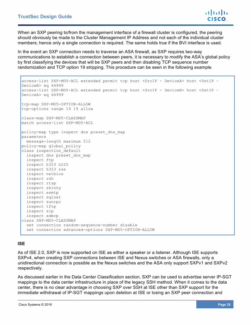
Cisco Systems © 2016 Page 35
TrustSec Design Guide
When an SXP peering to/from the management interface of a firewall cluster is configured, the peering should obviously be made to the Cluster Management IP Address and not each of the individual cluster members; hence only a single connection is required. The same holds true if the BVI interface is used.
In the event an SXP connection needs to traverse an ASA firewall, as SXP requires two-way communications to establish a connection between peers, it is necessary to modify the ASA’s global policy by first classifying the devices that will be SXP peers and then disabling TCP sequence number randomization and TCP option 19 stripping. This procedure can be seen in the following example.
access-list SXP-MD5-ACL extended permit tcp host <SrcIP - DeviceA> host <DstIP – DeviceB> eq 64999 access-list SXP-MD5-ACL extended permit tcp host <SrcIP - DeviceB> host <DstIP – DeviceA> eq 64999 tcp-map SXP-MD5-OPTION-ALLOW tcp-options range 19 19 allow class-map SXP-MD5-CLASSMAP match access-list SXP-MD5-ACL policy-map type inspect dns preset_dns_map parameters message-length maximum 512 policy-map global_policy class inspection_default inspect dns preset_dns_map inspect ftp inspect h323 h225 inspect h323 ras inspect netbios inspect rsh inspect rtsp inspect skinny inspect esmtp inspect sqlnet inspect sunrpc inspect tftp inspect sip inspect xdmcp class SXP-MD5-CLASSMAP set connection random-sequence-number disable set connection advanced-options SXP-MD5-OPTION-ALLOW
ISE
As of ISE 2.0, SXP is now supported on ISE as either a speaker or a listener. Although ISE supports SXPv4, when creating SXP connections between ISE and Nexus switches or ASA firewalls, only a unidirectional connection is possible as the Nexus switches and the ASA only support SXPv1 and SXPv2 respectively.
As discussed earlier in the Data Center Classification section, SXP can be used to advertise server IP-SGT mappings to the data center infrastructure in place of the legacy SSH method. When it comes to the data center, there is no clear advantage in choosing SXP over SSH at ISE other than SXP support for the immediate withdrawal of IP-SGT mappings upon deletion at ISE or losing an SXP peer connection and

Cisco Systems © 2016 Page 36
TrustSec Design Guide
hence all of the mappings advertised by same. The one consideration that may come into play is the fact that the Nexus 7000 is limited to 50,000 SXP mappings.
The real benefit of SXP at ISE derives from the ability to automatically advertise campus access layer mappings into the data center, typically a Nexus 7000 or ASA firewall cluster. If doing this though, extreme care must be taken to ensure that the platform has sufficient resources to accommodate those mappings per 0 above.
It is beyond the scope of this document to provide deployment guidance around implementing SXP in ISE. The information provided within will simply discuss enabling SXP, defining SXP peers, and creating static SXP mappings at ISE.
Note: Although SXP can be enabled on a standalone ISE server running all personas, it is strongly recommended that you run the SXP service on a dedicated Policy Service Node (PSN) or Nodes in an ISE Distributed Deployment Model.
SXP Reflector
In certain instances, when SXP is used, it may be desirable to centralize SXP advertisements within the data center to a device other than a Nexus 7000. In these instances an ASR1000 or ISR router may be used as a centralized peering point or “SXP Reflector” to which all SXP advertisements are aggregated with a single peering extending from the router to elsewhere in the datacenter such as an ASA or even the campus. A perfect analogy for an SXP Reflector can be drawn to a BGP Reflector and how it is used to eliminate the full mesh of iBGP peers required to exchange routes.
It must be noted that although the routers support SXPv4 loop detection, a bidirectional peering should never be configured to non-SXPv4 devices such as the ASA or a Nexus switch. As such, any SXP connection to a non-SXPv4 device must be unidirectional.
Note: An SXP reflector should be deployed as a pair of routers with a peering established from each access switch to each reflector for high availability.
An example of a typical use of an SXP reflector can be seen in 0 below where the various datacenter access switches peer to an ASR1K used as an SXP reflector which in turn peers to the ASA.

Cisco Systems © 2016 Page 37
TrustSec Design Guide
Figure 13 SXP Reflector aggregating SXP advertisements
Common Scenarios for use of SXP in the Data Center
Three exceptions where inline tagging may not be suitable are when third party switching products including various hypervisor vSwitches are used, L2 transport services such as OTV, and the use of the ASA as an SGFW.
Third Party Switches
When dealing with third party switching products, if the switch is a transit device between two TrustSec-capable switches, SXP can be used to advertise IP-SGT mappings over the top of the third party switch as seen in Figure 14 below. If however the server is attached directly to a third party switch, the only option will be to classify the servers attached to that switch at the Nexus 7000 in Figure 14 by either IP-SGT mappings defined at Nexus 7000 or ISE or through the use of static VLAN-SGT mappings defined at the Nexus 7000.
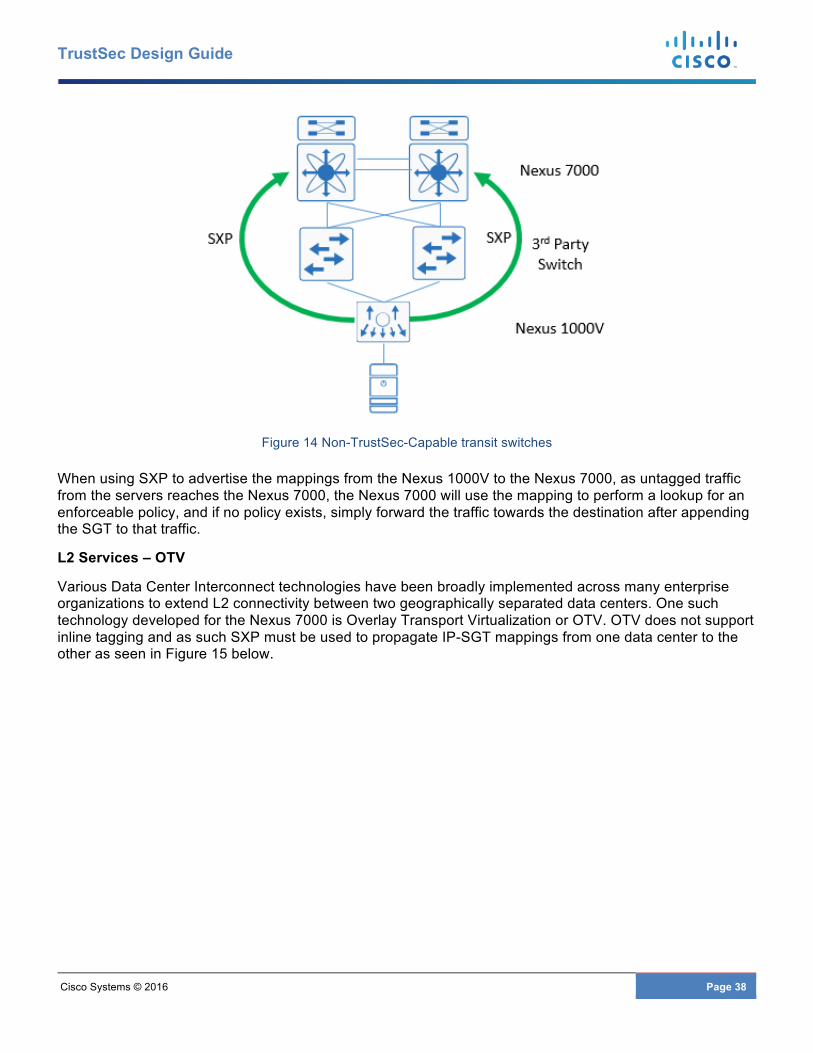
Cisco Systems © 2016 Page 38
TrustSec Design Guide
Figure 14 Non-TrustSec-Capable transit switches
When using SXP to advertise the mappings from the Nexus 1000V to the Nexus 7000, as untagged traffic from the servers reaches the Nexus 7000, the Nexus 7000 will use the mapping to perform a lookup for an enforceable policy, and if no policy exists, simply forward the traffic towards the destination after appending the SGT to that traffic.
L2 Services – OTV
Various Data Center Interconnect technologies have been broadly implemented across many enterprise organizations to extend L2 connectivity between two geographically separated data centers. One such technology developed for the Nexus 7000 is Overlay Transport Virtualization or OTV. OTV does not support inline tagging and as such SXP must be used to propagate IP-SGT mappings from one data center to the other as seen in Figure 15 below.
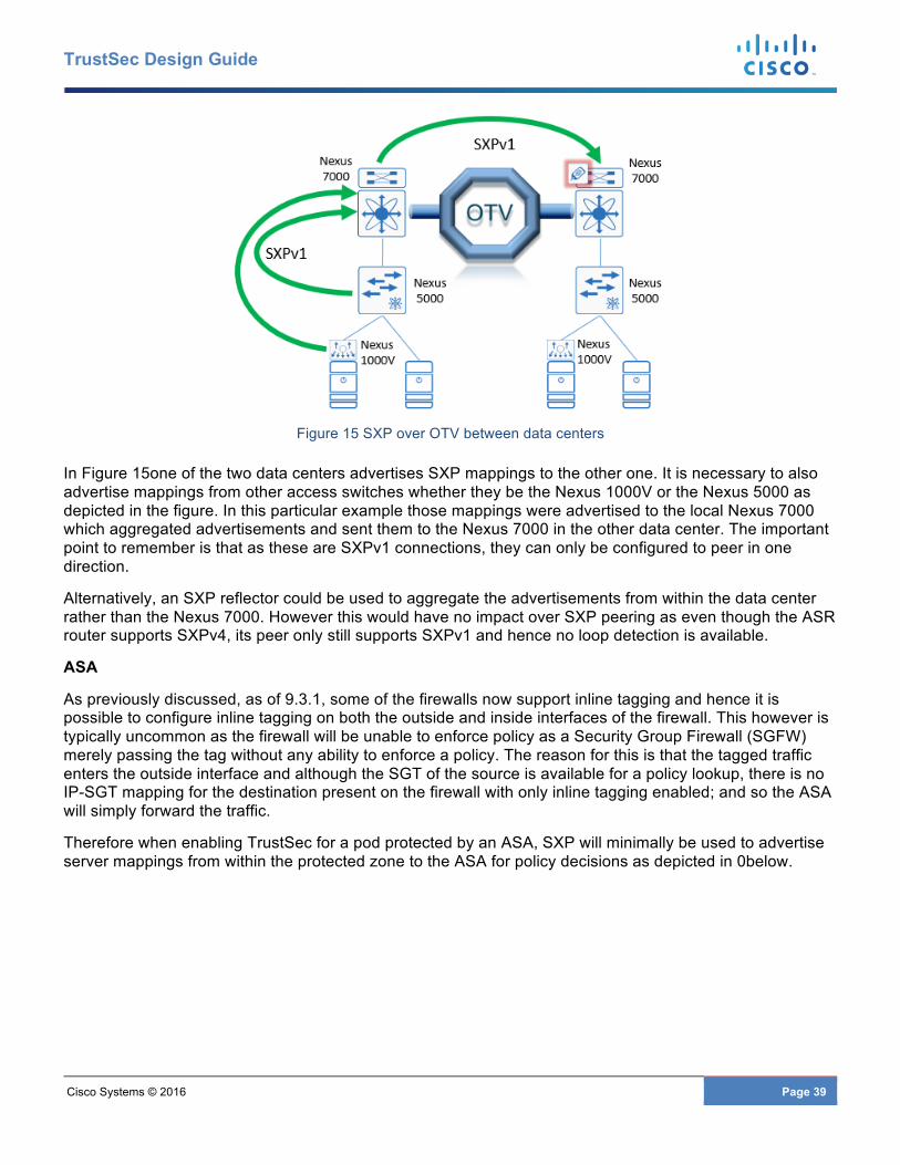
Cisco Systems © 2016 Page 39
TrustSec Design Guide
Figure 15 SXP over OTV between data centers
In Figure 15one of the two data centers advertises SXP mappings to the other one. It is necessary to also advertise mappings from other access switches whether they be the Nexus 1000V or the Nexus 5000 as depicted in the figure. In this particular example those mappings were advertised to the local Nexus 7000 which aggregated advertisements and sent them to the Nexus 7000 in the other data center. The important point to remember is that as these are SXPv1 connections, they can only be configured to peer in one direction.
Alternatively, an SXP reflector could be used to aggregate the advertisements from within the data center rather than the Nexus 7000. However this would have no impact over SXP peering as even though the ASR router supports SXPv4, its peer only still supports SXPv1 and hence no loop detection is available.
ASA
As previously discussed, as of 9.3.1, some of the firewalls now support inline tagging and hence it is possible to configure inline tagging on both the outside and inside interfaces of the firewall. This however is typically uncommon as the firewall will be unable to enforce policy as a Security Group Firewall (SGFW) merely passing the tag without any ability to enforce a policy. The reason for this is that the tagged traffic enters the outside interface and although the SGT of the source is available for a policy lookup, there is no IP-SGT mapping for the destination present on the firewall with only inline tagging enabled; and so the ASA will simply forward the traffic.
Therefore when enabling TrustSec for a pod protected by an ASA, SXP will minimally be used to advertise server mappings from within the protected zone to the ASA for policy decisions as depicted in 0below.
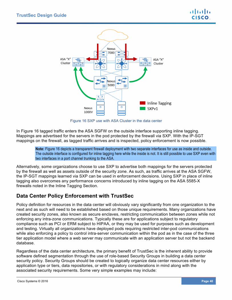
Cisco Systems © 2016 Page 40
TrustSec Design Guide
Figure 16 SXP use with ASA Cluster in the data center
In Figure 16 tagged traffic enters the ASA SGFW on the outside interface supporting inline tagging. Mappings are advertised for the servers in the pod protected by the firewall via SXP. With the IP-SGT mappings on the firewall, as tagged traffic arrives and is inspected, policy enforcement is now possible.
Note: Figure 16 depicts a transparent firewall deployment with two separate interfaces for use as inside and outside. The outside interface is configured for inline tagging here while the inside is not. It is still possible to use SXP even with two interfaces in a port channel trunking to the ASA.
Alternatively, some organizations choose to use SXP to advertise both mappings for the servers protected by the firewall as well as assets outside of the security zone. As such, as traffic arrives at the ASA SGFW, the IP-SGT mappings learned via SXP can be used in enforcement decisions. Using SXP in place of inline tagging also overcomes any performance concerns introduced by inline tagging on the ASA 5585-X firewalls noted in the Inline Tagging Section.
Data Center Policy Enforcement with TrustSec Policy definition for resources in the data center will obviously vary significantly from one organization to the next and as such will need to be established based on those unique requirements. Many organizations have created security zones, also known as secure enclaves, restricting communication between zones while not enforcing any intra-zone communications. Typically these are for applications subject to regulatory compliance such as PCI or ERM subject to HIPAA, or they may be used for purposes such as development and testing. Virtually all organizations have deployed pods requiring restricted inter-pod communications while also enforcing a policy to control intra-server communication within the pod as in the case of the three tier application model where a web server may communicate with an application server but not the backend database.
Regardless of the data center architecture, the primary benefit of TrustSec is the inherent ability to provide software defined segmentation through the use of role-based Security Groups in building a data center security policy. Security Groups should be created to logically organize data center resources either by application type or tiers, data repositories, or with regulatory considerations in mind along with the associated security requirements. Some very simple examples may include:
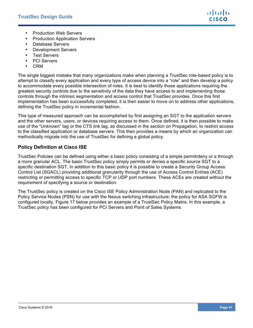
Cisco Systems © 2016 Page 41
TrustSec Design Guide
• Production Web Servers • Production Application Servers • Database Servers • Development Servers • Test Servers • PCI Servers • CRM
The single biggest mistake that many organizations make when planning a TrustSec role-based policy is to attempt to classify every application and every type of access device into a “role” and then develop a policy to accommodate every possible intersection of roles. It is best to identify those applications requiring the greatest security controls due to the sensitivity of the data they have access to and implementing those controls through the intrinsic segmentation and access control that TrustSec provides. Once this first implementation has been successfully completed, it is then easier to move on to address other applications, defining the TrustSec policy in incremental fashion.
This type of measured approach can be accomplished by first assigning an SGT to the application servers and the other servers, users, or devices requiring access to them. Once defined, it is then possible to make use of the “Unknown” tag or the CTS link tag, as discussed in the section on Propagation, to restrict access to the classified application or database servers. This then provides a means by which an organization can methodically migrate into the use of TrustSec for defining a global policy.
Policy Definition at Cisco ISE
TrustSec Policies can be defined using either a basic policy consisting of a simple permit/deny or a through a more granular ACL. The basic TrustSec policy simply permits or denies a specific source SGT to a specific destination SGT. In addition to this basic policy it is possible to create a Security Group Access Control List (SGACL) providing additional granularity through the use of Access Control Entries (ACE) restricting or permitting access to specific TCP or UDP port numbers. These ACEs are created without the requirement of specifying a source or destination.
The TrustSec policy is created on the Cisco ISE Policy Administration Node (PAN) and replicated to the Policy Service Nodes (PSN) for use with the Nexus switching infrastructure; the policy for ASA SGFW is configured locally. Figure 17 below provides an example of a TrustSec Policy Matrix. In this example, a TrustSec policy has been configured for PCI Servers and Point of Sales Systems.
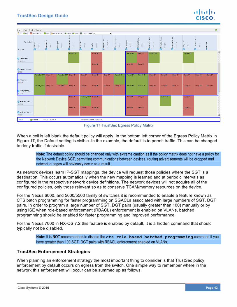
Cisco Systems © 2016 Page 42
TrustSec Design Guide
Figure 17 TrustSec Egress Policy Matrix
When a cell is left blank the default policy will apply. In the bottom left corner of the Egress Policy Matrix in Figure 17, the Default setting is visible. In the example, the default is to permit traffic. This can be changed to deny traffic if desirable.
Note: The default policy should be changed only with extreme caution as if the policy matrix does not have a policy for the Network Device SGT, permitting communications between devices, routing advertisements will be dropped and network outages will obviously occur as a result.
As network devices learn IP-SGT mappings, the device will request those policies where the SGT is a destination. This occurs automatically when the new mapping is learned and at periodic intervals as configured in the respective network device definitions. The network devices will not acquire all of the configured policies, only those relevant so as to conserve TCAM/memory resources on the device.
For the Nexus 6000, and 5600/5500 family of switches it is recommended to enable a feature known as CTS batch programming for faster programming on SGACLs associated with large numbers of SGT, DGT pairs. In order to program a large number of SGT, DGT pairs (usually greater than 100) manually or by using ISE when role-based enforcement (RBACL) enforcement is enabled on VLANs, batched programming should be enabled for faster programming and improved performance.
For the Nexus 7000 in NX-OS 7.2 this feature is enabled by default. It is a hidden command that should typically not be disabled.
Note: It is NOT recommended to disable the cts role-based batched-programming command if you have greater than 100 SGT, DGT pairs with RBACL enforcement enabled on VLANs.
TrustSec Enforcement Strategies
When planning an enforcement strategy the most important thing to consider is that TrustSec policy enforcement by default occurs on egress from the switch. One simple way to remember where in the network this enforcement will occur can be summed up as follows.
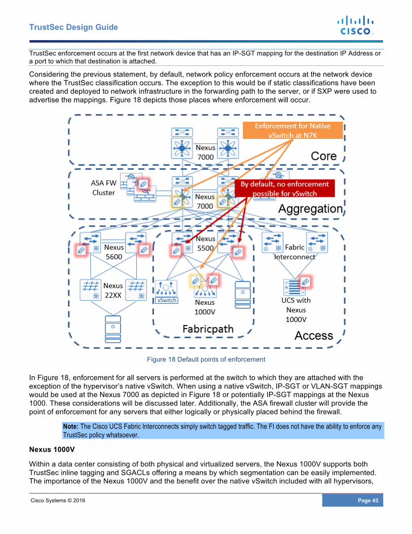
Cisco Systems © 2016 Page 43
TrustSec Design Guide
TrustSec enforcement occurs at the first network device that has an IP-SGT mapping for the destination IP Address or a port to which that destination is attached.
Considering the previous statement, by default, network policy enforcement occurs at the network device where the TrustSec classification occurs. The exception to this would be if static classifications have been created and deployed to network infrastructure in the forwarding path to the server, or if SXP were used to advertise the mappings. Figure 18 depicts those places where enforcement will occur.
Figure 18 Default points of enforcement
In Figure 18, enforcement for all servers is performed at the switch to which they are attached with the exception of the hypervisor’s native vSwitch. When using a native vSwitch, IP-SGT or VLAN-SGT mappings would be used at the Nexus 7000 as depicted in Figure 18 or potentially IP-SGT mappings at the Nexus 1000. These considerations will be discussed later. Additionally, the ASA firewall cluster will provide the point of enforcement for any servers that either logically or physically placed behind the firewall.
Note: The Cisco UCS Fabric Interconnects simply switch tagged traffic. The FI does not have the ability to enforce any TrustSec policy whatsoever.
Nexus 1000V
Within a data center consisting of both physical and virtualized servers, the Nexus 1000V supports both TrustSec inline tagging and SGACLs offering a means by which segmentation can be easily implemented. The importance of the Nexus 1000V and the benefit over the native vSwitch included with all hypervisors,
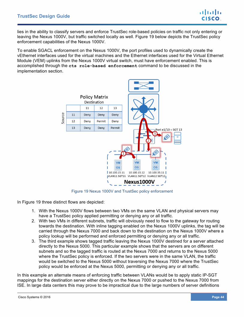
Cisco Systems © 2016 Page 44
TrustSec Design Guide
lies in the ability to classify servers and enforce TrustSec role-based policies on traffic not only entering or leaving the Nexus 1000V, but traffic switched locally as well. Figure 19 below depicts the TrustSec policy enforcement capabilities of the Nexus 1000V.
To enable SGACL enforcement on the Nexus 1000V, the port profiles used to dynamically create the vEthernet interfaces used for the virtual machines and the Ethernet interfaces used for the Virtual Ethernet Module (VEM) uplinks from the Nexus 1000V virtual switch, must have enforcement enabled. This is accomplished through the cts role-based enforcement command to be discussed in the implementation section.
Figure 19 Nexus 1000V and TrustSec policy enforcement
In Figure 19 three distinct flows are depicted:
1. With the Nexus 1000V flows between two VMs on the same VLAN and physical servers may have a TrustSec policy applied permitting or denying any or all traffic.
2. With two VMs in different subnets, traffic will obviously need to flow to the gateway for routing towards the destination. With inline tagging enabled on the Nexus 1000V uplinks, the tag will be carried through the Nexus 7000 and back down to the destination on the Nexus 1000V where a policy lookup will be performed and enforced permitting or denying any or all traffic.
3. The third example shows tagged traffic leaving the Nexus 1000V destined for a server attached directly to the Nexus 5000. This particular example shows that the servers are on different subnets and so the tagged traffic is routed at the Nexus 7000 and returns to the Nexus 5000 where the TrustSec policy is enforced. If the two servers were in the same VLAN, the traffic would be switched to the Nexus 5000 without traversing the Nexus 7000 where the TrustSec policy would be enforced at the Nexus 5000, permitting or denying any or all traffic.
In this example an alternate means of enforcing traffic between VLANs would be to apply static IP-SGT mappings for the destination server either directly on the Nexus 7000 or pushed to the Nexus 7000 from ISE. In large data centers this may prove to be impractical due to the large numbers of server definitions

Cisco Systems © 2016 Page 45
TrustSec Design Guide
that would need to be created as well as the potential resources they may consume on the Nexus 7000. With inline tagging possible throughout the data center it would be recommended to forward the tagged traffic and enforce the policy on the network device where the destination is attached.
From the earlier section on Classification for the Nexus 1000V, the port profile configuration is where the SGT is defined. As a VM is powered on and the vEthernet port on the Nexus 1000V comes up, IP device tracking is used to learn the IP-SGT mapping of the server. It is these mappings learned via device tracking that are used to enforce TrustSec policies between VMs in the same VLAN within the same host, or servers in the same VLAN extending across the Nexus 1000V Virtual Distributed Switch (VDS), between two hosts as depicted in Figure 20 below.
Figure 20 Nexus 1000 and TrustSec policy enforcement across L2 VDS
In Figure 20 traffic from the VM with IP address 10.100.15.11 is leaving the Nexus 1000V Virtual Ethernet Module (VEM) on the server “Corp_100” destined for 10.100.15.14 on the server “Corp_200” which is associated with VEM2. The traffic on egress from VEM1 is tagged and forwarded to the Nexus 5000 which then switches it on to VEM2. Upon arrival at VEM2, the SGT is inspected and lookup performed for TrustSec policy enforcement. The traffic is either permitted or denied base on the SGACL.
It is possible to utilize static IP-SGT mappings and SXP information on the Nexus 1000V to be used in policy lookups. The static IP-SGT mappings can be created locally or at Cisco ISE and when using SXP mappings, the Nexus 1000V would obviously be configured in an SXP listener role. Caution should be exercised when configuring SXP as the Nexus 1000V only supports SXPv1 and hence bidirectional peering must be avoided. These mappings can only be used for policy lookup of traffic egressing the Nexus 1000V and not entering it. As such the specific policy rule that will be used is when the source is a server attached to the Nexus 1000V and the destination is present as one of the statically defined or SXP mappings. The example in Figure 21 below depicts this behavior.
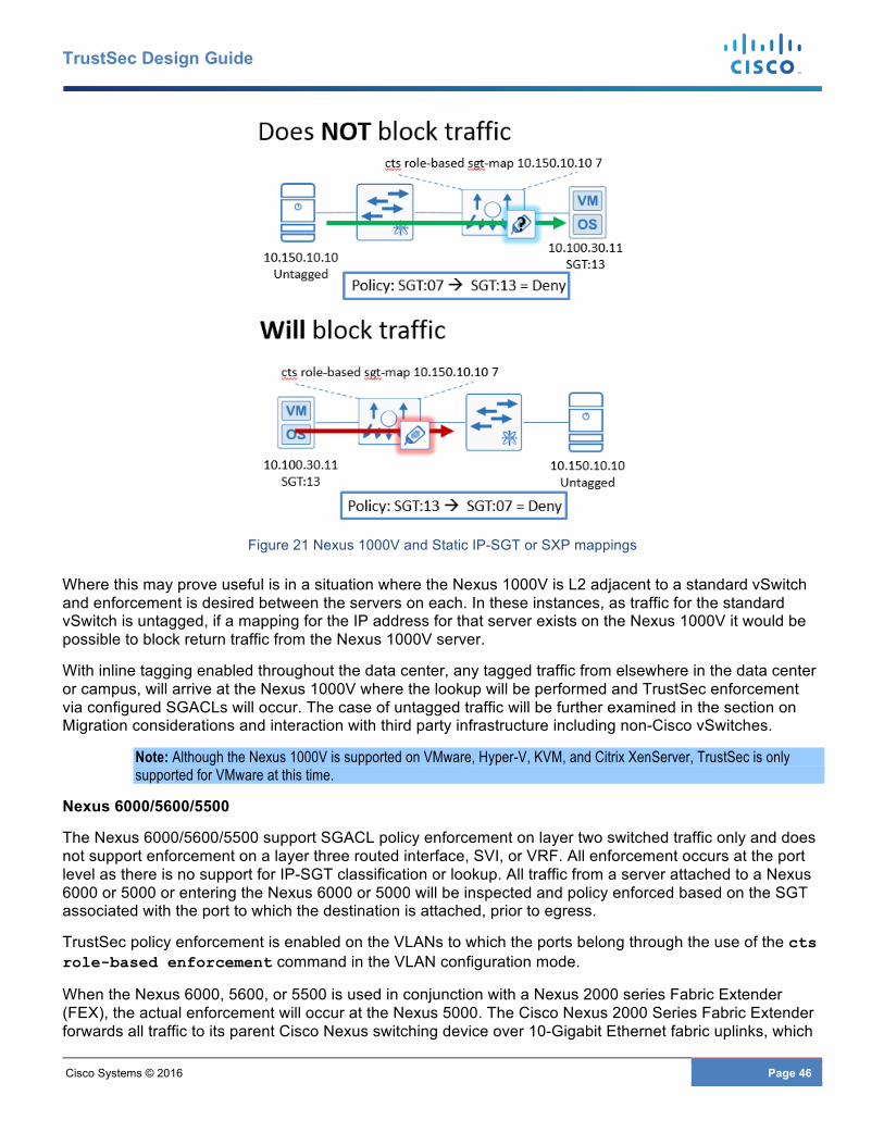
Cisco Systems © 2016 Page 46
TrustSec Design Guide
Figure 21 Nexus 1000V and Static IP-SGT or SXP mappings
Where this may prove useful is in a situation where the Nexus 1000V is L2 adjacent to a standard vSwitch and enforcement is desired between the servers on each. In these instances, as traffic for the standard vSwitch is untagged, if a mapping for the IP address for that server exists on the Nexus 1000V it would be possible to block return traffic from the Nexus 1000V server.
With inline tagging enabled throughout the data center, any tagged traffic from elsewhere in the data center or campus, will arrive at the Nexus 1000V where the lookup will be performed and TrustSec enforcement via configured SGACLs will occur. The case of untagged traffic will be further examined in the section on Migration considerations and interaction with third party infrastructure including non-Cisco vSwitches.
Note: Although the Nexus 1000V is supported on VMware, Hyper-V, KVM, and Citrix XenServer, TrustSec is only supported for VMware at this time.
Nexus 6000/5600/5500
The Nexus 6000/5600/5500 support SGACL policy enforcement on layer two switched traffic only and does not support enforcement on a layer three routed interface, SVI, or VRF. All enforcement occurs at the port level as there is no support for IP-SGT classification or lookup. All traffic from a server attached to a Nexus 6000 or 5000 or entering the Nexus 6000 or 5000 will be inspected and policy enforced based on the SGT associated with the port to which the destination is attached, prior to egress.
TrustSec policy enforcement is enabled on the VLANs to which the ports belong through the use of the cts role-based enforcement command in the VLAN configuration mode.
When the Nexus 6000, 5600, or 5500 is used in conjunction with a Nexus 2000 series Fabric Extender (FEX), the actual enforcement will occur at the Nexus 5000. The Cisco Nexus 2000 Series Fabric Extender forwards all traffic to its parent Cisco Nexus switching device over 10-Gigabit Ethernet fabric uplinks, which
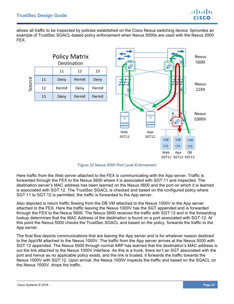
Cisco Systems © 2016 Page 47
TrustSec Design Guide
allows all traffic to be inspected by policies established on the Cisco Nexus switching device. 0provides an example of TrustSec SGACL-based policy enforcement when Nexus 5000s are used with the Nexus 2000 FEX.
Figure 22 Nexus 5000 Port Level Enforcement
Here traffic from the Web server attached to the FEX is communicating with the App server. Traffic is forwarded through the FEX to the Nexus 5600 where it is associated with SGT:11 and inspected. The destination server’s MAC address has been learned on the Nexus 5600 and the port on which it is learned is associated with SGT:12. The TrustSec SGACL is checked and based on the configured policy where SGT:11 to SGT:12 is permitted, the traffic is forwarded to the App server.
Also depicted is return traffic flowing from the DB VM attached to the Nexus 1000V to the App server attached to the FEX. Here the traffic leaving the Nexus 1000V has the SGT appended and is forwarded through the FEX to the Nexus 5600. The Nexus 5600 receives the traffic with SGT:13 and in the forwarding lookup determines that the MAC Address of the destination is found on a port associated with SGT:12. At this point the Nexus 5000 checks the TrustSec SGACL and based on the policy, forwards the traffic to the App server.
The final flow depicts communications that are leaving the App server and is for whatever reason destined to the AppVM attached to the Nexus 1000V. The traffic from the App server arrives at the Nexus 5000 with SGT:12 appended. The Nexus 5000 through normal ARP has learned that the destination’s MAC address is out the link attached to the Nexus 1000V interface. As this is a trunk, there isn’t an SGT associated with the port and hence as no applicable policy exists, and the link is trusted, it forwards the traffic towards the Nexus 1000V with SGT:12. Upon arrival, the Nexus 1000V inspects the traffic and based on the SGACL on the Nexus 1000V, drops the traffic.
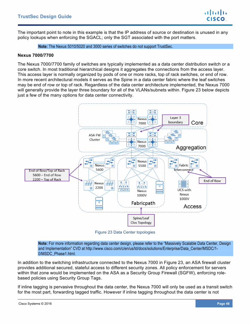
Cisco Systems © 2016 Page 48
TrustSec Design Guide
The important point to note in this example is that the IP address of source or destination is unused in any policy lookups when enforcing the SGACL; only the SGT associated with the port matters.
Note: The Nexus 5010/5020 and 3000 series of switches do not support TrustSec.
Nexus 7000/7700
The Nexus 7000/7700 family of switches are typically implemented as a data center distribution switch or a core switch. In most traditional hierarchical designs it aggregates the connections from the access layer. This access layer is normally organized by pods of one or more racks, top of rack switches, or end of row. In more recent architectural models it serves as the Spine in a data center fabric where the leaf switches may be end of row or top of rack. Regardless of the data center architecture implemented, the Nexus 7000 will generally provide the layer three boundary for all of the VLANs/subnets within. Figure 23 below depicts just a few of the many options for data center connectivity.
Figure 23 Data Center topologies
Note: For more information regarding data center design, please refer to the “Massively Scalable Data Center, Design and Implementation” CVD at http://www.cisco.com/c/en/us/td/docs/solutions/Enterprise/Data_Center/MSDC/1-0/MSDC_Phase1.html.
In addition to the switching infrastructure connected to the Nexus 7000 in Figure 23, an ASA firewall cluster provides additional secured, stateful access to different security zones. All policy enforcement for servers within that zone would be implemented on the ASA as a Security Group Firewall (SGFW), enforcing role-based policies using Security Group Tags.
If inline tagging is pervasive throughout the data center, the Nexus 7000 will only be used as a transit switch for the most part, forwarding tagged traffic. However if inline tagging throughout the data center is not
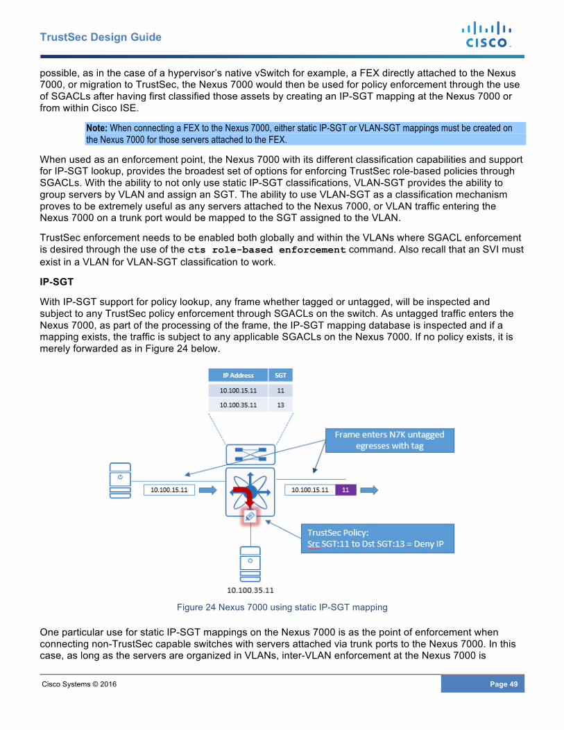
Cisco Systems © 2016 Page 49
TrustSec Design Guide
possible, as in the case of a hypervisor’s native vSwitch for example, a FEX directly attached to the Nexus 7000, or migration to TrustSec, the Nexus 7000 would then be used for policy enforcement through the use of SGACLs after having first classified those assets by creating an IP-SGT mapping at the Nexus 7000 or from within Cisco ISE.
Note: When connecting a FEX to the Nexus 7000, either static IP-SGT or VLAN-SGT mappings must be created on the Nexus 7000 for those servers attached to the FEX.
When used as an enforcement point, the Nexus 7000 with its different classification capabilities and support for IP-SGT lookup, provides the broadest set of options for enforcing TrustSec role-based policies through SGACLs. With the ability to not only use static IP-SGT classifications, VLAN-SGT provides the ability to group servers by VLAN and assign an SGT. The ability to use VLAN-SGT as a classification mechanism proves to be extremely useful as any servers attached to the Nexus 7000, or VLAN traffic entering the Nexus 7000 on a trunk port would be mapped to the SGT assigned to the VLAN.
TrustSec enforcement needs to be enabled both globally and within the VLANs where SGACL enforcement is desired through the use of the cts role-based enforcement command. Also recall that an SVI must exist in a VLAN for VLAN-SGT classification to work.
IP-SGT
With IP-SGT support for policy lookup, any frame whether tagged or untagged, will be inspected and subject to any TrustSec policy enforcement through SGACLs on the switch. As untagged traffic enters the Nexus 7000, as part of the processing of the frame, the IP-SGT mapping database is inspected and if a mapping exists, the traffic is subject to any applicable SGACLs on the Nexus 7000. If no policy exists, it is merely forwarded as in Figure 24 below.
Figure 24 Nexus 7000 using static IP-SGT mapping
One particular use for static IP-SGT mappings on the Nexus 7000 is as the point of enforcement when connecting non-TrustSec capable switches with servers attached via trunk ports to the Nexus 7000. In this case, as long as the servers are organized in VLANs, inter-VLAN enforcement at the Nexus 7000 is
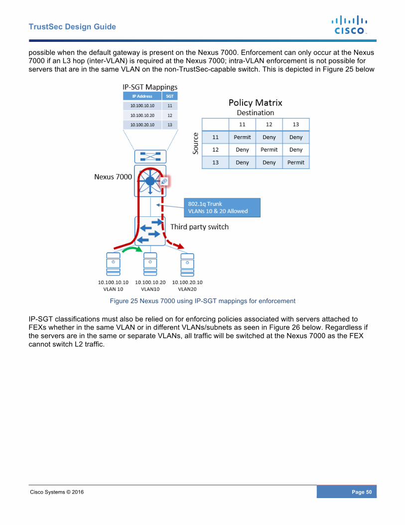
Cisco Systems © 2016 Page 50
TrustSec Design Guide
possible when the default gateway is present on the Nexus 7000. Enforcement can only occur at the Nexus 7000 if an L3 hop (inter-VLAN) is required at the Nexus 7000; intra-VLAN enforcement is not possible for servers that are in the same VLAN on the non-TrustSec-capable switch. This is depicted in Figure 25 below
Figure 25 Nexus 7000 using IP-SGT mappings for enforcement
IP-SGT classifications must also be relied on for enforcing policies associated with servers attached to FEXs whether in the same VLAN or in different VLANs/subnets as seen in Figure 26 below. Regardless if the servers are in the same or separate VLANs, all traffic will be switched at the Nexus 7000 as the FEX cannot switch L2 traffic.
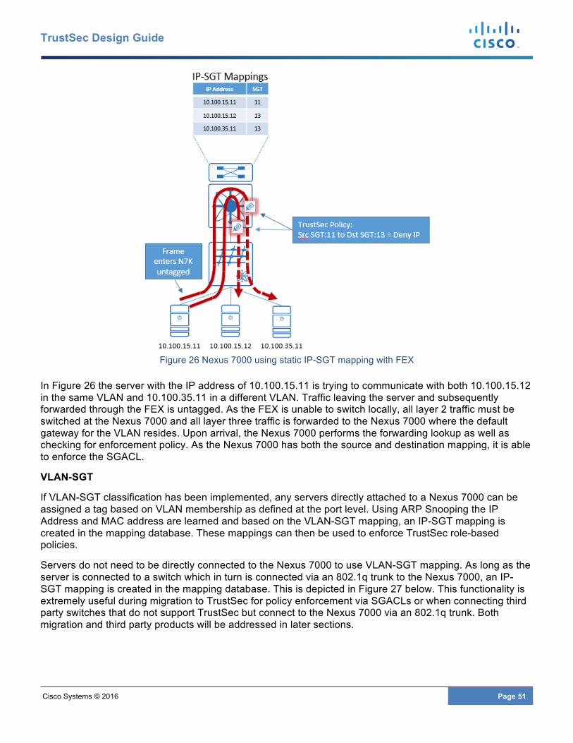
Cisco Systems © 2016 Page 51
TrustSec Design Guide
Figure 26 Nexus 7000 using static IP-SGT mapping with FEX
In Figure 26 the server with the IP address of 10.100.15.11 is trying to communicate with both 10.100.15.12 in the same VLAN and 10.100.35.11 in a different VLAN. Traffic leaving the server and subsequently forwarded through the FEX is untagged. As the FEX is unable to switch locally, all layer 2 traffic must be switched at the Nexus 7000 and all layer three traffic is forwarded to the Nexus 7000 where the default gateway for the VLAN resides. Upon arrival, the Nexus 7000 performs the forwarding lookup as well as checking for enforcement policy. As the Nexus 7000 has both the source and destination mapping, it is able to enforce the SGACL.
VLAN-SGT
If VLAN-SGT classification has been implemented, any servers directly attached to a Nexus 7000 can be assigned a tag based on VLAN membership as defined at the port level. Using ARP Snooping the IP Address and MAC address are learned and based on the VLAN-SGT mapping, an IP-SGT mapping is created in the mapping database. These mappings can then be used to enforce TrustSec role-based policies.
Servers do not need to be directly connected to the Nexus 7000 to use VLAN-SGT mapping. As long as the server is connected to a switch which in turn is connected via an 802.1q trunk to the Nexus 7000, an IP-SGT mapping is created in the mapping database. This is depicted in Figure 27 below. This functionality is extremely useful during migration to TrustSec for policy enforcement via SGACLs or when connecting third party switches that do not support TrustSec but connect to the Nexus 7000 via an 802.1q trunk. Both migration and third party products will be addressed in later sections.
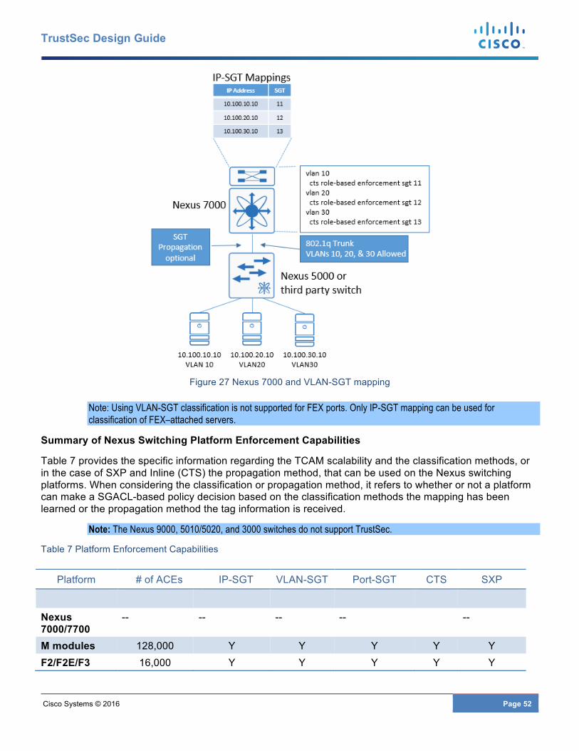
Cisco Systems © 2016 Page 52
TrustSec Design Guide
Figure 27 Nexus 7000 and VLAN-SGT mapping
Note: Using VLAN-SGT classification is not supported for FEX ports. Only IP-SGT mapping can be used for classification of FEX–attached servers.
Summary of Nexus Switching Platform Enforcement Capabilities
Table 7 provides the specific information regarding the TCAM scalability and the classification methods, or in the case of SXP and Inline (CTS) the propagation method, that can be used on the Nexus switching platforms. When considering the classification or propagation method, it refers to whether or not a platform can make a SGACL-based policy decision based on the classification methods the mapping has been learned or the propagation method the tag information is received.
Note: The Nexus 9000, 5010/5020, and 3000 switches do not support TrustSec.
Table 7 Platform Enforcement Capabilities
Platform # of ACEs IP-SGT VLAN-SGT Port-SGT CTS SXP
Nexus 7000/7700
-- -- -- -- --
M modules 128,000 Y Y Y Y Y F2/F2E/F3 16,000 Y Y Y Y Y
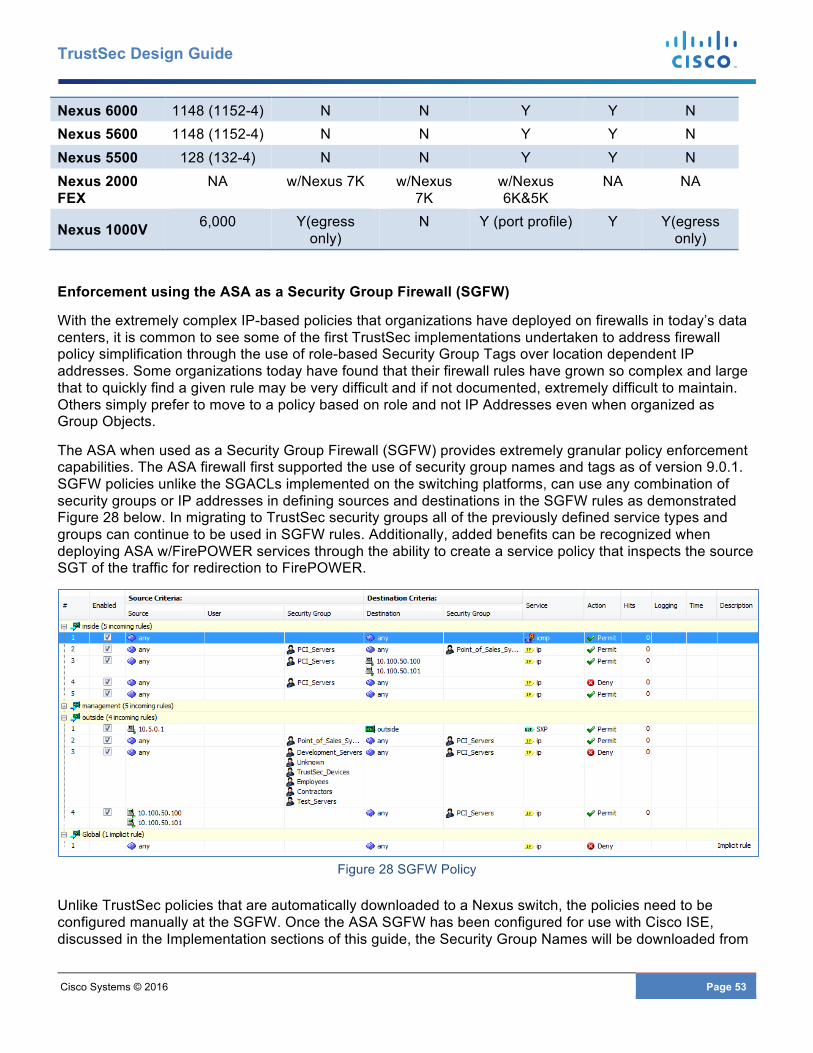
Cisco Systems © 2016 Page 53
TrustSec Design Guide
Nexus 6000 1148 (1152-4) N N Y Y N Nexus 5600 1148 (1152-4) N N Y Y N Nexus 5500 128 (132-4) N N Y Y N Nexus 2000 FEX
NA w/Nexus 7K w/Nexus 7K
w/Nexus 6K&5K
NA NA
Nexus 1000V 6,000 Y(egress only)
N Y (port profile) Y Y(egress only)
Enforcement using the ASA as a Security Group Firewall (SGFW)
With the extremely complex IP-based policies that organizations have deployed on firewalls in today’s data centers, it is common to see some of the first TrustSec implementations undertaken to address firewall policy simplification through the use of role-based Security Group Tags over location dependent IP addresses. Some organizations today have found that their firewall rules have grown so complex and large that to quickly find a given rule may be very difficult and if not documented, extremely difficult to maintain. Others simply prefer to move to a policy based on role and not IP Addresses even when organized as Group Objects.
The ASA when used as a Security Group Firewall (SGFW) provides extremely granular policy enforcement capabilities. The ASA firewall first supported the use of security group names and tags as of version 9.0.1. SGFW policies unlike the SGACLs implemented on the switching platforms, can use any combination of security groups or IP addresses in defining sources and destinations in the SGFW rules as demonstrated Figure 28 below. In migrating to TrustSec security groups all of the previously defined service types and groups can continue to be used in SGFW rules. Additionally, added benefits can be recognized when deploying ASA w/FirePOWER services through the ability to create a service policy that inspects the source SGT of the traffic for redirection to FirePOWER.
Figure 28 SGFW Policy
Unlike TrustSec policies that are automatically downloaded to a Nexus switch, the policies need to be configured manually at the SGFW. Once the ASA SGFW has been configured for use with Cisco ISE, discussed in the Implementation sections of this guide, the Security Group Names will be downloaded from
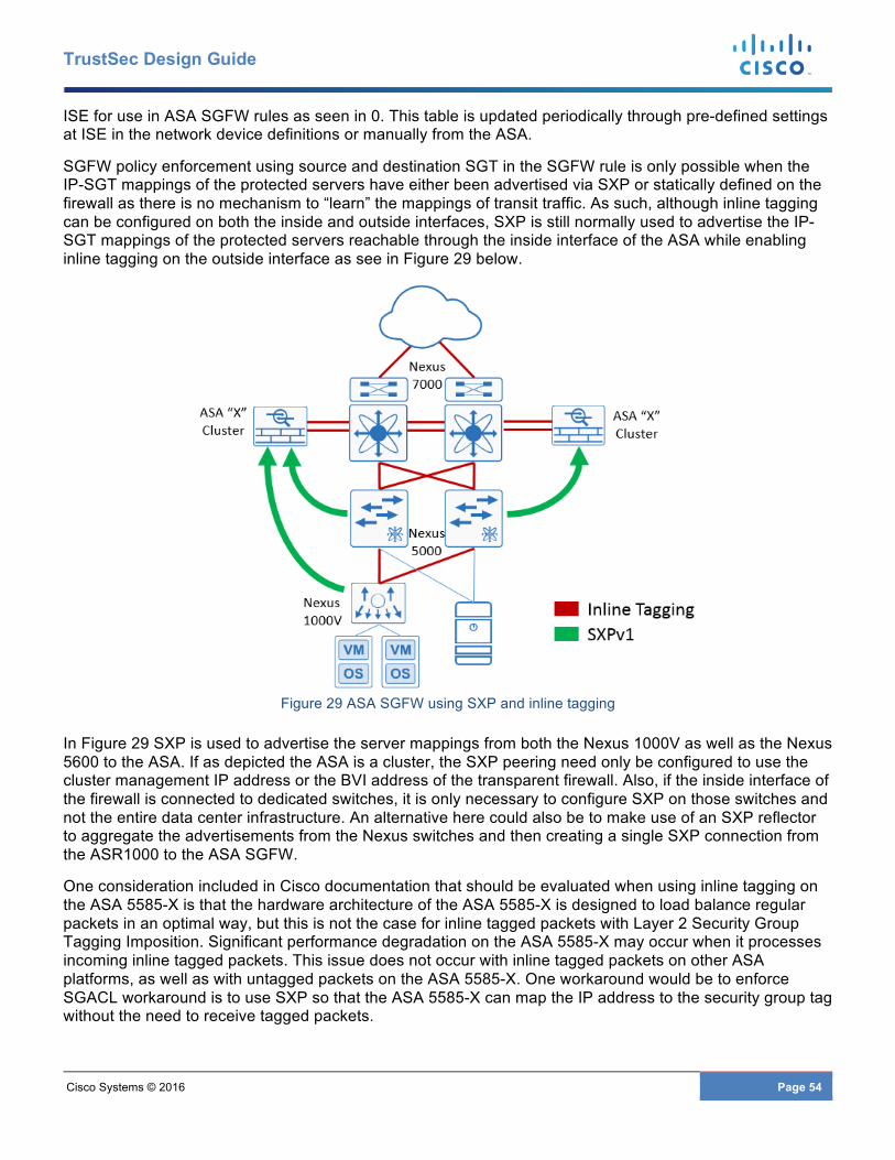
Cisco Systems © 2016 Page 54
TrustSec Design Guide
ISE for use in ASA SGFW rules as seen in 0. This table is updated periodically through pre-defined settings at ISE in the network device definitions or manually from the ASA.
SGFW policy enforcement using source and destination SGT in the SGFW rule is only possible when the IP-SGT mappings of the protected servers have either been advertised via SXP or statically defined on the firewall as there is no mechanism to “learn” the mappings of transit traffic. As such, although inline tagging can be configured on both the inside and outside interfaces, SXP is still normally used to advertise the IP-SGT mappings of the protected servers reachable through the inside interface of the ASA while enabling inline tagging on the outside interface as see in Figure 29 below.
Figure 29 ASA SGFW using SXP and inline tagging
In Figure 29 SXP is used to advertise the server mappings from both the Nexus 1000V as well as the Nexus 5600 to the ASA. If as depicted the ASA is a cluster, the SXP peering need only be configured to use the cluster management IP address or the BVI address of the transparent firewall. Also, if the inside interface of the firewall is connected to dedicated switches, it is only necessary to configure SXP on those switches and not the entire data center infrastructure. An alternative here could also be to make use of an SXP reflector to aggregate the advertisements from the Nexus switches and then creating a single SXP connection from the ASR1000 to the ASA SGFW.
One consideration included in Cisco documentation that should be evaluated when using inline tagging on the ASA 5585-X is that the hardware architecture of the ASA 5585-X is designed to load balance regular packets in an optimal way, but this is not the case for inline tagged packets with Layer 2 Security Group Tagging Imposition. Significant performance degradation on the ASA 5585-X may occur when it processes incoming inline tagged packets. This issue does not occur with inline tagged packets on other ASA platforms, as well as with untagged packets on the ASA 5585-X. One workaround would be to enforce SGACL workaround is to use SXP so that the ASA 5585-X can map the IP address to the security group tag without the need to receive tagged packets.
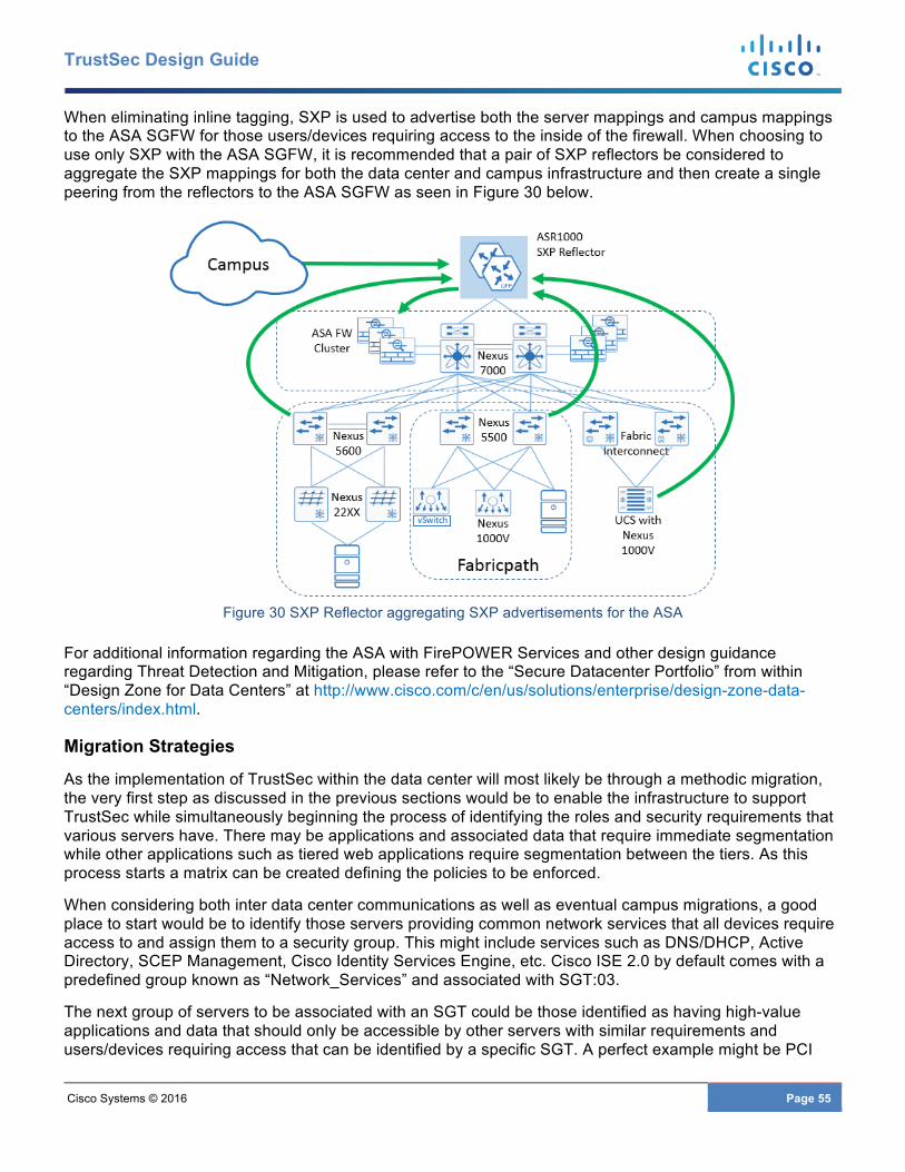
Cisco Systems © 2016 Page 55
TrustSec Design Guide
When eliminating inline tagging, SXP is used to advertise both the server mappings and campus mappings to the ASA SGFW for those users/devices requiring access to the inside of the firewall. When choosing to use only SXP with the ASA SGFW, it is recommended that a pair of SXP reflectors be considered to aggregate the SXP mappings for both the data center and campus infrastructure and then create a single peering from the reflectors to the ASA SGFW as seen in Figure 30 below.
Figure 30 SXP Reflector aggregating SXP advertisements for the ASA
For additional information regarding the ASA with FirePOWER Services and other design guidance regarding Threat Detection and Mitigation, please refer to the “Secure Datacenter Portfolio” from within “Design Zone for Data Centers” at http://www.cisco.com/c/en/us/solutions/enterprise/design-zone-data-centers/index.html.
Migration Strategies
As the implementation of TrustSec within the data center will most likely be through a methodic migration, the very first step as discussed in the previous sections would be to enable the infrastructure to support TrustSec while simultaneously beginning the process of identifying the roles and security requirements that various servers have. There may be applications and associated data that require immediate segmentation while other applications such as tiered web applications require segmentation between the tiers. As this process starts a matrix can be created defining the policies to be enforced.
When considering both inter data center communications as well as eventual campus migrations, a good place to start would be to identify those servers providing common network services that all devices require access to and assign them to a security group. This might include services such as DNS/DHCP, Active Directory, SCEP Management, Cisco Identity Services Engine, etc. Cisco ISE 2.0 by default comes with a predefined group known as “Network_Services” and associated with SGT:03.
The next group of servers to be associated with an SGT could be those identified as having high-value applications and data that should only be accessible by other servers with similar requirements and users/devices requiring access that can be identified by a specific SGT. A perfect example might be PCI
Cisco Systems © 2016 Page 56
TrustSec Design Guide
servers and POS devices requiring access to those processing servers. In doing so, the appropriate SGACLs can be established permitting access between servers and access devices.
Within the data center, this can be easily accomplished through the static classifications discussed in this document. For users or other access devices, however, authentication and dynamic classification although not a requirement, will ultimately provide the most scalable approach. Here RADIUS in conjunction with 802.1x and MAB can be used for authentication while Active Directory and group membership or profiling can be used to assign an SGT. Should static classification for users and devices be the initial approach, it would be possible to simply provide static classifications in the campus distribution using IP-SGT or perhaps Subnet-SGT on Catalyst switching platforms. This way as the untagged user traffic traverses this switching infrastructure, it will tagged upon egress from the device en-route to the destination.
During the initial migration period there will be traffic from users and other devices that have not been classified and hence is untagged (no CMD) or unknown. As this traffic enters network infrastructure enabled for TrustSec at the campus access or data center switches, the Ethernet frames will have a CMD header containing an SGT value of 00 or “unknown”. As this traffic traverses the Catalyst switching infrastructure it will be propagated over the CTS links as SGT:00. In the case of the Nexus infrastructure, after leaving the first Nexus switch it will be remarked to the value configured in the policy static command on that link. This has been discussed in detail in the earlier section entitled “TrustSec Link Policy for Inline Tagging”.
Also in this early migration period, unclassified server traffic will be entering the data center switching infrastructure and depending on how many Nexus switching hops are taken, may arrive at the destination server with either and empty SGT value (00) in the CMD or the TrustSec link tag as previously discussed.
Knowing that this unclassified/untagged traffic will arrive in the data center with either SGT:00 (unknown) or the TrustSec link tag, a policy can be created denying access from “Unknown” or the Ethernet link’s SGT to the protected device. Following such a strategy these unclassified devices have access to everything except those servers that have been classified with an SGT.
Consider also that Cisco ISE has a default policy to “permit IP”. This default policy is used when a cell in the ISE Policy Matrix consisting of a source and destination is left blank. It is therefore not necessary to create any additional policies relative to unknown or the TrustSec link’s SGT. It is for this reason that the SGT value used for TrustSec links should be unique and not the same as that used for Network Devices. As additional servers are classified with an SGT, any traffic with a tag of Unknown or the TrustSec link SGT will have access to those servers until a policy is defined allowing for a gradual migration.
Although the ideal implementation would be to classify all servers prior to deployment this is absolutely not a requirement and can be accomplished on an application by application basis. Several options would be to import lists of server IP addresses and the assigned SGT into ISE for deployment via SXP or static mappings through SSH while another more common approach would be to make use of VLAN to SGT assignments at a Nexus 7000 distribution switch. VLAN-SGT however obviously assumes that servers have been organized in some fashion by the VLAN in which they reside. Port profiles on VM attached to the Nexus 1000V can be modified easily as required to support tagging the various servers.
The single most important takeaway though should be that the migration to TrustSec is NOT an “All or nothing!” undertaking. The best practice is to first identify one or more application(s) that would benefit from the “Software Defined Segmentation” that TrustSec provides and implement it while migrating into an Enterprise policy.
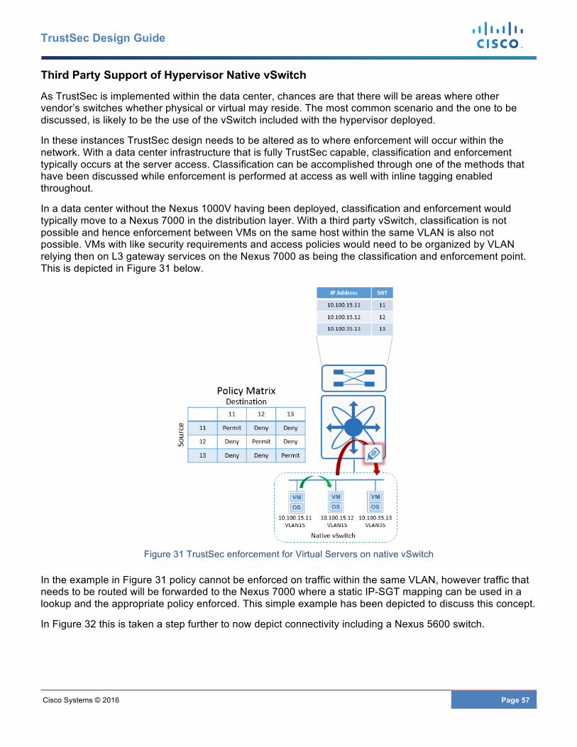
Cisco Systems © 2016 Page 57
TrustSec Design Guide
Third Party Support of Hypervisor Native vSwitch
As TrustSec is implemented within the data center, chances are that there will be areas where other vendor’s switches whether physical or virtual may reside. The most common scenario and the one to be discussed, is likely to be the use of the vSwitch included with the hypervisor deployed.
In these instances TrustSec design needs to be altered as to where enforcement will occur within the network. With a data center infrastructure that is fully TrustSec capable, classification and enforcement typically occurs at the server access. Classification can be accomplished through one of the methods that have been discussed while enforcement is performed at access as well with inline tagging enabled throughout.
In a data center without the Nexus 1000V having been deployed, classification and enforcement would typically move to a Nexus 7000 in the distribution layer. With a third party vSwitch, classification is not possible and hence enforcement between VMs on the same host within the same VLAN is also not possible. VMs with like security requirements and access policies would need to be organized by VLAN relying then on L3 gateway services on the Nexus 7000 as being the classification and enforcement point. This is depicted in Figure 31 below.
Figure 31 TrustSec enforcement for Virtual Servers on native vSwitch
In the example in Figure 31 policy cannot be enforced on traffic within the same VLAN, however traffic that needs to be routed will be forwarded to the Nexus 7000 where a static IP-SGT mapping can be used in a lookup and the appropriate policy enforced. This simple example has been depicted to discuss this concept.
In Figure 32 this is taken a step further to now depict connectivity including a Nexus 5600 switch.
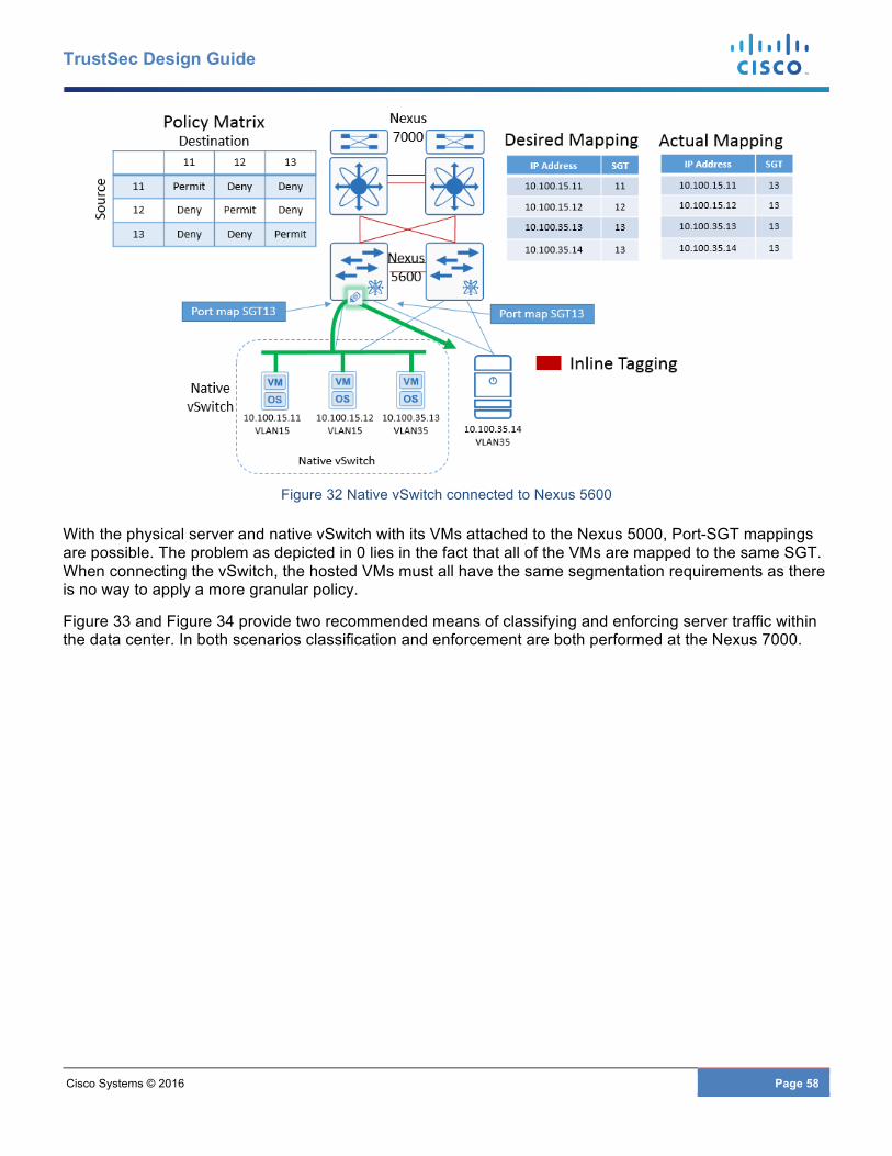
Cisco Systems © 2016 Page 58
TrustSec Design Guide
Figure 32 Native vSwitch connected to Nexus 5600
With the physical server and native vSwitch with its VMs attached to the Nexus 5000, Port-SGT mappings are possible. The problem as depicted in 0 lies in the fact that all of the VMs are mapped to the same SGT. When connecting the vSwitch, the hosted VMs must all have the same segmentation requirements as there is no way to apply a more granular policy.
Figure 33 and Figure 34 provide two recommended means of classifying and enforcing server traffic within the data center. In both scenarios classification and enforcement are both performed at the Nexus 7000.
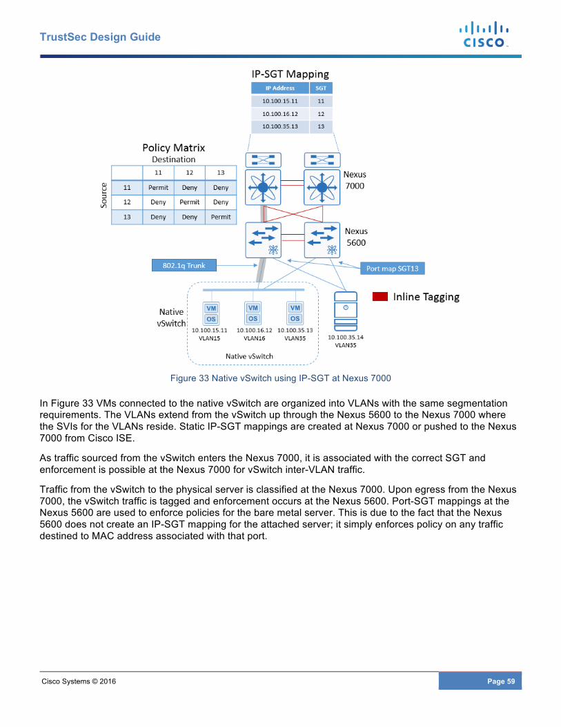
Cisco Systems © 2016 Page 59
TrustSec Design Guide
Figure 33 Native vSwitch using IP-SGT at Nexus 7000
In Figure 33 VMs connected to the native vSwitch are organized into VLANs with the same segmentation requirements. The VLANs extend from the vSwitch up through the Nexus 5600 to the Nexus 7000 where the SVIs for the VLANs reside. Static IP-SGT mappings are created at Nexus 7000 or pushed to the Nexus 7000 from Cisco ISE.
As traffic sourced from the vSwitch enters the Nexus 7000, it is associated with the correct SGT and enforcement is possible at the Nexus 7000 for vSwitch inter-VLAN traffic.
Traffic from the vSwitch to the physical server is classified at the Nexus 7000. Upon egress from the Nexus 7000, the vSwitch traffic is tagged and enforcement occurs at the Nexus 5600. Port-SGT mappings at the Nexus 5600 are used to enforce policies for the bare metal server. This is due to the fact that the Nexus 5600 does not create an IP-SGT mapping for the attached server; it simply enforces policy on any traffic destined to MAC address associated with that port.
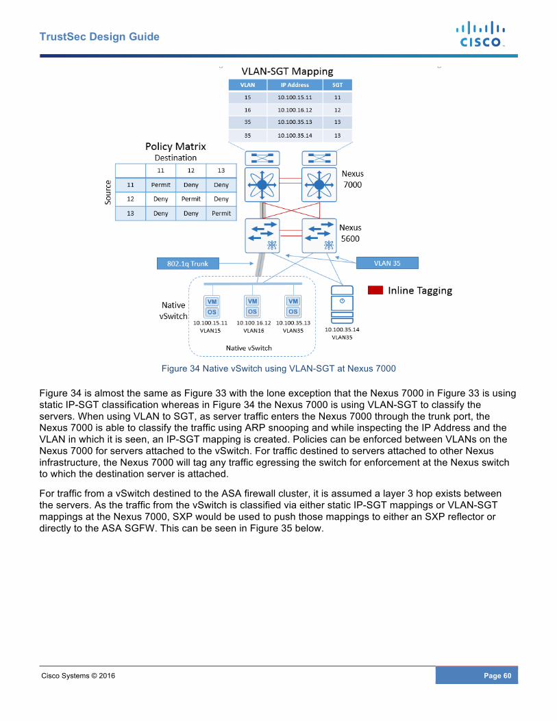
Cisco Systems © 2016 Page 60
TrustSec Design Guide
Figure 34 Native vSwitch using VLAN-SGT at Nexus 7000
Figure 34 is almost the same as Figure 33 with the lone exception that the Nexus 7000 in Figure 33 is using static IP-SGT classification whereas in Figure 34 the Nexus 7000 is using VLAN-SGT to classify the servers. When using VLAN to SGT, as server traffic enters the Nexus 7000 through the trunk port, the Nexus 7000 is able to classify the traffic using ARP snooping and while inspecting the IP Address and the VLAN in which it is seen, an IP-SGT mapping is created. Policies can be enforced between VLANs on the Nexus 7000 for servers attached to the vSwitch. For traffic destined to servers attached to other Nexus infrastructure, the Nexus 7000 will tag any traffic egressing the switch for enforcement at the Nexus switch to which the destination server is attached.
For traffic from a vSwitch destined to the ASA firewall cluster, it is assumed a layer 3 hop exists between the servers. As the traffic from the vSwitch is classified via either static IP-SGT mappings or VLAN-SGT mappings at the Nexus 7000, SXP would be used to push those mappings to either an SXP reflector or directly to the ASA SGFW. This can be seen in Figure 35 below.
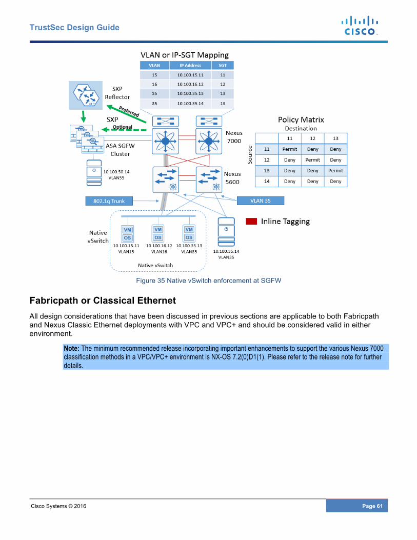
Cisco Systems © 2016 Page 61
TrustSec Design Guide
Figure 35 Native vSwitch enforcement at SGFW
Fabricpath or Classical Ethernet All design considerations that have been discussed in previous sections are applicable to both Fabricpath and Nexus Classic Ethernet deployments with VPC and VPC+ and should be considered valid in either environment.
Note: The minimum recommended release incorporating important enhancements to support the various Nexus 7000 classification methods in a VPC/VPC+ environment is NX-OS 7.2(0)D1(1). Please refer to the release note for further details.
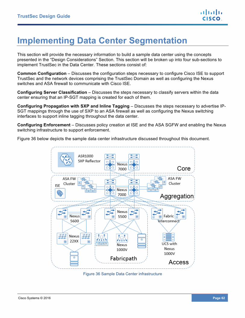
Cisco Systems © 2016 Page 62
TrustSec Design Guide
Implementing Data Center Segmentation This section will provide the necessary information to build a sample data center using the concepts presented in the “Design Considerations” Section. This section will be broken up into four sub-sections to implement TrustSec in the Data Center. These sections consist of:
Common Configuration – Discusses the configuration steps necessary to configure Cisco ISE to support TrustSec and the network devices comprising the TrustSec Domain as well as configuring the Nexus switches and ASA firewall to communicate with Cisco ISE.
Configuring Server Classification – Discusses the steps necessary to classify servers within the data center ensuring that an IP-SGT mapping is created for each of them.
Configuring Propagation with SXP and Inline Tagging – Discusses the steps necessary to advertise IP-SGT mappings through the use of SXP to an ASA firewall as well as configuring the Nexus switching interfaces to support inline tagging throughout the data center.
Configuring Enforcement – Discusses policy creation at ISE and the ASA SGFW and enabling the Nexus switching infrastructure to support enforcement.
Figure 36 below depicts the sample data center infrastructure discussed throughout this document.
Figure 36 Sample Data Center infrastructure
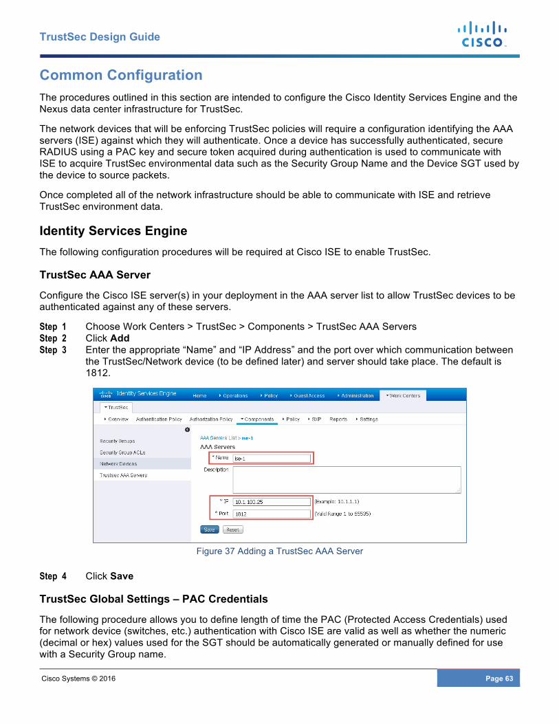
Cisco Systems © 2016 Page 63
TrustSec Design Guide
Common Configuration The procedures outlined in this section are intended to configure the Cisco Identity Services Engine and the Nexus data center infrastructure for TrustSec.
The network devices that will be enforcing TrustSec policies will require a configuration identifying the AAA servers (ISE) against which they will authenticate. Once a device has successfully authenticated, secure RADIUS using a PAC key and secure token acquired during authentication is used to communicate with ISE to acquire TrustSec environmental data such as the Security Group Name and the Device SGT used by the device to source packets.
Once completed all of the network infrastructure should be able to communicate with ISE and retrieve TrustSec environment data.
Identity Services Engine The following configuration procedures will be required at Cisco ISE to enable TrustSec.
TrustSec AAA Server
Configure the Cisco ISE server(s) in your deployment in the AAA server list to allow TrustSec devices to be authenticated against any of these servers.
Step 1 Choose Work Centers > TrustSec > Components > TrustSec AAA Servers Step 2 Click Add Step 3 Enter the appropriate “Name” and “IP Address” and the port over which communication between
the TrustSec/Network device (to be defined later) and server should take place. The default is 1812.
Figure 37 Adding a TrustSec AAA Server
Step 4 Click Save
TrustSec Global Settings – PAC Credentials
The following procedure allows you to define length of time the PAC (Protected Access Credentials) used for network device (switches, etc.) authentication with Cisco ISE are valid as well as whether the numeric (decimal or hex) values used for the SGT should be automatically generated or manually defined for use with a Security Group name.

Cisco Systems © 2016 Page 64
TrustSec Design Guide
Step 1 Choose Work Centers > TrustSec > Settings > General TrustSec Settings. Step 2 Enter the tunnel PAC time (default is 90 days), and proactive PAC update period for refresh.
Note: The tunnel PAC generates a tunnel for the EAP-FAST protocol and is used for Secure RADIUS communications with Network Devices for TrustSec environmental data. A new PAC is generated if the network device re-authenticates for any reason or when the TTL expires.
Step 3 Select whether the SGT value should be automatically generated by the system or manually defined.
Figure 38 Configuring Global TrustSec Settings
Step 4 Click Save
As can be seen in the figure above, all SGT numeric values will be manually defined during the creation of the Security Group name in the next section.
Note: In version 2.0 of Cisco ISE, it is possible to have ISE automatically create new Security Groups and assign a Tag value upon creation of a new Authorization Policy as a matter of convenience. This optional Security Group Creation capability is more relevant to dynamic authentication/authorization of end users/devices and not to data center resources which typically do not make use of authorization policies and hence is not addressed in this document.
Network Device SGT
Network devices comprising the TrustSec domain should be configured with a device SGT. Typically a single SGT is reserved for use as the Device SGT although it may be desirable to have more than one that can be used in conjunction with a user-defined condition such as device type or location. Although optional, it is recommended that all devices be assigned a device SGT and although not mandatory, using SGT:02 as the SGT value. The Security Group Name and SGT value are pre-configured by default in ISE 2.0. Once a network device is configured with a device ID, any traffic sourced from that device will use the defined SGT. This may include communications such as Telnet, SSH, ICMP, and routing updates.
One benefit of the use of a device SGT is that as granular role-based policies using security group tags are defined in the network, the assignment of an SGT to network device will provide an additional level of
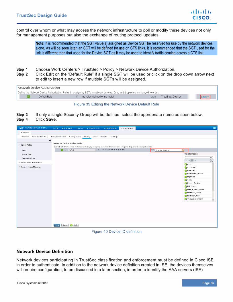
Cisco Systems © 2016 Page 65
TrustSec Design Guide
control over whom or what may access the network infrastructure to poll or modify these devices not only for management purposes but also the exchange of routing protocol updates.
Note: It is recommended that the SGT value(s) assigned as Device SGT be reserved for use by the network devices alone. As will be seen later, an SGT will be defined for use on CTS links. It is recommended that the SGT used for the link is different than that used for the Device SGT as it may be used to identify traffic coming across a CTS link.
Step 1 Choose Work Centers > TrustSec > Policy > Network Device Authorization. Step 2 Click Edit on the “Default Rule” if a single SGT will be used or click on the drop down arrow next
to edit to insert a new row if multiple SGTs will be assigned.
Figure 39 Editing the Network Device Default Rule
Step 3 If only a single Security Group will be defined, select the appropriate name as seen below. Step 4 Click Save.
Figure 40 Device ID definition
Network Device Definition
Network devices participating in TrustSec classification and enforcement must be defined in Cisco ISE in order to authenticate. In addition to the network device definition created in ISE, the devices themselves will require configuration, to be discussed in a later section, in order to identify the AAA servers (ISE)

Cisco Systems © 2016 Page 66
TrustSec Design Guide
against which they will authenticate. This authentication process is known as Network Device Admission Control or NDAC.
Once a device has successfully authenticated, secure RADIUS using a PAC key and secure token acquired during authentication is used to communicate with ISE to acquire TrustSec environmental data such as the Security Group Name and the associated tag, the network device SGT, and role-based policies based on source and destination SGT. Additionally, credentials are defined to allow ISE to access the network devices to install IP-SGT mappings created centrally at ISE.
The following steps must be taken to define the network devices within ISE as depicted in Figure 41:
Step 1 Choose Work Centers > TrustSec > Components > Network Devices and click Add. Step 2 Enter the hostname of the device. This will be the same name as configured later at the network
device using the cts credential command on switches. Step 3 Enter the IP Address of the network device. This must be the same address used to source all
RADIUS communications from the device. Step 4 Optionally, change the Network Device Location or Device Type if a custom location/type has
been previously defined. Here a Network Device Group has been created for “DCSwitch”. This group will be used when configuring static IP-SGT mappings to identify which devices to send these mappings to. static IP-SGT mapping
Step 5 Click the box next to “RADIUS Authentication Settings” and a box will open to configure the “Authentication Settings” information.
Step 6 Configure the RADIUS Shared Secret. This must match that configured on the network device when defining the RADIUS key.
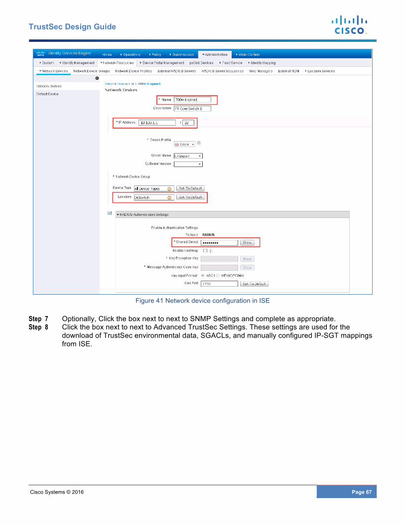
Cisco Systems © 2016 Page 67
TrustSec Design Guide
Figure 41 Network device configuration in ISE
Step 7 Optionally, Click the box next to next to SNMP Settings and complete as appropriate. Step 8 Click the box next to next to Advanced TrustSec Settings. These settings are used for the
download of TrustSec environmental data, SGACLs, and manually configured IP-SGT mappings from ISE.
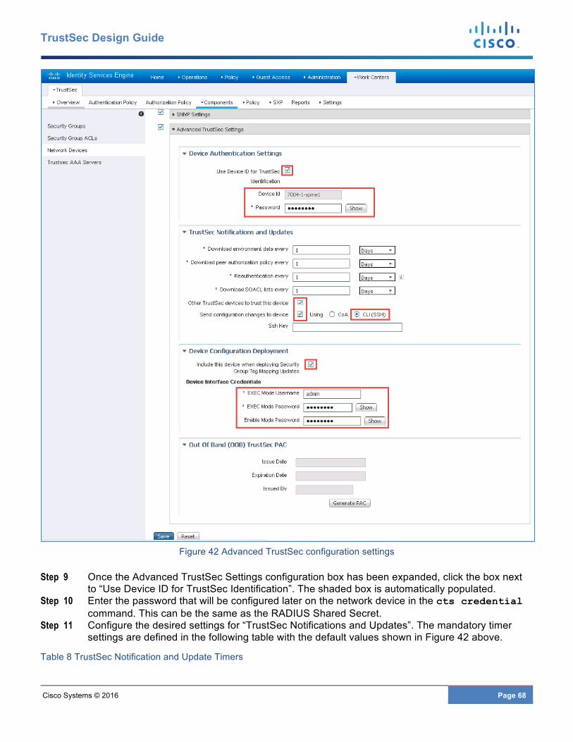
Cisco Systems © 2016 Page 68
TrustSec Design Guide
Figure 42 Advanced TrustSec configuration settings
Step 9 Once the Advanced TrustSec Settings configuration box has been expanded, click the box next to “Use Device ID for TrustSec Identification”. The shaded box is automatically populated.
Step 10 Enter the password that will be configured later on the network device in the cts credential command. This can be the same as the RADIUS Shared Secret.
Step 11 Configure the desired settings for “TrustSec Notifications and Updates”. The mandatory timer settings are defined in the following table with the default values shown in Figure 42 above.
Table 8 TrustSec Notification and Update Timers

Cisco Systems © 2016 Page 69
TrustSec Design Guide
Fields Usage Guidelines
Download Environment Data Every
Specify the expiry time that allows you to configure the time interval in seconds, minutes, hours, weeks, or days between to download the TrustSec device environment information from Cisco ISE. For example, if you enter 60 in seconds, the device would download its environment data from Cisco ISE every minute. The default value is 86,400 seconds or one day. The valid range is from 1 to 24850.
Download Peer Authorization Policy Every
Specify the expiry time that allows you to configure the time interval in seconds, minutes, hours, weeks, or days between to download the peer authorization policy from Cisco ISE. For example, if you enter 60 in seconds, the device would download its peer authorization policy from Cisco ISE every minute. The default value is 86,400 seconds or one day. The valid range is from 1 to 24850.
Reauthentication Every Specify the 802.1X reauthentication period that allows you to configure the time interval in seconds, minutes, hours, weeks or days between for reauthentication. In a network that is configured with the Trustsec solution, after initial authentication, the Trustsec device re authenticates itself against Cisco ISE. For example, if you enter 1000 seconds, the device would authenticate itself against Cisco ISE every 1000 seconds. The default value is 86,400 seconds or one day. The valid range is from 1 to 24850.
Download SGACL Lists Every Specify the expiry time for SGACL lists that allow you to configure the time interval in seconds, minutes, hours, weeks or days between to download SGACLs from Cisco ISE. For example, if you enter 3600 seconds, the network device obtains the SGACL lists from Cisco ISE every 3600 seconds. The default value is 86,400 seconds or one day. The valid range is from 1 to 24850.
Other Trustsec Devices to Trust This Device (Trustsec Trusted)
Check this check box if you want all the peer devices to trust this Trustsec device. If you uncheck this check box, the peer devices do not trust this device, and all packets that arrive from this device will be colored or tagged accordingly.
Note: These settings determine the frequency of the automatic TrustSec updates to the network device. It is recommended that aggressive timers only be used after careful testing. As such the values depicted in 0have been left at the default value of one day. In addition to these periodic updates, it is possible to manually refresh the environment
Cisco Systems © 2016 Page 70
TrustSec Design Guide
data containing Security Group names/Tags, Network Device SGT, and AAA Server information as well as SGT Egress Policy (SGACL) both from within ISE as well as the network device.
Step 12 To notify TrustSec devices of policy or configuration changes, Cisco ISE will use a CoA (Change of Authorization) request or login to the device via SSH to download the updated information. In order to use CoA on Nexus 7000 it must be running NX-OS 7.2(0)D1(1) or later. The Nexus 6000, 5600, 5500 and 1000V do not support CoA. For these switches click the box next to “Send configuration changes to device” and select the radio button for “CLI (SSH)”. For the Nexus 7000, either CLI or C0A can be used. ISE will connect to the network device via an SSHv2 Tunnel and sends a command that triggers a refresh of the TrustSec policy matrix.
Step 13 Check the box for “Include this device when deploying Security Group Tag Mapping updates” whereupon after adding manual IP to SGT mappings at ISE, and deploying those mappings, this network device will receive these updates.
Step 14 Provide network device access credential such that ISE can access the device to add the IP-SGT mappings or if CLI is selected as a means by which policy updates will be initiated from Step 12 above.
Step 15 Click Save.
Nexus Switching Radius Configuration In order to authenticate, the network device(s) will require a configuration identifying the AAA servers (ISE) against which they will authenticate. Once a device has successfully authenticated, secure RADIUS using a PAC key and secure token acquired during authentication is used to communicate with ISE to acquire TrustSec environmental data such as the Security Group Name and the numeric value associated with the tag, an optional SGT used by the device to source packets, and SGT/IP mappings that have been created at ISE. Additionally, policies based on SGTs in the form of SGACLs created at ISE are pushed out to those Nexus switches capable of enforcing them.
The following commands provide an example for first enabling the dot1x and cts features and then defining the radius configuration identifying the Cisco ISE (AAA) server.
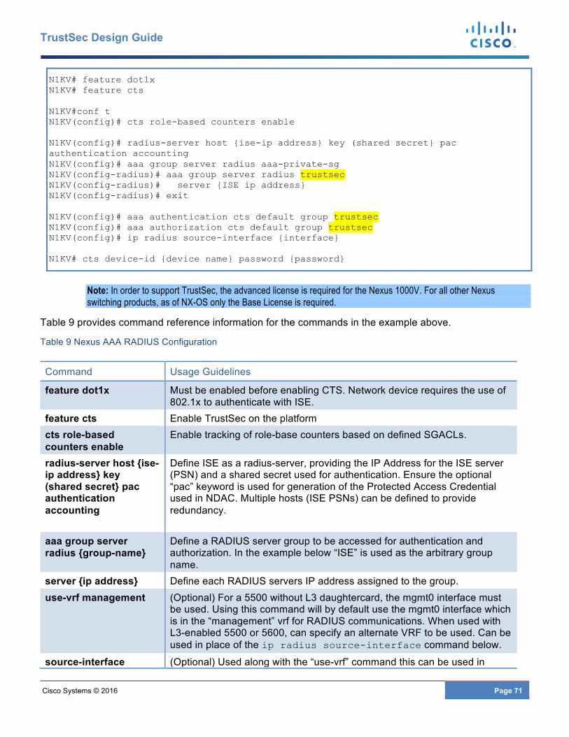
Cisco Systems © 2016 Page 71
TrustSec Design Guide
N1KV# feature dot1x N1KV# feature cts N1KV#conf t N1KV(config)# cts role-based counters enable N1KV(config)# radius-server host {ise-ip address} key (shared secret} pac authentication accounting N1KV(config)# aaa group server radius aaa-private-sg N1KV(config-radius)# aaa group server radius trustsec N1KV(config-radius)# server {ISE ip address} N1KV(config-radius)# exit N1KV(config)# aaa authentication cts default group trustsec N1KV(config)# aaa authorization cts default group trustsec N1KV(config)# ip radius source-interface {interface} N1KV# cts device-id {device name} password {password}
Note: In order to support TrustSec, the advanced license is required for the Nexus 1000V. For all other Nexus switching products, as of NX-OS only the Base License is required.
Table 9 provides command reference information for the commands in the example above.
Table 9 Nexus AAA RADIUS Configuration
Command Usage Guidelines
feature dot1x Must be enabled before enabling CTS. Network device requires the use of 802.1x to authenticate with ISE.
feature cts Enable TrustSec on the platform cts role-based counters enable
Enable tracking of role-base counters based on defined SGACLs.
radius-server host {ise-ip address} key (shared secret} pac authentication accounting
Define ISE as a radius-server, providing the IP Address for the ISE server (PSN) and a shared secret used for authentication. Ensure the optional “pac” keyword is used for generation of the Protected Access Credential used in NDAC. Multiple hosts (ISE PSNs) can be defined to provide redundancy.
aaa group server radius {group-name}
Define a RADIUS server group to be accessed for authentication and authorization. In the example below “ISE” is used as the arbitrary group name.
server {ip address} Define each RADIUS servers IP address assigned to the group. use-vrf management (Optional) For a 5500 without L3 daughtercard, the mgmt0 interface must
be used. Using this command will by default use the mgmt0 interface which is in the “management” vrf for RADIUS communications. When used with L3-enabled 5500 or 5600, can specify an alternate VRF to be used. Can be used in place of the ip radius source-interface command below.
source-interface (Optional) Used along with the “use-vrf” command this can be used in
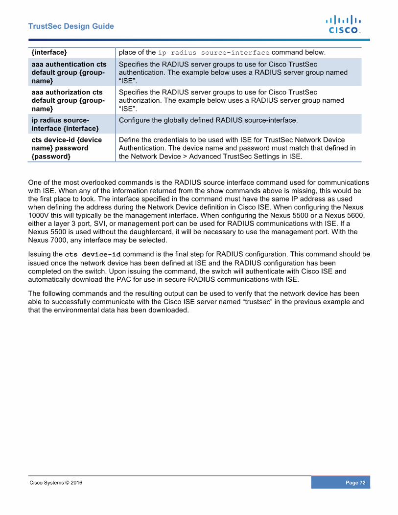
Cisco Systems © 2016 Page 72
TrustSec Design Guide
{interface} place of the ip radius source-interface command below.
aaa authentication cts default group {group-name}
Specifies the RADIUS server groups to use for Cisco TrustSec authentication. The example below uses a RADIUS server group named “ISE”.
aaa authorization cts default group {group-name}
Specifies the RADIUS server groups to use for Cisco TrustSec authorization. The example below uses a RADIUS server group named “ISE”.
ip radius source-interface {interface}
Configure the globally defined RADIUS source-interface.
cts device-id {device name} password {password}
Define the credentials to be used with ISE for TrustSec Network Device Authentication. The device name and password must match that defined in the Network Device > Advanced TrustSec Settings in ISE.
One of the most overlooked commands is the RADIUS source interface command used for communications with ISE. When any of the information returned from the show commands above is missing, this would be the first place to look. The interface specified in the command must have the same IP address as used when defining the address during the Network Device definition in Cisco ISE. When configuring the Nexus 1000V this will typically be the management interface. When configuring the Nexus 5500 or a Nexus 5600, either a layer 3 port, SVI, or management port can be used for RADIUS communications with ISE. If a Nexus 5500 is used without the daughtercard, it will be necessary to use the management port. With the Nexus 7000, any interface may be selected.
Issuing the cts device-id command is the final step for RADIUS configuration. This command should be issued once the network device has been defined at ISE and the RADIUS configuration has been completed on the switch. Upon issuing the command, the switch will authenticate with Cisco ISE and automatically download the PAC for use in secure RADIUS communications with ISE.
The following commands and the resulting output can be used to verify that the network device has been able to successfully communicate with the Cisco ISE server named “trustsec” in the previous example and that the environmental data has been downloaded.
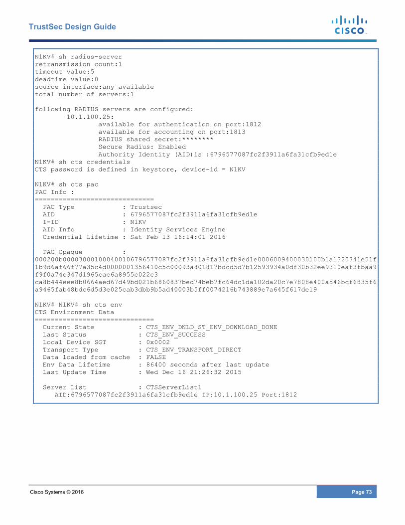
Cisco Systems © 2016 Page 73
TrustSec Design Guide
N1KV# sh radius-server retransmission count:1 timeout value:5 deadtime value:0 source interface:any available total number of servers:1 following RADIUS servers are configured: 10.1.100.25: available for authentication on port:1812 available for accounting on port:1813 RADIUS shared secret:******** Secure Radius: Enabled Authority Identity (AID)is :6796577087fc2f3911a6fa31cfb9ed1e N1KV# sh cts credentials CTS password is defined in keystore, device-id = N1KV N1KV# sh cts pac PAC Info : ============================== PAC Type : Trustsec AID : 6796577087fc2f3911a6fa31cfb9ed1e I-ID : N1KV AID Info : Identity Services Engine Credential Lifetime : Sat Feb 13 16:14:01 2016 PAC Opaque : 000200b000030001000400106796577087fc2f3911a6fa31cfb9ed1e0006009400030100b1a1320341e51f1b9d6af66f77a35c4d0000001356410c5c00093a801817bdcd5d7b12593934a0df30b32ee9310eaf3fbaa9f9f0a74c347d1965cae6a8955c022c3 ca8b444eee8b0664aed67d49bd021b6860837bed74beb7fc64dc1da102da20c7e7808e400a546bcf6835f6a9465fab48bdc6d5d3e025cab3dbb9b5ad40003b5ff0074216b743889e7a645f617de19 N1KV# N1KV# sh cts env CTS Environment Data ============================== Current State : CTS_ENV_DNLD_ST_ENV_DOWNLOAD_DONE Last Status : CTS_ENV_SUCCESS Local Device SGT : 0x0002 Transport Type : CTS_ENV_TRANSPORT_DIRECT Data loaded from cache : FALSE Env Data Lifetime : 86400 seconds after last update Last Update Time : Wed Dec 16 21:26:32 2015 Server List : CTSServerList1 AID:6796577087fc2f3911a6fa31cfb9ed1e IP:10.1.100.25 Port:1812
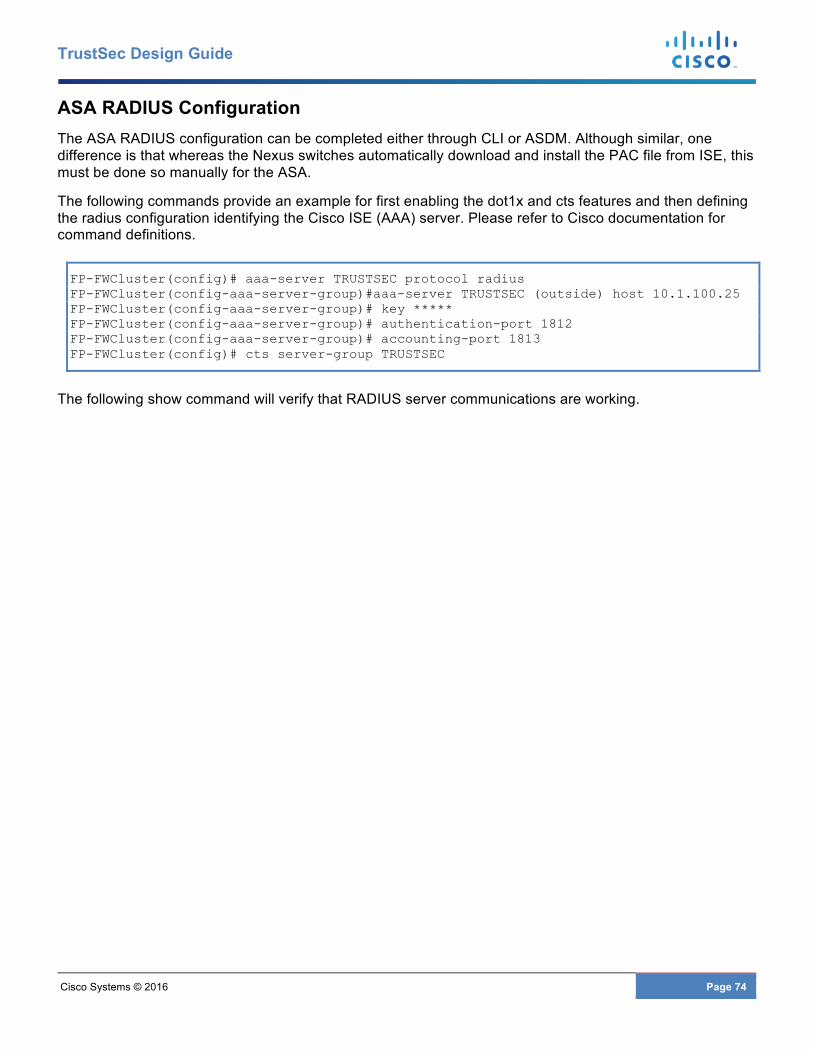
Cisco Systems © 2016 Page 74
TrustSec Design Guide
ASA RADIUS Configuration The ASA RADIUS configuration can be completed either through CLI or ASDM. Although similar, one difference is that whereas the Nexus switches automatically download and install the PAC file from ISE, this must be done so manually for the ASA.
The following commands provide an example for first enabling the dot1x and cts features and then defining the radius configuration identifying the Cisco ISE (AAA) server. Please refer to Cisco documentation for command definitions.
FP-FWCluster(config)# aaa-server TRUSTSEC protocol radius FP-FWCluster(config-aaa-server-group)#aaa-server TRUSTSEC (outside) host 10.1.100.25 FP-FWCluster(config-aaa-server-group)# key ***** FP-FWCluster(config-aaa-server-group)# authentication-port 1812 FP-FWCluster(config-aaa-server-group)# accounting-port 1813 FP-FWCluster(config)# cts server-group TRUSTSEC
The following show command will verify that RADIUS server communications are working.
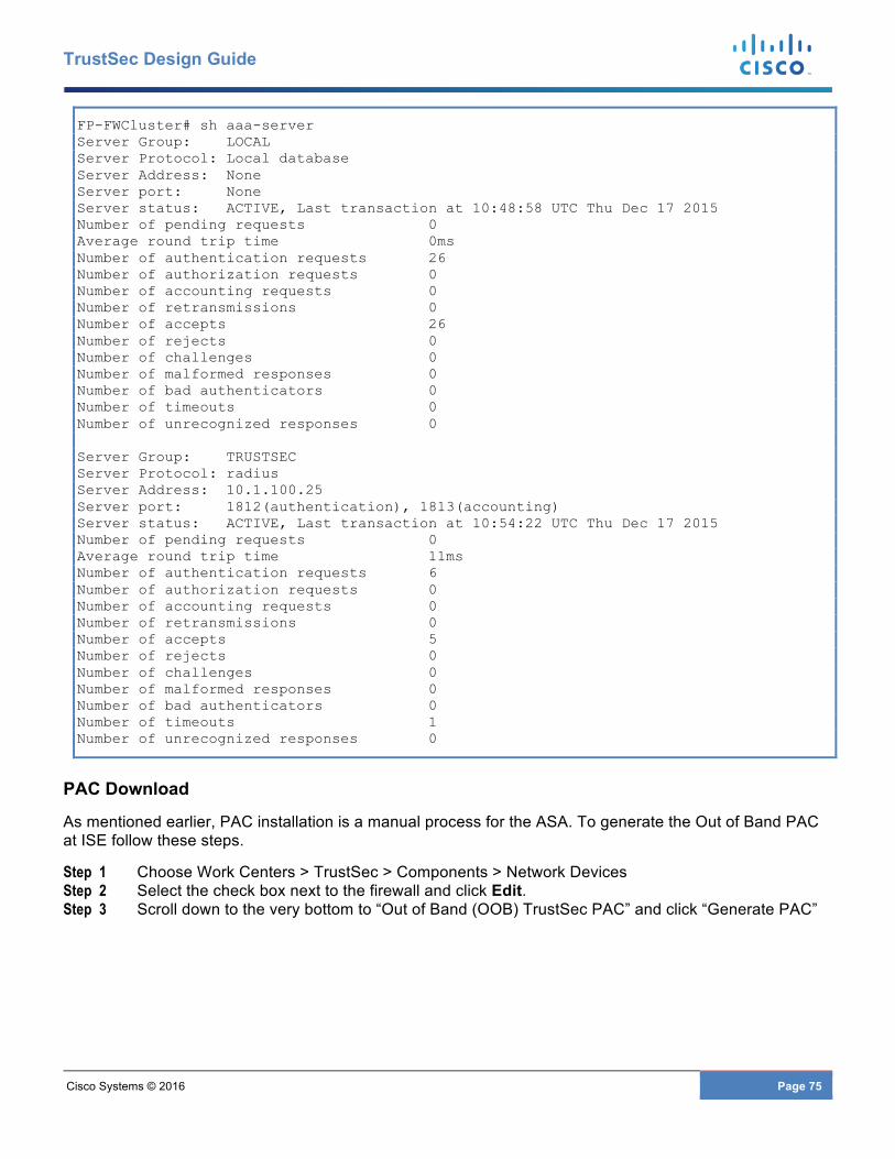
Cisco Systems © 2016 Page 75
TrustSec Design Guide
FP-FWCluster# sh aaa-server Server Group: LOCAL Server Protocol: Local database Server Address: None Server port: None Server status: ACTIVE, Last transaction at 10:48:58 UTC Thu Dec 17 2015 Number of pending requests 0 Average round trip time 0ms Number of authentication requests 26 Number of authorization requests 0 Number of accounting requests 0 Number of retransmissions 0 Number of accepts 26 Number of rejects 0 Number of challenges 0 Number of malformed responses 0 Number of bad authenticators 0 Number of timeouts 0 Number of unrecognized responses 0 Server Group: TRUSTSEC Server Protocol: radius Server Address: 10.1.100.25 Server port: 1812(authentication), 1813(accounting) Server status: ACTIVE, Last transaction at 10:54:22 UTC Thu Dec 17 2015 Number of pending requests 0 Average round trip time 11ms Number of authentication requests 6 Number of authorization requests 0 Number of accounting requests 0 Number of retransmissions 0 Number of accepts 5 Number of rejects 0 Number of challenges 0 Number of malformed responses 0 Number of bad authenticators 0 Number of timeouts 1 Number of unrecognized responses 0
PAC Download
As mentioned earlier, PAC installation is a manual process for the ASA. To generate the Out of Band PAC at ISE follow these steps.
Step 1 Choose Work Centers > TrustSec > Components > Network Devices Step 2 Select the check box next to the firewall and click Edit. Step 3 Scroll down to the very bottom to “Out of Band (OOB) TrustSec PAC” and click “Generate PAC”
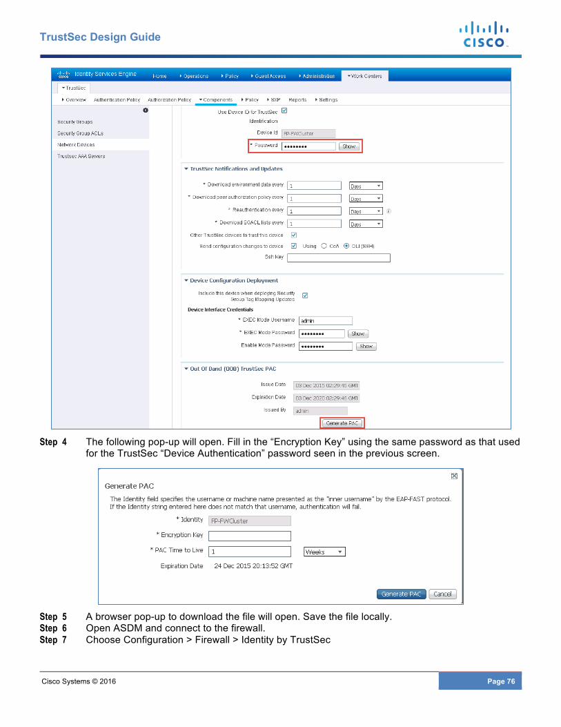
Cisco Systems © 2016 Page 76
TrustSec Design Guide
Step 4 The following pop-up will open. Fill in the “Encryption Key” using the same password as that used
for the TrustSec “Device Authentication” password seen in the previous screen.
Step 5 A browser pop-up to download the file will open. Save the file locally. Step 6 Open ASDM and connect to the firewall. Step 7 Choose Configuration > Firewall > Identity by TrustSec
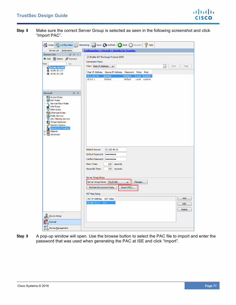
Cisco Systems © 2016 Page 77
TrustSec Design Guide
Step 8 Make sure the correct Server Group is selected as seen in the following screenshot and click “Import PAC”.
Step 9 A pop-up window will open. Use the browse button to select the PAC file to import and enter the
password that was used when generating the PAC at ISE and click “Import”.
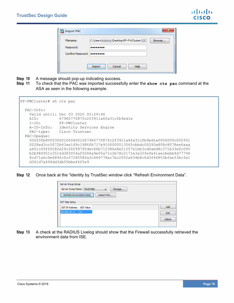
Cisco Systems © 2016 Page 78
TrustSec Design Guide
Step 10 A message should pop-up indicating success. Step 11 To check that the PAC was imported successfully enter the show cts pac command at the
ASA as seen in the following example.
FP-FWCluster# sh cts pac PAC-Info: Valid until: Dec 03 2020 02:29:46 AID: 6796577087fc2f3911a6fa31cfb9ed1e I-ID: FP-FWCluster A-ID-Info: Identity Services Engine PAC-type: Cisco Trustsec PAC-Opaque: 000200b800030001000400106796577087fc2f3911a6fa31cfb9ed1e0006009c000301 0028ad3cc5072b43ae149c1986fb717e9100000013565cbbdc00093a808c8078ee6aaa a401c69ff0282e29c26f9979fdec66b712386a8e21257e1bb3cd0abd8c371b33e0c095 b2b984951c2516d383054af5044a9e05a71c2b78c2171e3a32fe9a41aecbebb4d77794 8cd71a6c9e689fc0cf728558fa2c669778ac7bc2932a634b8c0d3f46853bfee33bc3a1 d361d7a494dd3db05bbe44f5e9
Step 12 Once back at the “Identity by TrustSec window click “Refresh Environment Data”.
Step 13 A check at the RADIUS Livelog should show that the Firewall successfully retrieved the
environment data from ISE.
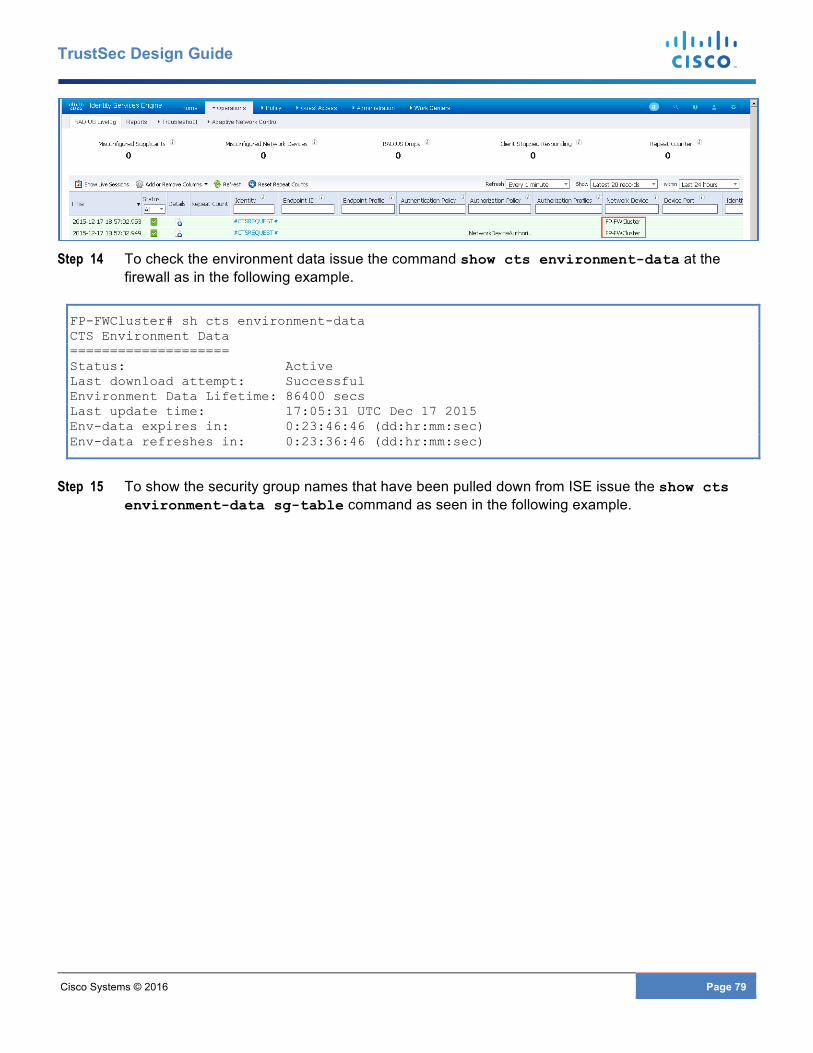
Cisco Systems © 2016 Page 79
TrustSec Design Guide
Step 14 To check the environment data issue the command show cts environment-data at the
firewall as in the following example.
FP-FWCluster# sh cts environment-data CTS Environment Data ==================== Status: Active Last download attempt: Successful Environment Data Lifetime: 86400 secs Last update time: 17:05:31 UTC Dec 17 2015 Env-data expires in: 0:23:46:46 (dd:hr:mm:sec) Env-data refreshes in: 0:23:36:46 (dd:hr:mm:sec)
Step 15 To show the security group names that have been pulled down from ISE issue the show cts environment-data sg-table command as seen in the following example.
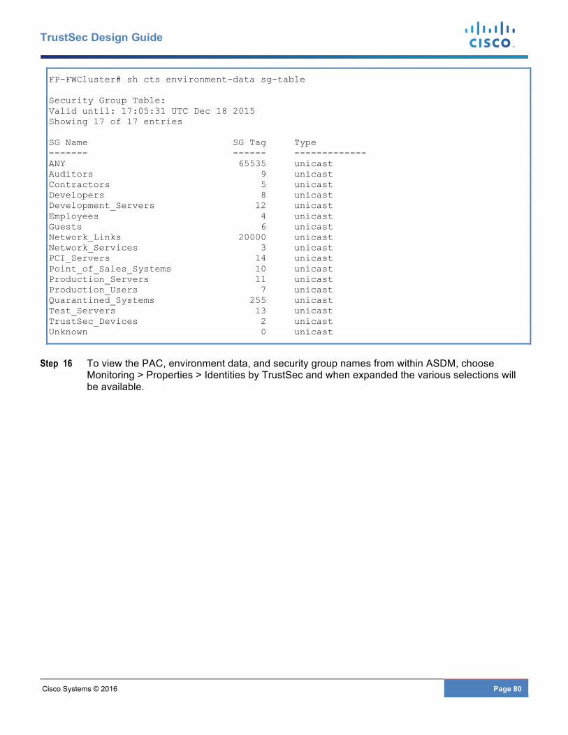
Cisco Systems © 2016 Page 80
TrustSec Design Guide
FP-FWCluster# sh cts environment-data sg-table Security Group Table: Valid until: 17:05:31 UTC Dec 18 2015 Showing 17 of 17 entries SG Name SG Tag Type ------- ------ ------------- ANY 65535 unicast Auditors 9 unicast Contractors 5 unicast Developers 8 unicast Development_Servers 12 unicast Employees 4 unicast Guests 6 unicast Network_Links 20000 unicast Network_Services 3 unicast PCI_Servers 14 unicast Point_of_Sales_Systems 10 unicast Production_Servers 11 unicast Production_Users 7 unicast Quarantined_Systems 255 unicast Test_Servers 13 unicast TrustSec_Devices 2 unicast Unknown 0 unicast
Step 16 To view the PAC, environment data, and security group names from within ASDM, choose Monitoring > Properties > Identities by TrustSec and when expanded the various selections will be available.
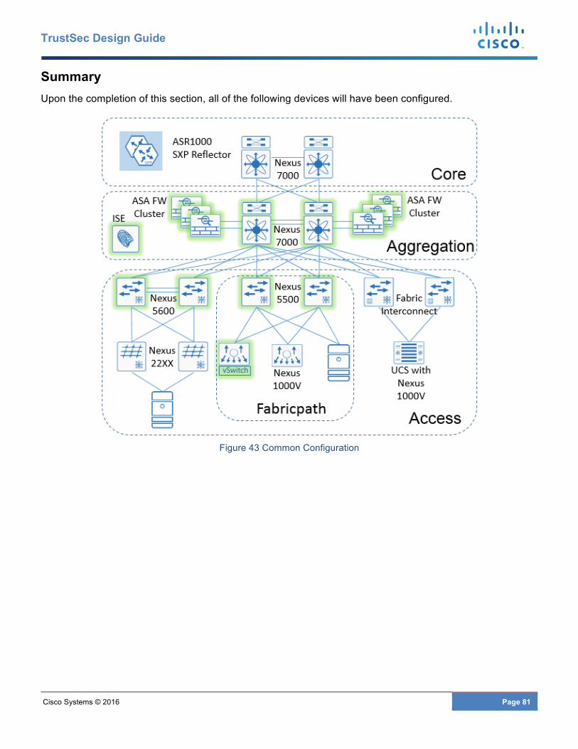
Cisco Systems © 2016 Page 81
TrustSec Design Guide
Summary Upon the completion of this section, all of the following devices will have been configured.
Figure 43 Common Configuration
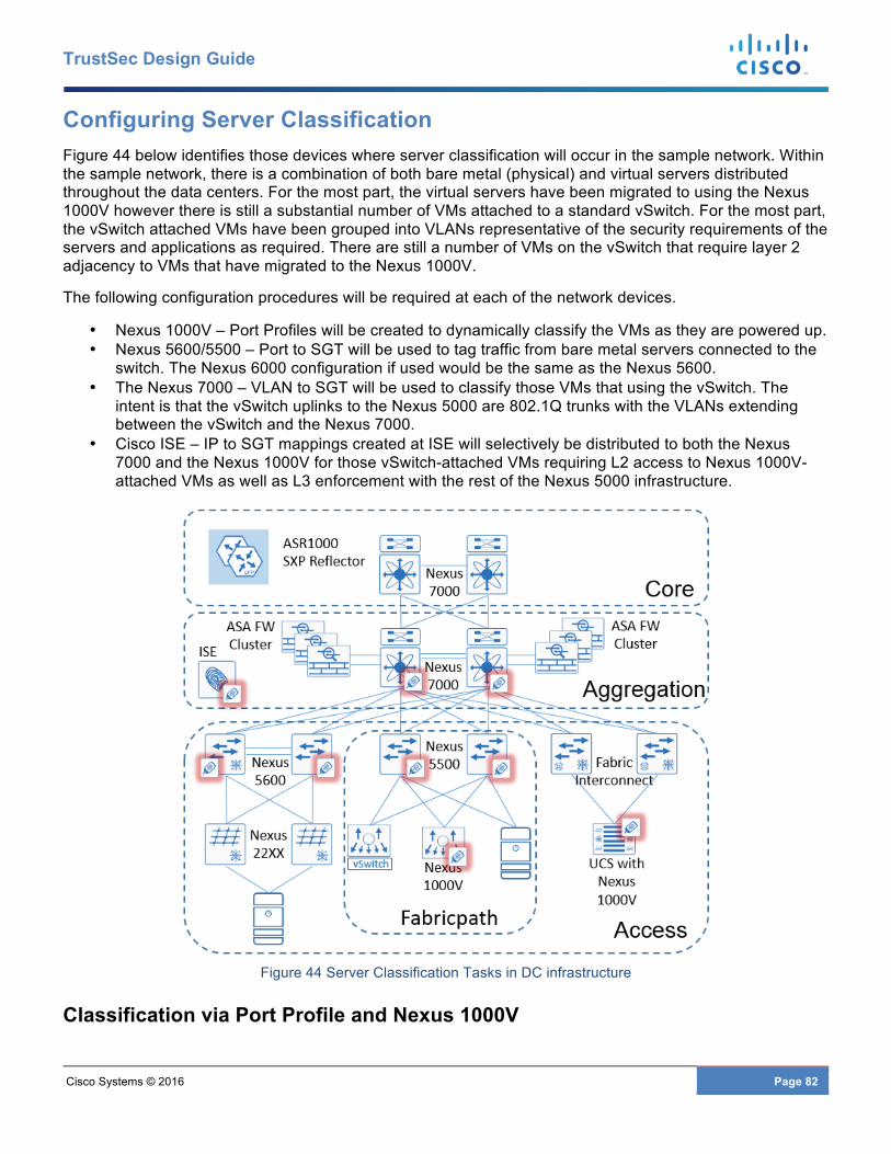
Cisco Systems © 2016 Page 82
TrustSec Design Guide
Configuring Server Classification Figure 44 below identifies those devices where server classification will occur in the sample network. Within the sample network, there is a combination of both bare metal (physical) and virtual servers distributed throughout the data centers. For the most part, the virtual servers have been migrated to using the Nexus 1000V however there is still a substantial number of VMs attached to a standard vSwitch. For the most part, the vSwitch attached VMs have been grouped into VLANs representative of the security requirements of the servers and applications as required. There are still a number of VMs on the vSwitch that require layer 2 adjacency to VMs that have migrated to the Nexus 1000V.
The following configuration procedures will be required at each of the network devices.
• Nexus 1000V – Port Profiles will be created to dynamically classify the VMs as they are powered up. • Nexus 5600/5500 – Port to SGT will be used to tag traffic from bare metal servers connected to the
switch. The Nexus 6000 configuration if used would be the same as the Nexus 5600. • The Nexus 7000 – VLAN to SGT will be used to classify those VMs that using the vSwitch. The
intent is that the vSwitch uplinks to the Nexus 5000 are 802.1Q trunks with the VLANs extending between the vSwitch and the Nexus 7000.
• Cisco ISE – IP to SGT mappings created at ISE will selectively be distributed to both the Nexus 7000 and the Nexus 1000V for those vSwitch-attached VMs requiring L2 access to Nexus 1000V-attached VMs as well as L3 enforcement with the rest of the Nexus 5000 infrastructure.
Figure 44 Server Classification Tasks in DC infrastructure
Classification via Port Profile and Nexus 1000V

Cisco Systems © 2016 Page 83
TrustSec Design Guide
Classification on the Nexus 1000V is performed by configuring the port profile that is assigned to the virtual machine the same as a VMware port group would be used. This port profile is then used as the virtual machine powers up to create a vEthernet port which is a logical interface on the Nexus 1000V.
As the virtual server is powered on, Device Tracking on the Nexus 1000V is used to learn the IP address of the VM through ARP messages and IP traffic. This information is then used by the Nexus 1000V to create the IP-SGT mapping derived from the port profile. Unlike Port-SGT mapping on the Nexus 6000, 5600, and 5500 switches which do not create an IP-SGT mapping on the switch, the IP-SGT mappings created as a result of the port profile can be advertised via SXP. In order to enable device tracking and check that it is running, please see the following example.
N1KV(config)# cts device tracking N1KV# sh cts device tracking Enabled
An example of a port profile definition can be seen in the following example. In this example, the virtual machine will be assigned an SGT of 11 (0xb hex).
N1KV(config)#port-profile type vethernet Prod_Serv1_FP_VL10 N1KV(config-port-prof)# switchport mode access N1KV(config-port-prof)# switchport access vlan 10 N1KV(config-port-prof)# cts manual N1KV(config-port-prof-cts-manual) policy static sgt 0xb N1KV(config-port-prof-cts-manual) role-based enforcement N1KV(config-port-prof-cts-manual) exit N1KV(config-port-prof)# no shutdown N1KV(config-port-prof)# state enabled N1KV(config-port-prof)# vmware port-group N1KV(config-port-prof)# exit N1KV(config)#
Command Usage Guidelines
port-profile type vethernet {profile name} Create a vethernet port profile for use as vnic for VM attached to Nexus 1000V
switchport mode access Port profile defined as an access switch port.. switchport access vlan 10 Port profile VLAN assignment. cts manual Enable TrustSec on the interface. policy static sgt 0xb Define the SGT assigned to the port profile
specified as a hex value. For an access port the “trusted” keyword should not be used.
role-based enforcement Enables Cisco TrustSec SGACL policy enforcement on the port profile.
exit Exit the cts configuration mode. It is highly recommended that configuration mode be exited properly.
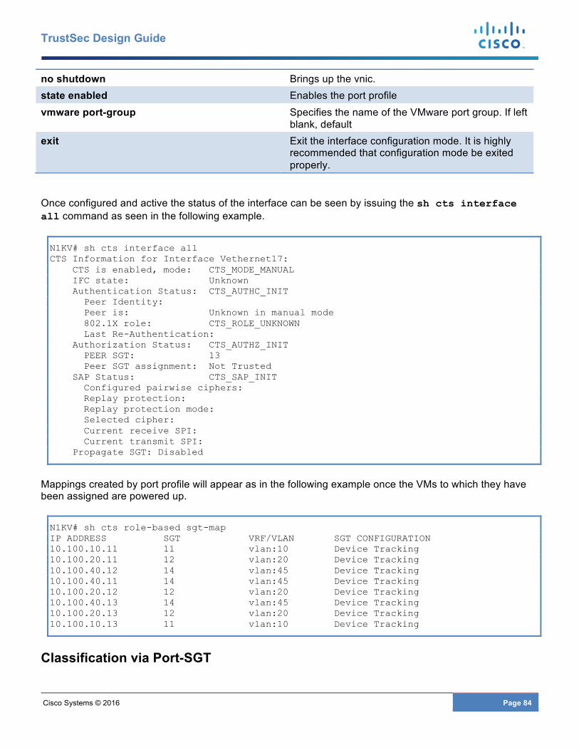
Cisco Systems © 2016 Page 84
TrustSec Design Guide
no shutdown Brings up the vnic. state enabled Enables the port profile vmware port-group Specifies the name of the VMware port group. If left
blank, default exit Exit the interface configuration mode. It is highly
recommended that configuration mode be exited properly.
Once configured and active the status of the interface can be seen by issuing the sh cts interface all command as seen in the following example.
N1KV# sh cts interface all CTS Information for Interface Vethernet17: CTS is enabled, mode: CTS_MODE_MANUAL IFC state: Unknown Authentication Status: CTS_AUTHC_INIT Peer Identity: Peer is: Unknown in manual mode 802.1X role: CTS_ROLE_UNKNOWN Last Re-Authentication: Authorization Status: CTS_AUTHZ_INIT PEER SGT: 13 Peer SGT assignment: Not Trusted SAP Status: CTS_SAP_INIT Configured pairwise ciphers: Replay protection: Replay protection mode: Selected cipher: Current receive SPI: Current transmit SPI: Propagate SGT: Disabled
Mappings created by port profile will appear as in the following example once the VMs to which they have been assigned are powered up.
N1KV# sh cts role-based sgt-map IP ADDRESS SGT VRF/VLAN SGT CONFIGURATION 10.100.10.11 11 vlan:10 Device Tracking 10.100.20.11 12 vlan:20 Device Tracking 10.100.40.12 14 vlan:45 Device Tracking 10.100.40.11 14 vlan:45 Device Tracking 10.100.20.12 12 vlan:20 Device Tracking 10.100.40.13 14 vlan:45 Device Tracking 10.100.20.13 12 vlan:20 Device Tracking 10.100.10.13 11 vlan:10 Device Tracking
Classification via Port-SGT

Cisco Systems © 2016 Page 85
TrustSec Design Guide
Nexus 6000/5600/5500
The following example depicts the commands necessary to configure a Nexus 6K/5K access port for connection to a server. Recall that this will not create an IP-SGT mapping entry but merely appends the defined SGT to any traffic from that port. Hence with port to SGT on the Nexus 6000/5000 show cts role-based sgt-map will provide no output.
Note: When enabling TrustSec on an interface through the use of the cts manual command and subsequently entering the policy static command, it is imperative that the cts manual config mode be exited through the use of the exit command. The interface must then be shut down and brought back up to enable CTS.
5548-3# sh run int e1/5 5548-1(config)# interface Ethernet1/5 5548-1(config-if)# switchport access vlan 15 5548-1(config-if)# spanning-tree port type edge 5548-1(config-if)# cts manual 5548-1(config-if-cts-manual)# no propagate-sgt 5548-1(config-if-cts-manual)# policy static sgt 0xb 5548-1(config-if-cts-manual)# exit 5548-1(config-if)# shutdown 5548-1(config-if)# no shutdown
Command Usage Guidelines
interface EthernetX/X Enter interface configuration mode. switchport access vlan 10 Define the VLAN to which the port is assigned. spanning-tree port type edge (Optional) Define the port as an Edge Port for quick transition to
forwarding state; same as Cisco proprietary PortFast. cts manual Enable TrustSec in manual mode on the interface.
no propagate-sgt Disable SGT propagation on the interface as this is a access port
to a server. Note: It is mandatory that this be entered on any port to a server or a non-Cisco vSwitch port incapable of SGT tagging otherwise the device(s) will be unable to communicate.
policy static sgt 11 Define the SGT that the device or devices (in the case of a non-Cisco vSwitch port) will be assigned by ythe Nexus 5500/5600. The value can be specified in decimal as shown here or in hex; ie 0xb. When showing the config it will always display in hex.
exit Exit the interface configuration mode. It is highly recommended that CTS configuration mode be exited properly.
shut/no shut It is highly recommended that the port be shut down and brought back up after enabling CTS on the interface.
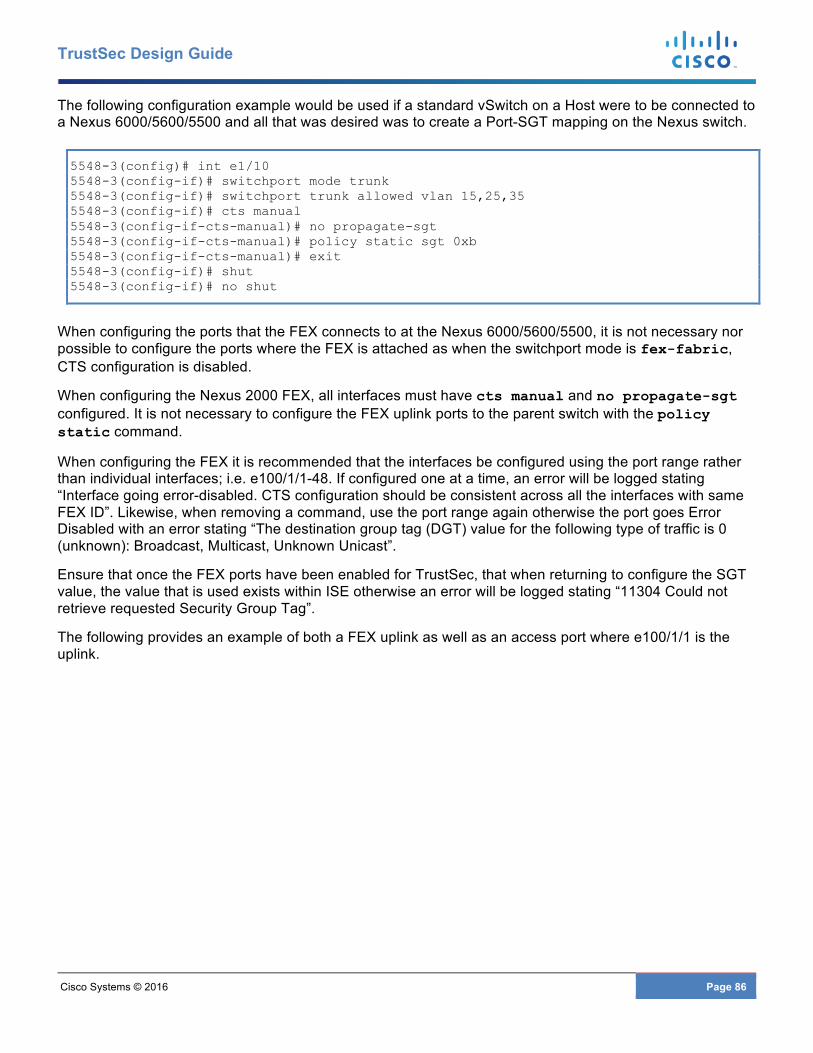
Cisco Systems © 2016 Page 86
TrustSec Design Guide
The following configuration example would be used if a standard vSwitch on a Host were to be connected to a Nexus 6000/5600/5500 and all that was desired was to create a Port-SGT mapping on the Nexus switch.
5548-3(config)# int e1/10 5548-3(config-if)# switchport mode trunk 5548-3(config-if)# switchport trunk allowed vlan 15,25,35 5548-3(config-if)# cts manual 5548-3(config-if-cts-manual)# no propagate-sgt 5548-3(config-if-cts-manual)# policy static sgt 0xb 5548-3(config-if-cts-manual)# exit 5548-3(config-if)# shut 5548-3(config-if)# no shut
When configuring the ports that the FEX connects to at the Nexus 6000/5600/5500, it is not necessary nor possible to configure the ports where the FEX is attached as when the switchport mode is fex-fabric, CTS configuration is disabled.
When configuring the Nexus 2000 FEX, all interfaces must have cts manual and no propagate-sgt configured. It is not necessary to configure the FEX uplink ports to the parent switch with the policy static command.
When configuring the FEX it is recommended that the interfaces be configured using the port range rather than individual interfaces; i.e. e100/1/1-48. If configured one at a time, an error will be logged stating “Interface going error-disabled. CTS configuration should be consistent across all the interfaces with same FEX ID”. Likewise, when removing a command, use the port range again otherwise the port goes Error Disabled with an error stating “The destination group tag (DGT) value for the following type of traffic is 0 (unknown): Broadcast, Multicast, Unknown Unicast”.
Ensure that once the FEX ports have been enabled for TrustSec, that when returning to configure the SGT value, the value that is used exists within ISE otherwise an error will be logged stating “11304 Could not retrieve requested Security Group Tag”.
The following provides an example of both a FEX uplink as well as an access port where e100/1/1 is the uplink.
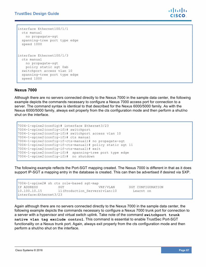
Cisco Systems © 2016 Page 87
TrustSec Design Guide
interface Ethernet100/1/1 cts manual no propagate-sgt spanning-tree port type edge speed 1000 interface Ethernet100/1/3 cts manual no propagate-sgt policy static sgt 0xb switchport access vlan 10 spanning-tree port type edge speed 1000
Nexus 7000
Although there are no servers connected directly to the Nexus 7000 in the sample data center, the following example depicts the commands necessary to configure a Nexus 7000 access port for connection to a server. The command syntax is identical to that described for the Nexus 6000/5000 family. As with the Nexus 6000/5000 family, always exit properly from the cts configuration mode and then perform a shut/no shut on the interface.
7004-1-spine2(config)# interface Ethernet3/23 7004-1-spine2(config-if)# switchport 7004-1-spine2(config-if)# switchport access vlan 10 7004-1-spine2(config-if)# cts manual 7004-1-spine2(config-if-cts-manual)# no propagate-sgt 7004-1-spine2(config-if-cts-manual)# policy static sgt 11 7004-1-spine2(config-if-cts-manual)# exit 7004-1-spine2(config-if)# spanning-tree port type edge 7004-1-spine2(config-if)# no shutdown
The following example reflects the Port-SGT mapping created. The Nexus 7000 is different in that as it does support IP-SGT a mapping entry in the database is created. This can then be advertised if desired via SXP.
7004-1-spine2# sh cts role-based sgt-map IP ADDRESS SGT VRF/VLAN SGT CONFIGURATION 10.100.10.15 11(Production_Servers)vlan:10 Learnt on interface:Ethernet3/23
Again although there are no servers connected directly to the Nexus 7000 in the sample data center, the following example depicts the commands necessary to configure a Nexus 7000 trunk port for connection to a server with a hypervisor and virtual switch uplink. Take note of the command switchport trunk native vlan tag exclude control. This command is essential to enable TrustSec Port-SGT functionality on a Nexus trunk port. Again, always exit properly from the cts configuration mode and then perform a shut/no shut on the interface.
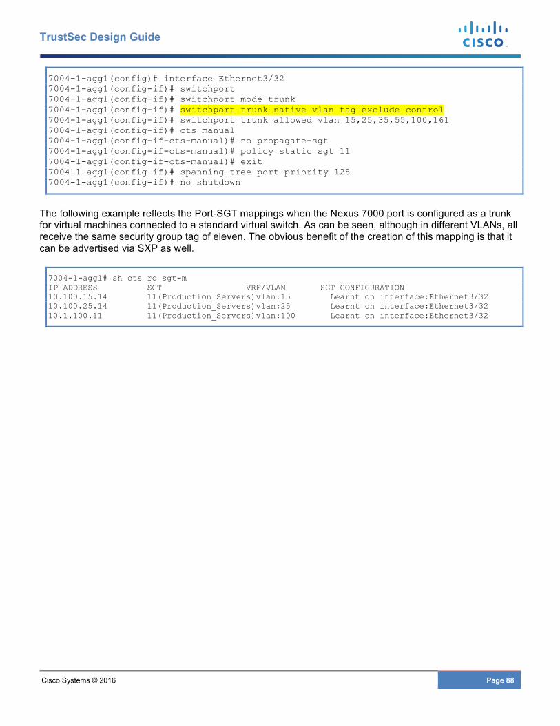
Cisco Systems © 2016 Page 88
TrustSec Design Guide
7004-1-agg1(config)# interface Ethernet3/32 7004-1-agg1(config-if)# switchport 7004-1-agg1(config-if)# switchport mode trunk 7004-1-agg1(config-if)# switchport trunk native vlan tag exclude control 7004-1-agg1(config-if)# switchport trunk allowed vlan 15,25,35,55,100,161 7004-1-agg1(config-if)# cts manual 7004-1-agg1(config-if-cts-manual)# no propagate-sgt 7004-1-agg1(config-if-cts-manual)# policy static sgt 11 7004-1-agg1(config-if-cts-manual)# exit 7004-1-agg1(config-if)# spanning-tree port-priority 128 7004-1-agg1(config-if)# no shutdown
The following example reflects the Port-SGT mappings when the Nexus 7000 port is configured as a trunk for virtual machines connected to a standard virtual switch. As can be seen, although in different VLANs, all receive the same security group tag of eleven. The obvious benefit of the creation of this mapping is that it can be advertised via SXP as well.
7004-1-agg1# sh cts ro sgt-m IP ADDRESS SGT VRF/VLAN SGT CONFIGURATION 10.100.15.14 11(Production_Servers)vlan:15 Learnt on interface:Ethernet3/32 10.100.25.14 11(Production_Servers)vlan:25 Learnt on interface:Ethernet3/32 10.1.100.11 11(Production_Servers)vlan:100 Learnt on interface:Ethernet3/32
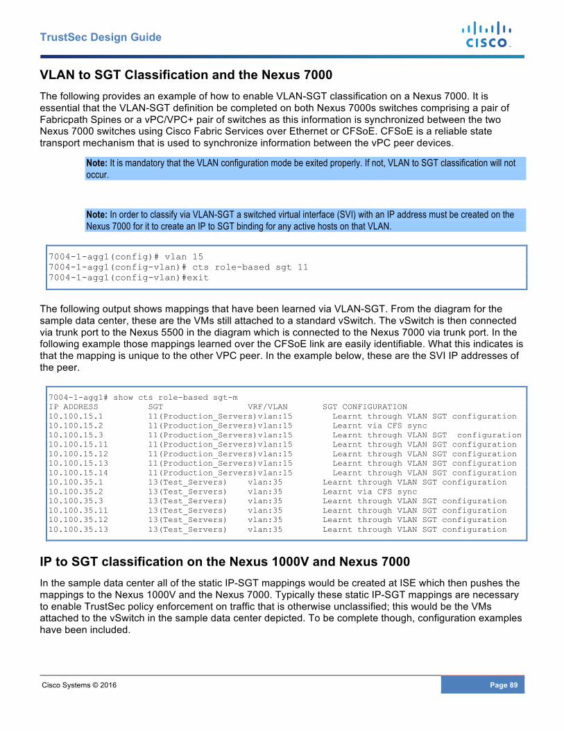
Cisco Systems © 2016 Page 89
TrustSec Design Guide
VLAN to SGT Classification and the Nexus 7000 The following provides an example of how to enable VLAN-SGT classification on a Nexus 7000. It is essential that the VLAN-SGT definition be completed on both Nexus 7000s switches comprising a pair of Fabricpath Spines or a vPC/VPC+ pair of switches as this information is synchronized between the two Nexus 7000 switches using Cisco Fabric Services over Ethernet or CFSoE. CFSoE is a reliable state transport mechanism that is used to synchronize information between the vPC peer devices.
Note: It is mandatory that the VLAN configuration mode be exited properly. If not, VLAN to SGT classification will not occur.
Note: In order to classify via VLAN-SGT a switched virtual interface (SVI) with an IP address must be created on the Nexus 7000 for it to create an IP to SGT binding for any active hosts on that VLAN.
7004-1-agg1(config)# vlan 15 7004-1-agg1(config-vlan)# cts role-based sgt 11 7004-1-agg1(config-vlan)#exit
The following output shows mappings that have been learned via VLAN-SGT. From the diagram for the sample data center, these are the VMs still attached to a standard vSwitch. The vSwitch is then connected via trunk port to the Nexus 5500 in the diagram which is connected to the Nexus 7000 via trunk port. In the following example those mappings learned over the CFSoE link are easily identifiable. What this indicates is that the mapping is unique to the other VPC peer. In the example below, these are the SVI IP addresses of the peer.
7004-1-agg1# show cts role-based sgt-m IP ADDRESS SGT VRF/VLAN SGT CONFIGURATION 10.100.15.1 11(Production_Servers)vlan:15 Learnt through VLAN SGT configuration 10.100.15.2 11(Production_Servers)vlan:15 Learnt via CFS sync 10.100.15.3 11(Production_Servers)vlan:15 Learnt through VLAN SGT configuration 10.100.15.11 11(Production_Servers)vlan:15 Learnt through VLAN SGT configuration 10.100.15.12 11(Production_Servers)vlan:15 Learnt through VLAN SGT configuration 10.100.15.13 11(Production_Servers)vlan:15 Learnt through VLAN SGT configuration 10.100.15.14 11(Production_Servers)vlan:15 Learnt through VLAN SGT configuration 10.100.35.1 13(Test_Servers) vlan:35 Learnt through VLAN SGT configuration 10.100.35.2 13(Test_Servers) vlan:35 Learnt via CFS sync 10.100.35.3 13(Test_Servers) vlan:35 Learnt through VLAN SGT configuration 10.100.35.11 13(Test_Servers) vlan:35 Learnt through VLAN SGT configuration 10.100.35.12 13(Test_Servers) vlan:35 Learnt through VLAN SGT configuration 10.100.35.13 13(Test_Servers) vlan:35 Learnt through VLAN SGT configuration
IP to SGT classification on the Nexus 1000V and Nexus 7000 In the sample data center all of the static IP-SGT mappings would be created at ISE which then pushes the mappings to the Nexus 1000V and the Nexus 7000. Typically these static IP-SGT mappings are necessary to enable TrustSec policy enforcement on traffic that is otherwise unclassified; this would be the VMs attached to the vSwitch in the sample data center depicted. To be complete though, configuration examples have been included.
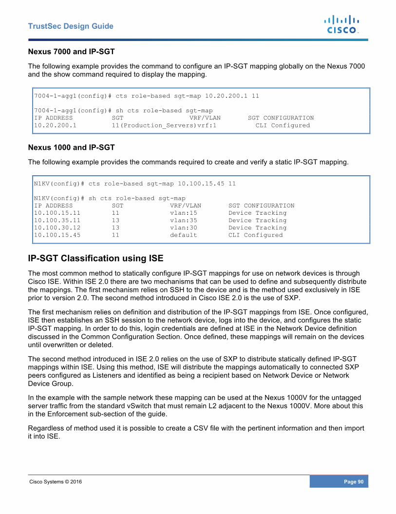
Cisco Systems © 2016 Page 90
TrustSec Design Guide
Nexus 7000 and IP-SGT
The following example provides the command to configure an IP-SGT mapping globally on the Nexus 7000 and the show command required to display the mapping.
7004-1-agg1(config)# cts role-based sgt-map 10.20.200.1 11 7004-1-agg1(config)# sh cts role-based sgt-map IP ADDRESS SGT VRF/VLAN SGT CONFIGURATION 10.20.200.1 11(Production_Servers)vrf:1 CLI Configured
Nexus 1000 and IP-SGT
The following example provides the commands required to create and verify a static IP-SGT mapping.
N1KV(config)# cts role-based sgt-map 10.100.15.45 11 N1KV(config)# sh cts role-based sgt-map IP ADDRESS SGT VRF/VLAN SGT CONFIGURATION 10.100.15.11 11 vlan:15 Device Tracking 10.100.35.11 13 vlan:35 Device Tracking 10.100.30.12 13 vlan:30 Device Tracking 10.100.15.45 11 default CLI Configured
IP-SGT Classification using ISE The most common method to statically configure IP-SGT mappings for use on network devices is through Cisco ISE. Within ISE 2.0 there are two mechanisms that can be used to define and subsequently distribute the mappings. The first mechanism relies on SSH to the device and is the method used exclusively in ISE prior to version 2.0. The second method introduced in Cisco ISE 2.0 is the use of SXP.
The first mechanism relies on definition and distribution of the IP-SGT mappings from ISE. Once configured, ISE then establishes an SSH session to the network device, logs into the device, and configures the static IP-SGT mapping. In order to do this, login credentials are defined at ISE in the Network Device definition discussed in the Common Configuration Section. Once defined, these mappings will remain on the devices until overwritten or deleted.
The second method introduced in ISE 2.0 relies on the use of SXP to distribute statically defined IP-SGT mappings within ISE. Using this method, ISE will distribute the mappings automatically to connected SXP peers configured as Listeners and identified as being a recipient based on Network Device or Network Device Group.
In the example with the sample network these mapping can be used at the Nexus 1000V for the untagged server traffic from the standard vSwitch that must remain L2 adjacent to the Nexus 1000V. More about this in the Enforcement sub-section of the guide.
Regardless of method used it is possible to create a CSV file with the pertinent information and then import it into ISE.
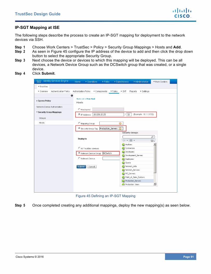
Cisco Systems © 2016 Page 91
TrustSec Design Guide
IP-SGT Mapping at ISE
The following steps describe the process to create an IP-SGT mapping for deployment to the network devices via SSH.
Step 1 Choose Work Centers > TrustSec > Policy > Security Group Mappings > Hosts and Add. Step 2 As seen in Figure 45 configure the IP address of the device to add and then click the drop down
button to select the appropriate Security Group. Step 3 Next choose the device or devices to which this mapping will be deployed. This can be all
devices, a Network Device Group such as the DCSwitch group that was created, or a single device.
Step 4 Click Submit.
Figure 45 Defining an IP-SGT Mapping
Step 5 Once completed creating any additional mappings, deploy the new mapping(s) as seen below.
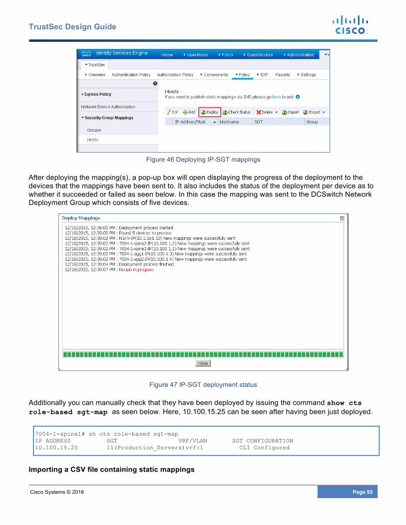
Cisco Systems © 2016 Page 92
TrustSec Design Guide
Figure 46 Deploying IP-SGT mappings
After deploying the mapping(s), a pop-up box will open displaying the progress of the deployment to the devices that the mappings have been sent to. It also includes the status of the deployment per device as to whether it succeeded or failed as seen below. In this case the mapping was sent to the DCSwitch Network Deployment Group which consists of five devices.
Figure 47 IP-SGT deployment status
Additionally you can manually check that they have been deployed by issuing the command show cts role-based sgt-map as seen below. Here, 10.100.15.25 can be seen after having been just deployed.
7004-1-spine1# sh cts role-based sgt-map IP ADDRESS SGT VRF/VLAN SGT CONFIGURATION 10.100.15.25 11(Production_Servers)vrf:1 CLI Configured
Importing a CSV file containing static mappings
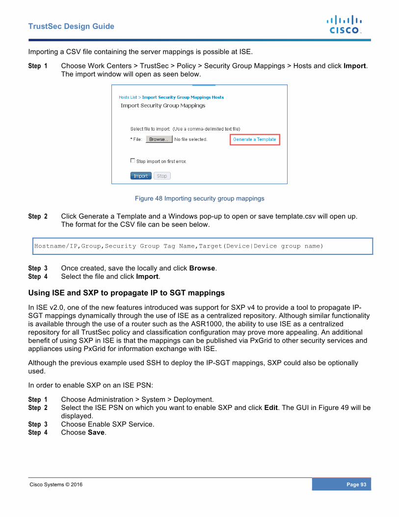
Cisco Systems © 2016 Page 93
TrustSec Design Guide
Importing a CSV file containing the server mappings is possible at ISE.
Step 1 Choose Work Centers > TrustSec > Policy > Security Group Mappings > Hosts and click Import. The import window will open as seen below.
Figure 48 Importing security group mappings
Step 2 Click Generate a Template and a Windows pop-up to open or save template.csv will open up. The format for the CSV file can be seen below.
Hostname/IP,Group,Security Group Tag Name,Target(Device|Device group name)
Step 3 Once created, save the locally and click Browse. Step 4 Select the file and click Import.
Using ISE and SXP to propagate IP to SGT mappings
In ISE v2.0, one of the new features introduced was support for SXP v4 to provide a tool to propagate IP-SGT mappings dynamically through the use of ISE as a centralized repository. Although similar functionality is available through the use of a router such as the ASR1000, the ability to use ISE as a centralized repository for all TrustSec policy and classification configuration may prove more appealing. An additional benefit of using SXP in ISE is that the mappings can be published via PxGrid to other security services and appliances using PxGrid for information exchange with ISE.
Although the previous example used SSH to deploy the IP-SGT mappings, SXP could also be optionally used.
In order to enable SXP on an ISE PSN:
Step 1 Choose Administration > System > Deployment. Step 2 Select the ISE PSN on which you want to enable SXP and click Edit. The GUI in Figure 49 will be
displayed. Step 3 Choose Enable SXP Service. Step 4 Choose Save.
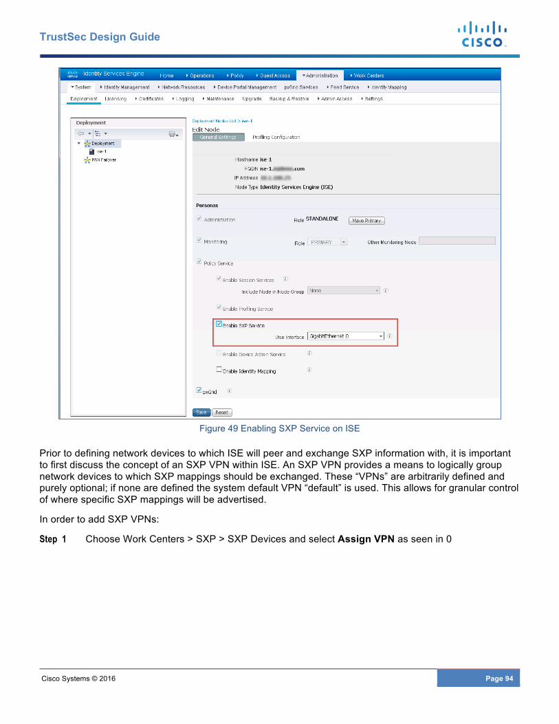
Cisco Systems © 2016 Page 94
TrustSec Design Guide
Figure 49 Enabling SXP Service on ISE
Prior to defining network devices to which ISE will peer and exchange SXP information with, it is important to first discuss the concept of an SXP VPN within ISE. An SXP VPN provides a means to logically group network devices to which SXP mappings should be exchanged. These “VPNs” are arbitrarily defined and purely optional; if none are defined the system default VPN “default” is used. This allows for granular control of where specific SXP mappings will be advertised.
In order to add SXP VPNs:
Step 1 Choose Work Centers > SXP > SXP Devices and select Assign VPN as seen in 0
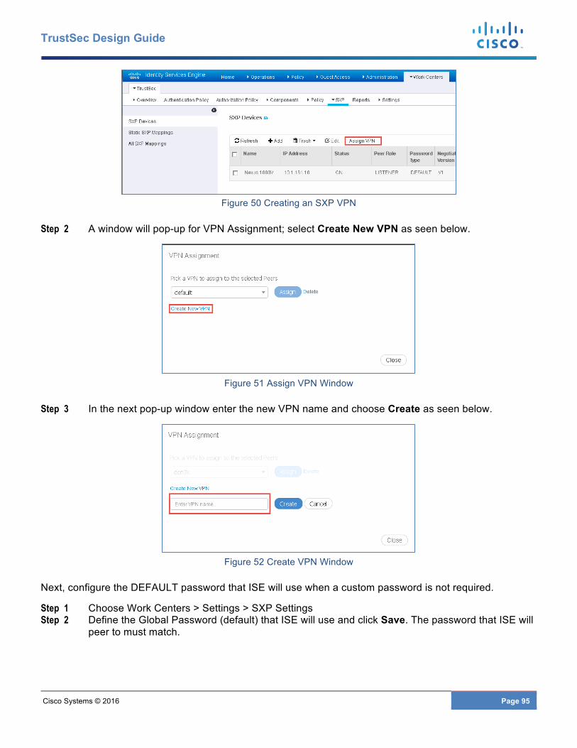
Cisco Systems © 2016 Page 95
TrustSec Design Guide
Figure 50 Creating an SXP VPN
Step 2 A window will pop-up for VPN Assignment; select Create New VPN as seen below.
Figure 51 Assign VPN Window
Step 3 In the next pop-up window enter the new VPN name and choose Create as seen below.
Figure 52 Create VPN Window
Next, configure the DEFAULT password that ISE will use when a custom password is not required.
Step 1 Choose Work Centers > Settings > SXP Settings Step 2 Define the Global Password (default) that ISE will use and click Save. The password that ISE will
peer to must match.
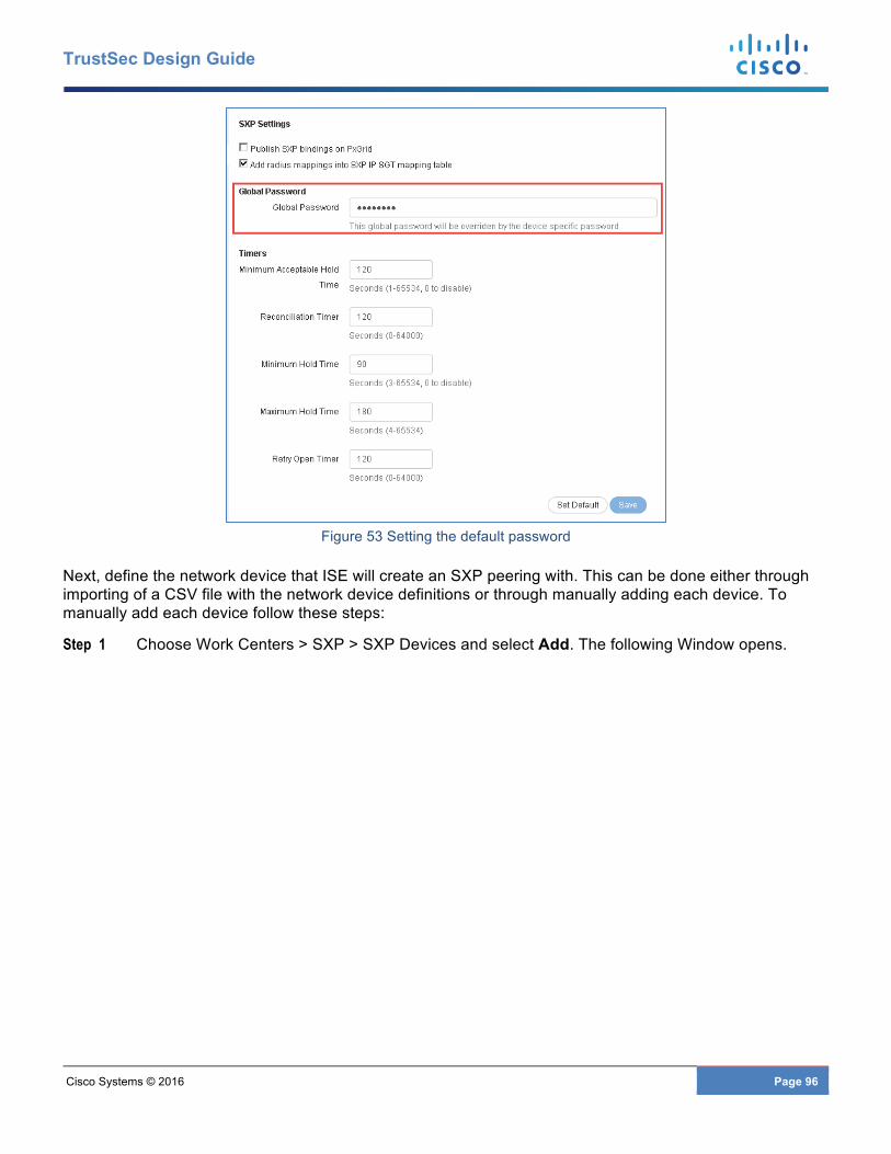
Cisco Systems © 2016 Page 96
TrustSec Design Guide
Figure 53 Setting the default password
Next, define the network device that ISE will create an SXP peering with. This can be done either through importing of a CSV file with the network device definitions or through manually adding each device. To manually add each device follow these steps:
Step 1 Choose Work Centers > SXP > SXP Devices and select Add. The following Window opens.

Cisco Systems © 2016 Page 97
TrustSec Design Guide
Figure 54 Adding SXP peers manually
Step 2 Enter the IP Address of the peer, and select the role of the peer, the password type, and the SXP version supported by the peer. As the default password was just defined it can be left as is or if a unique password other than the default is required, select CUSTOM from the drop-down and enter the password in the Global Password field.
Step 3 Click in the field for Connected PSNs, a list of all of the PSNs will be displayed from which the appropriate one can be selected.
Step 4 Click Save.
Once the device has been added, the “SXP Devices” summary will show the new entry as seen below.
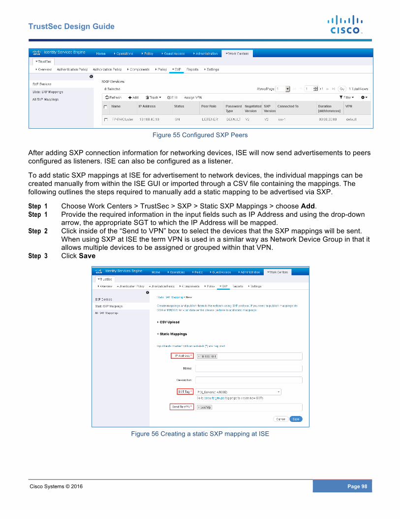
Cisco Systems © 2016 Page 98
TrustSec Design Guide
Figure 55 Configured SXP Peers
After adding SXP connection information for networking devices, ISE will now send advertisements to peers configured as listeners. ISE can also be configured as a listener.
To add static SXP mappings at ISE for advertisement to network devices, the individual mappings can be created manually from within the ISE GUI or imported through a CSV file containing the mappings. The following outlines the steps required to manually add a static mapping to be advertised via SXP.
Step 1 Choose Work Centers > TrustSec > SXP > Static SXP Mappings > choose Add. Step 1 Provide the required information in the input fields such as IP Address and using the drop-down
arrow, the appropriate SGT to which the IP Address will be mapped. Step 2 Click inside of the “Send to VPN” box to select the devices that the SXP mappings will be sent.
When using SXP at ISE the term VPN is used in a similar way as Network Device Group in that it allows multiple devices to be assigned or grouped within that VPN.
Step 3 Click Save
Figure 56 Creating a static SXP mapping at ISE
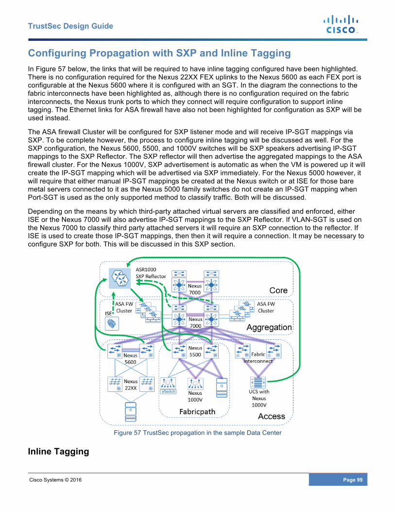
Cisco Systems © 2016 Page 99
TrustSec Design Guide
Configuring Propagation with SXP and Inline Tagging In Figure 57 below, the links that will be required to have inline tagging configured have been highlighted. There is no configuration required for the Nexus 22XX FEX uplinks to the Nexus 5600 as each FEX port is configurable at the Nexus 5600 where it is configured with an SGT. In the diagram the connections to the fabric interconnects have been highlighted as, although there is no configuration required on the fabric interconnects, the Nexus trunk ports to which they connect will require configuration to support inline tagging. The Ethernet links for ASA firewall have also not been highlighted for configuration as SXP will be used instead.
The ASA firewall Cluster will be configured for SXP listener mode and will receive IP-SGT mappings via SXP. To be complete however, the process to configure inline tagging will be discussed as well. For the SXP configuration, the Nexus 5600, 5500, and 1000V switches will be SXP speakers advertising IP-SGT mappings to the SXP Reflector. The SXP reflector will then advertise the aggregated mappings to the ASA firewall cluster. For the Nexus 1000V, SXP advertisement is automatic as when the VM is powered up it will create the IP-SGT mapping which will be advertised via SXP immediately. For the Nexus 5000 however, it will require that either manual IP-SGT mappings be created at the Nexus switch or at ISE for those bare metal servers connected to it as the Nexus 5000 family switches do not create an IP-SGT mapping when Port-SGT is used as the only supported method to classify traffic. Both will be discussed.
Depending on the means by which third-party attached virtual servers are classified and enforced, either ISE or the Nexus 7000 will also advertise IP-SGT mappings to the SXP Reflector. If VLAN-SGT is used on the Nexus 7000 to classify third party attached servers it will require an SXP connection to the reflector. If ISE is used to create those IP-SGT mappings, then then it will require a connection. It may be necessary to configure SXP for both. This will be discussed in this SXP section.
Figure 57 TrustSec propagation in the sample Data Center
Inline Tagging
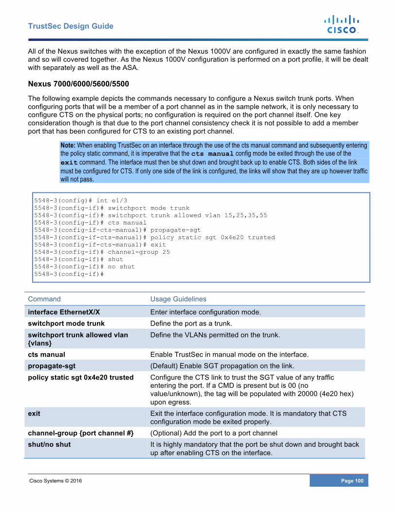
Cisco Systems © 2016 Page 100
TrustSec Design Guide
All of the Nexus switches with the exception of the Nexus 1000V are configured in exactly the same fashion and so will covered together. As the Nexus 1000V configuration is performed on a port profile, it will be dealt with separately as well as the ASA.
Nexus 7000/6000/5600/5500
The following example depicts the commands necessary to configure a Nexus switch trunk ports. When configuring ports that will be a member of a port channel as in the sample network, it is only necessary to configure CTS on the physical ports; no configuration is required on the port channel itself. One key consideration though is that due to the port channel consistency check it is not possible to add a member port that has been configured for CTS to an existing port channel.
Note: When enabling TrustSec on an interface through the use of the cts manual command and subsequently entering the policy static command, it is imperative that the cts manual config mode be exited through the use of the exit command. The interface must then be shut down and brought back up to enable CTS. Both sides of the link must be configured for CTS. If only one side of the link is configured, the links will show that they are up however traffic will not pass.
5548-3(config)# int e1/3 5548-3(config-if)# switchport mode trunk 5548-3(config-if)# switchport trunk allowed vlan 15,25,35,55 5548-3(config-if)# cts manual 5548-3(config-if-cts-manual)# propagate-sgt 5548-3(config-if-cts-manual)# policy static sgt 0x4e20 trusted 5548-3(config-if-cts-manual)# exit 5548-3(config-if)# channel-group 25 5548-3(config-if)# shut 5548-3(config-if)# no shut 5548-3(config-if)#
Command Usage Guidelines
interface EthernetX/X Enter interface configuration mode. switchport mode trunk Define the port as a trunk. switchport trunk allowed vlan {vlans}
Define the VLANs permitted on the trunk.
cts manual Enable TrustSec in manual mode on the interface. propagate-sgt (Default) Enable SGT propagation on the link. policy static sgt 0x4e20 trusted Configure the CTS link to trust the SGT value of any traffic
entering the port. If a CMD is present but is 00 (no value/unknown), the tag will be populated with 20000 (4e20 hex) upon egress.
exit Exit the interface configuration mode. It is mandatory that CTS configuration mode be exited properly.
channel-group {port channel #} (Optional) Add the port to a port channel shut/no shut It is highly mandatory that the port be shut down and brought back
up after enabling CTS on the interface.
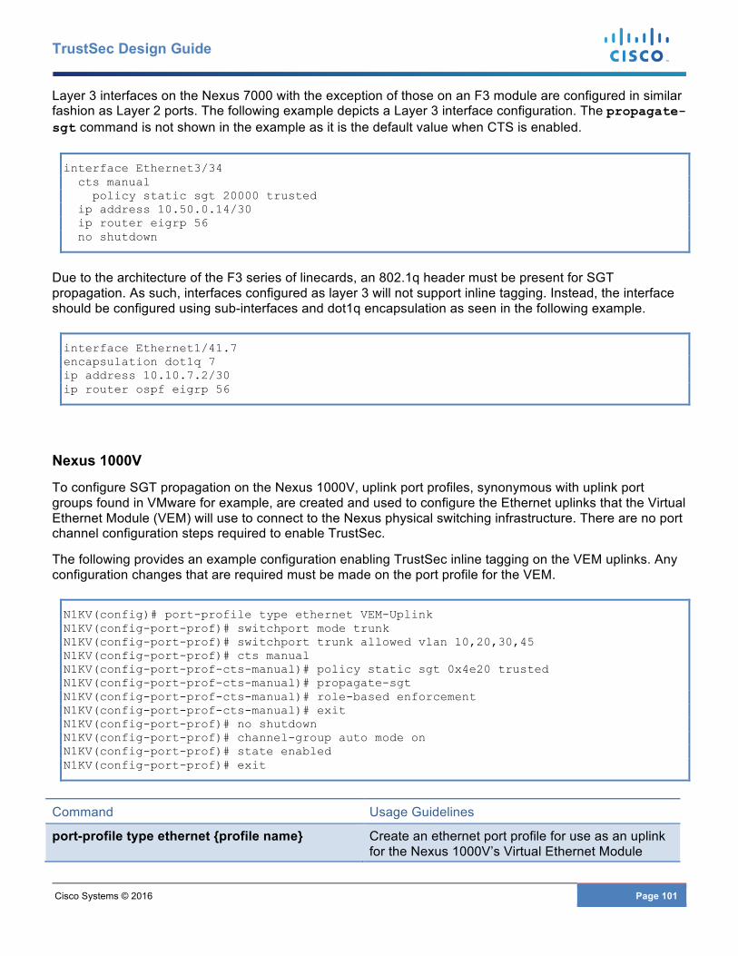
Cisco Systems © 2016 Page 101
TrustSec Design Guide
Layer 3 interfaces on the Nexus 7000 with the exception of those on an F3 module are configured in similar fashion as Layer 2 ports. The following example depicts a Layer 3 interface configuration. The propagate-sgt command is not shown in the example as it is the default value when CTS is enabled.
interface Ethernet3/34 cts manual policy static sgt 20000 trusted ip address 10.50.0.14/30 ip router eigrp 56 no shutdown
Due to the architecture of the F3 series of linecards, an 802.1q header must be present for SGT propagation. As such, interfaces configured as layer 3 will not support inline tagging. Instead, the interface should be configured using sub-interfaces and dot1q encapsulation as seen in the following example.
interface Ethernet1/41.7 encapsulation dot1q 7 ip address 10.10.7.2/30 ip router ospf eigrp 56
Nexus 1000V
To configure SGT propagation on the Nexus 1000V, uplink port profiles, synonymous with uplink port groups found in VMware for example, are created and used to configure the Ethernet uplinks that the Virtual Ethernet Module (VEM) will use to connect to the Nexus physical switching infrastructure. There are no port channel configuration steps required to enable TrustSec.
The following provides an example configuration enabling TrustSec inline tagging on the VEM uplinks. Any configuration changes that are required must be made on the port profile for the VEM.
N1KV(config)# port-profile type ethernet VEM-Uplink N1KV(config-port-prof)# switchport mode trunk N1KV(config-port-prof)# switchport trunk allowed vlan 10,20,30,45 N1KV(config-port-prof)# cts manual N1KV(config-port-prof-cts-manual)# policy static sgt 0x4e20 trusted N1KV(config-port-prof-cts-manual)# propagate-sgt N1KV(config-port-prof-cts-manual)# role-based enforcement N1KV(config-port-prof-cts-manual)# exit N1KV(config-port-prof)# no shutdown N1KV(config-port-prof)# channel-group auto mode on N1KV(config-port-prof)# state enabled N1KV(config-port-prof)# exit
Command Usage Guidelines
port-profile type ethernet {profile name} Create an ethernet port profile for use as an uplink for the Nexus 1000V’s Virtual Ethernet Module
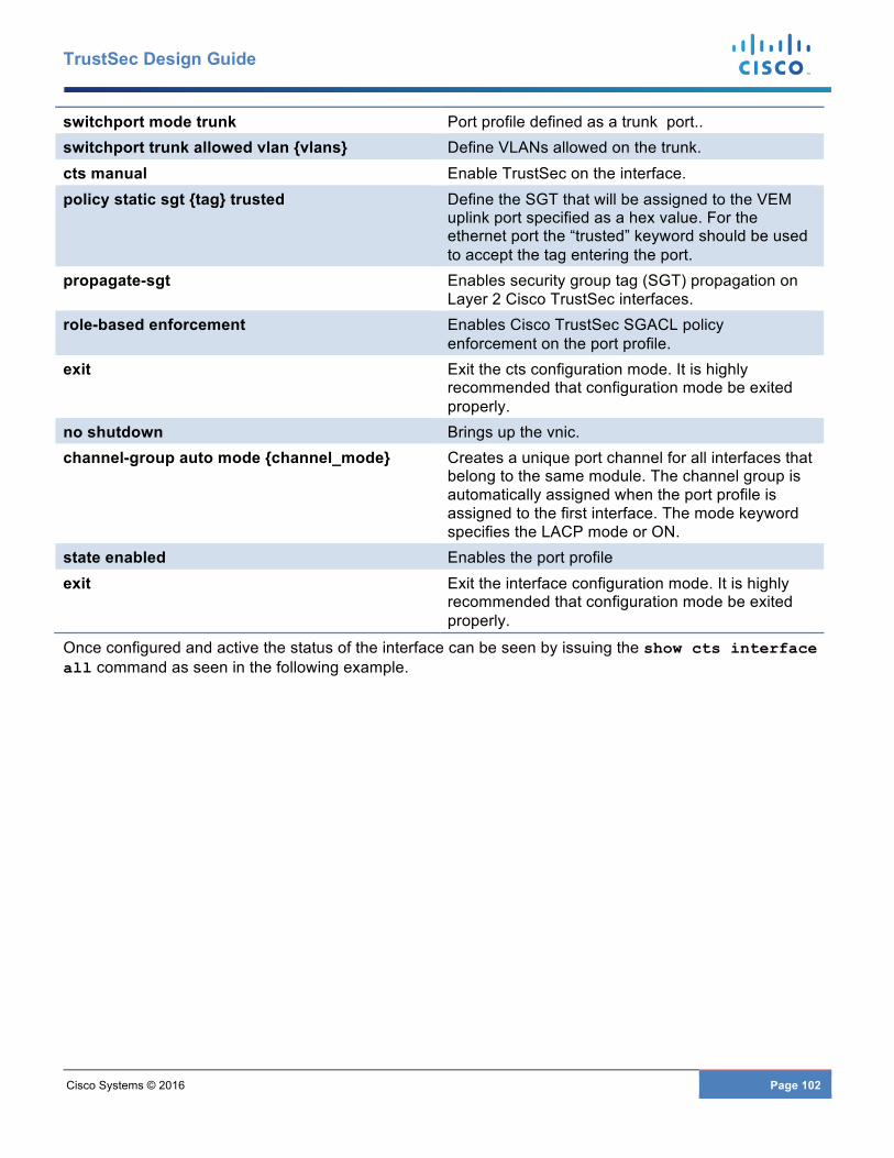
Cisco Systems © 2016 Page 102
TrustSec Design Guide
switchport mode trunk Port profile defined as a trunk port.. switchport trunk allowed vlan {vlans} Define VLANs allowed on the trunk. cts manual Enable TrustSec on the interface. policy static sgt {tag} trusted Define the SGT that will be assigned to the VEM
uplink port specified as a hex value. For the ethernet port the “trusted” keyword should be used to accept the tag entering the port.
propagate-sgt Enables security group tag (SGT) propagation on Layer 2 Cisco TrustSec interfaces.
role-based enforcement Enables Cisco TrustSec SGACL policy enforcement on the port profile.
exit Exit the cts configuration mode. It is highly recommended that configuration mode be exited properly.
no shutdown Brings up the vnic. channel-group auto mode {channel_mode} Creates a unique port channel for all interfaces that
belong to the same module. The channel group is automatically assigned when the port profile is assigned to the first interface. The mode keyword specifies the LACP mode or ON.
state enabled Enables the port profile exit Exit the interface configuration mode. It is highly
recommended that configuration mode be exited properly.
Once configured and active the status of the interface can be seen by issuing the show cts interface all command as seen in the following example.
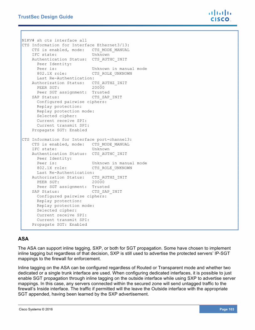
Cisco Systems © 2016 Page 103
TrustSec Design Guide
N1KV# sh cts interface all CTS Information for Interface Ethernet3/13: CTS is enabled, mode: CTS_MODE_MANUAL IFC state: Unknown Authentication Status: CTS_AUTHC_INIT Peer Identity: Peer is: Unknown in manual mode 802.1X role: CTS_ROLE_UNKNOWN Last Re-Authentication: Authorization Status: CTS_AUTHZ_INIT PEER SGT: 20000 Peer SGT assignment: Trusted SAP Status: CTS_SAP_INIT Configured pairwise ciphers: Replay protection: Replay protection mode: Selected cipher: Current receive SPI: Current transmit SPI: Propagate SGT: Enabled CTS Information for Interface port-channel3: CTS is enabled, mode: CTS_MODE_MANUAL IFC state: Unknown Authentication Status: CTS_AUTHC_INIT Peer Identity: Peer is: Unknown in manual mode 802.1X role: CTS_ROLE_UNKNOWN Last Re-Authentication: Authorization Status: CTS_AUTHZ_INIT PEER SGT: 20000 Peer SGT assignment: Trusted SAP Status: CTS_SAP_INIT Configured pairwise ciphers: Replay protection: Replay protection mode: Selected cipher: Current receive SPI: Current transmit SPI: Propagate SGT: Enabled
ASA
The ASA can support inline tagging, SXP, or both for SGT propagation. Some have chosen to implement inline tagging but regardless of that decision, SXP is still used to advertise the protected servers’ IP-SGT mappings to the firewall for enforcement.
Inline tagging on the ASA can be configured regardless of Routed or Transparent mode and whether two dedicated or a single trunk interface are used. When configuring dedicated interfaces, it is possible to just enable SGT propagation through inline tagging on the outside interface while using SXP to advertise server mappings. In this case, any servers connected within the secured zone will send untagged traffic to the firewall’s Inside interface. The traffic if permitted will the leave the Outside interface with the appropriate SGT appended, having been learned by the SXP advertisement.
Cisco Systems © 2016 Page 104
TrustSec Design Guide
If a single trunk interface is used, both inside and Outside interfaces will require inline tagging to be configured as the Nexus switch port to which it attaches requires the CTS configuration on the physical layer 2 interface configured as a trunk.
Regardless of the use of inline tagging, the second task in configuring the firewall will be configuring SXP to advertise the IP-SGT mapping of the servers protected by the firewall. SXP configuration examples will be provided in the upcoming section regarding SXP configuration.
To be complete, the following example shows the configuration required when a transparent firewall with a single trunk interface is used. The sample configuration for a Nexus interface, discussed earlier, should be used at the other side of the link. In the sample below, two physical interfaces are shown as the firewall is dual-homed to the Nexus 7000 switches comprising the data center distribution layer.
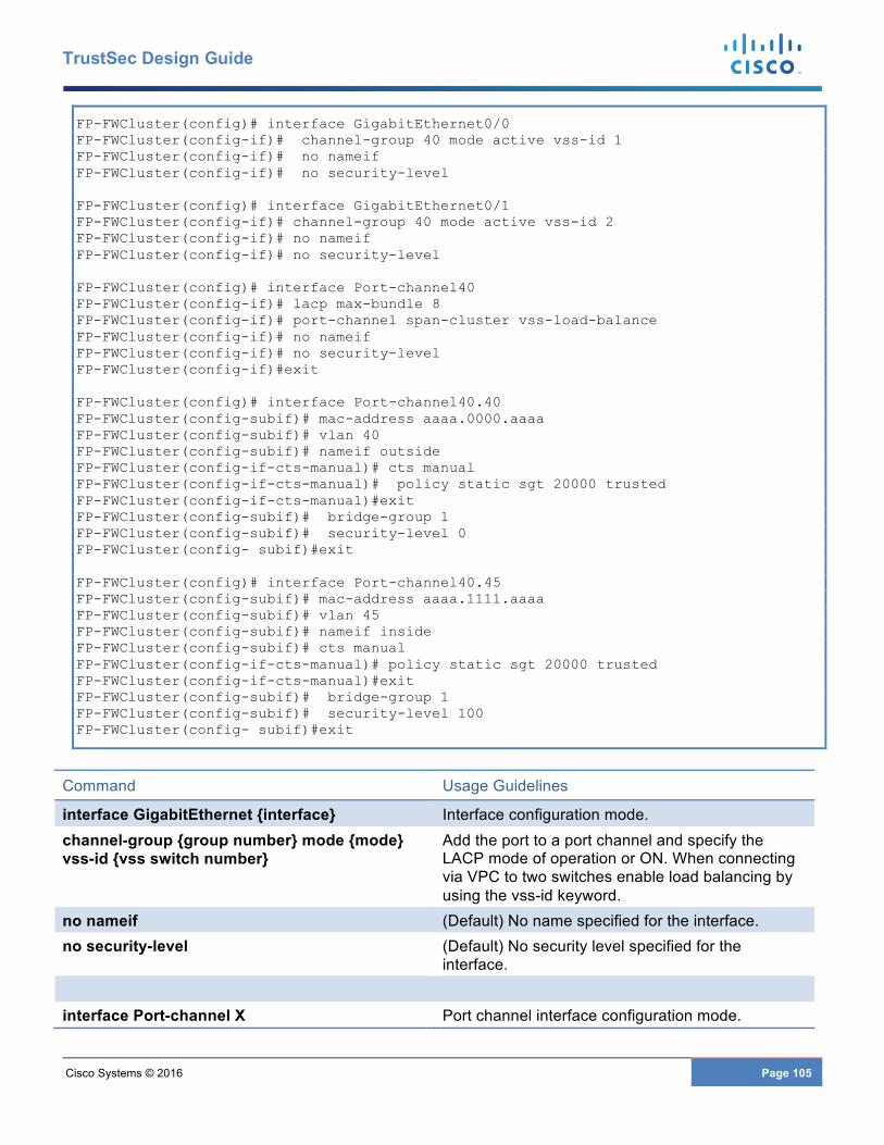
Cisco Systems © 2016 Page 105
TrustSec Design Guide
FP-FWCluster(config)# interface GigabitEthernet0/0 FP-FWCluster(config-if)# channel-group 40 mode active vss-id 1 FP-FWCluster(config-if)# no nameif FP-FWCluster(config-if)# no security-level FP-FWCluster(config)# interface GigabitEthernet0/1 FP-FWCluster(config-if)# channel-group 40 mode active vss-id 2 FP-FWCluster(config-if)# no nameif FP-FWCluster(config-if)# no security-level FP-FWCluster(config)# interface Port-channel40 FP-FWCluster(config-if)# lacp max-bundle 8 FP-FWCluster(config-if)# port-channel span-cluster vss-load-balance FP-FWCluster(config-if)# no nameif FP-FWCluster(config-if)# no security-level FP-FWCluster(config-if)#exit FP-FWCluster(config)# interface Port-channel40.40 FP-FWCluster(config-subif)# mac-address aaaa.0000.aaaa FP-FWCluster(config-subif)# vlan 40 FP-FWCluster(config-subif)# nameif outside FP-FWCluster(config-if-cts-manual)# cts manual FP-FWCluster(config-if-cts-manual)# policy static sgt 20000 trusted FP-FWCluster(config-if-cts-manual)#exit FP-FWCluster(config-subif)# bridge-group 1 FP-FWCluster(config-subif)# security-level 0 FP-FWCluster(config- subif)#exit FP-FWCluster(config)# interface Port-channel40.45 FP-FWCluster(config-subif)# mac-address aaaa.1111.aaaa FP-FWCluster(config-subif)# vlan 45 FP-FWCluster(config-subif)# nameif inside FP-FWCluster(config-subif)# cts manual FP-FWCluster(config-if-cts-manual)# policy static sgt 20000 trusted FP-FWCluster(config-if-cts-manual)#exit FP-FWCluster(config-subif)# bridge-group 1 FP-FWCluster(config-subif)# security-level 100 FP-FWCluster(config- subif)#exit
Command Usage Guidelines
interface GigabitEthernet {interface} Interface configuration mode. channel-group {group number} mode {mode} vss-id {vss switch number}
Add the port to a port channel and specify the LACP mode of operation or ON. When connecting via VPC to two switches enable load balancing by using the vss-id keyword.
no nameif (Default) No name specified for the interface. no security-level (Default) No security level specified for the
interface. interface Port-channel X Port channel interface configuration mode.
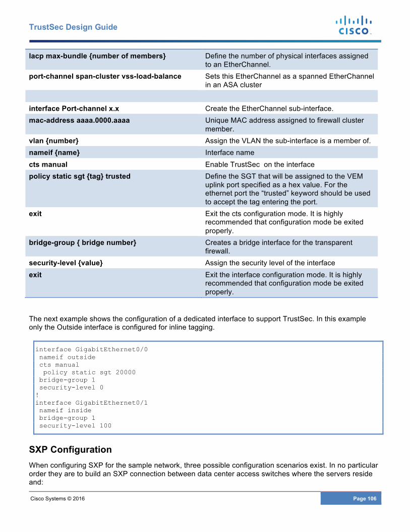
Cisco Systems © 2016 Page 106
TrustSec Design Guide
lacp max-bundle {number of members} Define the number of physical interfaces assigned to an EtherChannel.
port-channel span-cluster vss-load-balance Sets this EtherChannel as a spanned EtherChannel in an ASA cluster
interface Port-channel x.x Create the EtherChannel sub-interface. mac-address aaaa.0000.aaaa Unique MAC address assigned to firewall cluster
member. vlan {number} Assign the VLAN the sub-interface is a member of. nameif {name} Interface name cts manual Enable TrustSec on the interface policy static sgt {tag} trusted Define the SGT that will be assigned to the VEM
uplink port specified as a hex value. For the ethernet port the “trusted” keyword should be used to accept the tag entering the port.
exit Exit the cts configuration mode. It is highly recommended that configuration mode be exited properly.
bridge-group { bridge number} Creates a bridge interface for the transparent firewall.
security-level {value} Assign the security level of the interface exit Exit the interface configuration mode. It is highly
recommended that configuration mode be exited properly.
The next example shows the configuration of a dedicated interface to support TrustSec. In this example only the Outside interface is configured for inline tagging.
interface GigabitEthernet0/0 nameif outside cts manual policy static sgt 20000 bridge-group 1 security-level 0 ! interface GigabitEthernet0/1 nameif inside bridge-group 1 security-level 100
SXP Configuration When configuring SXP for the sample network, three possible configuration scenarios exist. In no particular order they are to build an SXP connection between data center access switches where the servers reside and:
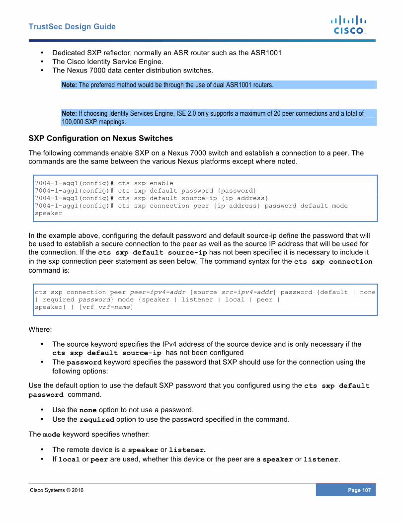
Cisco Systems © 2016 Page 107
TrustSec Design Guide
• Dedicated SXP reflector; normally an ASR router such as the ASR1001 • The Cisco Identity Service Engine. • The Nexus 7000 data center distribution switches.
Note: The preferred method would be through the use of dual ASR1001 routers.
Note: If choosing Identity Services Engine, ISE 2.0 only supports a maximum of 20 peer connections and a total of 100,000 SXP mappings.
SXP Configuration on Nexus Switches
The following commands enable SXP on a Nexus 7000 switch and establish a connection to a peer. The commands are the same between the various Nexus platforms except where noted.
7004-1-agg1(config)# cts sxp enable 7004-1-agg1(config)# cts sxp default password {password} 7004-1-agg1(config)# cts sxp default source-ip {ip address} 7004-1-agg1(config)# cts sxp connection peer {ip address} password default mode speaker
In the example above, configuring the default password and default source-ip define the password that will be used to establish a secure connection to the peer as well as the source IP address that will be used for the connection. If the cts sxp default source-ip has not been specified it is necessary to include it in the sxp connection peer statement as seen below. The command syntax for the cts sxp connection command is:
cts sxp connection peer peer-ipv4-addr [source src-ipv4-addr] password {default | none | required password} mode {speaker | listener | local | peer | speaker} } [vrf vrf-name]
Where:
• The source keyword specifies the IPv4 address of the source device and is only necessary if the cts sxp default source-ip has not been configured
• The password keyword specifies the password that SXP should use for the connection using the following options:
Use the default option to use the default SXP password that you configured using the cts sxp default password command.
• Use the none option to not use a password. • Use the required option to use the password specified in the command.
The mode keyword specifies whether:
• The remote device is a speaker or listener. • If local or peer are used, whether this device or the peer are a speaker or listener.
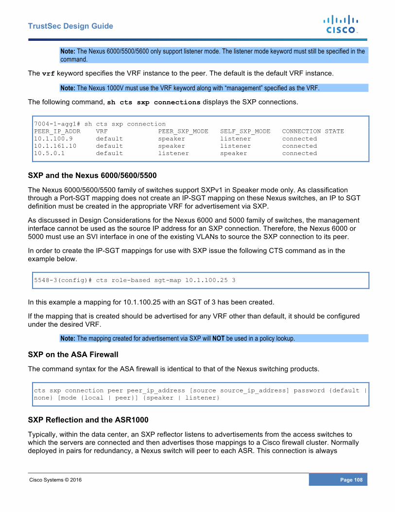
Cisco Systems © 2016 Page 108
TrustSec Design Guide
Note: The Nexus 6000/5500/5600 only support listener mode. The listener mode keyword must still be specified in the command.
The vrf keyword specifies the VRF instance to the peer. The default is the default VRF instance.
Note: The Nexus 1000V must use the VRF keyword along with “management” specified as the VRF.
The following command, sh cts sxp connections displays the SXP connections.
7004-1-agg1# sh cts sxp connection PEER_IP_ADDR VRF PEER_SXP_MODE SELF_SXP_MODE CONNECTION STATE 10.1.100.9 default speaker listener connected 10.1.161.10 default speaker listener connected 10.5.0.1 default listener speaker connected
SXP and the Nexus 6000/5600/5500
The Nexus 6000/5600/5500 family of switches support SXPv1 in Speaker mode only. As classification through a Port-SGT mapping does not create an IP-SGT mapping on these Nexus switches, an IP to SGT definition must be created in the appropriate VRF for advertisement via SXP.
As discussed in Design Considerations for the Nexus 6000 and 5000 family of switches, the management interface cannot be used as the source IP address for an SXP connection. Therefore, the Nexus 6000 or 5000 must use an SVI interface in one of the existing VLANs to source the SXP connection to its peer.
In order to create the IP-SGT mappings for use with SXP issue the following CTS command as in the example below.
5548-3(config)# cts role-based sgt-map 10.1.100.25 3
In this example a mapping for 10.1.100.25 with an SGT of 3 has been created.
If the mapping that is created should be advertised for any VRF other than default, it should be configured under the desired VRF.
Note: The mapping created for advertisement via SXP will NOT be used in a policy lookup.
SXP on the ASA Firewall
The command syntax for the ASA firewall is identical to that of the Nexus switching products.
cts sxp connection peer peer_ip_address [source source_ip_address] password {default | none} [mode {local | peer}] {speaker | listener}
SXP Reflection and the ASR1000
Typically, within the data center, an SXP reflector listens to advertisements from the access switches to which the servers are connected and then advertises those mappings to a Cisco firewall cluster. Normally deployed in pairs for redundancy, a Nexus switch will peer to each ASR. This connection is always
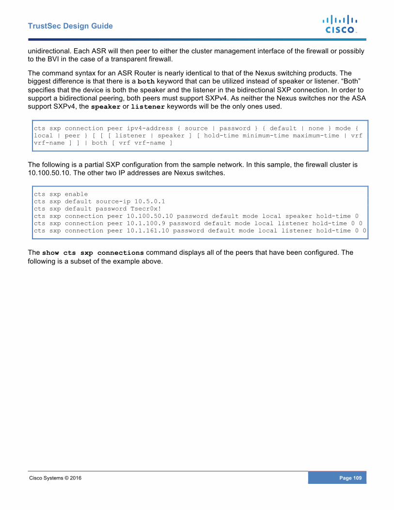
Cisco Systems © 2016 Page 109
TrustSec Design Guide
unidirectional. Each ASR will then peer to either the cluster management interface of the firewall or possibly to the BVI in the case of a transparent firewall.
The command syntax for an ASR Router is nearly identical to that of the Nexus switching products. The biggest difference is that there is a both keyword that can be utilized instead of speaker or listener. “Both” specifies that the device is both the speaker and the listener in the bidirectional SXP connection. In order to support a bidirectional peering, both peers must support SXPv4. As neither the Nexus switches nor the ASA support SXPv4, the speaker or listener keywords will be the only ones used.
cts sxp connection peer ipv4-address { source | password } { default | none } mode { local | peer } [ [ [ listener | speaker ] [ hold-time minimum-time maximum-time | vrf vrf-name ] ] | both [ vrf vrf-name ]
The following is a partial SXP configuration from the sample network. In this sample, the firewall cluster is 10.100.50.10. The other two IP addresses are Nexus switches.
cts sxp enable cts sxp default source-ip 10.5.0.1 cts sxp default password Tsecr0x! cts sxp connection peer 10.100.50.10 password default mode local speaker hold-time 0 cts sxp connection peer 10.1.100.9 password default mode local listener hold-time 0 0 cts sxp connection peer 10.1.161.10 password default mode local listener hold-time 0 0
The show cts sxp connections command displays all of the peers that have been configured. The following is a subset of the example above.
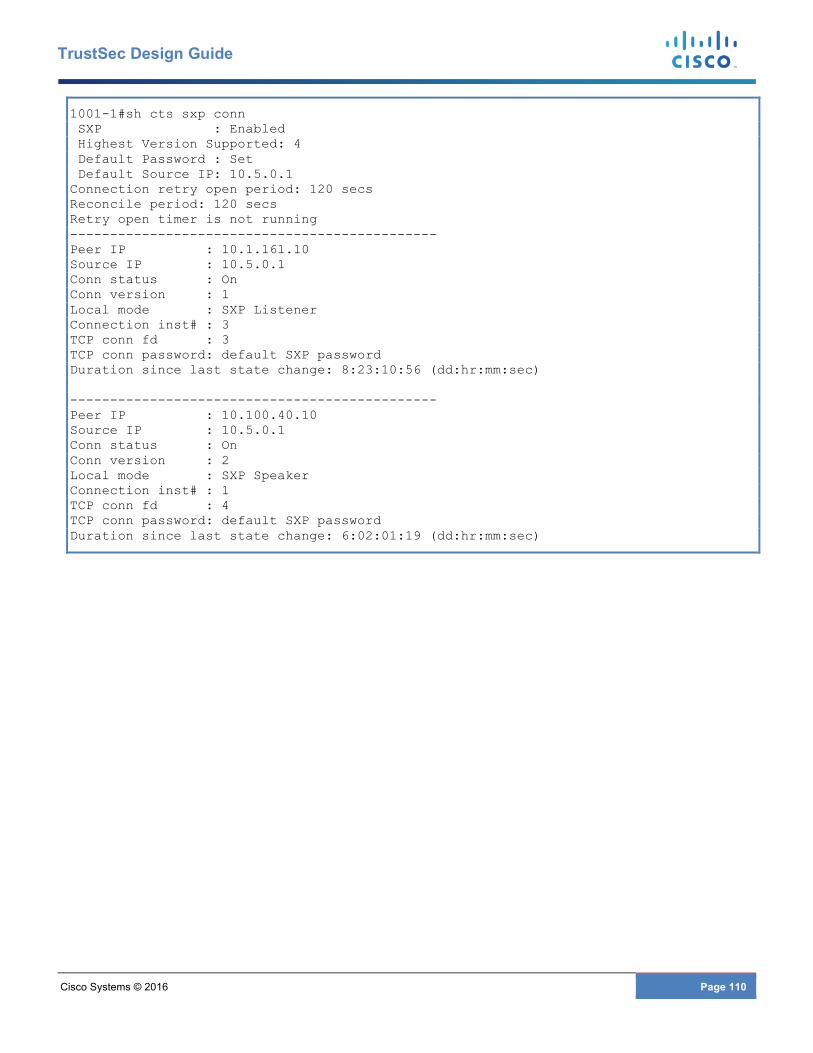
Cisco Systems © 2016 Page 110
TrustSec Design Guide
1001-1#sh cts sxp conn SXP : Enabled Highest Version Supported: 4 Default Password : Set Default Source IP: 10.5.0.1 Connection retry open period: 120 secs Reconcile period: 120 secs Retry open timer is not running ---------------------------------------------- Peer IP : 10.1.161.10 Source IP : 10.5.0.1 Conn status : On Conn version : 1 Local mode : SXP Listener Connection inst# : 3 TCP conn fd : 3 TCP conn password: default SXP password Duration since last state change: 8:23:10:56 (dd:hr:mm:sec) ---------------------------------------------- Peer IP : 10.100.40.10 Source IP : 10.5.0.1 Conn status : On Conn version : 2 Local mode : SXP Speaker Connection inst# : 1 TCP conn fd : 4 TCP conn password: default SXP password Duration since last state change: 6:02:01:19 (dd:hr:mm:sec)
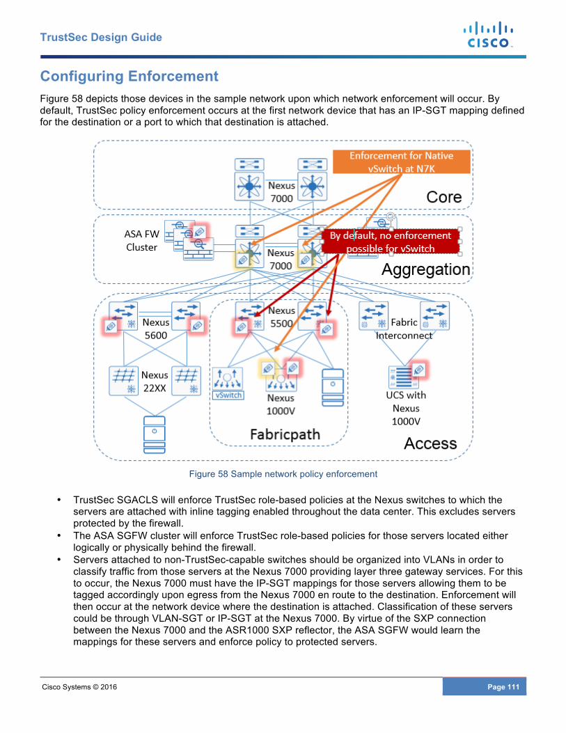
Cisco Systems © 2016 Page 111
TrustSec Design Guide
Configuring Enforcement Figure 58 depicts those devices in the sample network upon which network enforcement will occur. By default, TrustSec policy enforcement occurs at the first network device that has an IP-SGT mapping defined for the destination or a port to which that destination is attached.
Figure 58 Sample network policy enforcement
• TrustSec SGACLS will enforce TrustSec role-based policies at the Nexus switches to which the servers are attached with inline tagging enabled throughout the data center. This excludes servers protected by the firewall.
• The ASA SGFW cluster will enforce TrustSec role-based policies for those servers located either logically or physically behind the firewall.
• Servers attached to non-TrustSec-capable switches should be organized into VLANs in order to classify traffic from those servers at the Nexus 7000 providing layer three gateway services. For this to occur, the Nexus 7000 must have the IP-SGT mappings for those servers allowing them to be tagged accordingly upon egress from the Nexus 7000 en route to the destination. Enforcement will then occur at the network device where the destination is attached. Classification of these servers could be through VLAN-SGT or IP-SGT at the Nexus 7000. By virtue of the SXP connection between the Nexus 7000 and the ASR1000 SXP reflector, the ASA SGFW would learn the mappings for these servers and enforce policy to protected servers.
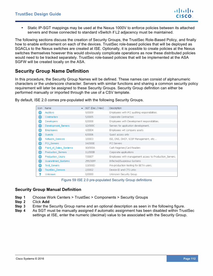
Cisco Systems © 2016 Page 112
TrustSec Design Guide
• Static IP-SGT mappings may be used at the Nexus 1000V to enforce policies between its attached servers and those connected to standard vSwitch if L2 adjacency must be maintained.
The following sections discuss the creation of Security Groups, the TrustSec Role-Based Policy, and finally how to enable enforcement on each of the devices. TrustSec role-based policies that will be deployed as SGACLs to the Nexus switches are created at ISE. Optionally, it is possible to create policies at the Nexus switches themselves however this would obviously complicate operations as now these distributed policies would need to be tracked separately. TrustSec role-based policies that will be implemented at the ASA SGFW will be created locally on the ASA.
Security Group Name Definition In this procedure, the Security Group Names will be defined. These names can consist of alphanumeric characters or the underscore character. Servers with similar functions and sharing a common security policy requirement will later be assigned to these Security Groups. Security Group definition can either be performed manually or imported through the use of a CSV template.
By default, ISE 2.0 comes pre-populated with the following Security Groups.
Figure 59 ISE 2.0 pre-populated Security Group definitions
Security Group Manual Definition
Step 1 Choose Work Centers > TrustSec > Components > Security Groups Step 2 Click Add Step 3 Enter the Security Group name and an optional description as seen in the following figure. Step 4 As SGT must be manually assigned if automatic assignment has been disabled within TrustSec
settings at ISE, enter the numeric (decimal) value to be associated with the Security Group.
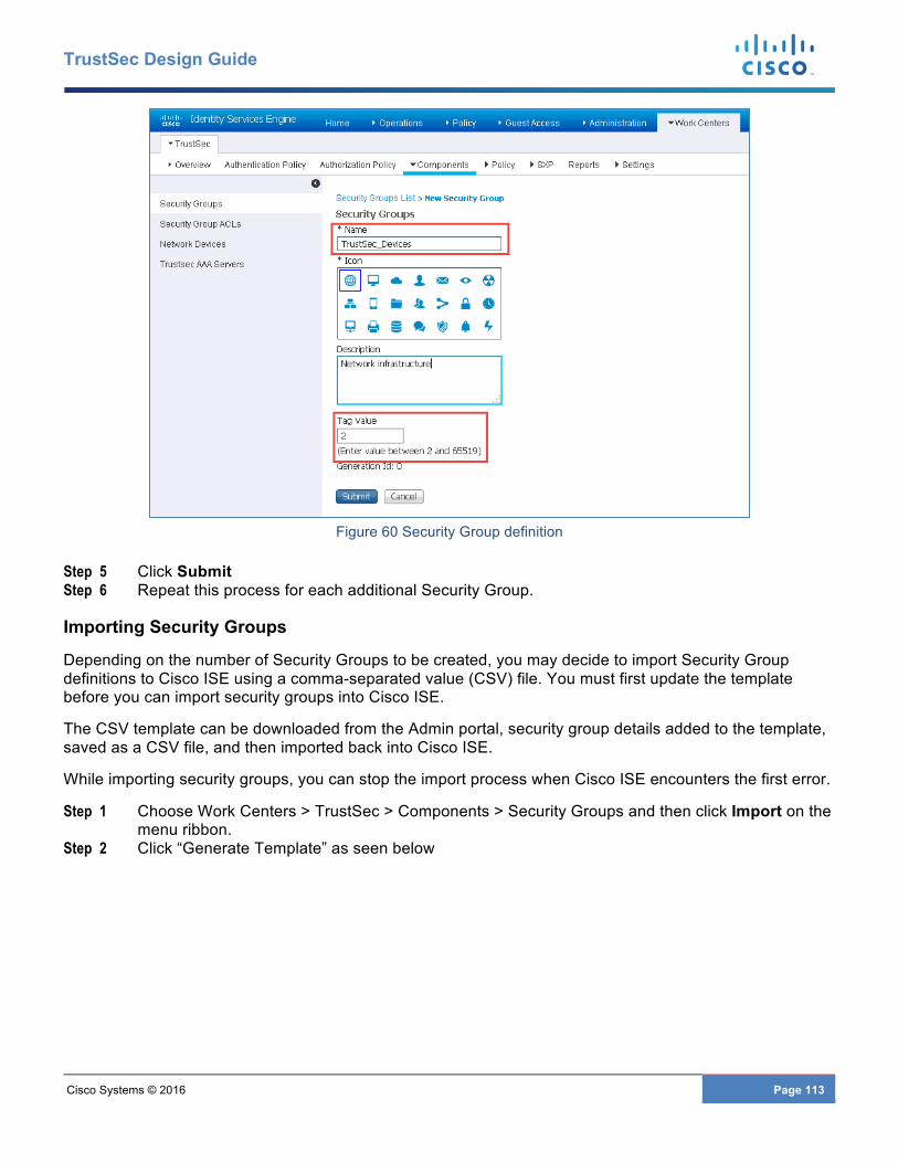
Cisco Systems © 2016 Page 113
TrustSec Design Guide
Figure 60 Security Group definition
Step 5 Click Submit Step 6 Repeat this process for each additional Security Group.
Importing Security Groups
Depending on the number of Security Groups to be created, you may decide to import Security Group definitions to Cisco ISE using a comma-separated value (CSV) file. You must first update the template before you can import security groups into Cisco ISE.
The CSV template can be downloaded from the Admin portal, security group details added to the template, saved as a CSV file, and then imported back into Cisco ISE.
While importing security groups, you can stop the import process when Cisco ISE encounters the first error.
Step 1 Choose Work Centers > TrustSec > Components > Security Groups and then click Import on the menu ribbon.
Step 2 Click “Generate Template” as seen below
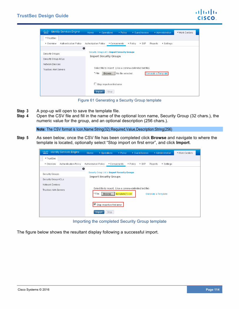
Cisco Systems © 2016 Page 114
TrustSec Design Guide
Figure 61 Generating a Security Group template
Step 3 A pop-up will open to save the template file. Step 4 Open the CSV file and fill in the name of the optional Icon name, Security Group (32 chars.), the
numeric value for the group, and an optional description (256 chars.).
Note: The CSV format is Icon,Name:String(32):Required,Value,Description:String(256)
Step 5 As seen below, once the CSV file has been completed click Browse and navigate to where the template is located, optionally select “Stop import on first error”, and click Import.
Importing the completed Security Group template
The figure below shows the resultant display following a successful import.
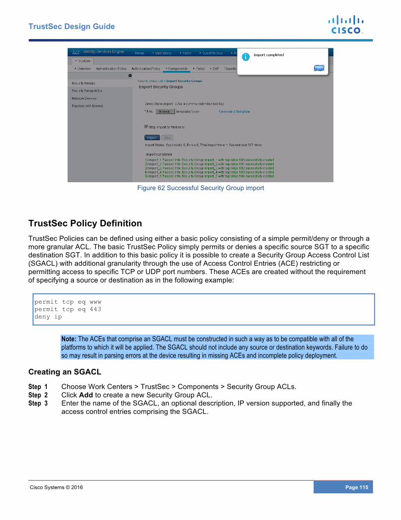
Cisco Systems © 2016 Page 115
TrustSec Design Guide
Figure 62 Successful Security Group import
TrustSec Policy Definition TrustSec Policies can be defined using either a basic policy consisting of a simple permit/deny or through a more granular ACL. The basic TrustSec Policy simply permits or denies a specific source SGT to a specific destination SGT. In addition to this basic policy it is possible to create a Security Group Access Control List (SGACL) with additional granularity through the use of Access Control Entries (ACE) restricting or permitting access to specific TCP or UDP port numbers. These ACEs are created without the requirement of specifying a source or destination as in the following example:
permit tcp eq www permit tcp eq 443 deny ip
Note: The ACEs that comprise an SGACL must be constructed in such a way as to be compatible with all of the platforms to which it will be applied. The SGACL should not include any source or destination keywords. Failure to do so may result in parsing errors at the device resulting in missing ACEs and incomplete policy deployment.
Creating an SGACL
Step 1 Choose Work Centers > TrustSec > Components > Security Group ACLs. Step 2 Click Add to create a new Security Group ACL. Step 3 Enter the name of the SGACL, an optional description, IP version supported, and finally the
access control entries comprising the SGACL.

Cisco Systems © 2016 Page 116
TrustSec Design Guide
Figure 63 SGACL Creation
Step 4 Click Submit
Creating TrustSec Egress Policies
TrustSec Egress Policies can be created through one of three different views.
• Matrix - The Matrix View of the Egress policy looks like a spreadsheet. The mapping of a source SGT to a destination SGT is represented as a cell. If a cell contains data, then it represents that there is a mapping between the corresponding source SGT and the destination SGT.
• Source Tree - The Source Tree view lists a compact and organized view of source SGTs in a collapsed state. This view displays only the source SGTs that are mapped to destination SGTs. If you expand a specific source SGT, it lists all destination SGTs that are mapped to this source SGT and the corresponding policy (SGACLs) in a table.
• Destination Tree - The Destination Tree view lists a compact and organized view of destination SGTs in a collapsed state. This view displays only the destination SGTs that are mapped to source SGTs. If you expand a specific destination SGT, it lists all source SGTs that are mapped to this destination SGT and the corresponding policy (SGACLs) in a table.
Note: When displaying the egress policies from either the source or destination tree view for the first time there will not be any security groups displayed, the matrix view will however show all groups regardless of having a policy defined or not. The source and destination tree views will only display those security groups that have a policy defined.
Step 1 Choose Work Centers > TrustSec > Policy Step 2 By default the Matrix View will open. The new policy can be created either from this window or the
Source or Destination Tree view can be selected based on user preference.
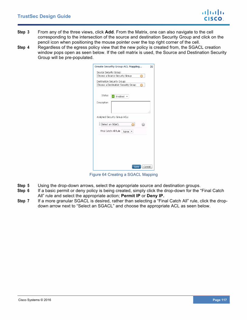
Cisco Systems © 2016 Page 117
TrustSec Design Guide
Step 3 From any of the three views, click Add. From the Matrix, one can also navigate to the cell corresponding to the intersection of the source and destination Security Group and click on the pencil icon when positioning the mouse pointer over the top right corner of the cell.
Step 4 Regardless of the egress policy view that the new policy is created from, the SGACL creation window pops open as seen below. If the cell matrix is used, the Source and Destination Security Group will be pre-populated.
Figure 64 Creating a SGACL Mapping
Step 5 Using the drop-down arrows, select the appropriate source and destination groups. Step 6 If a basic permit or deny policy is being created, simply click the drop-down for the “Final Catch
All” rule and select the appropriate action; Permit IP or Deny IP. Step 7 If a more granular SGACL is desired, rather than selecting a “Final Catch All” rule, click the drop-
down arrow next to “Select an SGACL” and choose the appropriate ACL as seen below.
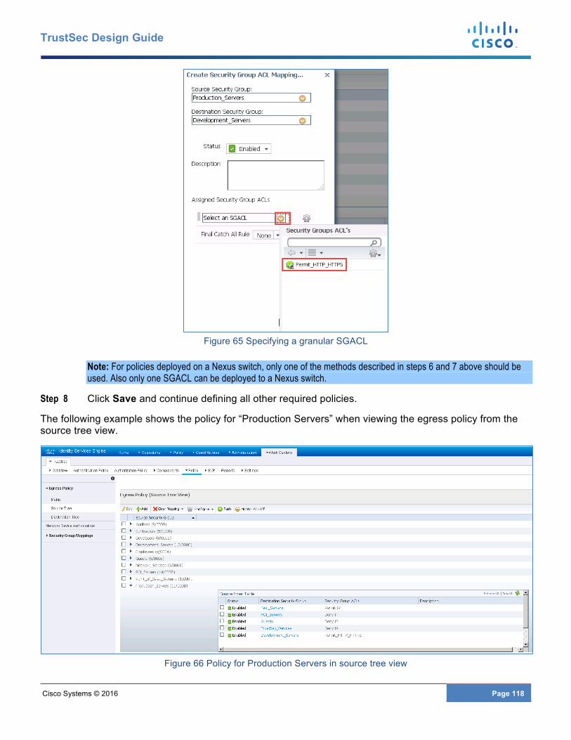
Cisco Systems © 2016 Page 118
TrustSec Design Guide
Figure 65 Specifying a granular SGACL
Note: For policies deployed on a Nexus switch, only one of the methods described in steps 6 and 7 above should be used. Also only one SGACL can be deployed to a Nexus switch.
Step 8 Click Save and continue defining all other required policies.
The following example shows the policy for “Production Servers” when viewing the egress policy from the source tree view.
Figure 66 Policy for Production Servers in source tree view
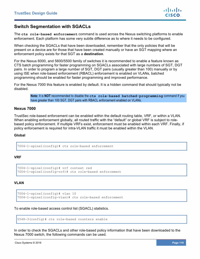
Cisco Systems © 2016 Page 119
TrustSec Design Guide
Switch Segmentation with SGACLs The cts role-based enforcement command is used across the Nexus switching platforms to enable enforcement. Each platform has some very subtle difference as to where it needs to be configured.
When checking the SGACLs that have been downloaded, remember that the only policies that will be present on a device are for those that have been created manually or have an SGT mapping where an enforcement policy exists for that SGT as a destination.
For the Nexus 6000, and 5600/5500 family of switches it is recommended to enable a feature known as CTS batch programming for faster programming on SGACLs associated with large numbers of SGT, DGT pairs. In order to program a large number of SGT, DGT pairs (usually greater than 100) manually or by using ISE when role-based enforcement (RBACL) enforcement is enabled on VLANs, batched programming should be enabled for faster programming and improved performance.
For the Nexus 7000 this feature is enabled by default. It is a hidden command that should typically not be disabled.
Note: It is NOT recommended to disable the cts role-based batched-programming command if you have greater than 100 SGT, DGT pairs with RBACL enforcement enabled on VLANs.
Nexus 7000
TrustSec role-based enforcement can be enabled within the default routing table, VRF, or within a VLAN. When enabling enforcement globally, all routed traffic with the “default” or global VRF is subject to role-based policy enforcement. If multiple VRFs exist, enforcement must be enabled within each VRF. Finally, if policy enforcement is required for intra-VLAN traffic it must be enabled within the VLAN.
Global
7004-1-spine1(config)# cts role-based enforcement
VRF
7004-1-spine1(config)# vrf context red 7004-1-spine1(config-vrf)# cts role-based enforcement
VLAN
7004-1-spine1(config)# vlan 10 7004-1-spine1(config-vlan)# cts role-based enforcement
To enable role-based access control list (SGACL) statistics.
5548-3(config)# cts role-based counters enable
In order to check the SGACLs and other role-based policy information that have been downloaded to the Nexus 7000 switch, the following commands can be used.
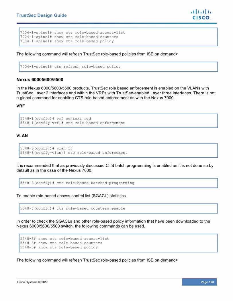
Cisco Systems © 2016 Page 120
TrustSec Design Guide
7004-1-spine1# show cts role-based access-list 7004-1-spine1# show cts role-based counters 7004-1-spine1# show cts role-based policy
The following command will refresh TrustSec role-based policies from ISE on demand>
7004-1-spine1# cts refresh role-based policy
Nexus 60005600/5500
In the Nexus 6000/5600/5500 products, TrustSec role based enforcement is enabled on the VLANs with TrustSec Layer 2 interfaces and within the VRFs with TrustSec-enabled Layer three interfaces. There is not a global command for enabling CTS role-based enforcement as with the Nexus 7000.
VRF
5548-1(config)# vrf context red 5548-1(config-vrf)# cts role-based enforcement
VLAN
5548-3(config)# vlan 10 5548-3(config-vlan)# cts role-based enforcement
It is recommended that as previously discussed CTS batch programming is enabled as it is not done so by default as in the case of the Nexus 7000.
5548-3(config)# cts role-based batched-programming
To enable role-based access control list (SGACL) statistics.
5548-3(config)# cts role-based counters enable
In order to check the SGACLs and other role-based policy information that have been downloaded to the Nexus 6000/5600/5500 switch, the following commands can be used.
5548-3# show cts role-based access-list 5548-3# show cts role-based counters 5548-3# show cts role-based policy
The following command will refresh TrustSec role-based policies from ISE on demand>
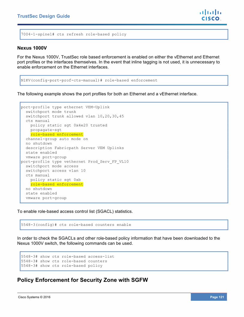
Cisco Systems © 2016 Page 121
TrustSec Design Guide
7004-1-spine1# cts refresh role-based policy
Nexus 1000V
For the Nexus 1000V, TrustSec role based enforcement is enabled on either the vEthernet and Ethernet port profiles or the interfaces themselves. In the event that inline tagging is not used, it is unnecessary to enable enforcement on the Ethernet interfaces.
N1KV(config-port-prof-cts-manual)# role-based enforcement
The following example shows the port profiles for both an Ethernet and a vEthernet interface.
port-profile type ethernet VEM-Uplink switchport mode trunk switchport trunk allowed vlan 10,20,30,45 cts manual policy static sgt 0x4e20 trusted propagate-sgt role-based enforcement channel-group auto mode on no shutdown description Fabricpath Server VEM Uplinks state enabled vmware port-group port-profile type vethernet Prod_Serv_FP_VL10 switchport mode access switchport access vlan 10 cts manual policy static sgt 0xb role-based enforcement no shutdown state enabled vmware port-group
To enable role-based access control list (SGACL) statistics.
5548-3(config)# cts role-based counters enable
In order to check the SGACLs and other role-based policy information that have been downloaded to the Nexus 1000V switch, the following commands can be used.
5548-3# show cts role-based access-list 5548-3# show cts role-based counters 5548-3# show cts role-based policy
Policy Enforcement for Security Zone with SGFW

Cisco Systems © 2016 Page 122
TrustSec Design Guide
In ASA version 9.0(2) or higher software, TrustSec and Security Group Tags were introduced to the ASA platform. When using Security Group Tags to implement role-based policies on the ASA, the firewall is referred to as being a Security Group Firewall or SGFW. SGFW rules can be created through either ASDM or CLI.
The ASA SGFW policies as seen below in Figure 67are created locally on the ASA. The only information that the ASA derives from ISE are the Security Group Names and the associated tag value. In order to obtain this information as was discussed in the “Common Configuration” section, Cisco ISE must be defined as a Radius server on the ASA, a PAC must be generated at ISE and subsequently imported at the ASA. As has been previously discussed, it is possible to create policies not only with source and destination SGTs but with a combination of SGT, IP Addresses, or network objects as the source or destination.
Figure 67 SGFW Enforcement Policies
To create SGFW rules using ASDM adhere to the following procedure. This of course assumes that the initial steps outlined in the Common Configuration section for importing the PAC and downloading TrustSec environment data has been completed.
Step 1 Choose Configuration > Firewall > Access Rules. Step 2 Highlight the desired interface to create the access rule on and click Add. A drop down box will
open as can be seen in. Step 3 Click Add ACL. Step 4 A popup window will open up. Step 5 From the Interface drop-down box, select the appropriate interface. In this example it will be the
“Outside” interface as this will demonstrate the creation of a policy for to the security zone protected by the SGFW.
Step 6 Click the browse button next to the “Source Security Group” box.
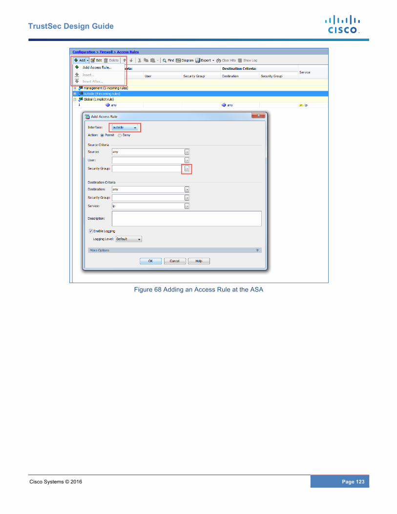
Cisco Systems © 2016 Page 123
TrustSec Design Guide
Figure 68 Adding an Access Rule at the ASA
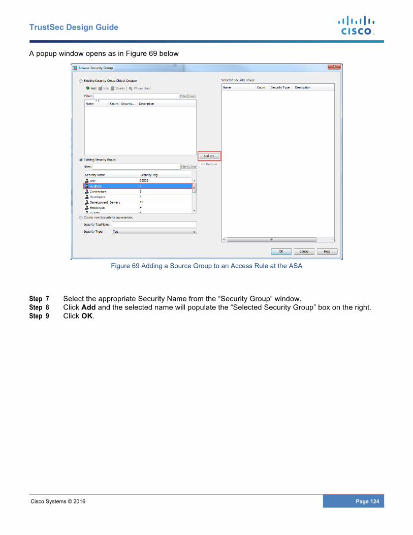
Cisco Systems © 2016 Page 124
TrustSec Design Guide
A popup window opens as in Figure 69 below
Figure 69 Adding a Source Group to an Access Rule at the ASA
Step 7 Select the appropriate Security Name from the “Security Group” window. Step 8 Click Add and the selected name will populate the “Selected Security Group” box on the right. Step 9 Click OK.
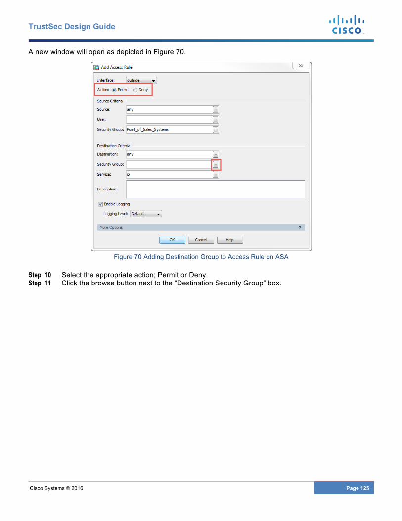
Cisco Systems © 2016 Page 125
TrustSec Design Guide
A new window will open as depicted in Figure 70.
Figure 70 Adding Destination Group to Access Rule on ASA
Step 10 Select the appropriate action; Permit or Deny. Step 11 Click the browse button next to the “Destination Security Group” box.
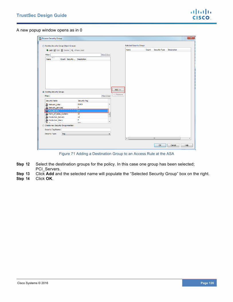
Cisco Systems © 2016 Page 126
TrustSec Design Guide
A new popup window opens as in 0
Figure 71 Adding a Destination Group to an Access Rule at the ASA
Step 12 Select the destination groups for the policy. In this case one group has been selected; PCI_Servers.
Step 13 Click Add and the selected name will populate the “Selected Security Group” box on the right. Step 14 Click OK.
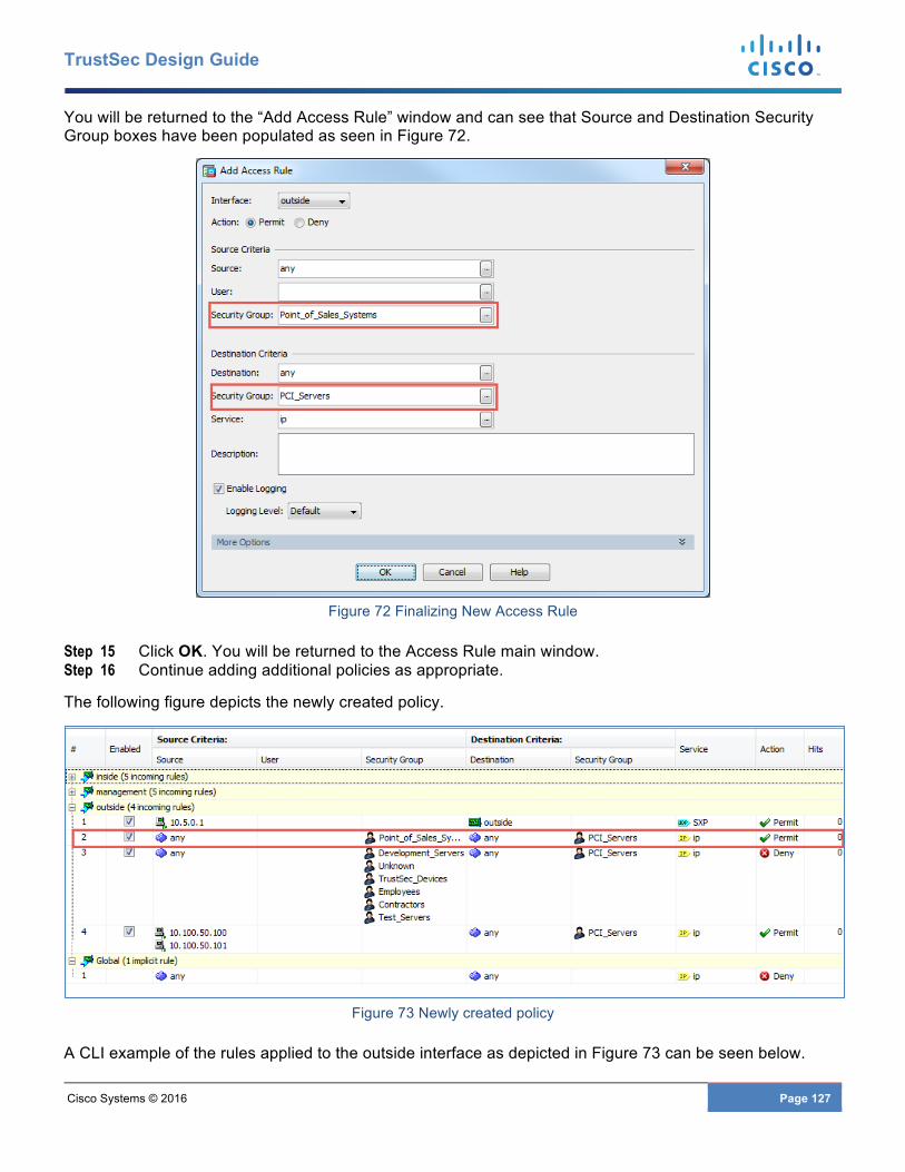
Cisco Systems © 2016 Page 127
TrustSec Design Guide
You will be returned to the “Add Access Rule” window and can see that Source and Destination Security Group boxes have been populated as seen in Figure 72.
Figure 72 Finalizing New Access Rule
Step 15 Click OK. You will be returned to the Access Rule main window. Step 16 Continue adding additional policies as appropriate.
The following figure depicts the newly created policy.
Figure 73 Newly created policy
A CLI example of the rules applied to the outside interface as depicted in Figure 73 can be seen below.
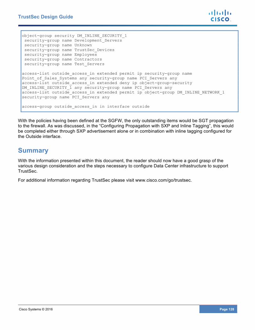
Cisco Systems © 2016 Page 128
TrustSec Design Guide
object-group security DM_INLINE_SECURITY_1 security-group name Development_Servers security-group name Unknown security-group name TrustSec_Devices security-group name Employees security-group name Contractors security-group name Test_Servers access-list outside_access_in extended permit ip security-group name Point_of_Sales_Systems any security-group name PCI_Servers any access-list outside_access_in extended deny ip object-group-security DM_INLINE_SECURITY_1 any security-group name PCI_Servers any access-list outside_access_in extended permit ip object-group DM_INLINE_NETWORK_1 security-group name PCI_Servers any access-group outside_access_in in interface outside
With the policies having been defined at the SGFW, the only outstanding items would be SGT propagation to the firewall. As was discussed, in the “Configuring Propagation with SXP and Inline Tagging”, this would be completed either through SXP advertisement alone or in combination with inline tagging configured for the Outside interface.
Summary With the information presented within this document, the reader should now have a good grasp of the various design consideration and the steps necessary to configure Data Center infrastructure to support TrustSec.
For additional information regarding TrustSec please visit www.cisco.com/go/trustsec.
Cisco Systems © 2016 Page 129
TrustSec Design Guide
APPENDIX A Document Reference Cisco TrustSec Web Page
www.cisco.com/go/trustsec
“Overview of TrustSec
http://www.cisco.com/c/dam/en/us/solutions/collateral/borderless-networks/trustsec/C07-730151-00_overview_of_trustSec_og.pdf
“Cisco TrustSec Quick Start Configuration Guide”
http://www.cisco.com/c/dam/en/us/solutions/collateral/enterprise-networks/trustsec/configuration-guide.pdf.
“Cisco TrustSec Platform and Capability Matrix v5.3”
http://www.cisco.com/c/en/us/solutions/enterprise-networks/trustsec/trustsec_matrix.html
“Cisco FabricPath Best Practices”
http://www.cisco.com/c/dam/en/us/products/collateral/switches/nexus-7000-series-switches/white_paper_c07-728188.pdf
“Cisco FabricPath Design Guide: Using FabricPath with an Aggregation and Access Topology”
http://www.cisco.com/c/en/us/products/collateral/switches/nexus-5000-series-switches/guide_c07-690079.html
“Multi Data Center Sites Deployment of Cisco ASA Clustering with FirePOWER Services - Design and Implementation Guide”
http://www.cisco.com/c/dam/m/en_us/solutions/data-center/offers/efficiency/dc-06_secure_data_center_design_guide_cte_en.pdf
“Massively Scalable Data Center, Design and Implementation” CVD
http://www.cisco.com/c/en/us/td/docs/solutions/Enterprise/Data_Center/MSDC/1-0/MSDC_Phase1.html
IETF draft-smith-kandula-sxp-03”
https://datatracker.ietf.org/doc/draft-smith-kandula-sxp
“Secure Datacenter Portfolio” from within “Design Zone for Data Centers”
http://www.cisco.com/c/en/us/solutions/enterprise/design-zone-data-centers/index.html.

Cisco Systems © 2016 Page 130
TrustSec Design Guide
APPENDIX B Equipment Software Versions Product Software Version
Nexus 7004 with Sup2 7.2(0)D1(1) Nexus 5548 with L3 Daughtercard 7.2(1)N1(1) Nexus 1000V 5.2(1)SV3(1.4) ASA 5515-X Cluster 9.5(2) ASR 1001 15.5(3)S1a - 03.16.01a.S ISE 2.0 VMware 5.1 Windows Server Server 2012 R1
Note: The versions of software used while preparing this document should NOT be considered a recommended release positioned by Cisco. This information is presented only to document the versions of software running on the assorted platforms.