data converters
DESCRIPTION
Data Converters. ELEC 330 Digital Systems Engineering Dr. Ron Hayne Images Courtesy of Ramesh Gaonkar and Delmar Learning. Basic Concepts. Analog Signals Continuous Infinite values in a given range Example Clock face with hands Digital Signals Discrete values On/Off 1/0 Example - PowerPoint PPT PresentationTRANSCRIPT
Data Converters
ELEC 330Digital Systems Engineering
Dr. Ron Hayne
Images Courtesy of Ramesh Gaonkar and Delmar Learning
Basic Concepts
Analog Signals Continuous Infinite values in a given range Example
Clock face with hands
Digital Signals Discrete values
On/Off 1/0
Example Digital clock
2330_12
Basic Concepts
Limitations of analog signals Pick up noise as they are amplified Difficult to store
Advantages of digital signals Noise margin Easily stored in memory
Limitations of digital signals How accurately analog signals are represented
Quantization
3330_12

Embedded System Typical analog/digital system
TransducerConverts non-electrical signals into electrical signals
A/D converterConverts analog signals into digital signals
Digital processor Processes digital data
D/A converterConverts digital signals into equivalent analog signals
TransducerConverts electrical signals into non-electrical signals
4330_12
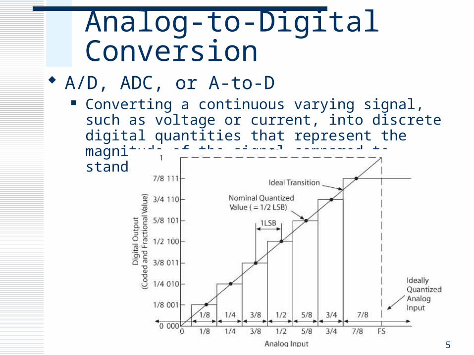
Analog-to-Digital Conversion A/D, ADC, or A-to-D
Converting a continuous varying signal, such as voltage or current, into discrete digital quantities that represent the magnitude of the signal compared to standard or reference
5

A/D Conversion
Flash Uses multiple comparators in parallel High-speed, high cost
Integrator Charges a capacitor for a given amount of time Slow, but high accuracy and low noise
Successive Approximation Effective compromise among resolution, speed, and cost
Counter Similar to successive approximation circuit Slower, with variable conversion times
6330_12

Successive Approximation
7330_12
PIC18F A/D Converter Module
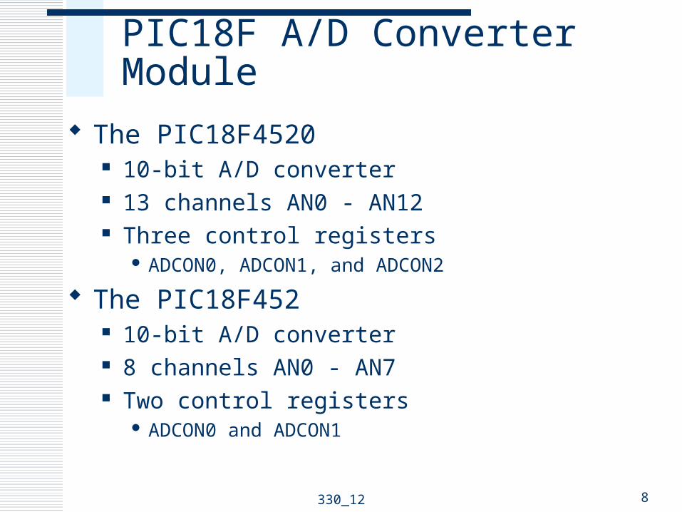
The PIC18F4520 10-bit A/D converter 13 channels AN0 - AN12 Three control registers
ADCON0, ADCON1, and ADCON2
The PIC18F452 10-bit A/D converter 8 channels AN0 - AN7 Two control registers
ADCON0 and ADCON1
8330_12

PIC18F4520 A/D Converter
9330_12
A/D Control Register0
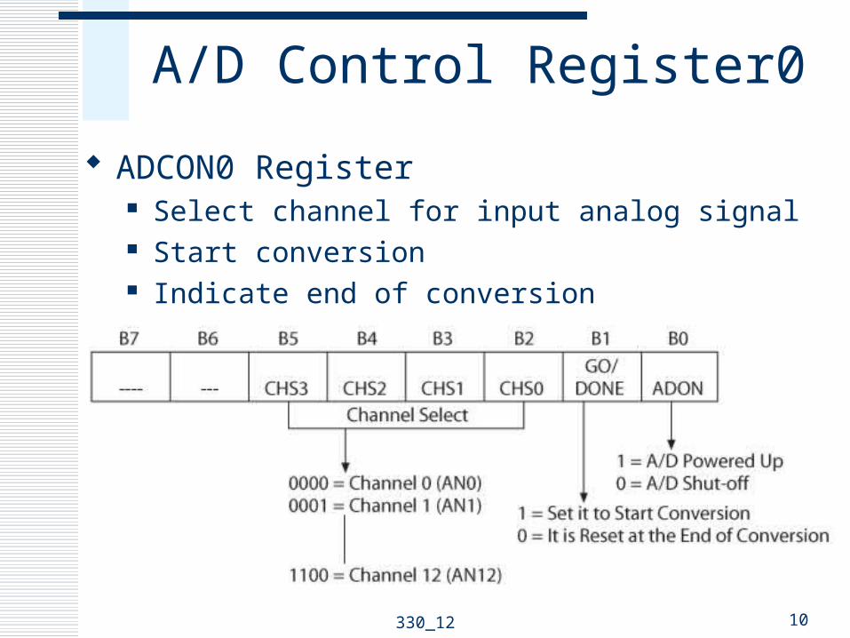
ADCON0 Register Select channel for input analog signal Start conversion Indicate end of conversion
10330_12
A/D Control Register1
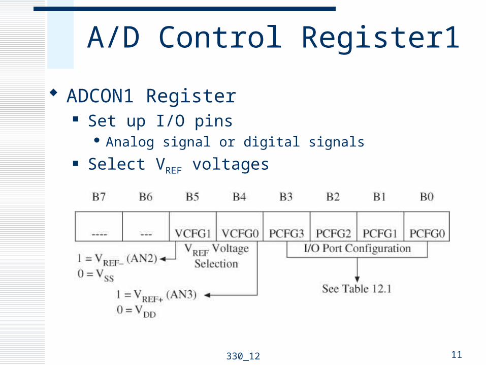
ADCON1 Register Set up I/O pins
Analog signal or digital signals Select VREF voltages
11330_12
A/D Control Register2
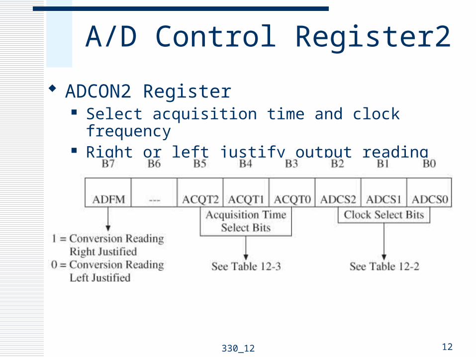
ADCON2 Register Select acquisition time and clock frequency Right or left justify output reading
12330_12
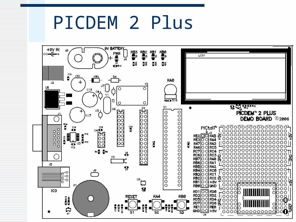
PICDEM 2 Plus
330_12 13

Digital to Analog Conversion
D/A, DAC, or D-to-A Converting discrete signals into analog values
that represent the magnitude of the input signal compared to a standard or reference Output is discrete analog steps
Increasing the resolution (number of bits)Step size is reducedApproximates a continuous analog signal
14330_12
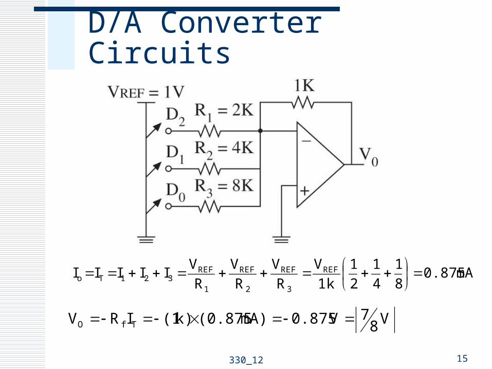
D/A Converter Circuits
15330_12
mA0.87581
41
21
k 1V
RV
RV
RVIIIII REF
3
REF
2
REF
1
REF321To
V87V0.875mA)(0.875k)(1IRV TfO

IC D/A Converters
16330_12