data projector - sony€¦ · data projector operating instructions before operating the unit,...
TRANSCRIPT

4-453-101-14 (1)
© 2012 Sony Corporation
DataProjector
Operating InstructionsBefore operating the unit, please read this manual and supplied Quick Reference Manual thoroughly and retain it for future reference.
VPL-SW536C/SW526C/SW536/SW526VPL-SX536
Not all models are available in all countries and area. Please check with your local Sony Authorized Dealer.
2
Table of Contents
Overview
Location and Function of Controls .... 4
Main Unit ..................................... 4
Connector Panel ........................... 5
Remote Commander and Control Panel Keys ................................. 6
Interactive Pen Device (VPL-SW536C/SW526C only) ........... 8
Preparation
Connecting the Projector ................... 9
Connecting a Computer ................ 9
Connecting a Video equipment ................................ 11
Connecting a microphone .......... 12
Connecting a USB memory device ...................................... 13
Connecting an External Monitor and Audio Equipment .................... 13
Projecting/Adjusting an Image
Projecting an Image ......................... 14
Adjusting the Projected image ... 16
Turning Off the Power ................ 19
Adjustments and Settings Using a Menu
Using a MENU ................................ 21
The Picture Menu ............................. 22
The Screen Menu ............................. 23
The Function Menu .......................... 27
The Operation Menu ........................ 28
The Connection/Power Menu ...........29
The Installation Menu ......................31
The Information Menu .....................32
Network
Using Network Features ...................33
Displaying the Control Window of the Projector with a Web Browser ...................................33
Confirming the Information regarding the Projector ............34
Operating the Projector from a Computer .................................34
Using the e-mail report Function ...................................35
Interactive Function
Using the Interactive Function .........37
Connecting a Computer with a USB Cable ........................................38
For Windows ...............................38
For Mac .......................................40
Presentation Function via Network
Using Presentation Function via Network .........................................42
Installing Projector Station for Network Presentation ..............42
Starting Projector Station for Network Presentation ..............42
Projecting an Image ....................43
Connection Settings ....................43
Using the Controller ...................44
Table of Contents
Displaying Images or Files Sent from a Tablet PC/Smartphone .......................44
Projecting an Image using USB Connection
Projecting an Image using USB Connection ....................................45
Starting USB Display .................45
Projecting an Image ....................45
Using the Controller ...................45
USB Media Viewer
Using USB Media Viewer ................46
Thumbnail Mode ........................47
Option Menu ...............................47
Display Mode .............................48
Option Menu ...............................48
Slideshow Mode .........................48
Option Menu ...............................49
Others
Indicators ..........................................50
Messages List ...................................51
Troubleshooting ...............................52
Replacing the Lamp .........................54
Cleaning the Air Filter .....................56
Specifications ...................................58
Projection Distance and Lens Shift Range ............................................64
Dimensions .......................................68
Index .................................................70
3Table of Contents
4
B Overview
Location and Function of Controls
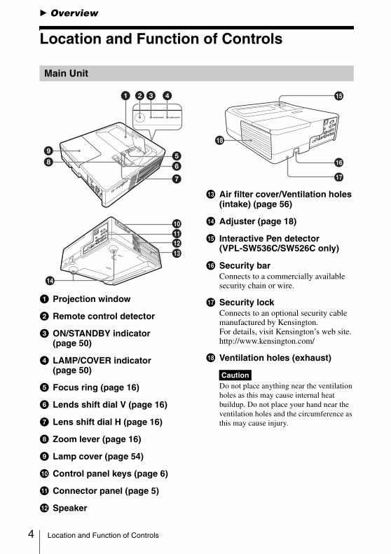
a Projection window
b Remote control detector
c ON/STANDBY indicator (page 50)
d LAMP/COVER indicator (page 50)
e Focus ring (page 16)
f Lends shift dial V (page 16)
g Lens shift dial H (page 16)
h Zoom lever (page 16)
i Lamp cover (page 54)
j Control panel keys (page 6)
k Connector panel (page 5)
l Speaker
m Air filter cover/Ventilation holes (intake) (page 56)
n Adjuster (page 18)
o Interactive Pen detector (VPL-SW536C/SW526C only)
p Security barConnects to a commercially available security chain or wire.
q Security lockConnects to an optional security cable manufactured by Kensington.For details, visit Kensington’s web site.http://www.kensington.com/
r Ventilation holes (exhaust)
Do not place anything near the ventilation holes as this may cause internal heat buildup. Do not place your hand near the ventilation holes and the circumference as this may cause injury.
Main Unit
1 23 4
598 6
7
0qaqsqd
qf
Caution
Location and Function of Controls
Overview
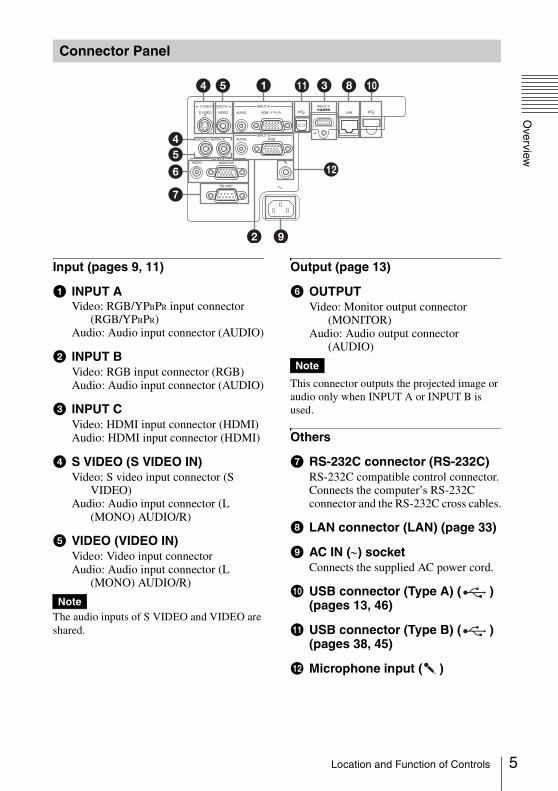
Input (pages 9, 11)
a INPUT AVideo: RGB/YPBPR input connector
(RGB/YPBPR)Audio: Audio input connector (AUDIO)
b INPUT BVideo: RGB input connector (RGB)Audio: Audio input connector (AUDIO)
c INPUT CVideo: HDMI input connector (HDMI)Audio: HDMI input connector (HDMI)
d S VIDEO (S VIDEO IN)Video: S video input connector (S
VIDEO)Audio: Audio input connector (L
(MONO) AUDIO/R)
e VIDEO (VIDEO IN)Video: Video input connectorAudio: Audio input connector (L
(MONO) AUDIO/R)
The audio inputs of S VIDEO and VIDEO are shared.
Output (page 13)
f OUTPUTVideo: Monitor output connector
(MONITOR)Audio: Audio output connector
(AUDIO)
This connector outputs the projected image or audio only when INPUT A or INPUT B is used.
Others
g RS-232C connector (RS-232C)RS-232C compatible control connector.Connects the computer’s RS-232C connector and the RS-232C cross cables.
h LAN connector (LAN) (page 33)
i AC IN (∼) socketConnects the supplied AC power cord.
j USB connector (Type A) ( ) (pages 13, 46)
k USB connector (Type B) ( ) (pages 38, 45)
l Microphone input ( )
Connector Panel
54
45
7
6
1
2 9
8 q;3
qs
qa
Note
Note
5Location and Function of Controls
6
Remote Commander
Control Panel Keys
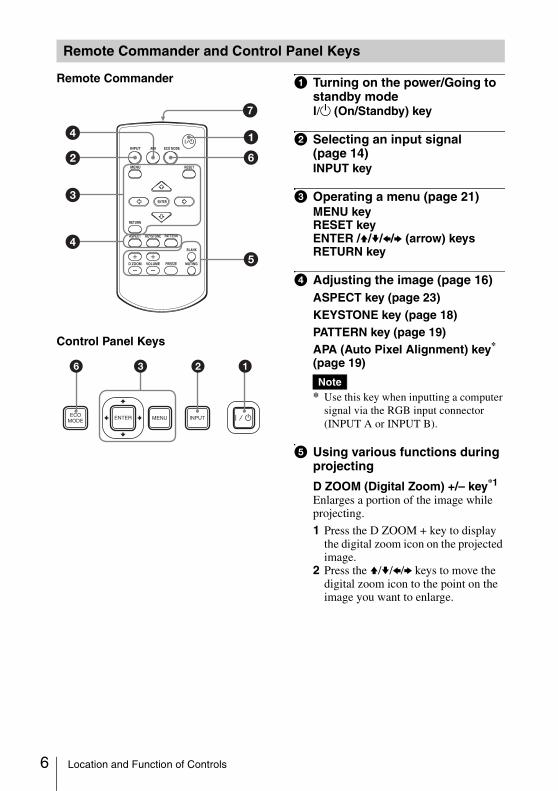
a Turning on the power/Going to standby mode?/1 (On/Standby) key
b Selecting an input signal (page 14)INPUT key
c Operating a menu (page 21)MENU keyRESET keyENTER /V/v/B/b (arrow) keysRETURN key
d Adjusting the image (page 16)ASPECT key (page 23)KEYSTONE key (page 18)PATTERN key (page 19)APA (Auto Pixel Alignment) key* (page 19)
* Use this key when inputting a computer signal via the RGB input connector (INPUT A or INPUT B).
e Using various functions during projecting
D ZOOM (Digital Zoom) +/– key*1
Enlarges a portion of the image while projecting.
1 Press the D ZOOM + key to display the digital zoom icon on the projected image.
2 Press the V/v/B/b keys to move the digital zoom icon to the point on the image you want to enlarge.
Remote Commander and Control Panel Keys
2
3
45
6
14
7
INPUT
MENU
APA ECO MODE
RETURN
ASPECT
D ZOOM
KEYSTONE
ENTER
VOLUME
PATTERN
FREEZE
BLANK
MUTING
RESET
1236Note
Location and Function of Controls

Overview
3 Press the D ZOOM + key or the D ZOOM – key repeatedly to change the enlargement ratio. The image can be enlarged up to 4 times.
Press the RESET key to restore the previous image.
BLANK keyCuts off the projected image temporarily. Press again to restore the previous image. Picture muting helps reduce power consumption.
MUTING keyMutes the audio output temporarily. Press again to restore the previous volume.
VOLUME +/– keyAdjusts the volume output.
FREEZE key*2
Pauses a projected image. Press again to restore the image.
*1: Use this key when inputting a computer signal. But it may not be used depending on the resolution of the input signal.
*2: Use this key when inputting a computer signal.You cannot use this key when “Type A USB”, “Type B USB” or “Network” is selected as the input.
f Setting the energy–saving mode easily
ECO MODE keyEnergy-saving mode can be set easily. Energy-saving mode consists of “Lamp Mode,” “With No Input,” “With Static Signal,” “Standby Mode.”
1 Press the ECO MODE key to display the ECO Mode menu.
2 Press the V/v key or ECO MODE key to select ECO or User mode.ECO: Sets each mode to the optimum
energy-saving value.Lamp Mode: LowWith No Input: StandbyWith Static Signal: Lamp DimmingStandby Mode: Low
User: Sets each item of the ECO mode menu as you desire (go to step 3).
3 Select “User” then press the b key.The setting items appear.
4 Press the V/v key to select the item then press the ENTER key.
5 Press the V/v key to select the setting value.
6 Press the ENTER key.The screen returns to the User screen.
For details on ECO Mode settings, see “Lamp Mode”, “With No Input”, “With Static Signal” and “Standby Mode” on the Connection/Power menu (page 29).
Others
g Infrared transmitter
About remote commander operation• Direct the remote commander toward the
remote control detector.• The shorter the distance between the
remote commander and the projector is, the wider the angle within which the remote commander can control the projector becomes.
• Make sure that nothing obstructs the infrared beam between the remote commander and the remote control detector on the projector.
Notes
RETURN
ECOUser
ECO Mode
:Sel :Back
ECO Mode Menu
RETURN
Lamp Mode High
AUTO POWER SAVING
Standby Mode
OffWith No InputLamp DimmingWith Static Signal
Standard
User
:Sel :Set :Back
7Location and Function of Controls
8
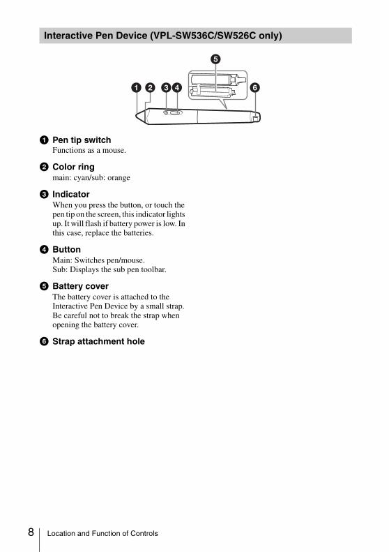
a Pen tip switchFunctions as a mouse.
b Color ringmain: cyan/sub: orange
c IndicatorWhen you press the button, or touch the pen tip on the screen, this indicator lights up. It will flash if battery power is low. In this case, replace the batteries.
d ButtonMain: Switches pen/mouse.Sub: Displays the sub pen toolbar.
e Battery coverThe battery cover is attached to the Interactive Pen Device by a small strap. Be careful not to break the strap when opening the battery cover.
f Strap attachment hole
Interactive Pen Device (VPL-SW536C/SW526C only)
1 2 34 6
5
Location and Function of Controls

Preparation
B Preparation
Connecting the Projector
• Make sure all the equipment is powered off when connecting the projector.• Use the proper cables for each connection.• Insert the cable plugs firmly; Loose connections may reduce performance of picture signals or
cause a malfunction. When pulling out a cable, be sure to grip it by the plug, not the cable itself.• For more information, refer also to the instruction manuals of the equipment you are connecting.• Use a no-resistance audio cable.
Connection with a computer is explained for each input signal.
INPUT A/INPUT B
It is recommended that you set the resolution of your computer to 1280 × 800 pixels (VPL-SW536C/SW526C/SW536/SW526) or 1024 × 768 pixels (VPL-SX536) for the external monitor.
INPUT C
• Use HDMI-compatible equipment and cable(s) that have an HDMI logo on them.• The HDMI connector of this projector is not compatible with DSD (Direct Stream Digital) Signal
or CEC (Consumer Electronics Control) Signal.
Notes
Connecting a Computer
For connecting a computer with an RGB output connector.
RGB output connector
Audio output connector
Mini D-sub 15-pin cable (not supplied)
Computer
Audio cable (Stereo mini plug) (not supplied)
Note
Notes
For connecting a computer with an HDMI output connector.
HDMI output connector
HDMI cable (not supplied)
Computer
9Connecting the Projector
10
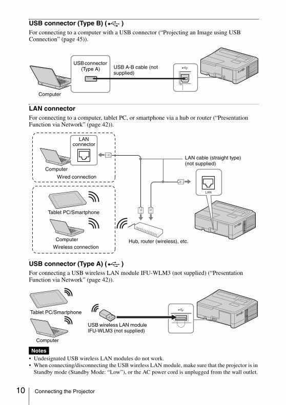
USB connector (Type B) ( )For connecting to a computer with a USB connector (“Projecting an Image using USB Connection” (page 45)).
LAN connectorFor connecting to a computer, tablet PC, or smartphone via a hub or router (“Presentation Function via Network” (page 42)).
USB connector (Type A) ( )For connecting a USB wireless LAN module IFU-WLM3 (not supplied) (“Presentation Function via Network” (page 42)).
• Undesignated USB wireless LAN modules do not work.• When connecting/disconnecting the USB wireless LAN module, make sure that the projector is in
Standby mode (Standby Mode: “Low”), or the AC power cord is unplugged from the wall outlet.
USB A-B cable (not supplied)
Computer
USB connector (Type A)
Notes
LAN cable (straight type)(not supplied)
Computer
LAN connector
Wired connection
Tablet PC/Smartphone
Computer
Wireless connectionHub, router (wireless), etc.
USB wireless LAN module IFU-WLM3 (not supplied)
Tablet PC/Smartphone
Computer
Connecting the Projector

Preparation
• When wirelessly connecting a tablet PC/smartphone to the projector via USB wireless LAN module IFU-WLM3 (not supplied), set “Access Point Setup” to “Manual” in the projector’s “WLAN Settings” (page 29).
Connections with a VHS video deck, DVD player, or BD player are explained for each input signal.
S VIDEO INFor connecting video equipment with an S-video output connector.
VIDEO IN For connecting video equipment with a video output connector.
Connecting a Video equipment
S video cable (not supplied)
Audio cable (Phono plug × 2) (not supplied)
S video output connector
Audio output connector
Video equipment
Video cable (not supplied)
Audio cable (Phono plug × 2) (not supplied)
Video output connector
Audio output connectorVideo equipment
11Connecting the Projector
12
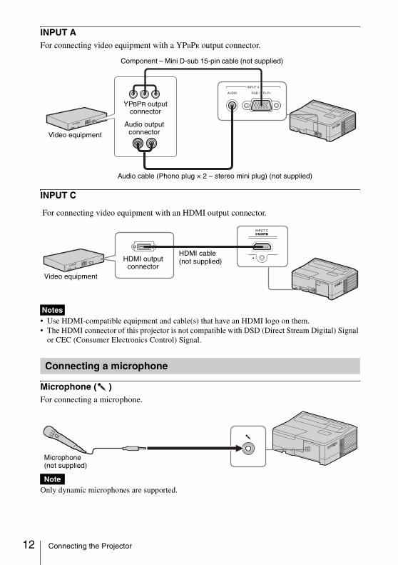
INPUT AFor connecting video equipment with a YPBPR output connector.
INPUT C
• Use HDMI-compatible equipment and cable(s) that have an HDMI logo on them.• The HDMI connector of this projector is not compatible with DSD (Direct Stream Digital) Signal
or CEC (Consumer Electronics Control) Signal.
Microphone ( )For connecting a microphone.
Only dynamic microphones are supported.
Notes
Connecting a microphone
Note
Component – Mini D-sub 15-pin cable (not supplied)
Audio cable (Phono plug × 2 – stereo mini plug) (not supplied)
Video equipment
YPBPR output connector
Audio output connector
Video equipment
HDMI cable (not supplied)HDMI output
connector
For connecting video equipment with an HDMI output connector.
Microphone (not supplied)
Connecting the Projector
Preparation
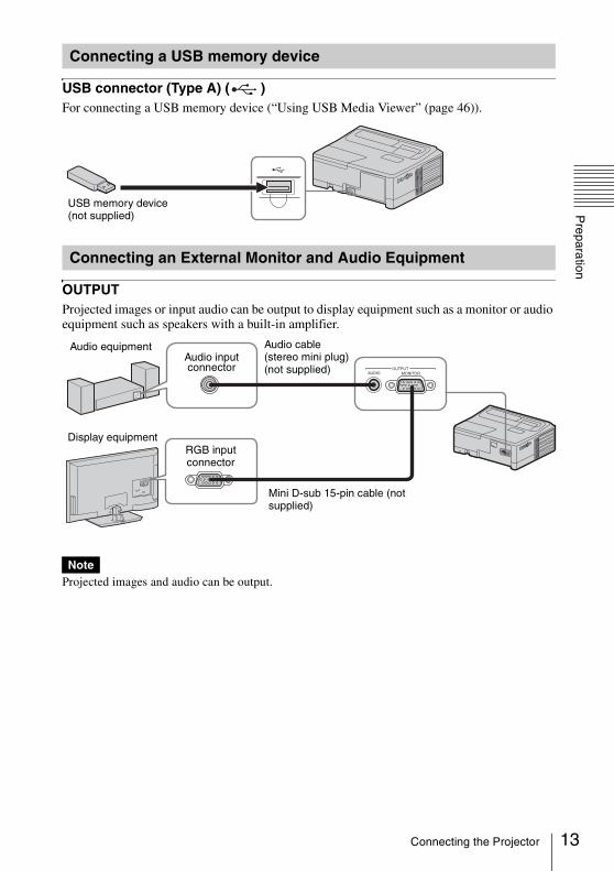
USB connector (Type A) ( )For connecting a USB memory device (“Using USB Media Viewer” (page 46)).
OUTPUTProjected images or input audio can be output to display equipment such as a monitor or audio equipment such as speakers with a built-in amplifier.
Projected images and audio can be output.
Connecting a USB memory device
Connecting an External Monitor and Audio Equipment
USB memory device (not supplied)
Note
Audio cable (stereo mini plug) (not supplied)
Audio input connector
RGB input connector
Mini D-sub 15-pin cable (not supplied)
Audio equipment
Display equipment
13Connecting the Projector
14
B Projecting/Adjusting an Image
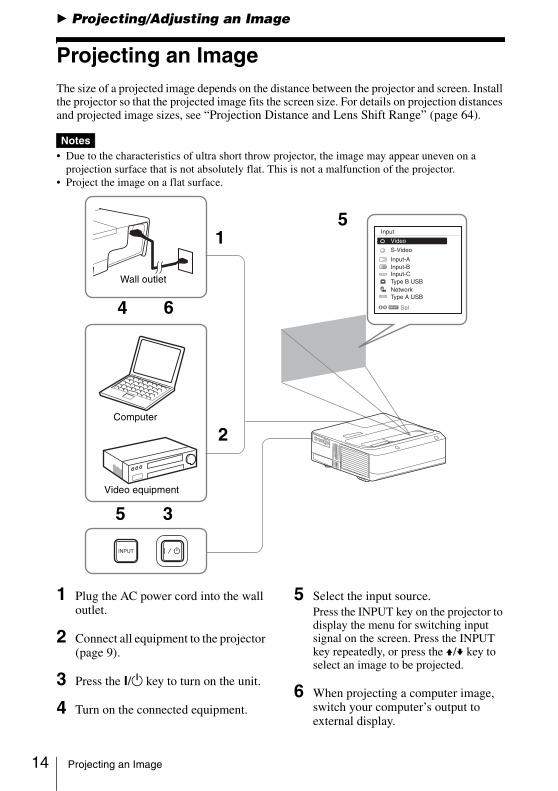
Projecting an ImageThe size of a projected image depends on the distance between the projector and screen. Install the projector so that the projected image fits the screen size. For details on projection distances and projected image sizes, see “Projection Distance and Lens Shift Range” (page 64).
• Due to the characteristics of ultra short throw projector, the image may appear uneven on a projection surface that is not absolutely flat. This is not a malfunction of the projector.
• Project the image on a flat surface.
1 Plug the AC power cord into the wall outlet.
2 Connect all equipment to the projector (page 9).
3 Press the ?/1 key to turn on the unit.
4 Turn on the connected equipment.
5 Select the input source.Press the INPUT key on the projector to display the menu for switching input signal on the screen. Press the INPUT key repeatedly, or press the V/v key to select an image to be projected.
6 When projecting a computer image, switch your computer’s output to external display.
Notes
Computer
Video equipment
Wall outlet
1
2
3
4
5
6
5
Projecting an Image
Projecting/A
djusting an Image
The method to switch the output varies depending on the type of computer.
(Example)
To project image files stored in a USB memory device, see “USB Media Viewer” (page 46). To project an image using USB Connection, see “Projecting an Image using USB Connection” (page 45). To use Presentation Function via Network, see “Presentation Function via Network” (page 42).
7 Adjust the focus, size and position of the projected image (page 16).
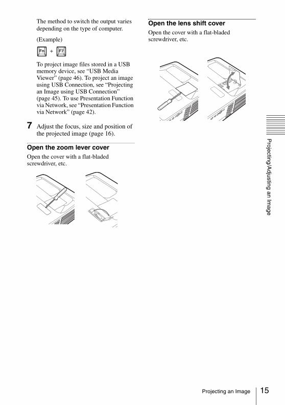
Open the zoom lever coverOpen the cover with a flat-bladed screwdriver, etc.
Open the lens shift coverOpen the cover with a flat-bladed screwdriver, etc.
+
15Projecting an Image
16
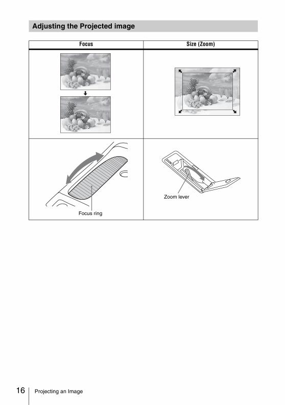
Adjusting the Projected image
Focus Size (Zoom)
Focus ring
Zoom lever
Projecting an Image
Projecting/A
djusting an Image
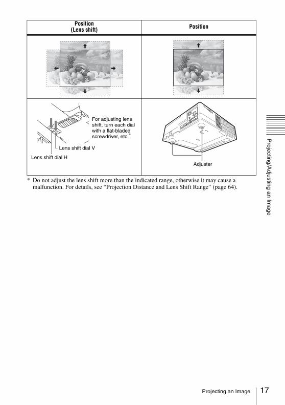
* Do not adjust the lens shift more than the indicated range, otherwise it may cause a malfunction. For details, see “Projection Distance and Lens Shift Range” (page 64).
Position(Lens shift) Position
Lens shift dial H
Lens shift dial V
For adjusting lens shift, turn each dial with a flat-bladed screwdriver, etc.*
Adjuster
17Projecting an Image
18
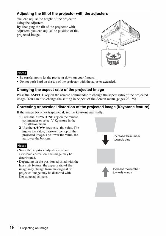
Adjusting the tilt of the projector with the adjustersYou can adjust the height of the projector using the adjusters.By changing the tilt of the projector with adjusters, you can adjust the position of the projected image.
• Be careful not to let the projector down on your fingers.• Do not push hard on the top of the projector with the adjuster extended.
Changing the aspect ratio of the projected imagePress the ASPECT key on the remote commander to change the aspect ratio of the projected image. You can also change the setting in Aspect of the Screen menu (pages 23, 25).
Correcting trapezoidal distortion of the projected image (Keystone feature) If the image becomes trapezoidal, set the keystone manually.
1 Press the KEYSTONE key on the remote commander or select V Keystone in the Installation menu.
2 Use the V/v/B/b keys to set the value. The higher the value, narrower the top of the projected image. The lower the value, the narrower the bottom.
• Since the Keystone adjustment is an electronic correction, the image may be deteriorated.
• Depending on the position adjusted with the lens shift feature, the aspect ratio of the image may change from the original or projected image may be distorted with Keystone adjustment.
Notes
Notes
Increase the number towards plus
Increase the number towards minus
Projecting an Image
Projecting/A
djusting an Image
Displaying a patternYou can display a pattern for adjusting the projected image or a grid pattern with the PATTERN key on the remote commander. Press the PATTERN key again to restore the previous image. You can use a grid pattern as a guide to write text or to draw lines and shapes on the whiteboard or blackboard without using a computer.
You cannot use this key when “Type A USB”, “Type B USB” or “Network” is selected as the input.
Automatically adjusts Phase, Pitch and Shift of projected image while a signal is input from a computer (APA (Auto Pixel Alignment))Press the APA key on the remote commander. Press again to cancel adjusting during the setting.You can also set APA in the Screen Menu (page 24). If Smart APA in the Function menu is set to “On”, executes APA automatically when a signal is input (page 27).
1 Press the ?/1 key on the unit or the remote commander.The projector starts shutdown and turns off. If you press the ?/1 key within 10 seconds again, shutdown is cancelled.
Do not turn off the projector soon after the lamp lights. It may cause a malfunction of the lamp(does not light ,etc.).
2 Unplug the AC power cord from the wall outlet.
To turn off without displaying confirmation messagePress and hold the ?/1 key on the unit for a few seconds (page 51).
Note
Turning Off the Power
Note
19Projecting an Image
20
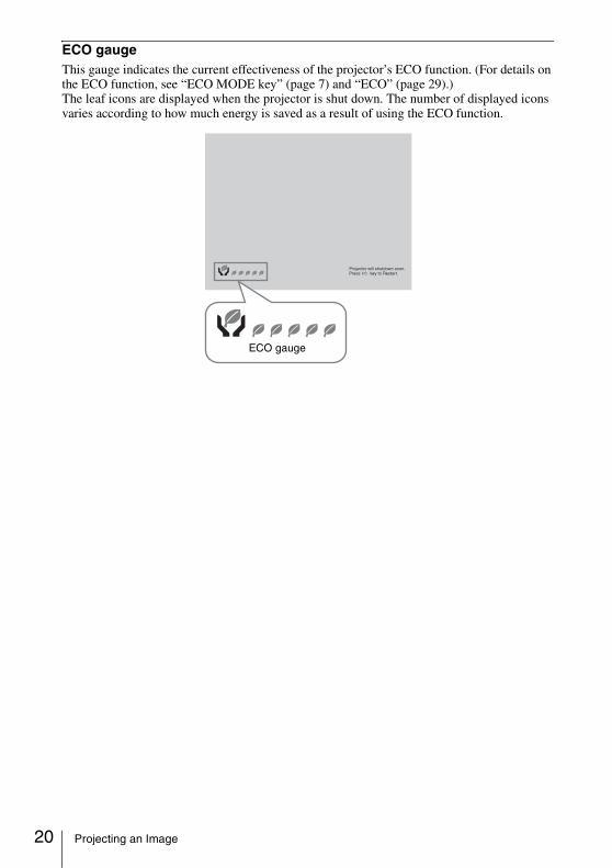
ECO gaugeThis gauge indicates the current effectiveness of the projector’s ECO function. (For details on the ECO function, see “ECO MODE key” (page 7) and “ECO” (page 29).) The leaf icons are displayed when the projector is shut down. The number of displayed icons varies according to how much energy is saved as a result of using the ECO function.
ECO gauge
Projecting an Image

Adjustm
ents and Settings U
sing a Menu
B Adjustments and Settings Using a Menu
Using a MENU
The menu displays used for the explanation below may be different depending on the model you are using.
1 Press the MENU key to display the menu.
2 Select the setting menu. Use the V/v key to select the setting menu then press the b key or ENTER key.
3 Select the setting item.Use the V/v key to select the setting menu then press the b key or ENTER key.To return to the selection screen of the setting menu, press the B or RETURN key.
4 Make the setting or adjustment for the selected item. The setting method varies, depending on the setting item.If the next menu window is displayed, select the item according to the
operations in step 3 and then press the ENTER key to register the setting.To return to the selection screen of the setting items, press the B or RETURN key. You can press the RESET key to reset an item to its factory setting value to aid setting.
Using a pop-up menuPress the V/v/B/b key to select an item.A selected item takes effect immediately, except “Language”, which will take effect after you press the ENTER key.
Using the setting menu Press the V/v key to select the item. A selected item takes effect immediately. The previous screen is restored.Using the adjustment menuTo increase the value, press the V/b key and to decrease the number, press the v/B key. A selected item takes effect immediately. The previous screen is restored.
5 Press the MENU key to clear the menu.The menu disappears automatically if no operation is performed.
Note
Picture Mode StandardResetContrastBrightnessColorHueColor Temp.SharpnessExpert Setting
:Sel :Set :Back
Picture
Low
Setting menu
80505050
50
Picture Mode StandardResetContrastBrightnessColorHueColor Temp.SharpnessExpert Setting
:Sel :Set :Back
Picture
Low
Setting items
RETURN
Picture ModeDynamicStandard
:Back:Sel
CinemaGameBlackboardPresentation
Adjust Back
Contrast
21Using a MENU
22
The Picture MenuThe Picture is used to adjust the picture for each input signal.
*1: When a computer signal is input, this option is available.*2: When a video signal is input, this option is available.*3: When “Picture Mode” is set to the item other than “Presentation” or “Blackboard,” this option
is available.*4: When the signal without color burst signal is input, this option is unavailable.*5: When an analog TV signal is input, this option may not available, depending on the color system.*6: When “Picture Mode” is set to “Blackboard,” this option is unavailable.*7: The settings in the Picture return to their factory defaults, except for Picture Mode.
Items Item descriptions
Picture Mode Dynamic: Emphasizes the contrast to produce a dynamic and vivid picture.Standard: Provides an image which is natural and well balanced.Presentation*1: Provides a bright image, suitable for presentations.Blackboard: Provides an image suitable for displaying on a blackboard.Game: Provides an image suitable for viewing games.Cinema: Provides an image suitable for viewing movies.
Reset*7 Resets the factory setting.
Contrast The higher the value, the greater the contrast. The lower the value, the lower the contrast.
Brightness The higher the value, the brighter the picture. The lower the value, the darker the picture.
Color*2 *4 The higher the value, the greater the intensity. The lower the value, the lower the intensity.
Hue*2 *4 *5 The higher the value, the more greenish the picture becomes. The lower the value, the more reddish the picture becomes.
Color Temp.*3 High/Middle/Low: The higher the value, the more bluish the picture. The lower the value, the more reddish the picture.
Sharpness*2 The higher the value, the sharper the picture. The lower the value, the softer the picture.
Expert Setting
Film Mode*2 *6
Auto: Precisely reproduces a film image to match the appearance of the original film source. Set to “Auto” in most cases.Off: Select this mode if the image outline appears jagged.
Gamma Mode*1 *6
Graphics1: Gamma correction to make halftones brighter. This setting issuitable when projecting highly colorful images, such as photos, in a brightplace.Graphics2: Gamma correction to improve the reproduction of halftones.Highly colorful images, such as photos, can be reproduced in natural tones.Text: Improves back and white contrast. Suitable for images with lots of text content.
Notes
The Picture Menu
Adjustm
ents and Settings U
sing a Menu
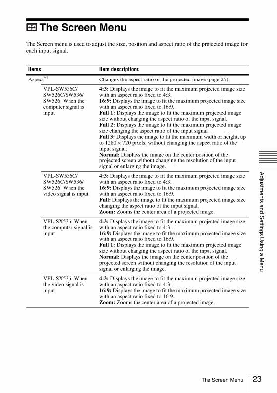
The Screen MenuThe Screen menu is used to adjust the size, position and aspect ratio of the projected image for each input signal.
Items Item descriptions
Aspect*1 Changes the aspect ratio of the projected image (page 25).
VPL-SW536C/SW526C/SW536/SW526: When the computer signal is input
4:3: Displays the image to fit the maximum projected image size with an aspect ratio fixed to 4:3.16:9: Displays the image to fit the maximum projected image size with an aspect ratio fixed to 16:9.Full 1: Displays the image to fit the maximum projected image size without changing the aspect ratio of the input signal.Full 2: Displays the image to fit the maximum projected image size changing the aspect ratio of the input signal.Full 3: Displays the image to fit the maximum width or height, up to 1280 × 720 pixels, without changing the aspect ratio of the input signal.Normal: Displays the image on the center position of the projected screen without changing the resolution of the input signal or enlarging the image.
VPL-SW536C/SW526C/SW536/SW526: When the video signal is input
4:3: Displays the image to fit the maximum projected image size with an aspect ratio fixed to 4:3.16:9: Displays the image to fit the maximum projected image size with an aspect ratio fixed to 16:9.Full: Displays the image to fit the maximum projected image size changing the aspect ratio of the input signal.Zoom: Zooms the center area of a projected image.
VPL-SX536: When the computer signal is input
4:3: Displays the image to fit the maximum projected image size with an aspect ratio fixed to 4:3.16:9: Displays the image to fit the maximum projected image size with an aspect ratio fixed to 16:9.Full 1: Displays the image to fit the maximum projected image size without changing the aspect ratio of the input signal.Normal: Displays the image on the center position of the projected screen without changing the resolution of the input signal or enlarging the image.
VPL-SX536: When the video signal is input
4:3: Displays the image to fit the maximum projected image size with an aspect ratio fixed to 4:3.16:9: Displays the image to fit the maximum projected image size with an aspect ratio fixed to 16:9.Zoom: Zooms the center area of a projected image.
23The Screen Menu
24
*1: • Note that if the projector is used for profit or for public viewing, modifying the original picture by switching to the aspect mode may constitute an infringement of the rights of authors or producers, which are legally protected.
• Depending on the input signal, setting items for aspect ratio or some other setting items cannot be set in some cases, or changing the aspect ratio setting may have no effect.
• A part of the image may be displayed in black, depending on the setting item.*2: Available when a computer signal is input from the RGB input connector (INPUT A/INPUT B).*3: If the projected image includes large amount of black portion around it, the APA function will
not work properly and a part of the image may not be displayed on the screen and also optimum image cannot be obtained, depending on the type of input signal. In this case, adjust the “Phase,” “Pitch,” and “Shift” items manually.
*4: Available when a computer or a video signal is input from the RGB/YPBPR input connector (INPUT A).
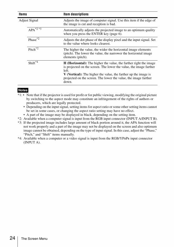
Adjust Signal Adjusts the image of computer signal. Use this item if the edge of the image is cut and reception is bad.
APA*2 *3 Automatically adjusts the projected image to an optimum quality when you press the ENTER key (page 6).
Phase*2 Adjusts the dot phase of the display pixel and the input signal. Set to the value where looks clearest.
Pitch*2 The higher the value, the wider the horizontal image elements (pitch). The lower the value, the narrower the horizontal image elements (pitch).
Shift*4 H (Horizontal): The higher the value, the farther right the image is projected on the screen. The lower the value, the image farther left.V (Vertical): The higher the value, the farther up the image is projected on the screen. The lower the value, the image farther down.
Notes
Items Item descriptions
The Screen Menu
Adjustm
ents and Settings U
sing a Menu
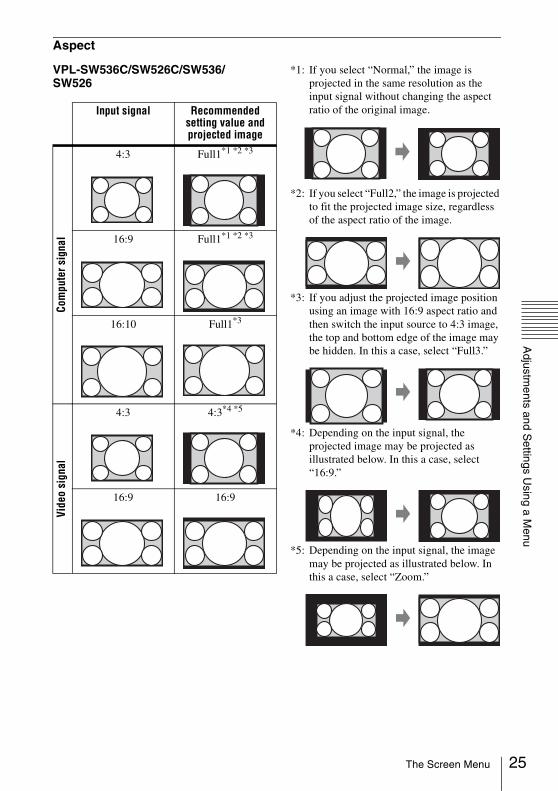
Aspect
VPL-SW536C/SW526C/SW536/SW526
*1: If you select “Normal,” the image is projected in the same resolution as the input signal without changing the aspect ratio of the original image.
*2: If you select “Full2,” the image is projected to fit the projected image size, regardless of the aspect ratio of the image.
*3: If you adjust the projected image position using an image with 16:9 aspect ratio and then switch the input source to 4:3 image, the top and bottom edge of the image may be hidden. In this a case, select “Full3.”
*4: Depending on the input signal, the projected image may be projected as illustrated below. In this a case, select “16:9.”
*5: Depending on the input signal, the image may be projected as illustrated below. In this a case, select “Zoom.”
Input signal Recommended setting value and projected image
Com
pute
r sig
nal
4:3 Full1*1 *2 *3
16:9 Full1*1 *2 *3
16:10 Full1*3
Vide
o si
gnal
4:3 4:3*4 *5
16:9 16:9
25The Screen Menu
26
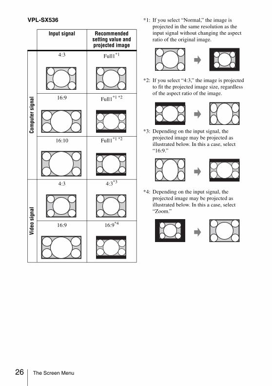
VPL-SX536 *1: If you select “Normal,” the image is projected in the same resolution as the input signal without changing the aspect ratio of the original image.
*2: If you select “4:3,” the image is projected to fit the projected image size, regardless of the aspect ratio of the image.
*3: Depending on the input signal, the projected image may be projected as illustrated below. In this a case, select “16:9.”
*4: Depending on the input signal, the projected image may be projected as illustrated below. In this a case, select “Zoom.”
Input signal Recommended setting value and projected image
Com
pute
r sig
nal
4:3 Full1*1
16:9 Full1*1 *2
16:10 Full1*1 *2
Vide
o si
gnal
4:3 4:3*3
16:9 16:9*4
The Screen Menu
Adjustm
ents and Settings U
sing a Menu
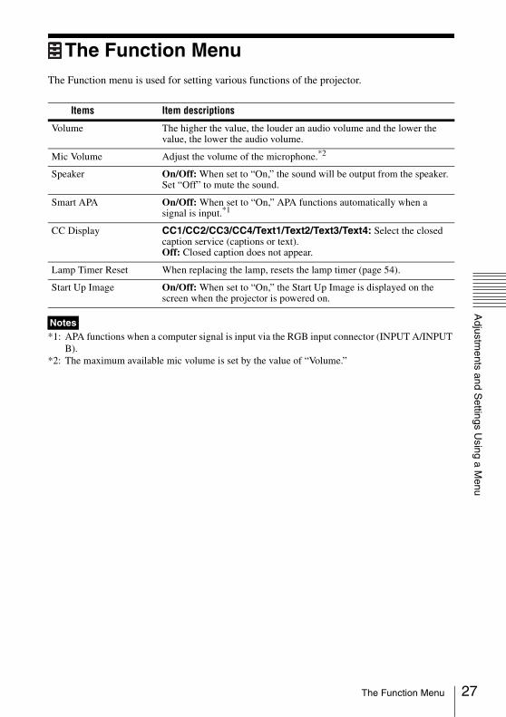
The Function MenuThe Function menu is used for setting various functions of the projector.
*1: APA functions when a computer signal is input via the RGB input connector (INPUT A/INPUT B).
*2: The maximum available mic volume is set by the value of “Volume.”
Items Item descriptions
Volume The higher the value, the louder an audio volume and the lower the value, the lower the audio volume.
Mic Volume Adjust the volume of the microphone.*2
Speaker On/Off: When set to “On,” the sound will be output from the speaker. Set “Off” to mute the sound.
Smart APA On/Off: When set to “On,” APA functions automatically when a signal is input.*1
CC Display CC1/CC2/CC3/CC4/Text1/Text2/Text3/Text4: Select the closed caption service (captions or text).Off: Closed caption does not appear.
Lamp Timer Reset When replacing the lamp, resets the lamp timer (page 54).
Start Up Image On/Off: When set to “On,” the Start Up Image is displayed on the screen when the projector is powered on.
Notes
27The Function Menu
28
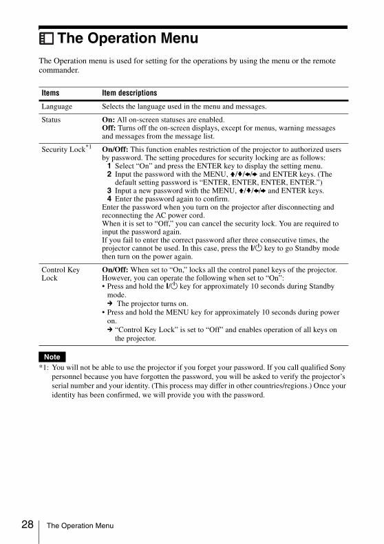
The Operation MenuThe Operation menu is used for setting for the operations by using the menu or the remote commander.
*1: You will not be able to use the projector if you forget your password. If you call qualified Sony personnel because you have forgotten the password, you will be asked to verify the projector’s serial number and your identity. (This process may differ in other countries/regions.) Once your identity has been confirmed, we will provide you with the password.
Items Item descriptions
Language Selects the language used in the menu and messages.
Status On: All on-screen statuses are enabled.Off: Turns off the on-screen displays, except for menus, warning messages and messages from the message list.
Security Lock*1 On/Off: This function enables restriction of the projector to authorized users by password. The setting procedures for security locking are as follows:
1 Select “On” and press the ENTER key to display the setting menu.2 Input the password with the MENU, V/v/B/b and ENTER keys. (The
default setting password is “ENTER, ENTER, ENTER, ENTER.”)3 Input a new password with the MENU, V/v/B/b and ENTER keys.4 Enter the password again to confirm.
Enter the password when you turn on the projector after disconnecting and reconnecting the AC power cord.When it is set to “Off,” you can cancel the security lock. You are required to input the password again.If you fail to enter the correct password after three consecutive times, the projector cannot be used. In this case, press the ?/1 key to go Standby mode then turn on the power again.
Control Key Lock
On/Off: When set to “On,” locks all the control panel keys of the projector. However, you can operate the following when set to “On”:• Press and hold the ?/1 key for approximately 10 seconds during Standby
mode.c The projector turns on.
• Press and hold the MENU key for approximately 10 seconds during power on.c “Control Key Lock” is set to “Off” and enables operation of all keys on
the projector.
Note
The Operation Menu
Adjustm
ents and Settings U
sing a Menu
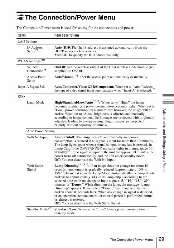
The Connection/Power MenuThe Connection/Power menu is used for setting for the connections and power.
Items Item descriptions
LAN Settings
IP Address Setup*9
Auto (DHCP): The IP address is assigned automatically from the DHCP server such as a router.Manual: To specify the IP Address manually.
WLAN Settings*10
WLAN Connection*8
On/Off: Set the wireless output of the USB wireless LAN module (not supplied) to On/Off.
Access Point Setup
Auto/Manual *11: Set the access point automatically or manually.
Input-A Signal Sel. Auto/Computer/Video GBR/Component: When set to “Auto,” selects the type of video signal input automatically when “Input-A” is selected. *1
ECO
Lamp Mode High/Standard/Low/Auto*5 *7: When set to “High,” the image becomes brighter, and power consumption becomes higher. When set to “Low,” power consumption is minimized; however, the image will be darker. When set to “Auto,” brightness is adjusted automatically according to image content. Dark images are projected with brightness adjusted, leading to energy-saving. Bright images are projected brightly, without adjusting brightness.
Auto Power Saving
With No Input Lamp Cutoff: The lamp turns off automatically and power consumption is reduced if no signal is input for more than 10 minutes.The lamp lights again when a signal is input or any key is pressed. In Lamp Cutoff, the ON/STANDBY indicator lights in orange. (page 50)Standby*6: If no signal is input to the unit for approx. 10 minutes, the power turns off automatically, and the unit enters standby mode.Off: You can deactivate the With No Input.
With Static Signal
Lamp Dimming*4 *5 *7: If an image does not change for about 10 seconds, lamp output is gradually reduced (approximately 10% to 15%*3) from that set in the Lamp Mode. Automatically the lamp slowly darkens to approximately 30% of its lamp output according to the selected time (with no change to input signal) “5,” “10,” “15,” “20” minutes or “Demo.,” While dimming the lamp, the message “Lamp Dimming” appears. If you select “Demo.,” the image will start to darken about 40 seconds later. When any change in signal is detected, or an operation (remote control or control panel) is performed, normal brightness is restored.Off: You can deactivate the With Static Signal.
Standby Mode*2 Standard/Low: When set to “Low,” lowers power consumption in Standby mode.
29The Connection/Power Menu
30
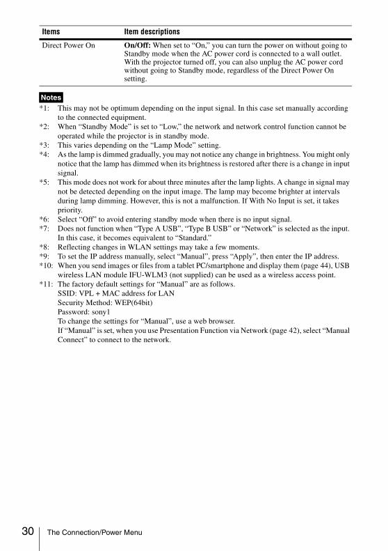
*1: This may not be optimum depending on the input signal. In this case set manually according to the connected equipment.
*2: When “Standby Mode” is set to “Low,” the network and network control function cannot be operated while the projector is in standby mode.
*3: This varies depending on the “Lamp Mode” setting. *4: As the lamp is dimmed gradually, you may not notice any change in brightness. You might only
notice that the lamp has dimmed when its brightness is restored after there is a change in input signal.
*5: This mode does not work for about three minutes after the lamp lights. A change in signal may not be detected depending on the input image. The lamp may become brighter at intervals during lamp dimming. However, this is not a malfunction. If With No Input is set, it takes priority.
*6: Select “Off” to avoid entering standby mode when there is no input signal.*7: Does not function when “Type A USB”, “Type B USB” or “Network” is selected as the input.
In this case, it becomes equivalent to “Standard.”*8: Reflecting changes in WLAN settings may take a few moments.*9: To set the IP address manually, select “Manual”, press “Apply”, then enter the IP address.*10: When you send images or files from a tablet PC/smartphone and display them (page 44), USB
wireless LAN module IFU-WLM3 (not supplied) can be used as a wireless access point.*11: The factory default settings for “Manual” are as follows.
SSID: VPL + MAC address for LANSecurity Method: WEP(64bit)Password: sony1To change the settings for “Manual”, use a web browser.If “Manual” is set, when you use Presentation Function via Network (page 42), select “Manual Connect” to connect to the network.
Direct Power On On/Off: When set to “On,” you can turn the power on without going to Standby mode when the AC power cord is connected to a wall outlet. With the projector turned off, you can also unplug the AC power cord without going to Standby mode, regardless of the Direct Power On setting.
Notes
Items Item descriptions
The Connection/Power Menu
Adjustm
ents and Settings U
sing a Menu
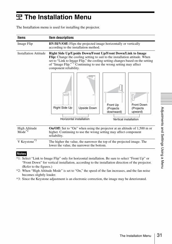
The Installation MenuThe Installation menu is used for installing the projector.
*1: Select “Link to Image Flip” only for horizontal installation. Be sure to select “Front Up” or “Front Down” for vertical installation, according to the installation direction of the projector. (Refer to the figures.)
*2: When “High Altitude Mode” is set to “On,” the speed of the fan increases, and the fan noise becomes slightly louder.
*3: Since the Keystone adjustment is an electronic correction, the image may be deteriorated.
Items Item descriptions
Image Flip HV/H/V/Off: Flips the projected image horizontally or vertically according to the installation method.
Installation Attitude Right Side Up/Upside Down/Front Up/Front Down/Link to Image Flip: Change the cooling setting to suit to the installation attitude. When set to “Link to Image Flip,” the cooling setting changes based on the setting of “Image Flip.”*1 Continuing to use the wrong setting may affect component reliability.
High Altitude Mode*2
On/Off: Set to “On” when using the projector at an altitude of 1,500 m or higher. Continuing to use the wrong setting may affect component reliability.
V Keystone*3 The higher the value, the narrower the top of the projected image. The lower the value, the narrower the bottom.
Notes
Horizontal installation
Right Side Up Upside DownFront Up(Projects downward)
Front Down(Projects upward)
Vertical installation
31The Installation Menu

32
The Information MenuThe Information menu is used to check projector status, such as total usage time of the lamp.
*1: These items may not be displayed depending on the input signal.
Items Item descriptions
Model Name Displays the model name.
Serial No. Displays the serial number.
fH/fV*1 Displays the horizontal/vertical frequency of the current input signal.
Signal Type Displays the type of the current input signal.
Lamp Timer Indicates the total usage time of a lamp.
Note
The Information Menu
Netw
ork
B NetworkUsing Network FeaturesConnection to the network allows you to operate the following features:• Checking the current status of the projector via a Web browser.• Remotely controlling the projector via a Web browser.• Receiving the e-mail report via the projector.• Making the network settings for the projector.• Displaying messages on the projected image using an application.• Supports network monitoring, control protocol (Advertisement, PJ Talk, PJ Link, AMX
DDDP [Dynamic Device Discovery Protocol], Crestron RoomView).
• The menu displays used for the explanation below may be different depending on the model you are using.
• Supported Web browsers are Internet Explorer 6/7/8/9/10.• The menu displays only in English.• If the browser of your computer is set to [Use a proxy server] when you access to the projector
from your computer, click the check mark to set accessing without using a proxy server.• To display messages, specific application Projector Station for Network Control (Version 1.1 or
later) is necessary. For download or detailed method of using Projector Station for Network Control, please access the following URL.http://pro.sony.com/bbsc/ssr/cat-projectors/resource.downloadsContact your local Sony dealer for detailed information of Projector Station for Network Control.
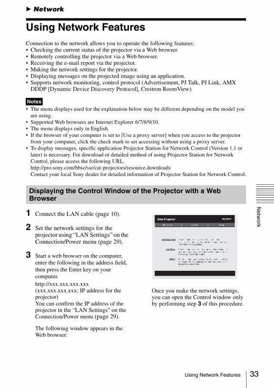
1 Connect the LAN cable (page 10).
2 Set the network settings for the projector using “LAN Settings” on the Connection/Power menu (page 29).
3 Start a web browser on the computer, enter the following in the address field, then press the Enter key on your computer.http://xxx.xxx.xxx.xxx(xxx.xxx.xxx.xxx: IP address for the projector)You can confirm the IP address of the projector in the “LAN Settings” on the Connection/Power menu (page 29).
The following window appears in the Web browser:
Once you make the network settings, you can open the Control window only by performing step 3 of this procedure.
Notes
Displaying the Control Window of the Projector with a Web Browser
33Using Network Features
34
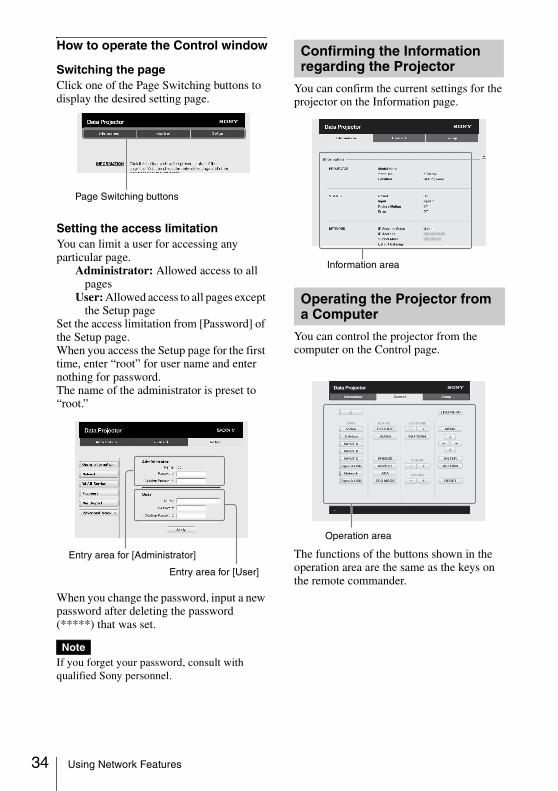
How to operate the Control window
Switching the pageClick one of the Page Switching buttons to display the desired setting page.
Setting the access limitationYou can limit a user for accessing any particular page.
Administrator: Allowed access to all pages
User: Allowed access to all pages except the Setup page
Set the access limitation from [Password] of the Setup page. When you access the Setup page for the first time, enter “root” for user name and enter nothing for password.The name of the administrator is preset to “root.”
When you change the password, input a new password after deleting the password (*****) that was set.
If you forget your password, consult with qualified Sony personnel.
You can confirm the current settings for the projector on the Information page.
You can control the projector from the computer on the Control page.
The functions of the buttons shown in the operation area are the same as the keys on the remote commander.
Note
Page Switching buttons
Entry area for [Administrator]
Entry area for [User]
Confirming the Information regarding the Projector
Operating the Projector from a Computer
Information area
Operation area
Using Network Features
Netw
ork
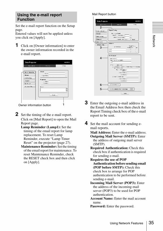
Set the e-mail report function on the Setup page.Entered values will not be applied unless you click on [Apply].
1 Click on [Owner information] to enter the owner information recorded in the e-mail report.
2 Set the timing of the e-mail report.Click on [Mail Report] to open the Mail Report page.Lamp Reminder (Lamp1): Set the
timing of the email report for lamp replacement. To reset Lamp Reminder, execute “Lamp Timer Reset” on the projector (page 27).
Maintenance Reminder: Set the timing of the email report for maintenance. To reset Maintenance Reminder, check the RESET check box and then click on [Apply].
3 Enter the outgoing e-mail address in the Email Address box then check the Report Timing check box of the e-mail report to be sent.
4 Set the mail account for sending e-mail reports.Mail Address: Enter the e-mail address.Outgoing Mail Server (SMTP): Enter
the address of outgoing mail server (SMTP).
Required Authentication: Check this check box if authentication is required for sending e-mail.
Requires the use of POP Authentication before sending email (POP before SMTP): Check this check box to arrange for POP authentication to be performed before sending e-mail.
Incoming Mail Server (POP3): Enter the address of the incoming-mail server (POP3) to be used for POP authentication.
Account Name: Enter the mail account name.
Password: Enter the password.
Using the e-mail report Function
1Owner information button
2
3
4
65
Mail Report button
35Using Network Features

36
SMTP Authentication: Check this check box to arrange for SMTP authentication to be performed before sending e-mail.
Account Name: Enter the mail account name.
Password: Enter the password.
5 Confirm the contents of the e-mail report.When you click on [View], the contents of the e-mail report are displayed.
6 Send the test mail.Check on the Send test mail check box then click on [Apply] to send your test mail to the e-mail address you set.
• The email report function will not work if the network uses Outbound Port25 blocking, which prevents access to the SMTP server.
• You cannot use the following characters to enter the characters in the text box: “ ' ”, “ “ ”, “ \ ”, “ & ”, “ < ”, “ > ”
Notes
Using Network Features
Interactive Function
B Interactive Function
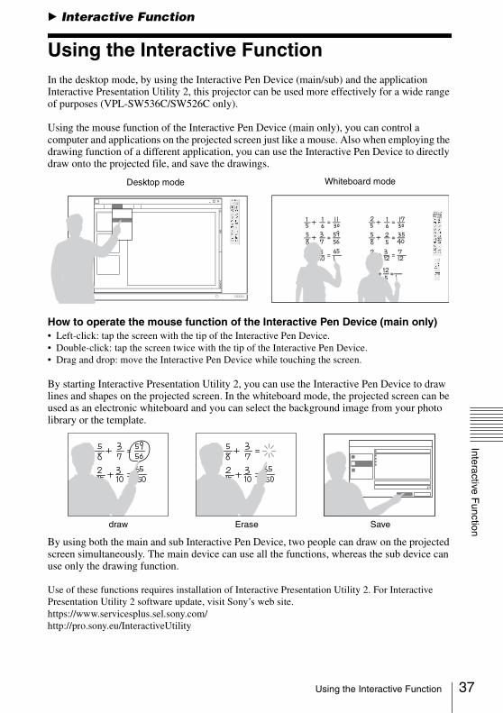
Using the Interactive FunctionIn the desktop mode, by using the Interactive Pen Device (main/sub) and the application Interactive Presentation Utility 2, this projector can be used more effectively for a wide range of purposes (VPL-SW536C/SW526C only).
Using the mouse function of the Interactive Pen Device (main only), you can control a computer and applications on the projected screen just like a mouse. Also when employing the drawing function of a different application, you can use the Interactive Pen Device to directly draw onto the projected file, and save the drawings.
How to operate the mouse function of the Interactive Pen Device (main only)• Left-click: tap the screen with the tip of the Interactive Pen Device.• Double-click: tap the screen twice with the tip of the Interactive Pen Device.• Drag and drop: move the Interactive Pen Device while touching the screen.
By starting Interactive Presentation Utility 2, you can use the Interactive Pen Device to draw lines and shapes on the projected screen. In the whiteboard mode, the projected screen can be used as an electronic whiteboard and you can select the background image from your photo library or the template.
By using both the main and sub Interactive Pen Device, two people can draw on the projected screen simultaneously. The main device can use all the functions, whereas the sub device can use only the drawing function.
Use of these functions requires installation of Interactive Presentation Utility 2. For Interactive Presentation Utility 2 software update, visit Sony’s web site. https://www.servicesplus.sel.sony.com/http://pro.sony.eu/InteractiveUtility
Desktop mode Whiteboard mode
draw Erase Save
37Using the Interactive Function
38
The interactive function works by a detector in the projector, which picks up infrared rays emitted from the tip of the Interactive Pen Device. Observe the precautions noted below.• Avoid placing the projector where the Interactive Pen detector is directly exposed to fluorescent
light or other strong light.• Do not cover the pen tip of the Interactive Pen Device or the Interactive Pen detector.• Infrared data communication or noise from another device may cause improper operation.Observe the precautions noted below during the calibration.• Avoid placing obstacles between the interactive detector and the screen.• Do not move the projector and the screen.If Calibration Auto does not calibrate properly, try the following methods.• Shield the screen from strong, direct outside light.• Reduce the ambient light while Calibration Auto is performed.• If Calibration Auto still does not calibrate properly after reducing the lighting as suggested above,
click “Calibration Main” and “Calibration Sub”, then calibrate manually.• If you use a screen which is not white, Calibration Auto may be inaccurate.
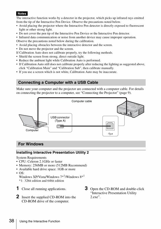
Make sure your computer and the projector are connected with a computer cable. For details on connecting the projector to a computer, see “Connecting the Projector” (page 9).
Installing Interactive Presentation Utility 2System Requirements• CPU: Celeron 2.1GHz or faster• Memory: 256MB or more (512MB Recommend)• Available hard drive space: 1GB or more• OS:
Windows XP/Vista/Windows 7*1/Windows 8*1
*1: 32bit edition and 64bit edition
1 Close all running applications.
2 Insert the supplied CD-ROM into the CD-ROM drive of the computer.
3 Open the CD-ROM and double-click “Interactive Presentation Utility 2.exe”.
Notes
Connecting a Computer with a USB Cable
For Windows
Computer cable
USB connector (Type A)
Computer
Using the Interactive Function

Interactive Function
4 Follow the on-screen instructions to install the software.To uninstall Interactive Presentation Utility 2, click [Start]-[All Programs]-[Interactive Presentation Utility 2]-[Uninstall].
Starting Interactive Presentation Utility 2To start Interactive Presentation Utility 2, click [Start]-[All Programs]-[Interactive Presentation Utility 2]-[Interactive Presentation Utility 2].
After the application starts, the icon appearsin the taskbar, and the toolbar appears on the screen.
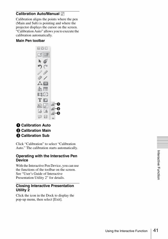
Calibration Auto/Manual Calibration aligns the points where the pen (Main and Sub) is pointing and where the projector displays the cursor on the screen. “Calibration Auto” allows you to execute the calibration automatically.
Click “Calibration” to select “Calibration Auto.” The calibration starts automatically.
Operating with the Interactive Pen DeviceWith the Interactive Pen Device, you can use the functions of the toolbar on the screen. See “User’s Guide of Interactive Presentation Utility 2” for details.
Closing Interactive Presentation Utility 2Click the icon in the Dock to display the pop-up menu, then select [Exit].
Taskbar
Toolbar
Projector connected to computer.
Projector not connected to computer.
a
b
c
Main Pen toolbar
a Calibration Autob Calibration Mainc Calibration Sub
39Using the Interactive Function

40
Installing Interactive Presentation Utility 2System Requirements• CPU: Pertium III or faster• Memory: 256MB or more (512MB Recommend)• Available hard drive space: 250MB• OS: Mac OS X 10.6 or later
Use of the interactive function requires installation of Interactive Presentation Utility 2.
1 Close all running applications.
2 In the CD-ROM, double-click [Interactive Presentation Utility 2.pkg].
3 Follow the on-screen instructions to install the software.To uninstall Interactive Presentation Utility 2, from the Application folder move the [Interactive Presentation Utility 2] folder into the Trash, then empty it.
Starting Interactive Presentation Utility 2Open the folder [Application] - [Interactive Presentation Utility 2] and double-click [Interactive Presentation Utility 2.app].After application starts, each icon appears in the Dock and the toolbar appears on the screen.
Icon for Interactive Presentation Utility 2
For Mac
Dock
Toolbar
Using the Interactive Function
Interactive Function
Calibration Auto/Manual Calibration aligns the points where the pen (Main and Sub) is pointing and where the projector displays the cursor on the screen. “Calibration Auto” allows you to execute the calibration automatically.
Click “Calibration” to select “Calibration Auto.” The calibration starts automatically.
Operating with the Interactive Pen DeviceWith the Interactive Pen Device, you can use the functions of the toolbar on the screen. See “User’s Guide of Interactive Presentation Utility 2” for details.
Closing Interactive Presentation Utility 2Click the icon in the Dock to display the pop-up menu, then select [Exit].
a
b
c
Main Pen toolbar
a Calibration Autob Calibration Mainc Calibration Sub
41Using the Interactive Function
42
B Presentation Function via Network
Using Presentation Function via NetworkThe Presentation Function via Network enables you to do the following:• Connect a maximum of 8 computers to the projector.• Project images from a maximum of 4 computers simultaneously.• Connecting a USB wireless LAN module (not supplied) to the projector allows the projector
to connect to up to 7 computers simultaneously.
Presentation Function via Network requires installation of Projector Station for Network Presentation (supplied CD-ROM). For information on updates of Projector Station for Network Presentation, visit Sony’s web site: https://www.servicesplus.sel.sony.com/System requirements for using the application are as follows.
OSWindowsXP: Home/Professional (recommended)WindowsVista: Home Premium/Business/Ultimate/EnterpriseWindows7: Home Premium/Professional (Recommended)/Ultimate/Enterprise
CPU Pentium4 2.8GHz or faster
• To install the application, administrative rights are required. • If you do not have administrative rights, the application may not run properly.• If firewall or security software is installed, the application may not run properly.• Depending on the type of network adapter, the application may not run properly.• Movie player (Media Player, etc.) images may not be projected properly.
1 Close all running applications.
2 Insert the supplied CD-ROM into the CD-ROM drive of the computer.
3 Open the CD-ROM and double-click the .exe file.When the message “User Account Control” is displayed, click “Allow” or “Yes.”
4 Follow the on-screen instructions to install the software.
1 Connect the projector to a network.For a wired connection, connect the projector by a LAN cable, then make the network settings (page 33).For a wireless connection, see “LAN connector” (page 10) or “USB connector (Type A) ( )” (page 10).
2 Turn on the projector.Select “Network” as the input source (page 14).
3 Start Projector Station for Network Presentation.Select [Start]-[All Programs]-[Projector Station for Network Presentation] on the computer.
Notes
Installing Projector Station for Network Presentation
Starting Projector Station for Network Presentation
Using Presentation Function via Network
Presentation F
unction via Netw
ork
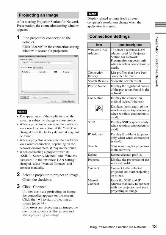
After starting Projector Station for Network Presentation, the connection setting window appears.
1 Find projectors connected to the network.Click “Search” in the connection setting window to search for projectors.
• The appearance of the application on the screen is subject to change without notice.
• When a projector is connected to a network via a wireless connection, if the “SSID” is changed from the factory default, it may not be found.
• When a projector is connected to a network via a wired connection, depending on the network environment, it may not be found.
• When connecting a projector with its “SSID”, “Security Method” and “Wireless Password” in the “Wireless LAN Setting” changed, select “Manual Connect” and connect manually.
2 Select a projector to project an image.Check the checkbox.
3 Click “Connect”.If other users are projecting an image, the controller appears on the screen. Click the to start projecting an image (page 44).If no users are projecting an image, the controller appears on the screen and starts projecting an image.
Display related settings (such as your computer’s resolution) change when the application is started.
Projecting an Image
Notes
Note
Connection Settings
Item Item descriptionsWireless LAN Adapter
To select a wireless LAN adapter used for Projector Station for Network Presentation (appears only when wireless connection is used).
Connection History
List profiles that have been connected before.
Search Results Show the search result.
Profile Name Display the registered names of the projectors found in the network.
Connection Display the connection method (wired/wireless).
Displays the strength of the wireless signal (appears only when wireless connection is used).
SSID Display SSID (appears only when wireless connection is used).
IP Address Display IP address (appears only when wired connection is used).
Search Start searching for projectors in the network.
Delete Delete selected profile.
Property Display the properties of the selected profile.
Connect Connect to the selected projector and start projecting an image.
Manual Connect
Enter the SSID and IP address manually to connect with the projector, and start projecting an image.
43Using Presentation Function via Network

44
You can project JPEG images, PDF files, etc. stored in a tablet PC/smartphone wirelessly by using a specific application.*1
For downloading*2 or detailed method of using the application, access the following URL.http://PWPresenter.pixelworks.com
*1: To use the application, one of the following conditions is required.• Connected to network where wireless
connection can be established (page 10).• Connected to a wireless network via USB
wireless LAN module IFU-WLM3 (not supplied) that is connected to the projector (page 10).
*2: Depending on your Internet connection, a data communication fee may apply.
Using the Controller
Items FunctionsStart projecting an image.
Pause projecting an image.
Stop projecting an image (screen turns black).
Change the application settings.
Disconnect from the projector.
Select a projection method then start projecting an image.
Projection method
Not projecting an image.
Project in full screen.
Project in the left half of the screen.
Project in the right half of the screen.
Project in the upper left quadrant of the screen.
Project in the upper right quadrant of the screen.
Project in the lower left quadrant of the screen.
Project in the lower right quadrant of the screen.
Display the strength of the wireless signal.
Display the number of users connected to the projector.
Display the users’ status.
NetworkPresentation
User 000001
8
Displaying Images or Files Sent from a Tablet PC/Smartphone
Using Presentation Function via Network

Projecting an Im
age using US
B C
onnection
B Projecting an Image using USB ConnectionProjecting an Image using USB ConnectionYou can also project an image simply by connecting the projector and computer with a USB A-B cable (not supplied).Projecting an image using USB connection requires to start USB Display. System requirements for using the application are as follows.
OSWindowsXP: Home/Professional (recommended)WindowsVista: Home Premium/Business/Ultimate/EnterpriseWindows7: Home Premium/Professional (Recommended)/Ultimate/Enterprise
CPU Pentium4 2.8GHz or faster
1 Connecting the projector and your computer with a USB A-B cable (not supplied) (page 10).
2 Turn on the projector.Select “Type B USB” as the input source (page 14). After a short time, the projector is recognized as a CD-ROM drive in the computer.
3 Open “USB Display” in the CD-ROM drive.
• The resolution of your computer changes when the application is started.• Depending of the computer’s setting, the application may start automatically.• When you are finished using the projector, you can simply disconnect the USB cable without using
the Safely Remove Hardware option.• Movie player (Media Player, etc.) images may not be projected properly.
After starting USB Display, the controller appears on the screen, and projection starts automatically.
Starting USB Display
Notes
Projecting an Image Using the Controller
Items FunctionsStart projecting an image.
Pause projecting an image.
Stop projecting an image (the screen turns black).
Display information about USB Display.
USB Display
45Projecting an Image using USB Connection

46
B USB Media Viewer
Using USB Media ViewerYou can browse image files stored in a USB memory device inserted in the USB connector of the projector, without using a computer.Supported storage media and file format:• Supported storage media: USB flash memory• Supported format of storage media: FAT format• Supported file format: JPEG (.jpg/.jpeg), Bitmap (.bmp), PNG (.png), GIF (.gif), TIFF (.tif/.tiff)
• exFAT, NTFS are not supported. • TIFF files containing EXIF information are not supported. • Image files in a USB memory device connected to the projector via a USB hub may not be
displayed.• Security protected USB memory may not function correctly. • A USB memory card reader that is recognized as more than one drive may not function correctly. • Display of image files that are larger than 4092 × 3072 pixels is not guaranteed. It may take a long
time to display, or may not be displayed.• A folder with a deep folder structure or with a very long folder name may not be displayed.• An image may not be displayed, depending on its file type.• Files or folders with names including non-alphanumeric characters may not be displayed.• When displaying an image file, do not disconnect the USB memory device. It may cause a
malfunction of the USB memory device or the projector. Disconnect the USB memory device when the USB Memory device selection screen is displayed.
1 Connect a USB Memory device to the projector (page 13).
2 Select “Type A USB” as the input source (page 14).
3 Select the USB Memory device.
Press the ENTER key to display in the thumbnail mode.USB Media Viewer has three display modes: “thumbnail mode,” “display mode” and “slideshow mode.”
Notes
Using USB Media Viewer
US
B M
edia View
er
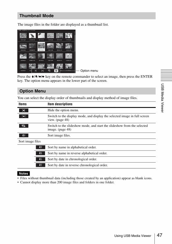
Press the V/v/B/b key on the remote commander to select an image, then press the ENTER key. The option menu appears in the lower part of the screen.
You can select the display order of thumbnails and display method of image files.
• Files without thumbnail data (including those created by an application) appear as blank icons.• Cannot display more than 200 image files and folders in one folder.
Thumbnail Mode
The image files in the folder are displayed as a thumbnail list.
Option menu
Option Menu
Items Item descriptions
Hide the option menu.
Switch to the display mode, and display the selected image in full screen view. (page 48)
Switch to the slideshow mode, and start the slideshow from the selected image. (page 48)
Sort image files.
Sort image files
Sort by name in alphabetical order.
Sort by name in reverse alphabetical order.
Sort by date in chronological order.
Sort by date in reverse chronological order.
Notes
az
az
az
12
21
47Using USB Media Viewer
48
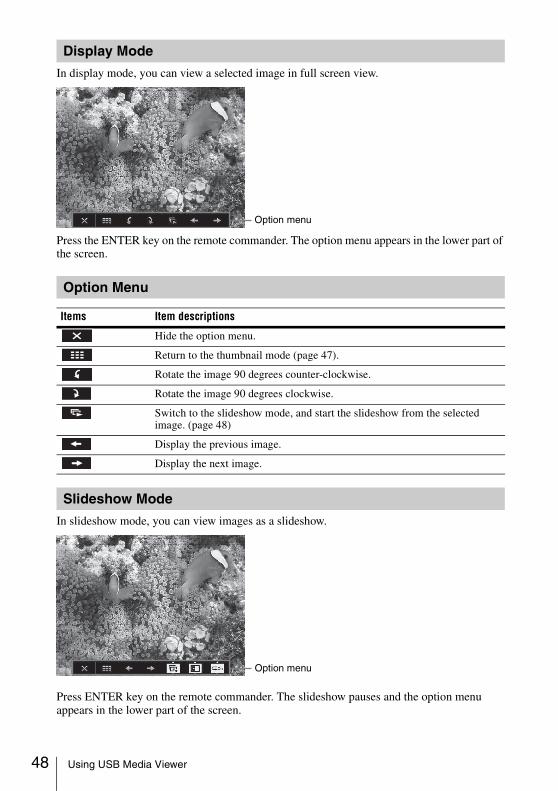
In display mode, you can view a selected image in full screen view.
Press the ENTER key on the remote commander. The option menu appears in the lower part of the screen.
In slideshow mode, you can view images as a slideshow.
Press ENTER key on the remote commander. The slideshow pauses and the option menu appears in the lower part of the screen.
Display Mode
Option menu
Option Menu
Items Item descriptions
Hide the option menu.
Return to the thumbnail mode (page 47).
Rotate the image 90 degrees counter-clockwise.
Rotate the image 90 degrees clockwise.
Switch to the slideshow mode, and start the slideshow from the selected image. (page 48)
Display the previous image.
Display the next image.
Slideshow Mode
Option menu
Using USB Media Viewer
US
B M
edia View
er
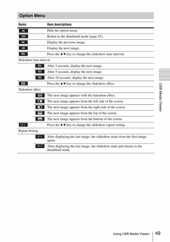
Option Menu
Items Item descriptions
Hide the option menu.
Return to the thumbnail mode (page 47).
Display the previous image.
Display the next image.
Press the V/v key to change the slideshow time interval.
Slideshow time interval
After 3 seconds, display the next image.
After 5 seconds, display the next image.
After 10 seconds, display the next image.
Press the V/v key to change the slideshow effect.
Slideshow effect
The next image appears with tile transition effect.
The next image appears from the left side of the screen.
The next image appears from the right side of the screen.
The next image appears from the top of the screen.
The next image appears from the bottom of the screen.
Press the V/v key to change the slideshow repeat setting.
Repeat Setting
After displaying the last image, the slideshow starts from the first image again.
After displaying the last image, the slideshow ends and returns to the thumbnail mode.
3
3
5
10
On
On
Off
49Using USB Media Viewer
50
B Others
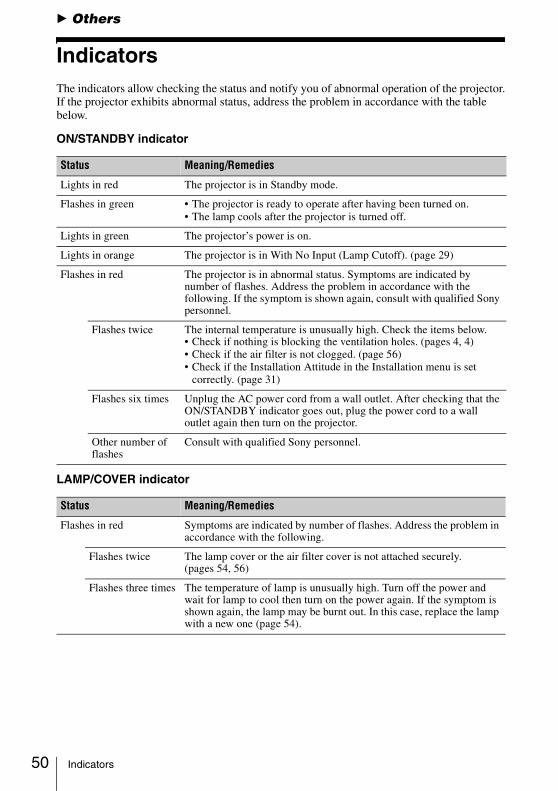
IndicatorsThe indicators allow checking the status and notify you of abnormal operation of the projector.If the projector exhibits abnormal status, address the problem in accordance with the table below.
ON/STANDBY indicator
LAMP/COVER indicator
Status Meaning/Remedies
Lights in red The projector is in Standby mode.
Flashes in green • The projector is ready to operate after having been turned on. • The lamp cools after the projector is turned off.
Lights in green The projector’s power is on.
Lights in orange The projector is in With No Input (Lamp Cutoff). (page 29)
Flashes in red The projector is in abnormal status. Symptoms are indicated by number of flashes. Address the problem in accordance with the following. If the symptom is shown again, consult with qualified Sony personnel.
Flashes twice The internal temperature is unusually high. Check the items below.• Check if nothing is blocking the ventilation holes. (pages 4, 4)• Check if the air filter is not clogged. (page 56)• Check if the Installation Attitude in the Installation menu is set
correctly. (page 31)
Flashes six times Unplug the AC power cord from a wall outlet. After checking that the ON/STANDBY indicator goes out, plug the power cord to a wall outlet again then turn on the projector.
Other number of flashes
Consult with qualified Sony personnel.
Status Meaning/Remedies
Flashes in red Symptoms are indicated by number of flashes. Address the problem in accordance with the following.
Flashes twice The lamp cover or the air filter cover is not attached securely. (pages 54, 56)
Flashes three times The temperature of lamp is unusually high. Turn off the power and wait for lamp to cool then turn on the power again. If the symptom is shown again, the lamp may be burnt out. In this case, replace the lamp with a new one (page 54).
Indicators
Others
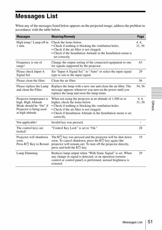
Messages ListWhen any of the messages listed below appears on the projected image, address the problem in accordance with the table below.
Messages Meaning/Remedy Page
High temp.! Lamp off in 1 min.
Check the items below.• Check if nothing is blocking the ventilation holes.• Check if the air filter is not clogged.• Check if the Installation Attitude in the Installation menu is
set correctly.
4, 4, 31, 56
Frequency is out of range!
Change the output setting of the connected equipment to one for signals supported by the projector.
63
Please check Input-A Signal Sel.
Set “Input-A Signal Sel.” to “Auto” or select the input signal type to suit to the input signal.
29
Please clean the filter. Clean the air filter. 56
Please replace the Lamp and clean the Filter.
Replace the lamp with a new one and clean the air filter. The message appears whenever you turn on the power until you replace the lamp and reset the lamp timer.
54, 56
Projector temperature is high. High Altitude Mode should be “On” if Projector is being used at high altitude.
When not using the projector at an altitude of 1,500 m or higher, check the items below.• Check if nothing is blocking the ventilation holes.• Check if the air filter is not clogged.• Check if Installation Attitude in the Installation menu is set
correctly.
4, 4, 31, 56
Not applicable! Invalid key was pressed. –
The control keys are locked!
“Control Key Lock” is set to “On.” 28
Projector will shutdown soon.Press ?/1 Key to Restart
The ?/1 key was pressed and the projector will be shut down soon. To cancel shutdown, press the ?/1 key again (the projector will remain on). To turn off the projector directly, press and hold the ?/1 key.
19
Lamp Dimming Reduces lamp output when “With Static Signal” is set. When any change in signal is detected, or an operation (remote control or control panel) is performed, normal brightness is restored.
29
51Messages List
52
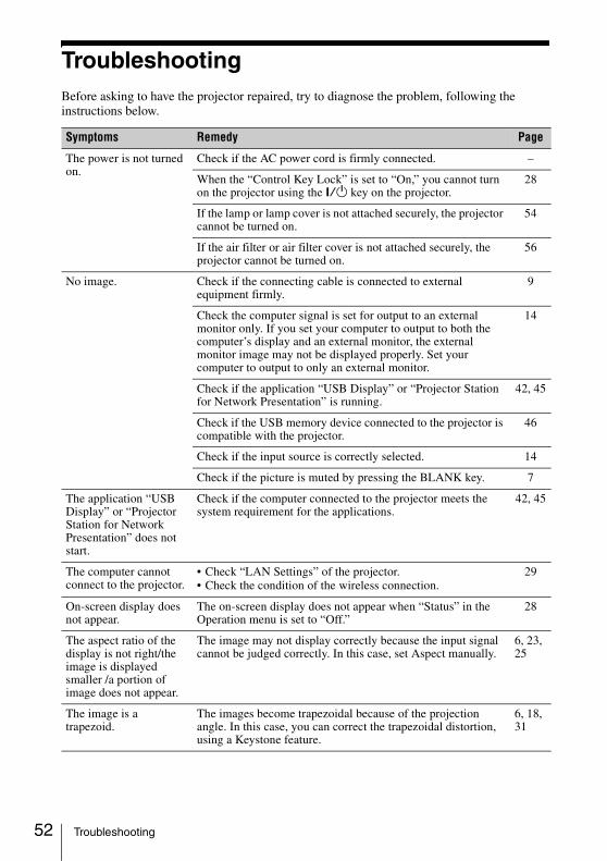
TroubleshootingBefore asking to have the projector repaired, try to diagnose the problem, following the instructions below.
Symptoms Remedy Page
The power is not turned on.
Check if the AC power cord is firmly connected. –
When the “Control Key Lock” is set to “On,” you cannot turn on the projector using the ?/1 key on the projector.
28
If the lamp or lamp cover is not attached securely, the projector cannot be turned on.
54
If the air filter or air filter cover is not attached securely, the projector cannot be turned on.
56
No image. Check if the connecting cable is connected to external equipment firmly.
9
Check the computer signal is set for output to an external monitor only. If you set your computer to output to both the computer’s display and an external monitor, the external monitor image may not be displayed properly. Set your computer to output to only an external monitor.
14
Check if the application “USB Display” or “Projector Station for Network Presentation” is running.
42, 45
Check if the USB memory device connected to the projector is compatible with the projector.
46
Check if the input source is correctly selected. 14
Check if the picture is muted by pressing the BLANK key. 7
The application “USB Display” or “Projector Station for Network Presentation” does not start.
Check if the computer connected to the projector meets the system requirement for the applications.
42, 45
The computer cannot connect to the projector.
• Check “LAN Settings” of the projector.• Check the condition of the wireless connection.
29
On-screen display does not appear.
The on-screen display does not appear when “Status” in the Operation menu is set to “Off.”
28
The aspect ratio of the display is not right/the image is displayed smaller /a portion of image does not appear.
The image may not display correctly because the input signal cannot be judged correctly. In this case, set Aspect manually.
6, 23, 25
The image is a trapezoid.
The images become trapezoidal because of the projection angle. In this case, you can correct the trapezoidal distortion, using a Keystone feature.
6, 18, 31
Troubleshooting
Others
The image is dark/too bright.
The settings for “Brightness,” “Contrast,” and “Lamp Mode” affect brightness of the image. Check if the value is appropriate.
22, 29
The image will be dark when the lamp is burnt out. Check “Lamp Timer,” and replace the lamp with a new one if necessary.
32, 54
“With Static Signal” is set to “On.” 29
During picture muting, the lamp is dimmed to reduce power consumption.
29
When video signal is not input, the lamp is dimmed to reduce power consumption.
–
The image becomes darker or brighter.
When the lamp is dimmed for a long time, brightness may increase temporarily, but this is not malfunction.
–
When the “Lamp Mode” is set to “Auto,” the luminance of the lamp changes according to the input image.
29
The image is not clear. Check if the projector is in focus. 16
The picture will not be clear if condensation has accumulated on the lens. In this case, let the projector sit for about two hours with the power on.
–
The image is noisy. Check if the connecting cable is connected to the external equipment properly.
9
No sound. Check that the connecting cables between the projector and external video or audio equipment are securely connected.
9
Check if the external audio equipment is set properly. –
Check if the “Speaker” is not set to “Off”. 27
Audio is not output if audio muting is activated. 7
Check if the volume is not set to minimum. 7, 27
The remote commander does not work.
Check if the batteries are installed correctly. –
Check if the batteries are not exhausted. –
The fan is noisy. The sound from the fan is often greater than normal to cool the lamp, etc. in the following cases.• “Lamp Mode” is set to “High.”• The unit is used at a high altitude. “High Altitude Mode” is
set to “On.”• The unit is used in the location where the temperature is high.
29, 31
If the ventilation holes are blocked, the internal temperature of the projector rises and the fan noise becomes larger.
4, 4
Symptoms Remedy Page
53Troubleshooting
54
Replacing the LampReplace the lamp with a new one if a message displayed on the projected image or the LAMP/COVER indicator notifies you to replace the lamp (pages 50, 51).Use an LMP-E212 projector lamp (not supplied) for replacement.
• The lamp remains hot after the projector is turned off. If you touch the lamp, you may burn your finger. When you replace the lamp, wait for at least an hour after turning off the projector for the lamp to cool sufficiently.
• Do not allow any metallic or inflammable objects into the lamp replacement slot after removing the lamp, otherwise it may cause electrical shock or fire. Do not put your hands into the slot.
• If the lamp breaks, contact qualified Sony personnel. Do not replace the lamp yourself.
• When removing the lamp, be sure to pull it out straight, by holding the designated location. If you touch a part of the lamp other than the designated location, you may be burned or injured. If you pull out the lamp while the projector is tilted, the pieces may scatter if the lamp breaks any may cause injury.
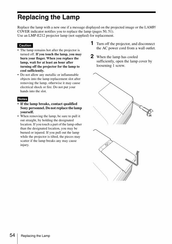
1 Turn off the projector, and disconnect the AC power cord from a wall outlet.
2 When the lamp has cooled sufficiently, open the lamp cover by loosening 1 screw.
Caution
Notes
Replacing the Lamp
Others
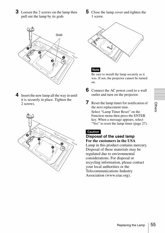
3 Loosen the 2 screws on the lamp then pull out the lamp by its grab.
4 Insert the new lamp all the way in until it is securely in place. Tighten the 2 screws.
5 Close the lamp cover and tighten the 1 screw.
Be sure to install the lamp securely as it was. If not, the projector cannot be turned on.
6 Connect the AC power cord to a wall outlet and turn on the projector.
7 Reset the lamp timer for notification of the next replacement time.Select “Lamp Timer Reset” on the Function menu then press the ENTER key. When a message appears, select “Yes” to reset the lamp timer (page 27).
Disposal of the used lampFor the customers in the USALamp in this product contains mercury. Disposal of these materials may be regulated due to environmental considerations. For disposal or recycling information, please contact your local authorities or the Telecommunications Industry Association (www.eiae.org).
Grab
Note
Caution
55Replacing the Lamp
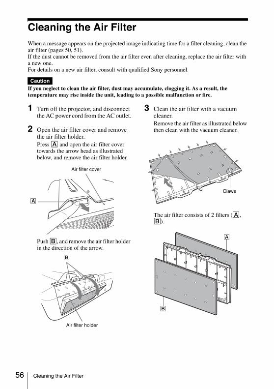
56
Cleaning the Air FilterWhen a message appears on the projected image indicating time for a filter cleaning, clean the air filter (pages 50, 51).If the dust cannot be removed from the air filter even after cleaning, replace the air filter with a new one.For details on a new air filter, consult with qualified Sony personnel.
If you neglect to clean the air filter, dust may accumulate, clogging it. As a result, the temperature may rise inside the unit, leading to a possible malfunction or fire.
1 Turn off the projector, and disconnect the AC power cord from the AC outlet.
2 Open the air filter cover and remove the air filter holder.Press A and open the air filter cover towards the arrow head as illustrated below, and remove the air filter holder.
Push B, and remove the air filter holder in the direction of the arrow.
3 Clean the air filter with a vacuum cleaner.Remove the air filter as illustrated below then clean with the vacuum cleaner.
The air filter consists of 2 filters (A, B).
Caution
Air filter cover
A
Air filter holder
B
Claws
A
B
Cleaning the Air Filter

Others
4 Reattach the air filter cover to the unit.
Be sure to attach the air filter cover firmly. If not, the projector cannot be turned on.
Note
A
B
57Cleaning the Air Filter

58
Specifications
Items Descriptions
Model VPL-SW536C/SW526C/SW536/SW526/VPL-SX536
Projection system 3 LCD system
Display device Effective display size
VPL-SW536C/SW526C/SW536/SW526: 0.75 inch (19.0 mm), 3 plate panels, Aspect ratio 16:10VPL-SX536: 0.63 inch (16.0 mm), 3 plate panels, Aspect ratio 4:3
Effective picture elements
VPL-SW536C/SW526C/SW536/SW526: 3,072,000 pixels (1280 × 800 pixels, 3 plate panels)VPL-SX536: 2,359,296 pixels (1024 × 768 pixels, 3 plate panels)
Projection lens Zoom Manual zoom approx.1.05 times
Focus Manual
Light source High-pressure mercury lamp, 210 W type
Projected image size
VPL-SW536C/SW526C/SW536/SW526: 70 inches to 130 inches (1.78 m to 3.30 m)VPL-SX536: 60 inches to 110 inches (1.52 m to 2.79 m)
Luminous flux (Brightness)
VPL-SW536C/SW536: 3100 lmVPL-SX536: 3000 lmVPL-SW526C/SW526: 2500 lm(when “Lamp Mode” is set to “High”)
Speaker 16 W × 1 (monaural)
Applicable scanning frequency*1
Horizontal: 15 kHz to 92 kHz, Vertical: 48 Hz to 92 Hz
Resolution*1 When a computer signal is input
Maximum display resolution: 1600 × 1200 pixels (resize)Panel display resolution: VPL-SW536C/SW526C/SW536/SW526: 1280 × 800 pixelsVPL-SX536: 1024 × 768 pixels
When a video signal is input
NTSC, PAL, SECAM, 480/60i, 576/50i, 480/60p, 576/50p, 720/60p, 720/50p, 1080/60i, 1080/50i, 1080/60p, 1080/50p
Color system NTSC3.58, PAL, SECAM, NTSC4.43, PAL-M, PAL-N
Specifications

Others
INPUT OUTPUT (Computer/video)
INPUT A RGB/YPBPR input connector: Mini D-sub 15 pin female, G with sync/Y: 1 Vp-p ± 2 dB, sync negative, 75 ohms terminated, RGB/PBPR: 0.7 Vp-p ± 2 dB, 75 ohms terminated, Sync signal: TTL level high impedance, positive/negativeAudio input connector: Stereo mini jack, rated input 500 mVrms, input impedance more than 47 kohms
INPUT B RGB input connector: Mini D-sub 15-pin female, RGB: 0.7 Vp-p ± 2 dB, 75 ohms terminated, Sync signal: TTL level high impedance, positive/negativeAudio input connector: Stereo mini jack, rated input 500 mVrms, input impedance more than 47 kohms
INPUT C HDMI input connector: HDMI 19-pin, HDCP, HDMI audio support
S VIDEO (S VIDEO IN)
S video input connector: Mini DIN 4-pin, Y: 1 Vp-p ± 2 dB, sync negative, 75 ohmes terminated, C: (burst signal) 0.286 (NTSC)/0.3 (PAL/SECAM) Vp-p ± 2 dB, 75 ohms terminated Audio input connector: Phono jack × 2, rated input 500 mVrms, Input impedance more than 47 kohms
VIDEO (VIDEO IN)
Video input connector: Pin jack, 1 Vp-p ± 2 dB, sync negative, 75 ohmes terminatedAudio input connector: Shared with S VIDEO IN
OUTPUT MONITOR output connector: Mini D-sub 15-pin female, G with sync/Y: 1 Vp-p ± 2 dB, sync negative, 75 ohms terminated, RGB/PBPR: 0.7 Vp-p ± 2 dB, 75 ohms terminated, Sync signal: HD, VD 4 V (open), 1 Vp-p (75 ohms), positive/negativeAudio output connector: Stereo mini jack, stereo, 1 Vrms (maximum volume, when inputting 500 mVrms), output impedance 5 kohms
Other conncectors RS-232C connector: D-Sub 9 pin male
LAN connector: RJ45, 10BASE-T/100BASE-TX
USB connector: Type A
USB connector: Type B
Microphone input: Mini jack
Operating temperature/Operating humidity
0 °C to 40 °C (32 °F to 104 °F)/35% ~ 85% (no condensation)
Storage temperature/Storage humidity
–20 °C to +60 °C (–4 °F to +140 °F)/10% to 90% (no condensation)
Power requirements
VPL-SW536C/SW526C/SW536/SW526:100 V to 240 V AC, 3.0-1.3 A, 50/60 HzVPL-SX536:100 V to 240 V AC, 3.1-1.4 A, 50/60 Hz
Items Descriptions
Model VPL-SW536C/SW526C/SW536/SW526/VPL-SX536
59Specifications
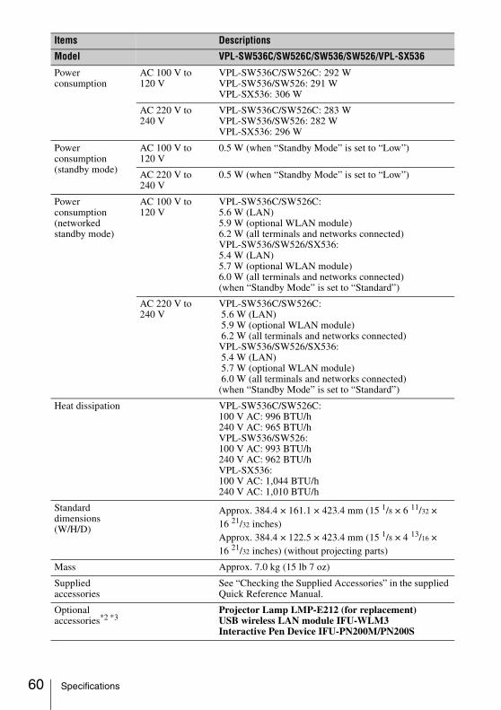
60
Power consumption
AC 100 V to 120 V
VPL-SW536C/SW526C: 292 WVPL-SW536/SW526: 291 WVPL-SX536: 306 W
AC 220 V to 240 V
VPL-SW536C/SW526C: 283 WVPL-SW536/SW526: 282 WVPL-SX536: 296 W
Power consumption(standby mode)
AC 100 V to 120 V
0.5 W (when “Standby Mode” is set to “Low”)
AC 220 V to 240 V
0.5 W (when “Standby Mode” is set to “Low”)
Power consumption(networked standby mode)
AC 100 V to 120 V
VPL-SW536C/SW526C:5.6 W (LAN) 5.9 W (optional WLAN module)6.2 W (all terminals and networks connected) VPL-SW536/SW526/SX536:5.4 W (LAN) 5.7 W (optional WLAN module)6.0 W (all terminals and networks connected) (when “Standby Mode” is set to “Standard”)
AC 220 V to 240 V
VPL-SW536C/SW526C: 5.6 W (LAN) 5.9 W (optional WLAN module) 6.2 W (all terminals and networks connected) VPL-SW536/SW526/SX536: 5.4 W (LAN) 5.7 W (optional WLAN module) 6.0 W (all terminals and networks connected)(when “Standby Mode” is set to “Standard”)
Heat dissipation VPL-SW536C/SW526C: 100 V AC: 996 BTU/h240 V AC: 965 BTU/hVPL-SW536/SW526:100 V AC: 993 BTU/h240 V AC: 962 BTU/hVPL-SX536:100 V AC: 1,044 BTU/h240 V AC: 1,010 BTU/h
Standard dimensions(W/H/D)
Approx. 384.4 × 161.1 × 423.4 mm (15 1/8 × 6 11/32 × 16 21/32 inches)Approx. 384.4 × 122.5 × 423.4 mm (15 1/8 × 4 13/16 × 16 21/32 inches) (without projecting parts)
Mass Approx. 7.0 kg (15 lb 7 oz)
Supplied accessories
See “Checking the Supplied Accessories” in the supplied Quick Reference Manual.
Optional accessories*2 *3
Projector Lamp LMP-E212 (for replacement)USB wireless LAN module IFU-WLM3Interactive Pen Device IFU-PN200M/PN200S
Items Descriptions
Model VPL-SW536C/SW526C/SW536/SW526/VPL-SX536
Specifications
Others
*1: For details, refer to “Acceptable Input Signals*1” on page 63.*2: Information on accessories in this manual is current as of October 2014.*3: Not all optional accessories are available in all countries and area. Please check with your local
Sony Authorized Dealer.
Design and specifications of the unit, including the optional accessories, are subject to change without notice.
Notes
61Specifications
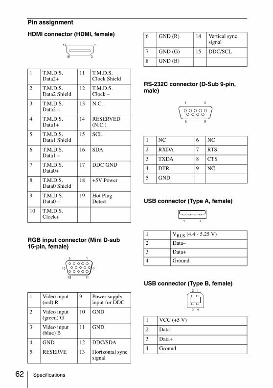
62
Pin assignment
HDMI connector (HDMI, female)
RGB input connector (Mini D-sub 15-pin, female)
RS-232C connector (D-Sub 9-pin, male)
USB connector (Type A, female)
USB connector (Type B, female)
1 T.M.D.S. Data2+
11 T.M.D.S. Clock Shield
2 T.M.D.S. Data2 Shield
12 T.M.D.S. Clock –
3 T.M.D.S. Data2 –
13 N.C.
4 T.M.D.S. Data1+
14 RESERVED (N.C.)
5 T.M.D.S. Data1 Shield
15 SCL
6 T.M.D.S. Data1 –
16 SDA
7 T.M.D.S. Data0+
17 DDC GND
8 T.M.D.S. Data0 Shield
18 +5V Power
9 T.M.D.S. Data0 –
19 Hot Plug Detect
10 T.M.D.S. Clock+
1 Video input (red) R
9 Power supply input for DDC
2 Video input (green) G
10 GND
3 Video input(blue) B
11 GND
4 GND 12 DDC/SDA
5 RESERVE 13 Horizontal sync signal
1
2
19
18
6 GND (R) 14 Vertical sync signal
7 GND (G) 15 DDC/SCL
8 GND (B)
1 NC 6 NC
2 RXDA 7 RTS
3 TXDA 8 CTS
4 DTR 9 NC
5 GND
1 VBUS (4.4 - 5.25 V)
2 Data–
3 Data+
4 Ground
1 VCC (+5 V)
2 Data-
3 Data+
4 Ground
51
96
Specifications
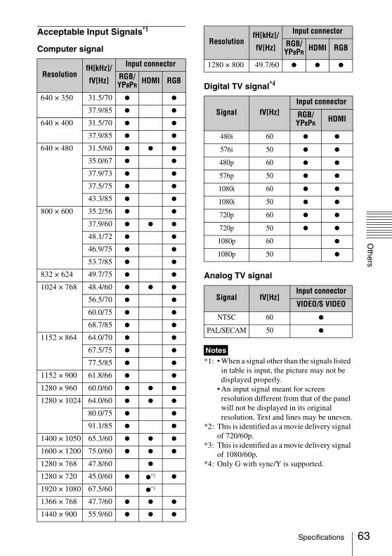
Others
Acceptable Input Signals*1
Computer signal
Digital TV signal*4
Analog TV signal
*1: • When a signal other than the signals listed in table is input, the picture may not be displayed properly.
• An input signal meant for screen resolution different from that of the panel will not be displayed in its original resolution. Text and lines may be uneven.
*2: This is identified as a movie delivery signal of 720/60p.
*3: This is identified as a movie delivery signal of 1080/60p.
*4: Only G with sync/Y is supported.
ResolutionfH[kHz]/
fV[Hz]
Input connector
RGB/YPBPR
HDMI RGB
640 × 350 31.5/70 z z
37.9/85 z z
640 × 400 31.5/70 z z
37.9/85 z z
640 × 480 31.5/60 z z z
35.0/67 z z
37.9/73 z z
37.5/75 z z
43.3/85 z z
800 × 600 35.2/56 z z
37.9/60 z z z
48.1/72 z z
46.9/75 z z
53.7/85 z z
832 × 624 49.7/75 z z
1024 × 768 48.4/60 z z z
56.5/70 z z
60.0/75 z z
68.7/85 z z
1152 × 864 64.0/70 z z
67.5/75 z z
77.5/85 z z
1152 × 900 61.8/66 z z
1280 × 960 60.0/60 z z z
1280 × 1024 64.0/60 z z z
80.0/75 z z
91.1/85 z z
1400 × 1050 65.3/60 z z z
1600 × 1200 75.0/60 z z z
1280 × 768 47.8/60 z
1280 × 720 45.0/60 z z*2 z
1920 × 1080 67.5/60 z*3
1366 × 768 47.7/60 z z z
1440 × 900 55.9/60 z z z
1280 × 800 49.7/60 z z z
Signal fV[Hz]Input connector
RGB/YPBPR
HDMI
480i 60 z z
576i 50 z z
480p 60 z z
576p 50 z z
1080i 60 z z
1080i 50 z z
720p 60 z z
720p 50 z z
1080p 60 z
1080p 50 z
Signal fV[Hz]Input connector
VIDEO/S VIDEO
NTSC 60 z
PAL/SECAM 50 z
Notes
ResolutionfH[kHz]/
fV[Hz]
Input connector
RGB/YPBPR
HDMI RGB
63Specifications

64
Projection Distance and Lens Shift RangeThe projection distance is the distance between the center of the projection window and the surface of the projected image. The following describes the projection distance and height from the center of the projection window to edge of screen by each projected screen size. Height H is the height from the bottom of the projected image (top for wall mount) to A (determined by drawing a perpendicular line from the center of the projection window to projected image surface).
Floor Installation
Projection distance L
Projected image
Center of the projection window
Height H from center of projection window to bottom of screen
A
Projection Distance and Lens Shift Range

Others
Wall Installation
L: Projection distance LH: Distance between the edge of the image and the center of the projection window
The lens shift range is the distance you can move the lens shift from the center of the projected image(0) when full width and full height of the projected image is regarded as 100%.
VSUP: Vertical lens shift range (up) [%]VSDN: Vertical lens shift range (down) [%]HSR: Horizontal lens shift range (right) [%]HSL: Horizontal lens shift range (left) [%]
Projection distance L
Height H from center of the projection window to top of screen
Center of the projection window
Projected image
A
VSUP
HSL HSR
VSDN Projected image
Center of the projected image
Shaded region: Lens shift range
65Projection Distance and Lens Shift Range
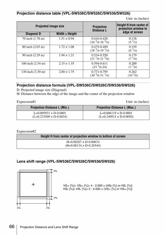
66
Projection distance table (VPL-SW536C/SW526C/SW536/SW526)Unit: m (inches)
Projection distance formula (VPL-SW536C/SW526C/SW536/SW526)D: Projected image size (Diagonal)H: Distance between the edge of the image and the center of the projection window
Expression#1 Unit: m (inches)
Expression#2
Lens shift range (VPL-SW536C/SW526C/SW536/SW526)
Projected image size Projection Distance L
Height H from center of projection window to
edge of screenDiagonal D Width × Height70 inch (1.78 m) 1.51 × 0.94 0.416-0.428
(16 3/8-16 3/4) 0.138 (5 1/2)
80 inch (2.03 m) 1.72 × 1.08 0.475-0.489 (18 3/4-19 1/4)
0.159 (6 1/4)
90 inch (2.29 m) 1.94 × 1.21 0.534-0.550 (21 1/8-21 5/8)
0.179 (7 1/8)
100 inch (2.54 m) 2.15 × 1.35 0.594-0.611 (23 3/8-24)
0.200 (7 7/8)
130 inch (3.30 m) 2.80 × 1.75 0.771-0.795 (30 3/8-31 1/4)
0.262 (10 3/8)
Projection Distance L (Min.) Projection Distance L (Max.)
L=0.005931 × D-0.0001(L=0.233509 × D-0.0024)
L=0.006119 × D-0.0001(L=0.240915 × D-0.0050)
Height H from center of projection window to bottom of screen
H=0.00207 × D-0.00674(H=0.08134 × D-0.26544)
VSUP [%]= VSDN [%]= 4 - 2.000 × (HSR [%] or HSL [%])HSR [%]= HSL [%]= 2 - 0.500 × (VSUP [%] or VSDN [%])
Projection Distance and Lens Shift Range
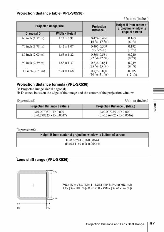
Others
Projection distance table (VPL-SX536)Unit: m (inches)
Projection distance formula (VPL-SX536)D: Projected image size (Diagonal)H: Distance between the edge of the image and the center of the projection window
Expression#1 Unit: m (inches)
Expression#2
Lens shift range (VPL-SX536)
Projected image size Projection Distance L
Height H from center of projection window to
edge of screenDiagonal D Width × Height60 inch (1.52 m) 1.22 × 0.91 0.424-0.436
(16 3/4-17 1/8)0.163 (6 1/2)
70 inch (1.78 m) 1.42 × 1.07 0.495-0.509 (19 1/2-20)
0.192 (7 5/8)
80 inch (2.03 m) 1.63 × 1.22 0.566-0.581 (22 3/8-22 7/8)
0.220 (8 3/4)
90 inch (2.29 m) 1.83 × 1.37 0.636-0.654 (25 1/8-25 3/4)
0.249 (9 7/8)
110 inch (2.79 m) 2.24 × 1.68 0.778-0.800 (30 5/8-31 3/8)
0.305 (12 1/8)
Projection Distance L (Min.) Projection Distance L (Max.)
L=0.007067 × D-0.0001(L=0.278225 × D-0.0047)
L=0.007275 × D-0.0001(L=0.286402 × D-0.0046)
Height H from center of projection window to bottom of screen
H=0.00284 × D-0.00674(H=0.11169 × D-0.26544)
VSUP [%]= VSDN [%]= 4 - 1.333 × (HSR [%] or HSL [%])HSR [%]= HSL [%]= 3 - 0.750 × (VSUP [%] or VSDN [%])
67Projection Distance and Lens Shift Range
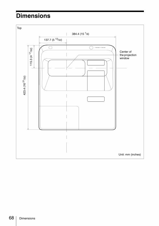
68
Dimensions
384.4 (15 1/8)
137.7 (5 13/32)
423.
4 (1
6 21
/32)
115.
3 (4
17/3
2)
Center of the projection window
Unit: mm (inches)
Top
Dimensions

Others
Side
Center of the projection window
150.
5 (5
15/1
6)
125.
5 (4
15/1
6)
122.
5 (4
13/1
6)
124
(4 7 /
8)
149
(5 7 /
8)
161.
1 (6
11/3
2)
Unit: mm (inches)
Bottom
Center of the projection window
150.3 (5 29/32)
71 (2 25/32)
16 (5/8)6.6 (1/4)
253.
4 (9
31/3
2)
211.
3 (8
5 /16
)
51.3
(2
1 /32
)
19.7 (25/32)
199 (7 27/32) 90 (3 17/32)
Unit: mm (inches)
180 (7 3/32)
Ø26
(1 1 /32)Ø26 (1 1/32)
69Dimensions
70
IndexAAC IN ........................................................ 5Acceptable input signal ........................... 63Adjust Signal ........................................... 24Adjuster ............................................... 4, 18Air filter ................................................... 56Air filter cover/Ventilation holes
(intake) ............................................... 4APA ........................................................... 6Aspect ........................................... 6, 23, 25
BBLANK ..................................................... 7Brightness ............................................... 22
CCC Display .............................................. 27Color ....................................................... 22Color Temp. ............................................ 22Connecting a computer ............................. 9Connecting a Video equipment ............... 11Connecting an external monitor and audio
equipment ........................................ 13Connector panel .................................... 4, 5Contrast ................................................... 22Control Key Lock .................................... 28Control Panel Keys ................................... 6Control Window ...................................... 33
DDigital Zoom ............................................. 6
EECO MODE (Energy-saving mode) ......... 7
FfH ............................................................ 32Focus ....................................................... 16Focus ring .................................................. 4Freeze ........................................................ 7fV ............................................................ 32
GGamma Mode .......................................... 22
HH (Horizontal) .........................................24High Altitude Mode .................................31Hue ..........................................................22
IImage Flip ................................................31Information menu ....................................32Input ...........................................................5Installation menu .....................................31Interactive Function .................................37Interactive Pen detector .............................4Interactive Pen Device ...............................8
KKeystone ..............................................6, 18
LLamp cover ................................................4Lamp Timer .............................................32Lamp Timer Reset ...................................27LAMP/COVER indicator ....................4, 50LAN connector ..........................................5Language .................................................28Link to Image Flip ...................................31Location and function of controls ..............4
MMain unit ...................................................4Messages list ............................................51Model Name ............................................32MUTING ...................................................7
NNetwork Features ...............................33, 42
OOperation menu .......................................28Optional accessories ................................60Output ........................................................5
PPhase, Pitch, Shift ....................................24Picture menu ............................................22Picture mode ............................................22Pin assignment .........................................62Projecting an image .................................14Projection distance ...................................64
Index
Others
Projector Station for Network Presentation .....................................42
RRemote commander ...................................6Remote control detector ............................4Replacing the lamp ..................................54RS-232C ....................................................5
SSecurity bar ...............................................4Security Lock ......................................4, 28Selecting an input signal ...........................6Serial No. .................................................32Sharpness .................................................22Signal Type ..............................................32Smart APA ...............................................27Specifications ..........................................58Start Up Image ........................................27Status .......................................................28
TThe Connection/Power Menu ..................29The Function menu ..................................27The Screen menu .....................................23Troubleshooting .......................................52Turn off ................................................6, 19Turn on ................................................6, 14
UUSB Display ............................................45USB Media Viewer .................................46Using a menu ...........................................21Using the e-mail report Function ............35
VVentilation holes ........................................4Volume ......................................................7
WWith No Input ..........................................29With Static Signal ....................................29
About Trademarks• Adobe and Adobe Acrobat are trademarks
or registered trademarks of Adobe Systems Incorporated in the United States and/or other countries.
• Kensington is a registered trademark of Kensington Technology Group.
• The terms HDMI and HDMI High-Definition Multimedia Interface, and the HDMI Logo are trademarks or registered trademarks of HDMI Licensing LLC in the United States and other countries.
• Internet Explore is registered trademarks of Microsoft Corporation in the United States and/or other countries.
• PJLink is a registered trademark of Japan Business Machine and Information System Industries Association.
• AMX is a trademark of AMX Corporation.• Crestron RoomView is a trademark of
Crestron Corporation.• Mac and Mac OS are registered
trademarks of Apple Inc. in the U.S. and other countries.
• All other trademarks and registered trademarks are trademarks or registered trademarks of their respective holders. In this manual, ™ and ® marks are not specified.
71Index

Sony Corporation