data sheet em-mpo/.., enc2/s - energy controls...
TRANSCRIPT

1EM-MPO/.., ENC2/S Data Sheet TA200268 Issue 2/C 20/02/07
Data Sheet
EM-MPO/.., ENC2/SMulti-Parameter Electricity Meters and Node Controller
EM-MPO/.., ENC2/S Multi-ParameterElectricity Meters and Node Controller
Features
• Multi-parameter metering• Range of units available• Fully configurable• Class 1 accuracy (/STAR3DIN, /STAR3 only)• Selectable backlit LCD display• Programmable CT and VT ratios• Split ring CTs available• Through panel or DIN rail mounting versions• Optional panel mounting kits for DIN mounting versions• RS485 to network interface (ENC2/S)• Polarity independent CT connections (except cogeneration)• Suitable for use with VTs (except /SIRIO)
• Standard IQ Configuration modules• Automatic network test• 116 node addressable
Detail of assembly to meter
Description
EM/MPO/..
The EM-MPO/... is a range of 3 phase, multi-parameter electricitymeters. The /STAR3 is a through panel mounted unit with a highvisibility red on black LCD digital display. The /STAR3DIN is a DINrail mounted unit with a dot matrix LCD display. The /SIRIO is aDIN rail mounted economy version with a 128 segment (8 digit)LCD display. All three units require 5 A current transformers.Voltage transformers may be used on /STAR3 and /STAR3DINfor medium voltage measurements. The required transformerratios are programmable from the panel. An RS485 connectorcable links the EM-MPO/... to the ENC2/S’s RS485/RS232converter. Used in conjunction with the network interface (ENC2/S,Electricity Meter Node Controller) all logged data can be accesseddirectly over the IQ system network. Ideal for applications whereanalysis of electricity supplies is required, especially on largeindustrial or commercial sites.
ENC2/S
The Electricity Meter Node Controller (ENC2/S) allows the datameasured by the EM-MPO/... to be accessed by IQ systemdevices over the IQ system current loop network. It is availablein an IP30 enclosure (NBOX) with two input power supplyversions (230 Vac or 24 Vac/dc).
Physical
ACC/STAR3DIN/PANELKIT (EM-MPO/STAR3DIN Meter Panel Mounting Kit)185 mm (7.28”)
159 mm (6.26”)
46 m
m (1
.18”
)
83 mm (3.27”)
72 m
m (2
.84”
)
6 mm (0.24”)Note: Panel cutout for kit 180 x 46 mm (7.09” x 1.18”)

2 EM-MPO/.., ENC2/S Data Sheet TA200268 Issue 2/C 20/02/07
EM-MPO/.., ENC2/S Data Sheet
Physical ( continued)
EM-MPO/STAR3DIN
EM-MPO/STAR3
PAG
SEL
SET
STAR3 din
10Wh
MULTI PANEL METER
P1 P2AL1
P1 P2AL2
P1 P2AL3
1 2 A B
RS485
0V~ 230V~115V~
4VA~ 50/60HzPOWER SUPPLY!! C U R R E N T I N P U T M A X 7 A ~
VL3 NVL1 N VL2 N
V O L T A G E I N P U T M A X 6 0 0 V ~ C A T 1 1 1
!
voltage terminals
current terminals
connect to ENC2/S
input power supply to meter
PAG SEL SET
STAR3
Three phase energy analyzer
1 2 3 4 5 6 7 8 9 10 11
VOLTAGE INPUTMAX 600V~
CAT 111
!
CURRENT INPUTMAX 5A~
!
POWER SUPPLY50/60Hz 6VA
!
VL3 VL2 VL1 N AL3 AL2 AL1 COM 0 115 230V~
1 2
A B
RS485
123456
3 4 5 6
OUT1A
OUT1B
OUT2A
OUT2B
buttons under flap
panel mounting spring
connect toENC2/S
voltage terminalscurrent terminals
digital outputs
58 mm (2.28”)
44 mm (1.73”)
48 mm (1.89”)
46 m
m (1
.18”
)
meter front panel cutoutdimensions 158.5 mm x 46 mm(6.24” x 1.81”)
90 m
m (3
.54”
)
157.5 mm (6.2”) (9 DIN module)
96 mm (3.78”)
96 m
m (3
.78”
)
115.4 mm (4.54”)
100.9 mm (3.97”)14.5 mm (0.57”)
meter front panel cutout dimensions 91 mm x 91 mm (3.58”3.58”)
input power supply to meter
3EM-MPO/.., ENC2/S Data Sheet TA200268 Issue 2/C 20/02/07
Data Sheet EM-MPO/.., ENC2/S
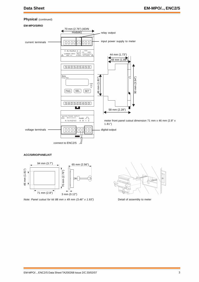
Physical (continued)
EM-MPO/SIRIO
ACC/SIRIO/PANELKIT
PAG SEL SET
SirioEnergy Meter
10Wh
C AL1AL2AL3 3 40V~ 230V~
115V~
POWER SUPPLY3VA~50/60Hz!
CURRENT INPUTMAX 7A ~
VL3VL1N VL2 A
V O L T A G E I N P U TM A X 4 5 0 V ~!
B 1 2Rs485
RELAY1A-250V~ !
connect to ENC2/S
voltage terminals
current terminals
relay output
digital output
Detail of assembly to meter
70 mm (2.76”) (4DINmodule)
meter front panel cutout dimension 71 mm x 46 mm (2.8” x1.81”)
58 mm (2.28”)
44 mm (1.73”)
48 mm (1.89”)
46 m
m (1
.81”
)
input power supply to meter
90 m
m (3
.54”
)
94 mm (3.7”)
71 mm (2.8”)
46 m
m (1
.81”
)
65 mm (2.56”)
70 m
m (2
.76”
)
3 mm (0.12”)
Note: Panel cutout for kit 88 mm x 49 mm (3.46” x 1.93”)

4 EM-MPO/.., ENC2/S Data Sheet TA200268 Issue 2/C 20/02/07
EM-MPO/.., ENC2/S Data Sheet
Physical (continued)
ENC2/S
1 2 3 4 5 6 7 8 9 10
TX RX
OK
1 2
~230V NC NO C
RDS/RS232 !24V
~
MODEM
SPCO relay (digital output)
RS232/485 converter
relay O/PLED
status LEDs
input LEDs
inputs
Trend LanLEDs
Trend Lanconnector
earth busaddress/baud rate switch
25 Way D type
9 Way D type
9 Way D type
connection to EM-MPO/..
230 mm (9.06”) 70 mm (2.76”)
210
mm
(8.2
7”)
230 Vacinput powersupply option
24 Vac or dcinput powersupply option
136 mm (5.35”)16 mm(0.63”)
33 m
m (1
.3”)
adaptor cable(3 m, 9’ 10”),supplied
adaptor cable(40 mm, 1.57”),supplied
33 mm (1.3”)

5EM-MPO/.., ENC2/S Data Sheet TA200268 Issue 2/C 20/02/07
Data Sheet EM-MPO/.., ENC2/S
FUNCTIONALITYThe EM-MPO/.. and the ENC2/S together provide electricitymeasurements which can be accessed by IQ system devices.The EM-MPO/.. takes the measurements and sends them to theENC2/S in standard RS485 interface protocol. ENC2/S storesthis data in memory and calculates further measurements. IQsystem devices can then read the measurements from theENC2/S using IQ system network communications.
EM-MPO/..
Front panelsAll EM-MPO/.. units have an LED display on which to display themeasured parameters, and to enable the unit to be configured.They also have three pushbuttons PAG, SEL, and SET.
PAG: This steps though the parameter types (e.g. V, A, W)SEL: This selects parameters within the type (e.g. forcurrent: Al, Aneutral, Alaverage)SET: This is used to configure the unit.PAG+SEL: This combination will enter configuration modeon the unit.
RS485 OutputThe unit provides a standard RS485 output to transmit themeasurements to the ENC2/S which can be up to 3 m away (setby default for ENC2/S communications)
ConfigurationAll EM-MPO/.. units have the following parameters configured bydefault with the correct settings for communication with theENC2/S. If they have been changed then they should be returnedto the following settings:
RS485 Baud Rate: 9600RS485 Parity: NoneRS485 Address (modbus): 1
All meters need to be configured to cater for:Voltage transformers (cannot be used on /SIRIO)Current transformersConnection type (e.g. 3 phase (delta), 3 phase +neutral(star), 2 phase with neutral, Single phase with neutral).
Configuration mode also enables the counters and the averagesto be reset.
The table below indicates the major differences between the 3meters.
EM-MPO/STAR3DIN
The EM-MPO/STAR3DIN is a DIN rail mounted high quality energyanalyser with a dot matrix LCD display. A mounting kit is availableto facilitate front panel mounting (ACC/STAR3DIN/PANELKIT)
Input Power SupplyThe EM-MPO/STAR3DIN requires 230 Vac (fused at 100 mAT)or 115 Vac (fused at 200 maT), 35 to 400 Hz, at 4VA.
ParametersIn addition to the parameters delivered to the ENC2/S, the unit candisplay:
Minimum Phase voltages Vln (V)Maximum Phase voltages Vln (V)Phase to Phase Voltages Vlx-Vly (V)Minimum Phase Currents (A)Maximum Phase Currents (A)Neutral Current (A) - Star onlyAverage Phase Currents (A)Maximum Demand Phase Currents (A)Total Maximum Demand Power (kW)Total Maximum Demand Apparent Power (kVA)Total Maximum Demand Reactive power (VAr)Positive 3 Phase Apparent Energy Counter (kVAh)Phase Voltage Total Harmonic Distortions (%)Total Voltage Total Harmonic Distortion (%)Phase Current Total Harmonic Distortions (%)Total Current Total Harmonic distortion (%)
ConnectionThe unit can be connected in the following configurations:
Single Phase with neutral (1CT)2 Phase with neutral (2CTs) Diphase3 Phase (3CTs) Delta3 Phase with Neutral (3CTs) Star3 Phase using 2 VTs (3CTs) Delta3 Phase using 2 CTs (2CTs) Delta
Voltage transformers can be used in all configurations, 1 VT foreach phase (except for 3 phase delta using 2 VTs)
ConfigurationThe following settings must be configured:RS485: Default baud rate and parity settings OK, see above.
Protocol must be changed from IEEE to ASCIIRS485 address (modbus): Default setting OK, see aboveVTs: If used must be set up. If not used set ratio to 1 (default)CTs: Must be set up.Connection: set up to one of the following:
Delta: 3 phase without neutralStar: 3 phase with neutralDiphase: 2 phase with neutralSingle-phase: 1 phase with neutral
The set up pages may also be used to:Set integration time for calculation of average current
and power (0 to 99 minutes, default 15 minutes)Reset energy countersReset averages and maximum demandsEnable/Disable cogeneration counters (note that to
measure cogeneration properly the CTs must be connected inthe same direction)
NID3RATS/ 3RATS/ OIRIS/
tnessretemaraPS/2CNEot
33 3323
esahP3ev-ton()ygrenE
sretemaraPnodeyalpsid
retem
dettimsnart3361sulp
dettimsnart3301sulp
7
ycaruccA:%5.0<
rewoP,I,V:%5.0<
rewoP,I,VI,V:%1
rewoP:%2
gnixiFliarNID
tiklenap()elbaliava
lenaptnorFliarNID
)elbaliavatiklenap(
stloVxaM
esahpcaV034lartuenot
esahpcaV006esahpot
rofsTVesU()stlovretaerg
esahpcaV034lartuenot
esahpcaV006esahpot
rofsTVesU()stlovretaerg
otesahpcaV462lartuen
otesahpcaV054esahp
sTV sey sey on
noitarenegoC sey sey on
yalpsiD DCLxirtamtoDtnemges-itlum
noderthgirbDCLkcalb
DCLtigid8
stuptuOlatigiD enon cinortcele2cinortcele1lacinahem1
noitpmusnoC AV4 AV4 AV3
ALL EM-MPO UNITS MUST HAVE THE RS485PROTOCOL CONFIGURED FOR ASCII
Their protocols are configured by default for IEEE,and must be changed to ASCII
ENC2/S Network
Supervisor

6 EM-MPO/.., ENC2/S Data Sheet TA200268 Issue 2/C 20/02/07
EM-MPO/.., ENC2/S Data Sheet
FUNCTIONALITY (continued)
EM-MPO/STAR3
The EM-MPO/STAR3 is a front panel mounted energy analyserwith a multi-segment bright red on black LCD display. It has twodigital outputs for measurement pulses, or alarm indication.
Input Power SupplyThe EM-MPO/STAR3 requires 230 Vac or 115 Vac, 35 to 400 Hz,at 4VA.
ParametersIn addition to the parameters delivered to the ENC2/S, the unit candisplay:
Phase to Phase Voltages Vlx-Vly (V)Neutral Current (A) - Star onlyAverage Phase Currents (A)Maximum Demand Phase Currents (A)Total Maximum Demand Power (kW)Total Maximum Demand Apparent Power (kVA)Phase Voltage Total Harmonic Distortions (%)Total Voltage Total Harmonic Distortion (%)Phase Current Total Harmonic Distortions (%)Total Current Total Harmonic distortion (%)
ConnectionThe unit can be connected in the following configurations:
Single Phase with neutral (1CT)2 Phase with neutral (2CTs) Diphase3 Phase (3CTs) Delta3 Phase with Neutral (3CTs) Star3 Phase using 2 CTs (2CTs) Delta
CTs must be used. VTs can be used in all configurations., 1 VTfor each phase.
ConfigurationThe following settings must be configured:RS485: Default baud rate and parity settings OK, see above.
Protocol must be changed from IEEE to ASCIIRS485 address (modbus): Default setting OK, see aboveVTs: If used must be set up. If not used set ratio to 1 (default)CTs: Must be set up.Connection: set up to one of the following:
Delta: 3 phase without neutralStar: 3 phase with neutralDiphase: 2 phase with neutralSingle-phase: 1 phase with neutral
The set up pages may also be used to:Set integration time for calculation of average currentand power (0 to 99 minutes, default 15 minutes)Reset energy countersReset averages and maximum demandsEnable/Disable cogeneration counters (note that tomeasure cogeneration properly the CTs must beconnected in the same direction)
Alarm Outputs: The two alarm outputs can be set to either:100 ms pulse mode20 ms pulse modeRelay mode
This setting applies to both outputs, they cannot be set individually.
Pulse ModesThe outputs can be set individually to be sourced from one of thefollowing parameters:
+ve 3 Phase Active Energy consumed (kWh)-ve 3 Phase Energy (kWh)+ve 3 Phase Reactive Energy (kVArh)-ve 3 Phase Reactive Energy (kVArh)3 Phase Apparent Energy (kVAh)
Each output also requires the value (‘weight’) of each pulse tobe defined (e.g. 0.01 kWh/pulse)
Relay ModeNote that it is possible to configure relay 1 to be controlled from theRS485 bus, but this feature is not available when the ENC2/S isconnected.
The outputs can be set individually to indicate an alarm conditionfrom one of the following parameters: Total Voltage or PhaseVoltage, VLN, (V)
Total Current or Phase Current, ALN, (A)Total Power or Phase Power (W)Total Apparent Power or Phase Apparent Power (VA)Total Reactive Power or Phase Reactive power (VAr)Total Power Factor or Phase Power Factor (cos ø)Total THD voltage or Phase THD voltage (%)Total THD current of Phase THD current (%)
When used as an alarm indication each output should be configuredwith the following settings:
High alarm thresholdLow Alarm thresholdHysteresis:The alarm condition is registered only if the value risesabove the threshold by the percentage setDelay: The alarm condition is registered only if the alarmpersists for longer than the alarm delay (000 to 999 s)

7EM-MPO/.., ENC2/S Data Sheet TA200268 Issue 2/C 20/02/07
Data Sheet EM-MPO/.., ENC2/S
FUNCTIONALITY (continued)
EM-MPO/SIRIO
The EM-MPO/SIRIO is a DIN rail mounting multiparameter meterwith an 8 digit LCD display.
Input Power SupplyThe EM-MPO/SIRIO requires 230 Vac or 115 Vac, 35 to 400 Hz,at 3 VA
ParametersIt displays the following parameters:
Mean Line Voltage (V)Main Phase Current (I)Total Active Power (W)Total Power factor (Cos ø)Average Active Power (W)Maximum Demand Active Power (W)Active Energy Counter (Wh)
The display selection is slightly different to the previous twometers.The PAG key steps though three display pages, Voltage/Current,Active Power/Power Factor, and Active Energy Counter. Withthe Active Power/Power Factor selected, pressing the SEL keysteps through the other pages, Average Active Power, Max.Dem. Active Power, and back to Active Power/Power Factor.The EM-MPO/SIRIO cannot supply the -ve 3 Phase Energy(node 58) parameter to the ENC2/S.
ConnectionsIt can be connected in the following configurations:
Single Phase with Neutral (1CT)2 Phase with Neutral (2CTs) Diphase3 Phase (3CTs) Delta3 Phase with Neutral (3CTs) Star3 Phase using 2CTs (2CTs) Delta
It cannot use VTs.
ConfigurationThe following settings must be configured:RS485: Default baud rate and parity settings OK, see above.
Protocol must be changed from IEEE to ASCIIRS485 address (modbus): Default setting OK, see aboveCTs: Must be set up.Connection: set up to one of the following:
Delta: 3 phase without neutralStar: 3 phase with neutralDiphase: 2 phase with neutralSingle-phase: 1 phase with neutral
The set up pages may also be used to:Set integration time for calculation of average currentand power (0 to 99 minutes, default 15 minutes)Reset energy countersReset averages and maximum demands
Alarm Outputs: The EM-MPO/SIRIO has two alarm outputs, onemechanical (1 A, 250 V) and one electronic (120 mA, 100 Vac).The two alarm outputs can be set to either:
100 ms pulse mode20 ms pulse modeRelay mode
This setting applies to both outputs, they cannot be set individually.
Pulse ModesThe outputs can be set individually to be sourced from one of thefollowing parameters:
3 Phase Active Energy consumed (kWh)3 Phase Apparent Energy (kVAh)
Each output also requires the value (‘weight’) of each pulse tobe defined (1, 10, or 100/pulse)
Relay ModeThe outputs can be set individually to indicate an alarm conditionfrom one of the following parameters:
Total Current (A)Total Voltage (V)Total Power (W)Total Power Factor (cos ø)
The mechanical alarm output can be set to either produce a leveloutput, or a pulse output (e.g. to trip an external contactor) underalarm conditions.
Each relay mode output should be configured with the followingsettings:
High alarm thresholdLow Alarm thresholdHysteresis: The alarm condition is registered only if thevalue rises above the threshold by the percentage setDelay: The alarm condition is registered only if the alarmpersists for longer than the alarm delay (000 to 999 s)

8 EM-MPO/.., ENC2/S Data Sheet TA200268 Issue 2/C 20/02/07
EM-MPO/.., ENC2/S Data Sheet
FUNCTIONALITY (continued)
ENC2/S
The ENC2/S allows an EM-MPO/... to be connected to the IQ system network. It stores values received from the meter, making themavailable to other devices on the IQ system network. Some values are calculated within the ENC2/S using readings received fromthe meter.
The ENC2/S consists of a customised IQ22x controller with an RS232/RS485 converter module connected to the specially modifiedRS232 port, and a dedicated script program (TCL) which performs the necessary communications and calculations to produce themeasurements in the IQ controller analogue array. It also has further modules configured so that some of the measurements areidentified by label and additional measurements are calculated within the ENC2/S.
Hardware
Unit: The ENC2/S is supplied in a plastic enclosure with atransparent plastic flip-up terminal cover. It has a 3 point mountingto facilitate installation. It has an RS232/RS485 converterconnected by cable to the RS232 connector at the rear of the unit.
Connectors: Two part connectors are used throughout tofacilitate wiring. A busbar is provided for screen termination.
Power: 230 Vac 50/60 Hz (/230 option), 24 Vac or 24 Vdc (/24option).
Fusing: The controller has no replaceable fuses; protection isprovided by a self-resetting thermally protected transformer.
Indicators: LED indicators for receive and transmit networkcurrent flow (RX, TX) and network OK ( ), also for all I/Ochannels, power ( ), and watchdog ( ). See specificationsection for details.
Network: The 2 part network terminals facilitate connectionof 2 wire cables.
Address Switch : The ENC2/S device address on the localLan is selected by address switch poles 1 to 7. The TCL programrequires that the next address (i.e. address switch setting plus1) is also allocated to the ENC2/S. Therefore the address switchmay only be set in the range 4 to 8, 11 to 118 and both the settingand the setting plus 1 must be unique on the local Lan.
Baud Rate Switch : The local Lan baud rate is set by addressswitch poles 8 to 10 to 19k2, 9k6, or 1k2. The local Lan baud ratemust be set to match other nodes on the local Lan.
Network bypass relay: In order that the network continues tooperate if the ENC2/S fails, a node bypass relay is fitted tomaintain network integrity in the event failure of the node'spower supply, or failure of the node itself. The bypassing of anode will be recognised by the downstream node, and reportedas a Lan Changed alarm.
Battery Backup: Details about the strategy configuration, timeand date, and logged data are stored in RAM. A plug-in lithiumcell provides power to maintain the data in the event of powerfailure, or the controller being switched off.
RS485 to EM-MPO/..: The RS232/RS485 converter module isconnected to the rear of the unit by means of a 40 mm 25 wayfemale D connector to 9 Way male D connector cable. Theconverter module is connected to the EM-MPO/.. by a 3 meterunscreened 9 way male D connector to open ends 2 wire cable.Both of these adapter cables are supplied with the unit.
The interface module has DIP switches which are set by defaultto operate correctly with the ENC2/S EM-MPO/.. system. Theyshould not be changed. They are set as follows:
Note: The internal wiring to the rear RS232 plug is non-standardand is only intended for the ENC2/S application. If any otherdevice were to be connected to this plug, damage may occur.
I/O channels: The ENC2/S is supplied with 2 digital inputchannels, and 1 digital (relay) output channel.
Digital (Relay) Output(external channel unnumbered, configuration channel OP8)
Digital only inputs(external connection inputs and configuration channels 1,2)
eloP gnitteS noitcnuF
1WS NO eriw2
2WS FFO NEXR
3WS FFO NEXT
4WS NO 2EDA
5WS FFO 1EDA
6WS FFO 0EDA
� �
� � � � � �
� �
� � �
� �
�
� �
� �
cut ends
ENC2/S EM-MPO/..
40 mm (1.57”)25 W D female
9 W D male9 W D male
3 m (9’ 10”)
RS232 to RS485 Converter

9EM-MPO/.., ENC2/S Data Sheet TA200268 Issue 2/C 20/02/07
Data Sheet EM-MPO/.., ENC2/S
COMPATIBILITY
Supervisors: 916, 963, IQView, Viewpoint.Utility software: PowerTool, Wupdn, SET.Controllers: It can communicate to other IQ controllers
using inter-controller communications.
Strategy files: A certain amount of configuration is present inthe ENC2/S so if a strategy file is downloaded into the ENC2/S,the pre-configured data will be lost. The IQ ConfigurationReference Manual Addendum covers the compatibility betweendifferent types of strategy files.
Sensor Logs: The IQ Configuration Reference ManualAddendum covers the compatibility between the ENC2/S sensorlogs and supervisors and software tools.
Compatibility of EM-MPO/.. and ENC2/S with EM/MPO2 andEM/MPO+: The ENC2/S no longer sends current time to the meter(i.e. meter timer has to be set manually using front panel buttons).The following additional values are on longer received from theEM-MPO/.. meters:
Note that using the current nomenclature: Red Phase ≡ L1,Yellow Phase ≡ L2, Blue Phase ≡ L3.
Compatibility of EM-MPO/... and EM/MPO2 with EM/MPO+:The EM/MPO+ has a fibre optic connection which is onlycompatible with ENC.The EM/MPO2 is compatible with ENC2 and ENC2/S.The EM/MPO is only compatible with ENC/S.By comparison with the older meters the parameter valuesreceived from the EM/MPO meters have different units as follows:sensors 3, 11,12,13, are W instead of kW, and sensors 14 and15 are now VA and VAr instead of kVA and kVAr. The ranges(i.e. maximum values that parameters can take) available in theEM-MPO/.. and EM/MPO2 are much larger than those on theEM/MPO+.
Compatibility with old RS232/485 converter: The old greyconverter (K485-ADE) plugged directly into the back of theENC2/S using its 25 Way D type). It can be plugged into the newENC2/S but its old cable (9 Way D female to cut ends, 2 wire,EJ104355) must be used to connect to the EM-MPO/.., or EM-MPO2.
FIRMWARE
The firmware within the ENC2/S consists of two parts: thedevice part, and the TCL part. The device part (standard IQ2v3.1firmware) consists of a number of standard IQ systemconfiguration modules, and functions in exactly the same wayas an IQ Controller. Some of these modules are alreadypre-configured as explained in the strategy section. The remainingmodules may be configured in the normal way. The TCL part runsthe TCL script which communicates with the EM-MPO/.., performsnecessary calculation, and places the reading into the analoguearray.
Configuration: The device part of the ENC2/S uses the standardIQ configuration mode which enables configuration across thenetwork. Alternatively SET can be used but the existing specialstrategy should first be uploaded before adding to it using SET.The modified strategy can then be downloaded to the controllerby SET. SET can also be used to upload, and download IQ2 filesfor backup purposes.
Communications: The ENC2/S is connected to IQ systemdevices by way of the IQ system current loop network, and tothe EM-MPO/.. by way of an RS485 link.
Modules: The strategy within the device part consists of a numberof individual functional blocks known as configuration modules.These blocks can be linked in various combination to performmanipulation of parameters from the EM-MPO/.. and to service theI/O. The table lists the different types of configuration modules andthe number of each type available within the ENC2/S.
Full details of the modules are given in the IQ ConfigurationManual and Addendum. The ENC2/S contains the normal IQ2features as described in IQ Configuration Manual Addendum:Engineers Journal (J), I/O Summary (i/o) Loader Issue (R(c), ’c’lower case), Serial Number (R(s), ‘s’ lower case), SupplyFrequency Option, Enhanced Logging, Module positions, andStrategy Cleardown.
Differences between the modules covered in the manuals andthe ENC2/S’s modules are described below:
Address module: The address module has a 'sUpervisor portaddr' parameter which is ignored because the port is used forconnection to the EM-MPO/...
TCL port: This is pre-configured in the ENC2/S to communicatewith the EM-MPO/...
edoN lebaL egnaR stinU
24 rotcaFtserCtnerruCesahPdeR 01-0
34 rotcaFtserCtnerruCesahPwolleY 01-0
44 rotcaFtserCtnerruCesahPeulB 01-0
95 ygrenEevitcaeRhP3ev- 0000023-0 hrAVk
06 snoCygrenEesahPeulB 0000023-0 hWk
epyTeludoM rebmuN epyTeludoM rebmuN
rosneS 23 mralAlacitirC 4
epytrosneS 8 yrotsiHmralA 02
pooL 61 smmoCCI 61
noitcnuF 09 stupnIlatigiD 23
cigoL 09 ecneuqeStsaF 8
revirD 21 enoZ 5
bonK 03 eludehcS 8
hctiwS 02 radnelaC 02
golrosneS 02 drowssaPresU 6
petsecneuqeS 042 emitecneuqeS s1
sedoNeugolanA 552 sedoNlatigiD 505

10 EM-MPO/.., ENC2/S Data Sheet TA200268 Issue 2/C 20/02/07
EM-MPO/.., ENC2/S Data Sheet
STRATEGY
The strategy is pre-configured, partially by the TCL script, andpartially by module configuration.
Strategy Items (Inputs, Knobs, Switches)
I9, Meter Comms Fail: The TCL part sets digital input 9 toindicate the meter communication state; (0 = No data receivedfrom meter in previous minute, 1 = meter present). I9 generatesthe alarm "Meter Comms Fail" when it changes to state 0. The failcondition is detected by the strategy (byte 32 bit 0) and it setsall readings from the meter to zero, and any derived values (i.e.sensors 21 to 29) are not incremented.Note that care should be taken in interpreting calculated valuesafter communication failure due to the way they are calculated.
I1, W1, K1, Demand Period Synchronisation: The demandperiod is set to a half hour by default. The start of the period isnormally synchronised to an internal half hour pulse (W1=0), butthere is an option to use an external contact closure connectedto input 1 (I1) by setting W1 to 1. If the internal pulse is used, itcan be delayed by K1 by up to 29 m, 59 s, to synchronise withthe electricity meter. The start of the period zeroes the kWh, kVA,and kVArh consumed in the half hour.
W2, Max. Demand Reset: The half hour maximum demandvalues (kVA, kW, kVAr) are reset by setting W2 to 1.
W3,Totalisor Reset: The totalised values (MWh, MVAh, MVArh)are reset by setting W3 to 1
Sensors and NodesSensor units and labels are set up as shown in the sensor tablebelow.
Note that the units can only be up to four characters long, thus asMVArh and kVArh are 5 characters long, the last character (h) islost. This is indicated by (h) in the tables.Note that if both V and A are at maximum range, then themaximum kW will be exceeded.The TCL part receives the EM-MPO/.. values and places them intoanalogue nodes 1 to 16, and 33 to 58 (excluding 42 to 44 and 47to 52). Sensors 1 to 16 monitor nodes A1 to A16 directly.Sensors 17 to 29 monitor values calculated by the strategymodules.
The values placed into nodes A33 to A60 by TCL are shown inthe nodes table below.
Note that L1, L2, L3 were previously referred to as red, yellow,blue phases respectively.Note that Node 58 -ve 3 Phase Energy is not available fromEM-MPO/SIRIO; the value will be set to zero.Analogue nodes do not have labels or units so these would haveto be set up in the supervisor.Sensors 17, 18, 19, 20 are set to the values of nodes 45, 46 ,56, 57 respectively divided by 1000 (e.g. converting kWh intoMWh, and VA into kVA).Sensors 21, 22 measure active, and reactive energy consumedin a half hour by monitoring the changes in nodes 45 and 46respectively. Sensor 25 measures apparent energy consumedin a half hour by integrating sensor 14 and dividing by 1000.Sensors 21, 22, 25 are reset to zero at the beginning of each halfhour period by the synchronisation pulse.Sensors 23, 24, 26 measure apparent, active, and reactive,half hour maximum demand by keeping the maximum values ofsensors 25, 21, and 22 respectively (multiplied by 2 to give fullpower units e.g kW). They are reset to zero by W2.Sensors 27, 28, 29 keep totalised values of sensors 3, 15 and14 (divided by 1 million) respectively; they are reset to zero byW3.Nodes 45, 46, 56, 57 and 58 can be reset to zero by EM-MPO/..configuration (see appropriate meter manual).Node 58 will only give negative energy (i.e. power generationback into input power supply) if Cogeneration (COG) is set byEM-MPO/.. configuration (see appropriate meter manual).The definitions of the measurements (e.g. power peaks) aregiven in the appropriate meter manual.
Plotting Channels
Items Label UnitsItems Label Units Default Note
Inputs I1 Ext Max Dem Sync Pls 0 Sync on contact closure if W1=1
I9 Meter Comms Fail 00=no data received,1=meter present
SwitchesW1 Enable Ext Sync 0
Sync max demand either from I1(W1=1) or internal timing pulse(W1=0)
W2 Max Demand Reset 0W2=1 resets 0.5 Hr maximumdemand (kW, kVA, kVAr)
W3 Totalisor Reset 0W3=1 resets totalisors (MWh,MVAh, MVAr usage)
KnobsK1 Int pulse time delay Sec 0
Sets delay on internal pulseused for max demand sync ifW1=0 (range 0 to 1799)
srosneS noitpircseD slennahCtolP doireP sdrocerfooN
61ot1 elbatees 61ot1 nim1 0001
12 rhflahnisnochWk 91 snim03 0001
22 rhflahnisnochraVk 71 snim03 0001
52 rhflahnisnochAVk 81 snim03 0001
82 egasUhrAVM 02 snim03 0001
rosneS lebaL egnaR stinU
1 VesahPoTesahPnaeM 00023-0 V
2 tnerruCesahPgvA 00023-0 A
3 rewoPevitcA 0000023-0 W
4 ihPsoCrotcaFrewoP 1+ot1-
5 egatloV1L 00023-0 V
6 egatloV2L 00023-0 V
7 egatloV3L 00023-0 V
8 tnerruC1L 00023-0 A
9 tnerruC2L 00023-0 A
01 tnerruC3L 00023-0 A
11 rewoP1L 0000023-0 W
21 rewoP2L 0000023-0 W
31 rewoP3L 0000023-0 W
41 rewoPtnerappA 0000023-0 AV
51 rewoPevitcaeR 0000023-0 rAV
61 ycneuqerF 09-02 zH
71 snoCygrenEevitcA 0000023-0 hWM
81 snoCygrenEevitcaeR 0000023-0 )h(rAVM
91 skaePrewoPtnerappA 0000023-0 AVk
02 skaePrewoPevitcA 0000023-0 Wk
12 rHflaHnisnochWk 0000023-0 hWk
22 rHflaHnisnochrAVk 0000023-0 )h(rAVk
32 dnameDxaMrHflaHAVk 0000023-0 AVk
42 dnameDxaMrHflaHWk 0000023-0 Wk
52 rHflaHnisnochAVk 0000023-0 hAVk
62 dnameDxaMrHflaHrAVk 0000023-0 rAVk
72 egasUhWM 0000023-0 hWM
82 egasUhrAVM 0000023-0 )h(rAVM
92 egasUhAVM 0000023-0 hAVM
edoN lebaL egnaR stinU
33 ihPsoCrotcaFrewoP1L 1+ot1-
43 ihPsoCrotcaFrewoP2L 1+ot1-
53 ihPsoCrotcaFrewoP3L 1+ot1-
63 rewoPevitcaeR1L 0000023-0 rAV
73 rewoPevitcaeR2L 0000023-0 rAV
83 rewoPevitcaeR3L 0000023-0 rAV
93 rewoPtnerappA1L 0000023-0 AV
04 rewoPtnerappA2L 0000023-0 AV
14 rewoPtnerappA3L 0000023-0 AV
x
54 .snoCygrenEevitcAesahP3ev+ 0000023-0 hWk
64 ygrenEevitcaeR.hP3ev+ 0000023-0 )h(rAVk
x
35 rewoPevitcaeRgvAesahP3 0000023-0 rAV
45 rewoPtnerappAgvAesahP3 0000023-0 AV
55 rewopevitcAgvAesahP3 0000023-0 W
65 skaePrewoPtnerappAesahP3 0000023-0 AV
75 skaePrewoPevitcAesahP3 0000023-0 W
85 ygrenEesahP3ev- 0000023-0 hWk
Sensor Table
Nodes Table

11EM-MPO/.., ENC2/S Data Sheet TA200268 Issue 2/C 20/02/07
Data Sheet EM-MPO/.., ENC2/S
G6D
Comms fail interlock timerTo Pages(s) 5,7,8,
48
G11
COUNTER
S
A
R
M
I1V
F39D 9 9 9
93
94
Scale Factor 10
49
F39
HYST BAND
E
G
F
D
5
G11R
8
179,0I1
EXTERNAL
S 1,0
Ext Max Dem Sync Pls
50
G1
TIMER
S D493,221,0
Off Delay 0
51
G2
COMB
E
F
G
H
D
G3D
G1D
0,0
0,0
J orK orL orM
21,1
J = E f
52
G3
COMB
E
F
G
H
D
G1D
0,0
0,0
0,0
J orK orL orM
21,2
J = E
493,2Timing Pulse 30 Minutes
53
G4
COMB
E
F
G
H
D
F39D
G2D
W1V
0,0
J orK orL orM
21,3
J = E G K = F g
W1SWITCH
S 18,0
Enable Ext SyncPin Level 90Status 0
G4D
Ext. or Int. Sync. PulseTo Pages(s) 4,6,7,
K1ADJ KNOB
V 221
Int pulse time delayUnits SecAdjustment Id G1FPin Level 90Top of Range 1799Bottom of Range 0Value 0
The above is set for internal 30 min. maximum demand periods using bit 493,2.However it is possible to amend this to 15 min. periods (using 493,1) or 60 min. (using 493,3).N.B. Knob 1 and it’s upper limit should be amended accordingly.Consideration should also be given to Maximum Demand scaling calculations and certain Sensor labels if time intervals other than 30 min. are used. 54
G5
COMB
E
F
G
H
D
I9V
0,0
0,0
0,0
J orK orL orM
21,4
J = E
I9V 2,0Meter Comms Fail
From Page 2
55
G6
TIMER
S DG5D32,0
On Delay 2
66
F5
GATE
D = F when B = 1
E
F
B
D
G4D
F4D
49105
49Default = 0
G4D 21,3Ext. or Int. Sync. Pulse
From Page 3
24
S21
INTERNAL
S VF46D
21
kWh cons in Half HrUnits kWh
P19PLOT
Sensor 21Period 30 Min
67
F6
MULTIPLY
D=GxExF
E
G
F
D
2
F5D
1
106
68
F7
MAXIMUM
E
F
G
H
D
F6D
F6D
F8D
F8D
107
69
F8
GATE
D = F when B = 1
E
F
B
D
G8D
F7D
49108
70
G7
TIMER
S DG8D21,6
On Delay 1
71
G8
COMB
E
F
G
H
D
G7D
G8D
0,0
0,0
J orK orL orM
W2V
J = e F
W2SWITCH
S 18,1
Max Demand ResetPin Level 90Status 0
49Default = 020
S17
INTERNAL
S VF9D
17
Active Energy ConsUnits MWh
72
F9
DIVIDE
D=F(G/E)
E
G
F
D
1000
45
1
109
27
S24
INTERNAL
S VF8D
24
kW HalfHr Max DemandUnits kW
62
F1
ADD/SCLR
D = (E * G) + (F * H)
E
F
G
H
D
1
-1
F3D
F2D
101
63
F2
MULTIPLY
D=GxExF
E
G
F
D
1
F3D
1
102
61
F3
GATE
D = F when B = 1
E
F
B
D
G6D
F2D
4510345
+ve 3 Phase Energy Cons from TCL (kWh)
G6D 32,0Comms fail interlock timer
From Page 3
64
F4
ADD/SCLR
D = (E * G) + (F * H)
E
F
G
H
D
1
1
F1D
F5D
104
65
F46
GATE
D = F when B = 1
E
F
B
D
G4D
F46D
F5D146
STRATEGY
Schematics
The maximum demand period is based on the 30 minute timing pulse bit 493,2. As indicated in fig 1, the period could be changed to a 15 m or 60m period. Knob 1 (K1) sets a delay (0 to 1799 s, 29 m 59 s) on the standard timing pulse to specify the start of the maximum demand period. Thisis done by a combination of logic modules G1, G2, and G3. G1 produces the delay on the falling edge of the timing pulse as specified by K1. G2and G3 together then produce a 1s pulse at the end of the delayed pulse. Logic module G4 then allows switch 1 (W1) to select either this pulse, oran external synchronisation pulse connected by way of digital input 1 (I1). G11 and F39 are used to ensure that the input to G4 remains set for onesequence cycle, so that G4 will gate it through if appropriate. The meter communication state is indicated by I9; if I9=1, meter communications areOK. This is filtered by G6 so that it must stay OK for 2 secs for it to set bit 32,0. This bit is used to add zero to the power values (W, VA, VAr) andzero increment to energy consumed values (Wh, VArh) while the meter communications are faulty.
In Fig 2., the meter input on node 45 (Positive 3 phase Active Energy Consumed - kWh) is divided by 1000 by F9 to give Active Energy Cons (MWh)which is monitored by S17. F2 is serviced after F3 and F1, so its output holds the previous value of node 45. F3 normally gates through the meterinput on node 45, but gates through the previous value from F2 if there is a communications failure with the meter. F1 takes the previous value ofnode 45 from the current value so that the increase in value can be added into the accumulating total by function module F4. F46 is serviced beforeF5, so when the sync pulse occurs F46 passes the total through to S21, and F5 then passes through zero which clears the total for the start of thenext period. The total, 'kWh cons in Half Hr' is monitored by S21; it will only show the total accumulated before the last sync pulse.F6 multiplies the half hour consumption by two to give a true kW power value. F7 passes this value through if it is greater than the previous maximumheld by the F7/F8 combination. This produces the 'kW HalfHr Max. Demand' which is monitored by S24. Switch 2 (W2), the Maximum Demand Reset,is inserted between modules G8 and G7 which ensure that the switch is set back to zero after one cycle of the sequence table. W2 causes F8 to gatethrough zero which resets the kW HalfHr Max. Demand.
Fig 1. Sync. pulse generation
Fig 2. kW Half Hour Maximum Demand

12 EM-MPO/.., ENC2/S Data Sheet TA200268 Issue 2/C 20/02/07
EM-MPO/.., ENC2/S Data Sheet
77
F10
GATE
D = F when B = 1
E
F
B
D
G6D
49
S3V110
78
F11
DIVIDE
D=F(G/E)
E
G
F
D
1000000
F10D
1
111
79
F12
ADD/SCLR
D = (E * G) + (F * H)
E
F
G
H
D
0.00028
1
F11D
F13D
112
80
F13
GATE
D = F when B = 1
E
F
B
D
G10D
F12D
49113
81
G9
TIMER
S DG10D22,0
On Delay 1
82
G10
COMB
E
F
G
H
D
G9D
G10D
0,0
0,0
J orK orL orM
W3V
J = e F
W3SWITCH
S 18,2
Totalisor ResetPin Level 90Status 0
49Default = 0
S3VActive PowerFrom Page 2
G6D 32,0Comms fail interlock timer
From Page 3 49Default = 0
30
S27
INTERNAL
S VF13D
27
MWh UsageUnits MWh
Fig 3. MWh Usage
88
F14
GATE
D = F when B = 1
E
F
B
D
I9V
49
S14V114
89
F15
DIVIDE
D=F(G/E)
E
G
F
D
1000
F14D
1
115
90
F16
ADD/SCLR
D = (E * G) + (F * H)
E
F
G
H
D
0.00028
1
F15D
F17D
116
91
F41
GATE
D = F when B = 1
E
F
B
D
G4D
F41D
F17D141
92
F17
GATE
D = F when B = 1
E
F
B
D
G4D
F16D
49117
93
F18
DIVIDE
D=F(G/E)
E
G
F
D
1000
F15D
1
118
94
F19
ADD/SCLR
D = (E * G) + (F * H)
E
F
G
H
D
0.00028
1
F18D
F20D
119
95
F20
GATE
D = F when B = 1
E
F
B
D
W3V
F19D
49120
96
F21
MULTIPLY
D=GxExF
E
G
F
D
2
F17D
1
121
97
F22
MAXIMUM
E
F
G
H
D
F21D
F21D
F23D
F23D
122
98
F23
GATE
D = F when B = 1
E
F
B
D
W2V
F22D
49123
S14VApparent Power
From Page 2
49Default = 0
I9V 2,0Meter Comms Fail
From Page 249
Default = 0
G4D 21,3Ext. or Int. Sync. Pulse
From Page 3
28
S25
INTERNAL
S VF41D
25
kVAh cons in Half HrUnits kVAh
P18PLOT
Sensor 25Period 30 Min
32
S29
INTERNAL
S VF20D
29
MVAh UsageUnits MVAh
49Default = 0
W3V 18,2Totalisor Reset
From Page 5
26
S23
INTERNAL
S VF23D
23
kVA HalfHrMax DemandUnits kVA
49Default = 0
W2V 18,1Max Demand Reset
From Page 4
Fig 4. kVA Half Hour Maximum Demand
Schematics (continued)
In Fig. 3, F10 will normally gate through S3, Active Power (W), but if the meter communications fail, it will gate through zero. The active power is dividedby 1,000,000 by F11, and then multiplied by 0.00028 (divided by 3600 - correct to 5 places after decimal point) within F12. The division by 3600 isto convert the MW value into MWh consumed per second, and then F12 and F13 together add this to the usage total every second to produce thetotalised MWh Usage monitored by S27. Switch 3 (W3), the Totalisor Reset, is inserted between modules G10 and G9 which ensure that the switchis set back to zero after one cycle of the sequence table. W3 causes F13 to gate through zero which resets the MWh Usage.
In Fig. 4, F14 will normally gate through S14, Apparent Power (VA), but if the meter communications fail, it will gate through zero. The active poweris divided by 1000 by F15, and then multiplied by 0.00028 (divided by 3600 - correct to 5 places after decimal point) within F16. The division by 3600is to convert the kVA value into kVAh consumed per second, and then F16 and F17 together add this in to the accumulating kVAh total every second.F41 is serviced before F17, so when the sync pulse occurs F41 passes the total through to S25, and F17 then passes through zero which clears thetotal for the start of the next period. The total, 'kVAh cons in Half Hr' is monitored by S25; it will only show the total accumulated before the last syncpulse.The apparent power from F15 (kVA) is divided by 1000 by F18 and then multiplied by 0.00028 (divided by 3600 - correct to 5 places after decimalpoint) within F19. The division by 3600 is to convert the MVA value into MVAh consumed per second, and then F19 and F20 together add this in tothe usage total every second to produce the totalised MVAh Usage monitored by S29. Switch 3 (W3), the Totalisor Reset, causes F20 to gate throughzero which resets the MVAh Usage.F21 multiplies the half hour consumption by two to give a true kVA power value. F22 passes this value through if it is greater than the previous maximumheld by the F22/F23 combination. This produces the 'kVA HalfHrMax Demand' which is monitored by S23. Switch 2 (W2), Maximum Demand Reset,causes F23 to gate through zero which resets the kVA HalfHrMax Demand.

13EM-MPO/.., ENC2/S Data Sheet TA200268 Issue 2/C 20/02/07
Data Sheet EM-MPO/.., ENC2/S
107
F24
ADD/SCLR
D = (E * G) + (F * H)
E
F
G
H
D
1
-1
F26D
F25D
124
108
F25
MULTIPLY
D=GxExF
E
G
F
D
1
F26D
1
125
106
F26
GATE
D = F when B = 1
E
F
B
D
G6D
F25D
4612646
+ve 3 Ph. Reactive Energy from TCL (kVArh)
G6D 32,0Comms fail interlock timer
From Page 3
109
F27
ADD/SCLR
D = (E * G) + (F * H)
E
F
G
H
D
1
1
F24D
F28D
127
110
F42
GATE
D = F when B = 1
E
F
B
D
G4D
F42D
F28D142
111
F28
GATE
D = F when B = 1
E
F
B
D
G4D
F27D
49128
112
F29
MULTIPLY
D=GxExF
E
G
F
D
2
F28D
1
129
113
F30
MAXIMUM
E
F
G
H
D
F29D
F29D
F31D
F31D
130
114
F31
GATE
D = F when B = 1
E
F
B
D
W2V
F30D
49131
49Default = 0
W2V 18,1Max Demand Reset
From Page 4
49Default = 0
G4D 21,3Ext. or Int. Sync. Pulse
From Page 3
115
F32
DIVIDE
D=F(G/E)
E
G
F
D
1000
46
1
132
21
S18
INTERNAL
S VF32D
18
Reactive Energy ConsUnits MVAr
25
S22
INTERNAL
S VF42D
22
kVArh cons in HalfHrUnits kVAr
P17PLOT
Sensor 22Period 30 Min
29
S26
INTERNAL
S VF31D
26
kVAr HalfHrMaxDemandUnits kVAr
Fig 5. kVAr Half Hour Maximum Demand
120
F33
GATE
D = F when B = 1
E
F
B
D
G6D
49
S15V133
121
F34
DIVIDE
D=F(G/E)
E
G
F
D
1000000
F33D
1
134
122
F35
ADD/SCLR
D = (E * G) + (F * H)
E
F
G
H
D
0.00028
1
F34D
F36D
135
123
F36
GATE
D = F when B = 1
E
F
B
D
W3V
F35D
49136
124
F37
DIVIDE
D=F(G/E)
E
G
F
D
1000
56
1
137
125
F38
DIVIDE
D=F(G/E)
E
G
F
D
1000
57
1
138
S15VReactive Power
From Page 2
49Default = 0
G6D 32,0Comms fail interlock timer
From Page 349
Default = 0
W3V 18,2Totalisor Reset
From Page 5
31
S28
INTERNAL
S VF36D
28
MVArh UsageUnits MVAr
P20PLOT
Sensor 28Period 30 Min
563 Phase Apparent Power Peaks from TCL (VA)
573 Phase Active Power Peaks from TCL (W)
22
S19
INTERNAL
S VF37D
19
Apparent Power PeaksUnits kVA
23
S20
INTERNAL
S VF38D
20
Active Power PeaksUnits kW
Fig 6. MVArh Usage
Schematics (continued)
In Fig 5., the meter input on node 46 (Positive 3 phase Reactive Energy Consumed - kVArh) is divided by 1000 by F32 to give Reactive EnergyCons (MVArh) which is monitored by S18. F25 is serviced after F26 and F24, so its output holds the previous value of node 46. F26 normally gatesthrough the meter input on node 46, but gates through the previous value from F25 if there is a communications failure with the meter.F24 takes theprevious value of node 46 from the current value so that the increase in value can be added into the accumulating total by function module F27.F42 is serviced before F28, so when the sync pulse occurs F42 passes the total through to S22, and F28 then passes through zero which clears thetotal for the start of the next period. The total, 'kVArh cons in HalfHr', is monitored by S22; it will only show the total accumulated before the lastsync pulse.F29 multiplies the half hour consumption by two to give a true kVAr power value. F30 passes this value through if it is greater than the previous maximumheld by the F30/F31 combination. This produces the 'kVAr HalfHrMaxDemand' which is monitored by S26. Switch 2 (W2), Maximum Demand Reset,causes F31 to gate through zero which resets the kVAr HalfHrMaxDemand.
In Fig. 6, F33 will normally gate through S15, Reactive Power (VAr), but if the meter communications fail, it will gate through zero. The active poweris divided by 1000,000 by F34, and then multiplied by 0.00028 (divided by 3600 - correct to 5 places after decimal point) within F35. The divisionby 3600 is to convert the MVAr value into MVArh consumed per second, and then F35 and F36 together add this to the usage total every secondto produce the totalised MVArh Usage monitored by S28. Switch 3 (W3), the Totalisor Reset causes F36 to gate through zero which resets the MVArhUsage.F37 takes the 3 Phase Apparent Power Peaks (VA) from node 56 and divides by 1000 to produce the Apparent Power Peaks (kVA) monitored by S19.F38 takes the 3 Phase Active Power Peaks (W) from node 57 and divides by 1000 to produce the Active Power Peaks (kW) monitored by S20.
Strategy Version:
Attribute K in the Address module is set to the strategy version number.

14 EM-MPO/.., ENC2/S Data Sheet TA200268 Issue 2/C 20/02/07
EM-MPO/.., ENC2/S Data Sheet
INSTALLATIONCONNECTIONS
EM-MPO/STAR3DIN
� � � � � � � � �
� � � �
� �
� �
PAG
SEL
SET
STAR3 din
10Wh
MULTI PANEL METER
Meter Input Power Supply
Single part screw terminals.
230 Vac +15 % -20 %,35 to 400 Hz, 4VA Supply
115 Vac +15 % -20 %,35 to 400 Hz, 4VA Supply
LN
E
230 Vac
100 mA T
4VA~ 50/60HzPOWER SUPPLY!
0 230V~1159 10 11
LN
E
115 Vac
200 mA T
0 230V~115
4VA~ 50/60HzPOWER SUPPLY!
9 10 11
Measurement Connections
P1 P2AL1 P1 P2AL2 P1 P2AL3
VL1 N
C U R R E N T I N P U T
V O L T A G E I N P U T
N NVL2 VL3
L
N LOA
D
S1 S2
Single Phase with Neutral
Connection to ENC2/Ssingle part screw terminal, maximum cable cross section area of 2.5 mm2 (14 AWG)
ensurecorrectpolarity
3 m (9’ 10”)cable supplied
RS485
RS232/RS485 converter
bluered
2 Phase with Neutral
Single part screw terminals, cable cross section area of 4 mm2 (12 AWG) maximum
A B
Note: ensure RS232/RS485 converter isconnected correct way round.
RS485 ← → RS232
ABSOLUTE MAX VOLTAGE 600V, MAX CURRENT 7A
P1 P2AL1 P1 P2AL2 P1 P2AL3
VL1 N
C U R R E N T I N P U T
V O L T A G E I N P U T
N NVL2 VL3
L1
L2
LOA
D
S1 S2
NS1 S2
Note that this instrument doesnot require an earth (ground)connection
A B
B
A
A A
B B
15EM-MPO/.., ENC2/S Data Sheet TA200268 Issue 2/C 20/02/07
Data Sheet EM-MPO/.., ENC2/S
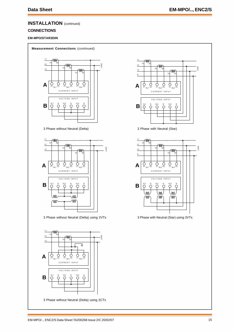
INSTALLATION (continued)
CONNECTIONS
EM-MPO/STAR3DIN
P1 P2AL1 P1 P2AL2 P1 P2AL3
VL1 N
C U R R E N T I N P U T
V O L T A G E I N P U T
N NVL2 VL3
L1
L2
LOA
D
S1 S2
L3S1 S2
S1 S2
P1 P2AL1 P1 P2AL2 P1 P2AL3
VL1 N
C U R R E N T I N P U T
V O L T A G E I N P U T
N NVL2 VL3
L1
L2
LOA
D
S1 S2
L3S1 S2
S1 S2N
3 Phase without Neutral (Delta) 3 Phase with Neutral (Star)
Measurement Connections (continued)
P1 P2AL1 P1 P2AL2 P1 P2AL3
VL1 N
C U R R E N T I N P U T
V O L T A G E I N P U T
N NVL2 VL3
L1
L2
LOA
D
S1 S2
L3S1 S2
S1 S2
P1 P2AL1 P1 P2AL2 P1 P2AL3
VL1 N
C U R R E N T I N P U T
V O L T A G E I N P U T
N NVL2 VL3
L1
L2
LOA
D
S1 S2
L3S1 S2
S1 S2N
3 Phase without Neutral (Delta) using 2VTs 3 Phase with Neutral (Star) using 3VTs
P1 P2AL1 P1 P2AL2 P1 P2AL3
VL1 N
C U R R E N T I N P U T
V O L T A G E I N P U T
N NVL2 VL3
L1
L2
LOA
D
S1 S2
L3S1 S2
3 Phase without Neutral (Delta) using 2CTs
A A
A A
A
B B
B B
B

16 EM-MPO/.., ENC2/S Data Sheet TA200268 Issue 2/C 20/02/07
EM-MPO/.., ENC2/S Data Sheet
INSTALLATION (continued)
CONNECTIONS
EM-MPO/STAR3
1 2 3 4 5 6 7 8 9 10
TX RX
OK
1 2
1 2 3 4 5 6 7 8 9 10 11
VOLTAGE INPUTMAX 600V~
CAT 111
!
CURRENT INPUTMAX 5A~
!
POWER SUPPLY50/60Hz 6VA
!
VL3 VL2 VL1 N AL3 AL2 AL1 COM 0 115 230V~
1 2
A B
RS485
123456
3 4 5 6
OUT1A
OUT1B
OUT2A
OUT2B
Meter Input Power Supply
Two part screw terminals maximumcable cross section 2.5 mm2
(14 AWG).230 Vac +15 % -20 %,35 to 400 Hz, 4VA Supply
115 Vac +15 % -20 %,50/60 Hz, 4VA Supply
LN
E
230 Vac
100 mA T
4VA~ 50/60HzPOWER SUPPLY!
0 230V~1159 10 11
LN
E
115 Vac
200 mA T
0 230V~115
4VA~ 50/60HzPOWER SUPPLY!
9 10 11
Measurement Connections
Single Phase with Neutral
Connection to ENC2/STwo part screw terminal, maximum cable cross section area of 2.5 mm2 (14 AWG)
ensure correct polarity3 m (9’ 10”)cable supplied
RS485
RS232/RS485 converter
bluered
2 Phase with Neutral
Two part screw terminals, maximum cable cross section 2.5 mm2 (14 AWG)
A
B
Note: ensure RS232/RS485 converter is connectedcorrect way round.
RS232 ← → RS485
ABSOLUTE MAX VOLTAGE 600V, MAX CURRENT 5A
Note that this instrument doesnot require an earth (ground)connection
Digital Outputs
AB
3OUT1A
4OUT1B
5OUT2A
6OUT2B
OUT1
OUT2
1 2 3 4
VOLTAGE
L
N LOA
D
S1 S2
5 6 7 8
CURRENT
VL3 VL2 VL1 N AL3 AL2 AL1 COM
1 2 3 4
VOLTAGE
L1
L2
LOA
D
S1 S2
5 6 7 8
CURRENT
VL3 VL2 VL1 N AL3 AL2 AL1 COM
N
S1 S2
Two part screw terminalsmaximum cable cross section2.5 mm2 (14 AWG).

17EM-MPO/.., ENC2/S Data Sheet TA200268 Issue 2/C 20/02/07
Data Sheet EM-MPO/.., ENC2/S
INSTALLATION (continued)
CONNECTIONS
EM-MPO/STAR3
3 Phase without Neutral (Delta) 3 Phase with Neutral (Star)
Measurement Connections (continued)
3 Phase without Neutral (Delta) using 2VTs 3 Phase with Neutral (Star) using 3VTs
3 Phase without Neutral (Delta) using 2CTs
1 2 3 4
VOLTAGE
L1
L2
LOA
D
S1 S2
5 6 7 8
CURRENT
VL3 VL2 VL1 N AL3 AL2 AL1 COM
L3
S1 S2
S1 S2
1 2 3 4
VOLTAGE
L1
L2
LOA
D
S1 S2
5 6 7 8
CURRENT
VL3 VL2 VL1 N AL3 AL2 AL1 COM
L3
S1 S2
S1 S2
N
1 2 3 4
VOLTAGE
L1
L2
LOA
D
S1 S2
5 6 7 8
CURRENT
VL3 VL2 VL1 N AL3 AL2 AL1 COM
L3
S1 S2
S1 S2
1 2 3 4
VOLTAGE
L1
L2
LOA
D
S1 S2
5 6 7 8
CURRENT
VL3 VL2 VL1 N AL3 AL2 AL1 COM
L3
S1 S2
S1 S2
N
1 2 3 4
VOLTAGE
L1
L2
LOA
D
5 6 7 8
CURRENT
VL3 VL2 VL1 N AL3 AL2 AL1 COM
L3
S1 S2
S1 S2
18 EM-MPO/.., ENC2/S Data Sheet TA200268 Issue 2/C 20/02/07
EM-MPO/.., ENC2/S Data Sheet
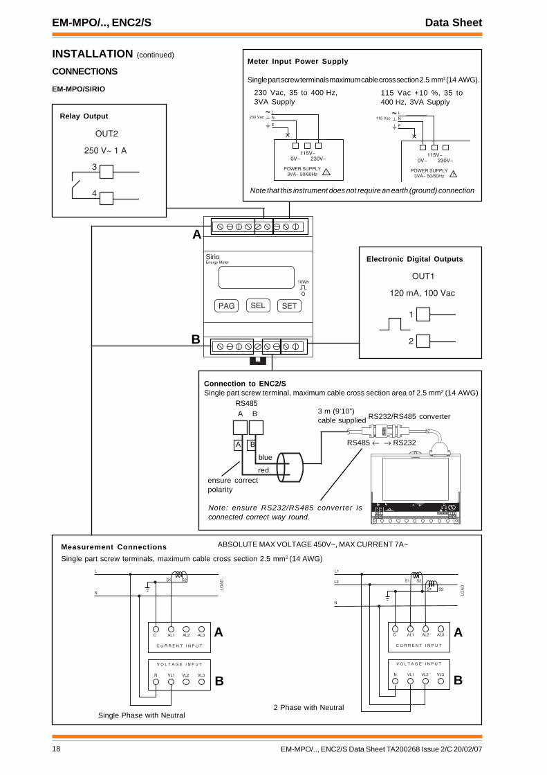
INSTALLATION (continued)
CONNECTIONS
EM-MPO/SIRIO
PAG SEL SET
SirioEnergy Meter
10Wh
Meter Input Power Supply
Single part screw terminals maximum cable cross section 2.5 mm2 (14 AWG).
230 Vac, 35 to 400 Hz,3VA Supply
115 Vac +10 %, 35 to400 Hz, 3VA Supply
LN
E
230 Vac
0V~ 230V~115V~
POWER SUPPLY3VA~ 50/60Hz !
LN
E
115 Vac
0V~ 230V~115V~
POWER SUPPLY3VA~ 50/60Hz !
Measurement Connections
Single Phase with Neutral
Connection to ENC2/SSingle part screw terminal, maximum cable cross section area of 2.5 mm2 (14 AWG)
Single part screw terminals, maximum cable cross section 2.5 mm2 (14 AWG)
ABSOLUTE MAX VOLTAGE 450V~, MAX CURRENT 7A~
Note that this instrument does not require an earth (ground) connection
Electronic Digital Outputs
C AL1 AL2 AL3
VL1N
C U R R E N T I N P U T
V O L T A G E I N P U T
VL2 VL3
L
N
LOA
DS1 S2
Relay Output
1
2
OUT1
120 mA, 100 Vac
3
4
OUT2
250 V~ 1 A
� � � � � � � � �
� � � �
� �
� �
ensure correctpolarity
3 m (9’10”)cable supplied
RS485
RS232/RS485 converter
blue
red
A B
Note: ensure RS232/RS485 converter isconnected correct way round.
RS485 ← → RS232
A B
C AL1 AL2 AL3
VL1N
C U R R E N T I N P U T
V O L T A G E I N P U T
VL2 VL3
L1
N
LOA
D
S1 S2
L2 S1 S2
2 Phase with Neutral
A
B
A
B
A
B
19EM-MPO/.., ENC2/S Data Sheet TA200268 Issue 2/C 20/02/07
Data Sheet EM-MPO/.., ENC2/S
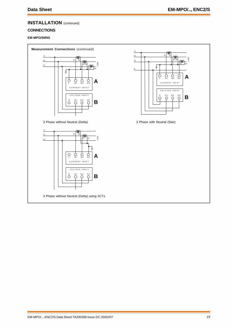
INSTALLATION (continued)
CONNECTIONS
EM-MPO/SIRIO
3 Phase without Neutral (Delta) 3 Phase with Neutral (Star)
Measurement Connections (continued)
C AL1 AL2 AL3
VL1N
C U R R E N T I N P U T
V O L T A G E I N P U T
VL2 VL3
L1
L3 LOA
D
S1 S2
L2 S1 S2
S1 S2
C AL1 AL2 AL3
VL1N
C U R R E N T I N P U T
V O L T A G E I N P U T
VL2 VL3
L1
L3 LOA
D
S1 S2
L2 S1 S2
S1 S2
N
3 Phase without Neutral (Delta) using 2CTs
C AL1 AL2 AL3
VL1N
C U R R E N T I N P U T
V O L T A G E I N P U T
VL2 VL3
L1
L3 LOA
D
L2 S1 S2
S1 S2
A
B
A
B
A
B
20 EM-MPO/.., ENC2/S Data Sheet TA200268 Issue 2/C 20/02/07
EM-MPO/.., ENC2/S Data Sheet
INSTALLATION (continued)
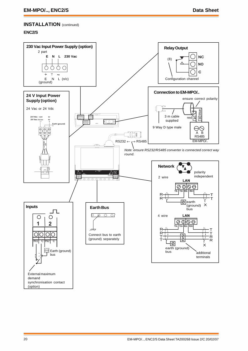
ENC2/S
� � � � � � � � �
� � � �
� �
� �
� � � � � � � � � � � �
� � � � � � � ��� � �
� � � � �
Relay Output230 Vac Input Power Supply (option)
T
T
R
R
TX-
X
TX+ RX- RX+
LAN
earth
(ground)
bus
T
T
R
R
X
T
TR
R
TX- TX+ RX- RX+
earth (ground)
bus
LAN
additionalterminals
Network
4 wire
~E N L (n/c)
2 partE N L 230 Vac
Earth Bus
Connect bus to earth(ground) separately
2 wirepolarityindependent
Inputs
Connection to EM-MPO/..
RS485A B
3 m cablesupplied
9 Way D type male
� �
IN1 C IN2 C
�
�
�
(8)
Configuration channel
ensure correct polarity
blue
red
Earth (ground)
bus
External maximumdemandsynchronisation contact(option)
24 V Input PowerSupply (option)
24 Vac or 24 Vdc
A B
RS232 ← → RS485
Note: ensure RS232/RS485 converter is connected correct wayround.
������
���
� � � � � � �
� � � � � � �
� � � � � �
� � � � � ! " � # $ % � &
' � � � � �
� �
EM-MPO/..
(ground)

21EM-MPO/.., ENC2/S Data Sheet TA200268 Issue 2/C 20/02/07
Data Sheet EM-MPO/.., ENC2/S
INSTALLATION (continued)
EM-MPO/..Mount unitConnect powerConnect current (or CTs)Connect voltage (or VTs)Connect to ENC2/SSwitch OnConfigure meter
ENC2/SMount unit in positionConnect power (do not power up)Terminate network, leave unconnectedTerminate I/O, leave unconnectedSpecify network address and baud ratePower upConnect network and checkConfigure strategyConnect I/O and checkBackup configuration
Further installation details are given as follows:EM-MPO/STAR3DIN Installation Instructions TG200770, EM-MPO/STAR3 Installation Instructions TG200771, EM-MPO/SIRIO InstallationInstructions TG200772, NBOX/ENC2/S Installation Instructions TG200270.The full configuration and use of EM-MPO/STAR3DIN is covered by EM-MPO/STAR3DIN User Manual TB200773, of EM-MPO/STAR3is covered by the EM-MPO/STAR3 User Manual TB200774, and of EM-MPO/SIRIO is covered by the EM-MPO/SIRIO User ManualTB200775.Installation of EM-MPO/STAR3DIN in a panel using the ACC/STAR3DIN/PANELKIT Panel Mounting Kit is covered byACC/STAR3DIN/PANELKIT Installation Instructions TG200338.Installation of EM-MPO/SIRIO in a panel using the ACC/SIRIO/PANELKIT Panel Mounting Kit is covered by ACC/SIRIO/PANELKITInstallation Instructions TG200775.
MAINTENANCENeither the EM-MPO/.. nor ENC2/S require any routine maintenance. From time to time the ENC2/S will require its backup battery tobe changed. This should only be undertaken by a qualified IQ system Engineer as it involves a hot-replacement method. The meterinterface script program (TCL) is lost if the battery is removed during power down. Contact your IQ system representative for advice.
DISPOSALCOSHH (Control of Substances Hazardous to Health - UKGovernment Regulations 2002) ASSESSMENT FOR DISPOSALOF NODE CONTROLLER. The only part affected is the lithiumbattery which must be disposed of in a controlled way.
RECYCLING. All plastic and metal parts are recyclable. The printed circuitboard may be sent to any PCB recovery contractor to recoversome of the components for any metals such as gold and silver.
ORDER CODESEM-MPO/STAR3DIN DIN rail mounting high quality energy analyser including installation instructions and User Manual.EM-MPO/STAR3 Front Panel Mounting energy analyser including installation instructions and User Manual.EM-MPO/SIRIO DIN rail mounting multiparameter energy meter including installation instructions and User Manual.ACC/STAR3DIN/PANELKIT Mounting kit to enable EM-MPO/STAR3DIN to be panel mounted including installation instructions.ACC/SIRIO/PANELKIT Mounting kit to enable EM-MPO/SIRIO to be panel mounted including installation instructions.NBOX/ENC2/S/230 Communications node for EM-MPO/.. meter with 230 Vac input power supply.NBOX/ENC2/S/24 Communications node for EM-MPO/.. meter with 24 Vac input power supply.
Current transformers
Current transformers (CTs) should be ordered separately. Arange of split core CTs are available from your IQ System supplieras described in the Current Transformers data sheet TA102139.
Voltage transformers
For EM-MPO/STAR3DIN and /STAR3 measuring voltages inexcess of their maximum input voltage requires voltagetransformers (VTs) to be used. They should be orderedseparately. Please note that voltage transformers are notavailable from your IQ System supplier.
WEEE Directive :
At the end of their useful life the packaging,and product should be disposed of by a suitablerecycling centre.
Do not dispose of with normal household waste.Do not burn.

22 EM-MPO/.., ENC2/S Data Sheet TA200268 Issue 2/C 20/02/07
EM-MPO/.., ENC2/S Data Sheet
SPECIFICATIONEM-MPO/STAR3DIN
Electrical
Input Power Supply Voltage :230Vac or 115 Vac, +15% -20%, 35 to 400 Hz
Meter Consumption :4VAMeter voltage :430 Vac phase to neutral, 600 Vac phase
to phase direct or greater using VTs (35to 400 Hz).
Overload voltage :850 Vac phase to neutral maximumVoltage Input Impedance :2 MΩMetered Current :External 5 A current transformer
requiredCurrent Input Consumption :1 VAMeasuring Range :0 to 120 % normal current (7 A)Overload current :withstands 50 A for 1 sSensitivity :current 20 mA, voltage 10 V.Sampling frequency :2.5 kHzMeasurements :True RMS up to 25th harmonic (1250 Hz
with 50 Hz fundamental)Measurement Accuracy :<0.5 % for V, I and PowerCT ratio selections :up to 59.9 kA:1AVT ratio selections :up to 59.9 kV:1VBackup :Maximum demand, energy meters, and
setup are protected from power fail byEeprom.
Connections :Single Phase, Diphase, 3 Phase Delta,3 Phase Star.
Communications :To ENC2/S, RS485(ASCII), 9600 Baud,no parity.
Display :LCD dot matrix.
Environmental
Safety standards :IEC1010-1 430 V for Cat 111 andprotection level 2 according to IEC664-664A regarding the safety of theoperators.
EMC :EN550011, EN61000-3-2, EN61000-3-3,EN61000-4-2, EN61000-4-3, EN6100-4-4extension 4kV, EN61000-4-5, EN61000-4-6,EN6100-4-8, EN61000-4-11
Temperature :-10 °C to +50 °C (14 °F to 122 °F)Humidity :20 % to 90 % RH non condensingProtection :instrument IP20, front panel IP40
Mechanical
Dimensions :157.5 mm x 58 mm x 90 mm (6.2” x 2.28”x 3.54”) (9 DIN modules)
Mounting :DIN rail 35 mmWeight :0.6 kg (1.32 lbs)Connectors
Measurement :V, I terminals single part screw terminalsmaximum cable cross section area 4 mm2
(12 AWG).RS485 :single part screw terminals maximum
cable cross section area 2.5 mm2
(14 AWG).
EM-MPO/STAR3
Electrical
Input Power Supply Voltage :230Vac or 115 Vac, +15% -20%, 35 to 400 Hz
Meter Consumption :4VAMeter voltage :430 Vac phase to neutral, 600 Vac phase
to phase direct or greater using VTs (35to 400 Hz).
Overload voltage :850 Vac phase to neutral maximumVoltage Input Impedance :2 MΩMetered Current :External 5 A current transformer
requiredCurrent Input Consumption :1 VAMeasuring Range :0 to 120 % normal current (5 A)Overload current :withstands 50 A for 1 sSensitivity :current 20 mA, voltage 10 V.Sampling frequency :2.5 kHzMeasurements :True RMS up to 25th harmonic (1250 Hz
with 50 Hz fundamental)Measurement Accuracy :<0.5 % for V, I and PowerCT ratio selections :up to 59.9 kA to 1AVT ratio selections :up to 59.9 kV to 1VBackup :Maximum demand, energy meters, and
setup are protected from power fail byEeprom.
Connections :Single Phase, Diphase, 3 Phase Delta, 3Phase Star.
Communications :To ENC2, RS485(ASCII), 9600 Baud, noparity.
Display :reverse red LCD with LED backlightDigital Outputs :two electronic relays, 120 mA, 250 Vac
maximum
Environmental
Safety standards :IEC1010-1 430 V for Cat 111 andprotection level 2 according to IEC664-664A regarding the safety of theoperators.
EMC :EN550011, EN61000-3-2, EN61000-3-3,EN61000-4-2, EN61000-4-3, EN6100-4-4extension 4kV, EN61000-4-5, EN61000-4-6,EN6100-4-8, EN61000-4-11
Temperature :-10 °C to +50 °C (14 °F to 122 °F)Humidity :20 % to 90 % RH non condensingProtection :instrument IP20, front panel IP40
Mechanical
Dimensions :96 mm x 96 mm x 115.4 mm (3.78” x 3.78”x 4.54”)
Mounting :front panel, cutout template 91 x 91 mm(3.58” x 3.58”)
Weight :0.6 kg (1.32 lbs)Connectors :two part screw terminals for maximum
cable cross section area 2.5 mm2
(14 AWG).

23EM-MPO/.., ENC2/S Data Sheet TA200268 Issue 2/C 20/02/07
Data Sheet EM-MPO/.., ENC2/S
SPECIFICATION (continued)
EM-MPO/SIRIO
Electrical
Input Power Supply Voltage :230Vac or 115 Vac, ±10 %, 35to 400 Hz
Meter Consumption :3VAMeter voltage :264 Vac phase to neutral, 450 Vac phase
to phase (35 to 400 Hz).Overload voltage :600 Vac phase to neutral maximumVoltage Input Impedance :2 MΩMetered Current :External 5 A current transformer
requiredCurrent Input Consumption :1 VAOverload current :maximum 7 A permanent, 15 A for 1
secondMeasurements :True RMS up to 25th harmonic (1250 Hz
with 50 Hz fundamental)Accuracy :1 % for voltage and current, 2 % for
power Class 2 IEC1036CT ratio selections :up to 59.9 kA/1AVT ratio selections :no provisions for VTsBackup :Maximum demand, energy meters, and
setup are protected from power fail byEeprom.
Connections :Single Phase, Diphase, 3 Phase Delta, 3Phase Star.
Communications :To ENC2, RS485(ASCII), 9600 Baud, noparity.
Display :8 digit LCD display (128 segment)Digital Outputs :one electronic relays, 1 mechanical
relayOUT1 :electronic relay 120 mA, 100 Vac
maximumOUT2 :mechanical relay 1 A, 250 Vac maximum
Environmental
Safety standards :IEC1010-1-400 V for Cat 111 andprotection level 2 according to IEC664-664A .
EMC :EN550081-1 ed EN55022Conforms to Directive 89/336/EEC (EMC), Directive
72/23/EEC-93/68/EEC (LVD)Temperature :-10 °C to +60 °C (14 °F to 140 °F)Humidity :20 % to 80 % RH non condensingProtection :instrument IP20, front panel IP40
Mechanical
Dimensions :70 mm x 58 mm x 90 mm (2.76” x 2.28”x 3.54”) (4 DIN modules)
Mounting :DIN rail 35 mmWeight :0.3 kg (0.66 lbs)Connectors :single part screw terminals for maximum
cable cross section area 2.5 mm2
(14 AWG).

EM-MPO/.., ENC2/S Data Sheet
24 EM-MPO/.., ENC2/S Data Sheet TA200268 Issue 2/C 20/02/07
Manufactured for and on behalf of the Environmental and Combustion Controls Division of Honeywell Technologies Sàrl, Ecublens, Routedu Bois 37,Switzerland by its Authorized Representative, Trend Control Systems Limited.
Trend Control Systems Limited reserves the right to revise this publication from time to time and make changes to the contenthereof without obligation to notify any person of such revisions or changes.
Trend Control Systems LimitedP.O. Box 34, Horsham, West Sussex, RH12 2YF, UK. Tel:+44 (0)1403 211888 Fax:+44 (0)1403 241608 www.trend-controls.comTrend Control Systems USA6670 185th Avenue NE, Redmond, Washington 98052, USA. Tel: (425)897-3900, Fax: (425)869-8445 www.trend-controls.com
SPECIFICATION (continued)
ENC2/S
Electrical
CPU :68334 32 bit micro-controller.CPU Speed :16.78 MHz.Cycle time :1 s.Memory :128 kbyte battery backed SRAM, and
256 kbyte Flash.Input Power Supply voltage
/230 :230 Vac +15%, -10%, 50 to 60 Hz./24 :24 Vac ±10%, 50 or 60 Hz or 24 Vdc
(24 V to 36 Vdc)Consumption :13 VA max.Fusing :No replaceable fuses required. All
protection self-resetting.Battery backup :Battery maintains time, and logged data
with input power supply off for at least5 years.
Battery :Saft LM2450, 3 V, or equivalent.Clock accuracy :30 s per month (typical).Network transmission :20 mA serial 2 wire current loop,
opto-isolated, polarity independentreceiver, balanced transmitter.
Network distance :Dependent on cable type, see tablebelow:
Network baud rate :Selectable by links 1k2, 4k8, 9k6, 19k2baud - set to be same as other nodes onlocal Lan.
Network address :Selectable by board switches 116nodes addressable (4 to 118, excluding9, 10). Uses selected address andselected address plus 1; both addressesmust be unique on local Lan
Inputs :Input channels 1 & 2, digital inputs. Voltfree contact. Count rate 30 Hz. Wettingcurrent = 3 mA nominal. 5 V supply.Status LED per channel (ON = closedcontact).
Relay Output :External connection 16 Configurationchannel OP8. 1 pole changeover relay.Output rated for 240 Vac single phaseonly 8 A (resistive load), 5A (inductive,cos∅ = 0.4), 30 Vdc at 5 A (resistiveload), and 20 Vdc at 5 A (inductive load).For 24 Vdc (inductive load) reduce to 2A. Arc suppression recommended, seeRelay Output Arc SuppressionInstallation Instructions, TG200208).Status LED per channel (ON = relayenergised).
selbaC duab2k1 duab6k9 duab2k91 seriwfo.oN
2819nedleBm0001
sdy0901m0001
sdy0901m007
sdy5672
7029nedleBm0001
sdy0901m0001
sdy0901m005
sdy5452
002/FH/22/1/1/PTdnerT)1178nedleB(
m0001sdy0901
m007sdy567
m053sdy083
2
002/FH/22/2/2/PTdnerT)3278nedleB(
m0001sdy0901
m005sdy545
m052sdy072
4
IndicatorsInputs :(yellow) Indicates status (ON= contact
closed)Relay output :(yellow) ON if relay energised (power) :(green) ON when input power supply is
connected (watchdog) :(red) ON if controller has a software
faultOK (network) :(green) ON if network is operating.
Flashes if prohibited controller networkaddress set (0, 2, 3, >119).
RX :(yellow) ON if current is entering thenetwork receiver
TX :(yellow) ON if current is flowing fromnetwork transmitter
Note that the (watchdog) LED flashes momentarily on power up
Mechanical
Dimensions :230 mm x 70 mm x 210 mm (9.06” x 2.76”x 8.27”) (plus RS232/RS485 converterand cables)
MaterialBox :ABSTerminal cover :Clear Styrolux
Protection :IP30Weight :1.4 kg (3.08 lbs)Connectors
/230 :2 part connector for 0.5 to 2.5 mm2 (14to 20 AWG) cross section area cable.
/24 :Mat-N-Loc 2 part connector with 3 screwterminals for 0.5 to 2.5 mm2 (14 to 20AWG) cross section area cable.
Network :2 part connector with 4 screw terminalsfor 0.5 to 2.5 mm2 (14 to 20 AWG) crosssection area cable.
I/O :2 part connector with 2 screw terminalsfor 0.5 to 2.5 mm2 (14 to 20 AWG) crosssection area cable.
EM-MPO/.. :RS232/RS485 converter connected toENC2/S by 25 Way D type female to 9 WayD type male 40 mm (1.57”) cable (supplied).RS232/RS485 converter connected toEM-MPO/.. by 9 Way D type male to strippedends 2 core 3 m (9’ 10”) cable (supplied).The stripped ends are to be screwed intothe terminals.
Environmental
EMCEmissions :EN50081-1.Immunity :EN50082-2.
Safety :EN61010.Ambient limits
storage :-10 °C to 50 °C (14 °F to 122 °F)operating :0 °C to 45 °C (32 °F to 113 °F)humidity :0 to 90 %RH non-condensing
FlammabilityCasing material :Flame retardance, UL99V0
Glow wire test, UL746A(3)Version
ENC2/S :TCL: v1.52, Strategy: ENC2v1.52f3:firmware (IQ22x) v3.1:RS232/RS485 converter K2-ADE