data sheet liquid level sensor type aks...
TRANSCRIPT

AKS 4100/4100U - Coaxial VersionAKS 4100/4100U - Cable VersionThe AKS 4100/4100U liquid level sensor is designed specifically to measure liquid levels in a wide range of refrigeration applications.
The AKS 4100/4100U liquid level sensor is based on a proven techhology called Time Domain Reflectometry (TDR) or Guided Micro Wave.
AKS 4100/4100U liquid level sensor can be used to measure the liquid level of many different refrigerants in vessels, accumulators, receivers, standpipes, etc.
The electrical output is a 2-wired, loop powered 4 – 20 mA output signal, which is proportional to the refrigerant liquid level.
AKS 4100/4100U in a cable version is suitable for HCFC, Non flammable HFC and R717 (Ammonia), and differing lengths from 800 mm / 31.5 in. and up to 5000 mm / 197 in..
The coaxial version of AKS 4100/4100U is designed for use with R744 (CO2), HCFC, Non flammable HFC and R717 (Ammonia).
The AKS 4100/4100U coaxial version should always be used for marine applications for all refrigerant types.
The AKS 4100/4100U cable version should NOT be used for CO2 or marine applications.
Dust, foam, vapour, agitated surfaces, boiling surfaces, changes in density or in the dielectric constant , εr, for the liquid have no influence on the AKS 4100/4100U performance.
Oil accumulated in the bottom of a standpipe will not disturb the liquid level signal and it is not necessary to remove AKS 4100/4100U for cleaning after oil has been drained out of the standpipe.
Features • Approved and qualified by Danfoss for refrigeration applications
• One product covering several probe lengths (cable version)
• A single product for all commonly used refrigerants (cable version)
• Cable version requires less top-end clearance for installation and service
• Proven operation with all refrigerants in combination with oil.
• No need to clean cable version when fully covered by oil.
• The cable version is very compact and easy to handle, ship, install and use with different lengths and refrigerants
• Changes of the liquid dielectric constant (εr) do not affect operation.
• 5000 mm / 197 in. probe length with cable version
• 2-wire loop powered; no separate transformer needed. Please Note: AKS 4100/4100U can be connected directly to Danfoss EKE 347 liquid level controller and thus be powered from EKE 347. If used together with Danfoss EKC 347 liquid level controller, a 14 – 30 V DC supply is required.
• Multi language HMI. Level and setting readout in mm,cm,m (ft, in.) Language HMI versions: - English (default), German, French, Spanish - English (default),Japanese, Chinese Russian
For further details regarding mechanical and electrical installation please refer to the product installation guides DKRCI.PI.SC0.D (CABLE version), DKRCI.PI.SC0.E (COAXIAL D14 version) and DKRCI.PI.SC0.H1/DKRCI.PI.SC0.J1 (COAXIAL D22 version).
Data sheet
Liquid Level Sensor Type AKS 4100/4100U
DKRCI.PD.SC0.F1.02 | 520H5687 | 1© Danfoss | DCS (MWA) | 2017.09

Contents Page
Features . . . . . . . . . . . . . . . . . . . . . . . . . . . . . . . . . . . . . . . . . . . . . . . . . . . . . . . . . . . . . . . . . . . . . . . . . . . . . . . . . . . . . . . . . . . .1
Product concept . . . . . . . . . . . . . . . . . . . . . . . . . . . . . . . . . . . . . . . . . . . . . . . . . . . . . . . . . . . . . . . . . . . . . . . . . . . . . . . . . . . .3
CABLE version . . . . . . . . . . . . . . . . . . . . . . . . . . . . . . . . . . . . . . . . . . . . . . . . . . . . . . . . . . . . . . . . . . . . . . . . . . . . . . . . . .3
COAXIAL D14 version . . . . . . . . . . . . . . . . . . . . . . . . . . . . . . . . . . . . . . . . . . . . . . . . . . . . . . . . . . . . . . . . . . . . . . . . . . .3
COAXIAL D22 version . . . . . . . . . . . . . . . . . . . . . . . . . . . . . . . . . . . . . . . . . . . . . . . . . . . . . . . . . . . . . . . . . . . . . . . . . . .3
Optional HMI . . . . . . . . . . . . . . . . . . . . . . . . . . . . . . . . . . . . . . . . . . . . . . . . . . . . . . . . . . . . . . . . . . . . . . . . . . . . . . . . . . . . . . .5
Measuring principle . . . . . . . . . . . . . . . . . . . . . . . . . . . . . . . . . . . . . . . . . . . . . . . . . . . . . . . . . . . . . . . . . . . . . . . . . . . . . . . .6
Main technical data . . . . . . . . . . . . . . . . . . . . . . . . . . . . . . . . . . . . . . . . . . . . . . . . . . . . . . . . . . . . . . . . . . . . . . . . . . . . . . . . .6
Measuring range of AKS 4100/4100U:
CABLE version . . . . . . . . . . . . . . . . . . . . . . . . . . . . . . . . . . . . . . . . . . . . . . . . . . . . . . . . . . . . . . . . . . . . . . . . . . . . . . . . . .7
COAXIAL D14 version . . . . . . . . . . . . . . . . . . . . . . . . . . . . . . . . . . . . . . . . . . . . . . . . . . . . . . . . . . . . . . . . . . . . . . . . . . .8
COAXIAL D22 version . . . . . . . . . . . . . . . . . . . . . . . . . . . . . . . . . . . . . . . . . . . . . . . . . . . . . . . . . . . . . . . . . . . . . . . . . . .8
Ordering AKS 4100/4100U . . . . . . . . . . . . . . . . . . . . . . . . . . . . . . . . . . . . . . . . . . . . . . . . . . . . . . . . . . . . . . . . . . . . . . . . . .9
Dimensions and weights . . . . . . . . . . . . . . . . . . . . . . . . . . . . . . . . . . . . . . . . . . . . . . . . . . . . . . . . . . . . . . . . . . . . . . . . . . 10
Technical data . . . . . . . . . . . . . . . . . . . . . . . . . . . . . . . . . . . . . . . . . . . . . . . . . . . . . . . . . . . . . . . . . . . . . . . . . . . . . . . . . . . . 11
Quick setup:
CABLE version . . . . . . . . . . . . . . . . . . . . . . . . . . . . . . . . . . . . . . . . . . . . . . . . . . . . . . . . . . . . . . . . . . . . . . . . . . . . . . . . 13
COAXIAL version . . . . . . . . . . . . . . . . . . . . . . . . . . . . . . . . . . . . . . . . . . . . . . . . . . . . . . . . . . . . . . . . . . . . . . . . . . . . . . 14
Forcing mA output . . . . . . . . . . . . . . . . . . . . . . . . . . . . . . . . . . . . . . . . . . . . . . . . . . . . . . . . . . . . . . . . . . . . . . . . . . . . . . . 16
Entering refrigerant dielectric gas constant. . . . . . . . . . . . . . . . . . . . . . . . . . . . . . . . . . . . . . . . . . . . . . . . . . . . . . . . 16
Saturated vapour dielectric constant . . . . . . . . . . . . . . . . . . . . . . . . . . . . . . . . . . . . . . . . . . . . . . . . . . . . . . . . . . . . . . 17
How to change the language setting (Default: English). . . . . . . . . . . . . . . . . . . . . . . . . . . . . . . . . . . . . . . . . . . . . 18
Reset to factory setting . . . . . . . . . . . . . . . . . . . . . . . . . . . . . . . . . . . . . . . . . . . . . . . . . . . . . . . . . . . . . . . . . . . . . . . . . . . 18
Data sheet | Liquid Level Sensor, type AKS 4100/4100U
DKRCI.PD.SC0.F1.02 | 520H5687 | 2© Danfoss | DCS (MWA) | 2017.09

Product concept
Cable versionThe cable version consists of: Signal converter, which can be supplied with or without HMI Mechanical process connection with 5 m / 197 in., Ø2 mm / 0.08 in. stainless cable Counterweight Accessory bag comprising: 3 mm set screws Red cover to protect mechanical process connection prior to mounting signal converter. Setting label.
With the cable version it is possible to adapt the AKS 4100/4100U to any possible length in the range of 800 mm / 31.5 in. to 5000 mm / 196.9 in.
Cable version can be used in R717 / NH3, HCFC and HFC (εr, liquid > 5.6).
CABLE version: COAXIAL D14 version:
AKS 4100/4100U is available in two different versions:
Cable versionCoaxial version
Cable version
Both Cable and Coaxial versions are available with two different mechanical process connections:
AKS 4100: G1 in. pipe thread. Aluminium gasket includedAKS 4100U: ¾ in. NPT
AKS 4100/4100U cable version must ALWAYS be installed in a standpipe.
COAXIAL D22 version:
D22 marking
Data sheet | Liquid Level Sensor, type AKS 4100/4100U
DKRCI.PD.SC0.F1.02 | 520H5687 | 3© Danfoss | DCS (MWA) | 2017.09
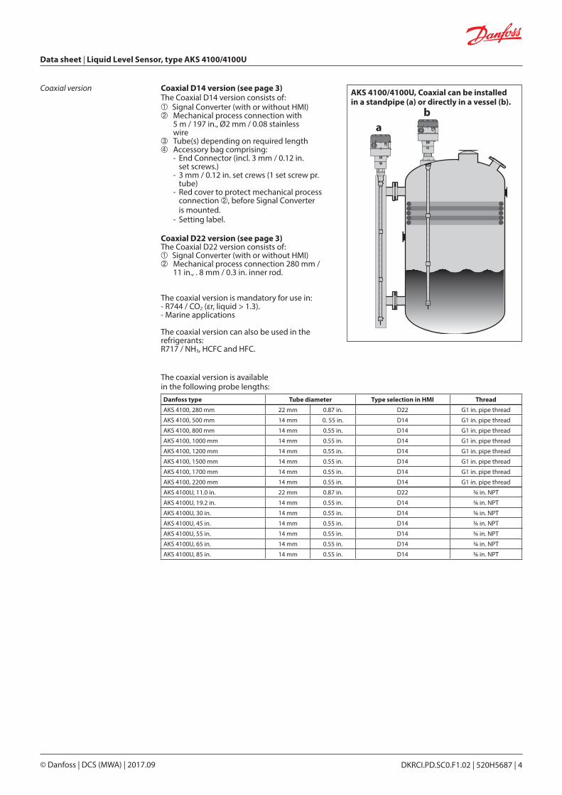
Coaxial D14 version (see page 3)The Coaxial D14 version consists of: Signal Converter (with or without HMI) Mechanical process connection with 5 m / 197 in., Ø2 mm / 0.08 stainless wire Tube(s) depending on required length Accessory bag comprising: - End Connector (incl. 3 mm / 0.12 in. set screws.) - 3 mm / 0.12 in. set crews (1 set screw pr. tube) - Red cover to protect mechanical process connection , before Signal Converter is mounted. - Setting label.
Coaxial D22 version (see page 3)The Coaxial D22 version consists of: Signal Converter (with or without HMI) Mechanical process connection 280 mm / 11 in., . 8 mm / 0.3 in. inner rod.
The coaxial version is mandatory for use in:- R744 / CO2 (εr, liquid > 1.3).- Marine applications
The coaxial version can also be used in the refrigerants:R717 / NH3, HCFC and HFC.
The coaxial version is available in the following probe lengths:
Coaxial version AKS 4100/4100U, Coaxial can be installed in a standpipe (a) or directly in a vessel (b).
ab
Danfoss type Tube diameter Type selection in HMI Thread
AKS 4100, 280 mm 22 mm 0.87 in. D22 G1 in. pipe thread
AKS 4100, 500 mm 14 mm 0. 55 in. D14 G1 in. pipe thread
AKS 4100, 800 mm 14 mm 0.55 in. D14 G1 in. pipe thread
AKS 4100, 1000 mm 14 mm 0.55 in. D14 G1 in. pipe thread
AKS 4100, 1200 mm 14 mm 0.55 in. D14 G1 in. pipe thread
AKS 4100, 1500 mm 14 mm 0.55 in. D14 G1 in. pipe thread
AKS 4100, 1700 mm 14 mm 0.55 in. D14 G1 in. pipe thread
AKS 4100, 2200 mm 14 mm 0.55 in. D14 G1 in. pipe thread
AKS 4100U, 11.0 in. 22 mm 0.87 in. D22 ¾ in. NPT
AKS 4100U, 19.2 in. 14 mm 0.55 in. D14 ¾ in. NPT
AKS 4100U, 30 in. 14 mm 0.55 in. D14 ¾ in. NPT
AKS 4100U, 45 in. 14 mm 0.55 in. D14 ¾ in. NPT
AKS 4100U, 55 in. 14 mm 0.55 in. D14 ¾ in. NPT
AKS 4100U, 65 in. 14 mm 0.55 in. D14 ¾ in. NPT
AKS 4100U, 85 in. 14 mm 0.55 in. D14 ¾ in. NPT
Data sheet | Liquid Level Sensor, type AKS 4100/4100U
DKRCI.PD.SC0.F1.02 | 520H5687 | 4© Danfoss | DCS (MWA) | 2017.09
Optional HMI
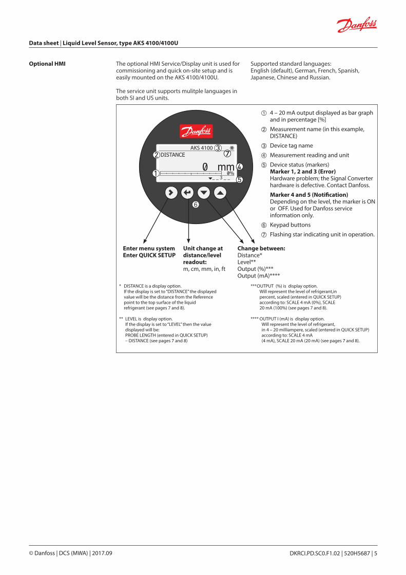
4 – 20 mA output displayed as bar graph and in percentage [%]
Measurement name (in this example, DISTANCE)
Device tag name
Measurement reading and unit
Device status (markers) Marker 1, 2 and 3 (Error) Hardware problem; the Signal Converter hardware is defective. Contact Danfoss.
Marker 4 and 5 (Notification) Depending on the level, the marker is ON or OFF. Used for Danfoss service information only.
Keypad buttons
Flashing star indicating unit in operation.
Enter menu systemEnter QUICK SETUP
Unit change atdistance/level readout:m, cm, mm, in, ft
Change between:Distance*Level**Output (%)***Output (mA)****
*AKS 4100
The optional HMI Service/Display unit is used for commissioning and quick on-site setup and is easily mounted on the AKS 4100/4100U.
The service unit supports mulitple languages in both SI and US units.
Supported standard languages:English (default), German, French, Spanish, Japanese, Chinese and Russian.
* DISTANCE is a display option. If the display is set to “DISTANCE” the displayed value will be the distance from the Reference point to the top surface of the liquid refrigerant (see pages 7 and 8).
** LEVEL is display option. If the display is set to “LEVEL” then the value displayed will be: PROBE LENGTH (entered in QUICK SETUP) – DISTANCE (see pages 7 and 8)
*** OUTPUT (%) is display option. Will represent the level of refrigerant,in percent, scaled (entered in QUICK SETUP) according to: SCALE 4 mA (0%), SCALE 20 mA (100%) (see pages 7 and 8).
**** OUTPUT I (mA) is display option. Will represent the level of refrigerant,
in 4 – 20 milliampere, scaled (entered in QUICK SETUP) according to: SCALE 4 mA (4 mA), SCALE 20 mA (20 mA) (see pages 7 and 8).
Data sheet | Liquid Level Sensor, type AKS 4100/4100U
DKRCI.PD.SC0.F1.02 | 520H5687 | 5© Danfoss | DCS (MWA) | 2017.09

Measuring principle (Cable and Coaxial)
The AKS 4100/4100U electronic converter emits low-intensity, high frequency electromagnetic pulses with a width of approximately 1 nanosecond, which travel at the speed of light along the probe (wire or coaxial cable) down to the liquid surface.
The pulses are reflected by the liquid surface, guided back along the probe, and received and analysed by the AKS 4100/4100U electronic converter and then converted into a liquid level reading. This method is called time domain reflectometry (TDR) or guided microwave.
The dielectric constant, εr, of the liquid is a key parameter and has a direct impact on the degree of reflection of the high frequency electromagnetic pulses. Liquids with high εr values, such as ammonia, produce strong reflections, while liquids with low εr values, such as CO2, produce weak reflections.
As long as the εr value of the liquid refrigerant is higher than 1.2, AKS 4100/4100U can detect the liquid level and level measurement accuracy is not affected.
If the temperature condition in the standpipe /vessel is known, a constant (dielectric constant of the refrigerant gas) can be entered (parameter 2.5.3 GAS EPS.R), in order to obtain improved Top and Bottom Dead Zone values.
Refer to pages 7 to 8 for Measuring range of AKS 4100/4100U - CABLE version and COAXIAL version.
For details of gas constant values for different temperatures and refrigerants plus the procedure for entering these via the HMI, refer to pages 16 to 17.
Main technical data(see a complete list of alltechnical data on page 11)
Supply Voltage14 – 30 V DC. Min/Max. Value for an output of 22 mA at the terminal.
Ambient temperature supply voltage limitations:-40 – 80 °C / -40 – 176 °F : 16 – 30 V DC-20 – 80 °C / -4 – 176 °F : 14 – 30 V DC
LoadRL [Ω] ≤ ((Uext -14 V) / 20 mA). – Default (Error output set to 3.6 mA)RL [Ω] ≤ ((Uext -14 V) / 22 mA). – (Error output set to 22 mA)
Cable glandAKS 4100 PG 13, M20×1.5 ; (cable diameter: 6 – 8 mm / 0.24 – 0.31in.AKS 4100U ½ in. NPT
Refrigerant temperature-60 – 100 °C / -76 – 212 °F
Ambient temperature-40 – 80 °C / -40 – 176 °F For HMI : -20 – 60 °C / -4 – 140 °F
Process pressure-1 – 100 barg / -14.5 – 1450 psig
Terminals (spring loaded) 0.5 – 1.5 mm² (~20-15 AWG)
Enclosure:IP 66/67 (~NEMA type 4X)
Mechanical connection Cable version / Coaxial version:AKS 4100: G1 in. pipe thread. Aluminium gasket includedAKS 4100U: ¾ in. NPT
Refrigerants 1)The listed refrigerants are qualified and approved by DanfossR717 / NH3 -40 – 50 °C / -40 – 122 °FR744 / CO2 -50 – 15 °C / -58 – 59 °F
HCFC: R22 -50 – 48 °C / -58 – 118 °F HFC: R404A -50 – 15 °C / -58 – 59 °F R410A -50 – 15 °C / -58 – 59 °F R134A -40 – 50 °C / -40 – 122 °F
The listed refrigerants may be used in the complete temperature range of AKS 4100/4100U, however, the accuracy may be affected if the above listed temperature range is exceeded.
Other refrigerants within the groups of HCFC and HFC can be detected and measured if the following conditions are fulfilled:
Reference conditionsDielectric constantCable version can be used in R717 / NH3, HCFC and HFC (εr, liquid > 5.6 ).
The coaxial version is mandatory for use in:- R744 / CO2 (εr, liquid > 1.3).- Marine applications.
The coaxial version can also be used in the refrigerants:R717 / NH3, HCFC and HFC.
1. The electromagnetic (EM) pulse is transmitted by the signal converter2. The pulse goes down the probe at the speed of light in air, V13. The pulse is reflected4. The pulse goes up the probe at speed, V15. The converter receives the pulse and records the signal6. The EM pulse moves at speed, V17. Transmitted EM pulse8. Half of this time is equivalent to the distance from the reference point of the device (the flange facing) to the surface of the product9. Received EM pulse
1) AKS 4100 Coaxial 280mm and AKS 4100U Coaxial 11 in are only released for R717/NH3
Data sheet | Liquid Level Sensor, type AKS 4100/4100U
DKRCI.PD.SC0.F1.02 | 520H5687 | 6© Danfoss | DCS (MWA) | 2017.09

Measuring range of AKS 4100/4100U - CABLE version
Top dead zones120 mm / 4.7 in.
Mea
surin
g ra
nge
Bottom dead zone (see tables)Counterweight: 33 mm / 1.3 in.
Min: 20 mm / 0.8 in.
Steel wire insertion length: 12 mm / 0.5 in.
Prob
e le
ngth
*
4 m
A (0
%)*
Inne
r len
gth
of th
e st
andp
ipe
DanfossM84H0017_1
20 mA (100 %)*
Reference point
Dis
tanc
e
Surface level
Stan
dpip
edi
amet
er: 2
– 4
in.
* Values to be entered into HMI Quick Setup menu and recorded on the setting label. Stick the setting label onto the Signal Converter either inside or outside.
Bottom deadzone values based on the factory setting of dielectric constant
Refrigerant Probe length range Bottom dead zone
[mm] [in.] [mm] [in.]
Ammonia,HFC, HCFC
800 31.5 115 4.2
801 – 999 31.5 – 39 120 4.7
1000 – 1999 39 – 79 150 5.9
2000 – 2999 79 – 118 180 7.1
3000 – 3999 118 – 157 210 8.3
4000 – 5000 157 – 197 240 9.4
Improved Bottom dead zone values after the adjustment of dielectric constant
Refrigerant Probe length range Bottom dead zone
[mm] [in.] [mm] [in.]
Ammonia,HFC, HCFC 800 – 5000 31.5 – 197 90 3.5
Data sheet | Liquid Level Sensor, type AKS 4100/4100U
DKRCI.PD.SC0.F1.02 | 520H5687 | 7© Danfoss | DCS (MWA) | 2017.09

Measuring range of AKS 4100/4100U - COAXIAL D14 version
Top dead zone120 mm /4.7 in.
Mea
surin
g ra
nge
Bottom dead zone(see tables) Min: 30 mm / 1.2 in.
Ø2 mm / 0.08 in.stainless wire
Prob
e le
ngth
*
4 m
A (0
%)*
Inne
r len
gth
of th
e st
and
pipe
DanfossM84H0026_1
20 mA (100 %)*
Reference point
Dis
tanc
e
Surface level
Please note: It is mandatory to input dielectric constant for CO2 applications.
* Values to be entered into HMI Quick Setup menu and recorded on the setting label. Stick the setting label onto the Signal Converter either inside or outside.
AKS 4100Dielectric Constant εr always set during Quick Setup
Refrigerant Probe Length
Bottom Dead Zone
Bottom Dead Zone
[mm] [in.] [mm] [in.]
CO2
500 19.7
170 6.7
800 31.51000 39.41200 47.21500 59.11700 66.92200 86.6
Factory setting
Refrigerant Probe Length
Bottom Dead Zone
Bottom Dead Zone
[mm] [in.] [mm] [in.]
Ammonia
500 19.7 95 3.7800 31.5 104 4.1
1000 39.4 110 4.31200 47.2 116 4.61500 59.1 125 4.91700 66.9 131 5.22200 86.6 146 5.8
Improved Bottom dead zone valuesafter the adjustment of dielectric constant
Refrigerant Probe Length
Bottom Dead Zone
Bottom Dead Zone
[mm] [in.] [mm] [in.]
Ammonia
500 19.7
80 3.2
800 31.51000 39.41200 47.21500 59.11700 66.92200 86.6
Factory setting
Refrigerant Probe Length
Bottom Dead Zone
Bottom Dead Zone
[mm] [in.] [mm] [in.]
HCFC,HFC
500 19.7 115 4.5800 31.5 124 4.9
1000 39.4 130 5.11200 47.2 136 5.41500 59.1 145 5.71700 66.9 151 5.92200 86.6 166 6.5
Improved Bottom dead zone valuesafter the adjustment of dielectric constant
Refrigerant Probe Length
Bottom Dead Zone
Bottom Dead Zone
[mm] [in.] [mm] [in.]
HCFC,HFC
500 19.7
100 3.9
800 31.51000 39.41200 47.21500 59.11700 66.92200 86.6
AKS 4100UDielectric Constant εr always set during Quick Setup
Refrigerant Probe Length
Bottom Dead Zone
Bottom Dead Zone
[in.] [in.] [mm]
CO2
19.2
6.7 170
3045556585
Factory setting
Refrigerant Probe Length
Bottom Dead Zone
Bottom Dead Zone
[in.] [in.] [mm]
Ammonia
19.2 3.73 9530 4.05 10345 4.50 11455 4.80 12265 5.10 13085 5.70 145
Improved Bottom dead zone valuesafter the adjustment of dielectric constant
Refrigerant Probe Length
Bottom Dead Zone
Bottom Dead Zone
[in.] [in.] [mm]
Ammonia
19.2
3.1 80
3045556585
Factory setting
Refrigerant Probe Length
Bottom Dead Zone
Bottom Dead Zone
[in.] [in.] [mm]
HCFC,HFC
19.2 4.52 11530 4.84 12345 5.29 13455 5.59 14265 5.89 15085 6.49 165
Improved Bottom dead zone valuesafter the adjustment of dielectric constant
Refrigerant Probe Length
Bottom Dead Zone
Bottom Dead Zone
[in.] [in.] [mm]
HCFC,HFC
19.2
3.94 100
3045556585
Mea
surin
g ra
nge
4 m
A (0
%)*
Top dead zone60 mm / 2.4 in.
Bottom dead zone(see tables)
20 mA (100 %)*
Prob
e le
ngth
*
Reference point
Dis
tanc
e
Surface level
Inne
r len
gth
of th
e st
and
pipe
Min: 30 mm / 1.2 in.
AKS 4100Factory setting
Refrigerant Probe Length
Bottom Dead Zone
Bottom Dead Zone
[mm] [in.] [mm] [in.]Ammonia 280 11.0 48 1.9
Improved Bottom dead zone valuesafter the adjustment of dielectric constant
Refrigerant Probe Length
Bottom Dead Zone
Bottom Dead Zone
[mm] [in.] [mm] [in.]Ammonia 280 11.0 40 1.6
AKS 4100UFactory setting
Refrigerant Probe Length
Bottom Dead Zone
Bottom Dead Zone
[in.] [in.] [mm]Ammonia 11.0 1.9 48
Improved Bottom dead zone valuesafter the adjustment of dielectric constant
Refrigerant Probe Length
Bottom Dead Zone
Bottom Dead Zone
[in.] [in.] [mm]Ammonia 11.0 1.6 40
Measuring range of AKS 4100/4100U - COAXIAL D22 version
* Values to be entered into HMI Quick Setup menu and recorded on the setting label. Stick the setting label onto the Signal Converter either inside or outside.
Data sheet | Liquid Level Sensor, type AKS 4100/4100U
DKRCI.PD.SC0.F1.02 | 520H5687 | 8© Danfoss | DCS (MWA) | 2017.09

Ordering AKS 4100/4100U Cable version - AKS 4100/4100U
Description Code numberwith HMI
English (default)German French
Spanish
Code numberwith HMI
English (default)JapaneseChineseRussian
Code numberwithout HMI
AKS 4100 with 5 m / 197 in., Ø2 mm / Ø0.08 in. stainless cable and counterweight 084H4501 084H4550 084H4500
AKS 4100U with 5 m / 197 in., Ø2 mm / Ø0.08 in. stainless cable and counterweight 084H4521 084H4571 084H4520
Description Probe length Code numberwith HMI
English (default)German French
Spanish
Code numberwith HMI
English (default)JapaneseChineseRussian
Code numberWithout HMI*mm in.
AKS 4100 - Coaxial D14 500 084H4510 084H4560 084H4503
AKS 4100 - Coaxial D14 800 084H4511 084H4561 084H4504
AKS 4100 - Coaxial D14 1000 084H4512 084H4562 084H4505
AKS 4100 - Coaxial D14 1200 084H4513 084H4563 084H4506
AKS 4100 - Coaxial D14 1500 084H4514 084H4564 084H4507
AKS 4100 - Coaxial D14 1700 084H4515 084H4565 084H4508
AKS 4100 - Coaxial D14 2200 084H4516 084H4566 084H4509
AKS 4100 - Coaxial D22 1) 280 084H4517 084H4567 084H4518
AKS 4100U - Coaxial D14 19.2 084H4530 084H4580 084H4524
AKS 4100U - Coaxial D14 30 084H4531 084H4581 084H4525
AKS 4100U - Coaxial D14 45 084H4532 084H4582 084H4526
AKS 4100U - Coaxial D14 55 084H4533 084H4583 084H4527
AKS 4100U - Coaxial D14 65 084H4534 084H4584 084H4528
AKS 4100U - Coaxial D14 85 084H4535 084H4585 084H4529
AKS 4100U - Coaxial D22 1) 11 084H4536 084H4586 084H45371) AKS 4100 Coaxial 280mm and AKS 4100U Coaxial 11 in. are only released for R717/NH3
Coaxial version - AKS 4100/4100U (available in predefined lengths, with or without HMI)
Accessories
Description Code numberwith HMI
English (default)German French
Spanish
Code numberwith HMI
English (default)JapaneseChineseRussian
AKS 4100/4100U HMI Service/Display unit with rear cover and mounting bracket 084H4540 084H4590
AKS 4100/4100U HMI Display 084H4548 084H4598
AKS 4100/4100U Signal Converter + Metaglass with HMI, excluding cable gland 084H4555 084H4556
AKS 4100/4100U converter connecting cable (5 pcs.) 084H4557
* When ordering without HMI please observe:
Each AKS 4100/AKS 4100 must always be programmed via the HMI display unit.
The HMI display unit can be ordered separately:• 084H4540 / 084H4590
AKS 4100/4100U HMI display unit with rear cover and mounting bracket. The mounting bracket is very useful when the AKS 4100/4100U have to be programmed. The same AKS 4100/4100U HMI display unit can be used to programme more AKS 4100/4100U and both Cable and Coaxial versions.
• 084H4548 / 084H4598 AKS 4100/4100U HMI display unit (usually spare part).
D14 D22
Data sheet | Liquid Level Sensor, type AKS 4100/4100U
DKRCI.PD.SC0.F1.02 | 520H5687 | 9© Danfoss | DCS (MWA) | 2017.09

Dimensions and weights
CABLE version
Probe length
Ø10
4 m
m /
Ø4.
1 in
.
177.5 mm / 7 in. 34.2 mm /1.4 in.
Ø2
mm
/Ø
0.08
in.
Ø22
mm
/Ø
0.9
in.
Ø92
mm
/ Ø
3.6
in.
33 mm /1.3 in.
COAXIAL D14 version
Ø10
4 m
m /
Ø4.
1 in
.
177.5 mm / 7 in. 34.2 mm /1.4 in.
Probe length
Ø14
mm
/Ø
0.6
in.
Ø21
mm
/Ø
0.8
in.
Weight: approx. 2.3 kg / 5.1 lbs
Weight: approx. 3.8 kg / 8.4 lbs
Service kits
Description Content Code number
Cable and counterweight forAKS 4100/4100U - CABLE version
Cable - 5 m / 197 in., Ø2 mm / Ø0.08 in.
084H4542Crimp
Counterweight
End connector incl screws forAKS 4100/4100U - COAXIAL D14 version
End connector (incl. 3 mm / 0.12 in. set screws) 084H4549
Process connection, counterweight and 5 m / 197 in., Ø2 mm / Ø0.08 in. cable for AKS 4100 - CABLE and COAXIAL D14 version
1 in. process connection084H4545Counterweight
Process connection, counterweight and 5 m / 197 in., Ø2 mm / Ø0.08 in. cable for AKS 4100U - CABLE and COAXIAL D14 version
3⁄4 in. NPT process connection084H4546Counterweight
Description Code number
AKS 4100/4100U Coaxial tube. Tube length : 680 mm / 26.8 in. 084H4543
AKS 4100/4100U blank top cover for signal converter 084H4544
AKS 4100/4100U Aluminium gaskets (10 pcs.) for 1in. process connection 084H4547
AKS 4100 1. in. welding connection 027F1010
Process connectionAKS 4100 - Coaxial D22 - G1 in. - 280 mm 084H4551
Process connectionAKS 4100U - Coaxial D22 - ¾ in. NPT – 11 in. 084H4552
Other spare parts
Ordering AKS 4100/4100UContinued
Data sheet | Liquid Level Sensor, type AKS 4100/4100U
DKRCI.PD.SC0.F1.02 | 520H5687 | 10© Danfoss | DCS (MWA) | 2017.09

Technical data Measuring system Measuring principle 2-wire loop-powered level transmitter; Time Domain Reflectometry (TDR )
Application range Level measurement of liquid refrigerants.Approved refrigerants:
Halogen Free / Environmently friendly: R717 / NH3, R744 / CO2
HCFC and non flammable HFC.
Primary measured value Time between the emitted and received signal
Secondary measured value Distance or level
DesignOptions Probe types
CableMechanical process connection with 5 m / 197 in., Ø2 mm / 0.08 in. stainless cable:Mechanical thread on the mechanical process connectionAKS 4100: G1 in. pipe thread. Aluminium gasket includedAKS 4100U: ¾ in. NPT
Coaxial D14Mechanical process connection with 5 m / 197 in., Ø2 mm / 0.08 in. stainless cable and 14 mm / 0.55 in. outer stainless tube: Mechanical thread on the mechanical process connectionAKS 4100: G1 in. pipe thread. Aluminium gasket includedAKS 4100U: ¾ in. NPTStainless steel tubes supporting the available probe length
Coaxial D22Mechanical process connection with in 22 mm / 0.87 in. outer stainless tube. 8 mm / 0.3 in. inner rod.Mechanical thread on the mechanical process connection AKS 4100: G1 in. pipe thread. Aluminium gasket included AKS 4100U: ¾ in. NPT
LCD display
Insertions (probe) length Coaxial D14AKS 4100: 500, 800, 1000, 1200, 1500, 1700 and 2200 mmAKS 4100U: 19.2, 30, 45, 55, 65, 85 in.
Coaxial D22AKS 4100: 280 mm AKS 4100U: 11.0 in.
Single cable Ø2 mm / 0.08 in.: 800 – 5000 mm / 31.5-197 in.
Dead zone This depends on the type of probe. (see pages 7 and 8)
Display and User interfaceDisplay Integrated LCD display
128 × 64 pixels in 8-step greyscale with 4-button keypad
Interface languages English (default), German, French, Spanish, Japanese, Chinese, Russian
Operating conditionsTemperature:
Ambient temperature -40 – 80 °C / -40 – 175 °F For HMI : -20 – 60 °C / -4 – 140 °F
Storage temperature -40 – 85 °C / -40 – 185 °F
Process connection temperature Standard-60 – 100 °C / -76 – 212 °F
Pressure:
Operating pressure Standard:-1 – 100 barg / -14.5 – 1450 psig
Dimensions and weights (continued)
COAXIAL D22 version
Weight: 2.4 kg / 5.3 lbs
Ø 1
04 m
m /
Ø 4
.1 in
.
177.5 mm / 7 in.34.2 mm /
1.4 in. Probe length
21.1
mm
/0.
8 in
.
Data sheet | Liquid Level Sensor, type AKS 4100/4100U
DKRCI.PD.SC0.F1.02 | 520H5687 | 11© Danfoss | DCS (MWA) | 2017.09

Technical data(continued)
Material Housing Aluminium
Coaxial D14 and D22 version Standard: Stainless steel (1.4404 / 316L)
Single cable Standard: Stainless steel (1.4401 / 316)
Process fitting Standard: Stainless steel (1.4404 / 316L)
Gaskets EPDM (-50 – 150 °C / -58 – 300 °F)
Cable gland Plastic (black)
Process connectionsThread:
Single cable Ø2 mm / 0.08¨ AKS 4100: G1 inch pipe thread. Aluminium gasket includedAKS 4100U: ¾ in. NPT
Coaxial D14 and D22 version AKS 4100: G1 inch pipe thread. Aluminium gasket includedAKS 4100U: ¾ in. NPT
Electrical connectionsPower supply Terminals output:
14 – 30 V DC. Min./Max. Value for an output of 22 mA at the terminal.
Ambient temperature limitations:-40 – 80 °C / -40 – 176 °F : 16 – 30 V DC-20 – 80 °C /-4 – 176 °F : 14 – 30 V DC
Current output load RL [Ω] ≤ ((Uext -14 V)/20 mA). – Default (Error output set to 3.6 mA) RL [Ω] ≤ ((Uext -14 V)/22 mA). – (Error output set to 22 mA)
Cable gland AKS 4100: PG 13, M20×1.5 ; (cable diameter: 6 – 8 mm / 0.24 – 0.31 in.)AKS 4100U: ½ in. NPT
Cable entry capacity (terminal) 0.5 – 1.5 mm2 (~20-15 AWG)
Input and outputCurrent output:
Output signal 4…20 mA or 3.8…20.5 mA acc. to NAMUR NE 43
Resolution ±3 μA
Temperature drift Typically 75 ppm/K
Error signal High: 22 mA; Low: 3.6 mA acc. to NAMUR NE 43; Hold (frozen value - not available with NAMURNE 43 compliant output.
Approvals and certificationThis device fufills the statutory requirements of the EMC directives. The manufacturer certifies successful testing of the product by applying the CE mark.
Pattern Approval Certificate of Measuring Instruments for the Russian Federation
In compliance with EMC regulations in the Russian Federation
Other standards and approvals:
EMC EMC Directives 2004 / 108 / EC and 93 / 68 / EEC in conjunction withEN 61326-1 (2006) and EN 61326-2-3 (2006). The device conforms to these standards if :- the device has a coaxial probe or- the device has a single probe that is installed in a metallic tank.
LVD Low-Voltage Directives 2006 / 95 / EC and 93 / 68 / EEC in conjunction withEN 61010-1 (2001)
NAMUR NAMUR NE 21 Electromagnetic Compatibility (EMC) of Industrial Process andLaboratory Control Equipment
NAMUR NE 43 Standardization of the Signal Level for the Failure Information ofDigital Transmitters
Valid for AKS 4100 - Not valid for AKS 4100U:
Other conditions:
Liquid dielectric constant (εr) Cable version to be used in R717 / NH3, HCFC and HFC εr, liquid > 5.6 Coaxial version is mandatory in R744 / CO2 εr, liquid > 1.3
Vibration resistance EN 60721-3-4 (1...9 Hz: 3 mm / 10...200 Hz:1g; 10g shock half-wave sinusoidal: 11 ms)
Protection category IP 66/67 equivalent to NEMA type 4X (housing) and type 6P (probe)
Installation conditionsDimensions and weights See pages 10 and 11
Data sheet | Liquid Level Sensor, type AKS 4100/4100U
DKRCI.PD.SC0.F1.02 | 520H5687 | 12© Danfoss | DCS (MWA) | 2017.09

Quick Setup (all values below are only examples)
Note: The signal converter can be programmed with or without mechanical process connector assembled.
• Connect the device to the power supply (see the section "Electrical installation/ connection".
• Press 3 times.
• Press
• Press or to select between SINGLE, COAXIAL D14 and COAXIAL D22. Choose SINGLE and press to confirm.
• Press to change the PROBE LENGTH. Press to change the position of the cursor. Press to decrease the value or to increase the value. Press to confirm.
AKS 4100
QUICK SETUP ?
YES NO
AKS 4100PROBE TYPESINGLE CABLE
AKS 4100PROBE LENGTH
05000 mm
AKS 4100SCALE 4 mA
04946 mm
AKS 4100SCALE 20 mA
00070 mm
• Press to change of SCALE 4 mA. Press to change the cursor position. Press to decrease the value or to increase the value. Press to confirm.
• Press to change of SCALE 20 mA. Press to change the cursor position. Press to decrease the value or to increase the value. Press to confirm.
• Wait for QUICK SETUP to complete 8-second timeout
AKS 4100
QUICK SETUP COMPLETED IN 8
AKS 41001.0.0
QUICK START
AKS 41001.0.0
STORE NO
AKS 4100DISTANCE
5000 mm
• Press to confirm.
• Press or to select either STORE NO or STORE YES. Press to confirm.
Default screen appears:
Quick Setup completed
You have the possibility of checking your settings by pressing twice.
Press to return to default screen.
AKS 4100
QUICK SETUP ?
YES NO
AKS 4100
QUICK SETUP ?
YES NO
AKS 4100SINGLE CABLE 5000 mm(0%) 4 mA 4877 mm(100%) 20 mA 120 mm
Minimum power supply voltageUse this graph to find the minimum power supply voltage for a given current output load:
Technical data(continued)
Minimum power supply voltage for an output of 22mA at the terminal
Power supply U [VDC]
Cur
rent
out
put
load
RL
[Ω]
Data sheet | Liquid Level Sensor, type AKS 4100/4100U
DKRCI.PD.SC0.F1.02 | 520H5687 | 13© Danfoss | DCS (MWA) | 2017.09
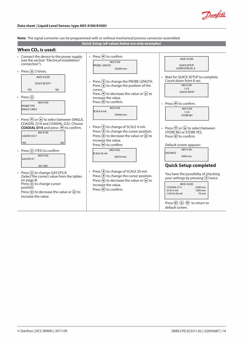
• Connect the device to the power supply (see the section "Electrical installation/ connection").
• Press 3 times.
• Press
• Press or to select between SINGLE, COAXIAL D14 and COAXIAL D22. Choose COAXIAL D14 and press to confirm.
• Press (YES) to confirm
• Press to change GAS EPS.R. (Select the correct value from the tables on page 8) Press to change cursor- position. Press to decrease the value or to increase the value.
AKS 4100
QUICK SETUP ?
YES NO
AKS 4100PROBE TYPESINGLE CABLE
• Press to confirm.
• Press to change the PROBE LENGTH. Press to change the position of the cursor. Press to decrease the value or to increase the value. Press to confirm.
• Press to change of SCALE 4 mA. Press to change the cursor position. Press to decrease the value or to increase the value. Press to confirm.
• Press to change of SCALE 20 mA. Press to change the cursor position. Press to decrease the value or to increase the value. Press to confirm.
• Wait for QUICK SETUP to complete. Count down from 8 sec.
• Press to confirm.
• Press or to select between STORE NO or STORE YES. Press to confirm.
Default screen appears:
Quick Setup completed
You have the possibility of checking your settings by pressing twice.
Press to return to default screen.
Quick Setup (all values below are only examples)
AKS 4100GAS EPS R ?
001.000
AKS 4100PROBE LENGTH
05000 mm
AKS 4100SCALE 4 mA
04946 mm
AKS 4100SCALE 20 mA
00070 mm
AKS 4100
QUICK SETUP COMPLETED IN 8
AKS 41001.0.0
QUICK START
AKS 41001.0.0
STORE NO
AKS 4100DISTANCE
5000 mm
When CO2 is used:
AKS 4100LIQUID CO2 ?
YES NO
Note: The signal converter can be programmed with or without mechanical process connector assembled.
AKS 4100
QUICK SETUP ?
YES NO
AKS 4100COAXIAL 2200 mm(0 %) 4 mA 1900 mm(100 %) 20 mA 70 mm
D14
Data sheet | Liquid Level Sensor, type AKS 4100/4100U
DKRCI.PD.SC0.F1.02 | 520H5687 | 14© Danfoss | DCS (MWA) | 2017.09

• Connect the device to the power supply (see the section "Electrical installation/ connection").
• Press 3 times.
• Press
• Press or to select between SINGLE, COAXIAL D14 and COAXIAL D22. Choose COAXIAL D14 and press to confirm.
• Press (NO) to confirm
AKS 4100
QUICK SETUP ?
YES NO
AKS 4100PROBE TYPESINGLE CABLE
• Press to change the PROBE LENGTH. Press to change the position of the cursor. Press to decrease the value or to increase the value. Press to confirm.
• Press to change of SCALE 4 mA. Press to change the cursor position. Press to decrease the value or to increase the value. Press to confirm.
• Press to change of SCALE 20 mA. Press to change the cursor position. Press to decrease the value or to increase the value. Press to confirm.
• Wait for QUICK SETUP to complete. Count down from 8 sec.
• Press to confirm.
• Press or to select between STORE NO or STORE YES. Press to confirm.
Default screen appears:
Quick Setup completed
For all other refrigerants (please note that Coaxial D22 version can only be used in R717/NH3):
AKS 4100LIQUID CO2 ?
YES NO
AKS 4100SCALE 4 mA
04946 mm
AKS 4100SCALE 20 mA
00070 mm
AKS 4100
QUICK SETUP COMPLETED IN 8
AKS 41001.0.0
STORE NO
AKS 4100DISTANCE
5000 mm
AKS 41001.0.0
QUICK START
AKS 4100PROBE LENGTH
05000 mm
AKS 4100
QUICK SETUP ?
YES NO
Data sheet | Liquid Level Sensor, type AKS 4100/4100U
DKRCI.PD.SC0.F1.02 | 520H5687 | 15© Danfoss | DCS (MWA) | 2017.09
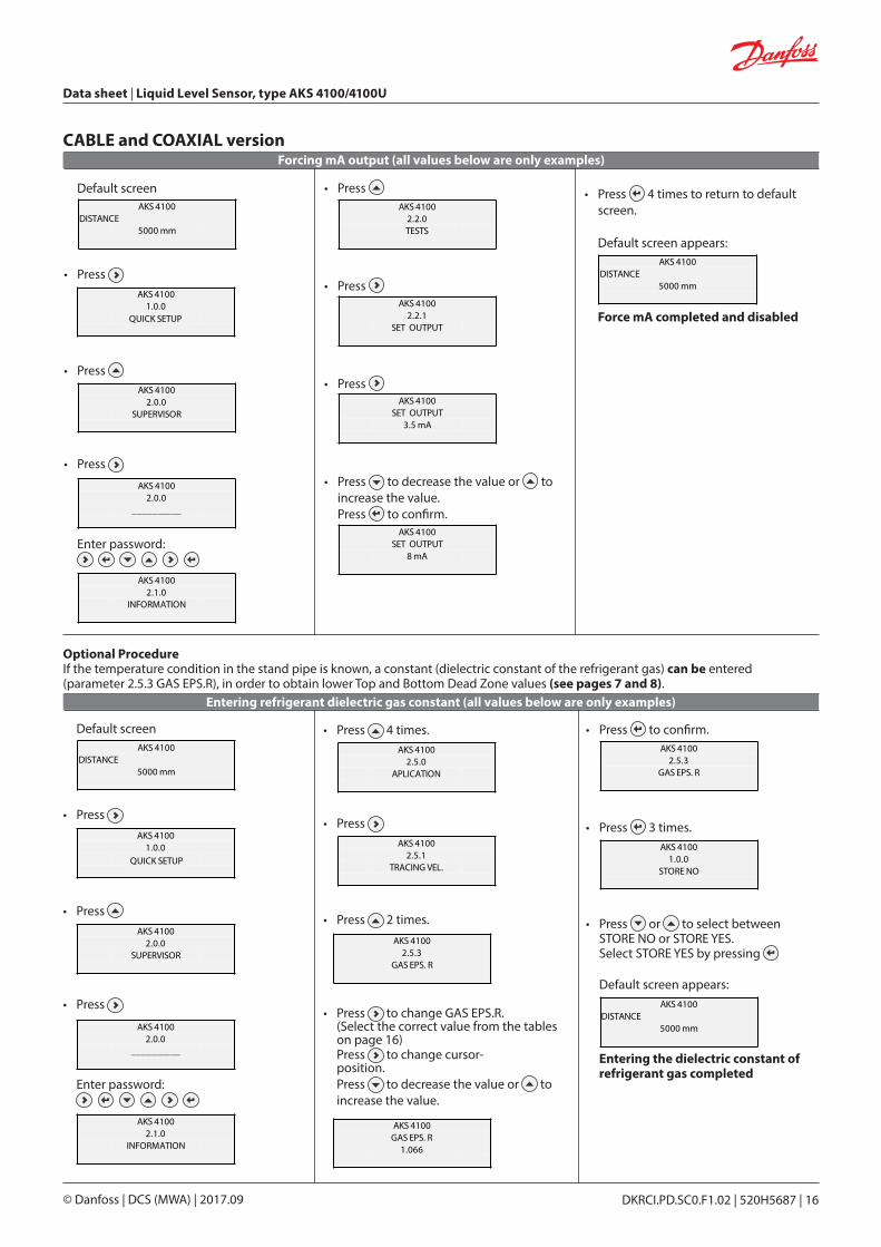
Default screen
• Press
• Press
• Press
Enter password:
AKS 4100DISTANCE
5000 mm
AKS 41001.0.0
QUICK START
AKS 41002.0.0
SUPERVISOR
AKS 41002.0.0
__________
AKS 41002.1.0
INFORMATION
AKS 41002.5.0
APLICATION
AKS 41002.5.1
TRACING VEL.
• Press 4 times.
• Press
• Press 2 times.
• Press to change GAS EPS.R. (Select the correct value from the tables on page 16) Press to change cursor- position. Press to decrease the value or to increase the value.
AKS 41002.5.3
GAS EPS. R
AKS 4100GAS EPS. R
1.066
AKS 41002.5.3
GAS EPS. R
AKS 41001.0.0
STORE NO
AKS 4100DISTANCE
5000 mm
• Press to confirm.
• Press 3 times.
• Press or to select between STORE NO or STORE YES. Select STORE YES by pressing
Default screen appears:
Entering the dielectric constant of refrigerant gas completed
Entering refrigerant dielectric gas constant (all values below are only examples)
Optional ProcedureIf the temperature condition in the stand pipe is known, a constant (dielectric constant of the refrigerant gas) can be entered (parameter 2.5.3 GAS EPS.R), in order to obtain lower Top and Bottom Dead Zone values (see pages 7 and 8).
Default screen
• Press
• Press
• Press
Enter password:
AKS 4100DISTANCE
5000 mm
AKS 41002.0.0
SUPERVISOR
AKS 41002.0.0
__________
AKS 41002.1.0
INFORMATION
AKS 41002.2.0TESTS
AKS 41002.2.1
SET OUTPUT
AKS 4100SET OUTPUT
3.5 mA
AKS 4100SET OUTPUT
8 mA
AKS 4100DISTANCE
5000 mm
• Press
• Press
• Press
• Press to decrease the value or to increase the value. Press to confirm.
• Press 4 times to return to default screen.
Default screen appears:
Force mA completed and disabled
Forcing mA output (all values below are only examples)CABLE and COAXIAL version
AKS 41001.0.0
QUICK START
AKS 4100
QUICK SETUP ?
YES NO
AKS 4100
QUICK SETUP ?
YES NO
Data sheet | Liquid Level Sensor, type AKS 4100/4100U
DKRCI.PD.SC0.F1.02 | 520H5687 | 16© Danfoss | DCS (MWA) | 2017.09
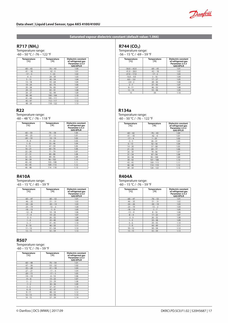
Saturated vapour dielectric constant (default value: 1.066)
R717 (NH3)Temperature range:-60 – 50 °C / -76 – 122 °F
R744 (CO2)Temperature range:-56 – 15 °C / -69 – 59 °F
R22Temperature range:-60 – 48 °C / -76 – 118 °F
R134aTemperature range:-60 – 50 °C / -76 – 122 °F
R404ATemperature range:-60 – 15 °C / -76 – 59 °F
R410ATemperature range:-65 – 15 °C / -85 – 59 °F
Temperature [°C]
Temperature [°F]
Dielectric constant of refrigerant gasParameter 2.5.3
GAS EPS.R-60 – -42 -76 – -43 1.00-41 – -18 42 – 0 1.01 -17 – -5 1 – 23 1.02 -4 – 4 24 – 39 1.035 – 12 40 – 54 1.04
13 – 18 55 – 64 1.0519 – 24 65 – 75 1.0625 – 28 76 – 82 1.0729 – 33 83 – 91 1.0834 – 37 92 – 99 1.0938 – 40 100 – 104 1.1041 – 44 105 – 111 1.1145 – 47 112 – 117 1.1248 – 50 118 – 122 1.13
Temperature [°C]
Temperature [°F]
Dielectric constant of refrigerant gasParameter 2.5.3
GAS EPS.R -56.0 – -42.0 -69 – -43 1.01 -41.0 – -28.0 -42 – -18 1.02 -27.0 – -17.0 -17 – 2 1.03 -16.0 – -9.0 3 – 16 1.04 -8.0 – -3.0 17 – 27 1.05
-2.0 – 2 28 – 36 1.063 – 7 37 – 45 1.07
8 – 11 46 – 52 1.0812 – 14 53 – 58 1.09
15 59 1.10
Temperature [°C]
Temperature [°F]
Dielectric constant of refrigerant gasParameter 2.5.3
GAS EPS.R -60 – -50 -76 – -58 1.00 -49 – -25 57 – -13 1.01 -24 – -10 -12 – 14 1.02
-9 – 0 15 – 32 1.031 – 8 33 – 46 1.04
9 – 15 47 – 59 1.0516 – 21 60 – 70 1.0622 – 26 71 – 79 1.0727 – 31 80 – 88 1.0832 – 35 89 – 95 1.0936 – 39 96 – 102 1.1040 – 42 103 – 108 1.1143 – 45 109 – 113 1.1246 – 48 114 – 118 1.13
Temperature [°C]
Temperature [°F]
Dielectric constant of refrigerant gasParameter 2.5.3
GAS EPS.R -60 – -42 -76 – -43 1.00 -41 – -18 -42 – -0 1.01 -17 – -4 1 – 25 1.02 -3 – 5 26 – 41 1.036 – 13 42 – 56 1.04
14 – 20 57 – 68 1.0521 – 25 69 – 77 1.0626 – 30 78 – 86 1.0731 – 34 87 – 94 1.0835 – 38 95 – 100 1.0939 – 42 101 – 108 1.1043 – 45 109 – 113 1.1146 – 48 114 – 119 1.1249 – 50 120 – 122 1.13
Temperature [°C]
Temperature [°F]
Dielectric constant of refrigerant gasParameter 2.5.3
GAS EPS.R -60 – -47 -76 – -52 1.01 -46 – -35 -51 – -31 1.02 -34 – -26 -30 – -14 1.03 -25 – -19 -13 – -2 1.04 -18 – -14 -1 – 7 1.05 -13 – -9 8 – 16 1.06 -8 – -4 17 – 25 1.07 -3 – 0 26 – 32 1.081 – 3 33 – 38 1.094 – 6 39 – 43 1.107 – 9 44 – 49 1.11
10 – 12 50 – 54 1.1213 – 15 55 – 59 1.13
Temperature [°C]
Temperature [°F]
Dielectric constant of refrigerant gasParameter 2.5.3
GAS EPS.R -65 – -47 -85 – -52 1.01 -46 – -35 -51 – -31 1.02 -34 – -26 -30 – -14 1.03 -25 – -19 -13 – -2 1.04 -18 – -13 -1 – 9 1.05 -12 – -8 10 – 18 1.06 -7 – -4 19 – 25 1.07 -3 – 0 26 – 32 1.081 – 4 33 – 40 1.095 – 7 41 – 45 1.10
8 – 10 46 – 50 1.1111 – 12 51 – 54 1.1213 – 15 55 – 59 1.13
Temperature [°C]
Temperature [°F]
Dielectric constant of refrigerant gasParameter 2.5.3
GAS EPS.R -60 – -48 -76 – -54 1.01 -47 – -36 -53 – -32 1.02 -35 – -28 -31 – -18 1.03 -27 – -21 -17 – -6 1.04 -20 – -15 -17 – -5 1.05 -14 – -10 -4 – 14 1.06
-9 – -6 13 – 22 1.07-5 – -2 23 – 29 1.08-1 – 2 30 – 36 1.093 – 5 37 – 41 1.106 – 8 42 – 47 1.11
9 – 11 48 – 52 1.1212 – 13 53 – 56 1.1314 – 15 57 – 59 1.14
R507Temperature range:-60 – 15 °C / -76 – 59 °F
Data sheet | Liquid Level Sensor, type AKS 4100/4100U
DKRCI.PD.SC0.F1.02 | 520H5687 | 17© Danfoss | DCS (MWA) | 2017.09

Default screen
• Press
• Press
• Press
AKS 4100DISTANCE
5000 mm
AKS 41001.0.0
QUICK START
AKS 41002.0.0
SUPERVISOR
AKS 41002.0.0
__________
AKS 41002.1.0
INFORMATION
AKS 4100DISTANCE
5000 mm
Enter password:
• Press 6 times
• Press
• Press
• Press or to see the language possibilities Press to confirm.
• Press 3 times
• Press or to select between STORE NO or STORE YES. Select STORE YES by pressing Default screen appears:
Language setup completed
How to change the language setting (Default: English)
AKS 4100
QUICK SETUP ?
YES NO
Reset to factory setting
AKS 41002.7.0
DISPLAY
AKS 41002.7.1
LANGUAGE
AKS 4100LANGUAGEENGLISH
AKS 41002.7.1
LANGUAGE
AKS 41002.0.0
STORE NO
• Go to SUPERVISOR menu (see page 16).
• Go to parameter 2.9.4 Reset Factory.• Select RESET FACTORY YES
• Press 3 times to return to default screen.
Factory reset completed.
Data sheet | Liquid Level Sensor, type AKS 4100/4100U
DKRCI.PD.SC0.F1.02 | 520H5687 | 18© Danfoss | DCS (MWA) | 2017.09

Data sheet | Liquid Level Sensor, type AKS 4100/4100U
DKRCI.PD.SC0.F1.02 | 520H5687 | 19© Danfoss | DCS (MWA) | 2017.09
DKRCI.PD.SC0.F1.02 | 520H5687 | 20© Danfoss | DCS (MWA) | 2017.09