data sheet wöhr parklift 461 462 463-2,0 - proidea · 2011-11-30 · data sheet wöhr parklift 461...
TRANSCRIPT
Data SheetWöhrParklift 461 462 463-2,0
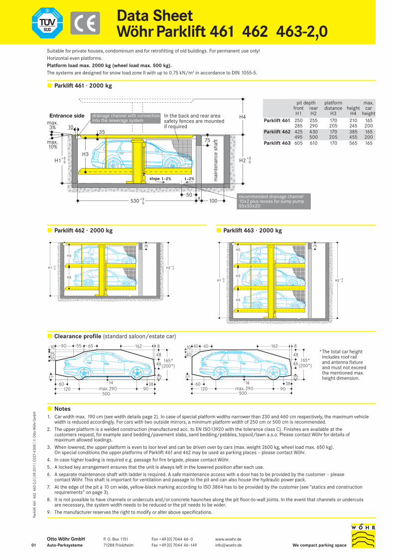
Parklift 461 · 2000 kg
Parklift 462 · 2000 kg
Clearance profile (standard saloon/estate car)
Notes1. Car width max. 190 cm (see width details page 2). In case of special platform widths narrower than 230 and 460 cm respectively, the maximum vehicle
width is reduced accordingly. For cars with two outside mirrors, a minimum platform width of 250 cm or 500 cm is recommended.2. The upper platform is a welded construction (manufactured acc. to EN ISO13920 with the tolerance class C). Finishes are available at the
customers request, for example sand bedding/pavement slabs, sand bedding/pebbles, topsoil/lawn a.s.o. Please contact Wöhr for details of maximum allowed loadings.
3. When lowered, the upper platform is even to loor level and can be driven over by cars (max. weight 2600 kg, wheel load max. 650 kg). On special conditions the upper platforms of Parklift 461 and 462 may be used as parking places – please contact Wöhr.
4. In case higher loading is required e.g. passage for fire brigade, please contact Wöhr. 5. A locked key arrangement ensures that the unit is always left in the lowered position after each use.6. A separate maintenance shaft with ladder is required. A safe maintenance access with a door has to be provided by the customer – please
contact Wöhr. This shaft is important for ventilation and passage to the pit and can also house the hydraulic power pack.7. At the edge of the pit a 10 cm wide, yellow-black marking according to ISO 3864 has to be provided by the customer (see “statics and construction
requirements“ on page 3).8. It is not possible to have channels or undercuts and/or concrete haunches along the pit floor-to-wall joints. In the event that channels or undercuts
are necessary, the system width needs to be reduced or the pit needs to be wider.9. The manufacturer reserves the right to modify or alter above specifications.
pit depth platform max.front rear distance height carH1 H2 H3 H4 height
Parklift 461 250 255 170 210 165285 290 205 245 200
Parklift 462 425 430 170 385 165495 500 205 455 200
Parklift 463 605 610 170 565 165
10
2238
2025
90 55 162
500120
275
60max.290 90
46
65 8
14
48165*(200*)
10
12060 3814
275 22
46
90max.290500
48
81626040
40165*(200*)
Suitable for private houses, condominium and for retrofitting of old buildings. For permanent use only! Horizontal even platforms. Platform load max. 2000 kg (wheel load max. 500 kg).The systems are designed for snow load zone II with up to 0.75 kN/m2 in accordance to DIN 1055-5.
Parklift 463 · 2000 kg
3510
530 x
H3
mai
nten
ance
sha
ft
Entrance side
max.3%
max.10%
75
In the back and rear areasafety fences are mountedif required
10050
H1 H2
H4
recommended drainage channel10x2 plus recess for sump pump50x50x20
drainage channel with connectioninto the sewerage system
+30
+30
+30
slope 1–2% 1–2%
75
H3
H1 H2
H3
+30
+30
75H3
H1 H2H3
H3
+30
+30
*The total car height includes roof rail and antenna fixture and must not exceed the mentioned max. height dimension.
P. O. Box 115171288 Friolzheim We compact parking space
Fon +49 [0] 7044 46-0Fax +49 [0] 7044 46-149
Park
lift 4
61 4
62 4
63-2
,0| 0
9.20
11 |
C02
7-43
08| ©
Ott
o W
öhr G
mbH
01Otto Wöhr GmbHAuto-Parksysteme

Width dimensions
Top view closed pit
Pit dimensions
Important notes
All dimensions shown are minimum. Construction tolerances must be taken into consideration. All dimensions in cm.Alle Maße in cm.The access to the Parklift is possible with max. 3% declination and max. 10% inclination.If not stated differently in the offer, platform widths of 230cm or 460cm will be delivered. Bigger/smaller platform widths can be delivered at additional price.
Attention: If sides or the back are freely accessible, a safeguard is necessary (safety fences, marking, electrical hauling cable counter, or similar). This is planned dependent on project.BeIf maximum platform widths are not installed, difficulties might arise when entering or exiting the cars on the parking units. This depends on the car type, the access and the individual driving behaviour.Cars wider than 190 cm should be parked on platforms 270/500 cm width only for entering/exiting at drivers position.
Single unit Double unit Row arrangement (Single- and Doubleunits are combinable)
(top view)
Row arrangementSingle unit(front view)
Double unit
* Measure 35 cm upon upper edge platform pavement
** The passageway to the neighbour units must have the identical height like the passageway of the maintenance shaft in the pit.
A rectangular angle is required from the sidewalls to the front side. Max. tolerances are 1 cm!
gives clear Space platform width
required parking upperB levels platform
275 230 290285 240 300295 250 310305 260 320315 270 330
drainagechannel
10
10 10
- 0,35
0,00top edgefinishedfloor
80
drainagechannel
10
10
door(provided bythe customer)
10
- 0,35
0,00top edgefinishedfloor
80
shaft formaintenance
drainagechannel
175
10
10 175 10
- 0,35partitionwalls
- 0,35
0,00top edgefinishedfloor
80
passage** 40
80
80
40
D S/D S/DS/D
B 1010
35*
20
15
15
wall opening forhydraulic conduits
75
B 1010
35* 75
20
15
15
B 1017510 175BB
35* 35*
20
15
15
75
shaft covering(provided bythe customer)
upper platform
Entrance side
S
gives clear Space platform width
required parking upperB levels platform
505 460 520525 480 540545 500 560565 520 580585 540 600
Park
lift 4
61 4
62 4
63-2
,0| 0
9.20
11 |
C02
7-43
08| ©
Ott
o W
öhr G
mbH
02
Statics and construction requirements
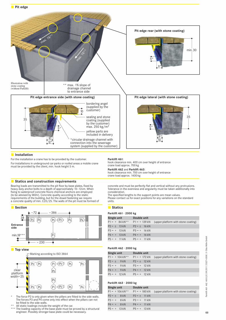
Pit edge
Section Statics
Top view
Bearing loads are transmitted to the pit floor by base plates, fixed by heavy duty anchor bolts to a depth of approximately 10–12cm. When fixing to waterproof concrete floors chemical anchors are employed (to be advised by Wöhr). Concrete quality according to the static requirements of the building, but for the dowel fastening we require a concrete quality of min. C20/25. The walls of the pit must be formed of
concrete and must be perfectly flat and vertical without any protrusions. Tolerance in the evenness and angularity must be taken additionally intoconsideration. The specified lengths to the support points are mean values. Please contact us for exact positions for any variations on the standard units.
P5
P1
P4P3 P5 P538
~ 230
~72
min.18***
Entranceside
~386
P2+ –
P5
P1 P4P3
P1 P4P3
P5
*
*
* *
*P5 P5
P5 P5
*
P2+ –
P2+ –
clearplatform
width+25
* The force P2 is only given when the pillars are fitted to the side walls. The forces P3 and P4 come only into effect when the pillars can not be fitted to the side walls.
** All static loadings include the weight of the car.*** The loading capacity of the base plate must be proved by a structural
engineer. Possibly stronger base plate could be necessary.
Marking according to ISO 3864
Parklift 461 · 2000 kg
Single unit Double unitP1 = + 84 kN** P1 = + 139 kN (upper platform with stone coating)
P2 = ± 13 kN P2 = ± 16 kN
P3 = + 13 kN P3 = + 16 kN
P4 = + 13 kN P4 = + 16 kN
P5 = + 11 kN P5 = + 11 kN
Parklift 462 · 2000 kg
Single unit Double unitP1 = + 104 kN** P1 = + 172 kN (upper platform with stone coating)
P2 = ± 9 kN P2 = ± 12 kN
P3 = + 9 kN P3 = + 12 kN
P4 = + 9 kN P4 = + 12 kN
P5 = + 12 kN P5 = + 12 kN
Parklift 463 · 2000 kg
Single unit Double unitP1 = + 106 kN** P1 = + 180 kN (upper platform with stone coating)
P2 = ± 8 kN P2 = ± 11 kN
P3 = + 8 kN P3 = + 11 kN
P4 = + 8 kN P4 = + 11 kN
P5 = + 13 kN P5 = + 13 kN
Pit edge lateral (with stone coating)
1012*
5*
35
9*10
5*
35
9*
5*
10
min.30
max
. 1%**
max. 1%**
Pit edge rear (with stone coating)
bordering angel(supplied by thecustomer)
*circular drainage channel withconnection into the seweragesystem (supplied by the customer)
sealing and stonecoating (suppliedby the customer)max. 250 kg/m2
yellow parts areincluded in delivery
Pit edge entrance side (with stone coating)
Illustration withstone coating(without Parklift)
** max. 1% slope ofdrainage channelto entrance side
InstallationFor the installation a crane has to be provided by the customer. For installations in underground car parks or roofed areas a mobile cranemust be provided by the client, min. hook height 5 m.
Parklift 461: hook clearance min. 400 cm over height of entrance crane load approx. 700 kg Parklift 462 and Parklift 463: hook clearance min. 700 cm over height of entrancecrane load approx. 1400 kg
Park
lift 4
61 4
62 4
63-2
,0| 0
9.20
11 |
C02
7-43
08| ©
Ott
o W
öhr G
mbH
03

Electrical data Installation diagramItem Performance Quantity Designation Position Frequency
3 by customer as locally acc. to local power supply feed cable to 1 perrequired regulations main switch power pack
3Ph+N+PE*
1 by customer 1 unit electric meter in the feed cable
2 bauseits 1 Stück fuse or automatic circuit in the feed cable 1 x perbreaker acc. to power packDIN VDE 0100 p. 430–3x25 A slow blow (5.5 kW power pack)
–3 x 32 A slow blow(2 x 5.5 kW power pack)
7 by customer each equipotential bonding sa- corner pit floor/10 m fety lead-out connection rear wall
9.1 by customer as locally empty pipe DN40 base pit/operating 1 x perrequired with taut wire device Parklift
9.2 by customer as locally empty pipe DN40 for feed cable to 1 x perrequired with taut wire power pack Parklift
8 by customer 1 unit equipotential bonding sa- from the lead-out 1 perfety compliant to the connection to the ParkliftDIN EN 60204 standard system
10 by customer as locally switch post 1 x perrequired Parklift
Items 11–17 are included in Wöhr’s scope of delivery unless otherwise specified in the offer/order.
5 by customer 1 unit marked main switch, outside the pit, 1 x perlockable to prevent max. 20 m away power packunauthorized switching from operatingon device
6 by customer as locally PVC control cable with from main switch 1 x perrequired marked strands and to hydraulic power power pack
protective conductor pack5 x2,52/ 5 x42
17 PVC control cable 5 x1.52 for the next facility
16 Branch connector 10 Switch post
15 Operating device for UP/DOWN withEMERGENCY-STOP, keys are only pulled off inthe bottom position (locked key). Cables alwaysfeed in from below (2 keys per parking space).
13 Cylinder valve cable PVC control cable 3 x1.52
12 Double hydraulic power pack with three-phase motor, 230/400V, 50Hz: Parklift 461: 5.5 kW. Parklift 462/463: 2 x 5.5 kW. Switching cabinet with motor, protection, wired already for installation
11 PVC control cable 4 x1.52
14 PVC control cable 7 x1.52
7 Equipotential bonding safety lead-out connection
120 cm 3 Feed line to the main switch
1 Electric meter 2 Fuse or automatic circuit breaker according to DIN VDE 0100 part 430 – 3 x 25 A slow blow (5.5 kW power pack) – 3 x 32 A slow blow (2 x 5.5 kW power pack)
5 Lockable main switch 6 PVC control cable – 5 x 2,52 (5.5 kW power pack) – 5 x 42 (2 x 5.5 kW power pack) from main switch to hydraulic power pack
9.1 Empty pipe DN 40 with taut wire
8 Equipotential bonding safety from the lead-out connection to the system
9.2 Empty pipe DN 40 with taut wire
4 Separate feed cable (230 V) with lighting and power outlet
The electrical components supplied by the manufacturer must be connected in accordancewith the appropriate wiring diagram and local regulations. German VDE electrical require- ments must be adhered to, in order to validate the TÜV tested circuit. The electrical supply to the power pack(s) must be provided prior to or during installation to
enable our fitters to complete their work satisfactorily and to check the correct functioning of the units. In compliance with the DIN EN60204 standard provisions, all systems must be connected directly on site with an earthedequipotential bonding. The lead-out connection must be at a 10 m distance!
* DIN VDE 0100 part 410 + 430 (not under permanent load) 3 PH + N + PE (three-phase current)
Dimensions
Temperature
Conformity test
Illumination
Operating deviceThe position of the operating device depends on the project(switch post, house wall). From
bottom of the shaft to the operating device an empty pipe DN40 with taut wire is necessary.
The installation is designed to operate between +5°and +40°C. Atmospheric Humidity: 50% at +40°C. If the local circumstances differ from the above please contact Wöhr.
All our systems are checked according to EC machinery directive 2006/42/EC and EN 14010.
Illumination has to be considered acc. to local requirements by client. Illumination in the shaft for maintenance minimum 80 Lux.
All dimensions shown are minimum. Construction tolerances must be taken into consideration. All dimensions in cm.
Hydraulic power packThe power pack will be placed in the shaft for maintenance.
Ventilation
Maintenance
Railings
Protection against corrosion
Drainage (to be performed by the customer)1) At the pit edge drainage
channel formed in the concrete with connection to the sewerage system is necessary (see page 1).
2) For locations with particularly exposed conditions we recommend an additional drainage channel around the outside of the pit.
3) We recommend the provision of a drainage channel at the rear of the pit which can either incorporate a pump sump 50 x 50 x 20, or a connection
into the sewerage system. Where this is not possible, the pit has to be drained on-site with a pump. Lateral slope only formed within the gutter.
4) To prevent any possibility of contamination of the ground water we recommend giving the pit floor an oil resistant coating as a means of protecting the environment. If this is to be connected to the sewrage system, it is advisable to provide oil and/or petrol separators.
During the building phase the pit has to be safeguarded by the customer.
We recommend to provide a ventilation system in consultation with heating/ventilation/air conditioning engineers with the aim of obtaining continuous air exchange, reducing air humidity,
preventing condensate and reducing moisture from cars (rain, snow, ice etc.). This helps considerably to reduce or to prevent corrosion and mal-functions due to corrosion.
Maintenance ShaftA separate shaft for maintenance with an entrance to the pit is necessary. On serial garages a shared maintenance shaft may be suitable but will depend on individual projects. The covering and ladder for the shaft is the clients responsibility.
Regular maintenance by qualified personnel can be provided by means of an Annual Service Contract.
Independent of a maintenance workings has to be carried out acc. to Wöhr Cleaning and Maintenance Instruction regularly. Clean up galvanized parts and platforms of dirt and road salt as well as other pollution (corrosion danger)! Pit must be always ventilated and dearated well.
4 by customer 1 unit separate feed cable from feed cable 1 x per(230 V) with lighting into the mainte- Parkliftand power outlet nance shaft
Noise protectionOutdoor installation:The basis is the German DIN 4109»Noise insulation in buildings«.According to DIN 4109 equipment,machinery and plant used in joint technical facilities in buildings must be provided with adequate protection against air-borne and solid-borne sound.
Indoor installation:Basis is the German DIN 4109 “Noise protection in buildings”. With the following conditions required 30 dB (A) in rooms can be provided: – noise protection package
from our accessory– insulation figure of the
construction of min. R’w = 57dB
– walls which are bordering the parking systems must be done as single wall and deflection resistant with min. m’= 300 kg/m2
– solid ceiling above theparking systems with min.m’= 400 kg/m2
At differing constructionalconditions additional soundabsorbing measures arenecessary.The best results are reachedby separated sole plates fromthe construction.Increased noise protection: If increased noise protectionmust be provided planning has to be confirmed on a project basis by Wöhr (further building measures are required).
Park
lift 4
61 4
62 4
63-2
,0| 0
9.20
11 |
C02
7-43
08| ©
Ott
o W
öhr G
mbH
04