data stage tutorial imp
DESCRIPTION
Data Stage Tutorial ImpTRANSCRIPT

WebSphere® DataStage
Parallel Job Tutorial
Version 8
SC18-9889-00
���


WebSphere® DataStage
Parallel Job Tutorial
Version 8
SC18-9889-00
���

Note
Before using this information and the product that it supports, be sure to read the general information under “Notices and
trademarks” on page 63.
Contents
Chapter 1. Introduction . . . . . . . . 1
Chapter 2. Tutorial project goals . . . . 3
Chapter 3. Module 1: Opening and
running the sample job . . . . . . . . 5
Lesson 1.1: Opening the sample job . . . . . . . 5
The Designer client . . . . . . . . . . . 5
The sample job for the tutorial . . . . . . . 6
Starting the Designer client and opening the
sample job . . . . . . . . . . . . . . 6
Lesson checkpoint . . . . . . . . . . . 7
Lesson 1.2: Viewing and compiling the sample job . . 7
Exploring the Sequential File stage . . . . . . 8
Exploring the Data Set stage . . . . . . . . 8
Compiling the sample job . . . . . . . . . 9
Lesson checkpoint . . . . . . . . . . . 9
Lesson 1.3: Running the sample job . . . . . . . 9
Running the job . . . . . . . . . . . . 9
Viewing the data set . . . . . . . . . . 11
Lesson checkpoint . . . . . . . . . . . 11
Module 1: Summary . . . . . . . . . . . 11
Chapter 4. Module 2: Designing your
first job . . . . . . . . . . . . . . 13
Lesson 2.1: Creating a job . . . . . . . . . . 13
Lesson checkpoint . . . . . . . . . . . 13
Lesson 2.2: Adding stages and links to the job . . . 14
The job design . . . . . . . . . . . . 14
Adding stages and linking them . . . . . . 14
Specifying properties and column metadata for
the Sequential File stage . . . . . . . . . 15
Specifying properties for the Lookup File Set
stage and running the job . . . . . . . . 17
Lesson checkpoint . . . . . . . . . . . 17
Lesson 2.3: Importing metadata . . . . . . . . 18
Importing metadata into your repository . . . 18
Loading column metadata from the repository . . 18
Lesson checkpoint . . . . . . . . . . . 20
Lesson 2.4: Adding job parameters . . . . . . 20
Job parameters . . . . . . . . . . . . 20
Defining job parameters . . . . . . . . . 20
Adding job parameters to your job design . . . 21
Supplying values for the job parameters . . . . 21
Lesson checkpoint . . . . . . . . . . . 22
Lesson 2.5: Creating parameter sets . . . . . . 22
Parameter sets . . . . . . . . . . . . 22
Creating a parameter set from existing job
parameters . . . . . . . . . . . . . 22
Lesson checkpoint . . . . . . . . . . . 23
Module 2 Summary . . . . . . . . . . . 23
Chapter 5. Module 3: Designing a
transformation job . . . . . . . . . . 25
Lesson 3.1: Designing the transformation job . . . 25
The transformer job . . . . . . . . . . 25
Creating the transformation job and adding
stages and links . . . . . . . . . . . . 25
Configuring the Data Set stages . . . . . . 26
Configuring the Transformer stage . . . . . . 26
Running the transformation job . . . . . . . 28
Lesson checkpoint . . . . . . . . . . . 29
Lesson 3.2: Combining data in a job . . . . . . 29
Using a Lookup stage . . . . . . . . . . 29
Creating a lookup job . . . . . . . . . . 29
Configuring the Lookup File Set stage . . . . 30
Configuring the Lookup stage . . . . . . . 31
Lesson checkpoint . . . . . . . . . . . 32
Lesson 3.3: Capturing rejected data . . . . . . 32
Lesson checkpoint . . . . . . . . . . . 33
Lesson 3.4: Performing multiple transformations in a
single job . . . . . . . . . . . . . . . 33
Adding new stages and links . . . . . . . 34
Configuring the Business_Rules Transformer
stage . . . . . . . . . . . . . . . 35
Configuring the Lookup operation . . . . . . 37
Lesson checkpoint . . . . . . . . . . . 38
Module 3 Summary . . . . . . . . . . . 38
Chapter 6. Module 4: Loading a data
target . . . . . . . . . . . . . . . 39
Lesson 4.1: Creating a data connection object . . . 39
Data connection objects . . . . . . . . . 39
Creating a data connection object . . . . . . 39
Lesson checkpoint . . . . . . . . . . . 40
Lesson 4.2: Importing column metadata from a
database table . . . . . . . . . . . . . 40
Lesson checkpoint . . . . . . . . . . . 41
Lesson 4.3: Writing to a database . . . . . . . 41
Connectors . . . . . . . . . . . . . 41
Creating the job . . . . . . . . . . . . 41
Configuring the Data Set stage . . . . . . . 42
Configuring the ODBC connector . . . . . . 42
Lesson checkpoint . . . . . . . . . . . 44
Module 4 summary . . . . . . . . . . . . 45
Chapter 7. Module 5: Processing in
parallel . . . . . . . . . . . . . . . 47
Lesson 5.1: Exploring the configuration file . . . . 47 47
Opening the default configuration file . . . . 47
Example configuration file . . . . . . . . 47
Lesson checkpoint . . . . . . . . . . . 48
Lesson 5.2: Partitioning data . . . . . . . . . 48
Viewing partitions in a data set . . . . . . . 49
Creating multiple data partitions . . . . . . 50
Lesson checkpoint . . . . . . . . . . . 51
Lesson 5.3: Changing the configuration file . . . . 51
Creating a configuration file . . . . . . . . 52
Deploying the new configuration file . . . . . 52
© Copyright IBM Corp. 2006 iii
Applying the new configuration file . . . . . 53
Lesson checkpoint . . . . . . . . . . . 53
Module 5 summary . . . . . . . . . . . . 54
Chapter 8. Tutorial summary . . . . . 55
Appendix. Installing and setting up the
tutorial . . . . . . . . . . . . . . . 57
Creating a folder for the tutorial files . . . . . . 57
Creating the tutorial project . . . . . . . . . 57
Copying the data files to the project folder or
directory . . . . . . . . . . . . . . . 57
Importing the tutorial components into the tutorial
project . . . . . . . . . . . . . . . . 58
Creating a target database table . . . . . . . 58
Creating a DSN for the tutorial table on a Windows
computer . . . . . . . . . . . . . . . 59
Creating a DSN for the tutorial table on a UNIX or
Linux computer . . . . . . . . . . . . . 59
Accessing information about IBM . . . 61
Contacting IBM . . . . . . . . . . . . . 61
Accessible documentation . . . . . . . . . 61
Providing comments on the documentation . . . . 62
Notices and trademarks . . . . . . . 63
Notices . . . . . . . . . . . . . . . . 63
Trademarks . . . . . . . . . . . . . . 65
Index . . . . . . . . . . . . . . . 67
iv Parallel Job Primer
Chapter 1. Introduction
In this tutorial, you will learn the basic skills that you need to design and run WebSphere® DataStage®
parallel jobs.
Learning objectives
By completing this tutorial, you will achieve the following learning objectives:
v Learn how to design parallel jobs that extract, transform, and load data.
v Learn how to run the jobs that you have designed, and how to view the results.
v Learn how to create reusable objects that can be included in other job designs.
© Copyright IBM Corp. 2006 1

2 Parallel Job Primer
Chapter 2. Tutorial project goals
This tutorial uses a simple business scenario to introduce you to the basics of job design for IBM®
WebSphere DataStage.
In this tutorial, you have the following scenario:
The company GlobalCo is merging with WorldCo. Their customer base is worldwide and because their
businesses are similar, the two companies have some customers in common. The new merged company
wants to build a data warehouse for the delivery and billing information. The exercises in this tutorial
focus on a small portion of the work that needs to be done to accomplish this goal.
Your part of the project is to work on the GlobalCo data that records billing details for customers. You
must read this data from a comma-separated file, and then cleanse and transform the data in preparation
for it to be merged with the equivalent data from WorldCo. This data ultimately forms the bill_to
dimension table in the finished data warehouse.
Learning objectives
As you work through the job scenario, you will learn how to do the following tasks:
v Design parallel jobs that extract, transform, and load data
v Run the jobs that you design and view the results
v Create reusable objects that can be included in other job designs
This tutorial should take approximately four hours to finish. If you explore other concepts related to this
tutorial, it can take longer to complete.
Skill level
You can do this tutorial with only a beginning level of understanding of WebSphere DataStage concepts.
Audience
This tutorial is intended for WebSphere DataStage designers who want to learn how to create parallel
jobs.
System requirements
The tutorial requires the following hardware and software:
v WebSphere DataStage clients installed on a Windows® XP platform.
v Connection to a WebSphere DataStage server on a Windows or UNIX® platform (Windows servers can
be on the same computer as the clients).
v To run the parallel processing module (module 5), the WebSphere DataStage server must be installed
on a multi-processor system (SMP or MPP).
Prerequisites
You need to complete the following tasks before starting the tutorial:
v Get DataStage developer privileges from the WebSphere DataStage administrator
v Check that the WebSphere DataStage administrator has installed and set up the tutorial by following
the procedures described in Appendix A
© Copyright IBM Corp. 2006 3

v Obtain the name of the tutorial folder on the WebSphere DataStage client computer and the tutorial
project folder or directory on the WebSphere DataStage server computer from the WebSphere
DataStage administrator.
4 Parallel Job Primer
Chapter 3. Module 1: Opening and running the sample job
In this module you will view, compile, and run a sample job that is provided with this tutorial.
The sample job extracts data from a comma-separated file and writes the data to a staging area. The data
that the job writes is used by later modules in the tutorial.
Learning objectives
After you complete the lessons in this module, you will understand how to do the following tasks:
v Start the WebSphere DataStage and QualityStage Designer (Designer client) and attach a project.
v Open an existing job.
v Compile a job so that it ready to run.
v Open the Director client and run a job.
v View the results of the job.
This module should take approximately 30 minutes to complete.
Prerequisites
Ensure that you have DataStage user authority.
Lesson 1.1: Opening the sample job
The first step in learning to design jobs is to become familiar with the structure of jobs and with the
Designer client. The Designer client is your workbench and your toolbox for building jobs.
This lesson shows you how to start the Designer client and open the sample job that is supplied with the
tutorial.
The Designer client
The Designer client gives you the tools that you need to create jobs that extract, transform, load, and
check the quality of data.
The Designer client is like a workbench or a blank canvas that you use to build jobs. The Designer client
has a palette that contains the tools that form the basic building blocks of a job:
v Stages connect to data sources to read or write files and to process data.
v Links connect the stages along which your data flows.
v Annotations provide information about the jobs that you create.
The Designer client uses a repository where you can store the objects that you are creating as part of the
design process. These objects can be reused by other job designers. The sample job is an object in the
repository that is included with the tutorial. The sample job uses a table definition, which is also an
object in the repository.
In the design area of the Designer client, you work with the tools and objects to create your job designs.
The sample job opens in a design window.
© Copyright IBM Corp. 2006 5
The sample job for the tutorial
The sample job reads data from a flat file and writes it to a data set. Parallel jobs use data sets to store
data as the data is worked on. These data sets can be transient and invisible to you, the designer, or you
can choose to create persistent data sets. The sample job writes data to a persistent data set. The data set
provides an internal staging area where the data is held until it is written to its ultimate destination in a
later module. When designing jobs, you do not have to create a staging area for your data; this is simply
how this tutorial was constructed.
The data that you use in this job is the bill-to information from GlobalCo. This data becomes the bill_to
dimension for the star schema.
Starting the Designer client and opening the sample job
Ensure that WebSphere Application Server is running.
To start the Designer client and open your first job:
1. Select Start → Programs → IBM Information Server → IBM WebSphere DataStage and QualityStage
Designer.
2. In the Attach window, type your user name and password.
3. Select the tutorial project from the Project list, and then click OK. The Designer client opens and
displays the New window.
4. Click Cancel to close the New window because you are opening an existing job and not creating a
new job or other object.
5. In the repository tree, open the Tutorial folder double-click the samplejob job. All of the objects that
you need for the tutorial are in this folder.
The job opens in the Designer client display area. The following figure shows the Designer client with the
samplejob job open. The Tutorial folder is shown in the repository tree.
6 Parallel Job Primer
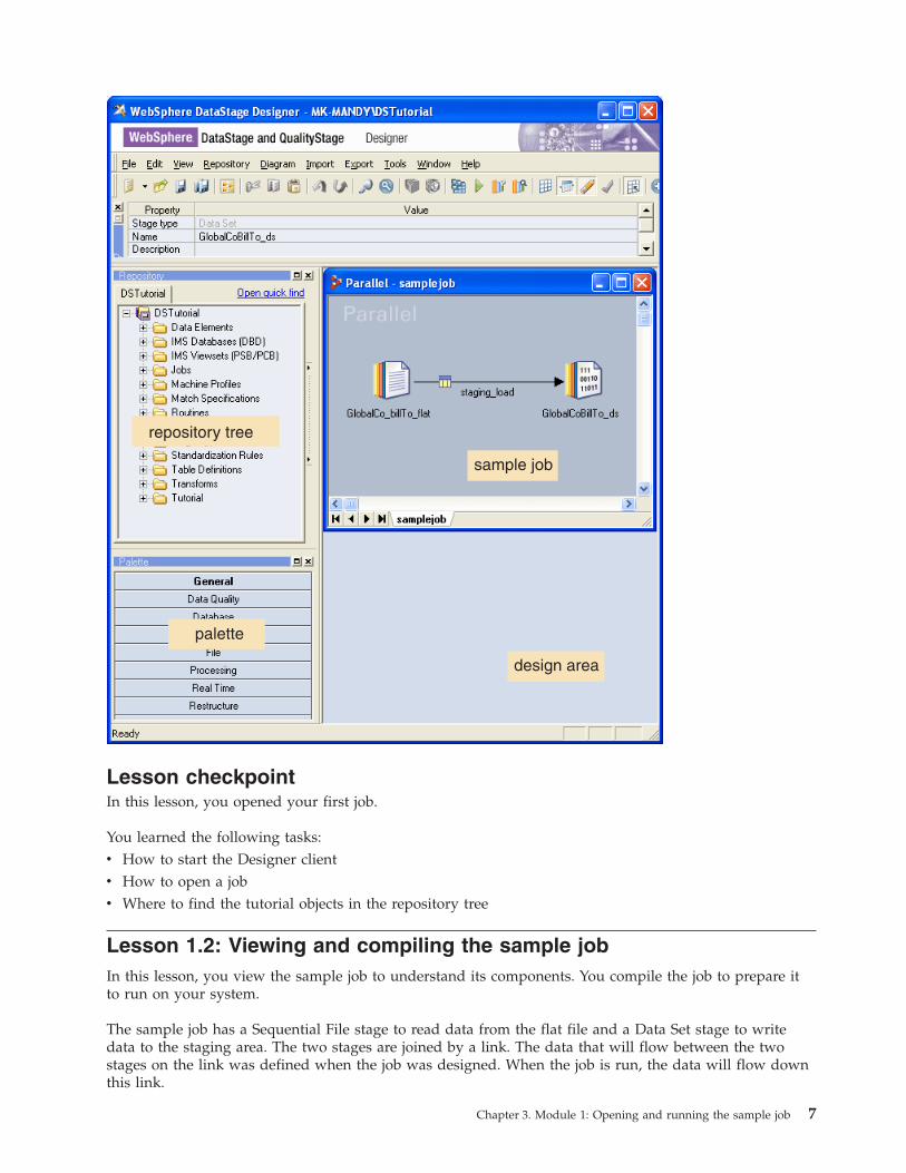
sample job
design area
repository tree
palette
Lesson checkpoint
In this lesson, you opened your first job.
You learned the following tasks:
v How to start the Designer client
v How to open a job
v Where to find the tutorial objects in the repository tree
Lesson 1.2: Viewing and compiling the sample job
In this lesson, you view the sample job to understand its components. You compile the job to prepare it
to run on your system.
The sample job has a Sequential File stage to read data from the flat file and a Data Set stage to write
data to the staging area. The two stages are joined by a link. The data that will flow between the two
stages on the link was defined when the job was designed. When the job is run, the data will flow down
this link.
Chapter 3. Module 1: Opening and running the sample job 7
Exploring the Sequential File stage
To explore the Sequential File stage:
1. In the sample job, double-click the Sequential File stage that is named GlobalCo_billTo_flat. The
stage editor opens to the Properties tab of the Output page. All parallel job stages have properties
tabs. You use the properties tab to specify the actions that the stage performs when the job is run.
2. Look at the File property under the Source category. You use this property to specify the file that the
stage will read when the job runs. In the sample job, the File property points to a file called
GlobalCo_BillTo.csv. You specify the directory that contains this file when you run the job. The name
of the directory has been defined as a job parameter named #tutorial_direct#, the # characters show
that the name is a job parameter. Job parameters are used to so that variable information (for
example, file name or directory name) can be specified when the job runs rather than when the job is
designed.
3. Look at the First Line is Column Names property under the Options category. In the sample job,
this property is set to True because the first line of the GlobalCo_BillTo.csv file contains the names of
the columns in the file. The remaining properties have default values.
4. Click on the Format tab. The Format tab looks similar to the Properties tab, but the properties that
the job designer sets here describe the format of the flat file that the stage reads. In this case the file
is comma-delimited, which means that each field within a row is separated by a comma character.
The Format tab also specifies that the file has DOS line endings. This setting means that the file can
be read even when the file resides on a UNIX system.
5. Click the Columns tab. The Columns tab is where the column metadata for the stage is defined. The
column metadata defines the data that will flow down the link to the Data Set stage when the job
runs. The GlobalCo_BillTo.csv file contains many columns. All of these columns have the data type
VarChar. As you work through the tutorial, you will apply stricter data typing to these columns to
cleanse the data.
6. Click the View Data tab in the top right corner of the stage editor window.
7. In the Value field of the Resolve Job Parameter window, specify the name of the directory in which
the tutorial data was installed and click OK (you have to specify directory path whenever you view
data or run the job).
8. In the Data Browser window, click OK. A window opens that shows the first 100 rows of the data
that the GlobalCo_BillTo.csv file contains (100 rows is the default setting, but you can change it).
9. Click Close to close the Data Browser window.
10. Click OK to close the Sequential File stage editor.
Exploring the Data Set stage
To explore the Data Set stage:
1. In the sample job, double-click the Data Set stage that is named GlobalCoBillTo_ds. The stage editor
opens in the Properties tab of the Input page.
2. Look at the File property under the Target category. This property is used to specify the control file
for the data set that the stage will write the data to when the job runs. In the sample job, the File
property points to a file that is named GlobalCo_BillTo.ds. You specify the directory that contains this
file when you run the job. A data set is the internal format for transferring data inside parallel jobs.
Data Set stages are used to land data that will be used by another job.
3. Click on the Columns tab. The column metadata for this stage is the same as the column metadata for
the Sequential File stage and defines the data that the job will write to the data set.
4. Click OK to close the stage editor.
8 Parallel Job Primer
The Data Set stage editor does not have a Format tab because the data set does not require any
formatting data. Although the View Data button is available on this tab, there is no data for this stage
yet. If you click the View Data button, you will receive a message that no data exists. The data gets
created when the job runs.
Compiling the sample job
To compile the sample job:
1. Select File → Compile. The Compile Job window opens. As the job is compiled, the window is
updated with messages from the compiler.
2. When the Compile Job window displays a message that the job is compiled, click OK.
The sample job is now compiled and ready to run.
Lesson checkpoint
In this lesson, you explored a simple data extraction job that reads data from a file and writes it to a
staging area.
You learned the following tasks:
v How to open stage editors
v How to view the data that a stage represents
v How to compile a job so that it is ready to run
Lesson 1.3: Running the sample job
In this lesson, you use the Director client to run the sample job and to view the log that the job produces
as it runs. You also use the Designer client to look at the data set that is written by the sample job.
You run the job from the Director client. The Director client is the operating console. You use the Director
client to run and troubleshoot jobs that you are developing in the Designer client. You also use the
Director client to run fully developed jobs in the production environment.
You use the job log to debug any errors you receive when you run the job.
Running the job
To run the job:
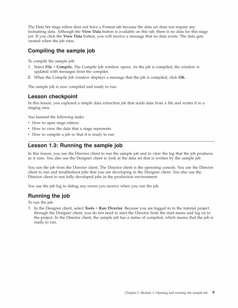
1. In the Designer client, select Tools → Run Director. Because you are logged in to the tutorial project
through the Designer client, you do not need to start the Director from the start menu and log on to
the project. In the Director client, the sample job has a status of compiled, which means that the job is
ready to run.
Chapter 3. Module 1: Opening and running the sample job 9
2. Select the sample job in the right pane of the Director client, and select Job → Run Now.
3. In the Job Run Options window, specify the path of the project folder (for example,
C:\IBM\InformationServer\Server\Projects\Tutorial and click Run. The job status changes to
Running.
4. When the job status changes to Finished, select View → Log.
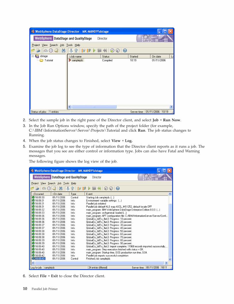
5. Examine the job log to see the type of information that the Director client reports as it runs a job. The
messages that you see are either control or information type. Jobs can also have Fatal and Warning
messages.
The following figure shows the log view of the job.
6. Select File → Exit to close the Director client.
10 Parallel Job Primer
Viewing the data set
To view the data set that the job created:
1. In the sample job in the Designer client, double-click the Data Set stage to open the stage editor.
2. In the stage editor, click View Data.
3. Click OK in the Data Browser window to accept the default settings. A window opens that shows up
to 100 rows of the data written to the data set (if you want to view more than 100 rows in a data
browser, change the default settings before you click OK).
4. Click Close to close the Data Browser window.
5. Click OK to close the Data Set stage.
Lesson checkpoint
In this lesson you ran the sample job and looked at the results.
You learned the following tasks:
v How to start the Director client from the Designer client
v How to run a job and look at the log file
v How to view the data written by the job
Module 1: Summary
You have now opened, compiled, and run your first data extraction job.
Now that you have run a data extraction job, you can start creating your own jobs. The next module
guides you through the process of creating a simple job that does more data extraction.
Lessons learned
By completing this module, you learned about the following concepts and tasks:
v Starting the Designer client.
v Opening an existing job.
v Compiling the job.
v Starting the Director client from the Designer client.
v Running the sample job.
v Viewing the results of the sample job and seeing how the job extracts data from a comma-separated file
and writes it to a staging area.
Additional resources
For more information about the features that you have learned about, see the following guides:
v IBM WebSphere DataStage Designer Client Guide
v IBM WebSphere DataStage Director Client Guide
Chapter 3. Module 1: Opening and running the sample job 11

12 Parallel Job Primer
Chapter 4. Module 2: Designing your first job
This module teaches you how to design your own job.
The job that you design will read two flat files and populate two lookup tables. The two lookup tables
will be used by a more complex job that you will create in the next module.
Learning objectives
After completing the lessons in this module, you will understand how to do the following tasks:
v Add stages and links to a job.
v Specify the properties of the stages and links to determine what they will do when the job is run.
v Learn how to specify column metadata.
v Consolidate your knowledge of compiling and running jobs.
This module should take approximately 90 minutes to complete.
Lesson 2.1: Creating a job
The first step in designing a job is to create an empty job and save it to a folder in the repository.
If you closed the Designer client after completing module 1, you will need to start the Designer client
again.
You create a parallel job and save it to a new folder in the Tutorial folder in the repository tree.
To create a job:
1. In the Designer client, select File → New.
2. In the New window, select the Jobs folder in the left pane and then select the parallel job icon in the
right pane.
3. Click OK. A new empty job design window opens in the design area.
4. Select File → Save.
5. In the Save Parallel Job As window, right-click on the Tutorial folder and select New → Folder from
the shortcut menu.
6. Type in a name for the folder, for example, My Jobs then move to the Item name field.
7. Type in the name of the job in the Item name field. Call the job populate_cc_spechand_lookupfiles.
8. Check that the Folder path field contains the path \Tutorial\My Jobs, then click Save.
You have created a new parallel job named populate_cc_spechand_lookupfiles and saved it in the folder
Tutorial\My Jobs in the repository.
Lesson checkpoint
In this lesson you created a job and saved it to a specified place in the repository.
You learned the following tasks:
v How to create a job in the Designer client.
v How to name the job and save it to a folder in the repository tree.
© Copyright IBM Corp. 2006 13
Lesson 2.2: Adding stages and links to the job
You add stages and links to the job that you created. Stages and links are the building blocks that
determine what the job does when it runs.
The job design
In this lesson, you will build the first part of the job, then compile it and run it to ensure that it works
correctly before you add the next part of the job design. This method of iterative job design is a good
habit to get into. You ensure that each part of your job is functional before you continue with the design
for the next part.
The first part of the job reads a comma-separated file that contains a series of customer numbers, a
corresponding code that identifies the country in which the customers are located, and another code that
specifies the customer’s language. You are designing a job that reads the comma-separated file and writes
the contents to a lookup table in a lookup file set. This table will be used by a subsequent job when it
populates a dimension table.
Adding stages and linking them
Ensure that the job named populate_cc_spechand_lookupfiles that you created in lesson 1 is open and
active in the job design area. A job is active when the title bar is dark blue (if you are using the default
Windows colors).
A job consists of stages linked together which describe the flow of data from a data source to a data
target. A stage is a graphical representation of the data itself, or of a transformation that will be
performed on that data.
To add the stages to your job design:
1. In the Designer client palette area, click the File bar to open the file section of the palette.
2. In the file section of the palette, select the Lookup File Set stage icon and drag the stage to your open
job. Position the stage on the right side of the job window
3. In the file section of the palette, select the Sequential File stage icon and drag the stage to your open
job. Position the stage on the left side of the job window.
4. Select the Sequential File stage in the job window. In the palette area, click the General bar to open
the general section of the palette.
5. Select the Link icon and move your mouse pointer over to the Sequential File stage. The mouse
pointer changes to a target shape.
6. Click the Sequential file stage to anchor the link and then drag the mouse pointer over to the Lookup
File Set stage. A link is drawn between the two stages. Your data will flow down this link when the
job runs.
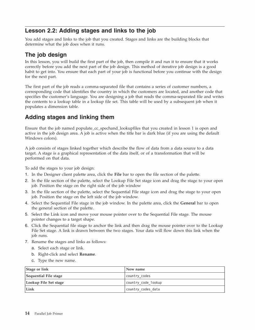
7. Rename the stages and links as follows:
a. Select each stage or link.
b. Right-click and select Rename.
c. Type the new name.
Stage or link New name
Sequential File stage country_codes
Lookup File Set stage country_code_lookup
Link country_codes_data
14 Parallel Job Primer
Always use specific names for your stages and links rather than the default names assigned by the
Designer client. Using specific names make your job designs easier to document and easier to
maintain.
8. Select File → Save to save the job.
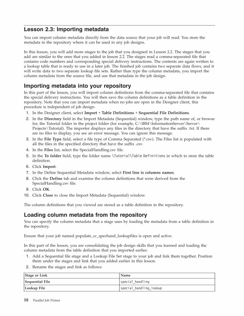
Your job design should now look something like the one shown in this figure:
Specifying properties and column metadata for the Sequential File
stage
You will now edit the first of the stages that you added to specify what the stage does when you run the
job. You will also specify the column metadata for the data that will flow down the link that joins the
two stages.
To edit the stages and add properties and metadata:
1. Double-click the country_codes Sequential File stage to open the stage editor. The editor opens in the
Properties tab of the Output page.
2. Select the File property under the Source category.
3. In the File field, type the path name for your project folder (where the data files were copied when
the tutorial was set up) and add the name CustomerCountry.csv (for example C:\IBM\InformationServer\Server\Projects\Tutorial\CustomerCountry.csv), and then press enter. (You can
browse for the path name if you prefer, click the browse button on the right of the File field.) You
specified the name of the comma-separated file that the stage reads when the job runs.
4. Select the First Line is Column Name property under the Options category.
5. Click the down arrow next to the First Line is Columns Names field and select True from the list.
The row that contains the column names is dropped when the job reads the file.
6. Click the Format tab.
7. In the record-level category, select the Record delimiter string property from the Available
properties to add.
8. Select DOS format from the Record delimiter string list. This setting ensures that the file can be read
by UNIX or Linux® WebSphere DataStage servers.
9. Click the Columns tab. Because the CustomerCountry.csv file contains only three columns, type the
column definitions into the Columns tab. (If a file contains many columns, it is less time consuming
Chapter 4. Module 2: Designing your first job 15
and more accurate to import the column definitions directly from the data source.) Note that column
names are case-sensitive, so use the case in the instructions.
10. Double-click the first line of the table. Fill in the fields as follows:
Column Name Key SQL Type Length Description
CUSTOMER_
NUMBER
Yes Char 7 Key column for the
look up - the
customer identifier
You will use the default values for the remaining fields.
11. Add two more rows to the table to specify the remaining two columns and fill them in as follows:
Column Name Key SQL Type Length Description
COUNTRY No Char 2 The code that
identifies the
customer’s country
LANGUAGE No Char 2 The code that
identifies the
customer’s language
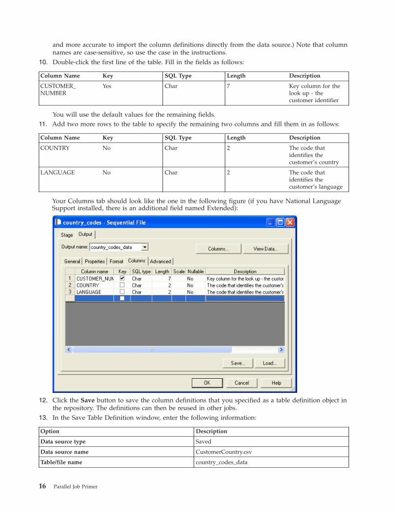
Your Columns tab should look like the one in the following figure (if you have National Language
Support installed, there is an additional field named Extended):
12. Click the Save button to save the column definitions that you specified as a table definition object in
the repository. The definitions can then be reused in other jobs.
13. In the Save Table Definition window, enter the following information:
Option Description
Data source type Saved
Data source name CustomerCountry.csv
Table/file name country_codes_data
16 Parallel Job Primer
Option Description
Short description date and time of saving
Long description Table definition for country codes source file
14. Click OK to specify the locator for the table definition. The locator identifies the table definition.
15. In the Save Table Definition As window, save the table definition in the Tutorial folder and name it
country_codes_data.
16. Click the View Data button and click OK in the Data Browser window to use the default settings.
The data browser shows you the data that the CustomerCountry.csv file contains. Since you specified
the column definitions, the Designer client can read the file and show you the results.
17. Close the Data Browser window.
18. Click OK to close the stage editor.
19. Save the job.
Notice that a small table icon has appeared on the Country_codes_data link. This icon shows that the link
now has metadata. You have designed the first part of your job.
Specifying properties for the Lookup File Set stage and running the
job
In this part of the lesson, you configure the next stage in your job. You already specified the column
metadata for data that will flow down the link between the two stages, so there are fewer properties to
specify in this task.
To configure the Lookup File Set stage:
1. Double-click the country_code_lookup Lookup File Set stage to open the stage editor. The editor
opens in the Properties tab of the Input page.
2. Select the Lookup Keys category; then double-click the Key property in the Available Properties to
add area.
3. In the Key field, click the down arrow and select CUSTOMER_NUMBER from the list and press
enter. You specified that the CUSTOMER_NUMBER column will be the lookup key for the lookup
table that you are creating.
4. Select the Lookup File Set property under the Target category.
5. In the Lookup File Set field, type the path name for the lookup file set that the stage will create, (for
example, C:\IBM\InformationServer\Server\Projects\Tutorial\countrylookup.fs) and press enter.
6. Click OK to save your property settings and close the Lookup File Set stage editor.
7. Save the job and then compile and run the job by using the techniques that you learned in Lesson 1.
You have now written a lookup table that can be used by another job later on in the tutorial.
Lesson checkpoint
You have now designed and run your very first job.
You learned the following tasks:
v How to add stages and links to a job
v How to set the stage properties that determine what the stage will do when you run the job
v How to specify column metadata for the job and to save the column metadata to the repository for use
in other jobs
Chapter 4. Module 2: Designing your first job 17
Lesson 2.3: Importing metadata
You can import column metadata directly from the data source that your job will read. You store the
metadata in the repository where it can be used in any job designs.
In this lesson, you will add more stages to the job that you designed in Lesson 2.2. The stages that you
add are similar to the ones that you added in lesson 2.2. The stages read a comma-separated file that
contains code numbers and corresponding special delivery instructions. The contents are again written to
a lookup table that is ready to use in a later job. The finished job contains two separate data flows, and it
will write data to two separate lookup file sets. Rather than type the column metadata, you import the
column metadata from the source file, and use that metadata in the job design.
Importing metadata into your repository
In this part of the lesson, you will import column definitions from the comma-separated file that contains
the special delivery instructions. You will then save the column definitions as a table definition in the
repository. Note that you can import metadata when no jobs are open in the Designer client, this
procedure is independent of job design.
1. In the Designer client, select Import → Table Definitions → Sequential File Definitions.
2. In the Directory field in the Import Metadata (Sequential) window, type the path name of, or browse
for, the Tutorial folder in the project folder (for example, C:\IBM\InformationServer\Server\Projects\Tutorial). The importer displays any files in the directory that have the suffix .txt. If there
are no files to display, you see an error message. You can ignore this message.
3. In the File Type field, select a file type of Comma Separated (*.csv). The Files list is populated with
all the files in the specified directory that have the suffix .csv.
4. In the Files list, select the SpecialHandling.csv file.
5. In the To folder field, type the folder name \Tutorial\Table Definitions in which to store the table
definition.
6. Click Import.
7. In the Define Sequential Metadata window, select First line is columns names.
8. Click the Define tab and examine the column definitions that were derived from the
SpecialHandling.csv file.
9. Click OK.
10. Click Close to close the Import Metadata (Sequential) window.
The column definitions that you viewed are stored as a table definition in the repository.
Loading column metadata from the repository
You can specify the column metadata that a stage uses by loading the metadata from a table definition in
the repository.
Ensure that your job named populate_cc_spechand_lookupfiles is open and active.
In this part of the lesson, you are consolidating the job design skills that you learned and loading the
column metadata from the table definition that you imported earlier.
1. Add a Sequential file stage and a Lookup File Set stage to your job and link them together. Position
them under the stages and link that you added earlier in this lesson.
2. Rename the stages and link as follows:
Stage or Link Name
Sequential File special_handling
Lookup File special_handling_lookup
18 Parallel Job Primer
Stage or Link Name
Link special_handling_data
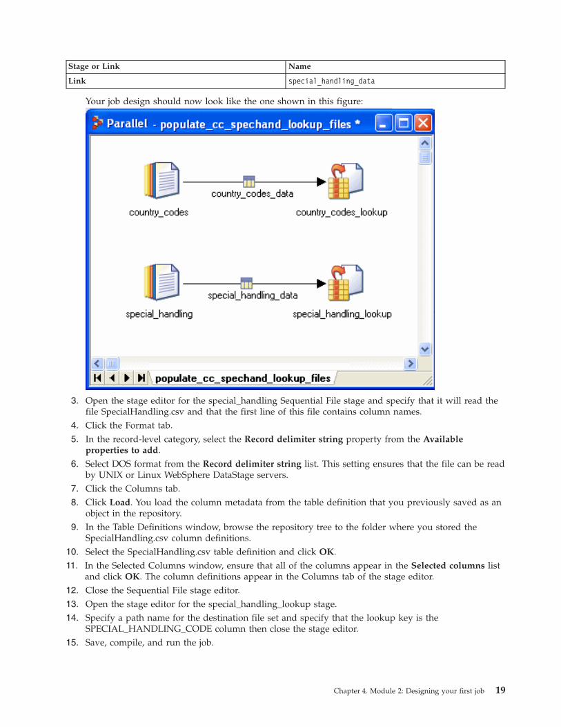
Your job design should now look like the one shown in this figure:
3. Open the stage editor for the special_handling Sequential File stage and specify that it will read the
file SpecialHandling.csv and that the first line of this file contains column names.
4. Click the Format tab.
5. In the record-level category, select the Record delimiter string property from the Available
properties to add.
6. Select DOS format from the Record delimiter string list. This setting ensures that the file can be read
by UNIX or Linux WebSphere DataStage servers.
7. Click the Columns tab.
8. Click Load. You load the column metadata from the table definition that you previously saved as an
object in the repository.
9. In the Table Definitions window, browse the repository tree to the folder where you stored the
SpecialHandling.csv column definitions.
10. Select the SpecialHandling.csv table definition and click OK.
11. In the Selected Columns window, ensure that all of the columns appear in the Selected columns list
and click OK. The column definitions appear in the Columns tab of the stage editor.
12. Close the Sequential File stage editor.
13. Open the stage editor for the special_handling_lookup stage.
14. Specify a path name for the destination file set and specify that the lookup key is the
SPECIAL_HANDLING_CODE column then close the stage editor.
15. Save, compile, and run the job.
Chapter 4. Module 2: Designing your first job 19
Lesson checkpoint
You have now added to your job design and learned how to import the metadata that the job uses.
You learned the following tasks:
v How to import column metadata directly from a data source
v How to load column metadata from a definition that you saved in the repository
Lesson 2.4: Adding job parameters
When you use job parameters in your job designs, you create a better job design.
Job parameters
Sometimes, you want to specify information when you run the job rather than when you design it. In
your job design, you can specify a job parameter to represent this information. When you run the job,
you are then prompted to supply a value for the job parameter.
You specified the location of four files in the job that you designed in Lesson 2.3. In each part of the job,
you specified a file that contains the source data and a file to write the lookup data set to. In this lesson,
you will replace all four file names with job parameters. You will then supply the actual path names of
the files when you run the job.
You will save the definitions of these job parameters in a parameter set in the repository. When you want
use the same job parameters in a job later on in this tutorial, you can load them into the job design from
the parameter set. Parameter sets enable the same job parameters to be used by different jobs.
Defining job parameters
Ensure that the job named populate_cc_spechand_lookupfile that you designed in Lesson 2.3 is open and
active.
1. Select Edit → Job Properties.
2. In the Job Properties window, click the Parameters tab.
3. Double-click the first line of the grid to add a new row.
4. In the Parameter name field, type country_codes_source.
5. In the Prompt field, type path name for the country codes file.
6. In the Type field, select the path name datatype.
7. In the Help Text field, type Enter the path name for the comma-separated file that contains the
country code definitions.
8. Repeat steps 3-7 to define three more job parameters containing the following entries:
Parameter Name Prompt Type Help text
country_codes_lookup path name for the country
codes lookup file set
path name Enter the path name for
the file set for the
country code lookup table
special_handling_source path name for the special
handling codes file
path name Enter the path name for
the comma-separated file
that contains the special
handling code definitions
special_handling_lookup path name for the special
handling lookup file set
path name Enter the path name for
the file set for the
special handling lookup
table
20 Parallel Job Primer
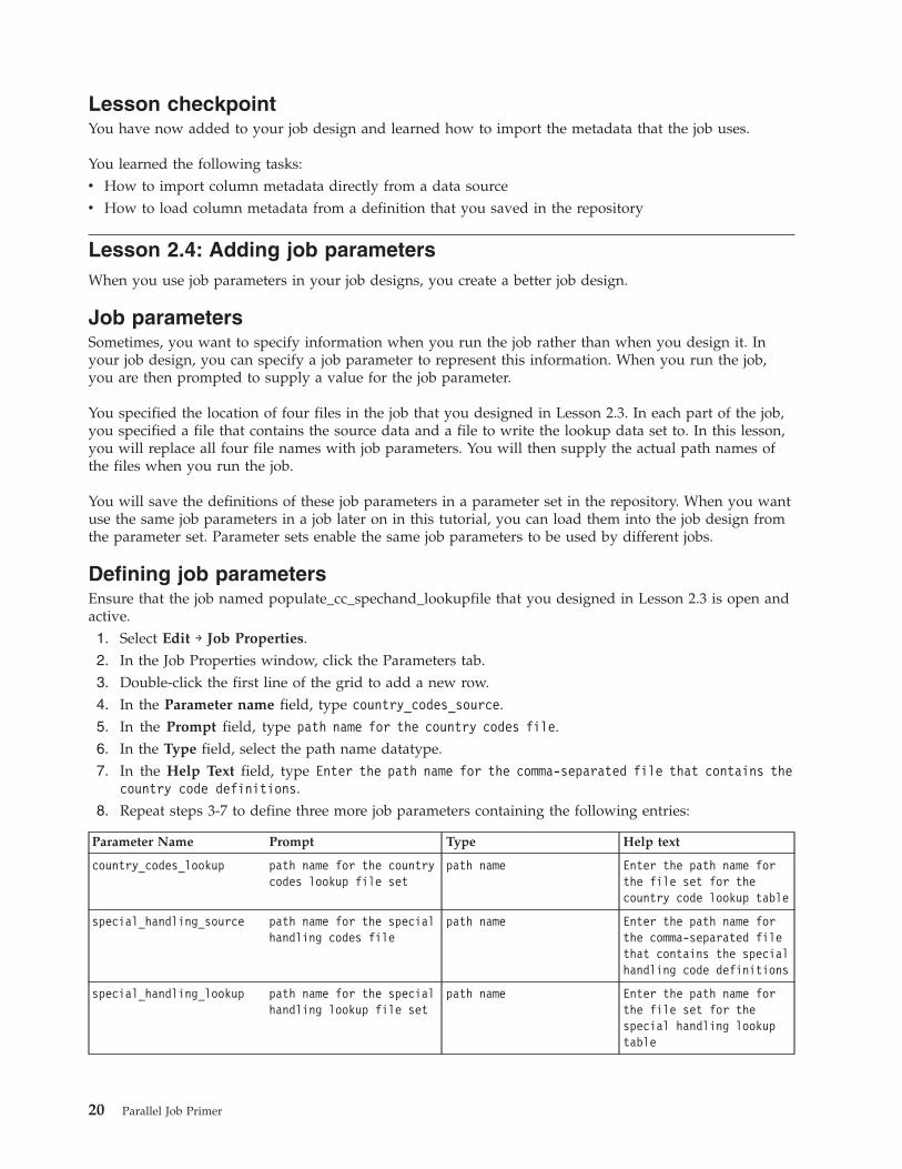
The Parameters tab of the Job Properties window should now look like the one in the following
figure:
9. Click OK to close the Job Properties window.
10. Click File → Save to save the job.
Adding job parameters to your job design
Now that you have defined the job parameters, you will add them to your job design.
1. Double-click the country_codes Sequential File stage to open the stage editor.
2. Select the File property in the Source category and delete the path name that you entered in the File
field.
3. Click the right arrow next to the File field, and select Insert Job Parameter from the menu.
4. Select country_codes_source from the list and press enter. The text #country_codes_source# appears
in the File field. This text specifies that the job will request the name of the file when you run the job.
5. Repeat these steps for each of the stages in the job, specifying job parameters for each of the File
properties as follows:
Stage Property Parameter name
country_codes_lookup stage Lookup file set country_codes_lookup
special_handling stage File special_handling_source
special_handling_lookup stage Lookup file set special_handling_lookup
6. Save and recompile the job.
Supplying values for the job parameters
When you run the job, the Director client prompts you to supply values for the job parameters.
1. Open the Director client.
2. Select your job name and select Job → Run Now.
3. In the Parameters page of the Job Run Options window, type a path name for each of the job
parameters.
4. Click Run.
Chapter 4. Module 2: Designing your first job 21
The job runs, using the values that you supplied for the job parameters.
Lesson checkpoint
You defined job parameters to represent the file names in your job and specified values for these
parameters when you ran the job.
You learned the following tasks:
v How to define job parameters
v How to add job parameters in your job design
v How to specify values for the job parameters when you run the job
Lesson 2.5: Creating parameter sets
You can store job parameters in a parameter set in the repository. You can then reuse the job parameters
in other job designs.
In this lesson, you will create a parameter set from the job parameters that you created in Lesson 2.4. You
will also supply a set of default values for the parameters in the parameter set that are also available
when the parameter set is used.
Parameter sets
You use parameter sets to define job parameters that you are likely to reuse in other jobs. Whenever you
need this set of parameters in a job design, you can insert them into the job properties from the
parameter set. You can also define different sets of values for each parameter set. These parameter sets
are stored as files in the WebSphere DataStage server installation directory and are available to use in
your job designs or when you run jobs that use these parameter sets. If you make any changes to a
parameter set object, these changes are reflected in job designs that use this object until the job is
compiled. The parameters that a job is compiled with are available when the job is run. However, if you
change the design after the job is compiled, the job will link to the current version of the parameter set.
You can create parameter sets from existing job parameters, or you can specify the job parameters as part
of the task of creating a new parameter set.
Creating a parameter set from existing job parameters
Ensure that your job is open and active.
1. Select Edit → Job Properties.
2. In the Job Properties window, click the Parameters tab.
3. In the Parameters page, use shift-click to select all of the job parameters that you defined in Lesson
2.4.
4. Click Create Parameter Set.
5. In the General page of the Parameter Set window, type a name for the parameter set and a short
description (for example, tutorial_lookup and parameter set for lookup file names).
6. Click the Parameters tab and check that all the job parameters that you specified for your job appear
in this page.
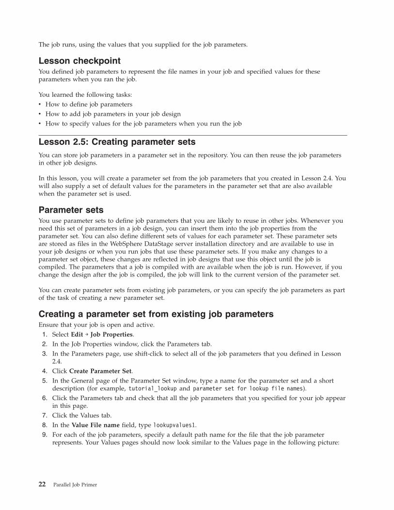
7. Click the Values tab.
8. In the Value File name field, type lookupvalues1.
9. For each of the job parameters, specify a default path name for the file that the job parameter
represents. Your Values pages should now look similar to the Values page in the following picture:
22 Parallel Job Primer
10. Click OK, specify a repository folder in which to store the parameter set, and then click Save.
11. The Designer client asks if you want to replace the selected parameters with the parameter set that
you have just created. Click No.
12. Click OK to close the Job Parameters window.
13. Save the job.
You created a parameter set that is available for another job that you will create later in this tutorial. The
current job continues to use the individual parameters rather than the parameter set.
Lesson checkpoint
You have now created a parameter set.
You learned the following tasks:
v How to create a parameter set from a set of existing job parameters
v How to specify a set of default values for the parameters in the parameter set
Module 2 Summary
In this module, you designed and ran a data extraction job.
You also learned how to create reusable objects such as table definitions and parameters sets that you can
include in other jobs that you design.
Lessons learned
By completing this module, you learned about the following concepts and tasks:
v Creating new jobs and saving them in the repository
v Adding stages and links and specifying their properties
v Specifying column metadata and saving it as a table definition to reuse later
v Specifying job parameters to make your job design more flexible, and saving the parameters in the
repository to reuse later
Chapter 4. Module 2: Designing your first job 23

24 Parallel Job Primer

Chapter 5. Module 3: Designing a transformation job
This module teaches you how to design a job that transforms data.
The job that you design will read the GlobalCo bill_to data that was written to a data set when you ran
the sample job in Module 1 of this tutorial. Your job will perform some simple cleansing of the data. Your
job will transform the data by dropping the columns that you do not need and by trimming some of the
data in the columns that you do need.
Learning objectives
After completing the lessons in this module, you will understand how to do the following tasks:
v How to use a Transformer stage to transform data
v How to handle rejected data
v How to combine data by using a Lookup stage
This module should take approximately 60 minutes to complete.
Lesson 3.1: Designing the transformation job
You will design and run a job that performs some simple transformations on the bill_to data, and writes
the results to a staging Data Set stage.
The transformer job
The data that was read from the GlobalCo_BillTo.csv comma-separated file by the sample job in Module
1 contains a large number of columns. The dimension table that you will produce later in this tutorial
requires only a subset of these columns, so you will use the transformation job to drop some of the
columns.
The job will also specify some stricter data typing for the remaining columns. Stricter data typing helps
to impose quality controls on the data that you are processing.
Finally, the job applies a function to one of the data columns to delete space characters that the column
contains. This transformation job prepares the data in that column for a later operation.
The transformation job that you are designing uses a Transformer stage, but there are also several other
types of processing stages available in the Designer client that can transform data. For example, you can
use the Modify stage in your job, if you want to change only the data types in a data set. Several of the
processing stages can drop data columns as part of their processing. In the current job, you use the
Transformer stage because you require a transformation function that you can customize. Several
functions are available to use in the Transformer stage.
Creating the transformation job and adding stages and links
In this part of the lesson, you will create your transformation job and learn a new method for performing
tasks that you are already familiar with.
1. Create a parallel job, save it as TrimAndStrip, and store it in the tutorial folder in the repository tree.
2. Add two Data Set stages to the design area.
3. Name the Data Set stage on the left GlobalCoBillTo, and name the one on the right
int_GlobalCoBillTo.
4. Click Palette → Processing to locate and drag a Transformer stage to the design area.
© Copyright IBM Corp. 2006 25
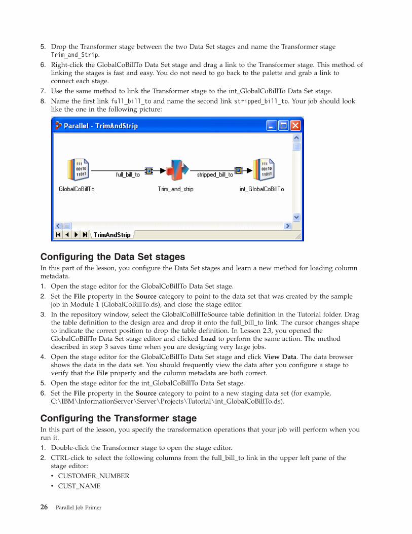
5. Drop the Transformer stage between the two Data Set stages and name the Transformer stage
Trim_and_Strip.
6. Right-click the GlobalCoBillTo Data Set stage and drag a link to the Transformer stage. This method of
linking the stages is fast and easy. You do not need to go back to the palette and grab a link to
connect each stage.
7. Use the same method to link the Transformer stage to the int_GlobalCoBillTo Data Set stage.
8. Name the first link full_bill_to and name the second link stripped_bill_to. Your job should look
like the one in the following picture:
Configuring the Data Set stages
In this part of the lesson, you configure the Data Set stages and learn a new method for loading column
metadata.
1. Open the stage editor for the GlobalCoBillTo Data Set stage.
2. Set the File property in the Source category to point to the data set that was created by the sample
job in Module 1 (GlobalCoBillTo.ds), and close the stage editor.
3. In the repository window, select the GlobalCoBillToSource table definition in the Tutorial folder. Drag
the table definition to the design area and drop it onto the full_bill_to link. The cursor changes shape
to indicate the correct position to drop the table definition. In Lesson 2.3, you opened the
GlobalCoBillTo Data Set stage editor and clicked Load to perform the same action. The method
described in step 3 saves time when you are designing very large jobs.
4. Open the stage editor for the GlobalCoBillTo Data Set stage and click View Data. The data browser
shows the data in the data set. You should frequently view the data after you configure a stage to
verify that the File property and the column metadata are both correct.
5. Open the stage editor for the int_GlobalCoBillTo Data Set stage.
6. Set the File property in the Source category to point to a new staging data set (for example,
C:\IBM\InformationServer\Server\Projects\Tutorial\int_GlobalCoBillTo.ds).
Configuring the Transformer stage
In this part of the lesson, you specify the transformation operations that your job will perform when you
run it.
1. Double-click the Transformer stage to open the stage editor.
2. CTRL-click to select the following columns from the full_bill_to link in the upper left pane of the
stage editor:
v CUSTOMER_NUMBER
v CUST_NAME
26 Parallel Job Primer
v ADDR_1
v ADDR_2
v CITY
v REGION_CODE
v ZIP
v TEL_NUM
v REVIEW_MONTH
v SETUP_DATE
v STATUS_CODE3. Drag these columns from the upper left pane to the stripped_bill_to link in the upper right pane of
the stage editor. You are specifying that only these columns will flow through the Transformer stage
when the job is run. The remaining columns will be dropped.
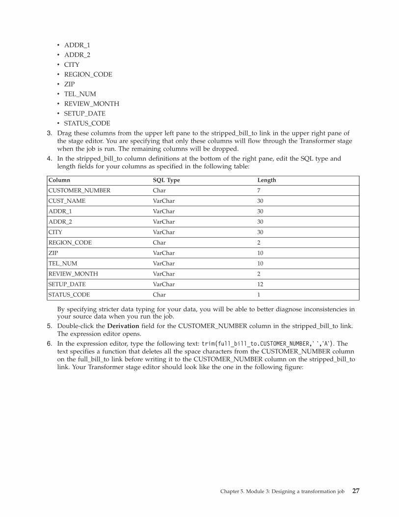
4. In the stripped_bill_to column definitions at the bottom of the right pane, edit the SQL type and
length fields for your columns as specified in the following table:
Column SQL Type Length
CUSTOMER_NUMBER Char 7
CUST_NAME VarChar 30
ADDR_1 VarChar 30
ADDR_2 VarChar 30
CITY VarChar 30
REGION_CODE Char 2
ZIP VarChar 10
TEL_NUM VarChar 10
REVIEW_MONTH VarChar 2
SETUP_DATE VarChar 12
STATUS_CODE Char 1
By specifying stricter data typing for your data, you will be able to better diagnose inconsistencies in
your source data when you run the job.
5. Double-click the Derivation field for the CUSTOMER_NUMBER column in the stripped_bill_to link.
The expression editor opens.
6. In the expression editor, type the following text: trim(full_bill_to.CUSTOMER_NUMBER,’ ’,’A’). The
text specifies a function that deletes all the space characters from the CUSTOMER_NUMBER column
on the full_bill_to link before writing it to the CUSTOMER_NUMBER column on the stripped_bill_to
link. Your Transformer stage editor should look like the one in the following figure:
Chapter 5. Module 3: Designing a transformation job 27
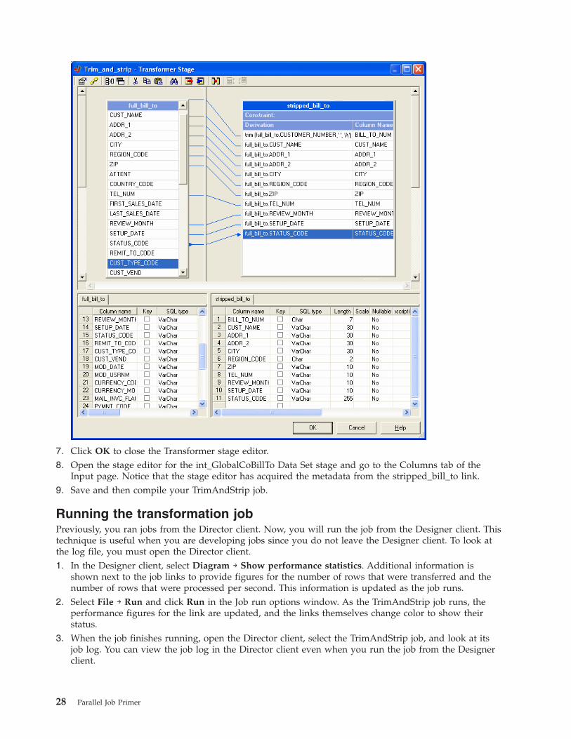
7. Click OK to close the Transformer stage editor.
8. Open the stage editor for the int_GlobalCoBillTo Data Set stage and go to the Columns tab of the
Input page. Notice that the stage editor has acquired the metadata from the stripped_bill_to link.
9. Save and then compile your TrimAndStrip job.
Running the transformation job
Previously, you ran jobs from the Director client. Now, you will run the job from the Designer client. This
technique is useful when you are developing jobs since you do not leave the Designer client. To look at
the log file, you must open the Director client.
1. In the Designer client, select Diagram → Show performance statistics. Additional information is
shown next to the job links to provide figures for the number of rows that were transferred and the
number of rows that were processed per second. This information is updated as the job runs.
2. Select File → Run and click Run in the Job run options window. As the TrimAndStrip job runs, the
performance figures for the link are updated, and the links themselves change color to show their
status.
3. When the job finishes running, open the Director client, select the TrimAndStrip job, and look at its
job log. You can view the job log in the Director client even when you run the job from the Designer
client.
28 Parallel Job Primer
Lesson checkpoint
In this lesson you learned how to design and configure a transformation job.
You learned the following tasks:
v How to configure a Transformer stage
v How to link stages using a different method for drawing links.
v How to load column metadata into a link, using a drag-and-drop operation.
v How to run a job from within the Designer client and monitor the performance of the job.
Lesson 3.2: Combining data in a job
The Designer client supports more complex jobs than the ones that you designed so far. In this lesson,
you begin to build a more complex job that combines data from two different tables.
You will base your new job on the transformation job that you created in Lesson 3.1. You will add a
Lookup stage that looks up the data that you created in Lesson 2.2.
Using a Lookup stage
Performing a lookup (search) is one way in which a job can combine data. The lookup is performed by
the Lookup stage. The Lookup stage has a stream input and a reference input. The Lookup stage uses
one or more key columns in the stream input to search for data in a reference table. The stage adds the
data from the reference table to the stream output.
You can also combine data in a parallel job by using a Join stage. Where you use a large reference table, a
job can run faster if it combines data by using a Join stage. For the job that you are designing, the
reference table is small, and so a Lookup stage is preferred. The Lookup stage is most efficient where the
data being looked up fits into the available physical memory.
You can configure Lookup stages to search for data in a Lookup file set, or they can search for data in a
relational database. The job will look up the data in a reference table in a Lookup File Set stage that was
created in Lesson 2.2 of this tutorial. When you use lookup file sets, you must specify the lookup key
column when you define the file set. You defined the key columns for the lookup tables that you used in
this lesson when you created the file sets in Module 2.
Creating a lookup job
Next, you will create a job and add some of the stages that you configured in the TrimAndStrip job that
you designed and ran in Lesson 3.1.
Ensure that the TrimAndStrip job that you created in Lesson 3.1 is open, and that you have a
multi-window view in the design area of the Designer client. In multi-window view, you can see all the
open jobs in the display area. To switch from single-window view to multi-window view, click the
minimize button in the Designer Client menu bar.
1. Create a job, name it CleansePrepare, and save it in the tutorial folder in the repository.
2. In the TrimAndStrip job, drag the mouse cursor around the stages in the job to select them and
select Edit → Copy.
3. In the CleansePrepare job, select Edit → Paste. The stages appear in the CleansePrepare job. You can
now close the TrimAndStrip job.
4. Select the Processing area in the palette and drag a Lookup stage to the CleansPrepare job. Position
the Lookup stage just below the int_GlobalCoBillTo stage and name it Lookup_Country.
5. Select the stripped_bill_to link, position the mouse cursor in the link’s arrowhead, and drag to the
Lookup stage. You moved the link with its associated column metadata to allow data to flow from
the Transformer stage to the Lookup stage.
Chapter 5. Module 3: Designing a transformation job 29
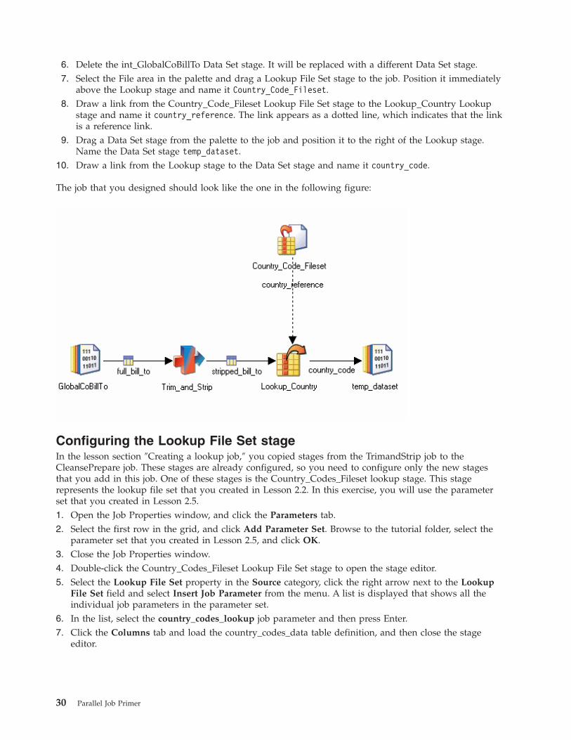
6. Delete the int_GlobalCoBillTo Data Set stage. It will be replaced with a different Data Set stage.
7. Select the File area in the palette and drag a Lookup File Set stage to the job. Position it immediately
above the Lookup stage and name it Country_Code_Fileset.
8. Draw a link from the Country_Code_Fileset Lookup File Set stage to the Lookup_Country Lookup
stage and name it country_reference. The link appears as a dotted line, which indicates that the link
is a reference link.
9. Drag a Data Set stage from the palette to the job and position it to the right of the Lookup stage.
Name the Data Set stage temp_dataset.
10. Draw a link from the Lookup stage to the Data Set stage and name it country_code.
The job that you designed should look like the one in the following figure:
Configuring the Lookup File Set stage
In the lesson section ″Creating a lookup job,″ you copied stages from the TrimandStrip job to the
CleansePrepare job. These stages are already configured, so you need to configure only the new stages
that you add in this job. One of these stages is the Country_Codes_Fileset lookup stage. This stage
represents the lookup file set that you created in Lesson 2.2. In this exercise, you will use the parameter
set that you created in Lesson 2.5.
1. Open the Job Properties window, and click the Parameters tab.
2. Select the first row in the grid, and click Add Parameter Set. Browse to the tutorial folder, select the
parameter set that you created in Lesson 2.5, and click OK.
3. Close the Job Properties window.
4. Double-click the Country_Codes_Fileset Lookup File Set stage to open the stage editor.
5. Select the Lookup File Set property in the Source category, click the right arrow next to the Lookup
File Set field and select Insert Job Parameter from the menu. A list is displayed that shows all the
individual job parameters in the parameter set.
6. In the list, select the country_codes_lookup job parameter and then press Enter.
7. Click the Columns tab and load the country_codes_data table definition, and then close the stage
editor.
30 Parallel Job Primer
Configuring the Lookup stage
You specify the data that is combined in the Lookup stage. You defined the date column that will act as
the key for the lookup when you created the lookup file set in Module 2.
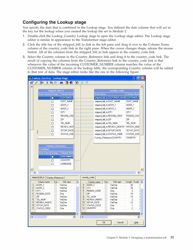
1. Double-click the Lookup_Country Lookup stage to open the Lookup stage editor. The Lookup stage
editor is similar in appearance to the Transformer stage editor.
2. Click the title bar of the stripped_bill_to link in the left pane and drag it over to the Column Name
column of the country_code link in the right pane. When the cursor changes shape, release the mouse
button. All of the columns from the stripped_bill_to link appear in the country_code link.
3. Select the Country column in the Country_Reference link and drag it to the country_code link. The
result of copying the columns from the Country_Reference link to the country_code link is that
whenever the value of the incoming CUSTOMER_NUMBER column matches the value of the
CUSTOMER_NUMBER column of the lookup table, the corresponding Country column will be added
to that row of data. The stage editor looks like the one in the following figure:
Chapter 5. Module 3: Designing a transformation job 31
4. Double-click the Condition bar in the Country_Reference link. The Lookup Stage Conditions window
opens. Select the Lookup Failure field and select Continue from the list. You are specifying that, if a
CUSTOMER_NUMBER value from the stripped_bill_to link does not match any
CUSTOMER_NUMBER column values in the reference table, the job continues to the next
CUSTOMER_NUMBER column.
5. Close the Lookup stage editor.
6. Open the temp_dataset Data Set stage and specify a file name for the data set.
7. Save, compile and run the job. The Job Run Options window displays all the parameters in the
parameter set.
8. In the Job Run Options window, select lookupvalues1 from the list next to the parameter set name.
The parameters values are filled in with the path names that you specified when you created the
parameter set.
9. Click Run to run the job and then click View Data in the temp_dataset stage to examine the results.
Lesson checkpoint
With this lesson, you started to design more complex and sophisticated jobs.
You learned the following tasks:
v How to copy stages, links, and associated configuration data between jobs.
v How to combine data in a job by using a Lookup stage.
Lesson 3.3: Capturing rejected data
This lesson shows you how to monitor rows of data that are rejected while you are processing them.
Ensure that the CleansePrepare job that you created in Lesson 3.2 is open and active.
In the Lookup stage for the job that you created in Lesson 3.2, you specified that processing should
continue on a row if the lookup operation fails. Any rows that contain CUSTOMER_NUMBER fields that
were not matched in the lookup table were bypassed, and the COUNTRY column for that row was set to
NULL. In this lesson, you will specify that non-matching rows are written to a reject link. The reject link
captures any customer numbers that do not have an entry in the country codes table. You can examine
the rejected rows and decide what action to take.
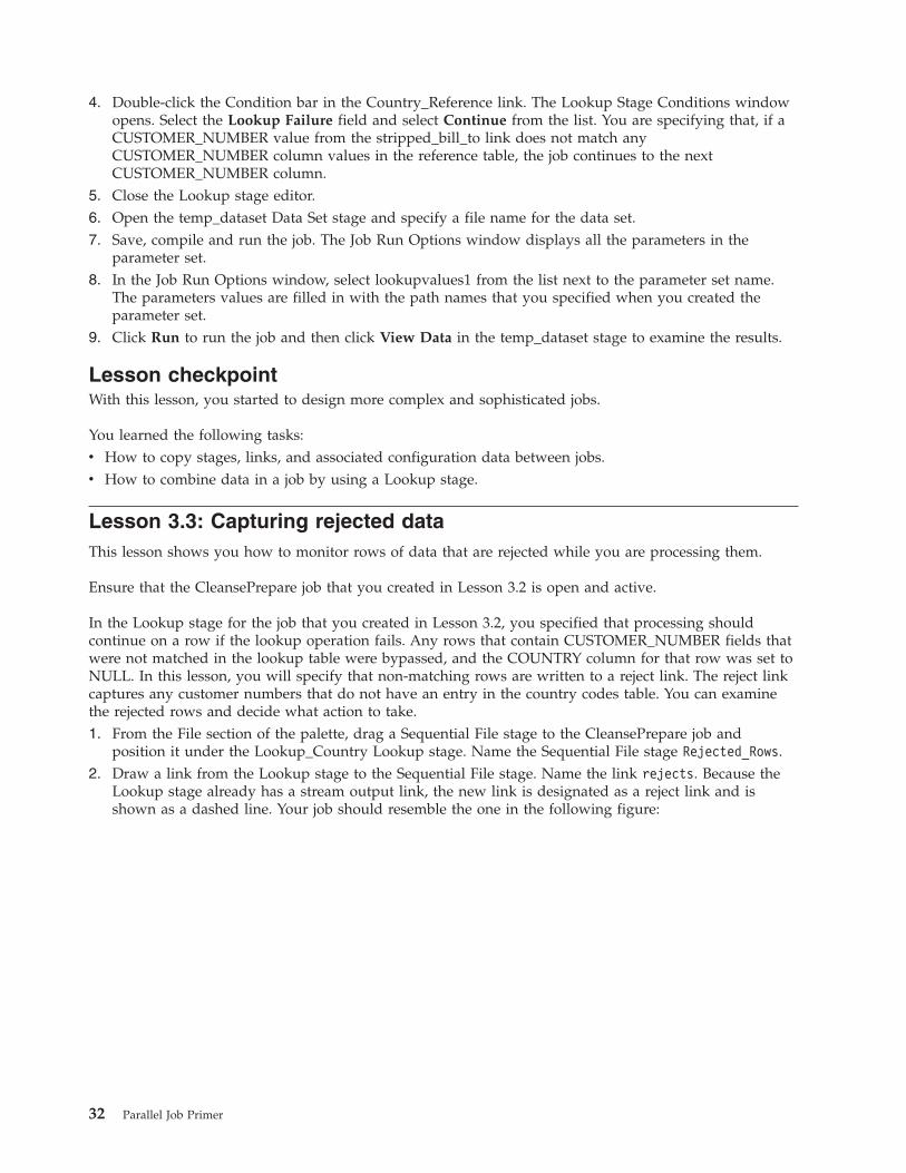
1. From the File section of the palette, drag a Sequential File stage to the CleansePrepare job and
position it under the Lookup_Country Lookup stage. Name the Sequential File stage Rejected_Rows.
2. Draw a link from the Lookup stage to the Sequential File stage. Name the link rejects. Because the
Lookup stage already has a stream output link, the new link is designated as a reject link and is
shown as a dashed line. Your job should resemble the one in the following figure:
32 Parallel Job Primer
3. Double-click the Lookup_Country Lookup stage to open the Lookup stage editor.
4. Double-Click the Condition bar in the country_reference link to open the Lookup Stage Conditions
window.
5. In the Lookup Stage Conditions window, select the Lookup Failure field and select Reject from the
list. Close the Lookup stage editor. This step specifies that, whenever a row from the stripped_bill_to
link has no matching entry in the country code lookup table, the row is rejected and written to the
Rejected_Rows Sequential File stage.
6. Edit the Rejected_Rows Sequential File stage and specify a path name for the file that the stage will
write to (for example, c:\tutorial\rejects.txt). This stage derives the column metadata from the Lookup
stage, and you cannot alter it.
7. Save, compile the CleansePrepare job, and run the job.
8. Open the Rejected_Rows Sequential File stage editor and click View Data to look at the rows that
were rejected.
Lesson checkpoint
You learned the following tasks:
v How to add a reject link to your job
v How to configure the Lookups stage so that it rejects data where a lookup fails
Lesson 3.4: Performing multiple transformations in a single job
You can design complex jobs that perform many transformation operations on your data.
In this lesson, you will further transform your data to apply some business rules and perform another
lookup of a reference table.
Chapter 5. Module 3: Designing a transformation job 33
In the sample bill_to data, one of the columns is overloaded. The SET_UP data column can contain a
special handling code as well as the date that the account was set up. The transformation logic that is
being added to the job extracts this special handling code into a separate column. The job then looks up
the text description corresponding to the code from the lookup table that you populated in Lesson 2 and
adds the description to the output data. The transformation logic also adds a row count to the output
data.
Adding new stages and links
This tasks adds the extra stages to the job that will implement the additional transformation logic.
1. Add the following stages to your CleansePrepare job:
a. Place the Transformer stage above the temp_dataset Data Set stage and name the stage
Business_Rules.
b. Place the Lookup stage immediately to the right of the temp_dataset Data Set stage and name the
Lookup stage Lookup_Spec_Handling.
c. Place the Lookup File Set stage immediately above the Lookup_Spec_Handling Lookup stage and
name the Lookup File Set stage Special_Handling_Lookup.
d. Place the Data Set stage immediately to the right of the Lookup_Spec_Handling Lookup stage and
name the Data Set stage Target.2. Link the stages:
a. Link the Business_Rules Transformer stage to the Lookup_Spec_Handling Lookup stage and name
the link with_business_rules.
b. Link the Special_Handling_Lookup Lookup File Set stage to the Lookup_Spec_Handling Lookup
stage and name the link special_handling.
c. Link the Lookup_Spec_Handling Lookup stage to the Target Data Set stage and name the link
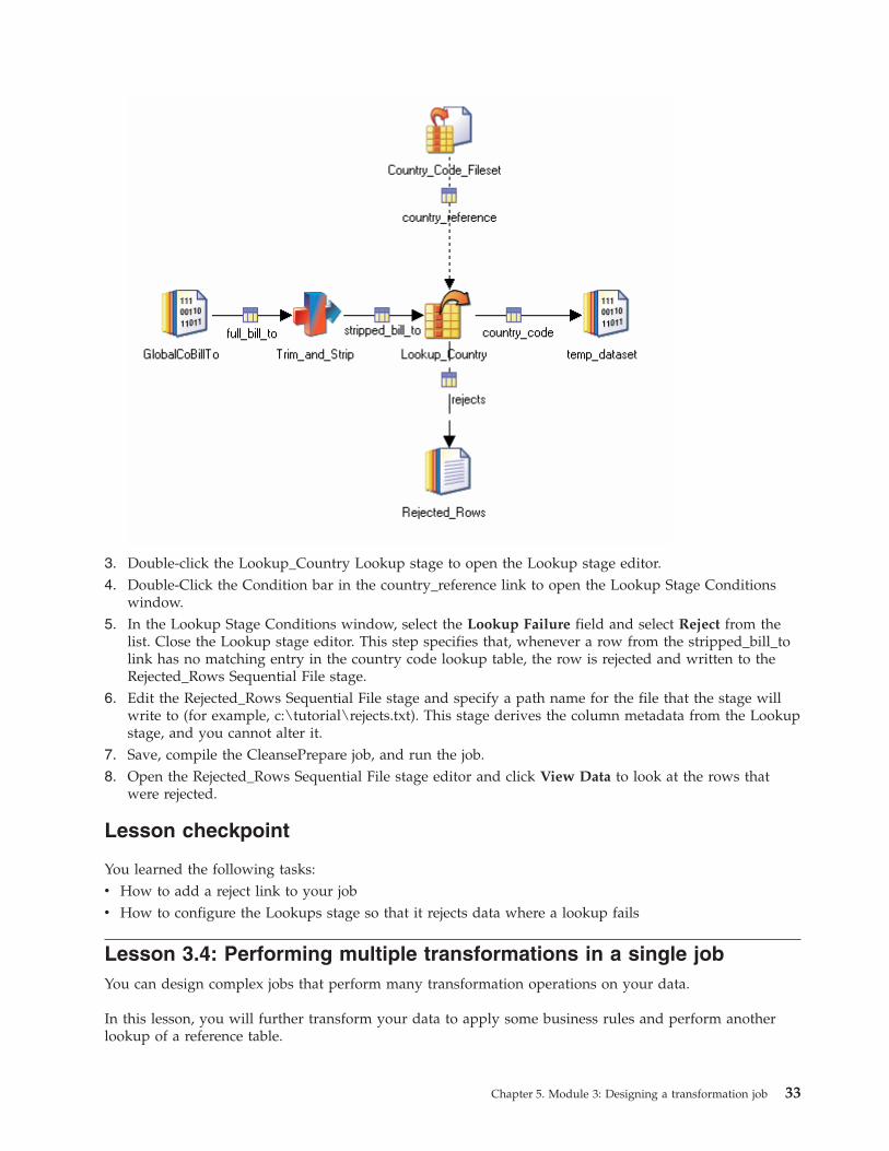
finished_data.3. Drag the arrowhead end of the country_code link and attach it to the Business_Rules Transformer
stage. The Temp_Dataset stage is not required for this job, therefore you can remove it.
4. Delete the Temp_Dataset Data Set stage.
5. Drag the Business_Rules Transformer stage down so that it aligns horizontally with the Lookup
stages. Your CleansePrepare job should now resemble the one in the following figure:
34 Parallel Job Primer

Configuring the Business_Rules Transformer stage
In this exercise, you configure the Transformer stage to extract the special handling code and add a row
count to the output data.
1. Open the Business_Rules Transformer stage editor, and click the Show/Hide Stage Variables icon to
display the stage variable grid in the right pane. You will define some stage variables later in this
procedure.
2. Select the following columns in the country_code input link and drag them to the
with_business_rules output link:
v CUSTOMER_NUMBER
v CUST_NAME
v ADDR_1
v ADDR_2
v CITY
v REGION_CODE
v ZIP
v TEL_NUM 3. In the metadata area for the with_business_rules output link, add the following new columns:
Column name SQL Type Length Nullable
SOURCE Char 10 No
RECNUM Char 10 No
SETUP_DATE Char 10 Yes
SPECIAL_HANDLING_
CODE
Integer 10 Yes
The new columns appear in the graphical representation of the link, but are highlighted in red
because they do not yet have valid derivations.
4. In the graphical area, double-click the Derivation field of the SOURCE column.
5. In the expression editor, type ’GlobalCo’:. Position your mouse pointer immediately to the right of
this text, right-click and select Input Column from the menu. Then select the COUNTRY column
from the list. When you run the job, the SOURCE column for each row will contain the two-letter
country code prefixed with the text GlobalCo, for example, GlobalCoUS.
6. In the Transformer stage editor toolbar, click the Stage Properties tool on the far left. The
Transformer Stage Properties window opens.
7. Click the Variables tab and, by using the techniques that you learned for defining table definitions,
add the following stage variables to the grid:
Name SQL Type Precision
xtractSpecialHandling Char 1
TrimDate VarChar 10
When you close the Properties window, these stage variables appear in the Stage Variables area
above the with_business_rules link.
8. Double-click the Derivation fields of each of the stage variables in turn and type the following
expressions in the expression editor:
Chapter 5. Module 3: Designing a transformation job 35
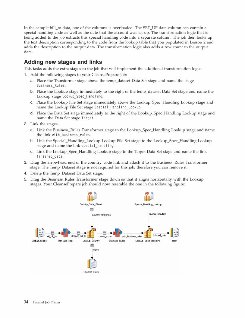
Stage variable Expression Description
xtractSpecialHandling if Len (country_code.SETUP_DATE) <
2 Then country_code.SETUP_DATE
Else Field
(country_code.SETUP_DATE,’ ’,2)
This expression checks that the
SETUP_DATE column contains a
special handling code. If it does, the
value of xtractSpecialHandling is set to
that code. If the column contains a
date and a code, the code is extracted
and the value of xtractSpecialHandling
is set to that code.
TrimDate If Len (country_code.SETUP_DATE) <
3 Then ’01/01/0001’ Else Field
(country_code.SETUP_DATE,’ ’,1)
This expression checks that the
SETUP_DATE column contains a
date. If the SETUP_DATE column
does not contain a date, then the
expression sets the value of the
TrimDate variable to the string
01/01/0001. If the SETUP_DATE
column contains a date, then the date
is extracted and the value of the
TrimDate variable is set to a string
that contains the date.
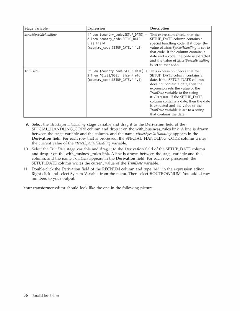
9. Select the xtractSpecialHandling stage variable and drag it to the Derivation field of the
SPECIAL_HANDLING_CODE column and drop it on the with_business_rules link. A line is drawn
between the stage variable and the column, and the name xtractSpecialHandling appears in the
Derivation field. For each row that is processed, the SPECIAL_HANDLING_CODE column writes
the current value of the xtractSpecialHandling variable.
10. Select the TrimDate stage variable and drag it to the Derivation field of the SETUP_DATE column
and drop it on the with_business_rules link. A line is drawn between the stage variable and the
column, and the name TrimDate appears in the Derivation field. For each row processed, the
SETUP_DATE column writes the current value of the TrimDate variable.
11. Double-click the Derivation field of the RECNUM column and type ’GC’: in the expression editor.
Right-click and select System Variable from the menu. Then select @OUTROWNUM. You added row
numbers to your output.
Your transformer editor should look like the one in the following picture:
36 Parallel Job Primer
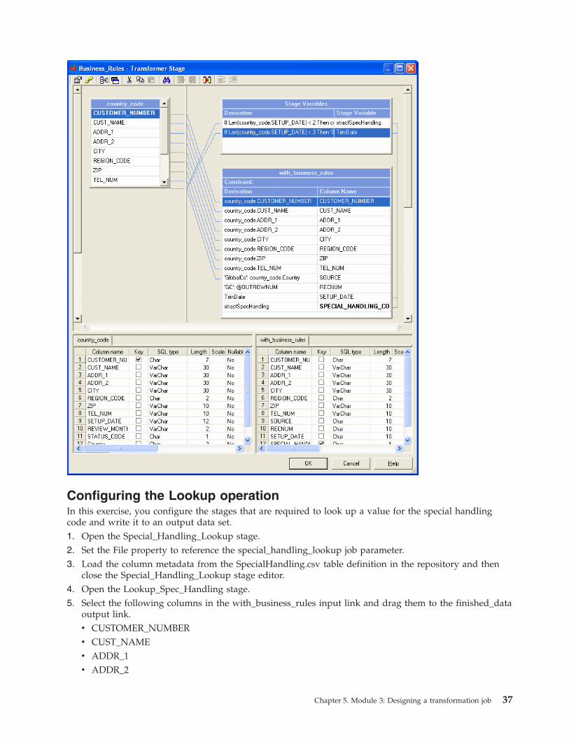
Configuring the Lookup operation
In this exercise, you configure the stages that are required to look up a value for the special handling
code and write it to an output data set.
1. Open the Special_Handling_Lookup stage.
2. Set the File property to reference the special_handling_lookup job parameter.
3. Load the column metadata from the SpecialHandling.csv table definition in the repository and then
close the Special_Handling_Lookup stage editor.
4. Open the Lookup_Spec_Handling stage.
5. Select the following columns in the with_business_rules input link and drag them to the finished_data
output link.
v CUSTOMER_NUMBER
v CUST_NAME
v ADDR_1
v ADDR_2
Chapter 5. Module 3: Designing a transformation job 37
v CITY
v REGION_CODE
v ZIP
v TEL_NUM
v SOURCE
v RECNUM
v SETUP_DATE
v SPECIAL_HANDLING_CODE6. Select the DESCRIPTION column in the special_handling reference link and drag it to the
finished_data output link (the LANGUAGE column is not used).
7. Double-click the Condition bar in the special_handling reference link to open the Lookup Stage
Conditions window. Specify that the processing will continue if the lookup fails for a data row. You
do not need to specify a reject link for this stage. Only a minority of the rows in the bill_to data
contain a special handling code, so if the rows that do not contain a code are rejected, most of the
data is rejected.
8. Specify a job parameter to represent the file that the Target Sequential File stage will write to, and add
this job parameter to the stage.
9. Save, compile and run the CleansePrepare job.
Lesson checkpoint
In this lesson, you consolidated your existing skills in defining transformation jobs and added some new
skills.
You learned the following tasks:
v How to define and use stage variables in a Transformer stage
v How to use system variables to generate output column values
Module 3 Summary
In this module you refined and added to your job design skills.
You learned how to design more complex jobs that transform the data that your previous jobs extracted.
Lessons learned
By completing this module, you learned the following concepts and tasks:
v How to drop data columns from your data flow
v How to use the transform functions that are provided with the Designer client
v How to combine data from two different sources
v How to capture rejected data
38 Parallel Job Primer
Chapter 6. Module 4: Loading a data target
This module teaches you how to access a relational database.
In the tutorial modules that you completed so far, you were working with comma-separated files and
staging files in internal formats (data sets and lookup file sets). In this module, you start working with a
relational database. The database is the ultimate target for the data that you are working with.
For these lessons, you will use the database that is hosting the repository. The tutorial supplies scripts
that your database administrator runs to create the tables that you need for these lessons.
Because different types of relational database can be used to host the repository, the lessons in this
module use an ODBC connection that makes the lessons database-independent. Your database
administrator needs to set up a DSN that you can use to connect to the database by using ODBC.
Learning objectives
After completing the lessons in this module, you will understand how to do the following tasks:
v How to define a data connection object that you use and reuse to connect to a database.
v How to import column metadata from a database.
v How to write data to a relational database target.
This module should take approximately 60 minutes to complete.
Prerequisites
Ensure that your database administrator runs the relevant database scripts that are supplied with the
tutorial and set up a DSN for you to use when connecting to an ODBC connector.
Lesson 4.1: Creating a data connection object
In this lesson, you use data connection objects to provide the information that is needed to connect to a
database.
Data connection objects
Data connection objects store the information that is needed to connect to a particular database in a
reusable form. You use data connection objects with related connector stages to quickly define a
connection to a data source in a job design. You can also use data connection objects to provide the
details that are needed to connect to a data source and import metadata.
If you change the details of a data connection while you are designing a job, these changes are reflected
in the job design. However, after you compile your job, the data connection details are fixed in the
executable version of the job. Subsequent changes to the job design will once again link to the data
connection object and pick up any changes that were made to that object.
You can create data connection objects directly in the repository. Also, you can create data connection
objects when you are using a connector stage to import metadata by saving the connection details. This
lesson shows you how to create a data connection object directly in the repository.
Creating a data connection object
To create a data connection object:
© Copyright IBM Corp. 2006 39
1. Select the tutorial folder in the repository, right-click, and select New → Other → Data Connection
from the shortcut menu.
2. In the General page of the Data Connection window, enter name for Data Connect (for example,
tutorial_connect) and provide a short description and a long description of the object.
3. Open the Parameters page.
4. Click the browse button next to the Connect using Stage Type field.
5. In the Open window, open the Stage Types → Parallel → Database folder, select the ODBC Connector
item and click Open. The Connection parameters grid is populated and shows the connection
parameters that are required by the stage type that you selected.
6. Enter values for each of the Parameters as shown in the following table:
Parameter name Value
ConnectionString Type the DSN name
Username Type the user name for connecting to the database using
the specified DSN
Password Type the password for connecting to the database using
the specified DSN.
7. Click OK.
8. In the Save Data Connection As window, select the tutorial folder and click Save.
Lesson checkpoint
You learned how to create a data connection object and store the object in the repository.
Lesson 4.2: Importing column metadata from a database table
You can import column metadata from a database table and store it as a table definition object in the
repository.
In Lesson 2.3, you learned how to import column metadata from a comma-delimited file. In this lesson,
you will import column metadata from a database table by using the ODBC connector. When you import
data by using a connector, the column definitions are saved as a table definition in the project repository
and in the dynamic repository. The table definition is then available to be used by other projects and by
other components in the information integration suite.
To import column metadata by using the ODBC connector:
1. Select Import → Table Definitions → Start Connector Import Wizard.
2. In the Data Source Location page of the Import Connector Metadata wizard, select the computer that
hosts the database from the Host name where database resides list.
3. Click the New location link.
4. In the Shared Metadata Management window, select your host name and click Add new database.
5. In the Add new database window, type the name of the database that has been created on the
relational database for this exercise (ask your database administrator if you do not know the name of
the database) and click OK, then click Close to close the Shared Metadata Management window.
6. In the Data Source Location page, select the database from the Database name list and click Next.
7. In the Connector Selection page, select ODBC Connector from the list and click Next.
8. In the Connection details page, select your DSN from the Data source list and click the Load link.
9. In the Open window, open the tutorial folder, select the data connection object that you created in
Lesson 4.1, and click Open. The Data source, Username, and Password fields are populated with the
corresponding data in the data connection object.
40 Parallel Job Primer
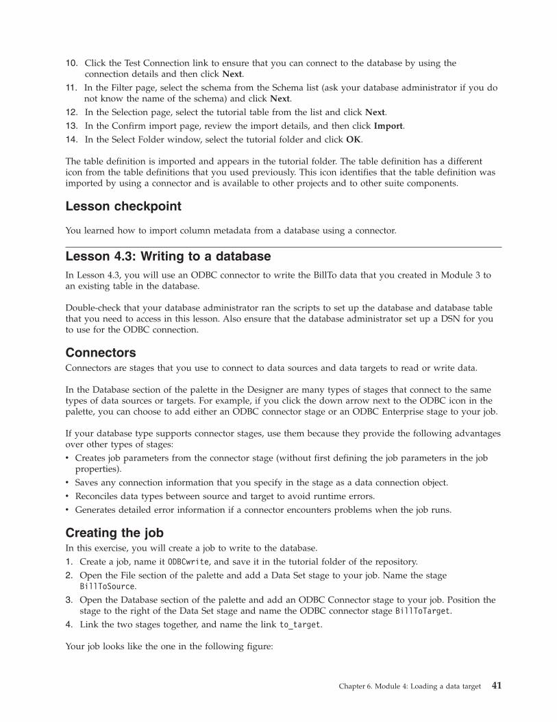
10. Click the Test Connection link to ensure that you can connect to the database by using the
connection details and then click Next.
11. In the Filter page, select the schema from the Schema list (ask your database administrator if you do
not know the name of the schema) and click Next.
12. In the Selection page, select the tutorial table from the list and click Next.
13. In the Confirm import page, review the import details, and then click Import.
14. In the Select Folder window, select the tutorial folder and click OK.
The table definition is imported and appears in the tutorial folder. The table definition has a different
icon from the table definitions that you used previously. This icon identifies that the table definition was
imported by using a connector and is available to other projects and to other suite components.
Lesson checkpoint
You learned how to import column metadata from a database using a connector.
Lesson 4.3: Writing to a database
In Lesson 4.3, you will use an ODBC connector to write the BillTo data that you created in Module 3 to
an existing table in the database.
Double-check that your database administrator ran the scripts to set up the database and database table
that you need to access in this lesson. Also ensure that the database administrator set up a DSN for you
to use for the ODBC connection.
Connectors
Connectors are stages that you use to connect to data sources and data targets to read or write data.
In the Database section of the palette in the Designer are many types of stages that connect to the same
types of data sources or targets. For example, if you click the down arrow next to the ODBC icon in the
palette, you can choose to add either an ODBC connector stage or an ODBC Enterprise stage to your job.
If your database type supports connector stages, use them because they provide the following advantages
over other types of stages:
v Creates job parameters from the connector stage (without first defining the job parameters in the job
properties).
v Saves any connection information that you specify in the stage as a data connection object.
v Reconciles data types between source and target to avoid runtime errors.
v Generates detailed error information if a connector encounters problems when the job runs.
Creating the job
In this exercise, you will create a job to write to the database.
1. Create a job, name it ODBCwrite, and save it in the tutorial folder of the repository.
2. Open the File section of the palette and add a Data Set stage to your job. Name the stage
BillToSource.
3. Open the Database section of the palette and add an ODBC Connector stage to your job. Position the
stage to the right of the Data Set stage and name the ODBC connector stage BillToTarget.
4. Link the two stages together, and name the link to_target.
Your job looks like the one in the following figure:
Chapter 6. Module 4: Loading a data target 41
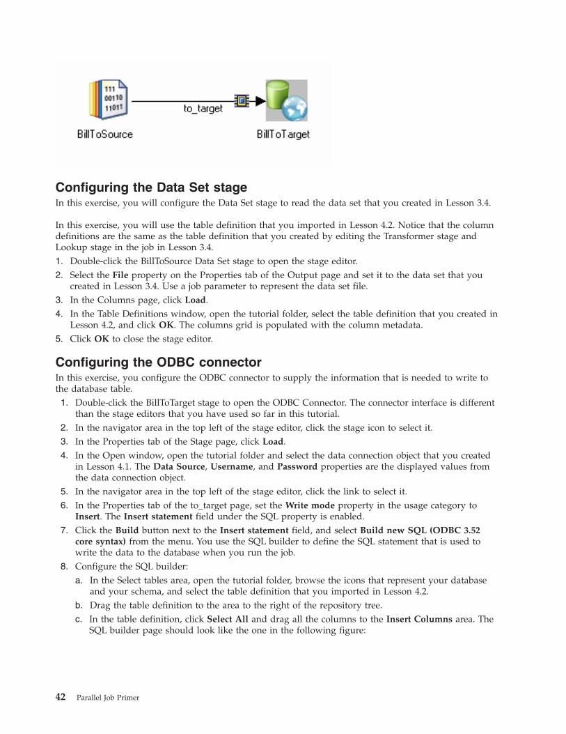
Configuring the Data Set stage
In this exercise, you will configure the Data Set stage to read the data set that you created in Lesson 3.4.
In this exercise, you will use the table definition that you imported in Lesson 4.2. Notice that the column
definitions are the same as the table definition that you created by editing the Transformer stage and
Lookup stage in the job in Lesson 3.4.
1. Double-click the BillToSource Data Set stage to open the stage editor.
2. Select the File property on the Properties tab of the Output page and set it to the data set that you
created in Lesson 3.4. Use a job parameter to represent the data set file.
3. In the Columns page, click Load.
4. In the Table Definitions window, open the tutorial folder, select the table definition that you created in
Lesson 4.2, and click OK. The columns grid is populated with the column metadata.
5. Click OK to close the stage editor.
Configuring the ODBC connector
In this exercise, you configure the ODBC connector to supply the information that is needed to write to
the database table.
1. Double-click the BillToTarget stage to open the ODBC Connector. The connector interface is different
than the stage editors that you have used so far in this tutorial.
2. In the navigator area in the top left of the stage editor, click the stage icon to select it.
3. In the Properties tab of the Stage page, click Load.
4. In the Open window, open the tutorial folder and select the data connection object that you created
in Lesson 4.1. The Data Source, Username, and Password properties are the displayed values from
the data connection object.
5. In the navigator area in the top left of the stage editor, click the link to select it.
6. In the Properties tab of the to_target page, set the Write mode property in the usage category to
Insert. The Insert statement field under the SQL property is enabled.
7. Click the Build button next to the Insert statement field, and select Build new SQL (ODBC 3.52
core syntax) from the menu. You use the SQL builder to define the SQL statement that is used to
write the data to the database when you run the job.
8. Configure the SQL builder:
a. In the Select tables area, open the tutorial folder, browse the icons that represent your database
and your schema, and select the table definition that you imported in Lesson 4.2.
b. Drag the table definition to the area to the right of the repository tree.
c. In the table definition, click Select All and drag all the columns to the Insert Columns area. The
SQL builder page should look like the one in the following figure:
42 Parallel Job Primer
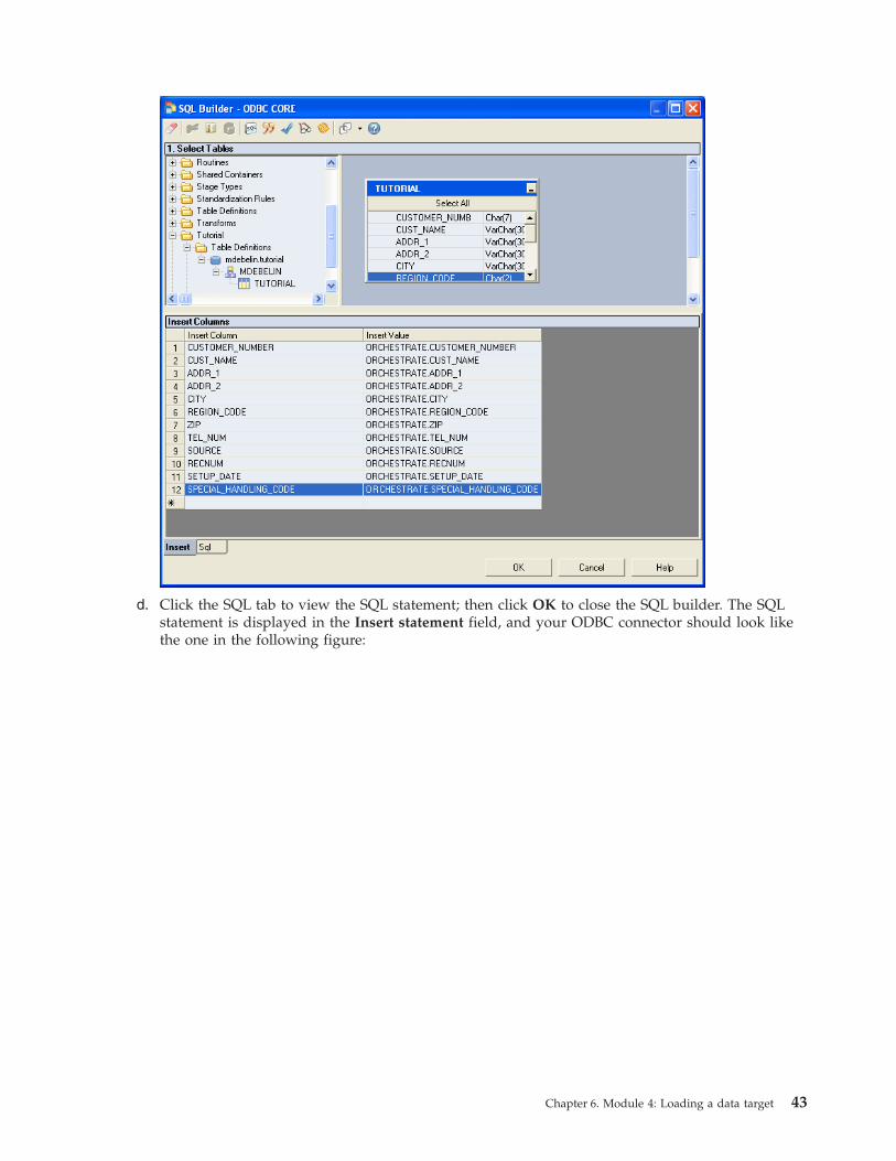
d. Click the SQL tab to view the SQL statement; then click OK to close the SQL builder. The SQL
statement is displayed in the Insert statement field, and your ODBC connector should look like
the one in the following figure:
Chapter 6. Module 4: Loading a data target 43
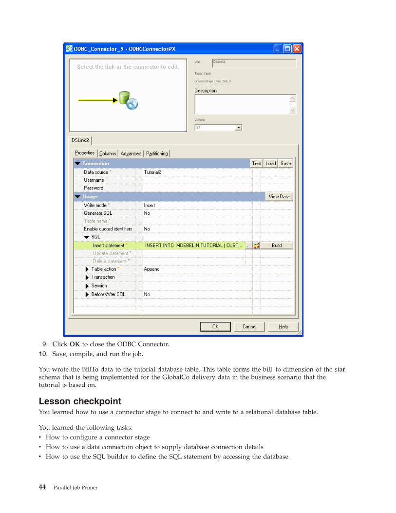
9. Click OK to close the ODBC Connector.
10. Save, compile, and run the job.
You wrote the BillTo data to the tutorial database table. This table forms the bill_to dimension of the star
schema that is being implemented for the GlobalCo delivery data in the business scenario that the
tutorial is based on.
Lesson checkpoint
You learned how to use a connector stage to connect to and write to a relational database table.
You learned the following tasks:
v How to configure a connector stage
v How to use a data connection object to supply database connection details
v How to use the SQL builder to define the SQL statement by accessing the database.
44 Parallel Job Primer
Module 4 summary
In this module, you designed a job that writes data to a table in a relational database.
In lesson 4.1, you learned how to define a data connection object; in lesson 4.2, you imported column
metadata from a data base; and in lesson 4.3, you learned how to write data to a relational data base
target.
Lessons learned
By completing this module, you learned about the following concepts and tasks:
v Load data into data targets
v Use the Designer clients reusable components
Chapter 6. Module 4: Loading a data target 45

46 Parallel Job Primer
Chapter 7. Module 5: Processing in parallel
Parallel jobs are scalable and can speed the processing of data by spreading the load over multiple
processors.
When you design parallel jobs in the Designer client, you concentrate on designing your jobs to run
sequentially, unconcerned about how parallel processing is implemented. You specify the logic of the job,
and WebSphere DataStage specifies the best implementation on the available hardware. However, you
can exert more exact control on job implementation.
In this module, you learn about how you can control whether jobs run sequentially or in parallel, and
you look at the partitioning of data.
Learning objectives
After completing the lessons in this module, you will know how to do the following:
v How to use the configuration file to optimize parallel processing.
v How to control parallel processing at the stage level in your job design.
v How to control the partitioning of data so that it can be handled by multiple processors.
This module should take approximately 60 minutes to complete.
Prerequisites
You must be working on a computer with multiple processors.
You must have DataStage administrator privileges to create and use a new configuration file.
Lesson 5.1: Exploring the configuration file
In this lesson, the configuration file is the key to getting the optimum performance from the jobs that you
design.
The shape and size of the computer system on which you run jobs is defined in the configuration file.
When you run a job, the parallel engine organizes the resources that the job needs according to what is
defined in the configuration file. When your computer system changes, you change the configuration file,
not the jobs.
Unless you specify otherwise, the parallel engine uses a default configuration file that is set up when
WebSphere DataStage is installed.
Opening the default configuration file
You use the Configurations editor in the Designer client to view the default configuration file.
To open the default configuration file:
1. Select Tools → Configurations.
2. In the Configuration window, select default from the list. The contents of the default configuration file
are displayed.
Example configuration file
The following example shows a default configuration file from a four-processor SMP computer system.
© Copyright IBM Corp. 2006 47
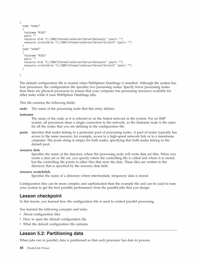
{
node "node1"
{
fastname "R101"
pools ""
resource disk "C:/IBM/InformationServer/Server/Datasets" {pools ""}
resource scratchdisk "C:/IBM/InformationServer/Server/Scratch" {pools ""}
}
node "node2"
{
fastname "R101"
pools ""
resource disk "C:/IBM/InformationServer/Server/Datasets" {pools ""}
resource scratchdisk "C:/IBM/InformationServer/Server/Scratch" {pools ""}
}
}
The default configuration file is created when WebSphere DataStage is installed. Although the system has
four processors, the configuration file specifies two processing nodes. Specify fewer processing nodes
than there are physical processors to ensure that your computer has processing resources available for
other tasks while it runs WebSphere DataStage jobs.
This file contains the following fields:
node The name of the processing node that this entry defines.
fastname
The name of the node as it is referred to on the fastest network in the system. For an SMP
system, all processors share a single connection to the network, so the fastname node is the same
for all the nodes that you are defining in the configuration file.
pools Specifies that nodes belong to a particular pool of processing nodes. A pool of nodes typically has
access to the same resource, for example, access to a high-speed network link or to a mainframe
computer. The pools string is empty for both nodes, specifying that both nodes belong to the
default pool.
resource disk
Specifies the name of the directory where the processing node will write data set files. When you
create a data set or file set, you specify where the controlling file is called and where it is stored,
but the controlling file points to other files that store the data. These files are written to the
directory that is specified by the resource disk field.
resource scratchdisk
Specifies the name of a directory where intermediate, temporary data is stored.
Configuration files can be more complex and sophisticated than the example file and can be used to tune
your system to get the best possible performance from the parallel jobs that you design.
Lesson checkpoint
In this lesson, you learned how the configuration file is used to control parallel processing.
You learned the following concepts and tasks:
v About configuration files
v How to open the default configuration file
v What the default configuration file contains
Lesson 5.2: Partitioning data
When jobs run in parallel, data is partitioned so that each processor has data to process.
48 Parallel Job Primer
In the simplest scenario, do not worry about how your data is partitioned. WebSphere DataStage can
partition your data and implement the most efficient partitioning method.
Most partitioning operations result in a set of partitions that are as near to equal size as possible,
ensuring an even load across your processors.
As you perform other operations, you need to control partitioning to ensure that you get consistent
results. For example, you are using an aggregator stage to summarize your data to get the answers that
you need. You must ensure that related data is grouped together in the same partition before the
summary operation is performed on that partition.
In this lesson, you will run the sample job that you ran in Lesson 1. By default, the data that is read from
the file is not partitioned when it is written to the data set. You change the job so that it has the same
number of partitions as there are nodes defined in your system’s default configuration file.
Viewing partitions in a data set
You need to be able to see how data in a data set is divided into partitions to determine how the data is
being processed.
This exercise teaches you how to use the data set management tool to look at data sets and how they are
structured.
To see how data sets are structured:
1. Select Tools → Data Set Management.
2. In the Select from server window, browse for the data set file that was written by the
GlobalCo_BillTo.ds sample job in Module 1 and click OK.
3. In the partitions section, the data was written to a single partition. The Data Set Management window
should look like the one in the following figure:
Chapter 7. Module 5: Processing in parallel 49
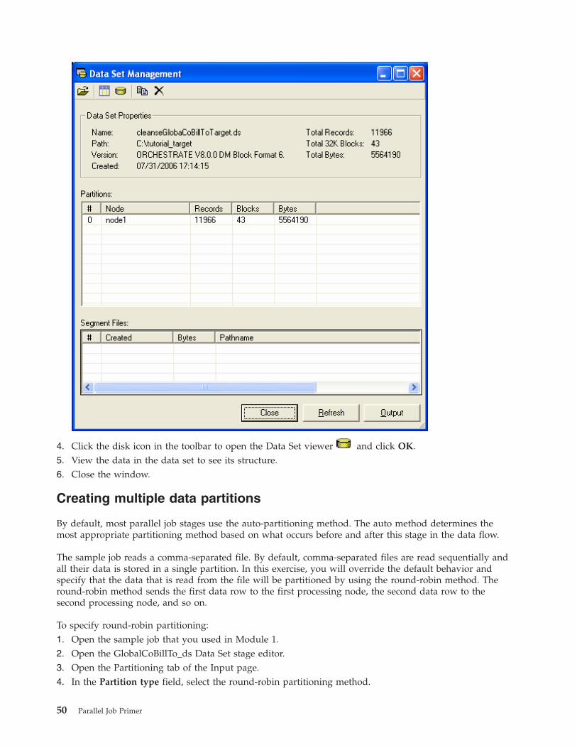
4. Click the disk icon in the toolbar to open the Data Set viewer
and click OK.
5. View the data in the data set to see its structure.
6. Close the window.
Creating multiple data partitions
By default, most parallel job stages use the auto-partitioning method. The auto method determines the
most appropriate partitioning method based on what occurs before and after this stage in the data flow.
The sample job reads a comma-separated file. By default, comma-separated files are read sequentially and
all their data is stored in a single partition. In this exercise, you will override the default behavior and
specify that the data that is read from the file will be partitioned by using the round-robin method. The
round-robin method sends the first data row to the first processing node, the second data row to the
second processing node, and so on.
To specify round-robin partitioning:
1. Open the sample job that you used in Module 1.
2. Open the GlobalCoBillTo_ds Data Set stage editor.
3. Open the Partitioning tab of the Input page.
4. In the Partition type field, select the round-robin partitioning method.
50 Parallel Job Primer
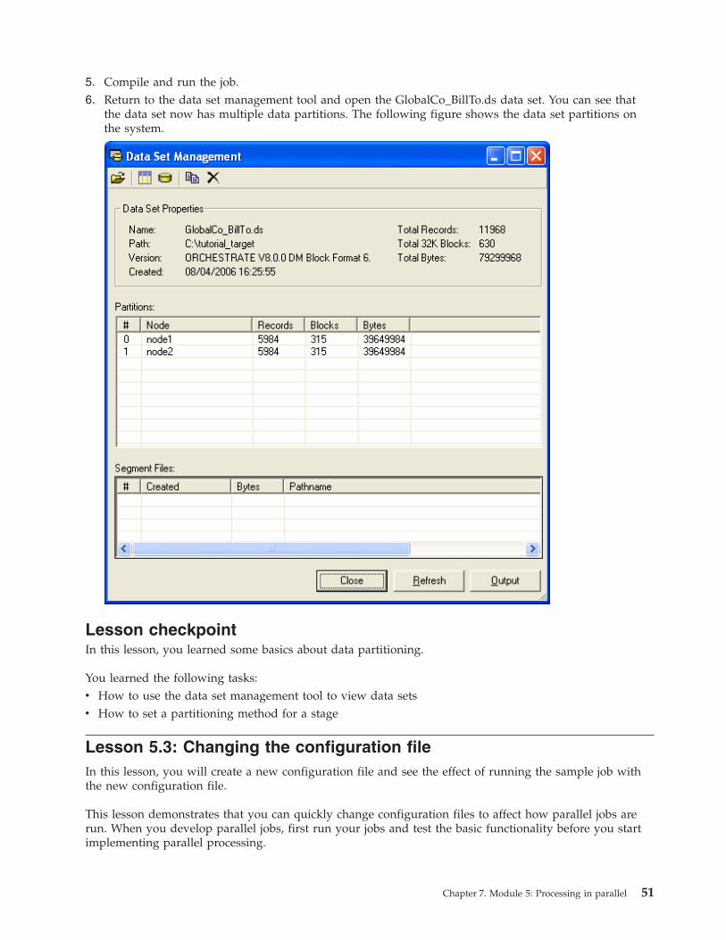
5. Compile and run the job.
6. Return to the data set management tool and open the GlobalCo_BillTo.ds data set. You can see that
the data set now has multiple data partitions. The following figure shows the data set partitions on
the system.
Lesson checkpoint
In this lesson, you learned some basics about data partitioning.
You learned the following tasks:
v How to use the data set management tool to view data sets
v How to set a partitioning method for a stage
Lesson 5.3: Changing the configuration file
In this lesson, you will create a new configuration file and see the effect of running the sample job with
the new configuration file.
This lesson demonstrates that you can quickly change configuration files to affect how parallel jobs are
run. When you develop parallel jobs, first run your jobs and test the basic functionality before you start
implementing parallel processing.
Chapter 7. Module 5: Processing in parallel 51
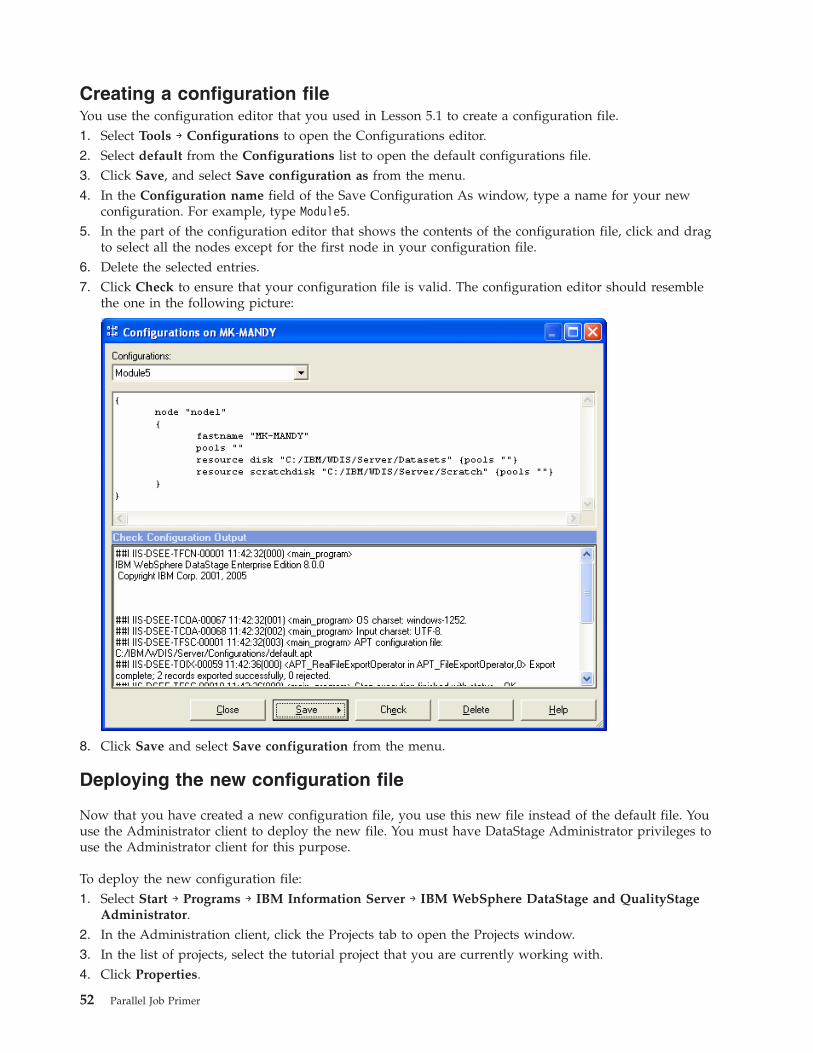
Creating a configuration file
You use the configuration editor that you used in Lesson 5.1 to create a configuration file.
1. Select Tools → Configurations to open the Configurations editor.
2. Select default from the Configurations list to open the default configurations file.
3. Click Save, and select Save configuration as from the menu.
4. In the Configuration name field of the Save Configuration As window, type a name for your new
configuration. For example, type Module5.
5. In the part of the configuration editor that shows the contents of the configuration file, click and drag
to select all the nodes except for the first node in your configuration file.
6. Delete the selected entries.
7. Click Check to ensure that your configuration file is valid. The configuration editor should resemble
the one in the following picture:
8. Click Save and select Save configuration from the menu.
Deploying the new configuration file
Now that you have created a new configuration file, you use this new file instead of the default file. You
use the Administrator client to deploy the new file. You must have DataStage Administrator privileges to
use the Administrator client for this purpose.
To deploy the new configuration file:
1. Select Start → Programs → IBM Information Server → IBM WebSphere DataStage and QualityStage
Administrator.
2. In the Administration client, click the Projects tab to open the Projects window.
3. In the list of projects, select the tutorial project that you are currently working with.
4. Click Properties.
52 Parallel Job Primer
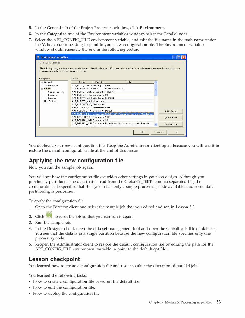
5. In the General tab of the Project Properties window, click Environment.
6. In the Categories tree of the Environment variables window, select the Parallel node.
7. Select the APT_CONFIG_FILE environment variable, and edit the file name in the path name under
the Value column heading to point to your new configuration file. The Environment variables
window should resemble the one in the following picture:
You deployed your new configuration file. Keep the Administrator client open, because you will use it to
restore the default configuration file at the end of this lesson.
Applying the new configuration file
Now you run the sample job again.
You will see how the configuration file overrides other settings in your job design. Although you
previously partitioned the data that is read from the GlobalCo_BillTo comma-separated file, the
configuration file specifies that the system has only a single processing node available, and so no data
partitioning is performed.
To apply the configuration file:
1. Open the Director client and select the sample job that you edited and ran in Lesson 5.2.
2. Click
to reset the job so that you can run it again.
3. Run the sample job.
4. In the Designer client, open the data set management tool and open the GlobalCo_BillTo.ds data set.
You see that the data is in a single partition because the new configuration file specifies only one
processing node.
5. Reopen the Administrator client to restore the default configuration file by editing the path for the
APT_CONFIG_FILE environment variable to point to the default.apt file.
Lesson checkpoint
You learned how to create a configuration file and use it to alter the operation of parallel jobs.
You learned the following tasks:
v How to create a configuration file based on the default file.
v How to edit the configuration file.
v How to deploy the configuration file
Chapter 7. Module 5: Processing in parallel 53
Module 5 summary
In this module, you learned how to use the configuration file to control how your parallel jobs are run.
You also learned how to control the partitioning of data at the level of individual stages.
Lessons learned
By completing this module, you learned about the following concepts and tasks:
v The configuration file
v How to use the configuration editor to edit the configuration file
v How to control data
54 Parallel Job Primer
Chapter 8. Tutorial summary
You completed your part of the GlobalCo/WorldCo merger project, and in doing so learned about basic
parallel job design skills.
Now that you have successfully completed the WebSphere DataStage tutorial, you can complete the IBM
WebSphere QualityStage tutorial. The WebSphere QualityStage tutorial implements the standardization of
customer information and the removal of duplicate entries from the data.
Lessons learned
By completing this tutorial, you learned about the following concepts and tasks:
v How to extract, transform, and load data by using WebSphere DataStage
v Using the parallel processing power of WebSphere DataStage.
v How to reuse the job design elements
© Copyright IBM Corp. 2006 55

56 Parallel Job Primer
Appendix. Installing and setting up the tutorial
Before you can start the tutorial, you need to install some files and perform some setup tasks.
You need DataStage administrator privileges and Windows administrator privileges to perform some of
the installation and setup tasks. You need a higher level of system knowledge and database knowledge to
complete the installation and setup tasks than you need to complete the tutorial.
To install and set up the tutorial, complete the following tasks:
1. “Creating a folder for the tutorial files”
2. “Creating the tutorial project”
3. “Copying the data files to the project folder or directory”
4. “Importing the tutorial components into the tutorial project” on page 58
5. “Creating a target database table” on page 58
6. One of the following tasks:
v “Creating a DSN for the tutorial table on a Windows computer” on page 59
v “Creating a DSN for the tutorial table on a UNIX or Linux computer” on page 59
Creating a folder for the tutorial files
Create a folder on your WebSphere DataStage client computer and copy the files from the installation CD
to the folder.
1. Insert the CD into the CD drive or DVD drive of the client computer.
2. Create a new folder on your computer (for example, C:\tutorial).
3. Copy the folder on the CD named \TutorialData\DataStage\parallel_tutorial to the folder that you
created on the client computer.
Creating the tutorial project
Create a new project for the tutorial to keep the tutorial exercises separate from other work on
WebSphere DataStage.
You must have DataStage Administrator privileges.
1. Select Start → Programs → IBM Information Server → IBM WebSphere DataStage and QualityStage
Administrator
2. In the Attach window, type your user name and password.
3. In the Administrator client window, click the Projects tab.
4. In the Projects page, click Add.
5. In the Name field, specify the name of the new project (for example, Tutorial)
6. Click OK.
7. Click Close to close the Administrator client.
The new project is created.
Copying the data files to the project folder or directory
Copy the tutorial data files from the tutorial folder on the client computer to the project folder or
directory on the WebSphere DataStage server computer.
© Copyright IBM Corp. 2006 57
The WebSphere DataStage server might be on the same Windows computer as the clients, or it might be
on a separate Windows, UNIX, or Linux computer. When you created the project for the tutorial, you
automatically created a folder or directory for that project on the server computer.
1. Open the tutorial folder that you created on the client computer and locate all the files that end with
.csv:
v CustomerCountry.csv
v SpecialHandling.csv
v GlobalCo_BillTo.csv2. Open the project folder on the server computer for the tutorial project that you created. The default
path name for a Windows server is c:\IBM\InformationServer\Server\Projects\tutorial_project. The
default path name for a UNIX or Linux server is /opt/IBM/InformationServer/Server/Projects/tutorial_project.
3. Copy the files from the tutorial folder on the client computer to the project folder on the server
computer.
Importing the tutorial components into the tutorial project
Use the Designer client to import the sample job and sample table definition into the tutorial.
1. Select Start → Programs → IBM Information Server → IBM WebSphere DataStage and QualityStage
Designer.
2. In the Attach window, type your user name and password.
3. Select the tutorial project from the Project list and then click OK. The Designer client opens and
displays the New window.
4. Click Cancel to close the New window because you are opening an existing job and not creating a
new job or other object.
5. Select Import → DataStage Components.
6. In the Import from file field of the DataStage Repository Import window, type tutorial_folder\parallel_tutorial.dsx. tutorial_folder is the name of the tutorial folder that you created on the client
computer.
7. Select the Import all option.
8. Click OK. The Designer client imports the sample job and sample table definition into a repository
folder named tutorial.
9. Select File → Exit to close the Designer client.
Creating a target database table
Create a table in the relational database that hosts the dynamic repository for WebSphere DataStage.
Module 4 of the tutorial imports metadata from a table in a relational database and then writes data to
the table. WebSphere DataStage uses a repository that is hosted by a relational database (DB2 by default)
and you can create the table in that database. There are data definition language (DDL) scripts for DB2,
Oracle, and SQL Server in the tutorial folder. To create the table:
1. Open the administrator client for your database (for example, the DB2 Control Center).
2. Create a new database named Tutorial.
3. Connect to the new database.
4. Run the appropriate DDL script to create the tutorial table in the new database. The scripts are in the
tutorial folder and are named as follows:
v DB2_table.ddl
v Oracle_table.ddl
v SQLserver_table.ddl
58 Parallel Job Primer
5. Close the database administrator client.
Creating a DSN for the tutorial table on a Windows computer
Create a DSN for the database table so that users of the tutorial can connect to the table by using an
ODBC connection.
You define the DSN on the computer where the WebSphere DataStage server is installed. The procedure
on a Windows computer is different from the procedure on a UNIX or Linux computer. You require
administrator privileges on the Windows computer.
To set up a DSN on a Windows computer:
1. Open the control panel and select Administrative Tools.
2. Select Data Sources (ODBC).
3. Select the System DSN tab.
4. In the System DSN page, click Add.
5. In the Create New Data Source window, select a driver for the database. A window opens that is
specific to the driver that you selected.
6. Specify the details that the driver requires to connect to the tutorial database. If you specified a user
name and password for the database, then the connection details include user name and password.
Creating a DSN for the tutorial table on a UNIX or Linux computer
Create a DSN for the database table so that users of the tutorial can connect to the table by using an
ODBC connection.
You define the DSN on the computer where the WebSphere DataStage server is installed. The procedure
on a UNIX or Linux computer is different from the procedure on a Windows computer. To set up a DSN
on a UNIX or Linux computer, you edit three files:
v dsenv
v odbc.ini
v uvodbc.config
The entries that you make in each file depend on the type of database. Full details are in the IBM
Information Server Planning, Configuration, and Installation Guide.
Appendix. Installing and setting up the tutorial 59

60 Parallel Job Primer
Accessing information about IBM
IBM has several methods for you to learn about products and services.
You can find the latest information on the Web at www.ibm.com/software/data/integration/info_server/:
v Product documentation in PDF and online information centers
v Product downloads and fix packs
v Release notes and other support documentation
v Web resources, such as white papers and IBM Redbooks™
v Newsgroups and user groups
v Book orders
To access product documentation, go to this site:
publib.boulder.ibm.com/infocenter/iisinfsv/v8r0/index.jsp
You can order IBM publications online or through your local IBM representative.
v To order publications online, go to the IBM Publications Center at www.ibm.com/shop/publications/order.
v To order publications by telephone in the United States, call 1-800-879-2755.
To find your local IBM representative, go to the IBM Directory of Worldwide Contacts at
www.ibm.com/planetwide.
Contacting IBM
You can contact IBM by telephone for customer support, software services, and general information.
Customer support
To contact IBM customer service in the United States or Canada, call 1-800-IBM-SERV (1-800-426-7378).
Software services
To learn about available service options, call one of the following numbers:
v In the United States: 1-888-426-4343
v In Canada: 1-800-465-9600
General information
To find general information in the United States, call 1-800-IBM-CALL (1-800-426-2255).
Go to www.ibm.com for a list of numbers outside of the United States.
Accessible documentation
Documentation is provided in XHTML format, which is viewable in most Web browsers.
© Copyright IBM Corp. 2006 61
XHTML allows you to view documentation according to the display preferences that you set in your
browser. It also allows you to use screen readers and other assistive technologies.
Syntax diagrams are provided in dotted decimal format. This format is available only if you are accessing
the online documentation using a screen reader.
Providing comments on the documentation
Please send any comments that you have about this information or other documentation.
Your feedback helps IBM to provide quality information. You can use any of the following methods to
provide comments:
v Send your comments using the online readers’ comment form at www.ibm.com/software/awdtools/rcf/.
v Send your comments by e-mail to [email protected]. Include the name of the product, the version
number of the product, and the name and part number of the information (if applicable). If you are
commenting on specific text, please include the location of the text (for example, a title, a table number,
or a page number).
62 Parallel Job Primer
Notices and trademarks
Notices
This information was developed for products and services offered in the U.S.A.
IBM may not offer the products, services, or features discussed in this document in other countries.
Consult your local IBM representative for information on the products and services currently available in
your area. Any reference to an IBM product, program, or service is not intended to state or imply that
only that IBM product, program, or service may be used. Any functionally equivalent product, program,
or service that does not infringe any IBM intellectual property right may be used instead. However, it is
the user’s responsibility to evaluate and verify the operation of any non-IBM product, program, or
service.
IBM may have patents or pending patent applications covering subject matter described in this
document. The furnishing of this document does not grant you any license to these patents. You can send
license inquiries, in writing, to:
IBM Director of Licensing
IBM Corporation
North Castle Drive
Armonk, NY 10504-1785 U.S.A.
For license inquiries regarding double-byte (DBCS) information, contact the IBM Intellectual Property
Department in your country or send inquiries, in writing, to:
IBM World Trade Asia Corporation
Licensing 2-31 Roppongi 3-chome, Minato-ku
Tokyo 106-0032, Japan
The following paragraph does not apply to the United Kingdom or any other country where such
provisions are inconsistent with local law: INTERNATIONAL BUSINESS MACHINES CORPORATION
PROVIDES THIS PUBLICATION ″AS IS″ WITHOUT WARRANTY OF ANY KIND, EITHER EXPRESS OR
IMPLIED, INCLUDING, BUT NOT LIMITED TO, THE IMPLIED WARRANTIES OF
NON-INFRINGEMENT, MERCHANTABILITY OR FITNESS FOR A PARTICULAR PURPOSE. Some
states do not allow disclaimer of express or implied warranties in certain transactions, therefore, this
statement may not apply to you.
This information could include technical inaccuracies or typographical errors. Changes are periodically
made to the information herein; these changes will be incorporated in new editions of the publication.
IBM may make improvements and/or changes in the product(s) and/or the program(s) described in this
publication at any time without notice.
Any references in this information to non-IBM Web sites are provided for convenience only and do not in
any manner serve as an endorsement of those Web sites. The materials at those Web sites are not part of
the materials for this IBM product and use of those Web sites is at your own risk.
IBM may use or distribute any of the information you supply in any way it believes appropriate without
incurring any obligation to you.
© Copyright IBM Corp. 2006 63
Licensees of this program who wish to have information about it for the purpose of enabling: (i) the
exchange of information between independently created programs and other programs (including this
one) and (ii) the mutual use of the information which has been exchanged, should contact:
IBM Corporation
J46A/G4
555 Bailey Avenue
San Jose, CA 95141-1003 U.S.A.
Such information may be available, subject to appropriate terms and conditions, including in some cases,
payment of a fee.
The licensed program described in this document and all licensed material available for it are provided
by IBM under terms of the IBM Customer Agreement, IBM International Program License Agreement or
any equivalent agreement between us.
Any performance data contained herein was determined in a controlled environment. Therefore, the
results obtained in other operating environments may vary significantly. Some measurements may have
been made on development-level systems and there is no guarantee that these measurements will be the
same on generally available systems. Furthermore, some measurements may have been estimated through
extrapolation. Actual results may vary. Users of this document should verify the applicable data for their
specific environment.
Information concerning non-IBM products was obtained from the suppliers of those products, their
published announcements or other publicly available sources. IBM has not tested those products and
cannot confirm the accuracy of performance, compatibility or any other claims related to non-IBM
products. Questions on the capabilities of non-IBM products should be addressed to the suppliers of
those products.
All statements regarding IBM’s future direction or intent are subject to change or withdrawal without
notice, and represent goals and objectives only.
This information is for planning purposes only. The information herein is subject to change before the
products described become available.
This information contains examples of data and reports used in daily business operations. To illustrate
them as completely as possible, the examples include the names of individuals, companies, brands, and
products. All of these names are fictitious and any similarity to the names and addresses used by an
actual business enterprise is entirely coincidental.
COPYRIGHT LICENSE:
This information contains sample application programs in source language, which illustrate programming
techniques on various operating platforms. You may copy, modify, and distribute these sample programs
in any form without payment to IBM, for the purposes of developing, using, marketing or distributing
application programs conforming to the application programming interface for the operating platform for
which the sample programs are written. These examples have not been thoroughly tested under all
conditions. IBM, therefore, cannot guarantee or imply reliability, serviceability, or function of these
programs.
Each copy or any portion of these sample programs or any derivative work, must include a copyright
notice as follows:
© (your company name) (year). Portions of this code are derived from IBM Corp. Sample Programs. ©
Copyright IBM Corp. _enter the year or years_. All rights reserved.
64 Parallel Job Primer

If you are viewing this information softcopy, the photographs and color illustrations may not appear.
Trademarks
IBM trademarks and certain non-IBM trademarks are marked at their first occurrence in this document.
See http://www.ibm.com/legal/copytrade.shtml for information about IBM trademarks.
The following terms are trademarks or registered trademarks of other companies:
Java™ and all Java-based trademarks and logos are trademarks or registered trademarks of Sun
Microsystems, Inc. in the United States, other countries, or both.
Microsoft®, Windows, Windows NT®, and the Windows logo are trademarks of Microsoft Corporation in
the United States, other countries, or both.
Intel®, Intel Inside® (logos), MMX and Pentium® are trademarks of Intel Corporation in the United States,
other countries, or both.
UNIX is a registered trademark of The Open Group in the United States and other countries.
Linux is a trademark of Linus Torvalds in the United States, other countries, or both.
Other company, product or service names might be trademarks or service marks of others.
Notices and trademarks 65

66 Parallel Job Primer
Index
Aaccessibility 62
addingjob parameters 20
adding stages 14
Administrator client 57
starting 52
Ccolumn metadata
importing 18, 40
loading 18
comma-separated files 58
comments on documentation 62
compiling jobs 9
configuration file 47, 51
default 47
configurations viewer 47, 52
connectorODBC 40
configuring 42
contacting IBM 61
creatingjob parameters 22
creating a job 13
Ddata
combining 29
looking up 29
partitioning 49
reject 32
stageLookup 29
data browser 11
data connectioncreating 39
data files 58
data set management tool 49
Data Set stage 8
database 58
Designer client 5, 58
starting 6
Director clientstarting 9
documentationaccessible 62
ordering 61
Web site 61
DSN 59
Eenvironment variables 53
Ffiles
data 58
folder 57
Iimporting
column metadata 18, 40
tutorial components 58
installing 57
Jjob parameters
adding 20
parameter sets 22
job properties 20
jobscompiling 9
creating 13
opening 5
running 9
Llegal notices 63
loadingcolumn metadata 18
lookup 29
Lookup File Set stage 17, 30
Lookup stage 29
Mmetadata
importing 18, 40
loading 18
OODBC 40, 42, 59
opening a job 5
Pparameter set
creating 22
parameter sets 22
partitioning data 49
partitionscreating 50
projectcreating 57
propertiesjob 20
stage 15
Rreaders’ comment form 62
reject data 32
relational database 58
repository 5
repository objectsdata connections 39
parameter set 22
table definition 18, 40
running jobs 9
Ssample job 5
screen readers 62
Sequential File stage 8
setting up 57
source data files 58
SQL Builder 42
stageLookup File Set 17, 30
Transformer 26
stage properties 15
stagesadding 14
starting the Designer client 6
Ttable definition 18, 40
trademarks 65
Transformer stage 26
tutorialfolder 57
Vviewing data 11
© Copyright IBM Corp. 2006 67

68 Parallel Job Primer


����
Printed in USA
SC18-9889-00