data'communications · pdf filedata'communications over aircraft power ......
TRANSCRIPT

AFFTC-PA-05139
DATA'COMMUNICATIONS OVERAIRCRAFT POWER LINES
Hai TianTom Trojak
Charles Jones PhD
F AIR FORCE FLIGHT TEST CENTEREDWARDS AFB, CAF
JUNE 2005TC
Approved for public release: distribution is unlimited.
AIR FORCE FLIGHT TEST CENTEREDWARDS AIR FORCE BASE, CALIFORNIA
AIR FORCE MATERIEL COMMAND, UNITED STATES AIR FORCE

Form ApprovedREPORT DOCUMENTATION PAGE OMB No. 0704-0188
Public reporting burden for this collection of information is estimated to average 1 hour per response, including the time for reviewing instructions, searching existing data sources, gathering and maintaining thedata needed, and completing and reviewing this collection of information. Send comments regarding this burden estimate or any other aspect of this collection of information, including suggestions for reducingthis burden to Department of Defense, Washington Headquarters Services, Directorate for Information Operations and Reports (0704-0188), 1215 Jefferson Davis Highway, Suite 1204, Arlington, VA 22202-4302. Respondents should be aware that notwithstanding any other provision of law, no person shall be subject to any penalty for failing to comply with a collection of information if it does not display a currentlyvalid OMB control number. PLEASE DO NOT RETURN YOUR FORM TO THE ABOVE ADDRESS.
1. REPORT DATE (DD-MM-YYYY) 2. REPORT TYPE 3. DATES COVERED (From - To)
28-06-2005 Technical Paper4. TITLE AND SUBTITLE 5a. CONTRACT NUMBER
Data Communications Over Aircraft Power Lines
5b. GRANT NUMBER
5c. PROGRAM ELEMENT NUMBER
6. AUTHOR(S) 5d. PROJECT NUMBER
Hai Tian 5e. TASK NUMBERTom Trojak
Charles H. Jones 5f. WORK UNIT NUMBER
7. PERFORMING ORGANIZATION NAME(S) AND ADDRESS(ES) 8. PERFORMING ORGANIZATION REPORT
Air Force Flight Test Center NUMBER
Edwards AFB, CA 93524 AFFTC-PA-05 139
9. SPONSORING / MONITORING AGENCY NAME(S) AND ADDRESS(ES) 10. SPONSOR/MONITOR'S ACRONYM(S)
412TW/ENTIAir Force Flight Test Center 11. SPONSOR/MONITOR'S REPORT
Edwards AFB, CA 93524 NUMBER(S)
12. DISTRIBUTION / AVAILABILITY STATEMENT
A Approved for public release; distribution is unlimited.
13. SUPPLEMENTARY NOTES
CC: 012100 CA: Air Force Flight Test Center Edwards AFB
14. ABSTRACT
This paper introduces a study of the feasibility and initial hardware design for transmitting data over aircraft power lines. The intent of thisdesign is to significantly reduce the wiring in the aircraft instrumentation system. The potential usages of this technology include CommonAirborne Instrumentation System (CAIS) or clock distribution. Aircraft power lines channel characteristics are presented and OrthogonalFrequency Division Multiplexing (OFDM) is introduced as an attractive modulation scheme for high-speed power line transmission. A designof a full-duplex transceiver with accurate frequency planning iý then discussed. A general discussion of what communications protocols areappropriate for this technology is also provided.
15. SUBJECT TERMSFlight Test Instrumentation, Airborne Instrumentation, High-Speed Data Transmissions, Power Line Communications, OFDM, FullDuplex, FDD16. SECURITY CLASSIFICATION OF: 17. LIMITATION 18. NUMBER 19a. NAME OF RESPONSIBLE PERSON
OF ABSTRACT OF PAGES 412 TW/Tech Pubs19b. TELEPHONE NUMBER (include area
a. REPORT b. ABSTRACT c, THIS PAGE Unclassified 10 code)
UNCLASSIFIED UNCLASSIFIED UNCLASSIFIED Unlimited 661-275-9581Standard Form 298 (Rev. 8-98)Prescribed by ANSI Sid. Z39.18
20050705 054
DATA COMMUNICATIONS OVER AIRCRAFT POWER LINES
Hai Tian, Tom TrojakTeletronics Technology Corporation
Charles Jones PhDEdwards Air Force Base
ABSTRACT
This paper introduces a study of the feasibility and initial hardware design for transmitting dataover aircraft power lines. The intent of this design is to significantly reduce the wiring in theaircraft instrumentation system. The potential usages of this technology include Common AirborneInstrumentation System (CAIS) or clock distribution. Aircraft power lines channel characteristicsare presented and Orthogonal Frequency Division Multiplexing (OFDM) is introduced as anattractive modulation scheme for high-speed power line transmission. A design of a full-duplextransceiver with accurate frequency planning is then discussed. A general discussion of whatcommunications protocols are appropriate for this technology is also provided.
KEYWORDS
Flight Test Instrumentation, Airborne Instrumentation, High-Speed -Data Transmissions, PowerLine Communications, OFDM, Full Duplex, FDD
INTRODUCTION
Current instrumentation systems are dependent on installing wires throughout a test vehicleindependent of existing wires on the vehicle. The ability to transfer data over power lines is atechnology that continues to mature. Power line networks already exist throughout most aircraftvehicles. It thus seems appropriate to consider implementing data over power lines for test andevaluation since this could reduce installation costs and schedules significantly. The results inthis paper are from a project specifically targeting data over power line for use with the CommonAirborne Instrumentation System (CAIS) and even more specifically for insertion into airframe,propulsion, and avionics (APA) test and evaluation programs. However, these results can beused to evaluate the practicality of this technology for a larger range of communicationprotocols. For this type of evaluation, there are several areas of technical concern to look at:simplex vs. duplex, time criticality, and maximum bit rate.
The first area of concern is simply whether communication is one-way (simplex) or two-way(duplex). The duplex case might be further broken down into the question of whether the two
1
communications must be at the same time or not. Ethernet, in some sense, is multiplex in thatany two nodes can talk to each other. However, Ethernet's contention-based protocol onlyallows one node to transmit at a time and thus Ethernet is ultimately a half-duplex protocol.Examples of simplex include distributing time or transmission of a data cycle map (often referredto as a PCM matrix). CAIS, on the other hand, is a hard full-duplex protocol that requirescommands and responses to be transmitted simultaneously. This is implemented by havingseparate command and response wires in conventional CAISs.
The second area of concern, time criticality, relates to whether or not data must be at a certainpoint within strict time limitations. Ethernet is not time critical in that packets can be resent orrouted any number of ways; the packets don't even have to arrive in sequence since they can berearranged upon arrival. CAIS, on the other hand, is very time critical. A response must arrivewith a time delay equal to four command words after the command is sent, with a leeway ofabout 600 nanoseconds roundtrip. This leeway exists because of the nondeterministic delayacross different lengths of wire (roughly 1.7 to 2.0 nanoseconds per foot).
Maximum bit rate, the third area, is a concern not only from the point of view of how much datacan be transmitted but also from a protocol point of view. The internet relays data over differentwires that work at different bit rates without a problem. However, each direction of CAIS requires5 Mbps because of the time critical, command and response, nature of the protocol.
The characteristics of the desired physical layer - the aircraft power line - are the driving forcesin the current application. As will be discussed, these characteristics lead to the choice oforthogonal frequency division multiplexing (OFDM) for modulation. Understanding both thecharacteristics of the physical medium and OFDM then allows us to discuss what protocols havepractical applications onthe power line.
AIRCRAFT POWER LINE CHARACTERISTICS
Power lines were not designed as a broadband data transmission medium. They present a harshenvironment for high-frequency signals. Three critical factors of interest are: noise, channeltransfer function (attenuation), and impedance.
According to [1], there are five categories of noise in power lines:
1) Colored background noise with a relatively low power spectral density (PSD). Thistype of time-varying noise can be seen as a summation of all low power noisesources.
2) Narrowband noise consisting of amplitude modulated sinusoidal signals, which iscaused by broadcast stations.
3) Periodic impulsive noise synchronous to the main's frequency with multiple rates.4) Periodic impulsive noise asynchronous to the main's frequency caused by switching
of rectifier diodes of power supplies.
2

5) Asynchronous impulsive noise caused by switching transients in the network. This isthe most harmful noise for data transmission. Its duration varies and the PSD of thenoise may reach 50dB above the background noise.
The Channel Transfer Function is determined by many factors. Multipath is a primary corruptor ofan ideal channel. Multipath due to reflection results in multiple echoes of a signal arriving at areceiver at different times. In a power distribution system, reflections result from lack oftermination, poorly defined line impedance, and the existence of line stubs. Multiple echoes of thesame signal arrive at the receiver at different times. The time spreading in a certain symbol causesintersymbol interference (ISI), which affects the subsequent arriving symbol. As a result, the biterror rate (BER) is increased. In the frequency domain, multipath brings frequency-selectivefading, which randomly affects only a portion of the overall bandwidth at any certain time. Thenotches can be very deep and are unpredictably located. Both the multipath effect and thefrequency-selective fading can vary with time.
Impedance of the power line is determined by devices plugged into the line and the number ofbranches. The time-varying impedance of the power line creates a challenge for the transceiverdesign. Since the impedance of the transceiver has to be fixed, an impedance mismatch betweenthe transceiver and the power line occurs.
In this project, +28V DC power lines, as defined in MIL-STD-704 [6], are used as the transmissionmedium. An initial test of aircraft +28Vdc power line channel characteristics was performed atEdwards AFB, California. The transmission band between 10MHz and 100MHz in the +28Vdcpower lines were tested. Three test points were used in this test (Figure 1 red circles). Two linkswere tested (Figure 1 blue dot lines): Test Link 1 was from the left wing to the right wing, and TestLink 2 was from the left wing to under the cockpit on the right side.
Figure 1 Test Points and Test Links
The electrical power distribution system is a bus structure. Powered devices are grouped byfunction (weapon, navigation, etc.) and each group can be connected and disconnected by asingle switch on a circuit breaker. Wires carry all the electrical power to devices. There are fuseand distribution boxes in the aircraft's central section. Each powered device on the aircraft has itsown 'hot' wire connected to the central boxes. The device's power returns (or grounds) arethrough the aircraft's chassis or frame. This approach with a chassis ground is similar to a car.
This wired bus structure makes high-speed data transmission difficult for at least two reasons.
1. A data transmission path between two devices will see many various-length danglingstubs. Every other device on that particular bus is wired to the single circuit breaker
3

controlling that bus. It is from that common point that power to all other devices onthat bus originates. This is the origin of all the dangling stubs for that bus. Even atmoderate RF frequencies, each stub will look like a short circuit to ground at somefrequency. This causes frequency-selective fading. In Figure 2 and Figure 3, eachnotch in the transfer function is a short circuit to ground from a stub.
2. Since there is no return line, the characteristic impedance of a single line is poorlycontrolled. If the return had a dedicated wire and it ran in proximity to the powerline, characteristic impedance would be at least mildly controlled.
The forward transfer functions from 10 to 100 MHz of Test Link 1 and Test Link 2 are shown inFigure 2 and Figure 3. The low pass channel characteristic can be observed in both figures. Thepremium transmission channel is the frequency band below 20MHz. The frequency band from20MHz to 60MHz has the medium attenuation. High attenuation is observed at the frequencyband higher than 60MHz.
Mar 4 12:46:54
REF 20.0 d8m ATT 30dB A-view 8_wrtl~dB/ NorM NorM _ _e
Ref Level
........ ,alibra on r '
dB/div~Atftnuation
Linear
~~ Units~
Offet
. , ........ outCENTER 50.0 MPHz SPAN 100.0 MHz ,
RBI MHz *VBI* 10 kHz SNIP 50 Ms
Figure 2 Forward Transfer Function of Test Link 1 fromLeft Wing to Right Wing (1OdB/Division)
Ma,- 4 13:47:46REF 20.0 dB. ATT 30d& A_•r•t BMblnk
so. 0 14H2
dE3
_j
E R... ..... .. . . 1..... o. MHZ1-° 1 .. ... .. ... i
." ....... ...... .......
.......... . ' ......... . .;; L ; i k
CENTER SO0. MHz SPAN t 0D.0 MHz:
RBW tI Hz *VMB 10 "hMz SWP SO fft
Figure 3 Forward Transfer Function of Test Link 2 from
Left Wing to Right Side Under Cockpit (5dB/Division)
4

Frequency-selective fading was also observed during the test. The fading creates the deep notches,which are randomly located over the entire frequency band. Some examples are shown in Figure 4,which also shows that some notches have 30dB more attenuation than the average value.
Mar 4 12:59:26 Mar 4 13:00:13 Mar 4 13:01:12REF -3S.0 d~m ATT 10dB A-blnk B.wrt REF -3S.0 dBm ATT 10dB A-blnk: B.wrt REF -35.0 dBm ATT 10dB A-blnk B-wrt
dB/ .... . ...... Norm aorm 2dM Norm Norm 2d6 .. rm or.25/Makm A-.Marker Marker
. .. . . . . -... . . . .. - ..62.500 MHz C EN EI.................. 67.50 0 MHzI - •!•%•• 7 F-S. 333,dB5 62500 . -36.486 dBS 5 0 N. \,,-36.090 dBrn
... . .. .... .... . ......... • • . . . . ...... •. ...... ............. ,. ......... . ..... •,& ..... .......
! ...... .. L . L.. [ .. ....L . .I~ l ! i i i i • • ' _. _L ..• ............... ......: '.,. . .... .. ..... .. ..... ......
S, .... .. ....... . .... ..... . . ..... ... ...... ... .. ..... .......... .. ..... ....... .. .. .. ..,,,CENTER 57.200 MHz SPAN 5.00 MHz CENTER 62.500 MHz SPAN 5.00 MHz CENTER 67.500 MHz SPAN 5.00 MHz
RBW 30 kHz *VBW 10 kHz SwP So ms RBW 30 kHz *VBW 10 kHz SWP 50 ms RBW 30 kHz *VBW 10 kHz SWP SO ms
Figure 4 Example of Frequency Selective Fading on Test Link 1
As in the earlier discussion, time-varying impedance of power line precludes a fixed equalizationapproach. This lack of equalization results in an impedance mismatch and poor return loss. Alarge portion of injected power is reflected back towards the signal source. This effect is shownin Figure 5 as both high attenuation and notches.
Mar 4 13:15:S9:REF -16.8 dBm ATT 10dB A-view 8_.wrt
Ma rker&R E F . ...... . .. ......... • .. ... M HZ.,i {• ca libration cur%* -23.189 d~m
; -J l . , -- . ..... .. . ...................... .... ........... . ,. ,, . . . ..,, , - . .: .... . .
.CENTER 50.0 MHz SPAN 100.0 MHzRBW 1 MHz *VBW 10 kHz SWP 50 MS
Figure 5 Input Return Loss at Left Wing Test Point
ORTHOGONAL FREQUENCY DIVISION MULTIPLEXING (OFDM)
The OFDM is a multicarrier modulation scheme where a transmission band is subdivided into anumber of independent subchannels. These subchannels are carefully spaced such that theirfrequencies are orthogonal to each other. Figure 6 shows such a signal spectrum. Each subcarrieris located on all the other subchannels' spectra zero crossing points. By sampling at thesubchannel's center frequency, spectral orthogonality is maintained.
5
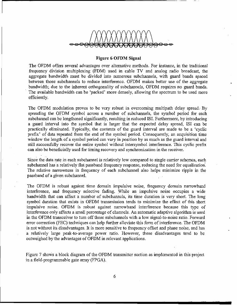
Figure 6 OFDM Signal
The OFDM offers several advantages over alternative methods. For instance, in the traditionalfrequency division multiplexing (FDM) used in cable TV and analog radio broadcast, theaggregate bandwidth must be divided into numerous subchannels, with guard bands spacedbetween those subchannels to reduce interference. OFDM makes better use of the aggregatebandwidth; due to the inherent orthogonality of subchannels, OFDM requires no guard bands.The available bandwidth can be 'packed' more densely, allowing the spectrum to be used moreefficiently.
The OFDM modulation proves to be very robust in overcoming multipath delay spread. Byspreading the OFDM symbol across a number of subchannels, the symbol period for eachsubchannel can be lengthened significantly, resulting in reduced ISI. Furthermore, by introducinga guard interval into the symbol that is larger that the expected delay spread, ISI can bepractically eliminated. Typically, the contents of the guard interval are made to be a 'cyclicprefix' of data repeated from the end of the symbol period. Consequently, an acquisition timewindow the length of a symbol period can vary in position by as much as the guard interval andstill successfully recover the entire symbol without intersymbol interference. This cyclic prefixcan also be beneficially used for timing recovery and synchronization in the receiver.
Since the data rate in each subchannel is relatively low compared to single carrier schemes, eachsubchannel has a relatively flat passband frequency response, reducing the need for equalization.The relative narrowness in frequency of each subchannel also helps minimize ripple in thepassband of a given subchannel.
The OFDM is robust against time domain impulsive noise, frequency domain narrowbandinterference, and frequency selective fading. While an impulsive noise occupies a widebandwidth that can affect a number of subchannels, its time duration is very short. The longsymbol duration that exists in OFDM transmission tends to minimize the effect of this shortimpulsive noise. OFDM is robust against narrowband interference because this type ofinterference only affects a small percentage of channels. An automatic adaptive algorithm is usedin the OFDM transceiver to turn off those subchannels with a low signal-to-noise ratio. Forwarderror correction (FEC) techniques can help further alleviate this form of interference. The OFDMis not without its disadvantages. It is more sensitive to frequency offset and phase noise, and hasa relatively large peak-to-average power ratio. However, these disadvantages tend to beoutweighed by the advantages of OFDM in relevant applications.
Figure 7 shows a block diagram of the OFDM transmitter section as implemented in this projectin a field-programmable gate array (FPGA).
6

Reed- SerialS lomon Block Constellation to
1 FEC rt lae ParallelEnc~derConverterEncoder Interleaver Mapper Covete
Fourier to Prefix -- pBasebandTransform Serial InsertionConevetrt Tx Signal
Figure 7 OFDM Transmitter Block Diagram
The incoming data stream first enters the Reed-Solomon Forward Error Correction (RS-FEC)Encoder block. RS-FEC is a symbol oriented error correction coding technique that, in additionto its excellent ability to correct random errors, provides superior burst error correctingcapability. Data transmission performance is greatly improved under adverse conditions found inthe power line environment using this technique. After encoding, data is passed to the BlockInterleaver, which helps reduce burst error rates within the data channel by spreading out'clumps' of errors over a larger region. Data next passes into the Constellation Mapper wheresymbols are mapped to appropriate constellation points according to the modulation scheme ofchoice, which in turn results in In-phase (I) and Quadrature (Q) signal generation. After serial toparallel conversion, the I and Q data streams are fed to a 128-point Inverse Fast FourierTransform (IEFT) block, where each of 128 subchannels gets modulated onto its own specificorthogonal subcarrier. After a parallel to serial conversion, a Cyclic Prefix (CP) is inserted intothe guard interval at the beginning of the OFDM symbol, and the resulting baseband signal getspassed onto the transmitter up converter.
The OFDM receiver section does essentially the inverse of the transmitter section. Basebandsignals from the down converter section have the Cyclic Prefix removed, converted to paralleldata and sent to a Fast Fourier Transform (FFT) block for demodulation into the appropriatesubchannels. After Demapping and Deinterleaving, the result is sent to the RS-FEC Decoder,where transmission errors are detected and corrected as per the RS algorithm.
FREQUENCY PLANNING AND TRANSCEIVER STRUCTURE
To achieve full duplex communications, frequency division duplex (FDD) is adopted in thisproject. High-speed data can be transmitted and received in two separate frequency bands(downlink and uplink) simultaneously without collision. There are two types of transceiver: theMaster Transceiver (MT) transmits signals through downlink and receives signals throughuplink. The Slave Transceiver (ST) transmits signals through uplink and receives signals throughdownlink. Both types of transceivers have the same structure, which is shown in Figure 8.
Careful frequency planning must be accomplished since the available frequency band is limited(<100MHz) and the signal bandwidth is relatively broad. The receiving path frequency planningof ST is given in Figure 9 as an example.
7

+28Vdc Power LineBaseband , QDUC , DAC •
Baseband Li| Flter Filiter
Figure 8 Power Line Transmitter Block Diagram
UplinkStpt L~)fsI2 UP Sampling(Sampling Anti-Aliasing Filter
Undesamping(5 pole Chebyshev)
byUndraplinkgAD UpnDigitallinF Alias
0 fs-f2 b fs-fl fsl2 f /.. f2 fs. 2fs-f2 2fs-fl-- '--- - i- NyqusZ-oe........-----.......[ ."2 yquist Zone 3 Nyquist Zone -
Step 2:'Quadrature •L(f)Dem odulation , ,by uplink DDC DlFilter
BasebasebanD ACin oseCrci
Bompleb•xd~ "X Digital IF
-B1 2 0 B/2 fs-f2 fs-fl fsl2 fs
Figure 9 Frequency Planning of ST's Rx path
Based on conventional baseband sampling theory, the sampling rate (ft) of the analog-to-digital
converter (ADC) must be higher than 2 times the highest frequency component of interest (f 2 ),that is f, > 2f2 . In actual practice, at least 3 times the sampling rate is required to relax the anti-
aliasing filter requirements. For instance, if f2 =75MHz, we need a high-speed ADC operating at225M1z to perform sampling.
Instead of baseband sampling, undersampling can be used here to reduce ADC sampling rates.
According to the Nyquist criteria described in [4]: a signal that has frequency componentsbetween f and f2 must be sampled at a rate f, > 2(f 2 - f) in order to preserve all the signalinformation. In other words, the sampling rate only needs to be higher than twice the information
bandwidth regardless of the location of the information band. For example, if no anti-aliasingfilter is used before the sampling, signals in all the higher order Nyquist zones will translatedown into the first Nyquist zone (DC to f2 /2). All aliases are overlapping and cannot be
by uplnk A8

distinguished. If a band pass filter (BPF) is applied to the information band located in a higherorder Nyquist zone, all signals in the other Nyquist zones will be filtered out (including thefrequency components in the first Nyquist zone). After ADC sampling, the information band willtranslate down into the first Nyquist zone as an alias. Since no other frequency components exist(filtered out by BPF before sampling), this alias can be easily distinguished. It contains all theinformation in the original information band and nothing else. The undersampling results in onlythe original information band being down-converted into the first Nyquist zone. One more thingneeds to be mentioned here: undersampling results in a frequency reversal for those frequencycomponents located in even order Nyquist zones, hence a frequency reordering needs to becompleted in the post processing.
In this transceiver design, a 15MHz bandwidth signal is located from 60MHz (f) to 75MHz
(f 2 ) and 90MHz (f ) is chosen as the sampling rate of the ADC. Hence, the signal is located inthe second Nyquist zone (shown in Figure 9). A 5-pole Chebyshev BPF is used as theanti-aliasing filter. After undersampling, a digital IF band is obtained between 15MHz (f, -Af 2)and 30MHz (f5 - f). The red dots at the corner of these signals indicate the frequency reversal.
The digital IF band needs to be placed carefully to avoid overlapping between the fundamentalfrequency and harmonics [5]. In this transceiver design, the fundamental frequency of the digitalIF signal is placed between 15MHz and 30MHz. The second harmonic is located between30MHz and 60MHz, which is out-of-band. A digital down converter (DDC) demodulates thedigital IF signal to the baseband quadrature I and Q signals. The frequency reordering is done inthe DDC. Numerically controlled oscillators (NCO) in the DDC are tuned to 66.5MHz (an aliasof -22.5MHz) instead of 22.5MHz. After decimation and digital filtering, I and Q signals are fedinto the OFDM receiver for further processing.
DISCUSSION
An overriding concern of transmitting data over an aircraft power line is safety. This manifestsitself in two ways: internal and external to the power line. From a data point of view, we areconcerned with the interference from power lines destroying bits, but it is also possible for thedata signal to interfere with other devices connected to the power lines. Externally, since thepower cables are not shielded, there is a real potential of causing electromagnetic interferencewith other devices on the vehicle. Thus, although there are many factors involved, when alltrade-offs are analyzed, this environment limits bit rate since you are limited in both transmissionfrequencies and power.
The physical environment provides strong justification for the use of OFDM. However, asdiscussed, in order to implement OFDM there is some necessary processing. Initial estimates ofprocessing time using an FPGA going one way is on the order of a microsecond. A round trip ofdata must go through four translations so that round trip processing is on the order of severalmicroseconds. (Contrast this with the minimum command response time of approximately 10microseconds in CAIS.)
9

The CAIS bus operates at 10 Mbps utilizing bi-phase-space (BIkp-S) encoding. The processingtime introduces some difficulties with daisy-chaining multiple CAIS devices. Each device mustknow fairly precisely when to transmit a response and the introduced delays do not allow for thislevel of precision. Thus, implementing a strict CAIS protocol probably limits the use of thepower line to one link in the CAIS bus. Although it may be possible to implement more CAISbus links over the power line, the protocol used would have to appear to be CAIS to the devicesbut would distinctly not be CAIS on the power lines. The conclusion is thus that CAIS is not thebest candidate for this technology. However, there are still applications for the level of CAISthat, when implemented over power lines, would achieve significant cost and schedule savings.
Understanding the limitations of data over power lines technology allows us to identify protocolsthat match the technology. Perhaps the overriding limit is the processing time necessary to converta signal into OFDM. This means that time-critical protocols are not well suited for this. Themaximum bit rate is of concern as well. However, if the protocol is not time critical, then this isless of a concern; data is just slowed down to whatever bit rate is available just as it is on theInternet. The only real concern is whether or not you have more data than can fit through the pipein an acceptable time. These limitations leave a variety of protocols and applications for whichdata over power line is practical. Distribution of time is practical, although extreme precision mayrequire system-specific analysis or implementation of adaptive techniques. Transmission ofdiscretes as used in device command and control is practical as is data cycle map transmission orany truly one way communication. More complex protocols that are not time critical could also beimplemented. This includes protocols such as Ethernet or MIL-STD 1553 [7].
ACKNOWLEDGEMENT
This effort is being funded by the Test Insertion and Risk Reduction (TIRR) program undercontract number F04700-02-D-0005.
REFERENCES
[1] G6tz, M., "Power Line Channel Characteristics and Their Effect on CommunicationSystem Design", IEEE Communications Magazine, vol. 42, no. 4, Apr., 2004, pp. 78-86.
[2] Hanzo, L., "Introduction to Orthogonal Frequency Division Multiplexing", OFDM andMC-CDMA for Broadband Multi-User Communications, WLANs and Broadcasting,IEEE Press and John Wiley, Chichester, West Sussex, England, 2003, pp. 23-72.
[3] Meyr, H., "Baseband Communications", Digital Communication Receivers, John Wiley,New York, NY, 1998, pp. 61-206.
[4] Analog Devices technical Staff, "Analog-Digital Conversion", Fundamentals of SampledData Systems, Analog Devices Application Notes.
[5] Brannon, B., "Basics of Designing a Digital Radio Receiver (Radio 101)", AnaloDevices Application Notes, pp.3.
[6] MIL-STD 704F, Department of Defense Interface Standard, Aircraft Electric PowerCharacteristics, 12 March 2004.
[7] MIL-STD 1553b, Military Standard, Aircraft Internal Time Division Command/ResponseMultiplex Data Bus, Jan. 1996.
10