datalogger rf407-series spread spectrum radio option · this manual discusses the rf407-series...
TRANSCRIPT
Datalogger RF407-Series Spread Spectrum Radio Option
Revision: 9/16
C o p y r i g h t © 2 0 1 6 C a m p b e l l S c i e n t i f i c , I n c .
CO
MM
UN
ICA
TIO
NS SE
TU
P GU
IDE


Limited Warranty “Products manufactured by CSI are warranted by CSI to be free from defects in materials and workmanship under normal use and service for twelve months from the date of shipment unless otherwise specified in the corresponding product manual. (Product manuals are available for review online at www.campbellsci.com.) Products not manufactured by CSI, but that are resold by CSI, are warranted only to the limits extended by the original manufacturer. Batteries, fine-wire thermocouples, desiccant, and other consumables have no warranty. CSI’s obligation under this warranty is limited to repairing or replacing (at CSI’s option) defective Products, which shall be the sole and exclusive remedy under this warranty. The Customer assumes all costs of removing, reinstalling, and shipping defective Products to CSI. CSI will return such Products by surface carrier prepaid within the continental United States of America. To all other locations, CSI will return such Products best way CIP (port of entry) per Incoterms ® 2010. This warranty shall not apply to any Products which have been subjected to modification, misuse, neglect, improper service, accidents of nature, or shipping damage. This warranty is in lieu of all other warranties, expressed or implied. The warranty for installation services performed by CSI such as programming to customer specifications, electrical connections to Products manufactured by CSI, and Product specific training, is part of CSI's product warranty. CSI EXPRESSLY DISCLAIMS AND EXCLUDES ANY IMPLIED WARRANTIES OF MERCHANTABILITY OR FITNESS FOR A PARTICULAR PURPOSE. CSI hereby disclaims, to the fullest extent allowed by applicable law, any and all warranties and conditions with respect to the Products, whether express, implied or statutory, other than those expressly provided herein.”

Assistance Products may not be returned without prior authorization. The following contact information is for US and international customers residing in countries served by Campbell Scientific, Inc. directly. Affiliate companies handle repairs for customers within their territories. Please visit www.campbellsci.com to determine which Campbell Scientific company serves your country.
To obtain a Returned Materials Authorization (RMA), contact CAMPBELL SCIENTIFIC, INC., phone (435) 227-9000. Please write the issued RMA number clearly on the outside of the shipping container. Campbell Scientific’s shipping address is:
CAMPBELL SCIENTIFIC, INC. RMA#_____ 815 West 1800 North Logan, Utah 84321-1784
For all returns, the customer must fill out a “Statement of Product Cleanliness and Decontamination” form and comply with the requirements specified in it. The form is available from our website at www.campbellsci.com/repair. A completed form must be either emailed to [email protected] or faxed to (435) 227-9106. Campbell Scientific is unable to process any returns until we receive this form. If the form is not received within three days of product receipt or is incomplete, the product will be returned to the customer at the customer’s expense. Campbell Scientific reserves the right to refuse service on products that were exposed to contaminants that may cause health or safety concerns for our employees.

Safety DANGER — MANY HAZARDS ARE ASSOCIATED WITH INSTALLING, USING, MAINTAINING, AND WORKING ON OR AROUND TRIPODS, TOWERS, AND ANY ATTACHMENTS TO TRIPODS AND TOWERS SUCH AS SENSORS, CROSSARMS, ENCLOSURES, ANTENNAS, ETC. FAILURE TO PROPERLY AND COMPLETELY ASSEMBLE, INSTALL, OPERATE, USE, AND MAINTAIN TRIPODS, TOWERS, AND ATTACHMENTS, AND FAILURE TO HEED WARNINGS, INCREASES THE RISK OF DEATH, ACCIDENT, SERIOUS INJURY, PROPERTY DAMAGE, AND PRODUCT FAILURE. TAKE ALL REASONABLE PRECAUTIONS TO AVOID THESE HAZARDS. CHECK WITH YOUR ORGANIZATION'S SAFETY COORDINATOR (OR POLICY) FOR PROCEDURES AND REQUIRED PROTECTIVE EQUIPMENT PRIOR TO PERFORMING ANY WORK.
Use tripods, towers, and attachments to tripods and towers only for purposes for which they are designed. Do not exceed design limits. Be familiar and comply with all instructions provided in product manuals. Manuals are available at www.campbellsci.com or by telephoning (435) 227-9000 (USA). You are responsible for conformance with governing codes and regulations, including safety regulations, and the integrity and location of structures or land to which towers, tripods, and any attachments are attached. Installation sites should be evaluated and approved by a qualified engineer. If questions or concerns arise regarding installation, use, or maintenance of tripods, towers, attachments, or electrical connections, consult with a licensed and qualified engineer or electrician.
General • Prior to performing site or installation work, obtain required approvals and permits. Comply
with all governing structure-height regulations, such as those of the FAA in the USA. • Use only qualified personnel for installation, use, and maintenance of tripods and towers, and
any attachments to tripods and towers. The use of licensed and qualified contractors is highly recommended.
• Read all applicable instructions carefully and understand procedures thoroughly before beginning work.
• Wear a hardhat and eye protection, and take other appropriate safety precautions while working on or around tripods and towers.
• Do not climb tripods or towers at any time, and prohibit climbing by other persons. Take reasonable precautions to secure tripod and tower sites from trespassers.
• Use only manufacturer recommended parts, materials, and tools.
Utility and Electrical • You can be killed or sustain serious bodily injury if the tripod, tower, or attachments you are
installing, constructing, using, or maintaining, or a tool, stake, or anchor, come in contact with overhead or underground utility lines.
• Maintain a distance of at least one-and-one-half times structure height, 20 feet, or the distance required by applicable law, whichever is greater, between overhead utility lines and the structure (tripod, tower, attachments, or tools).
• Prior to performing site or installation work, inform all utility companies and have all underground utilities marked.
• Comply with all electrical codes. Electrical equipment and related grounding devices should be installed by a licensed and qualified electrician.
Elevated Work and Weather • Exercise extreme caution when performing elevated work. • Use appropriate equipment and safety practices. • During installation and maintenance, keep tower and tripod sites clear of un-trained or non-
essential personnel. Take precautions to prevent elevated tools and objects from dropping. • Do not perform any work in inclement weather, including wind, rain, snow, lightning, etc.
Maintenance • Periodically (at least yearly) check for wear and damage, including corrosion, stress cracks,
frayed cables, loose cable clamps, cable tightness, etc. and take necessary corrective actions. • Periodically (at least yearly) check electrical ground connections.
WHILE EVERY ATTEMPT IS MADE TO EMBODY THE HIGHEST DEGREE OF SAFETY IN ALL CAMPBELL SCIENTIFIC PRODUCTS, THE CUSTOMER ASSUMES ALL RISK FROM ANY INJURY RESULTING FROM IMPROPER INSTALLATION, USE, OR MAINTENANCE OF TRIPODS, TOWERS, OR ATTACHMENTS TO TRIPODS AND TOWERS SUCH AS SENSORS, CROSSARMS, ENCLOSURES, ANTENNAS, ETC.


i
Table of Contents PDF viewers: These page numbers refer to the printed version of this document. Use the PDF reader bookmarks tab for links to specific sections.
1. Introduction ................................................................ 1
2. Communication Setup ............................................... 2
2.1 Basic Procedure: PC with RF407 to CRX-RF407 ............................... 2 2.2 PC with RF407 to Multiple CRX-RF407s ......................................... 14 2.3 CRX-RF407 as a Router .................................................................... 16 2.4 Communication Combinations ........................................................... 21 2.5 Network Planner ................................................................................ 21
3. Troubleshooting ....................................................... 22

1
Datalogger RF407-Series Spread Spectrum Radio Option 1. Introduction
This manual discusses the RF407-series frequency-hopping spread-spectrum (FHSS) radio option for the CR6-series and CR300-series dataloggers. This manual will refer to these dataloggers collectively as “CRX-RF407.” Throughout the manual CRX-RF407 can be replaced with any datalogger and radio option, unless otherwise noted. The standalone radios (that is, not the dataloggers with the radio option) will be referred to collectively as “RF407.” Throughout the manual RF407 can be replaced with RF412 or RF422, unless otherwise noted.
The radio options cannot be mixed. A CRX-RF407 can only be used with other CRX-RF407s and RF407s. A CRX-RF412 can only be used with other CRX-RF412s and RF412s. A CRX-RF422 can only be used with other CRX-RF422s and RF422s.
These dataloggers are designed for license-free use in several countries:
• The RF407 option has a 902 to 928 MHz operating-frequency range appropriate for use in the United States and Canada (FCC / IC compliant).
• The RF412 option has a 915 to 928 MHz operating-frequency range appropriate for use in Australia and New Zealand (ACMA compliant).
• The RF422 option has an 863 to 873 MHz operating-frequency range appropriate for use in most of Europe and some of Asia (ETSI compliant).
A CRX-RF407 can be used with an RF407 at a base computer to establish communication between LoggerNet and the CRX-RF407. A CRX-RF407 can also be part of a new or existing RF407 network.
This document describes how to set up a simple base RF407 to remote CRX-RF407 network. It also describes how to extend that system to include more CRX-RF407s and how the CRX-RF407 can be used in combination with other communication methods.
A CRX-RF407 contains the same radio as a standalone RF407. Most of the radio settings are the same for the CRX-RF407 and the RF407. See the RF407-Series Spread Spectrum Radios manual for more information on specifications and radio communication using the CRX-RF407.
NOTE

Datalogger RF407-Series Spread Spectrum Radio Option
2
This equipment has been tested and found to comply with the limits for a Class A digital device, pursuant to part 15 of the FCC Rules. These limits are designed to provide reasonable protection against harmful interference when the equipment is operated in a commercial environment. This equipment generates, uses, and can radiate radio frequency energy and, if not installed and used in accordance with the instruction manual, may cause harmful interference to radio communications. Operation of this equipment in a residential area is likely to cause harmful interference in which case the user will be required to correct the interference at his or her own expense.
2. Communication Setup 2.1 Basic Procedure: PC with RF407 to CRX-RF407
This procedure assumes the RF407 and the CRX-RF407 are in their Factory Default settings.
Click the Device Configuration Utility icon on the PC.
Device Configuration Utility (DevConfig) opens.
In DevConfig, select Device Type | Radio | RF407 Series.
DevConfig displays RF407 series information in the right pane.
NOTE
NOTE

Datalogger RF407-Series Spread Spectrum Radio Option
3
On the right pane, click the Install the USB device driver link.
The Device Driver Installation Wizard opens.
Click Next.
The device drivers are installed and the Wizard advances to the next screen.

Datalogger RF407-Series Spread Spectrum Radio Option
4
Click Finish.
The Device Driver Installation Wizard closes.
Connect the USB port on your RF407 to a USB port on your computer.
The TX/PWR and RX LEDs flash once, after which the TX/PWR LED begins blinking at the Power Mode interval (0.5 sec, by default).

Datalogger RF407-Series Spread Spectrum Radio Option
5
In the lower left of the DevConfig screen, click the Communication Port list button.
A list of available communication ports appears.
In the list of available communication ports, click RF407-Series (COMnn), where nn is the COM port number assigned by your PC. Click OK.
The COM port number assigned to the RF407 populates the Communication Port box.

Datalogger RF407-Series Spread Spectrum Radio Option
6
In the lower left of the DevConfig screen, click Connect. If the Avoid Conflicts with the Local Server window appears, click OK.
DevConfig displays the Deployment tab in the right pane.
In the Deployment tab, set the Active Interface to USB or RS-232 depending on how your computer will be connected to the RF407.

Datalogger RF407-Series Spread Spectrum Radio Option
7
Click Apply.
The Confirm Settings Apply dialog box appears.
Click Yes.
The TX/PWR and RX LEDs flash once, after which the TX/PWR LED returns to blinking at the Power Mode interval (0.5 sec, by default).
The settings changes have been saved dialog box appears.
Click OK.
DevConfig disconnects from the RF407 and returns to the main RF407 screen.
Datalogger RF407-Series Spread Spectrum Radio Option
8
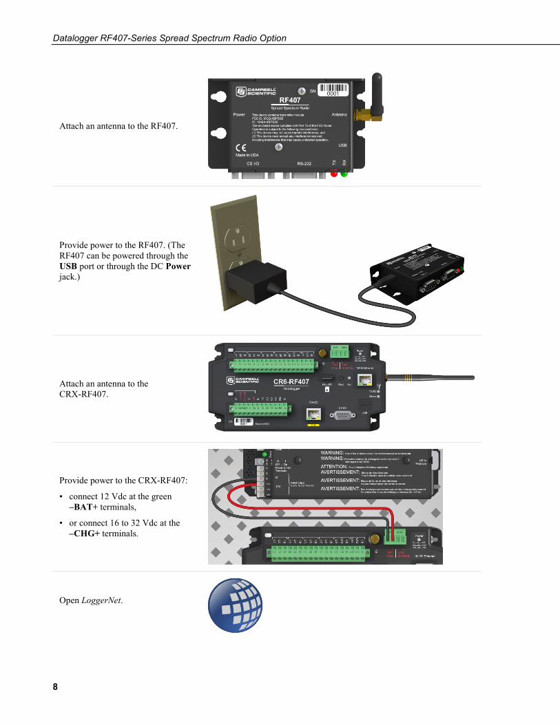
Attach an antenna to the RF407.
Provide power to the RF407. (The RF407 can be powered through the USB port or through the DC Power jack.)
Attach an antenna to the CRX-RF407.
Provide power to the CRX-RF407:
• connect 12 Vdc at the green –BAT+ terminals,
• or connect 16 to 32 Vdc at the –CHG+ terminals.
Open LoggerNet.
Datalogger RF407-Series Spread Spectrum Radio Option
9
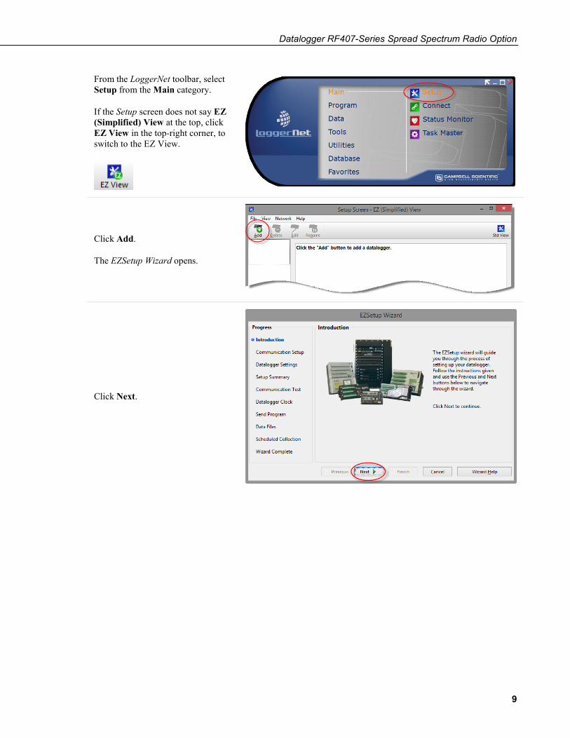
From the LoggerNet toolbar, select Setup from the Main category.
If the Setup screen does not say EZ (Simplified) View at the top, click EZ View in the top-right corner, to switch to the EZ View.
Click Add.
The EZSetup Wizard opens.
Click Next.

Datalogger RF407-Series Spread Spectrum Radio Option
10
Select CR6Series or CR300Series depending on your datalogger. Click Next.
Select Direct Connect. Click Next.
In the list of available communication ports, click RF407-Series (COMnn), where nn is the COM port number assigned by your PC. Click Next.
(Note that you choose RF407-Series (COMnn) to select the USB port to which the RF407 is attached. LoggerNet sees the CRX-RF407 as directly connected to this port. The RF407-to-datalogger link does not need to be indicated in LoggerNet.)

Datalogger RF407-Series Spread Spectrum Radio Option
11
Enter the PakBus Address of your datalogger. The default address is 1. Keep all other defaults. Click Next.
Leave the datalogger security settings at their default values. Click Next.
The Communication Setup Summary screen shows a summary of the settings that you entered. Click Next.

Datalogger RF407-Series Spread Spectrum Radio Option
12
Make sure that Yes is selected. Click Next.
LoggerNet attempts to communicate with the CRX-RF407 and, if successful, the EZSetup Wizard advances to the Communication Test Succeeded screen. (If communication is unsuccessful, click Previous and verify all of the settings are correct.)
Click Next.
Click Set Datalogger Clock, and then click Finish.
The datalogger clock is set to the PC clock, the EZSetup Wizard closes.

Datalogger RF407-Series Spread Spectrum Radio Option
13
The CRX-RF407 is added to the Setup screen. (Note that it will be named CR6Series or CR300Series. The radio option will not be indicated.)
Use LoggerNet Connect to connect to the datalogger, send programs, and view and collect data.

Datalogger RF407-Series Spread Spectrum Radio Option
14
2.2 PC with RF407 to Multiple CRX-RF407s The Basic Procedure can be extended to include multiple CRX-RF407s in the system.
CRX-RF407
RF407 CRX-RF07
CRX-RF407 PC Running LoggerNet
/ PC400
With multiple CRX-RF407s, DevConfig must be used to give each CRX-RF407 a unique PakBus Address. This changes the hardware setting in the CRX-RF407.
Most Campbell Scientific devices come from the factory with a default PakBus address of 1. For this reason, it is best not to assign PakBus address 1 to any device in the network. Then, if a new device with default settings is added to the system, it will not create a conflict.
NOTE

Datalogger RF407-Series Spread Spectrum Radio Option
15
These unique PakBus® addresses must be entered on the Datalogger Settings tab of the LoggerNet EZSetup Wizard. This change is to make the software settings (LoggerNet) match the change we made in the hardware settings using DevConfig.
Once you have used the EZSetup Wizard to add all of the dataloggers in your network, they will all appear on the Setup screen.

Datalogger RF407-Series Spread Spectrum Radio Option
16
2.3 CRX-RF407 as a Router The previous procedure can be extended to use one CRX-RF407 as a router in the network to go around an obstacle such as a hill or to reach longer distances.
RF407
Leaf CRX-RF407
Leaf CRX-RF407
Router CRX-RF407
PC Running LoggerNet
/ PC400
This requires only a few changes to the previous procedure.
First, use DevConfig to connect to the CRX-RF407 that will be used as a router. On the Com Ports Settings tab, set Select the ComPort to RF. Set the Beacon Interval to 60 seconds (or the amount of time you are willing to wait for the leaf dataloggers in the network to be discovered) and the Verify Interval to something slightly greater than the expected communication interval between the router and the leaf dataloggers in the network. For example, the following screenshot shows the Verify Interval set to 90 seconds.

Datalogger RF407-Series Spread Spectrum Radio Option
17
Next, use the Advanced tab in DevConfig to set Is Router to True in the CRX-RF407 that will act as a router.
As in the previous example, DevConfig should be used to give each CRX-RF407 in the network a unique PakBus Address.

Datalogger RF407-Series Spread Spectrum Radio Option
18
To set up the network in LoggerNet, select Setup from the Main category. If the Setup screen says EZ (Simplified) View at the top, click Std View in the top-right corner to switch to the Standard View. Select Add Root | ComPort | PakBusPort (PakBus Loggers) | CR6Series or CR300Series (the type of datalogger that will be used as a router). Close the Add selection window. Select the ComPort in the network map. Use the ComPort Connection drop-down list to select the COM port assigned to the RF407-Series.
Select the PakBusPort in the network map. Select the PakBus Port Always Open checkbox. If it is possible that LoggerNet could communicate with any other dataloggers in the network without going through the router CRX-RF407 and you wish to prevent this, set the Beacon Interval to 00 h 00 m 00s.
Datalogger RF407-Series Spread Spectrum Radio Option
19
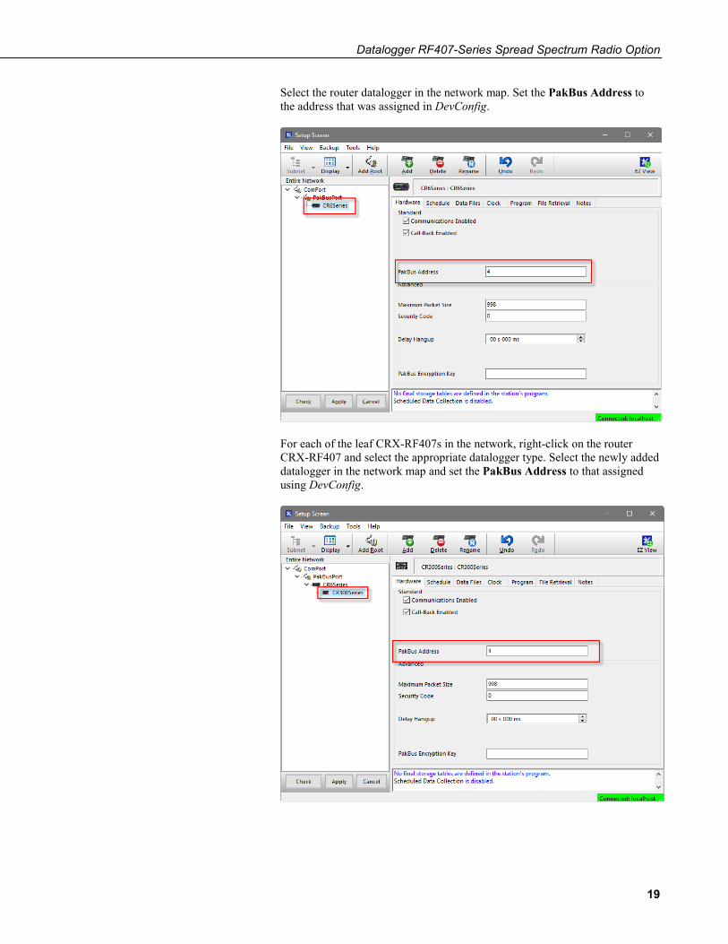
Select the router datalogger in the network map. Set the PakBus Address to the address that was assigned in DevConfig.
For each of the leaf CRX-RF407s in the network, right-click on the router CRX-RF407 and select the appropriate datalogger type. Select the newly added datalogger in the network map and set the PakBus Address to that assigned using DevConfig.

Datalogger RF407-Series Spread Spectrum Radio Option
20
After all of the leaf dataloggers have been added to the network map, click Apply.
All of the dataloggers will be added to the Connect screen, where you can connect to each datalogger, send programs, and view and collect data.
Datalogger RF407-Series Spread Spectrum Radio Option
21
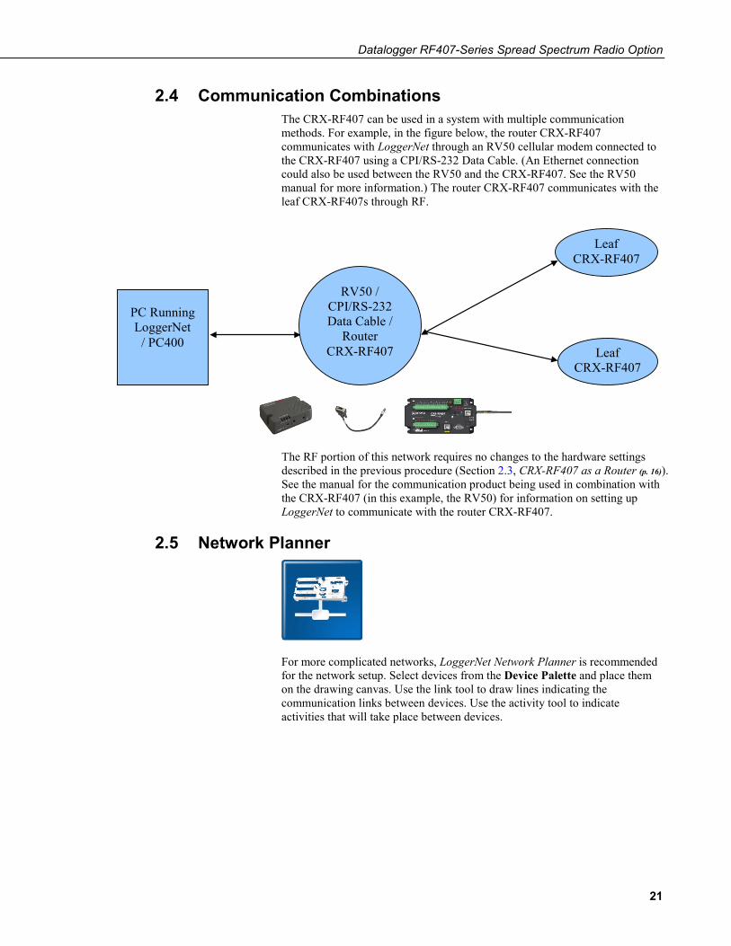
2.4 Communication Combinations The CRX-RF407 can be used in a system with multiple communication methods. For example, in the figure below, the router CRX-RF407 communicates with LoggerNet through an RV50 cellular modem connected to the CRX-RF407 using a CPI/RS-232 Data Cable. (An Ethernet connection could also be used between the RV50 and the CRX-RF407. See the RV50 manual for more information.) The router CRX-RF407 communicates with the leaf CRX-RF407s through RF.
Leaf CRX-RF407
Leaf CRX-RF407
PC Running LoggerNet
/ PC400
RV50 / CPI/RS-232 Data Cable /
Router CRX-RF407
The RF portion of this network requires no changes to the hardware settings described in the previous procedure (Section 2.3, CRX-RF407 as a Router (p. 16)). See the manual for the communication product being used in combination with the CRX-RF407 (in this example, the RV50) for information on setting up LoggerNet to communicate with the router CRX-RF407.
2.5 Network Planner
For more complicated networks, LoggerNet Network Planner is recommended for the network setup. Select devices from the Device Palette and place them on the drawing canvas. Use the link tool to draw lines indicating the communication links between devices. Use the activity tool to indicate activities that will take place between devices.

Datalogger RF407-Series Spread Spectrum Radio Option
22
Network Planner calculates the optimum settings for each device in the network and allows you to send these settings to the device. If any change is made to a device in the network, that change is propagated to every affected device setting. Network Planner can then use the information entered to configure LoggerNet Setup.
Refer to the Network Planner help for more information.
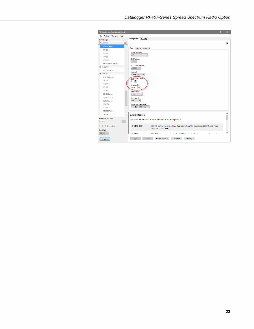
3. Troubleshooting If there are intermittent communication problems with the above setups, there may be another network in the area causing interference. To help remove the interference, use DevConfig to change the Network ID and RF Hop Sequence in all RF407s and CRX-RF407s to a different value. Each of these settings must have the same value in all RF407s and CRX-RF407s. For example, the Network ID in all devices could be set to 1726, and the RF Hop Sequence in all devices could be set to 1. This is just an example. The Network ID can be any number between 0 and 32767. The RF Hop Sequence can be any number between 0 and 7 in an RF407 or RF412 network; it can be any number between 0 and 9 in an RF422 network.
Datalogger RF407-Series Spread Spectrum Radio Option
23

Datalogger RF407-Series Spread Spectrum Radio Option
24

Campbell Scientific Companies
Campbell Scientific, Inc. 815 West 1800 North Logan, Utah 84321 UNITED STATES
www.campbellsci.com • [email protected]
Campbell Scientific Africa Pty. Ltd. PO Box 2450
Somerset West 7129 SOUTH AFRICA
www.campbellsci.co.za • [email protected]
Campbell Scientific Southeast Asia Co., Ltd. 877/22 Nirvana@Work, Rama 9 Road
Suan Luang Subdistrict, Suan Luang District Bangkok 10250
THAILAND www.campbellsci.asia • [email protected]
Campbell Scientific Australia Pty. Ltd. PO Box 8108
Garbutt Post Shop QLD 4814 AUSTRALIA
www.campbellsci.com.au • [email protected]
Campbell Scientific (Beijing) Co., Ltd. 8B16, Floor 8 Tower B, Hanwei Plaza
7 Guanghua Road Chaoyang, Beijing 100004
P.R. CHINA www.campbellsci.com • [email protected]
Campbell Scientific do Brasil Ltda. Rua Apinagés, nbr. 2018 ─ Perdizes CEP: 01258-00 ─ São Paulo ─ SP
BRASIL www.campbellsci.com.br • [email protected]
Campbell Scientific Canada Corp. 14532 – 131 Avenue NW Edmonton AB T5L 4X4
CANADA www.campbellsci.ca • [email protected]
Campbell Scientific Centro Caribe S.A. 300 N Cementerio, Edificio Breller
Santo Domingo, Heredia 40305 COSTA RICA
www.campbellsci.cc • [email protected]
Campbell Scientific Ltd. Campbell Park
80 Hathern Road Shepshed, Loughborough LE12 9GX
UNITED KINGDOM www.campbellsci.co.uk • [email protected]
Campbell Scientific Ltd. 3 Avenue de la Division Leclerc
92160 ANTONY FRANCE
www.campbellsci.fr • [email protected]
Campbell Scientific Ltd. Fahrenheitstraße 13
28359 Bremen GERMANY
www.campbellsci.de • [email protected]
Campbell Scientific Spain, S. L. Avda. Pompeu Fabra 7-9, local 1
08024 Barcelona SPAIN
www.campbellsci.es • [email protected]
Please visit www.campbellsci.com to obtain contact information for your local US or international representative.