dataman™ 100 - cimtec automation and hold the trigger button for at least 3 seconds. this trains...
TRANSCRIPT

COGNEX®
DataMan™ 100
Quick Reference Guide

1
2
3
4
5
Getting Started
Setting up your DataMan
Connect your DataMan
Using your Dataman
Product contents • Accessories • Mechanical specifications • Product features • Software Installation Page 2
Page 8
Page 14
Page 18
Setting the DataMan focus position • Working distance (scan maps) • Mounting options and guidelines
Connection types • Wiring discrete inputs • Wiring discrete outputs • Examples
Trigger types • Training • Using the Setup Tool
Reference Information Page 24Specifications • Precautions • Support Information

COGNEX
DO NOT HOT PLUG
DM100 IOBOXIOB10 200-3001-R1R
RS232 USB24VDC
— +
OUTPUT
0 1 C 0 1 C
INPUT
DataMan 100 Systems
DataMan 100 with IDQuick(DMR-100Q-00)
DataMan 100 Accessories
CD-ROM (Setup Tool and Drivers)(206-6400-220)
Quick Reference Guide(590-7013)
DataMan I/O Module (DM100-IOBOX-000)
Mounting bracket (DM100-UBRK-000)
RS-232 adapter cable with power tap (DM100-RS232-000)
Power supply (DM100-PWR-000)
USB adapter cable with power tap (DM100-USB-000)
DataMan 100 with IDMax(DMR-100X-00)
Basic Accessory Kit (DM100-BAK-000)
37
19.5
55
22.122.7
43.5
42
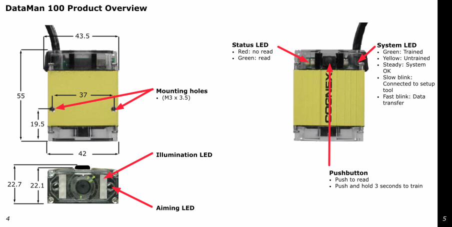
DataMan 100 Product Overview
Aiming LED
Illumination LED
Mounting holes (M3 x 3.5)•
Status LEDRed: no readGreen: read
•
•
PushbuttonPush to readPush and hold 3 seconds to train
•
•
System LEDGreen: TrainedYellow: UntrainedSteady: System OKSlow blink: Connected to setup toolFast blink: Data transfer
•
•
•
•
•
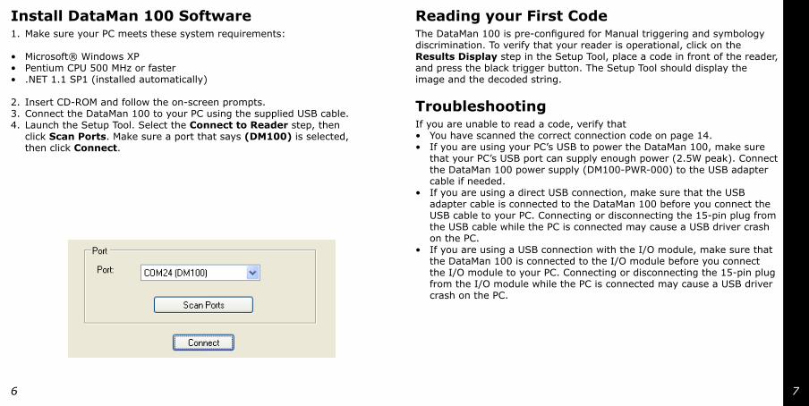
Install DataMan 100 SoftwareMake sure your PC meets these system requirements:
Microsoft® Windows XPPentium CPU 500 MHz or faster.NET 1.1 SP1 (installed automatically)
Insert CD-ROM and follow the on-screen prompts.Connect the DataMan 100 to your PC using the supplied USB cable. Launch the Setup Tool. Select the Connect to Reader step, then click Scan Ports. Make sure a port that says (DM100) is selected, then click Connect.
1.
•••
2.3.4.
Reading your First CodeThe DataMan 100 is pre-configured for Manual triggering and symbology discrimination. To verify that your reader is operational, click on the Results Display step in the Setup Tool, place a code in front of the reader, and press the black trigger button. The Setup Tool should display the image and the decoded string.
TroubleshootingIf you are unable to read a code, verify that
You have scanned the correct connection code on page 14.If you are using your PC’s USB to power the DataMan 100, make sure that your PC’s USB port can supply enough power (2.5W peak). Connect the DataMan 100 power supply (DM100-PWR-000) to the USB adapter cable if needed.If you are using a direct USB connection, make sure that the USB adapter cable is connected to the DataMan 100 before you connect the USB cable to your PC. Connecting or disconnecting the 15-pin plug from the USB cable while the PC is connected may cause a USB driver crash on the PC.If you are using a USB connection with the I/O module, make sure that the DataMan 100 is connected to the I/O module before you connect the I/O module to your PC. Connecting or disconnecting the 15-pin plug from the I/O module while the PC is connected may cause a USB driver crash on the PC.
••
•
•

COGNEX
5 mil: 34-50 mm
10 mil: 21-56 mm
15 mil: 11-70 mm
20 mil: 8-75 mm
10540
65
(40 mm) 50
50
0
50
100 150 2001
2
3
Setting DataMan 100 Focus PositionDataMan can operate in one of three distance ranges. To set the focus position:
Reading Distances (40 mm)
Remove screws and lens cover.
Set focus position.
Replace lens cover and screws.

0
COGNEX
10 mil: 32-88 mm
15 mil: 28-105 mm
20 mil: 18-115 mm
30 mil: 10-140 mm105
40
65
(65 mm) 50
50
0
50
100 150 200
COGNEX
(105 MM) 50
50
0
50
100 150 200
15 mil: 35-170 mm
20 mil: 27-185 mm
30 mil: 15-225 mm
105
40
65
10 mil: 61-131 mm
Reading Distances (65 mm) Reading Distances (105 mm)

M3 x 5
15°
Universal Mounting Bracket Optimizing Lighting
Mounting the DataMan 100 at a slight angle (15°) can reduce reflections and improve reader performance.
COGNEX
DO NOT HOT PLUG
DM100 IOBOXIOB10 200-3001-R1R
RS232 USB24VDC
— +
OUTPUT
0 1 C 0 1 C
INPUT
COGNEX
DO NOT HOT PLUG
DM100 IOBOXIOB10 200-3001-R1R
RS232 USB24VDC
— +
OUTPUT
0 1 C 0 1 C
INPUT
1
2
1
2
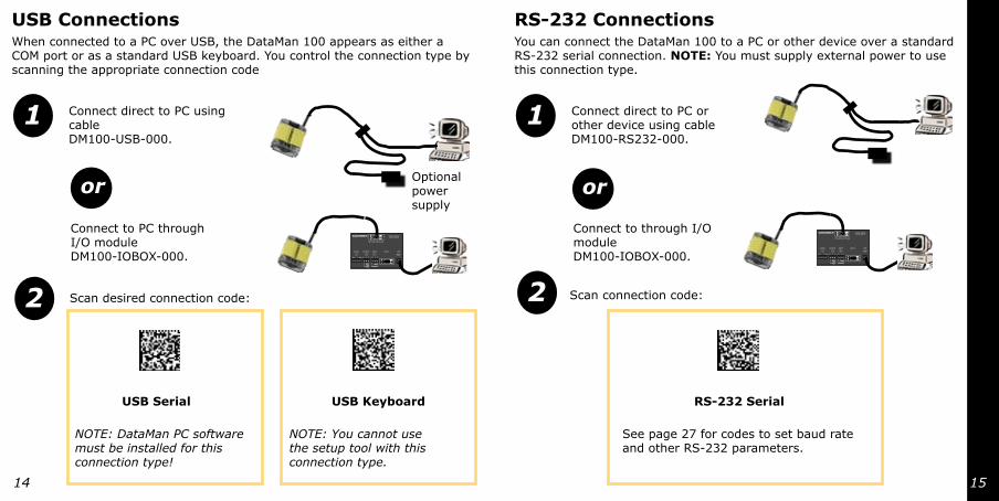
USB ConnectionsWhen connected to a PC over USB, the DataMan 100 appears as either a COM port or as a standard USB keyboard. You control the connection type by scanning the appropriate connection code
NOTE: DataMan PC software must be installed for this connection type!
Connect direct to PC using cable DM100-USB-000.
Connect to PC through I/O module DM100-IOBOX-000.
Scan desired connection code:
RS-232 Connections You can connect the DataMan 100 to a PC or other device over a standard RS-232 serial connection. NOTE: You must supply external power to use this connection type.
or
USB Serial USB Keyboard
NOTE: You cannot use the setup tool with this connection type.
Connect direct to PC or other device using cable DM100-RS232-000.
Connect to through I/O module DM100-IOBOX-000.
or
RS-232 Serial
Scan connection code:
See page 27 for codes to set baud rate and other RS-232 parameters.
Optional power supply
COGNEX
DO NOT HOT PLUG
DM100 IOBOXIOB10 200-3001-R1R
RS232 USB24VDC
— +
OUTPUT
0 1 C 0 1 C
INPUT
1 2 3 4
CO
GN
EX
DO
NO
T H
OT P
LUG
DM
100 IOBO
XIO
B10 200-3001-R
1R
RS232
USB
24VD
C
—+
OU
TPU
T
01
C0
1C
INPU
T
24VDC
–
+
CO
GN
EX
DO
NO
T H
OT P
LUG
DM
100 IOBO
XIO
B10 200-3001-R
1R
RS232
USB
24VD
C
—+
OU
TPU
T
01
C0
1C
INPU
T
24VDC
–
+
1
2
3
4
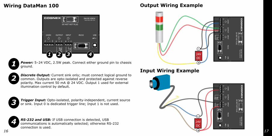
Wiring DataMan 100
Input Wiring Example
Output Wiring Example
Power: 5–24 VDC, 2.5W peak. Connect either ground pin to chassis ground.
Discrete Output: Current sink only; must connect logical ground to common. Outputs are opto-isolated and protected against reverse polarity. Max current 50 mA @ 24 VDC. Output 1 used for external illumination control by default.
Trigger Input: Opto-isolated, polarity-independent, current source or sink. Input 0 is dedicated trigger line; Input 1 is not used.
RS-232 and USB: If USB connection is detected, USB communications is automatically selected; otherwise RS-232 connection is used.

1
2
3
4
1
2
3
DataMan 100 Trigger TypesDataMan decodes when you tell it to. You can trigger a read by
DataMan 100 Trigger ModesDataMan supports three trigger modes. The trigger mode determines what happens when a trigger signal is received.
Pressing and holding the trigger button.
Sending a pulse on Input-0 line.
Sending a command on the RS-232 serial line. (You must be using the RS-232 communications type.
In Single Trigger Mode, DataMan 100 acquires and attempts to decode an image as soon as the trigger is received. You can use the setup tool to define a trigger delay.
In Presentation Mode, continuously scans for and attempts to decode symbols. Whenever a symbol is present in the field of view, DataMan 100 decodes it. You can specify a latency period between read attempts, and you can configure the DataMan 100 to not decode the same code multiple times using the setup tool.
In Manual Trigger Mode, DataMan continuously acquires and attempts to decode images as long as the trigger button is held down.
Clicking the Trigger button in the Setup tool.

0
1
2
3
DataMan 100 TrainingFor best performance, you can train DataMan. Train DataMan by placing a code in front of the reader and doing one of the following:
DataMan 100 Training FeedbackDataMan reports the status of the tuning operation using its signalling LEDs:
Press and hold the trigger button for at least 3 seconds. This trains the code and optimizes lighting.
In the Display pane of the Setup Tool you can click the Train Code button to train the code, and you can click the Optimize Lighting button to optimize lighting.
Displays steady green if trained, steady yellow if untrained.
Flashes red between 1 and 3 times when training attempt is complete. Greater numbers of flashes indicate better training results.
Click and hold the trigger button in the Setup for at least 3 seconds. This trains the code and optimizes lighting.
Training and Trigger ModesTraining is supported for the trigger modes shown below:
Trigger Mode Training Supported?
Single Yes
Presentation No
Manual No
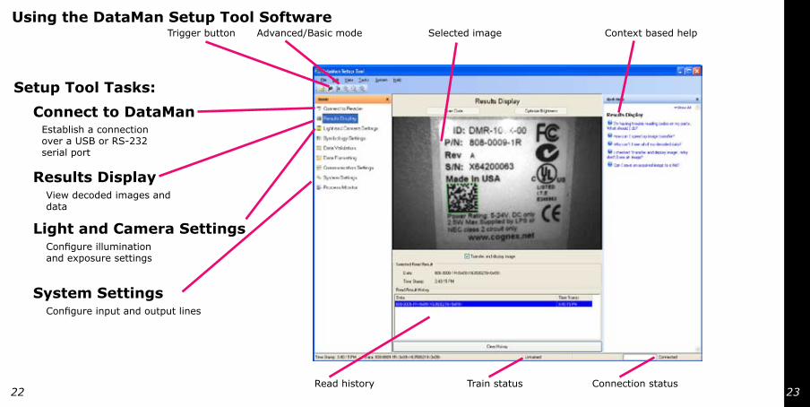
Using the DataMan Setup Tool Software
Read history
Context based help
Connection status
Trigger button Selected imageAdvanced/Basic mode
Setup Tool Tasks:
Establish a connection over a USB or RS-232 serial port
Connect to DataMan
View decoded images and data
Results Display
Configure illumination and exposure settings
Light and Camera Settings
Configure input and output lines
System Settings
Train status
1
2
3
4
5
6
7
8
9
10
11
12
13
14
15
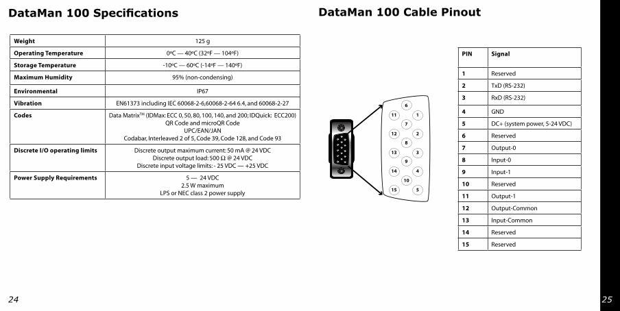
DataMan 100 Specifications DataMan 100 Cable Pinout
Weight 125 g
Operating Temperature 0ºC — 40ºC (32ºF — 104ºF)
Storage Temperature -10ºC — 60ºC (-14ºF — 140ºF)
Maximum Humidity 95% (non-condensing)
Environmental IP67
Vibration EN61373 including IEC 60068-2-6,60068-2-64 6.4, and 60068-2-27
Codes Data MatrixTM (IDMax: ECC 0, 50, 80, 100, 140, and 200; IDQuick: ECC200)QR Code and microQR Code
UPC/EAN/JANCodabar, Interleaved 2 of 5, Code 39, Code 128, and Code 93
Discrete I/O operating limits Discrete output maximum current: 50 mA @ 24 VDC Discrete output load: 500 Ω @ 24 VDC
Discrete input voltage limits: - 25 VDC — +25 VDC
Power Supply Requirements 5 — 24 VDC 2.5 W maximum
LPS or NEC class 2 power supply
PIN Signal
1 Reserved
2 TxD (RS-232)
3 RxD (RS-232)
4 GND
5 DC+ (system power, 5-24 VDC)
6 Reserved
7 Output-0
8 Input-0
9 Input-1
10 Reserved
11 Output-1
12 Output-Common
13 Input-Common
14 Reserved
15 Reserved

++
–
–
+ – + –
+–
PLC (sourcing) DM100 (sinking)
Out 0/1
COM
10
IN
COM
PLC (sinking) DM100 (sinking)
Out 0/1
R1
COM
IN
COM
10
Pull-up resistor required (R1):470 @ 5V2.2 K @ 12V4.7 K @ 24V
Device (sinking)
Load
DM100 (sinking)
Out 0/1
R1
COM
10
Pull-up resistor required (R1):470 @ 5V2.2 K @ 12V4.7 K @ 24V
PLC (sourcing) DM100 (sinking)
In 0
COM
OUT
COM
3 K
PLC (sinking) DM100 (sourcing)
In 0
COM
OUT
COM
3 K
Device (TTL) DM100 (load)
In 0
COM
3 K
Digital Output Wiring Digital Input Wiring

Corded Reader Configuration Codes (v2.1)
5 / 6
Function Value Code
Connection Type Keyboard Emulation / USB-Keyboard
9600 BPS
19200 BPS
*38400 BPS
57600 BPS
RS-232 Baud Rate
115200 BPS
8 Data, 1 Stop, Even
RS-232 Word Length
*8 Data, 1 Stop, None
Corded Reader Configuration Codes (v2.1)
5 / 6
Function Value Code
Connection Type Keyboard Emulation / USB-Keyboard
9600 BPS
19200 BPS
*38400 BPS
57600 BPS
RS-232 Baud Rate
115200 BPS
8 Data, 1 Stop, Even
RS-232 Word Length
*8 Data, 1 Stop, None
Corded Reader Configuration Codes (v2.1)
5 / 6
Function Value Code
Connection Type Keyboard Emulation / USB-Keyboard
9600 BPS
19200 BPS
*38400 BPS
57600 BPS
RS-232 Baud Rate
115200 BPS
8 Data, 1 Stop, Even
RS-232 Word Length
*8 Data, 1 Stop, None
Corded Reader Configuration Codes (v2.1)
5 / 6
Function Value Code
Connection Type Keyboard Emulation / USB-Keyboard
9600 BPS
19200 BPS
*38400 BPS
57600 BPS
RS-232 Baud Rate
115200 BPS
8 Data, 1 Stop, Even
RS-232 Word Length
*8 Data, 1 Stop, None
Corded Reader Configuration Codes (v2.1)
5 / 6
Function Value Code
Connection Type Keyboard Emulation / USB-Keyboard
9600 BPS
19200 BPS
*38400 BPS
57600 BPS
RS-232 Baud Rate
115200 BPS
8 Data, 1 Stop, Even
RS-232 Word Length
*8 Data, 1 Stop, None
Corded Reader Configuration Codes (v2.1)
5 / 6
Function Value Code
Connection Type Keyboard Emulation / USB-Keyboard
9600 BPS
19200 BPS
*38400 BPS
57600 BPS
RS-232 Baud Rate
115200 BPS
8 Data, 1 Stop, Even
RS-232 Word Length
*8 Data, 1 Stop, None
Corded Reader Configuration Codes (v2.1)
5 / 6
Function Value Code
Connection Type Keyboard Emulation / USB-Keyboard
9600 BPS
19200 BPS
*38400 BPS
57600 BPS
RS-232 Baud Rate
115200 BPS
8 Data, 1 Stop, Even
RS-232 Word Length
*8 Data, 1 Stop, None
Corded Reader Configuration Codes (v2.1)
6 / 6
Function Value Code
RS-232 Word Length
8 Data, 1 Stop, Odd
*RTS/CTS Off
RS-232 Handshaking
RTS/CTS On
*USA
Germany
France
Spain
Keyboard Country
Japan
i
Warnings and Notices
8-1-even
8-1-none
115,200 Baud
8-1-odd
RS-232 Parameter Codes
9600 Baud
19,200 Baud
38,400 Baud
57,600 Baud
CAUTION: This device requires the use of an LPS or NEC class 2 power supply.
CAUTION: Do not connect or disconnect this device from the I/O module or 15-pin USB adapter cable while the I/O module or adapter cable is connected to a PC .
NOTE: For product support, contact http://support.cognex.com
COGNEX®
590-7013
Copyright © 2006 Cognex Corporation All Rights Reserved. This document may not be copied in whole or in part, nor transferred to any other media or language, without the written permission of Cognex Corporation. The hardware and portions of the software described in this document may be covered by one or more of the U.S. patents listed on the
Cognex web site http://www.cognex.com/patents.asp. Other U.S. and foreign patents are pending. Cognex, the Cognex logo, and DataMan are trademarks, or registered trademarks, of Cognex Corporation.