datasheet and operating guide · pdf file• small package size • single supply...
TRANSCRIPT
ORDERING INFORMATIONPART NO DESCRIPTIONLDTC0520 500 mA LD / ±2.2 A TEC ControllerLDTC1020 1.0 A LD / ±2.2 A TEC Controller
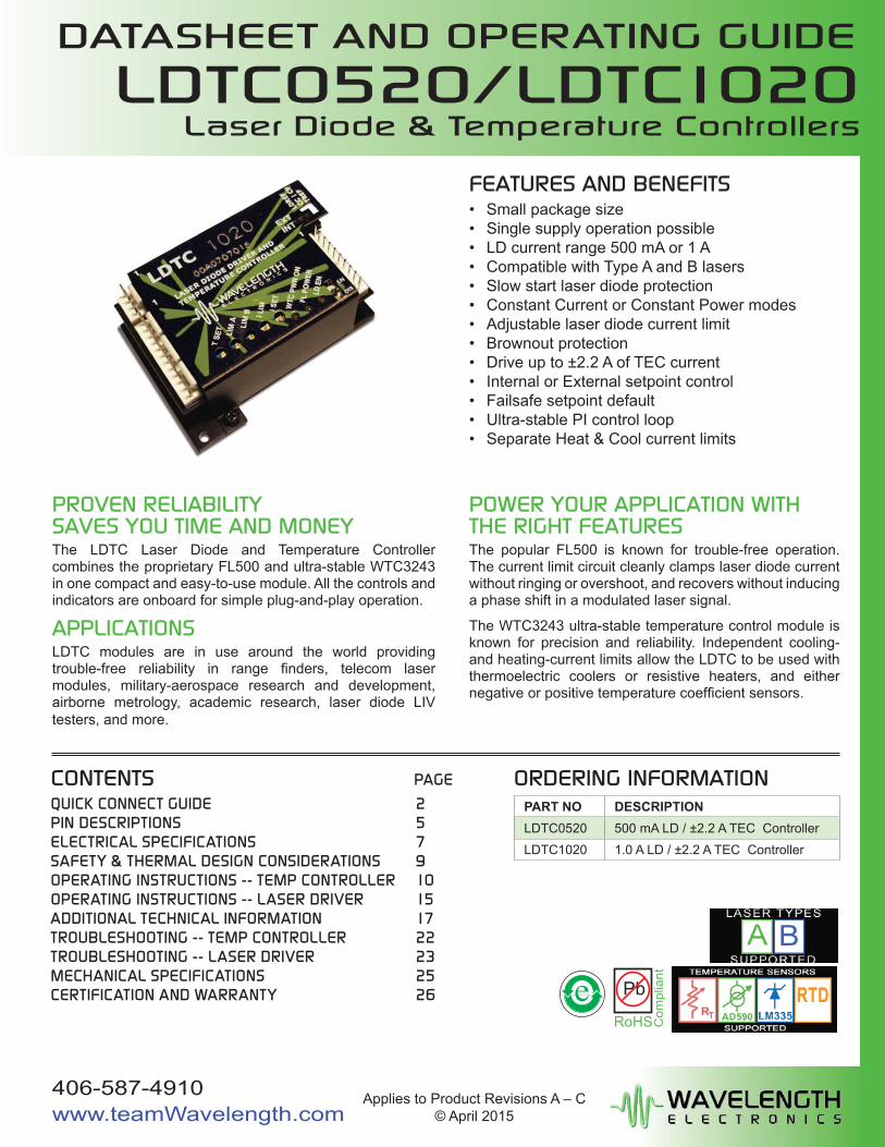
PROVEN RELIABILITYSAVES YOU TIME AND MONEYThe LDTC Laser Diode and Temperature Controller combines the proprietary FL500 and ultra-stable WTC3243 in one compact and easy-to-use module. All the controls and indicators are onboard for simple plug-and-play operation.
APPLICATIONSLDTC modules are in use around the world providing trouble-free reliability in range fi nders, telecom laser modules, military-aerospace research and development, airborne metrology, academic research, laser diode LIV testers, and more.
POWER YOUR APPLICATION WITH THE RIGHT FEATURESThe popular FL500 is known for trouble-free operation. The current limit circuit cleanly clamps laser diode current without ringing or overshoot, and recovers without inducing a phase shift in a modulated laser signal.
The WTC3243 ultra-stable temperature control module is known for precision and reliability. Independent cooling- and heating-current limits allow the LDTC to be used with thermoelectric coolers or resistive heaters, and either negative or positive temperature coeffi cient sensors.
FEATURES AND BENEFITS• Small package size• Single supply operation possible• LD current range 500 mA or 1 A• Compatible with Type A and B lasers• Slow start laser diode protection• Constant Current or Constant Power modes• Adjustable laser diode current limit• Brownout protection• Drive up to ±2.2 A of TEC current• Internal or External setpoint control• Failsafe setpoint default• Ultra-stable PI control loop• Separate Heat & Cool current limits
CONTENTSQUICK CONNECT GUIDE 2PIN DESCRIPTIONS 5ELECTRICAL SPECIFICATIONS 7SAFETY & THERMAL DESIGN CONSIDERATIONS 9OPERATING INSTRUCTIONS -- TEMP CONTROLLER 10OPERATING INSTRUCTIONS -- LASER DRIVER 15ADDITIONAL TECHNICAL INFORMATION 17TROUBLESHOOTING -- TEMP CONTROLLER 22TROUBLESHOOTING -- LASER DRIVER 23MECHANICAL SPECIFICATIONS 25CERTIFICATION AND WARRANTY 26 e Pb
RoHS Com
plia
nt
PAGE
Applies to Product Revisions A – C© April 2015
406-587-4910www.teamWavelength.com
LDTC0520/LDTC1020Laser Diode & Temperature Controllers
DATASHEET AND OPERATING GUIDE
© 2015 www.teamWavelength.com 2
LDTC0520 / LDTC1020 LASER DIODE AND TEMPERATURE CONTROLLER
J1
J2
J3
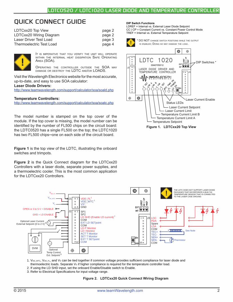
Status LEDsLaser Current Enable
Laser Current SetpointLaser Current Limit
Temperature Current Limit B
Temperature SetpointTemperature Current Limit A
DIP Switches *
DIP Switch FunctionsLDREF = Internal vs. External Laser Diode SetpointCC | CP = Constant Current vs. Constant Power Control ModeTREF = Internal vs. External Temperature Setpoint
* DO NOT CHANGE SWITCH POSITIONS WHILE THE OUTPUT
IS ENABLED; DOING SO MAY DAMAGE THE LOAD.!
Figure 1. LDTCxx20 Top View
QUICK CONNECT GUIDELDTCxx20 Top View page 2LDTCxx20 Wiring Diagram page 2Laser Driver Test Load page 3Thermoelectric Test Load page 4
!IT IS IMPERATIVE THAT YOU VERIFY THE UNIT WILL OPERATE WITHIN THE INTERNAL HEAT DISSIPATION SAFE OPERATING AREA (SOA).
OPERATING THE CONTROLLER OUTSIDE THE SOA MAY DAMAGE OR DESTROY THE LDTC AND/OR LOADS.
Visit the Wavelength Electronics website for the most accurate, up-to-date, and easy to use SOA calculator:Laser Diode Drivers:http://www.teamwavelength.com/support/calculator/soa/soald.phphttp://www.teamwavelength.com/support/calculator/soa/soald.php
Temperature Controllers:Temperature Controllers:http://www.teamwavelength.com/support/calculator/soa/soatc.phphttp://www.teamwavelength.com/support/calculator/soa/soatc.php
The model number is stamped on the top cover of the module. If the top cover is missing, the model number can be identifi ed by the number of FL500 chips on the circuit board: the LDTC0520 has a single FL500 on the top; the LDTC1020 has two FL500 chips─one on each side of the circuit board.
Figure 1 is the top view of the LDTC, illustrating the onboard switches and trimpots.
Figure 2 is the Quick Connect diagram for the LDTCxx20 Controllers with a laser diode, separate power supplies, and a thermoelectric cooler. This is the most common application for the LDTCxx20 Controllers.
VDD_FLVDD_WTCVSGND
SP1SP2LD SHD (Enable LD current)COMEXT LD SETpointCOMLD P MonitorLD I MonitorACT T MonitorSET T MonitorEXT T SETpointCOM
LDCPDASpareLDACOMTEC+TEC-SEN+SEN-COM
J1
J2
J3
VDD_WTC
VDD_FL
VS
-+ See Note
Thermistor
DVM
OPEN or 3 to 5 V = DISABLE
GND = LD ENABLE
1
1
4
12
1
10
Optional Laser Current External Setpoint (0 to 2 V)
Optional Temp ControlExt. Setpoint
11
2
3
1
1. VDD_WTC, VDD_FL, and VS can be tied together if common voltage provides sufficient compliance for laser diode and thermoelectric loads. Separate VS if higher compliance is required for the temperature controller load.2. If using the LD SHD input, set the onboard Enable/Disable switch to Enable.3. Refer to Electrical Specifications for input voltage range.
3
!THE LDTC DOES NOT SUPPORT LASER DIODE PACKAGES THAT INCORPORATE A BUILT-IN TEMPERATURE SENSOR THAT IS CONNECTED TO THE LASER CASE GROUND.
Figure 2. LDTCxx20 Quick Connect Wiring Diagram
© 2015 www.teamWavelength.com 3
LDTC0520 / LDTC1020 LASER DIODE AND TEMPERATURE CONTROLLER
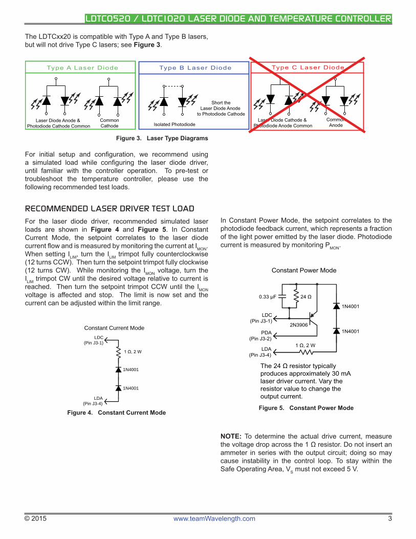
The LDTCxx20 is compatible with Type A and Type B lasers, but will not drive Type C lasers; see Figure 3.
Type A Laser Diode Type B Laser Diode Type C Laser Diode
CommonCathode
Laser Diode Anode & Photodiode Cathode Common Isolated Photodiode
Short theLaser Diode Anode
to Photodiode CathodeCommon
AnodeLaser Diode Cathode &
Photodiode Anode Common
Figure 3. Laser Type Diagrams
For initial setup and confi guration, we recommend using a simulated load while confi guring the laser diode driver, until familiar with the controller operation. To pre-test or troubleshoot the temperature controller, please use the following recommended test loads.
RECOMMENDED LASER DRIVER TEST LOAD
For the laser diode driver, recommended simulated laser loads are shown in Figure 4 and Figure 5. In Constant Current Mode, the setpoint correlates to the laser diode current fl ow and is measured by monitoring the current at IMON. When setting ILIM, turn the ILIM trimpot fully counterclockwise (12 turns CCW). Then turn the setpoint trimpot fully clockwise (12 turns CW). While monitoring the IMON voltage, turn the ILIM trimpot CW until the desired voltage relative to current is reached. Then turn the setpoint trimpot CCW until the IMON voltage is affected and stop. The limit is now set and the current can be adjusted within the limit range.
1N4001
1N4001
LDC(Pin J3-1)
LDA(Pin J3-4)
Constant Current Mode
Figure 4. Constant Current Mode
In Constant Power Mode, the setpoint correlates to the photodiode feedback current, which represents a fraction of the light power emitted by the laser diode. Photodiode current is measured by monitoring PMON.
1N4001
1N40012N3906
0.33 μF
PDA(Pin J3-2)
LDA(Pin J3-4)
LDC(Pin J3-1)
Constant Power Mode
Figure 5. Constant Power Mode
NOTE: To determine the actual drive current, measure the voltage drop across the 1 Ω resistor. Do not insert an ammeter in series with the output circuit; doing so may cause instability in the control loop. To stay within the Safe Operating Area, VS must not exceed 5 V.
© 2015 www.teamWavelength.com 4
LDTC0520 / LDTC1020 LASER DIODE AND TEMPERATURE CONTROLLER
RECOMMENDED THERMOELECTRIC TEST LOAD
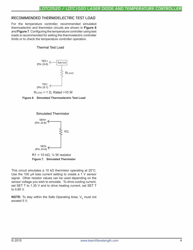
For the temperature controller, recommended simulated thermoelectric and thermistor circuits are shown in Figure 6 and Figure 7. Confi guring the temperature controller using test loads is recommended for setting the thermoelectric controller limits or to check the temperature controller operation.
RLOAD
TEC+(Pin J3-6)
TEC-(Pin J3-7)
RLOAD
IMETER
Figure 6. Simulated Thermoelectric Test Load
R1
SEN-
SEN+
Figure 7. Simulated Thermistor
This circuit simulates a 10 kΩ thermistor operating at 25°C. Use the 100 μA bias current setting to create a 1 V sensor signal. Other resistor values can be used depending on the sensor voltage you wish to simulate. To drive cooling current, set SET T to 1.35 V and to drive heating current, set SET T to 0.85 V.
NOTE: To stay within the Safe Operating Area, VS must not exceed 5 V.
© 2015 www.teamWavelength.com 5
LDTC0520 / LDTC1020 LASER DIODE AND TEMPERATURE CONTROLLER
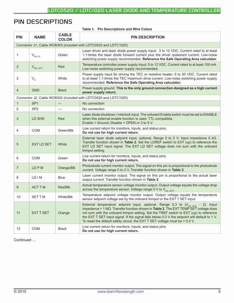
PIN DESCRIPTIONSTable 1. Pin Descriptions and Wire Colors
PIN NAME CABLE COLOR PIN DESCRIPTION
Connector J1, Cable WCB303 (included with LDTC0520 and LDTC1020)
1 VDD_FL GreenLaser driver and laser diode power supply input; 3 to 12 VDC. Current rated to at least 1.1-times the laser diode forward current plus the driver quiescent current. Low-noise switching power supply recommended. Reference the Safe Operating Area calculator.
2 VDD_WTC Red Temperature controller power supply input; 5 to 12 VDC. Current rated to at least 100 mA. Low-noise switching power supply recommended.
3 VS WhitePower supply input for driving the TEC or resistive heater; 5 to 30 VDC. Current rated to at least 1.1-times the TEC maximum drive current. Low-noise switching power supply recommended. Reference the Safe Operating Area calculator.
4 GND Black Power supply ground. This is the only ground connection designed as a high current power supply return.
Connector J2, Cable WCB302 (included with LDTC0520 and LDTC1020)1 SP1 — No connection2 SP2 — No connection
3 LD SHD RedLaser diode shutdown / interlock input. The onboard Enable switch must be set to ENABLE when this external enable function is used. TTL-compatible.Enable = Ground; Disable = OPEN or 3 to 5 V.
4 COM Green/Blk Low current return for monitors, inputs, and status pins. Do not use for high current return.
5 EXT LD SET White
External laser diode setpoint input, optional. Range 0 to 2 V. Input impedance 5 kΩ. Transfer function shown in Table 2. Set the LDREF switch to EXT (up) to reference the EXT LD SET input signal. The EXT LD SET voltage does not sum with the onboard trimpot setting.
6 COM Green Low current return for monitors, inputs, and status pins. Do not use for high current return.
7 LD P M Orange/Blk Photodiode current monitor output. The signal on this pin is proportional to the photodiode current. Voltage range 0 to 2 V. Transfer function shown in Table 2.
8 LD I M Blue Laser current monitor output. The signal on this pin is proportional to the actual laser output current. Transfer function shown in Table 2.
9 ACT T M Red/Blk Actual temperature sensor voltage monitor output. Output voltage equals the voltage drop across the temperature sensor. Voltage range 0 V to VDD_WTC.
10 SET T M White/Blk Temperature setpoint voltage monitor output. Output voltage equals the temperature sensor setpoint voltage set by the onboard trimpot or the EXT T SET input.
11 EXT T SET Orange
External temperature setpoint input, optional. Range 0.3 to (VDD_WTD - 2). Input impedance > 1 MΩ. Transfer function shown in Table 2. The EXT TEMP SET voltage does not sum with the onboard trimpot setting. Set the TREF switch to EXT (up) to reference the EXT T SET input signal. If the signal falls below 0.3 V the setpoint will default to 1 V. To reset the default safety circuit, the EXT T SET voltage must be > 0.4 V.
12 COM Black Low current return for monitors, inputs, and status pins. Do not use for high current return.
Continued ...
© 2015 www.teamWavelength.com 6
LDTC0520 / LDTC1020 LASER DIODE AND TEMPERATURE CONTROLLER
PIN DESCRIPTIONS (CONTINUED)
PIN NAME CABLE COLOR PIN DESCRIPTION
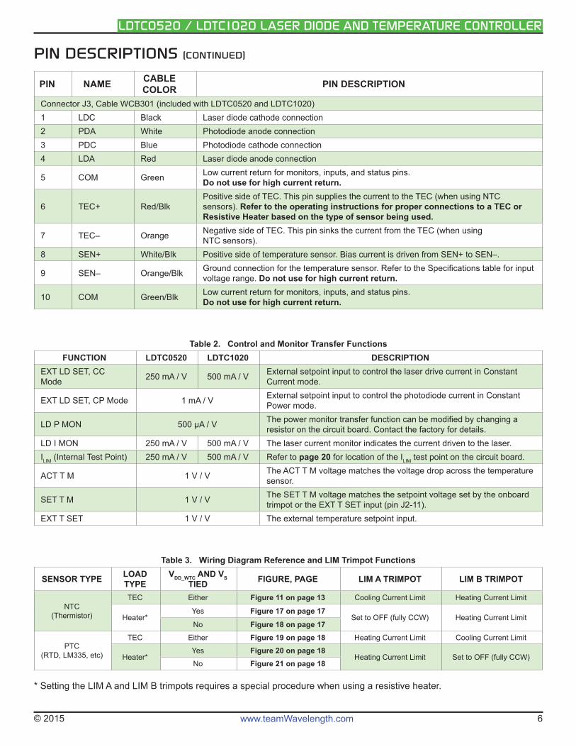
Connector J3, Cable WCB301 (included with LDTC0520 and LDTC1020)1 LDC Black Laser diode cathode connection2 PDA White Photodiode anode connection3 PDC Blue Photodiode cathode connection4 LDA Red Laser diode anode connection
5 COM Green Low current return for monitors, inputs, and status pins. Do not use for high current return.
6 TEC+ Red/BlkPositive side of TEC. This pin supplies the current to the TEC (when using NTC sensors). Refer to the operating instructions for proper connections to a TEC or Resistive Heater based on the type of sensor being used.
7 TEC– Orange Negative side of TEC. This pin sinks the current from the TEC (when using NTC sensors).
8 SEN+ White/Blk Positive side of temperature sensor. Bias current is driven from SEN+ to SEN–.
9 SEN– Orange/Blk Ground connection for the temperature sensor. Refer to the Specifi cations table for input voltage range. Do not use for high current return.
10 COM Green/Blk Low current return for monitors, inputs, and status pins. Do not use for high current return.
Table 2. Control and Monitor Transfer Functions FUNCTION LDTC0520 LDTC1020 DESCRIPTION
EXT LD SET, CC Mode 250 mA / V 500 mA / V External setpoint input to control the laser drive current in Constant
Current mode.
EXT LD SET, CP Mode 1 mA / V External setpoint input to control the photodiode current in Constant Power mode.
LD P MON 500 μA / V The power monitor transfer function can be modifi ed by changing a resistor on the circuit board. Contact the factory for details.
LD I MON 250 mA / V 500 mA / V The laser current monitor indicates the current driven to the laser.ILIM (Internal Test Point) 250 mA / V 500 mA / V Refer to page 20 for location of the ILIM test point on the circuit board.
ACT T M 1 V / V The ACT T M voltage matches the voltage drop across the temperature sensor.
SET T M 1 V / V The SET T M voltage matches the setpoint voltage set by the onboard trimpot or the EXT T SET input (pin J2-11).
EXT T SET 1 V / V The external temperature setpoint input.
Table 3. Wiring Diagram Reference and LIM Trimpot Functions
SENSOR TYPE LOAD TYPE
VDD_WTC AND VS TIED FIGURE, PAGE LIM A TRIMPOT LIM B TRIMPOT
NTC(Thermistor)
TEC Either Figure 11 on page 13 Cooling Current Limit Heating Current Limit
Heater*Yes Figure 17 on page 17
Set to OFF (fully CCW) Heating Current LimitNo Figure 18 on page 17
PTC (RTD, LM335, etc)
TEC Either Figure 19 on page 18 Heating Current Limit Cooling Current Limit
Heater*Yes Figure 20 on page 18
Heating Current Limit Set to OFF (fully CCW)No Figure 21 on page 18
* Setting the LIM A and LIM B trimpots requires a special procedure when using a resistive heater.
© 2015 www.teamWavelength.com 7
LDTC0520 / LDTC1020 LASER DIODE AND TEMPERATURE CONTROLLER
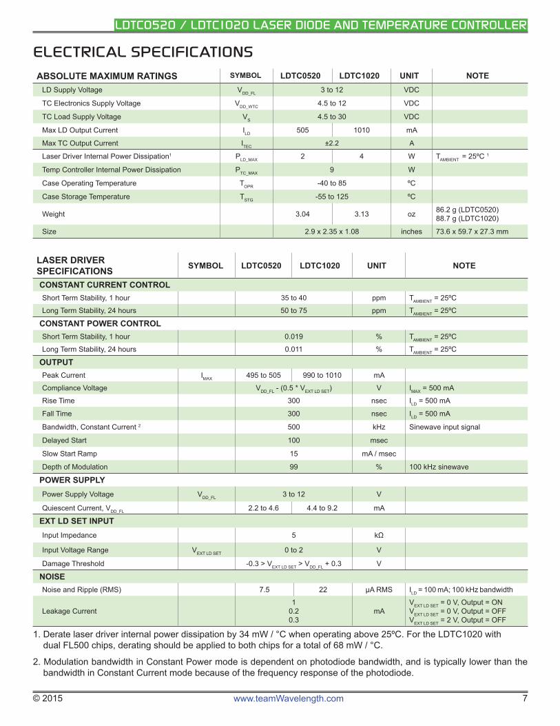
ELECTRICAL SPECIFICATIONS
ABSOLUTE MAXIMUM RATINGS SYMBOL LDTC0520 LDTC1020 UNIT NOTELD Supply Voltage VDD_FL 3 to 12 VDC
TC Electronics Supply Voltage VDD_WTC 4.5 to 12 VDC
TC Load Supply Voltage VS 4.5 to 30 VDC
Max LD Output Current ILD 505 1010 mA
Max TC Output Current ITEC ±2.2 A
Laser Driver Internal Power Dissipation1 PLD_MAX 2 4 W TAMBIENT = 25ºC 1
Temp Controller Internal Power Dissipation PTC_MAX 9 W
Case Operating Temperature TOPR -40 to 85 ºC
Case Storage Temperature TSTG -55 to 125 ºC
Weight 3.04 3.13 oz 86.2 g (LDTC0520)88.7 g (LDTC1020)
Size 2.9 x 2.35 x 1.08 inches 73.6 x 59.7 x 27.3 mm
LASER DRIVER SPECIFICATIONS SYMBOL LDTC0520 LDTC1020 UNIT NOTE
CONSTANT CURRENT CONTROLShort Term Stability, 1 hour 35 to 40 ppm TAMBIENT = 25ºC
Long Term Stability, 24 hours 50 to 75 ppm TAMBIENT = 25ºC
CONSTANT POWER CONTROLShort Term Stability, 1 hour 0.019 % TAMBIENT = 25ºC
Long Term Stability, 24 hours 0.011 % TAMBIENT = 25ºC
OUTPUTPeak Current IMAX 495 to 505 990 to 1010 mA
Compliance Voltage VDD_FL - (0.5 * VEXT LD SET) V IMAX = 500 mA
Rise Time 300 nsec ILD = 500 mA
Fall Time 300 nsec ILD = 500 mA
Bandwidth, Constant Current 2 500 kHz Sinewave input signal
Delayed Start 100 msec
Slow Start Ramp 15 mA / msec
Depth of Modulation 99 % 100 kHz sinewave
POWER SUPPLYPower Supply Voltage VDD_FL 3 to 12 V
Quiescent Current, VDD_FL 2.2 to 4.6 4.4 to 9.2 mA
EXT LD SET INPUTInput Impedance 5 kΩ
Input Voltage Range VEXT LD SET 0 to 2 V
Damage Threshold -0.3 > VEXT LD SET > VDD_FL + 0.3 V
NOISENoise and Ripple (RMS) 7.5 22 μA RMS ILD = 100 mA; 100 kHz bandwidth
Leakage Current1
0.20.3
mAVEXT LD SET = 0 V, Output = ONVEXT LD SET = 0 V, Output = OFFVEXT LD SET = 2 V, Output = OFF
1. Derate laser driver internal power dissipation by 34 mW / °C when operating above 25ºC. For the LDTC1020 with dual FL500 chips, derating should be applied to both chips for a total of 68 mW / °C.
2. Modulation bandwidth in Constant Power mode is dependent on photodiode bandwidth, and is typically lower than the bandwidth in Constant Current mode because of the frequency response of the photodiode.
© 2015 www.teamWavelength.com 8
LDTC0520 / LDTC1020 LASER DIODE AND TEMPERATURE CONTROLLER
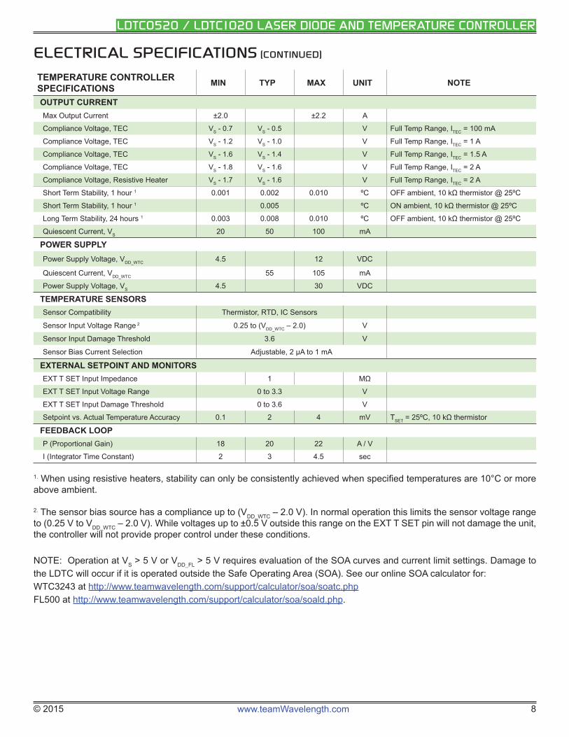
ELECTRICAL SPECIFICATIONS (CONTINUED)
TEMPERATURE CONTROLLER SPECIFICATIONS MIN TYP MAX UNIT NOTE
OUTPUT CURRENTMax Output Current ±2.0 ±2.2 A
Compliance Voltage, TEC VS - 0.7 VS - 0.5 V Full Temp Range, ITEC = 100 mA
Compliance Voltage, TEC VS - 1.2 VS - 1.0 V Full Temp Range, ITEC = 1 A
Compliance Voltage, TEC VS - 1.6 VS - 1.4 V Full Temp Range, ITEC = 1.5 A
Compliance Voltage, TEC VS - 1.8 VS - 1.6 V Full Temp Range, ITEC = 2 A
Compliance Voltage, Resistive Heater VS - 1.7 VS - 1.6 V Full Temp Range, ITEC = 2 A
Short Term Stability, 1 hour 1 0.001 0.002 0.010 ºC OFF ambient, 10 kΩ thermistor @ 25ºC
Short Term Stability, 1 hour 1 0.005 ºC ON ambient, 10 kΩ thermistor @ 25ºC
Long Term Stability, 24 hours 1 0.003 0.008 0.010 ºC OFF ambient, 10 kΩ thermistor @ 25ºC
Quiescent Current, VS 20 50 100 mA
POWER SUPPLYPower Supply Voltage, VDD_WTC 4.5 12 VDC
Quiescent Current, VDD_WTC 55 105 mA
Power Supply Voltage, VS 4.5 30 VDC
TEMPERATURE SENSORSSensor Compatibility Thermistor, RTD, IC Sensors
Sensor Input Voltage Range 2 0.25 to (VDD_WTC – 2.0) V
Sensor Input Damage Threshold 3.6 V
Sensor Bias Current Selection Adjustable, 2 μA to 1 mA
EXTERNAL SETPOINT AND MONITORSEXT T SET Input Impedance 1 MΩ
EXT T SET Input Voltage Range 0 to 3.3 V
EXT T SET Input Damage Threshold 0 to 3.6 V
Setpoint vs. Actual Temperature Accuracy 0.1 2 4 mV TSET = 25ºC, 10 kΩ thermistor
FEEDBACK LOOPP (Proportional Gain) 18 20 22 A / V
I (Integrator Time Constant) 2 3 4.5 sec
1. When using resistive heaters, stability can only be consistently achieved when specifi ed temperatures are 10°C or more above ambient.
2. The sensor bias source has a compliance up to (VDD_WTC – 2.0 V). In normal operation this limits the sensor voltage range to (0.25 V to VDD_WTC – 2.0 V). While voltages up to ±0.5 V outside this range on the EXT T SET pin will not damage the unit, the controller will not provide proper control under these conditions.
NOTE: Operation at VS > 5 V or VDD_FL > 5 V requires evaluation of the SOA curves and current limit settings. Damage to the LDTC will occur if it is operated outside the Safe Operating Area (SOA). See our online SOA calculator for: WTC3243 at http://www.teamwavelength.com/support/calculator/soa/soatc.php FL500 at http://www.teamwavelength.com/support/calculator/soa/soald.php.
© 2015 www.teamWavelength.com 9
LDTC0520 / LDTC1020 LASER DIODE AND TEMPERATURE CONTROLLER
THEORY OF OPERATIONThe LDTC Laser Diode Driver and Temperature Controller combines Wavelength’s proprietary FL500 and highly stable WTC3243 in one compact module.
The LDTC0520 employs a single FL500 laser diode control chip; the LDTC1020 parallels two FL500 chips. The current source continually monitors the actual output current, compares it to the setpoint, and adjusts the current if there is a difference between the two signals.
It may be useful to remember that you do not directly set the drive current setpoint; instead, you adjust a voltage signal that represents the output current. The setpoint voltage is controlled by the onboard trimpot or by an external input.
As current is driven through the load, there is a voltage drop across the load because of the impedance. As the current increases, the voltage drop may increase to the point that it reaches the Compliance Voltage limit of the current source. Once that occurs the current source is no longer able to increase the current driven to the load even if you increase the setpoint.
The LDTC laser driver includes features that help protect your laser and make the driver more versatile in a wide array of applications:
• The current limit is set by an onboard trimpot and protects the laser from over-current conditions. The current limit circuit is designed to avoid overshoot, ringing, or saturating the control elements, and recovers from limit events without phase shifts or inversions.
• Slow-start delays the current ramp by 100 msec, and then ramps the current to setpoint at a rate of 15 mA / msec.
• The photodiode feedback control loop allows for Constant Power operation whereby the driver adjusts the laser forward current in order to maintain a constant photodiode current.
• Brownout protection switches off the laser diode drive current if VDD_FL drops below 2.7 VDC.
The WTC3243 delivers bidirectional current to a Peltier Effect thermoelectric cooler, or unidirectional current to a resistive heater. The controller adjusts the output current in order to change the temperature of the sensor that is connected to the thermal load. The goal is to make the voltage across the sensor match the setpoint voltage, and then keep them equal in spite of changes to ambient conditions and variations in thermal load.
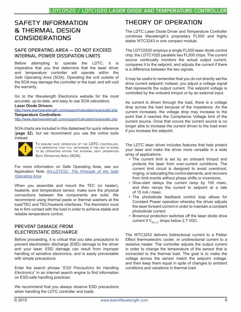
SAFETY INFORMATION & THERMAL DESIGN CONSIDERATIONS
SAFE OPERATING AREA — DO NOT EXCEED INTERNAL POWER DISSIPATION LIMITS
Before attempting to operate the LDTC, it is imperative that you fi rst determine that the laser driver and temperature controller will operate within the Safe Operating Area (SOA). Operating the unit outside of the SOA may damage the controller or the load, and will void the warranty.
Go to the Wavelength Electronics website for the most accurate, up-to-date, and easy to use SOA calculators:Laser Diode Drivers:http://www.teamwavelength.com/support/calculator/soa/soald.phphttp://www.teamwavelength.com/support/calculator/soa/soald.phpTemperature Controllers:Temperature Controllers:http://www.teamwavelength.com/support/calculator/soa/soatc.phphttp://www.teamwavelength.com/support/calculator/soa/soatc.php
SOA charts are included in this datasheet for quick reference (page 22), but we recommend you use the online tools instead.
TO ENSURE SAFE OPERATION OF THE LDTC CONTROLLER, IT IS IMPERATIVE THAT YOU DETERMINE IF THE UNIT IS GOING TO BE OPERATING WITHIN THE INTERNAL HEAT DISSIPATION SAFE OPERATING AREA (SOA).
For more information on Safe Operating Area, see our Application Note AN-LDTC01: The Principle of the Safe Operating Area.
When you assemble and mount the TEC (or heater), heatsink, and temperature sensor, make sure the physical connections between the components are solid. We recommend using thermal paste or thermal washers at the load/TEC and TEC / heatsink interfaces. The thermistor must be in fi rm contact with the load in order to achieve stable and reliable temperature control.
PREVENT DAMAGE FROM ELECTROSTATIC DISCHARGE
Before proceeding, it is critical that you take precautions to prevent electrostatic discharge (ESD) damage to the driver and your laser. ESD damage can result from improper handling of sensitive electronics, and is easily preventable with simple precautions.
Enter the search phrase “ESD Precautions for Handling Electronics” in an internet search engine to fi nd information on ESD-safe handling practices.
We recommend that you always observe ESD precautions when handling the LDTC controller and loads.
!
© 2015 www.teamWavelength.com 10
LDTC0520 / LDTC1020 LASER DIODE AND TEMPERATURE CONTROLLER
The controller measures the load temperature by driving a current through the temperature sensor and measuring the voltage drop across it. Similarly to the laser driver, you do not directly adjust the setpoint on the temperature controller; rather, you adjust a voltage signal that represents the sensor voltage at the desired temperature setpoint. The controller continuously compares the setpoint voltage and the actual sensor voltage. If there is a difference between the two signals the controller adjusts the output current—thereby driving the TEC or heater to change temperature—until the difference is zero.
Once the actual sensor voltage equals the setpoint voltage, the controller makes minor adjustments to the output current in order to keep the difference at zero.
The controller includes features that help protect the load from damage, and also make it more versatile in a wide array of applications.
• Independent heating and cooling current limits to protect from thermal runaway situations.
• The temperature setpoint can be adjusted with the onboard trimpot or by an external voltage signal.
• Control loop: the controller employs a smart Proportional-Integrating control loop to adjust the drive current. The proportional term is user-adjustable, and when properly confi gured will quickly settle the load to temperature with minimal overshoot and ringing.
OPERATING INSTRUCTIONS -- TEMPERATURE CONTROLLERThese instructions are written for the most common application of the LDTCxx20 Controllers: driving a laser diode, and controlling a Peltier-type thermoelectric cooler with a 10 kΩ thermistor sensor. We recommend you read and completely understand these instructions before proceeding with wiring the controller. Information for other confi gurations is also included in the technical support section on page 17.
Wavelength recommends confi guring the temperature controller before confi guring the laser diode driver. Additionally, we recommend using test loads to simulate the thermistor, TEC or heater, laser diode, and photodiode. Schematics for test loads are presented in Figure 6 and Figure 7 on page 4.
These instructions detail the steps necessary to confi gure the current limits for the temperature controller using a test load. Once that is done, the controller is reconfi gured with the thermal load and sensor for your application. Then the laser driver is confi gured with a test load. Finally, the laser diode is connected and the LDTCxx20 is ready to enter regular service.
!MAKE CERTAIN THE OUTPUT LEADS ARE NOT SHORTED. IF THE LASER OUTPUT OR TEMPERATURE CONTROLLER OUTPUT LEADS ARE SHORTED DURING SETUP, CURRENT WILL FLOW AND THE LDTC MAY BE DAMAGED.
Wavelength recommends that initial wiring and confi guration of the LDTCxx20 is performed with test loads in place of the TEC and thermistor. Using test loads reduces the risk of damaging expensive components, and can make the confi guration process simpler.
The confi guration sequence is as follows:• Connect the power supplies and test loads• Set the current limit• Replace the test loads with your temperature sensor
and TEC• Confi gure for external or local (internal) control• Adjust the temperature setpoint and monitor the
controller
© 2015 www.teamWavelength.com 11
LDTC0520 / LDTC1020 LASER DIODE AND TEMPERATURE CONTROLLER
NECESSARY EQUIPMENT
The following equipment is the minimum necessary to confi gure the LDTC for basic operation.
• LDTC controller• Power supplies; choose low-noise power supplies for
the best performance and refer to page 11 for details on each power supply requirement.• VDD_FL – power supply for the laser driver electronics
and the laser diode• VDD_WTC – power supply for the temperature controller
electronics• VS – power supply to drive the TEC
• Digital multimeter, 4-½ digit resolution recommended• Laser diode• Thermistor or other temperature sensor• Peltier-type thermoelectric module, or resistive heater,
heatsink for the temperature-controlled load, mounting hardware, thermal washers or paste
• Connecting wires
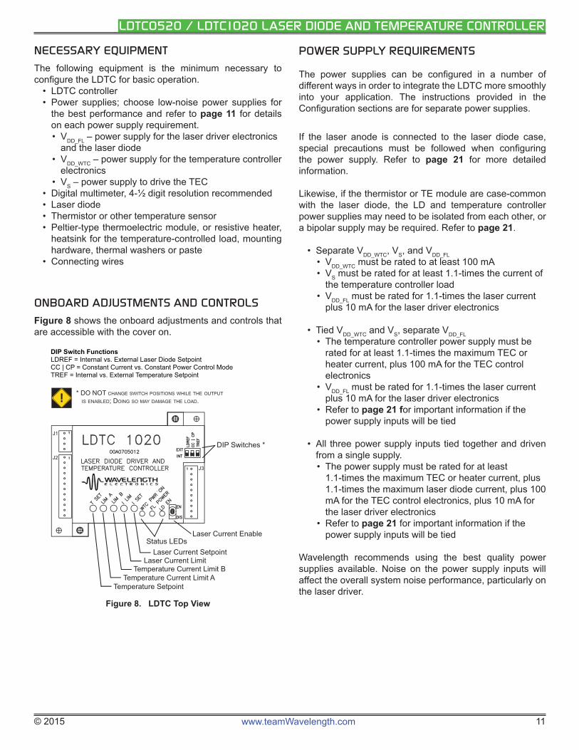
ONBOARD ADJUSTMENTS AND CONTROLS
Figure 8 shows the onboard adjustments and controls that are accessible with the cover on.
J1
J2
J3
Status LEDsLaser Current Enable
Laser Current SetpointLaser Current Limit
Temperature Current Limit B
Temperature SetpointTemperature Current Limit A
DIP Switches *
DIP Switch FunctionsLDREF = Internal vs. External Laser Diode SetpointCC | CP = Constant Current vs. Constant Power Control ModeTREF = Internal vs. External Temperature Setpoint
* DO NOT CHANGE SWITCH POSITIONS WHILE THE OUTPUT
IS ENABLED; DOING SO MAY DAMAGE THE LOAD.!
Figure 8. LDTC Top View
POWER SUPPLY REQUIREMENTS
The power supplies can be confi gured in a number of different ways in order to integrate the LDTC more smoothly into your application. The instructions provided in the Confi guration sections are for separate power supplies.
If the laser anode is connected to the laser diode case, special precautions must be followed when confi guring the power supply. Refer to page 21 for more detailed information.
Likewise, if the thermistor or TE module are case-common with the laser diode, the LD and temperature controller power supplies may need to be isolated from each other, or a bipolar supply may be required. Refer to page 21.
• Separate VDD_WTC, VS, and VDD_FL• VDD_WTC must be rated to at least 100 mA• VS must be rated for at least 1.1-times the current of
the temperature controller load• VDD_FL must be rated for 1.1-times the laser current
plus 10 mA for the laser driver electronics
• Tied VDD_WTC and VS, separate VDD_FL • The temperature controller power supply must be
rated for at least 1.1-times the maximum TEC or heater current, plus 100 mA for the TEC control electronics
• VDD_FL must be rated for 1.1-times the laser current plus 10 mA for the laser driver electronics
• Refer to page 21 for important information if the power supply inputs will be tied
• All three power supply inputs tied together and driven from a single supply. • The power supply must be rated for at least
1.1-times the maximum TEC or heater current, plus 1.1-times the maximum laser diode current, plus 100 mA for the TEC control electronics, plus 10 mA for the laser driver electronics
• Refer to page 21 for important information if the power supply inputs will be tied
Wavelength recommends using the best quality power supplies available. Noise on the power supply inputs will affect the overall system noise performance, particularly on the laser driver.
© 2015 www.teamWavelength.com 12
LDTC0520 / LDTC1020 LASER DIODE AND TEMPERATURE CONTROLLER
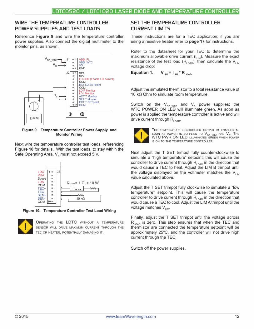
WIRE THE TEMPERATURE CONTROLLER POWER SUPPLIES AND TEST LOADS
Reference Figure 9 and wire the temperature controller power supplies. Also connect the digital multimeter to the monitor pins, as shown.
VDD_FLVDD_WTCVSGND
SP1SP2LD SHD (Enable LD current)COMEXT LD SETpointCOMLD P MonitorLD I MonitorACT T MonitorSET T MonitorEXT T SETpointCOM
J1
J2
VDD_WTC
VS
1
1
4
12
DMM
Figure 9. Temperature Controller Power Supply and Monitor Wiring
Next wire the temperature controller test loads, referencing Figure 10 for details. With the test loads, to stay within the Safe Operating Area, VS must not exceed 5 V.
LDCPDASpareLDACOMTEC+TEC-SEN+SEN-COM
J31
10
RLOAD
IMETER
Figure 10. Temperature Controller Test Load Wiring
!OPERATING THE LDTC WITHOUT A TEMPERATURE SENSOR WILL DRIVE MAXIMUM CURRENT THROUGH THE TEC OR HEATER, POTENTIALLY DAMAGING IT.
SET THE TEMPERATURE CONTROLLER CURRENT LIMITS
These instructions are for a TEC application; if you are using a resistive heater refer to page 17 for instructions.
Refer to the datasheet for your TEC to determine the maximum allowable drive current (ILIM). Measure the exact resistance of the test load (RLOAD), then calculate the VLIM voltage drop: Equation 1. VLIM = ILIM * RLOAD
Adjust the simulated thermistor to a total resistance value of 10 kΩ Ohm to simulate room temperature.
Switch on the VDD_WTC and VS power supplies; the WTC POWER ON LED will illuminate green. As soon as power is applied the temperature controller is active and will drive current through RLOAD.
!THE TEMPERATURE CONTROLLER OUTPUT IS ENABLED AS SOON AS POWER IS SUPPLIED TO VDD_WTC AND VS. THE WTC PWR ON LED ILLUMINATES GREEN WHEN POWER IS ON TO THE TEMPERATURE CONTROLLER.
Next adjust the T SET trimpot fully counter-clockwise to simulate a “high temperature” setpoint; this will cause the controller to drive current through RLOAD in the direction that would cause a TEC to heat. Adjust the LIM B trimpot until the voltage displayed on the voltmeter matches the VLIM value calculated above.
Adjust the T SET trimpot fully clockwise to simulate a “low temperature” setpoint. This will cause the temperature controller to drive current through RLOAD in the direction that would cause a TEC to cool. Adjust the LIM A trimpot until the voltage matches VLIM.
Finally, adjust the T SET trimpot until the voltage across RLOAD is zero. This step ensures that when the TEC and thermistor are connected the temperature setpoint will be approximately 25ºC, and the controller will not drive high current through the TEC.
Switch off the power supplies.
© 2015 www.teamWavelength.com 13
LDTC0520 / LDTC1020 LASER DIODE AND TEMPERATURE CONTROLLER
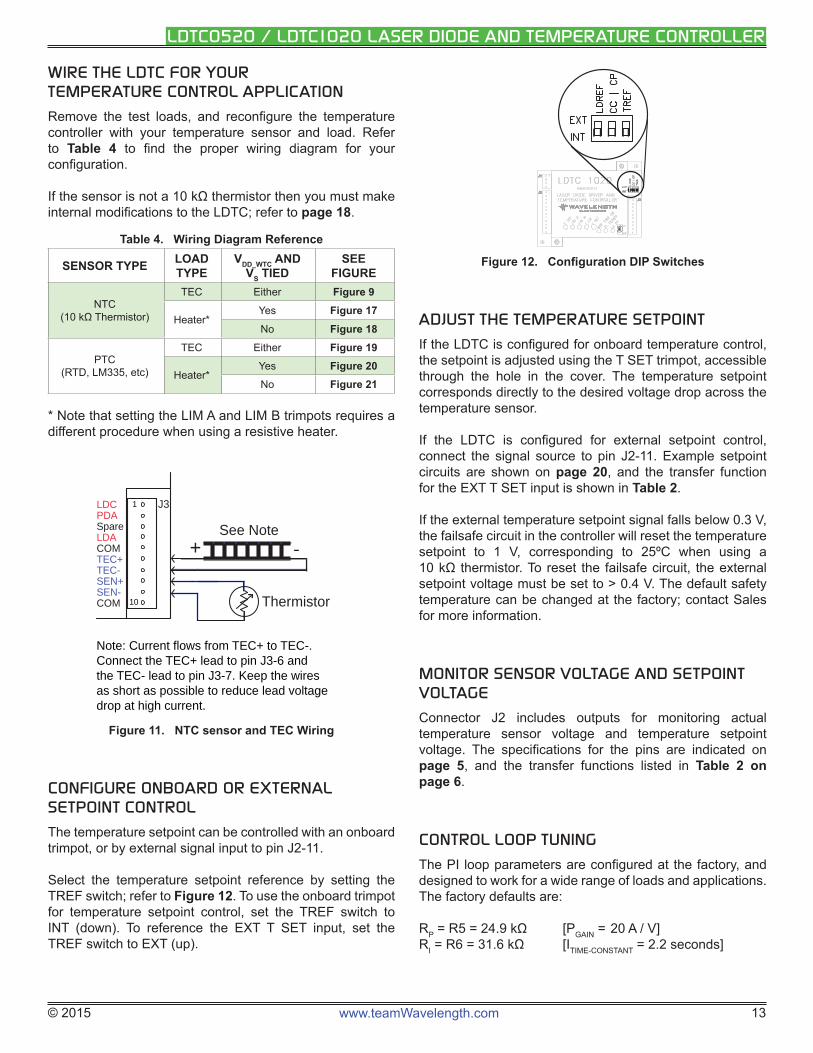
WIRE THE LDTC FOR YOURTEMPERATURE CONTROL APPLICATION
Remove the test loads, and reconfi gure the temperature controller with your temperature sensor and load. Refer to Table 4 to fi nd the proper wiring diagram for your confi guration.
If the sensor is not a 10 kΩ thermistor then you must make internal modifi cations to the LDTC; refer to page 18.
Table 4. Wiring Diagram Reference
SENSOR TYPE LOAD TYPE
VDD_WTC AND VS TIED
SEE FIGURE
NTC(10 kΩ Thermistor)
TEC Either Figure 9
Heater*Yes Figure 17
No Figure 18
PTC (RTD, LM335, etc)
TEC Either Figure 19
Heater*Yes Figure 20No Figure 21
* Note that setting the LIM A and LIM B trimpots requires a different procedure when using a resistive heater.
LDCPDASpareLDACOMTEC+TEC-SEN+SEN-COM
J3
See Note
Thermistor
1
10
-+
Note: Current flows from TEC+ to TEC-. Connect the TEC+ lead to pin J3-6 and the TEC- lead to pin J3-7. Keep the wires as short as possible to reduce lead voltage drop at high current.
Figure 11. NTC sensor and TEC Wiring
CONFIGURE ONBOARD OR EXTERNAL SETPOINT CONTROL
The temperature setpoint can be controlled with an onboard trimpot, or by external signal input to pin J2-11.
Select the temperature setpoint reference by setting the TREF switch; refer to Figure 12. To use the onboard trimpot for temperature setpoint control, set the TREF switch to INT (down). To reference the EXT T SET input, set the TREF switch to EXT (up).
J1J1
J2J2
J3J3
Figure 12. Confi guration DIP Switches
ADJUST THE TEMPERATURE SETPOINT
If the LDTC is confi gured for onboard temperature control, the setpoint is adjusted using the T SET trimpot, accessible through the hole in the cover. The temperature setpoint corresponds directly to the desired voltage drop across the temperature sensor.
If the LDTC is confi gured for external setpoint control, connect the signal source to pin J2-11. Example setpoint circuits are shown on page 20, and the transfer function for the EXT T SET input is shown in Table 2.
If the external temperature setpoint signal falls below 0.3 V, the failsafe circuit in the controller will reset the temperature setpoint to 1 V, corresponding to 25ºC when using a 10 kΩ thermistor. To reset the failsafe circuit, the external setpoint voltage must be set to > 0.4 V. The default safety temperature can be changed at the factory; contact Sales for more information.
MONITOR SENSOR VOLTAGE AND SETPOINT VOLTAGE
Connector J2 includes outputs for monitoring actual temperature sensor voltage and temperature setpoint voltage. The specifi cations for the pins are indicated on page 5, and the transfer functions listed in Table 2 on page 6.
CONTROL LOOP TUNING
The PI loop parameters are confi gured at the factory, and designed to work for a wide range of loads and applications. The factory defaults are:
RP = R5 = 24.9 kΩ [PGAIN = 20 A / V]RI = R6 = 31.6 kΩ [ITIME-CONSTANT = 2.2 seconds]
© 2015 www.teamWavelength.com 14
LDTC0520 / LDTC1020 LASER DIODE AND TEMPERATURE CONTROLLER
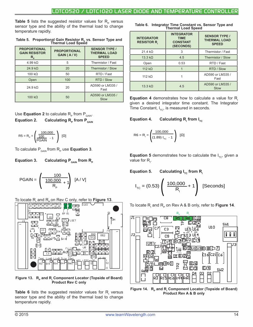
Table 5 lists the suggested resistor values for RP versus sensor type and the ability of the thermal load to change temperature rapidly.
Table 5. Proportional Gain Resistor RP vs. Sensor Type and Thermal Load Speed
PROPORTIONAL GAIN RESISTOR
RP
PROPORTIONAL GAIN ( A / V)
SENSOR TYPE / THERMAL LOAD
SPEED4.99 kΩ 5 Thermistor / Fast
24.9 kΩ 20 Thermistor / Slow
100 kΩ 50 RTD / Fast
Open 100 RTD / Slow
24.9 kΩ 20 AD590 or LM335 / Fast
100 kΩ 50 AD590 or LM335 / Slow
Use Equation 2 to calculate RP from PGAIN. Equation 2. Calculating RP from PGAIN
R5 = RP = ( 100,000
) [ ]
100 - 1 PGAIN
To calculate PGAIN from RP use Equation 3.
Equation 3. Calculating PGAIN from RP
PGAIN = ( 100
) [A / V]
100,000 + 1 RP
To locate RI and RP on Rev C only, refer to Figure 13.
Figure 13. RP and RI Component Locator (Topside of Board) Product Rev C only
Table 6 lists the suggested resistor values for RI versus sensor type and the ability of the thermal load to change temperature rapidly.
Table 6. Integrator Time Constant vs. Sensor Type and Thermal Load Speed
INTEGRATOR RESISTOR RI
INTEGRATOR TIME
CONSTANT (SECONDS)
SENSOR TYPE / THERMAL LOAD
SPEED
21.4 kΩ 3 Thermistor / Fast
13.3 kΩ 4.5 Thermistor / Slow
Open 0.53 RTD / Fast
112 kΩ 1 RTD / Slow
112 kΩ 1 AD590 or LM335 / Fast
13.3 kΩ 4.5 AD590 or LM335 / Slow
Equation 4 demonstrates how to calculate a value for RI given a desired integrator time constant. The Integrator Time Constant, ITC, is measured in seconds.
Equation 4. Calculating RI from ITC
R6 = RI = ( 100,000
) [ ] (1.89) ITC
- 1
Equation 5 demonstrates how to calculate the ITC, given a value for RI.
Equation 5. Calculating ITC from RI
ITC = (0.53) ( 100,000 + 1) [Seconds]
RI
To locate RI and RP on Rev A & B only, refer to Figure 14.
Figure 14. RP and RI Component Locator (Topside of Board) Product Rev A & B only
RP RI
© 2015 www.teamWavelength.com 15
LDTC0520 / LDTC1020 LASER DIODE AND TEMPERATURE CONTROLLER
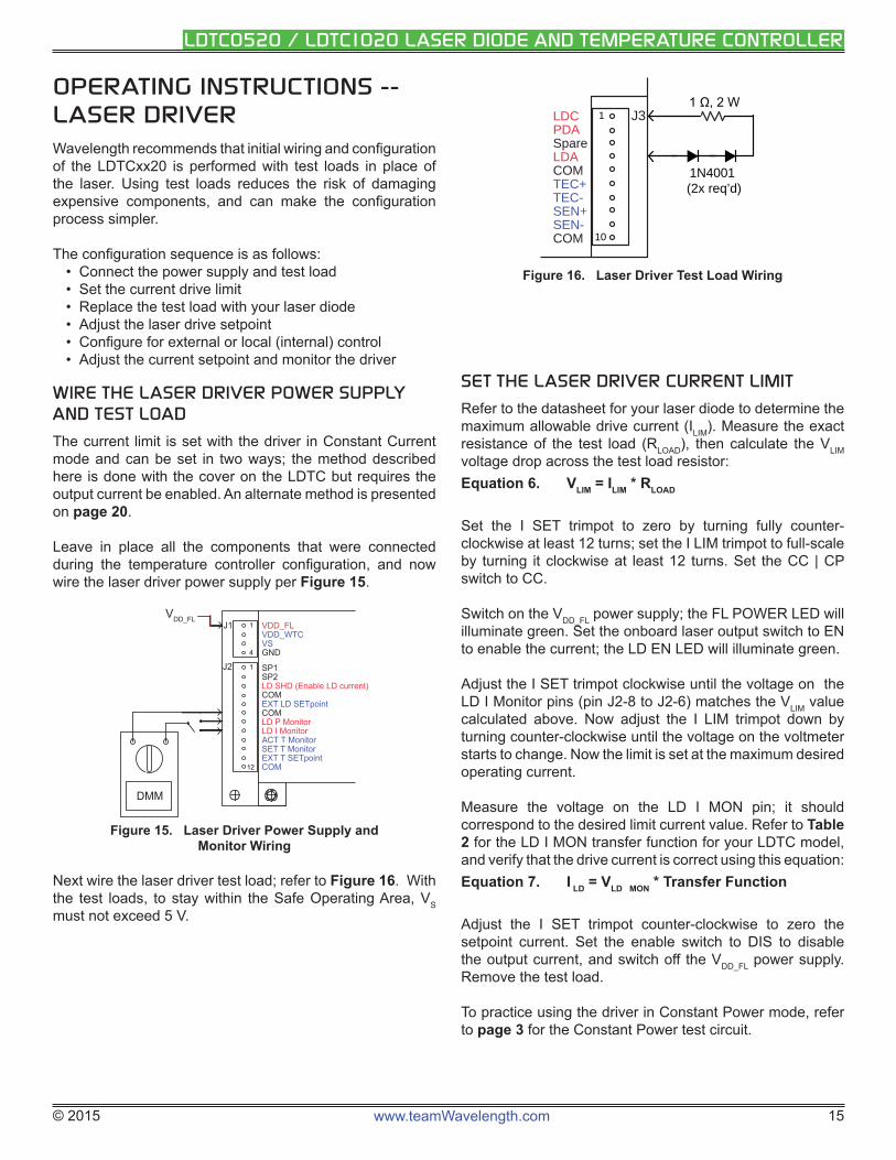
OPERATING INSTRUCTIONS -- LASER DRIVERWavelength recommends that initial wiring and confi guration of the LDTCxx20 is performed with test loads in place of the laser. Using test loads reduces the risk of damaging expensive components, and can make the confi guration process simpler.
The confi guration sequence is as follows:• Connect the power supply and test load• Set the current drive limit• Replace the test load with your laser diode• Adjust the laser drive setpoint• Confi gure for external or local (internal) control• Adjust the current setpoint and monitor the driver
WIRE THE LASER DRIVER POWER SUPPLY AND TEST LOAD
The current limit is set with the driver in Constant Current mode and can be set in two ways; the method described here is done with the cover on the LDTC but requires the output current be enabled. An alternate method is presented on page 20.
Leave in place all the components that were connected during the temperature controller confi guration, and now wire the laser driver power supply per Figure 15.
VDD_FLVDD_WTCVSGND
SP1SP2LD SHD (Enable LD current)COMEXT LD SETpointCOMLD P MonitorLD I MonitorACT T MonitorSET T MonitorEXT T SETpointCOM
J1
J2
VDD_FL1
1
4
12
DMM
Figure 15. Laser Driver Power Supply and Monitor Wiring
Next wire the laser driver test load; refer to Figure 16. With the test loads, to stay within the Safe Operating Area, VS must not exceed 5 V.
LDCPDASpareLDACOMTEC+TEC-SEN+SEN-COM
J31
10
1N4001 (2x req’d)
Figure 16. Laser Driver Test Load Wiring
SET THE LASER DRIVER CURRENT LIMIT
Refer to the datasheet for your laser diode to determine the maximum allowable drive current (ILIM). Measure the exact resistance of the test load (RLOAD), then calculate the VLIM voltage drop across the test load resistor: Equation 6. VLIM = ILIM * RLOAD
Set the I SET trimpot to zero by turning fully counter-clockwise at least 12 turns; set the I LIM trimpot to full-scale by turning it clockwise at least 12 turns. Set the CC | CP switch to CC.
Switch on the VDD_FL power supply; the FL POWER LED will illuminate green. Set the onboard laser output switch to EN to enable the current; the LD EN LED will illuminate green.
Adjust the I SET trimpot clockwise until the voltage on the LD I Monitor pins (pin J2-8 to J2-6) matches the VLIM value calculated above. Now adjust the I LIM trimpot down by turning counter-clockwise until the voltage on the voltmeter starts to change. Now the limit is set at the maximum desired operating current.
Measure the voltage on the LD I MON pin; it should correspond to the desired limit current value. Refer to Table 2 for the LD I MON transfer function for your LDTC model, and verify that the drive current is correct using this equation: Equation 7. I LD = VLD MON * Transfer Function
Adjust the I SET trimpot counter-clockwise to zero the setpoint current. Set the enable switch to DIS to disable the output current, and switch off the VDD_FL power supply. Remove the test load.
To practice using the driver in Constant Power mode, refer to page 3 for the Constant Power test circuit.
© 2015 www.teamWavelength.com 16
LDTC0520 / LDTC1020 LASER DIODE AND TEMPERATURE CONTROLLER
WIRE THE LDTC FOR YOUR LASER DRIVER APPLICATION
If you are comfortable with the operation of the LDTC laser driver, connect your laser diode per Figure 2 on page 2. This fi gure also shows how to connect the optional external enable switch and external setpoint signal source. Example setpoint circuits are shown on page 20. The transfer function for the EXT LD SET input is shown in Table 2.
! DO NOT INSERT OR REMOVE THE LASER DIODE FROM THE CIRCUIT WHILE POWER IS APPLIED TO THE LDTC. THE LASER DIODE MAY BE DAMAGED OR DESTROYED.
SET CONSTANT POWER OR CONSTANT CURRENT CONTROL MODE
Refer to Figure 12, and set the mode switch for Constant Current or Constant Power mode: the mode switch is the center DIP switch, labeled “CC | CP”. For Constant Current mode operation, set the switch to INT (down); for Constant Power mode, set the switch to EXT (up).
! DO NOT ADJUST THE CC | CP SWITCH WHILE THE OUTPUT IS ENABLED AND DRIVING A LASER DIODE. THE LASER DIODE MAY BE DAMAGED OR DESTROYED.
In CC mode, the setpoint voltage correlates directly to the laser diode current. In CP mode the setpoint correlates to the photodiode feedback current. See Table 2 on page 6 for the transfer functions for CC and CP mode.
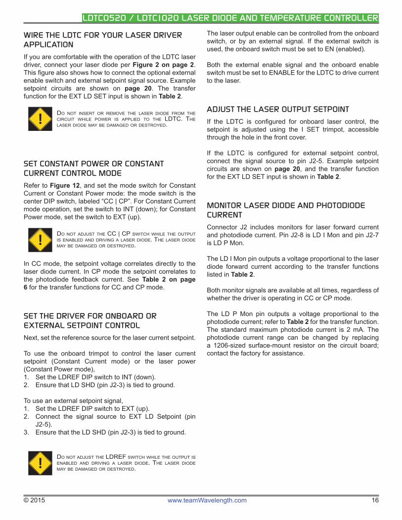
SET THE DRIVER FOR ONBOARD OR EXTERNAL SETPOINT CONTROL
Next, set the reference source for the laser current setpoint.
To use the onboard trimpot to control the laser current setpoint (Constant Current mode) or the laser power (Constant Power mode),1. Set the LDREF DIP switch to INT (down).2. Ensure that LD SHD (pin J2-3) is tied to ground.
To use an external setpoint signal,1. Set the LDREF DIP switch to EXT (up).2. Connect the signal source to EXT LD Setpoint (pin
J2-5).3. Ensure that the LD SHD (pin J2-3) is tied to ground.
! DO NOT ADJUST THE LDREF SWITCH WHILE THE OUTPUT IS ENABLED AND DRIVING A LASER DIODE. THE LASER DIODE MAY BE DAMAGED OR DESTROYED.
The laser output enable can be controlled from the onboard switch, or by an external signal. If the external switch is used, the onboard switch must be set to EN (enabled).
Both the external enable signal and the onboard enable switch must be set to ENABLE for the LDTC to drive current to the laser.
ADJUST THE LASER OUTPUT SETPOINT
If the LDTC is confi gured for onboard laser control, the setpoint is adjusted using the I SET trimpot, accessible through the hole in the front cover.
If the LDTC is confi gured for external setpoint control, connect the signal source to pin J2-5. Example setpoint circuits are shown on page 20, and the transfer function for the EXT LD SET input is shown in Table 2.
MONITOR LASER DIODE AND PHOTODIODE CURRENT
Connector J2 includes monitors for laser forward current and photodiode current. Pin J2-8 is LD I Mon and pin J2-7 is LD P Mon.
The LD I Mon pin outputs a voltage proportional to the laser diode forward current according to the transfer functions listed in Table 2.
Both monitor signals are available at all times, regardless of whether the driver is operating in CC or CP mode.
The LD P Mon pin outputs a voltage proportional to the photodiode current; refer to Table 2 for the transfer function. The standard maximum photodiode current is 2 mA. The photodiode current range can be changed by replacing a 1206-sized surface-mount resistor on the circuit board; contact the factory for assistance.
© 2015 www.teamWavelength.com 17
LDTC0520 / LDTC1020 LASER DIODE AND TEMPERATURE CONTROLLER
ADDITIONAL TECHNICAL INFORMATIONThis section includes useful technical information on these topics:
• Set the Current Limit When Using Resistive Heaters• Wire the LDTC Temperature Controller, Alternate
Applications• Set the Sensor Bias Current Resistor• Use The LM335• Use The AD590• Adjust Sensor Gain• External Setpoint Circuits• An Alternate Method for Setting the
Laser Driver Current Limit• Safely Tie the Power Supply Inputs• Safe Operating Area Calculation
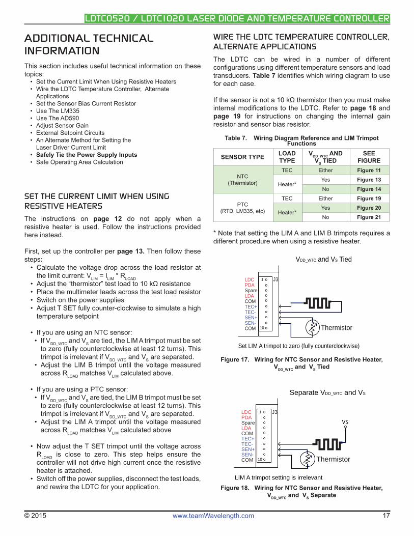
SET THE CURRENT LIMIT WHEN USING RESISTIVE HEATERS
The instructions on page 12 do not apply when a resistive heater is used. Follow the instructions provided here instead.
First, set up the controller per page 13. Then follow these steps:
• Calculate the voltage drop across the load resistor at the limit current: VLIM = ILIM * RLOAD
• Adjust the “thermistor” test load to 10 kΩ resistance• Place the multimeter leads across the test load resistor• Switch on the power supplies• Adjust T SET fully counter-clockwise to simulate a high
temperature setpoint
• If you are using an NTC sensor:• If VDD_WTC and VS are tied, the LIM A trimpot must be set
to zero (fully counterclockwise at least 12 turns). This trimpot is irrelevant if VDD_WTC and VS are separated.
• Adjust the LIM B trimpot until the voltage measured across RLOAD matches VLIM calculated above.
• If you are using a PTC sensor:• If VDD_WTC and VS are tied, the LIM B trimpot must be set
to zero (fully counterclockwise at least 12 turns). This trimpot is irrelevant if VDD_WTC and VS are separated.
• Adjust the LIM A trimpot until the voltage measured across RLOAD matches VLIM calculated above
• Now adjust the T SET trimpot until the voltage across RLOAD is close to zero. This step helps ensure the controller will not drive high current once the resistive heater is attached.
• Switch off the power supplies, disconnect the test loads, and rewire the LDTC for your application.
WIRE THE LDTC TEMPERATURE CONTROLLER, ALTERNATE APPLICATIONS
The LDTC can be wired in a number of different confi gurations using different temperature sensors and load transducers. Table 7 identifi es which wiring diagram to use for each case.
If the sensor is not a 10 kΩ thermistor then you must make internal modifi cations to the LDTC. Refer to page 18 and page 19 for instructions on changing the internal gain resistor and sensor bias resistor.
Table 7. Wiring Diagram Reference and LIM Trimpot Functions
SENSOR TYPE LOAD TYPE
VDD_WTC AND VS TIED
SEE FIGURE
NTC(Thermistor)
TEC Either Figure 11
Heater*Yes Figure 13No Figure 14
PTC (RTD, LM335, etc)
TEC Either Figure 19
Heater*Yes Figure 20No Figure 21
* Note that setting the LIM A and LIM B trimpots requires a different procedure when using a resistive heater.
LDCPDASpareLDACOMTEC+TEC-SEN+SEN-COM
J3
Thermistor
1
10
VDD_WTC and VS Tied
Set LIM A trimpot to zero (fully counterclockwise)
Figure 17. Wiring for NTC Sensor and Resistive Heater, VDD_WTC and VS Tied
LDCPDASpareLDACOMTEC+TEC-SEN+SEN-COM
J3
Thermistor
1
10
VS
Separate VDD_WTC and VS
LIM A trimpot setting is irrelevant
Figure 18. Wiring for NTC Sensor and Resistive Heater, VDD_WTC and VS Separate
© 2015 www.teamWavelength.com 18
LDTC0520 / LDTC1020 LASER DIODE AND TEMPERATURE CONTROLLER
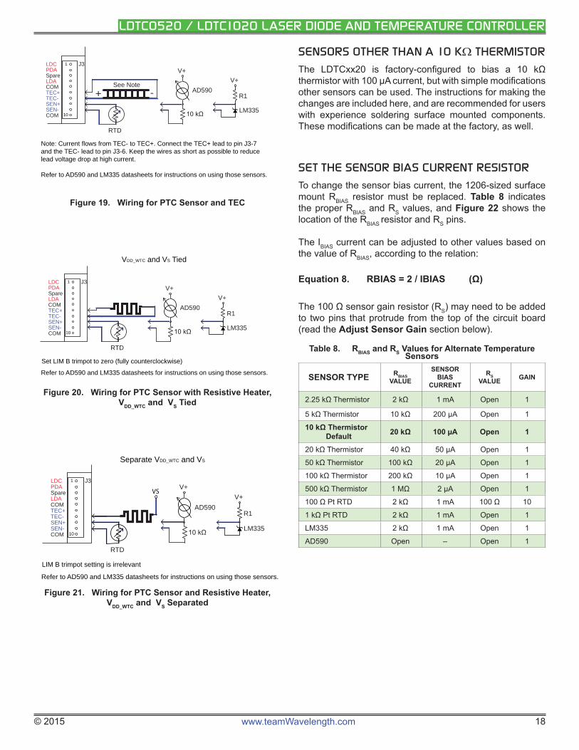
SENSORS OTHER THAN A 10 K THERMISTOR
The LDTCxx20 is factory-confi gured to bias a 10 kΩ thermistor with 100 μA current, but with simple modifi cations other sensors can be used. The instructions for making the changes are included here, and are recommended for users with experience soldering surface mounted components. These modifi cations can be made at the factory, as well.
SET THE SENSOR BIAS CURRENT RESISTOR
To change the sensor bias current, the 1206-sized surface mount RBIAS resistor must be replaced. Table 8 indicates the proper RBIAS and RS values, and Figure 22 shows the location of the RBIAS resistor and RS pins.
The IBIAS current can be adjusted to other values based on the value of RBIAS, according to the relation:
Equation 8. RBIAS = 2 / IBIAS (Ω)
The 100 Ω sensor gain resistor (RS) may need to be added to two pins that protrude from the top of the circuit board (read the Adjust Sensor Gain section below).
Table 8. RBIAS and RS Values for Alternate Temperature Sensors
SENSOR TYPE RBIAS VALUE
SENSOR BIAS
CURRENT
RS VALUE GAIN
2.25 kΩ Thermistor 2 kΩ 1 mA Open 1
5 kΩ Thermistor 10 kΩ 200 μA Open 1
10 kΩ ThermistorDefault 20 kΩ 100 μA Open 1
20 kΩ Thermistor 40 kΩ 50 μA Open 1
50 kΩ Thermistor 100 kΩ 20 μA Open 1
100 kΩ Thermistor 200 kΩ 10 μA Open 1
500 kΩ Thermistor 1 MΩ 2 μA Open 1
100 Ω Pt RTD 2 kΩ 1 mA 100 Ω 10
1 kΩ Pt RTD 2 kΩ 1 mA Open 1
LM335 2 kΩ 1 mA Open 1
AD590 Open – Open 1
LDCPDASpareLDACOMTEC+TEC-SEN+SEN-COM
J3
See Note
RTD
1
10
-+
Note: Current flows from TEC- to TEC+. Connect the TEC+ lead to pin J3-7 and the TEC- lead to pin J3-6. Keep the wires as short as possible to reduce lead voltage drop at high current.
Refer to AD590 and LM335 datasheets for instructions on using those sensors.
AD590
V+
LM335
R1
V+
Figure 19. Wiring for PTC Sensor and TEC
LDCPDASpareLDACOMTEC+TEC-SEN+SEN-COM
J31
10
RTD
VDD_WTC and VS Tied
Set LIM B trimpot to zero (fully counterclockwise)
AD590
V+
LM335
R1
V+
Refer to AD590 and LM335 datasheets for instructions on using those sensors.
Figure 20. Wiring for PTC Sensor with Resistive Heater, VDD_WTC and VS Tied
LDCPDASpareLDACOMTEC+TEC-SEN+SEN-COM
J31
10
VS
RTD
Separate VDD_WTC and VS
LIM B trimpot setting is irrelevant
Refer to AD590 and LM335 datasheets for instructions on using those sensors.
AD590
V+
LM335
R1
V+
Figure 21. Wiring for PTC Sensor and Resistive Heater, VDD_WTC and VS Separated
© 2015 www.teamWavelength.com 19
LDTC0520 / LDTC1020 LASER DIODE AND TEMPERATURE CONTROLLER
RBiasSensor Gain Resistor
Figure 22. Sensor Gain Resistor and Location of RBIAS — Rev C only
RBias
Sensor Gain Resistor
Figure 23. Sensor Gain Resistor and Location of RBIAS — Rev A & B only
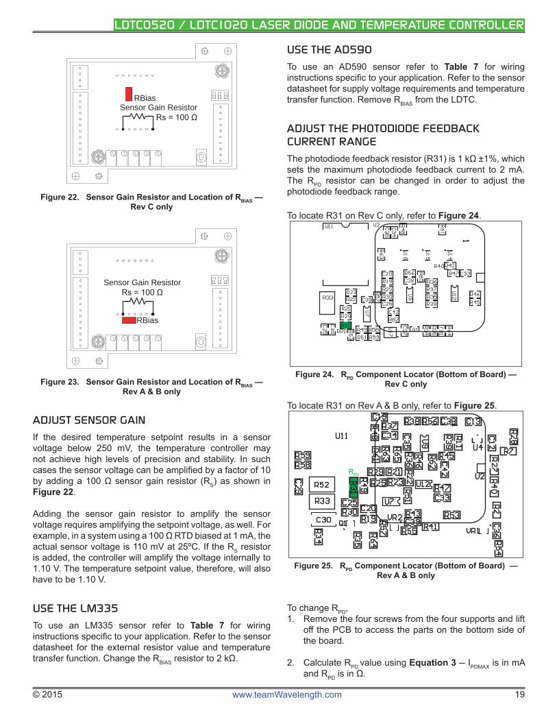
ADJUST SENSOR GAIN
If the desired temperature setpoint results in a sensor voltage below 250 mV, the temperature controller may not achieve high levels of precision and stability. In such cases the sensor voltage can be amplifi ed by a factor of 10 by adding a 100 Ω sensor gain resistor (RS) as shown in Figure 22.
Adding the sensor gain resistor to amplify the sensor voltage requires amplifying the setpoint voltage, as well. For example, in a system using a 100 Ω RTD biased at 1 mA, the actual sensor voltage is 110 mV at 25ºC. If the RS resistor is added, the controller will amplify the voltage internally to 1.10 V. The temperature setpoint value, therefore, will also have to be 1.10 V.
USE THE LM335
To use an LM335 sensor refer to Table 7 for wiring instructions specifi c to your application. Refer to the sensor datasheet for the external resistor value and temperature transfer function. Change the RBIAS resistor to 2 kΩ.
USE THE AD590
To use an AD590 sensor refer to Table 7 for wiring instructions specifi c to your application. Refer to the sensor datasheet for supply voltage requirements and temperature transfer function. Remove RBIAS from the LDTC.
ADJUST THE PHOTODIODE FEEDBACK CURRENT RANGE
The photodiode feedback resistor (R31) is 1 kΩ ±1%, which sets the maximum photodiode feedback current to 2 mA. The RPD resistor can be changed in order to adjust the photodiode feedback range.
To locate R31 on Rev C only, refer to Figure 24.
Figure 24. RPD Component Locator (Bottom of Board) — Rev C only
To locate R31 on Rev A & B only, refer to Figure 25.
RPD
Figure 25. RPD Component Locator (Bottom of Board) — Rev A & B only
To change RPD, 1. Remove the four screws from the four supports and lift
off the PCB to access the parts on the bottom side of the board.
2. Calculate RPD value using Equation 3 -- IPDMAX is in mA and RPD is in Ω.
© 2015 www.teamWavelength.com 20
LDTC0520 / LDTC1020 LASER DIODE AND TEMPERATURE CONTROLLER
Equation 3. Calculate RPD
IPDMAX = ( 2 )
RPD
3. Change R31 appropriately.
4. Replace thermal compound on the FL500(s) and reinstall PCB on the supports.
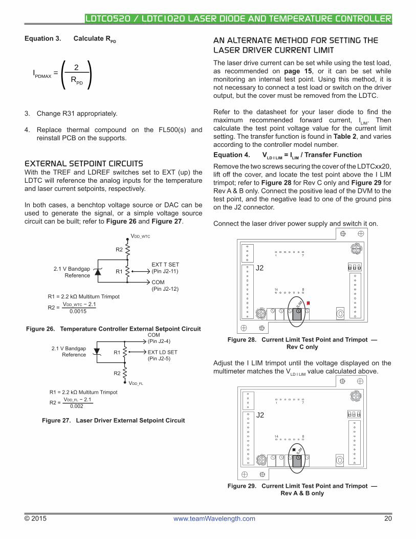
EXTERNAL SETPOINT CIRCUITSWith the TREF and LDREF switches set to EXT (up) the LDTC will reference the analog inputs for the temperature and laser current setpoints, respectively.
In both cases, a benchtop voltage source or DAC can be used to generate the signal, or a simple voltage source circuit can be built; refer to Figure 26 and Figure 27.
2.1 V BandgapReference
VDD_WTC
EXT T SET(Pin J2-11)
COM(Pin J2-12)
R2
R1
R1 = 2.2 kΩ Multiturn Trimpot
R2 = VDD_WTC − 2.10.0015
Figure 26. Temperature Controller External Setpoint Circuit
2.1 V BandgapReference
VDD_FL
COM(Pin J2-4)
EXT LD SET(Pin J2-5)
R1
R2
R1 = 2.2 kΩ Multiturn Trimpot
R2 = VDD_FL − 2.10.002
Figure 27. Laser Driver External Setpoint Circuit
AN ALTERNATE METHOD FOR SETTING THE LASER DRIVER CURRENT LIMIT
The laser drive current can be set while using the test load, as recommended on page 15, or it can be set while monitoring an internal test point. Using this method, it is not necessary to connect a test load or switch on the driver output, but the cover must be removed from the LDTC.
Refer to the datasheet for your laser diode to fi nd the maximum recommended forward current, ILIM. Then calculate the test point voltage value for the current limit setting. The transfer function is found in Table 2, and varies according to the controller model number.Equation 4. VLD I LIM = ILIM / Transfer FunctionRemove the two screws securing the cover of the LDTCxx20, lift off the cover, and locate the test point above the I LIM trimpot; refer to Figure 28 for Rev C only and Figure 29 for Rev A & B only. Connect the positive lead of the DVM to the test point, and the negative lead to one of the ground pins on the J2 connector.
Connect the laser driver power supply and switch it on.
ILIM
J2
Figure 28. Current Limit Test Point and Trimpot — Rev C only
Adjust the I LIM trimpot until the voltage displayed on the multimeter matches the VLD I LIM value calculated above.
ILIM
J2
Figure 29. Current Limit Test Point and Trimpot — Rev A & B only
© 2015 www.teamWavelength.com 21
LDTC0520 / LDTC1020 LASER DIODE AND TEMPERATURE CONTROLLER
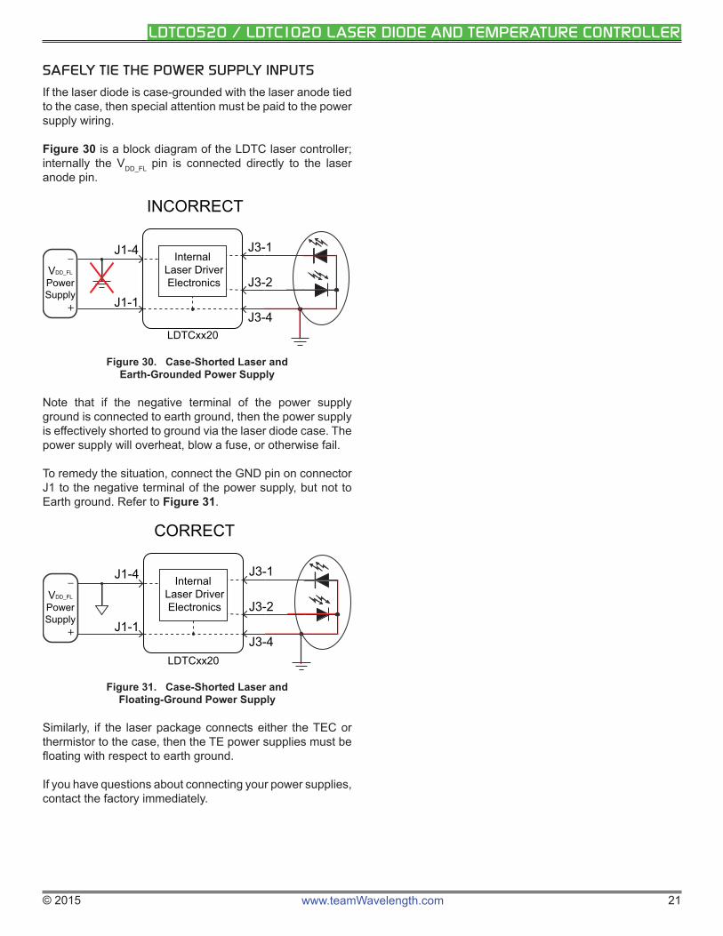
SAFELY TIE THE POWER SUPPLY INPUTS
If the laser diode is case-grounded with the laser anode tied to the case, then special attention must be paid to the power supply wiring.
Figure 30 is a block diagram of the LDTC laser controller; internally the VDD_FL pin is connected directly to the laser anode pin.
Internal Laser DriverElectronics
VDD_FL
PowerSupply
LDTCxx20
INCORRECT
J1-1
J3-1
J3-2
J3-4
J1-4
+
_
Figure 30. Case-Shorted Laser and Earth-Grounded Power Supply
Note that if the negative terminal of the power supply ground is connected to earth ground, then the power supply is effectively shorted to ground via the laser diode case. The power supply will overheat, blow a fuse, or otherwise fail.
To remedy the situation, connect the GND pin on connector J1 to the negative terminal of the power supply, but not to Earth ground. Refer to Figure 31.
Internal Laser DriverElectronics
LDTCxx20
J1-1
J3-1
J3-2
J3-4
J1-4
CORRECT
+
_
VDD_FL
PowerSupply
Figure 31. Case-Shorted Laser and Floating-Ground Power Supply
Similarly , if the laser package connects either the TEC or thermistor to the case, then the TE power supplies must be fl oating with respect to earth ground.
If you have questions about connecting your power supplies, contact the factory immediately.
© 2015 www.teamWavelength.com 22
LDTC0520 / LDTC1020 LASER DIODE AND TEMPERATURE CONTROLLER
3.0 4.0 5.0 6.0 7.0 8.0 9.0 10.0 11.0 12.00.00
0.05
0.10
0.15
0.20
0.25
0.30
0.35
0.40
0.45
0.50
Voltage (V)
Cur
rent
(A)
Load Line
IMAX
VDROP VDD_FL
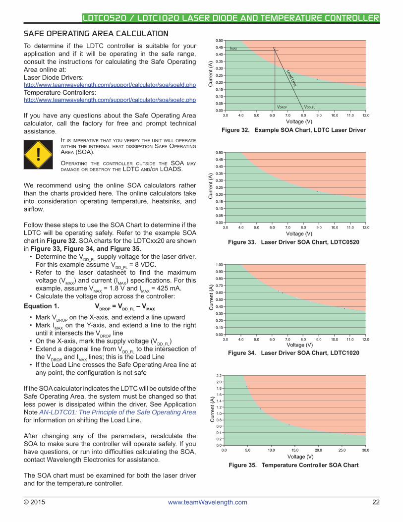
Figure 32. Example SOA Chart, LDTC Laser Driver
3.0 4.0 5.0 6.0 7.0 8.0 9.0 10.0 11.0 12.00.00
0.05
0.10
0.15
0.20
0.25
0.30
0.35
0.40
0.45
0.50
Voltage (V)
Cur
rent
(A)
Figure 33. Laser Driver SOA Chart, LDTC0520
3.0 4.0 5.0 6.0 7.0 8.0 9.0 10.0 11.0 12.00.00
0.10
0.20
0.30
0.40
0.50
0.60
0.70
0.80
0.90
1.00
Voltage (V)
Cur
rent
(A)
Figure 34. Laser Driver SOA Chart, LDTC1020
0.0 5.0 10.0 15.0 20.0 25.0 30.00.0
0.2
0.4
0.6
0.8
1.0
1.2
1.4
1.6
1.8
2.0
2.2
Voltage (V)
Cur
rent
(A)
Figure 35. Temperature Controller SOA Chart
SAFE OPERATING AREA CALCULATION
To determine if the LDTC controller is suitable for your application and if it will be operating in the safe range, consult the instructions for calculating the Safe Operating Area online at: Laser Diode Drivers:http://www.teamwavelength.com/support/calculator/soa/soald.phphttp://www.teamwavelength.com/support/calculator/soa/soald.phpTemperature Controllers:Temperature Controllers:http://www.teamwavelength.com/support/calculator/soa/soatc.phphttp://www.teamwavelength.com/support/calculator/soa/soatc.php
If you have any questions about the Safe Operating Area calculator, call the factory for free and prompt technical assistance.
!IT IS IMPERATIVE THAT YOU VERIFY THE UNIT WILL OPERATE WITHIN THE INTERNAL HEAT DISSIPATION SAFE OPERATING AREA (SOA).
OPERATING THE CONTROLLER OUTSIDE THE SOA MAY DAMAGE OR DESTROY THE LDTC AND/OR LOADS.
We recommend using the online SOA calculators rather than the charts provided here. The online calculators take into consideration operating temperature, heatsinks, and airfl ow.
Follow these steps to use the SOA Chart to determine if the LDTC will be operating safely. Refer to the example SOA chart in Figure 32. SOA charts for the LDTCxx20 are shown in Figure 33, Figure 34, and Figure 35.
• Determine the VDD_FL supply voltage for the laser driver. For this example assume VDD_FL = 8 VDC.
• Refer to the laser datasheet to fi nd the maximum voltage (VMAX) and current (IMAX) specifi cations. For this example, assume VMAX = 1.8 V and IMAX = 425 mA.
• Calculate the voltage drop across the controller:Equation 1. VDROP = VDD_FL – VMAX
• Mark VDROP on the X-axis, and extend a line upward• Mark IMAX on the Y-axis, and extend a line to the right
until it intersects the VDROP line• On the X-axis, mark the supply voltage (VDD_FL) • Extend a diagonal line from VDD_FL to the intersection of
the VDROP and IMAX lines; this is the Load Line• If the Load Line crosses the Safe Operating Area line at
any point, the confi guration is not safe
If the SOA calculator indicates the LDTC will be outside of the Safe Operating Area, the system must be changed so that less power is dissipated within the driver. See Application Note AN-LDTC01: The Principle of the Safe Operating Area for information on shifting the Load Line.
After changing any of the parameters, recalculate the SOA to make sure the controller will operate safely. If you have questions, or run into diffi culties calculating the SOA, contact Wavelength Electronics for assistance.
The SOA chart must be examined for both the laser driver and for the temperature controller.
© 2015 www.teamWavelength.com 23
LDTC0520 / LDTC1020 LASER DIODE AND TEMPERATURE CONTROLLER
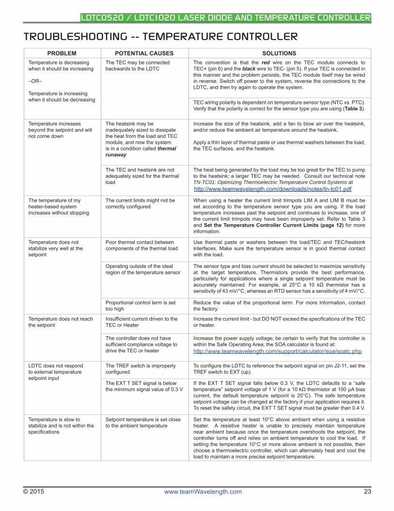
TROUBLESHOOTING -- TEMPERATURE CONTROLLER
PROBLEM POTENTIAL CAUSES SOLUTIONSTemperature is decreasing when it should be increasing
–OR–
Temperature is increasing when it should be decreasing
The TEC may be connected backwards to the LDTC
The convention is that the red wire on the TEC module connects to TEC+ (pin 6) and the black wire to TEC- (pin 5). If your TEC is connected in this manner and the problem persists, the TEC module itself may be wired in reverse. Switch off power to the system, reverse the connections to the LDTC, and then try again to operate the system.
TEC wiring polarity is dependent on temperature sensor type (NTC vs. PTC). Verify that the polarity is correct for the sensor type you are using (Table 3).
Temperature increases beyond the setpoint and will not come down
The heatsink may be inadequately sized to dissipate the heat from the load and TEC module, and now the system is in a condition called thermal runaway
Increase the size of the heatsink, add a fan to blow air over the heatsink, and/or reduce the ambient air temperature around the heatsink.
Apply a thin layer of thermal paste or use thermal washers between the load, the TEC surfaces, and the heatsink.
The TEC and heatsink are not adequately sized for the thermal load
The heat being generated by the load may be too great for the TEC to pump to the heatsink; a larger TEC may be needed. Consult our technical note TN-TC01: Optimizing Thermoelectric Temperature Control Systems at http://www.teamwavelength.com/downloads/notes/tn-tc01.pdfhttp://www.teamwavelength.com/downloads/notes/tn-tc01.pdf
The temperature of my heater-based system increases without stopping
The current limits might not be correctly confi gured
When using a heater the current limit trimpots LIM A and LIM B must be set according to the temperature sensor type you are using. If the load temperature increases past the setpoint and continues to increase, one of the current limit trimpots may have been improperly set. Refer to Table 3 and Set the Temperature Controller Current Limits (page 12) for more information.
Temperature does not stabilize very well at the setpoint
Poor thermal contact between components of the thermal load
Use thermal paste or washers between the load/TEC and TEC/heatsink interfaces. Make sure the temperature sensor is in good thermal contact with the load.
Operating outside of the ideal region of the temperature sensor
The sensor type and bias current should be selected to maximize sensitivity at the target temperature. Thermistors provide the best performance, particularly for applications where a single setpoint temperature must be accurately maintained. For example, at 25°C a 10 kΩ thermistor has a sensitivity of 43 mV/°C, whereas an RTD sensor has a sensitivity of 4 mV/°C.
Proportional control term is set too high
Reduce the value of the proportional term. For more information, contact the factory.
Temperature does not reach the setpoint
Insuffi cient current driven to the TEC or Heater
Increase the current limit - but DO NOT exceed the specifi cations of the TEC or heater.
The controller does not have suffi cient compliance voltage to drive the TEC or heater
Increase the power supply voltage; be certain to verify that the controller is within the Safe Operating Area; the SOA calculator is found at: http://www.teamwavelength.com/support/calculator/soa/soatc.php
LDTC does not respond to external temperature setpoint input
The TREF switch is improperly confi gured
To confi gure the LDTC to reference the setpoint signal on pin J2-11, set the TREF switch to EXT (up).
The EXT T SET signal is below the minimum signal value of 0.3 V
If the EXT T SET signal falls below 0.3 V, the LDTC defaults to a “safe temperature” setpoint voltage of 1 V (for a 10 kΩ thermistor at 100 μA bias current, the default temperature setpoint is 25°C). The safe temperature setpoint voltage can be changed at the factory if your application requires it. To reset the safety circuit, the EXT T SET signal must be greater than 0.4 V.
Temperature is slow to stabilize and is not within the specifi cations
Setpoint temperature is set close to the ambient temperature
Set the temperature at least 10°C above ambient when using a resistive heater. A resistive heater is unable to precisely maintain temperature near ambient because once the temperature overshoots the setpoint, the controller turns off and relies on ambient temperature to cool the load. If setting the temperature 10°C or more above ambient is not possible, then choose a thermoelectric controller, which can alternately heat and cool the load to maintain a more precise setpoint temperature.
© 2015 www.teamWavelength.com 24
LDTC0520 / LDTC1020 LASER DIODE AND TEMPERATURE CONTROLLER
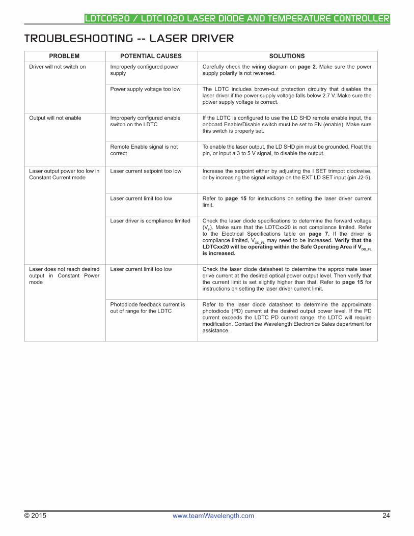
TROUBLESHOOTING -- LASER DRIVER
PROBLEM POTENTIAL CAUSES SOLUTIONSDriver will not switch on Improperly confi gured power
supplyCarefully check the wiring diagram on page 2. Make sure the power supply polarity is not reversed.
Power supply voltage too low The LDTC includes brown-out protection circuitry that disables the laser driver if the power supply voltage falls below 2.7 V. Make sure the power supply voltage is correct.
Output will not enable Improperly confi gured enable switch on the LDTC
If the LDTC is confi gured to use the LD SHD remote enable input, the onboard Enable/Disable switch must be set to EN (enable). Make sure this switch is properly set.
Remote Enable signal is not correct
To enable the laser output, the LD SHD pin must be grounded. Float the pin, or input a 3 to 5 V signal, to disable the output.
Laser output power too low in Constant Current mode
Laser current setpoint too low Increase the setpoint either by adjusting the I SET trimpot clockwise, or by increasing the signal voltage on the EXT LD SET input (pin J2-5).
Laser current limit too low Refer to page 15 for instructions on setting the laser driver current limit.
Laser driver is compliance limited Check the laser diode specifi cations to determine the forward voltage (VF). Make sure that the LDTCxx20 is not compliance limited. Refer to the Electrical Specifi cations table on page 7. If the driver is compliance limited, VDD_FL may need to be increased. Verify that the LDTCxx20 will be operating within the Safe Operating Area if VDD_FL is increased.
Laser does not reach desired output in Constant Power mode
Laser current limit too low Check the laser diode datasheet to determine the approximate laser drive current at the desired optical power output level. Then verify that the current limit is set slightly higher than that. Refer to page 15 for instructions on setting the laser driver current limit.
Photodiode feedback current is out of range for the LDTC
Refer to the laser diode datasheet to determine the approximate photodiode (PD) current at the desired output power level. If the PD current exceeds the LDTC PD current range, the LDTC will require modifi cation. Contact the Wavelength Electronics Sales department for assistance.
© 2015 www.teamWavelength.com 25
LDTC0520 / LDTC1020 LASER DIODE AND TEMPERATURE CONTROLLER
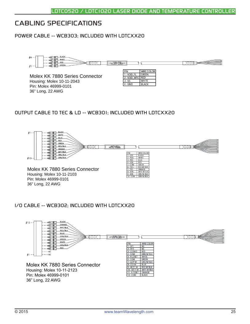
CABLING SPECIFICATIONS
POWER CABLE -- WCB303; INCLUDED WITH LDTCXX20
Molex KK 7880 Series ConnectorHousing: Molex 10-11-2043Pin: Molex 46999-010136” Long, 22 AWG
OUTPUT CABLE TO TEC & LD -- WCB301; INCLUDED WITH LDTCXX20
Molex KK 7880 Series ConnectorHousing: Molex 10-11-2103Pin: Molex 46999-010136” Long, 22 AWG
I/O CABLE -- WCB302; INCLUDED WITH LDTCXX20
Molex KK 7880 Series ConnectorHousing: Molex 10-11-2123Pin: Molex 46999-010136” Long, 22 AWG
© 2015 www.teamWavelength.com 26
LDTC0520 / LDTC1020 LASER DIODE AND TEMPERATURE CONTROLLER
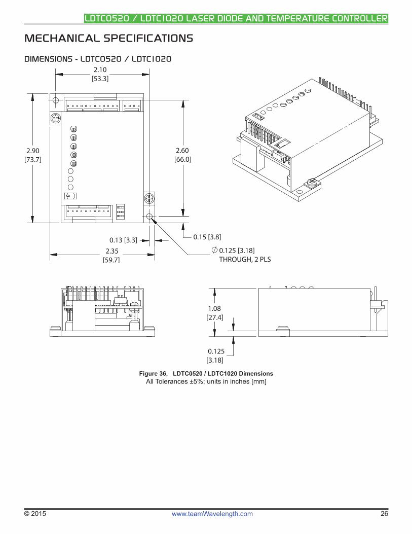
MECHANICAL SPECIFICATIONS
DIMENSIONS - LDTC0520 / LDTC1020
0.125[3.18]
1.08[27.4]
2.90 [73.7]
0.15 [3.8]
2.60[66.0]
2.10[53.3]
2.35[59.7]
0.125 [3.18]THROUGH, 2 PLS
0.13 [3.3]
Figure 36. LDTC0520 / LDTC1020 DimensionsAll Tolerances ±5%; units in inches [mm]
© 2015 www.teamWavelength.com 27
LDTC0520 / LDTC1020 LASER DIODE AND TEMPERATURE CONTROLLER
CERTIFICATION AND WARRANTY
CERTIFICATION
Wavelength Electronics, Inc. (Wavelength) certifi es that this product met its published specifi cations at the time of shipment. Wavelength further certifi es that its calibration measurements are traceable to the United States National Institute of Standards and Technology, to the extent allowed by that organization’s calibration facilities, and to the calibration facilities of other International Standards Organization members.
WARRANTY
This Wavelength product is warranted against defects in materials and workmanship for a period of one (1) year from date of shipment. During the warranty period, Wavelength will, at its option, either repair or replace products which prove to be defective.
WARRANTY SERVICE
For warranty service or repair, this product must be returned to the factory. An RMA is required for products returned to Wavelength for warranty service. The Buyer shall prepay shipping charges to Wavelength and Wavelength shall pay shipping charges to return the product to the Buyer upon determination of defective materials or workmanship. However, the Buyer shall pay all shipping charges, duties, and taxes for products returned to Wavelength from another country.
LIMITATIONS OF WARRANTY
The warranty shall not apply to defects resulting from improper use or misuse of the product or operation outside published specifi cations. No other warranty is expressed or implied. Wavelength specifi cally disclaims the implied warranties of merchantability and fi tness for a particular purpose.
EXCLUSIVE REMEDIES
The remedies provided herein are the Buyer’s sole and exclusive remedies. Wavelength shall not be liable for any direct, indirect, special, incidental, or consequential damages, whether based on contract, tort, or any other legal theory.
REVERSE ENGINEERING PROHIBITED
Buyer, End-User, or Third-Party Reseller are expressly prohibited from reverse engineering, decompiling, or disassembling this product.
NOTICE
The information contained in this document is subject to change without notice. Wavelength will not be liable for errors contained herein or for incidental or consequential damages in connection with the furnishing, performance, or use of this material. No part of this document may be translated to another language without the prior written consent of Wavelength.
SAFETY
There are no user-serviceable parts inside this product. Return the product to Wavelength Electronics for service and repair to ensure that safety features are maintained.
LIFE SUPPORT POLICY
This important safety information applies to all Wavelength electrical and electronic products and accessories:
As a general policy, Wavelength Electronics, Inc. does not recommend the use of any of its products in life support applications where the failure or malfunction of the Wavelength product can be reasonably expected to cause failure of the life support device or to signifi cantly affect its safety or effectiveness. Wavelength will not knowingly sell its products for use in such applications unless it receives written assurances satisfactory to Wavelength that the risks of injury or damage have been minimized, the customer assumes all such risks, and there is no product liability for Wavelength. Examples of devices considered to be life support devices are neonatal oxygen analyzers, nerve stimulators (for any use), auto-transfusion devices, blood pumps, defi brillators, arrhythmia detectors and alarms, pacemakers, hemodialysis systems, peritoneal dialysis systems, ventilators of all types, and infusion pumps as well as other devices designated as “critical” by the FDA. The above are representative examples only and are not intended to be conclusive or exclusive of any other life support device.
REVISION HISTORY
DOCUMENT NUMBER: LDTC1020-00400
REV. DATE CHANGEI December
2013Updated test load instructions, extended warranty, added resistive heater stability information
J August 2014 Updated external setpoint control instructions, and PI equations
K December 2014
Added Molex part numbers on cabling specs
L April 2015 Added ESD protection on LD shutdown pin. Updated for product Rev C.
51 Evergreen DriveBozeman, Montana 59771
406-587-4910 (tel)406-587-4911 (fax)
Sales & Tech [email protected]