datasheet…as ® adc-v90 ata sheet ev 23 201509v9023 3 user notice: 2 table of contents ... as ®...
TRANSCRIPT

V90
Shaping the future of sound reinforcement
Datasheet
Applies to Part Numbers:
576125, 577125 and 577135
Intellivox ADC-V90
EN 54 -24

AXYS® ADC-V90 data sheet rev 2.3
201509/V90_2.32
• No part of this document including the software described in it may be reproduced, transmitted, transcribed, stored in a database system or translated without the express written permission of Duran Audio BV. Documentation kept by the end-user for backup purposes is excluded from the above mentioned.
• All products and corporate names mentioned in this document may be registered trademarks or copyrights of their respective companies. They are used here for indicative purposes only.
• The information contained in this document has been carefully checked for accuracy, however no guarantee is given with respect to the correctness. Duran Audio BV accepts no responsibility or liability for any errors or inaccuracies that may appear in this document or the products and/or software described in it.
• Specifications and information contained in this document are subject to change at any time without notice.
User Notice:

AXYS® ADC-V90 data sheet rev 2.3
201509/V90_2.3 3
User Notice: . . . . . . . . . . . . . . . . . . . . . . . . . . . . . . . . . . . . . . . . . . . . . . . . . . . . . . . . . . . . . . . . . 2
Table of Contents . . . . . . . . . . . . . . . . . . . . . . . . . . . . . . . . . . . . . . . . . . . . . . . . . . . . . . . . . . . . . 3
1. Architectural and Engineering Specifications . . . . . . . . . . . . . . . . . . . . . . . . . . . . . . . . . . . . . . 4
2. Specifications . . . . . . . . . . . . . . . . . . . . . . . . . . . . . . . . . . . . . . . . . . . . . . . . . . . . . . . . . . . . . . 5
3. SPL Plots . . . . . . . . . . . . . . . . . . . . . . . . . . . . . . . . . . . . . . . . . . . . . . . . . . . . . . . . . . . . . . . . . . 7
4. Impedance Plots . . . . . . . . . . . . . . . . . . . . . . . . . . . . . . . . . . . . . . . . . . . . . . . . . . . . . . . . . . . . 8
5. Mechanical Details . . . . . . . . . . . . . . . . . . . . . . . . . . . . . . . . . . . . . . . . . . . . . . . . . . . . . . . . . . 9
6. Physical References. . . . . . . . . . . . . . . . . . . . . . . . . . . . . . . . . . . . . . . . . . . . . . . . . . . . . . . . . 10
7. Optional Accessories . . . . . . . . . . . . . . . . . . . . . . . . . . . . . . . . . . . . . . . . . . . . . . . . . . . . . . . . 11
Table of Contents

AXYS® ADC-V90 data sheet rev 2.3
201509/V90_2.34
The unit shall be constructed as a line-array of six 4” full-range loudspeakers, equipped with moisture resistant diaphragms and shall be designed for use in 100 V/70 V professional audio installations. The unit is intended for use in both public address and voice alarm systems and shall be compliant with EN 54-24. The unit shall be suitable for both indoor and outdoor use and therefore shall be compliant with the environmental requirements of EN 54-24 for both types A & B.
All necessary array signal processing shall be implemented in the analogue domain by means of a fixed set of internal filters that shall realize appropriate output channel filter transfer functions. Besides the aforementioned, the unit shall have the following functions:
• Switchable High Pass Filter (HPF).
• Switchable EQ contour.
• Switchable power taps: 100 W, 50 W and 25 W.
The audio signal shall be connected to a ceramic terminal block. A thermal fuse shall be included in the internal audio path to disconnect the unit from the 100 V/ 70V line should the unit be exposed to extreme heat and/or fire. An additional internal fuse shall be used to protect the unit from excess current. All connectors, fuses and switches shall be grouped together inside the unit and shall be accessible from a cover plate on the front of the unit. A gland shall be provided for cable entry on the rear of the unit.
A LED shall be fitted to the loudspeaker baffle which illuminates on detection of a constant high frequency pilot-tone, which shall indicate that the unit is properly connected to the 100 V/70 V line. The LED shall be visible with the grill installed.
The enclosure shall be constructed of steel finished with an epoxy coating. At the back side of the enclosure a total of two bracket attachment points shall be provided (located near the outer ends). The protective front shall consist of a perforated steel grill which can be clicked onto four snap-in studs mounted on the enclosure. For added security grill security screws shall be provided to lock the steel grill in place.
The complete loudspeaker unit shall meet the following criteria (100 W tap / HPF flat / EQ flat):
Typical frequency range of the complete array: 220 - 10k Hz on reference axis (+/- 3 dB), max. SPL at 4 m of 100 dBSPL continuous, fixed nominal vertical opening angle at 4 m of 27° (-6 dB, averaged 1k to 4k Hz), fixed vertical aiming angle of -4°, fixed horizontal opening angle at 4 m of 135° (-6 dB, averaged 1k to 4k Hz).
Dimensions are 865 mm (34.1”) H x 134 mm (5.3”) W x 92 mm (3.6”) D. Weight 10 kg (22 lbs).
The loudspeaker unit shall be the AXYS® model Intellivox ADC - V90.
1. Architectural and Engineering Specifications

AXYS® ADC-V90 data sheet rev 2.3
201509/V90_2.3 5
Acoustical:
Frequency range2, 3 : 220 - 10k Hz (+/-3 dB, HPF flat / EQ flat) : 120 - 12k Hz (-10 dB, HPF flat / EQ flat)
Sensitivity (1 W / 4 m)2, 4 : 80 dBSPL (100 W tap / HPF flat / EQ flat) : 77 dBSPL (100 W tap / HPF active / EQ active
Maximum SPL (100 W / 4 m)2, 5 : 100 dBSPL (100 W tap / HPF flat / EQ flat) : 97 dBSPL (100 W tap / HPF active / EQ active
Horizontal coverage (-6 dB)6, 8, 9 - 500 Hz : 211° - 1k Hz : 196° - 2k Hz : 128° - 4k Hz : 86° - 8k Hz : 40°
Vertical coverage (-6 dB)7, 8, 9 - 500 Hz : 52° - 1k Hz : 34° - 2k Hz : 27° - 4k Hz : 19° - 8k Hz : 12°
Steering angle : Vertical -4° Typical throw : 15 m
Electrical:
Rated Impedance10, 11 - 100 W tap : 100 Ω - 50 W tap : 200 Ω - 25 W tap : 400 Ω
Rated Noise Power10 : 100 Wrms (100 W tap)
Rated Noise Voltage10 : 100 Vrms
Control switches12 - Tap setting : 100 W / 50 W / 25 W - Highpass filter13 : HPF active / Flat - Correction EQ : EQ active / Flat
Fuses - Glass fuse12 : 1 A (slow type, 20 mm, replaceable) - Thermal fuse12 : Open temperature 104 °C
Rating >= 8 A @ 250 VAC One-shot operation (replaceable)
Connections - Terminal block12 : 100 V / 0 V / Earth (connected to enclosure housing) - Material : Steatite housing with brass inserts - Rated cross-section : 2.5 mm2
Cable gland - Maximum diameter : 13.5 mm
2. Specifications1
AXYS® ADC-V90 data sheet rev 2.3
201509/V90_2.36
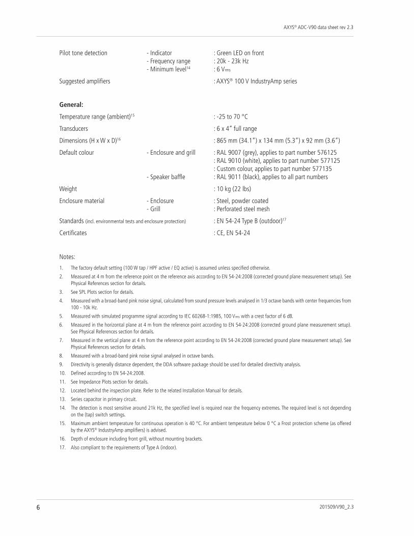
Pilot tone detection - Indicator : Green LED on front - Frequency range : 20k - 23k Hz - Minimum level14 : 6 Vrms
Suggested amplifiers : AXYS® 100 V IndustryAmp series
General:
Temperature range (ambient)15 : -25 to 70 °C
Transducers : 6 x 4” full range
Dimensions (H x W x D)16 : 865 mm (34.1”) x 134 mm (5.3”) x 92 mm (3.6”)
Default colour - Enclosure and grill : RAL 9007 (grey), applies to part number 576125 : RAL 9010 (white), applies to part number 577125 : Custom colour, applies to part number 577135 - Speaker baffle : RAL 9011 (black), applies to all part numbers
Weight : 10 kg (22 lbs)
Enclosure material - Enclosure : Steel, powder coated - Grill : Perforated steel mesh
Standards (incl. environmental tests and enclosure protection) : EN 54-24 Type B (outdoor)17
Certificates : CE, EN 54-24
Notes:
1. The factory default setting (100 W tap / HPF active / EQ active) is assumed unless specified otherwise.
2. Measured at 4 m from the reference point on the reference axis according to EN 54-24:2008 (corrected ground plane measurement setup). See Physical References section for details.
3. See SPL Plots section for details.
4. Measured with a broad-band pink noise signal, calculated from sound pressure levels analysed in 1/3 octave bands with center frequencies from 100 - 10k Hz.
5. Measured with simulated programme signal according to IEC 60268-1:1985, 100 Vrms with a crest factor of 6 dB.
6. Measured in the horizontal plane at 4 m from the reference point according to EN 54-24:2008 (corrected ground plane measurement setup). See Physical References section for details.
7. Measured in the vertical plane at 4 m from the reference point according to EN 54-24:2008 (corrected ground plane measurement setup). See Physical References section for details.
8. Measured with a broad-band pink noise signal analysed in octave bands.
9. Directivity is generally distance dependent, the DDA software package should be used for detailed directivity analysis.
10. Defined according to EN 54-24:2008.
11. See Impedance Plots section for details.
12. Located behind the inspection plate. Refer to the related Installation Manual for details.
13. Series capacitor in primary circuit.
14. The detection is most sensitive around 21k Hz, the specified level is required near the frequency extremes. The required level is not depending on the (tap) switch settings.
15. Maximum ambient temperature for continuous operation is 40 °C. For ambient temperature below 0 °C a Frost protection scheme (as offered by the AXYS® IndustryAmp amplifiers) is advised.
16. Depth of enclosure including front grill, without mounting brackets.
17. Also compliant to the requirements of Type A (indoor).

AXYS® ADC-V90 data sheet rev 2.3
201509/V90_2.3 7
3. SPL Plots
-40
+10
-35
-30
-25
-20
-15
-10
-5
+0
+5
dBSPL
40 20k50 100 200 500 1k 2k 5k 10kHz
-40
+10
-35
-30
-25
-20
-15
-10
-5
+0
+5
dBSPL
40 20k50 100 200 500 1k 2k 5k 10kHz
-20
+20
-15
-10
-5
+0
+5
+10
+15
dB
20 20k50 100 200 500 1k 2k 5k 10kHz
-40
+10
-35
-30
-25
-20
-15
-10
-5
+0
+5
dBSPL
40 20k50 100 200 500 1k 2k 5k 10kHz
-40
+10
-35
-30
-25
-20
-15
-10
-5
+0
+5
dBSPL
40 20k50 100 200 500 1k 2k 5k 10kHz
-20
+20
-15
-10
-5
+0
+5
+10
+15
dB
20 20k50 100 200 500 1k 2k 5k 10kHz
Fig 1 Normalized SPL vs frequency, 100 W tap / HPF flat / EQ flat.
Fig 3 Normalized SPL vs frequency, 100 W tap / HPF active / EQ flat.
Fig 5 EQ correction.
Fig 2 Normalized SPL vs frequency, 100 W tap / HPF flat / EQ active.
Fig 4 Normalized SPL vs frequency, 100 W tap / HPF active / EQ active.
Fig 6 HPF correction (100 W tap).
Note: SPL data obtained from corrected ground plane measurements, MLS method, 8 ms time window, 1/3 oct averaged. SPL plots scaled to 0 dBSPL at 1k Hz.

AXYS® ADC-V90 data sheet rev 2.3
201509/V90_2.38
4. Impedance Plots
-180
+180
-160
-140
-120
-100
-80
-60
-40
-20
+0
+20
+40
+60
+80
+100
+120
+140
+160
deg
0
500
50
100
150
200
250
300
350
400
450
Ohm
10 40k20 50 100 200 500 1k 2k 5k 10k 20kHz
-180
+180
-160
-140
-120
-100
-80
-60
-40
-20
+0
+20
+40
+60
+80
+100
+120
+140
+160
deg
100
1k
200
300
400
500
600
700
800
.9k
Ohm
10 40k20 50 100 200 500 1k 2k 5k 10k 20kHz
-180
+180
-160
-140
-120
-100
-80
-60
-40
-20
+0
+20
+40
+60
+80
+100
+120
+140
+160
deg
200
2k
400
600
800
1k
1.2k
1.4k
1.6k
1.8k
Ohm
10 40k20 50 100 200 500 1k 2k 5k 10k 20kHz
-180
+180
-160
-140
-120
-100
-80
-60
-40
-20
+0
+20
+40
+60
+80
+100
+120
+140
+160
deg
50
500
100
150
200
250
300
350
400
450
Ohm
10 40k20 50 100 200 500 1k 2k 5k 10k 20kHz
-180
+180
-160
-140
-120
-100
-80
-60
-40
-20
+0
+20
+40
+60
+80
+100
+120
+140
+160
deg
100
1k
200
300
400
500
600
700
800
.9k
Ohm
10 40k20 50 100 200 500 1k 2k 5k 10k 20kHz
-180
+180
-160
-140
-120
-100
-80
-60
-40
-20
+0
+20
+40
+60
+80
+100
+120
+140
+160
deg
200
2k
400
600
800
1k
1.2k
1.4k
1.6k
1.8k
Ohm
10 40k20 50 100 200 500 1k 2k 5k 10k 20kHz
Fig 7 Impedance magnitude (red) and phase (green) vs frequency, 100 W tap / HPF flat / EQ flat.
Fig 9 Impedance magnitude (red) and phase (green) vs frequency, 50 W tap / HPF flat / EQ flat.
Fig 11 Impedance magnitude (red) and phase (green) vs frequency, 25 W tap / HPF flat / EQ flat.
Fig 8 Impedance magnitude (red) and phase (green) vs frequency, 100 W tap / HPF flat / EQ active.
Fig 10 Impedance magnitude (red) and phase (green) vs frequency, 50 W tap / HPF flat / EQ active.
Fig 12 Impedance magnitude (red) and phase (green) vs frequency, 25 W tap / HPF flat / EQ active.

AXYS® ADC-V90 data sheet rev 2.3
201509/V90_2.3 9
5. Mechanical Details
134
865
393
60,3
768
36,7
92,5
118,6
472
52 82
787
Reference point foracoustical mounting
height

AXYS® ADC-V90 data sheet rev 2.3
201509/V90_2.310
6. Physical References
7
6
2
5 4
1
Key 1 loudspeaker enclosure2 loudspeaker front3 reference axis4 reference plane5 reference point6 horizontal plane7 vertical plane
3
Notes:
1. The reference plane (4) intersects the enclosure through the loudspeaker front baffle (2).
2. The reference point (5), located in the reference plane (4), coincides with the center of the upper loudspeaker.
3. The reference axis (3) is aimed 4° downwards.
4. The reference axis (3) intersects the horizontal plane (6) at 4 m distance.
5. The vertical plane (7) contains the reference axis (3).

AXYS® ADC-V90 data sheet rev 2.3
201509/V90_2.3 11
7. Optional Accessories
Wall Bracket Set (25 mm)(Supplied as standard)
Order code: 802227
(2 pcs incl. fasteners)
Standard colour RAL 9007 (grey)
Hinge Bracket 90°Order code: 802005
(1 pcs per pack)
Standard colour RAL 9007 (grey)
Swivel Bracket 90°Order code: 806668
(1 pcs per pack)
Standard colour RAL 9007 (grey)
Swivel Bracket 45°Order code: 806678
(1 pcs per pack)
Standard colour RAL 9007 (grey)
Wall Bracket Set (25 mm)Order code: 802225
(2 pcs incl. fasteners)
Colour RAL 9010 (white)
Wall Bracket Set (35 mm)Order code: 802235
(2 pcs incl. fasteners)
Colour RAL 9010 (white)
Wall Bracket Set (60 mm)Order code: 802260
(2 pcs incl. fasteners)
Colour RAL 9010 (white)
Hinge Bracket 90°Order code: 802000
(1 pcs per pack)
Colour RAL 9010 (white)
Swivel Bracket 90°Order code: 806608
(1 pcs per pack)
Colour RAL 9010 (white)
Swivel Bracket 45°Order code: 806618
(1 pcs per pack)
Colour RAL 9010 (white)
Small Hinge SetOrder code: 806602
(2 pcs pack)

DURAN AUDIO BVKoxkampseweg 10, 5301 KK Zaltbommel, The Netherlands.
tel. +31 418 515583 fax. +31 418 518077http://www.duran-audio.com [email protected]