datasheet search site | : 48-pin 12mm x 20mm tsop-i 48-ball 6mm x 8mm tfbga general description the...
TRANSCRIPT
LY62L51316 Rev. 1.6 512K X 16 BIT LOW POWER CMOS SRAM
Lyontek Inc. reserves the rights to change the specifications and products without notice. 5F, No. 2, Industry E. Rd. IX, Science-Based Industrial Park, Hsinchu 300, Taiwan. TEL: 886-3-6668838 FAX: 886-3-6668836
0
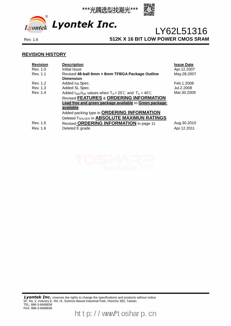
REVISION HISTORY
Revision Description Issue Date
Rev. 1.0 Initial Issue Apr.12.2007
Rev. 1.1 Revised 48-ball 6mm × 8mm TFBGA Package Outline
Dimension
May.28.2007
Rev. 1.2 Added ISB Spec. Feb.1.2008
Rev. 1.3 Added SL Spec. Jul.2.2008
Rev. 1.4 Added ISB1/IDR values when TA = 25℃ and TA = 40℃
Revised FEATURES & ORDERING INFORMATION
Lead free and green package available to Green package
available
Added packing type in ORDERING INFORMATION
Deleted TSOLDER in ABSOLUTE MAXIMUN RATINGS
Mar.30.2009
Rev. 1.5 Revised ORDERING INFORMATION in page 11 Aug.30.2010
Rev. 1.6 Deleted E grade Apr.12.2011
http://www.tosharp.cn

LY62L51316 Rev. 1.6 512K X 16 BIT LOW POWER CMOS SRAM
Lyontek Inc. reserves the rights to change the specifications and products without notice. 5F, No. 2, Industry E. Rd. IX, Science-Based Industrial Park, Hsinchu 300, Taiwan. TEL: 886-3-6668838 FAX: 886-3-6668836
1
FEATURES Fast access time : 55/70ns Low power consumption:
Operating current : 30/20mA (TYP.)
Standby current : 5A (TYP.) LL-version
1.5A (TYP.) SL-version Single 2.7V ~ 3.6V power supply All inputs and outputs TTL compatible Fully static operation Tri-state output Data byte control : LB# (DQ0 ~ DQ7) UB# (DQ8 ~ DQ15) Data retention voltage : 1.2V (MIN.) Green package available Package : 48-pin 12mm x 20mm TSOP-I 48-ball 6mm x 8mm TFBGA
GENERAL DESCRIPTION The LY62L51316 is a 8,388,608-bit low power CMOS static random access memory organized as 524,288 words by 16 bits. It is fabricated using very high performance, high reliability CMOS technology. Its standby current is stable within the range of operating temperature.
The LY62L51316 is well designed for low power application, and particularly well suited for battery back-up nonvolatile memory application. The LY62L51316 operates from a single power supply of 2.7V ~ 3.6V and all inputs and outputs are fully TTL compatible
PRODUCT FAMILY
Product Family
Operating Temperature
Vcc Range Speed Power Dissipation
Standby(ISB1,TYP.) Operating(Icc,TYP.)
LY62L51316 0 ~ 70℃ 2.7 ~ 3.6V 55/70ns 5µA(LL)/1.5µA(SL) 30/20mA
LY62L51316(I) -40 ~ 85℃ 2.7 ~ 3.6V 55/70ns 5µA(LL)/1.5µA(SL) 30/20mA
FUNCTIONAL BLOCK DIAGRAM
CONTROL
CIRCUIT
DECODER512Kx16
MEMORY ARRAY
COLUMN I/O
A0-A18
Vcc
Vss
DQ8-DQ15
Upper Byte
DQ0-DQ7
Lower ByteI/O DATA
CIRCUIT
CE2
WE#
OE#
LB#
UB#
CE#
PIN DESCRIPTION
SYMBOL DESCRIPTION
A0 - A18 Address Inputs
DQ0 – DQ15 Data Inputs/Outputs
CE#, CE2 Chip Enable Input
WE# Write Enable Input
OE# Output Enable Input
LB# Lower Byte Control
UB# Upper Byte Control
VCC Power Supply
VSS Ground
http://www.tosharp.cn
LY62L51316 Rev. 1.6 512K X 16 BIT LOW POWER CMOS SRAM
Lyontek Inc. reserves the rights to change the specifications and products without notice. 5F, No. 2, Industry E. Rd. IX, Science-Based Industrial Park, Hsinchu 300, Taiwan. TEL: 886-3-6668838 FAX: 886-3-6668836
2
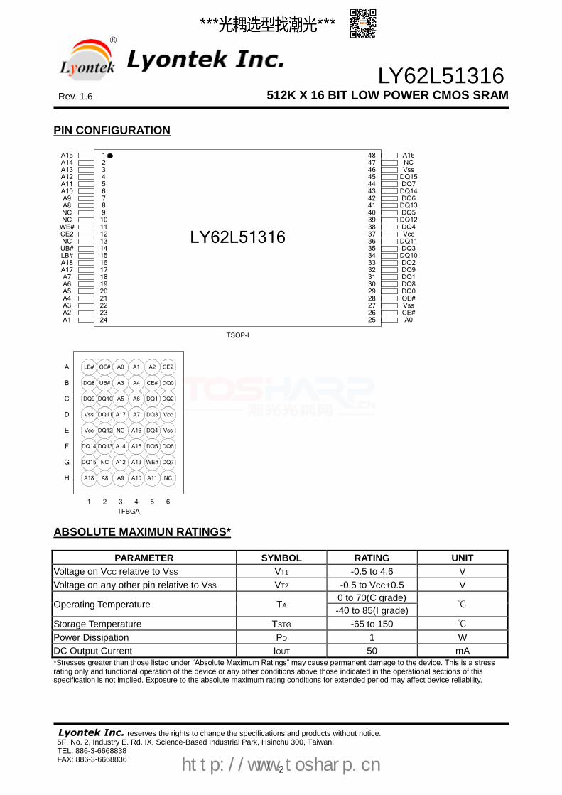
PIN CONFIGURATION
TSOP-I
A15A14A13A12
A8
LY62L51316
87654321
A11A10A9
NCNC
WE#CE2NCUB#LB#A18A17A7A6A5A4A3A2A1
14131211109
1615
222120191817
2423
DQ13
NC
DQ15DQ7
DQ14DQ6
44
414243
A16
Vss
4847
4546
33
363534
383940
37
25
282726
303132
29
DQ12DQ5
DQ4Vcc
DQ11DQ3
DQ10DQ2
DQ1DQ9
DQ8DQ0OE#VssCE#A0
TFBGA
NC
A3
A10A9 A11
A0
A14
A8 NC
WE#
DQ9
DQ14
DQ15
A18
Vss
CE2
A13
DQ8
Vcc
Vcc
DQ7
A15
Vss
CE#
LB#
DQ6
DQ2
DQ0
A2OE# A1
A6A5
A4UB#
1 2 3 4 5 6
H
G
C
D
E
F
A
B
A12
NC
A17 A7
A16
DQ10
DQ11
DQ12
DQ13 DQ5
DQ4
DQ3
DQ1
ABSOLUTE MAXIMUN RATINGS*
PARAMETER SYMBOL RATING UNIT
Voltage on VCC relative to VSS VT1 -0.5 to 4.6 V
Voltage on any other pin relative to VSS VT2 -0.5 to VCC+0.5 V
Operating Temperature TA 0 to 70(C grade)
℃ -40 to 85(I grade)
Storage Temperature TSTG -65 to 150 ℃
Power Dissipation PD 1 W
DC Output Current IOUT 50 mA
*Stresses greater than those listed under “Absolute Maximum Ratings” may cause permanent damage to the device. This is a stress rating only and functional operation of the device or any other conditions above those indicated in the operational sections of this specification is not implied. Exposure to the absolute maximum rating conditions for extended period may affect device reliability.
http://www.tosharp.cn

LY62L51316 Rev. 1.6 512K X 16 BIT LOW POWER CMOS SRAM
Lyontek Inc. reserves the rights to change the specifications and products without notice. 5F, No. 2, Industry E. Rd. IX, Science-Based Industrial Park, Hsinchu 300, Taiwan. TEL: 886-3-6668838 FAX: 886-3-6668836
3
TRUTH TABLE
MODE CE# CE2 OE# WE# LB# UB# I/O OPERATION
SUPPLY CURRENT DQ0-DQ7 DQ8-DQ15
Standby H X X
X L X
X X X
X X X
X X H
X X H
High – Z High – Z High – Z
High – Z High – Z High – Z
ISB,ISB1
Output Disable L L
H H
H H
H H
L X
X L
High – Z High – Z
High – Z High – Z
ICC,ICC1
Read L L L
H H H
L L L
H H H
L H L
H L L
DOUT High – Z
DOUT
High – Z DOUT
DOUT ICC,ICC1
Write L L L
H H H
X X X
L L L
L H L
H L L
DIN High – Z
DIN
High – Z DIN
DIN ICC,ICC1
Note: H = VIH, L = VIL, X = Don't care.
DC ELECTRICAL CHARACTERISTICS
PARAMETER SYMBOL TEST CONDITION MIN. TYP. *4
MAX. UNIT
Supply Voltage VCC 2.7 3.0 3.6 V
Input High Voltage VIH*1
2.2 - VCC+0.3 V
Input Low Voltage VIL*2
- 0.2 - 0.6 V
Input Leakage Current ILI VCC ≧ VIN ≧ VSS - 1 - 1 µA
Output Leakage
Current ILO
VCC ≧ VOUT ≧ VSS,
Output Disabled
- 1 - 1 µA
Output High Voltage VOH IOH = -1mA 2.2 2.7 - V
Output Low Voltage VOL IOL = 2mA - - 0.4 V
Average Operating
Power supply Current
ICC
Cycle time = Min.
CE# = VIL and CE2 = VIH
II/O = 0mA
Other pins at VIL or VIH
- 55 - 30 40 mA
- 70 - 20 30 mA
ICC1
Cycle time = 1µs
CE#≦0.2V and CE2≧VCC-0.2V
II/O = 0mA
Other pins at 0.2V or VCC-0.2V
- 4 8 mA
Standby Power
Supply Current
ISB CE# = VIH or CE2 = VIL
Other pins at VIL or VIH - 0.15 1 mA
ISB1
CE# ≧VCC-0.2V
or CE2≦0.2V
Other pins at 0.2V
or VCC-0.2V
LL - 5 30 µA
LLI - 5 50 µA
SL*5
SLI*5
25℃ - 1.5 5 µA
40℃ - 1.5 5 µA
SL - 1.5 15 µA
SLI - 1.5 20 µA Notes: 1. VIH(max) = VCC + 3.0V for pulse width less than 10ns. 2. VIL(min) = VSS - 3.0V for pulse width less than 10ns. 3. Over/Undershoot specifications are characterized, not 100% tested. 4. Typical values are included for reference only and are not guaranteed or tested.
Typical values are measured at VCC = VCC(TYP.) and TA = 25℃
5. This parameter is measured at VCC = 3.0V
http://www.tosharp.cn

LY62L51316 Rev. 1.6 512K X 16 BIT LOW POWER CMOS SRAM
Lyontek Inc. reserves the rights to change the specifications and products without notice. 5F, No. 2, Industry E. Rd. IX, Science-Based Industrial Park, Hsinchu 300, Taiwan. TEL: 886-3-6668838 FAX: 886-3-6668836
4
CAPACITANCE (TA = 25℃, f = 1.0MHz)
PARAMETER SYMBOL MIN. MAX UNIT
Input Capacitance CIN - 6 pF
Input/Output Capacitance CI/O - 8 pF
Note : These parameters are guaranteed by device characterization, but not production tested.
AC TEST CONDITIONS
Input Pulse Levels 0.2V to VCC - 0.2V
Input Rise and Fall Times 3ns
Input and Output Timing Reference Levels 1.5V
Output Load CL = 30pF + 1TTL, IOH/IOL = -1mA/2mA
AC ELECTRICAL CHARACTERISTICS (1) READ CYCLE
PARAMETER SYM. LY62L51316-55 LY62L51316-70 UNIT
MIN. MAX. MIN. MAX.
Read Cycle Time tRC 55 - 70 - ns
Address Access Time tAA - 55 - 70 ns
Chip Enable Access Time tACE - 55 - 70 ns
Output Enable Access Time tOE - 30 - 35 ns
Chip Enable to Output in Low-Z tCLZ* 10 - 10 - ns
Output Enable to Output in Low-Z tOLZ* 5 - 5 - ns
Chip Disable to Output in High-Z tCHZ* - 20 - 25 ns
Output Disable to Output in High-Z tOHZ* - 20 - 25 ns
Output Hold from Address Change tOH 10 - 10 - ns
LB#, UB# Access Time tBA - 55 - 70 ns
LB#, UB# to High-Z Output tBHZ* - 25 - 30 ns
LB#, UB# to Low-Z Output tBLZ* 10 - 10 - ns
(2) WRITE CYCLE
PARAMETER SYM. LY62L51316-55 LY62L51316-70 UNIT
MIN. MAX. MIN. MAX.
Write Cycle Time tWC 55 - 70 - ns
Address Valid to End of Write tAW 50 - 60 - ns
Chip Enable to End of Write tCW 50 - 60 - ns
Address Set-up Time tAS 0 - 0 - ns
Write Pulse Width tWP 45 - 55 - ns
Write Recovery Time tWR 0 - 0 - ns
Data to Write Time Overlap tDW 25 - 30 - ns
Data Hold from End of Write Time tDH 0 - 0 - ns
Output Active from End of Write tOW* 5 - 5 - ns
Write to Output in High-Z tWHZ* - 20 - 25 ns
LB#, UB# Valid to End of Write tBW 45 - 60 - ns *These parameters are guaranteed by device characterization, but not production tested.
http://www.tosharp.cn

LY62L51316 Rev. 1.6 512K X 16 BIT LOW POWER CMOS SRAM
Lyontek Inc. reserves the rights to change the specifications and products without notice. 5F, No. 2, Industry E. Rd. IX, Science-Based Industrial Park, Hsinchu 300, Taiwan. TEL: 886-3-6668838 FAX: 886-3-6668836
5
TIMING WAVEFORMS READ CYCLE 1 (Address Controlled) (1,2)
Dout Data Valid
tOHtAA
Address
tRC
Previous Data Valid
READ CYCLE 2 (CE# and CE2 and OE# Controlled) (1,3,4,5)
Dout Data ValidHigh-ZHigh-Z
tCLZ
tOLZ
tCHZ
tOHZ
tOH
OE#
tOE
LB#,UB#
tBHZ
tACE
tBA
tBLZ
CE#
tAA
Address
tRC
CE2
Notes : 1.WE#is high for read cycle. 2.Device is continuously selected OE# = low, CE# = low, CE2 = high, LB# or UB# = low.
3.Address must be valid prior to or coincident with CE# = low, CE2 = high, LB# or UB# = low transition; otherwise tAA is the limiting parameter. 4.tCLZ, tBLZ, tOLZ, tCHZ, tBHZ and tOHZ are specified with CL = 5pF. Transition is measured ±500mV from steady state.
5.At any given temperature and voltage condition, tCHZ is less than tCLZ , tBHZ is less than tBLZ, tOHZ is less than tOLZ.
http://www.tosharp.cn

LY62L51316 Rev. 1.6 512K X 16 BIT LOW POWER CMOS SRAM
Lyontek Inc. reserves the rights to change the specifications and products without notice. 5F, No. 2, Industry E. Rd. IX, Science-Based Industrial Park, Hsinchu 300, Taiwan. TEL: 886-3-6668838 FAX: 886-3-6668836
6
WRITE CYCLE 1 (WE# Controlled) (1,2,3,5,6)
Dout
Din Data Valid
tDW tDH
(4)High-Z
tWHZ
WE#
tWP
tCW
tWRtAS
(4)
TOW
LB#,UB#
tBW
CE#
tAW
Address
tWC
CE2
WRITE CYCLE 2 (CE# and CE2 Controlled) (1,2,5,6)
Dout
Din Data Valid
tDW tDH
(4)High-Z
tWHZ
WE#
LB#,UB#
tCW
tWP
tBW
CE#
Address
tWRtAS
tAW
tWC
CE2
http://www.tosharp.cn

LY62L51316 Rev. 1.6 512K X 16 BIT LOW POWER CMOS SRAM
Lyontek Inc. reserves the rights to change the specifications and products without notice. 5F, No. 2, Industry E. Rd. IX, Science-Based Industrial Park, Hsinchu 300, Taiwan. TEL: 886-3-6668838 FAX: 886-3-6668836
7
WRITE CYCLE 3 (LB#,UB# Controlled) (1,2,5,6)
Dout
Din Data Valid
tDW tDH
(4)High-Z
tWHZ
WE#
LB#,UB#
tCWtAS
tWP
tBW
CE#
Address
tWRtAW
tWC
CE2
Notes : 1.WE#,CE#, LB#, UB# must be high or CE2 must be low during all address transitions. 2.A write occurs during the overlap of a low CE#, high CE2, low WE#, LB# or UB# = low. 3.During a WE# controlled write cycle with OE# low, tWP must be greater than tWHZ + tDW to allow the drivers to turn off and data to be
placed on the bus.
4.During this period, I/O pins are in the output state, and input signals must not be applied. 5.If the CE#, LB#, UB# low transition and CE2 high transition occurs simultaneously with or after WE# low transition, the outputs remain
in a high impedance state. 6.tOW and tWHZ are specified with CL = 5pF. Transition is measured ±500mV from steady state.
http://www.tosharp.cn

LY62L51316 Rev. 1.6 512K X 16 BIT LOW POWER CMOS SRAM
Lyontek Inc. reserves the rights to change the specifications and products without notice. 5F, No. 2, Industry E. Rd. IX, Science-Based Industrial Park, Hsinchu 300, Taiwan. TEL: 886-3-6668838 FAX: 886-3-6668836
8
DATA RETENTION CHARACTERISTICS
PARAMETER SYMBOL TEST CONDITION MIN. TYP. MAX. UNIT
VCC for Data Retention VDR CE# ≧ VCC - 0.2V or CE2≦0.2V 1.2 - 3.6 V
Data Retention Current IDR
VCC = 1.2V
CE# ≧VCC-0.2V or CE2≦0.2V Other pins at 0.2V or VCC-0.2V
LL - 2 25 µA
LLI - 2 40 µA
SL
SLI
25℃ - 1 3 µA
40℃ - 1 3 µA
SL - 1 15 µA
SLI - 1 20 µA
Chip Disable to Data Retention Time
tCDR See Data Retention Waveforms (below)
0 - - ns
Recovery Time tR tRC* - - ns
tRC* = Read Cycle Time
DATA RETENTION WAVEFORM Low Vcc Data Retention Waveform (1) (CE# controlled)
Vcc
CE#
VDR ≧ 1.2V
CE# ≧ Vcc-0.2V
Vcc(min.)
VIH
tRtCDR
VIH
Vcc(min.)
Low Vcc Data Retention Waveform (2) (CE2 controlled)
Vcc
CE2
VDR ≧ 1.2V
CE2 ≦ 0.2V
Vcc(min.)
VIL
tRtCDR
VIL
Vcc(min.)
Low Vcc Data Retention Waveform (3) (LB#, UB# controlled)
Vcc
LB#,UB#
VDR ≧ 1.2V
LB#,UB# ≧ Vcc-0.2V
Vcc(min.)
VIH
tRtCDR
VIH
Vcc(min.)
http://www.tosharp.cn

LY62L51316 Rev. 1.6 512K X 16 BIT LOW POWER CMOS SRAM
Lyontek Inc. reserves the rights to change the specifications and products without notice. 5F, No. 2, Industry E. Rd. IX, Science-Based Industrial Park, Hsinchu 300, Taiwan. TEL: 886-3-6668838 FAX: 886-3-6668836
9
PACKAGE OUTLINE DIMENSION 48-pin 12mm x 20mm TSOP-I Package Outline Dimension
http://www.tosharp.cn

LY62L51316 Rev. 1.6 512K X 16 BIT LOW POWER CMOS SRAM
Lyontek Inc. reserves the rights to change the specifications and products without notice. 5F, No. 2, Industry E. Rd. IX, Science-Based Industrial Park, Hsinchu 300, Taiwan. TEL: 886-3-6668838 FAX: 886-3-6668836
10
48-ball 6mm × 8mm TFBGA Package Outline Dimension
http://www.tosharp.cn

LY62L51316 Rev. 1.6 512K X 16 BIT LOW POWER CMOS SRAM
Lyontek Inc. reserves the rights to change the specifications and products without notice. 5F, No. 2, Industry E. Rd. IX, Science-Based Industrial Park, Hsinchu 300, Taiwan. TEL: 886-3-6668838 FAX: 886-3-6668836
11
ORDERING INFORMATION
LY62L51316 U V - WW XX Y Z
Z : Packing Type
Y : Temperature Range
U : Package Type
WW : Access Time(Speed)
XX : Power Type
V : Lead Information
L : 48-pin 12 mm x 20 mm TSOP-I
G : 48-ball 6 mm x 8 mm TFBGA
L : Green Package
LL : Ultra Low Power
SL : Special Ultra Low Power
Blank : (Commercial) 0°C ~ 70°C
I : (Industrial) -40°C ~ +85°C
Blank : Tube or Tray
Tray : 48-pin 12 mm x 20 mm TSOP-I
48-ball 6 mm x 8 mm TFBGA
T : Tape Reel
http://www.tosharp.cn

LY62L51316 Rev. 1.6 512K X 16 BIT LOW POWER CMOS SRAM
Lyontek Inc. reserves the rights to change the specifications and products without notice. 5F, No. 2, Industry E. Rd. IX, Science-Based Industrial Park, Hsinchu 300, Taiwan. TEL: 886-3-6668838 FAX: 886-3-6668836
12
THIS PAGE IS LEFT BLANK INTENTIONALLY.
http://www.tosharp.cn