dat/em capture operation manual for autocad -...
TRANSCRIPT

Title Page
DAT/EM CAPTURE ™
Stereoplotter Interface and Mapping Tools
For Use with AutoCAD®
and SUMMIT EVOLUTION ™ PROFESSIONAL EDITION
or SUMMIT EVOLUTION FEATURE COLLECTION EDITION
Operation Manual
Copyright © DAT/EM Systems International 2010

DAT/EM CAPTURE for AutoCAD Document
Last Document Edit Date: September 21, 2010
Copyright © DAT/EM SYSTEMS INTERNATIONAL 2010Made in U.S.A.
For questions concerning this document, contact:
DAT/EM SYSTEMS INTERNATIONAL8240 Sandlewood Place, Suite 101Anchorage, Alaska 99507 USAPhone (907) 522-3681Fax (907) 522-3688web site www.datem.com

DAT/EM Systems International NoticeCopyright © 2010 DAT/EM SYSTEMS INTERNATIONAL
8240 Sandlewood Place, Suite 101, Anchorage, Alaska 99507 USATelephone: (907)522-3681, Fax: (907)522-3688
E-mail: [email protected], Web: www.datem.com
All Rights ReservedPrinted in the United States of America
DAT/EM Product(s) Covered by this Notice:
This manual is protected by copyright and all rights are reserved. This document may not, in whole or part, be copied, photocopied, reproduced, translated, or reduced to any electronic medium or machine readable form without prior consent, in writing, from DAT/EM Systems International (hereinafter DAT/EM). The information in this manual has been carefully checked and is believed to be accurate. However, DAT/EM assumes no responsibility for any inaccuracies that may be contained in this manual. In no event will DAT/EM be liable for direct, indirect, special, incidental, or consequential damages resulting from any defect or omission in this manual, even if advised of the possibility of such damages. In the interest of continued product development, DAT/EM reserves the right to make improvements in this manual and the products it describes at any time, without notice or obligation.
DAT/EM Systems International License Agreement
This is a legal agreement between the original purchaser (hereinafter CUSTOMER) and DAT/EM Systems International (hereinafter DAT/EM). BY OPENING THIS SEALED DISK PACKAGE, CUSTOMER AGREES TO BE BOUND BY THE TERMS OF THIS AGREEMENT. IF CUSTOMER DOES NOT AGREE TO THE TERMS OF THIS AGREEMENT, THE SEALED DISK PACKAGE AND THE ACCOMPANYING ITEMS (including hardware, written materials, and binders or other containers) MUST BE RETURNED TO DAT/EM WITHIN 90 (NINETY) DAYS IN ORDER TO QUALIFY FOR A FULL REFUND.
This software product is copyrighted and all rights are reserved by DAT/EM. The distribution and sale of this product are intended for the use of the original purchaser only and for use only on the computer system specified. Copying, duplicating, or otherwise distributing this product is a violation of the law.
DAT/EM Software License
1. GRANT OF LICENSE. DAT/EM grants to CUSTOMER the right to use one copy of the enclosed SOFTWARE on a single terminal connected to a single computer. CUSTOMER may not network the SOFTWARE or otherwise use it on more than one computer or computer terminal at the same time.
2. COPYRIGHT. The SOFTWARE is owned by DAT/EM and is protected by United States copyright laws and international treaty provisions. Therefore, CUSTOMER must treat the SOFTWARE like any other copyrighted material, except that CUSTOMER may either (a) make one copy of the SOFTWARE solely for backup or archival purposes, or (b) transfer the SOFTWARE to a single hard disk provided CUSTOMER keep the original solely for backup or archival purposes. CUSTOMER may not copy the written materials accompanying the SOFTWARE.
3. OTHER RESTRICTIONS. CUSTOMER may not reverse engineer, decompile, or disassemble the SOFTWARE.
4. CUSTOMER MAY NOT USE, COPY, MODIFY, OR TRANSFER THE SOFTWARE OR ANY COPY IN WHOLE OR IN PART, EXCEPT AS EXPRESSLY PROVIDED IN THIS LICENSE. ALL RIGHTS NOT EXPRESSLY GRANTED ARE RESERVED BY DAT/EM OR ITS SUPPLIERS.
• AIRFIELD3D• CONTOUR CREATOR
• DAT/EM CAPTURE
• DAT/EM IMA CONVERSION
• DAT/EM KEYPAD
• DAT/EM TOUCHPAD
• DAT/EM TOUCHSCREEN
• LANDSCAPE
• MAP/EDITOR
• SUPER/IMPOSITION
• SUMMIT EVOLUTION
• SUMMIT EVOLUTION DAT/EM VIEWER
• SUMMIT EVOLUTION PROJECT VIEWER
Notice Page 1 of 4

DAT/EM United States Limited Warranty
DAT/EM warrants to CUSTOMER that the DAT/EM product(s) listed above, excluding items such as software, disks, and related documen-tation, will be free from defects in material and/or workmanship for one year from the date of delivery. During the warranty period, DAT/EM will correct any defects in material or workmanship, or any failure of the product to conform to specifications, at no charge for labor and materials. Any replacement part(s)/product shall be new or serviceable used part(s)/product. Any replacements are warranted for the remain-der of the original warranty or thirty (30) days, whichever is longer. The original owner must promptly notify DAT/EM in writing if there is a defect in material or workmanship. Written notice in all events must be received by DAT/EM before the expiration of the warranty period. This warranty is not transferable.
This one-year Limited Warranty covers normal use. DAT/EM does not warrant or cover:
• damage during shipment other than original shipment to CUSTOMER;• damage caused by impact with other objects, dropping, falls, spilled liquids, or immersion in liquids;• damage caused by a disaster such as fire, flood, wind, earthquake, or lightning;• damage caused by riot, war, or acts of terrorism committed within the U.S. or internationally;• damage caused by unauthorized attachments, alterations, modifications, or foreign objects;• damage caused by peripherals;• defects caused by failure to provide a suitable installation environment for the DAT/EM product;• damage caused by the use of the DAT/EM product for purposes other than those for which it was designed;• damage from improper maintenance;• damage caused by any other abuse, misuse, mishandling, or misapplication.
DAT/EM’s liability for failure to repair the DAT/EM product to conform to the warranty after a reasonable number of attempts will be lim-ited to a replacement product, or at DAT/EM’s option, a refund not to exceed the purchase price of the DAT/EM product. These remedies are CUSTOMER’s exclusive remedies for breach of warranty.
Under no circumstances shall DAT/EM be liable for any special, incidental, or consequential damages based upon breach of warranty, breach of contract, negligence, strict liability, or any other legal theory. Such damages include, but are not limited to, loss of profits, loss of revenue, loss of use of the DAT/EM product or any associated equipment, cost of capital, cost of substitute or replacement equipment, facilities or ser-vices, down time, CUSTOMER’s time, the claims of third parties, including CUSTOMER’s clients, and injury to property.
International Warranty
The warranty for international CUSTOMERs is the same as the DAT/EM United States Limited Warranty, with the following exception: On all orders for replacement part(s)/product, CUSTOMER is responsible for any customs fees, taxes or value added tax that may be due.
Disclaimer Of Warranties
THE WARRANTY STATED ABOVE IS THE ONLY WARRANTY APPLICABLE TO THIS PRODUCT. ALL OTHER WARRANTIES, EITHER EXPRESSED OR IMPLIED (INCLUDING ALL IMPLIED WARRANTIES OF MERCHANTABILITY OR FITNESS FOR A PARTICULAR PURPOSE), ARE HEREBY DISCLAIMED. NO ORAL OR WRITTEN INFORMATION (INCLUDING BUT NOT LIM-ITED TO THE 90-DAY MONEY BACK GUARANTEE), OR ADVICE GIVEN BY DAT/EM, ITS AGENTS, OR ITS EMPLOYEES SHALL CREATE A WARRANTY OR IN ANY WAY INCREASE THE SCOPE OF THIS WARRANTY. THIS DISCLAIMER OF WAR-RANTIES AND LIMITED WARRANTY ARE GOVERNED BY THE LAWS OF THE STATE OF ALASKA IN THE UNITED STATES OF AMERICA.
Notice Page 2 of 4

Service Under Warranty
To obtain service, please follow this procedure:
1. With the invoice number ready, call or fax DAT/EM’s technical support department: Telephone 1-800-770-3681 or 907-522-3681, Fax 907-522-3688, or email to [email protected].
2. A DAT/EM technician will troubleshoot the problem by email, phone, or fax. If the technician determines a hardware problem exists that is covered by the warranty, and a replacement part/product is required, DAT/EM will ship the replacement to CUSTOMER. CUSTOMER must then ship the defective part/product back to DAT/EM within thirty (30) days of receipt of the replacement. If the defective part/product is not shipped back to DAT/EM within the thirty (30) day period, DAT/EM reserves the right to invoice CUSTOMER for the full value of the replacement. Use the following procedure to return the defective product/part:
a.) Ship the defective part/product back to DAT/EM, freight prepaid and insured. Pack the product carefully, using the original box and packing material. Do not include any accessories or manuals supplied with the product. DAT/EM assumes no responsibility for equipment during shipment from customer to DAT/EM.
b.) Include a brief note describing the problem. In case DAT/EM has any questions, list the name, telephone number, and fax number of the person directly responsible for maintaining the equipment.
Trademark Acknowledgments
3Dconnexion, SpaceExplorer, SpaceNavigator, and SpacePilot are registered trademarks of 3Dconnexion Holding S.A. Corporation Switzerland. 3Dlabs and Wildcat are trademarks or registered trademarks of 3Dlabs Ltd., 3Dlabs Inc. Ltd., or 3Dlabs Inc. in the United States and/or other countries. Stealth 1 Mouse, Stealth 2 Mouse, and Stealth Mouse are trademarks of ABC Software Developers. Autodesk, ADI, AutoCAD, AutoSnap, and DXF are either trademarks or registered trademarks of Autodesk, Inc., in the USA and/or other countries. SOCET SET is a registered trademark of BAE Systems Inc. MicroStation and MDL are trademarks of Bentley Systems, Inc. Blue Marble Geographics and GeoCalc are registered trademarks of Blue Marble Group, Inc. DigitalGlobe and digitalglobe.com are registered trademarks of DigitalGlobe, Inc. EarthData is a registered trademark of Earthdata Holdings, Inc. ESRI, ArcGIS, ArcReader, ArcView, ArcEditor, ArcInfo, ArcMap, and ArcCatalog are trademarks, registered trademarks, or service marks of ESRI in the United States, the European Community, or certain other jurisdictions. Google, Google Earth, and Google Maps are either registered trademarks or trademarks of Google, Inc. Immersion, SoftMouse, and Immersion Interface Box are either trademarks or registered trademarks of Immersion Corporation. Intel and Xeon are trademarks or registered trademarks of Intel Corporation or its subsidiaries in the United States and other countries. STAR-3I is a registered trademark of Intermap Technologies Ltd. Leica is a registered trademark of Leica Technology BV Corporation. LizardTech and MrSID are either trademarks or registered trademarks of LizardTech. Microsoft, Windows, Windows NT, and Bing are either registered trademarks or trademarks of Microsoft Corporation. NVIDIA, NVIDIA Quadro, and GeForce are registered trademarks or trademarks of NVIDIA Corporation in the United States and/or other countries. IKONOS and GeoEye are registered trademarks of ORBIMAGE Inc. DBA GeoEye Corporation. PCI is a registered trademark of PCI Geomatics Enterprises Inc. in Canada. PCI Express is a registered trademark of PCI SIG Corporation. Planar and the Planar logo are registered trademarks of Planar Systems, Inc. Keyport and PolyWedge are trademarks of Polytel Corporation. Sentinel SuperPro is a trademark of SafeNet. StereoGraphics, CrystalEyes, and Monitor Zscreen are registered trademarks of StereoGraphics Corporation. VELCRO is a registered trademark of Velcro Industries B.V. DMC, ImageStation, and Z/I Imaging are registered trademarks of Z/I Imaging Corporation. All other product names mentioned herein are used for identification purposes only, and may be the trademarks or registered trademarks of their respective companies.
Notice Page 3 of 4

This page deliberately left blank.
Notice Page 4 of 4

Contents
Contents
ContentsList of Changes . . . . . . . . . . . . . . . . . . . . . . . . . . . . . . . . . . . . . . . . . . . . . . . . . . . . . . . . . List of Changes-1
Chapter 1. Introduction to DAT/EM CAPTURE . . . . . . . . . . . . . . . . . . . . . . . . . . . . . . . . . . . . . . . . . . 1-1
About DAT/EM CAPTURE 1-1About SUPER/IMPOSITION 1-1System Components 1-2
Chapter 2. Install DAT/EM CAPTURE and Configure AutoCAD . . . . . . . . . . . . . . . . . . . . . . . . . . . . 2-1
Hardware and Software Installation 2-1Configure AutoCAD to Run DAT/EM CAPTURE 2-2
Set the Support File Search Path and Pointing Device 2-2Activate the DAT/EM Menu Group(s) - AutoCAD 2005 and Previous Versions 2-4Turn on DAT/EM Toolbars - AutoCAD 2005 and Previous Versions 2-7Activate the DAT/EM Menus - AutoCAD 2006 and Higher Versions 2-8Review or Change the Application Loading Method 2-11
How to Load Applications from acad.rx 2-11How to Load Applications from the Startup Suite 2-12How to Prevent Automatic Loading, Then Load Manually 2-13
Chapter 3. Day-to-Day Use of DAT/EM CAPTURE. . . . . . . . . . . . . . . . . . . . . . . . . . . . . . . . . . . . . . . . 3-1
How DAT/EM CAPTURE Affects the AutoCAD Environment 3-1Hints for Seeing the Cursor in a New Drawing File 3-1Cursor Control with System Mouse and Stereoplotter 3-2Using the DAT/EM Menus 3-2
Getting Started with DAT/EM CAPTURE Digitizing Commands 3-3Digitizing Polylines with DAT/EM CAPTURE 3-3
Capt2d Stream Mode 3-4Capt3d Stream Mode 3-4
Digitizing Blocks with DAT/EM CAPTURE 3-4One-Shot Mode (-Inssetup O and Ins) 3-5Two-Shot Mode (-Inssetup Rotate, Scale, and All) 3-6Regulating Block and Text Size 3-6
AutoCAD Commands that are Useful for Mapping Projects 3-7Using Layers to Separate Data 3-7Referencing Edge Ties 3-8
Editing the Drawing File 3-8Drawing Output 3-8
Chapter 4. Customizing The System. . . . . . . . . . . . . . . . . . . . . . . . . . . . . . . . . . . . . . . . . . . . . . . . . . . . . 4-1
Customizing the Template Drawing 4-1A New Layer Scheme 4-1New Blocks 4-1
Creating a Block at the Correct Size 4-2Creating a Block on the Correct Layer 4-2Creating a Block at the Correct Elevation 4-3Defining a Block 4-3
Customizing the DAT/EM KEYPAD 4-3Customizing the Foot Pedal and Button Definitions 4-3
DAT/EM CAPTURE for use with AutoCAD Contents-1

Contents
Chapter 5. DAT/EM CAPTURE Command Reference . . . . . . . . . . . . . . . . . . . . . . . . . . . . . . . . . . . . .5-1
Commands by Category 5-1Block Commands 5-1Digital Terrain Modeling and Related Commands 5-3Drawing/Editing Commands 5-4Move Stereoplotter Commands 5-7Output Commands 5-8Search Commands 5-8Settings Commands 5-9SUPER/IMPOSITION Commands 5-9Text Insertion Commands 5-9View Commands 5-10
Commands by Alphabetical Listing 5-103doffset 5-113doffsetmeasure 5-12Arc3d 5-13Autoarc2d 5-15Autoarc3d 5-17Autolist 5-20BlockRotate 5-21BreaklineFilter 5-22Brush 5-24BuildingFrame 5-25Buttons 5-27Capt2d 5-28Capt3d 5-30Changescale 5-32CheckLineElevation 5-33Cleanup 5-34ClipPoints 5-35Closergview 5-36Contourdown 5-37Contourup 5-38Crosscheck 5-39Culvert 5-40Curb 5-41DatClip 5-44Datemrotate 5-45Datemsnap 5-46Datmove 5-47Datpan 5-48Dep 5-49Depression 5-50DTMdistributor 5-52DTMeditor 5-55DTMit 5-57Edbox 5-63Editline 5-64Fence 5-67Grail 5-68Gridit 5-69Ins 5-72Inssetup and -Inssetup 5-73
Contents-2 DAT/EM CAPTURE for use with AutoCAD

Contents
Interp 5-75Joinit 5-79Labelit 5-80Lc 5-84Lcf 5-85Lineslope 5-86Lpat 5-87MeasureHeight 5-88Morphexporter 5-89Movebypick 5-90OpenUp 5-91Opsqr2d 5-92Opsqr3d 5-94Orient 5-97Orient_Only 5-97Profiledtm 5-98Psqr 5-101Psqr3d 5-104Reverse 5-106Road 5-107Rr 5-108Rr100 5-109SetObjectZ 5-110SetPointBlockZ 5-111Setup 5-112Shift 5-115Shot 5-116Si 5-117Slopetick 5-118Spotx and Spotxset 5-119Square 5-121Stairs 5-122Unrotatescreen 5-124Wallfence 5-125Xsect 5-126Xyzin 5-131Xyzout 5-133Zcheck 5-134Zmove 5-135
Chapter 6. CAPTURE CONTOUR. . . . . . . . . . . . . . . . . . . . . . . . . . . . . . . . . . . . . . . . . . . . . . . . . . . . . . 6-1
Activate the Contour Pull-Down Menu 6-1Export Morphological Data for MATCH-T 6-1Generate Contours 6-2
Chapter 7. Troubleshooting . . . . . . . . . . . . . . . . . . . . . . . . . . . . . . . . . . . . . . . . . . . . . . . . . . . . . . . . . . . . 7-1
Problems During Startup 7-1AutoCAD Menus 7-2Buttons and Switches 7-3
Appendix A. DAT/EM Technical Support . . . . . . . . . . . . . . . . . . . . . . . . . . . . . . . . . . . . . . . . . . . . . . . A-1
Index. . . . . . . . . . . . . . . . . . . . . . . . . . . . . . . . . . . . . . . . . . . . . . . . . . . . . . . . . . . . . . . . . . . . . . . . . . . Index-i
DAT/EM CAPTURE for use with AutoCAD Contents-3

This page intentionally left blank.

List of Changes
List of ChangesThe following lists show changes in this document for DAT/EM software versions 4.4 and 4.5.
Version Page(s) Description
6.0. not applicable Support was added for 64-bit AutoCAD 2011. A correction was made to correctly initialize the cursor on 64-bit operating systems using AutoCAD 2009, 2010 and 2011
6.0. 5-25 BuildingFrame has a new option to create either triangular or rectangular 3D faces. It previously made only triangular faces.
5.4. not applicable Support was added and/or improved for AutoCAD with 64-bit operating systems.
5.3. not applicable Support was added for 32-bit and 64-bit AutoCAD 2010.
5.2. 2-1 The majority of the installation instructions have been moved to individual documents that will be included in the product packaging and on www.datem.com.
4.5. 5-22 Blocks were added as objects that Breaklinefilter processes.
4.5. 5-61 The prompt for DTMit has changed to include a toggle for "Drive to Ground" and the "S" keyin has changed to "R" to return to the dialog.
4.5. 5-80 Labelit has a new interval setting. Added an example graphic and changed the dialog graphics and callouts for this command.
4.4. 5-91 OpenUp is a new command that opens previously closed polylines. It can either remove the closing segment or add a segment where the closing segment used to be.
4.4. 5-110 SetObjectZ is a new command to change the elevation of an object. For objects that have multiple vertices at varying elevations, it offsets each vertex by the elevation difference (instead of flattening all elevations to the same value).
DAT/EM CAPTURE for use with AutoCAD List of Changes-1

This page intentionally left blank.

Chapter 1. Introduction to DAT/EM CAPTURE 1
Chapter 1. Introduction to DAT/EM CAPTURE
DAT/EM Systems International specializes in interfacing popular Computer Aided Drafting (CAD) and Geographic Information System (GIS) packages to mapping and surveying instruments.
About DAT/EM CAPTURE
DAT/EM CAPTURE™ is a stereoplotter interface to the user’s choice of Autodesk AutoCAD®, Bentley MicroStation®, or ESRI ArcGIS® packages, which are widely used commercial CAD/GIS packages. It provides direct communication between the stereoplotter’s 3D positioning and switches to the CAD or GIS software.
DAT/EM CAPTURE may be used with any analog stereoplotter with three axis encoders, or with one of a wide variety of analytical and digital stereoplotters.
All data collected with DAT/EM CAPTURE is fully three dimensional.
The DAT/EM mapping system offers these advantages in today's highly competitive digital world:
• Low cost for a complete stand-alone stereoplotter workstation
• Greatly reduced learning curve for system operators
• Regularly scheduled software updates
• Real-time on-line graphics for data capture and editing
• Push-button ease of operation
• DAT/EM KEYPAD accessory greatly speeds multiple or repeated command entries
About SUPER/IMPOSITIONSUPER/IMPOSITION™ will be mentioned throughout this manual. SUPER/IMPOSITION™ is sold as a video accessory for DAT/EM CAPTURE, or as a part of DAT/EM’s SUMMIT EVOLUTION™ digital stereoplotter. SUPER/IMPOSITION sends an image of digitized objects into the eye along with the usual photographic view given by the stereoplotter. On analog and analytical stereoplotters, a special video monitor and optical system are added to the stereoplotter. On digital stereoplotters, the additional graphics are added to the image view display.
• Digitized objects and optional coordinate text appear superimposed onto the images. This makes it easy to see digitizing progress and object accuracy.
• SUPER/IMPOSITION is excellent for map revision. When the older file is superimposed over an area of new construction, any new features are immediately obvious.
• The stereoplotter can check graphical objects without turning away from the image view.
DAT/EM CAPTURE for use with AutoCAD 1-1

Introduction to DAT/EM CAPTURE1
System ComponentsIt is important that the computer hardware, the operating system, and all software are of the types and versions currently recommended by DAT/EM.
Please refer to the up-to-date recommendations and component list on the DAT/EM Systems International web site:
http://www.datem.com/
or, contact DAT/EM Support: [email protected]
PLEASE DO NOT purchase a computer to be used with DAT/EM products without first checking with DAT/EM for recommendations.
• DAT/EM is happy to recommend computer brands and software versions that have been tested successfully at the DAT/EM offices.
• DAT/EM keeps a list of incompatible hardware and software. Please let us help you save time and money by preventing an inadvisable purchase.
• DAT/EM software is compiled for certain versions of the operating system and CAD/GIS software. For both new installations and updates, always check with DAT/EM to make sure your have a good set of matching versions.
1-2 DAT/EM CAPTURE for use with AutoCAD

Chapter 2. Install DAT/EM CAPTURE and Configure AutoCAD 2
Chapter 2. Install DAT/EM CAPTURE and Configure AutoCAD
Installation and configuration consist of two main parts:
1. Installation. See “Hardware and Software Installation” below.
2. Configure AutoCAD . See “Configure AutoCAD to Run DAT/EM CAPTURE” on page 2-2 .
Hardware and Software InstallationDAT/EM CAPTURE may be installed for a choice of three types of stereoplotters. Please see the installation information for your stereoplotter type:
Type of Stereoplotter Installation Information
DAT/EM SUMMIT EVOLUTION The majority of DAT/EM CAPTURE licenses are installed during DAT/EM SUMMIT EVOLUTION installation.
1. Use the installation instructions provided in the DAT/EM “Installation Instructions Series” documents provided with the original product packaging.
2. Return to “Configure AutoCAD to Run DAT/EM CAPTURE” on page 2-2 below.
3. For startup and daily use instructions, see the SUMMIT EVOLUTION Operation Manual.
Analog stereoplotter Please use the following instructions:
1. “DAT/EM CAPTURE Installation and Instruction Guide for Analog Stereoplotters”
2. “DAT/EM Software Installation”
3. Return to “Configure AutoCAD to Run DAT/EM CAPTURE” on page 2-2 below.
Analytical stereoplotter Please use the following installation instructions:
1. “DAT/EM CAPTURE Installation and Instruction Guide for Analytical Stereoplotters”
2. “DAT/EM Software Installation”
3. Return to “Configure AutoCAD to Run DAT/EM CAPTURE” on page 2-2 below.
DAT/EM CAPTURE for use with AutoCAD 2-1

Install DAT/EM CAPTURE and Configure AutoCAD2
Configure AutoCAD to Run DAT/EM CAPTUREThe following checklist is a quick configuration guide for AutoCAD. Detailed instructions appear below.
Set the Support File Search Path and Pointing DeviceMake AutoCAD settings to correctly find and run DAT/EM applications.
Step 1) Add the DAT/EM folders to the Support File Search Path:
• Start AutoCAD.
• Select Options from the Tools pull-down menu.
• Select the Files tab.
• Click on “+” next to Support File Search Path to expand its list.
• Select the Add button, which adds a blank line to the bottom of the Support File Search Path list. Select the Browse button. Specify the location of the DAT/EM folder under AutoCAD. Repeat to add the DAT/EM icon graphics folder. These folders are usually:
<drive>:\program Files\AutoCAD (version)\datem<drive>:\program Files\AutoCAD (version)\datem\bmp
• Select Apply and go to the next step without closing the Options dialog.
AutoCAD Configuration Checklist
1. Configure AutoCAD® Tools Options (page 2-2):
› On the Files tab, add two items to the Support File Search Path:
a.) <drive>:\Program Files\AutoCAD (version)\Datem
b.) <drive>:\Program Files\AutoCAD (version)\Datem\bmp
› On the System tab, set the Current Pointing Device to Wintab Compatible Digitizer ADI 4.2 - by Autodesk. (This sometimes causes AutoCAD to close. Start AutoCAD again.)
2. Configure the DAT/EM pull-down menus and toolbars:
› Instructions for AutoCAD 2005 and previous versions appear on page 2-4 and page 2-7.
› Instructions for AutoCAD 2006 and higher versions start on page 2-8.
3. Review or change the method to automatically load the DAT/EM CAPTURE™ applications. (page 2-11).
2-2 DAT/EM CAPTURE for use with AutoCAD

Install DAT/EM CAPTURE and Configure AutoCAD 2
Step 2) Now set the DAT/EM digitizer driver:
• Select the System tab.
• Set Current Pointing Device to Wintab Compatible Digitizer ADI 4.2 - by Autodesk. AutoCAD usually closes automatically after this setting, but it correctly applies and saves the setting as it closes. Start AutoCAD again and return to Tools>Options>System.
• Set Digitizer and mouse on (it may be on already).
• Select Apply and OK.
Files tab
Add a line and Browse for the following two folders:• ...Program Files\AutoCAD (version)\Datem• ...Program Files\AutoCAD (version)\Datem\bmp
Select Apply and go to the next step.
System tab
Make two settings in the Current Pointing Device area:• Select Wintab Compatible
Digitizer ADI 4.2 - by Autodesk. (AutoCAD usually closes automatically at this time. Start AutoCAD again and return to this tab.)
• Select Digitizer and mouse.
Select Apply and OK.
DAT/EM CAPTURE for use with AutoCAD 2-3

Install DAT/EM CAPTURE and Configure AutoCAD2
Activate the DAT/EM Menu Group(s) - AutoCAD 2005 and Previous VersionsPerform the following steps to configure the DAT/EM menu group(s) for AutoCAD 2005 and previous versions of AutoCAD. It is important to do this for new installations and for every DAT/EM CAPTURE update.
Step 1) Select Customize Menus from the Tools pull-down menu in AutoCAD.
Step 2) Select the Menu Groups tab. Select Browse.
Step 3) Change Files of type to Menu Template (*.mnu).
Step 4) Change Look in to the Datem folder under AutoCAD, which is usually <drive>:\ProgramFiles\AutoCAD (version)\Datem.
Step 5) Highlight Datem(version).mnu and select Open.
Select the Menu Groups tab.
Select Browse.
2. Browse to the Datem folder under AutoCAD, which is usually <drive>:\Program Files\AutoCAD (version)\Datem.
3. Highlight Datem(version).mnu.
Note: The menu name depends on the version of AutoCAD: • Datem2000.mnu or DatemLite2000.mnu
for AutoCAD 2000 through AutoCAD 2002.• Datem2004.mnu or DatemLite2004.mnu
for AutoCAD 2004 and AutoCAD 2005.The “Lite” menus are provided with DAT/EM CAPTURE for SUMMIT EVOLUTION LITE EDITION.
4. Select Open.1. Set Files of type to Menu Template (*.mnu).
2-4 DAT/EM CAPTURE for use with AutoCAD

Install DAT/EM CAPTURE and Configure AutoCAD 2
Step 6) If an AutoCAD menu message appears (it may not appear the first time this is done), select Yes.
Step 7) The DATEM file now appears in the File Name area on the Menu Groups tab. Select Load and verify that DATEM appears in the Menu Groups list.
Step 8) (Optional) If the MAP/EDITOR™ or the CAPTURE CONTOUR™ package will be used on this workstation, their menus may be added now. Repeat Step 2 through Step 7, but choose Maped(version).mnu for the MAP/EDITOR and Contour(version).mnu for CAPTURE CONTOUR.
Select Yes.
Verify that DATEM or DATEMLITE appears after Load is selected.
Note: For SUMMIT EVOLUTION LITE EDITION, the menu is called DATEMLITE. It is called DATEM for all other stereoplotters.
Select Load.
Do not close the dialog!
If the MAP/EDITOR or CAPTURE CONTOUR packages are to be used on this workstation, their menus may be added now.
Do not close the dialog!
Not available for SUMMIT EVOLUTION LITE EDITION.
DAT/EM CAPTURE for use with AutoCAD 2-5

Install DAT/EM CAPTURE and Configure AutoCAD2
Step 9) Now insert the DAT/EM pull-down menu into the menu bar just to the left of the existing Help pull-down. Select the Menu Bar tab.
Step 10) Set Menu Group to DATEM or DATEMLITE.
Step 11) Highlight Datem or DatemLite in the Menus list.
Step 12) Highlight Help on the menu bar list. This ensures that the Datem or DatemLite menu will appear just to the left of the Help menu.
Step 13) Select the Insert>> button.
Step 14) If the MAP/EDITOR and/or CAPTURE CONTOUR menus were added using Step 8, then add them to the menu bar now. Repeat Step 9 for these menus, but select Map/Editor(version) and/or Contour as the Menu Group. Instead of highlighting the Help menu bar, highlight Datem so that the menus appear to the left of the Datem pull-down menu.
Step 15) Select the Close button to exit the Menu Customization dialog.
1. Select the Menu Bar tab.
3. Highlight Help.
2. Select the DATEM or DATEMLITE menu group and highlight the Datem or DatemLite menu.
4. Select Insert>>.
If the MAP/EDITOR or CAPTURE CONTOUR packages are to be used on this workstation, insert their menus now.
Not available for SUMMIT EVOLUTION LITE EDITION.
2-6 DAT/EM CAPTURE for use with AutoCAD

Install DAT/EM CAPTURE and Configure AutoCAD 2
Step 16) Verify that the Datem or DatemLite pull-down menu appears next to the Help menu on the AutoCAD screen. If they were added, the Map/Editor and Contour menus should also appear. Now go on to “Turn on DAT/EM Toolbars - AutoCAD 2005 and Previous Versions” below.
Turn on DAT/EM Toolbars - AutoCAD 2005 and Previous VersionsNow make sure the desired DAT/EM toolbar menus are turned on:
Step 1) Select Toolbars from the Customize option of the Tools pull-down menu.
Step 2) Select DATEM or DATEMLITE from the Menu Group area.
Step 3) Turn on all desired toolbar menus. Select Close when finished.
Step 4) Verify that the selected toolbar menus appear and that the icons are correct1. If desired, drag and drop the menus anywhere, or dock them in the toolbar menu areas.
1. If the icons all appear the same, , then the ...\Program Files\AutoCAD (version)\Datem\bmp folder is not referenced correctly, or was not referenced when the menu was compiled. Set the Support File Search Path using the instructions on page 2-2. Then reload/recompile the menu file using the instructions on page 2-4.
Expected Result:The Datem or DatemLite pull-down menu appears next to the Help menu.
The Map/Editor and Contour menus may also appear if they have been configured.
Select the DATEM or DATEMLITE menu group.Check on all desired
DAT/EM toolbars.
Note: The list of toolbars will be shorter for SUMMIT EVOLUTION LITE EDITION.
Expected Result:The selected Datem toolbars will appear in AutoCAD. Drag and drop them anywhere, or dock them in the toolbar menu areas.
Fewer toolbars appear for SUMMIT EVOLUTION LITE EDITION
DAT/EM CAPTURE for use with AutoCAD 2-7

Install DAT/EM CAPTURE and Configure AutoCAD2
Activate the DAT/EM Menus - AutoCAD 2006 and Higher VersionsPerform the following steps to configure the DAT/EM menu group(s) for AutoCAD 2006 and higher versions. It is important to do this for new installations and for every DAT/EM CAPTURE update.
Step 1) Select Interface from Customize on the Tools pull-down menu in AutoCAD. The Customize User Interface dialog appears.
Step 2) View the Customize tab with All Customization Files set in the field in the upper left pane.
Step 3) Right click on Partial CUI Files and select Load partial customization file.
In AutoCAD, select Customize and Interface from the Tools menu.
• Right click on Partial CUI Files.
• Select Load partial customization file.
Customize tab
All Customization Files
2-8 DAT/EM CAPTURE for use with AutoCAD

Install DAT/EM CAPTURE and Configure AutoCAD 2
Step 4) In the Open dialog, verify that Files of type is set to Customization files. Browse to the ...\Program Files\AutoCAD (version)\Datem folder. Select Datem(version).cui or DatemLite(version).cui.
Note: The file name includes the number of the lowest version of AutoCAD that the file is compatible with, which may not match the number of the installed version of AutoCAD. For example, the file is called Datem2007.cui for use with AutoCAD 2008. The file is called “Lite” if it is for use with SUMMIT EVOLUTION LITE EDITION.
• Browse to the ...\Program Files\AutoCAD (version)\Datem folder.
• Verify that Files of type is set to Customization Files.
• Select Datem(Lite)(version).cui.• Select Open.
DAT/EM CAPTURE for use with AutoCAD 2-9
Install DAT/EM CAPTURE and Configure AutoCAD2
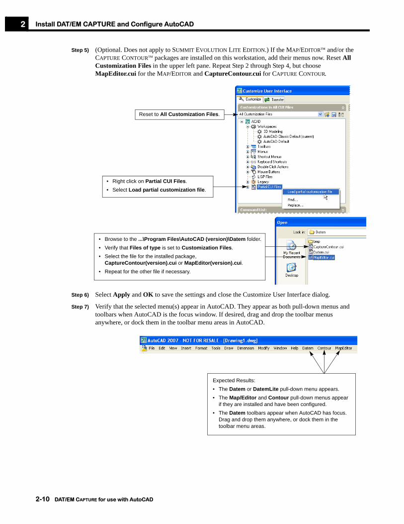
Step 5) (Optional. Does not apply to SUMMIT EVOLUTION LITE EDITION.) If the MAP/EDITOR™ and/or the CAPTURE CONTOUR™ packages are installed on this workstation, add their menus now. Reset All Customization Files in the upper left pane. Repeat Step 2 through Step 4, but choose MapEditor.cui for the MAP/EDITOR and CaptureContour.cui for CAPTURE CONTOUR.
Step 6) Select Apply and OK to save the settings and close the Customize User Interface dialog.
Step 7) Verify that the selected menu(s) appear in AutoCAD. They appear as both pull-down menus and toolbars when AutoCAD is the focus window. If desired, drag and drop the toolbar menus anywhere, or dock them in the toolbar menu areas in AutoCAD.
• Right click on Partial CUI Files.• Select Load partial customization file.
Reset to All Customization Files.
• Browse to the ...\Program Files\AutoCAD (version)\Datem folder.• Verify that Files of type is set to Customization Files.• Select the file for the installed package,
CaptureContour(version).cui or MapEditor(version).cui.• Repeat for the other file if necessary.
Expected Results:• The Datem or DatemLite pull-down menu appears.• The Map/Editor and Contour pull-down menus appear
if they are installed and have been configured.• The Datem toolbars appear when AutoCAD has focus.
Drag and drop them anywhere, or dock them in the toolbar menu areas.
2-10 DAT/EM CAPTURE for use with AutoCAD

Install DAT/EM CAPTURE and Configure AutoCAD 2
Review or Change the Application Loading MethodAn acad.rx file is provided with DAT/EM CAPTURE installation. This file contains a list of DAT/EM applications for AutoCAD to load every time it starts. However, some users prefer to change this installation default:
• To use the acad.rx file as it is originally installed, do nothing.
• To review or edit the acad.rx file, see “How to Load Applications from acad.rx” on page 2-11.
• To use the Startup Suite instead, see “How to Load Applications from the Startup Suite” on page 2-12.
• To disable loading, see “How to Prevent Automatic Loading, Then Load Manually” on page 2-13.
How to Load Applications from acad.rxAn acad.rx file is placed in the ...\ProgramFiles\AutoCAD(version)\Datem folder during DAT/EM CAPTURE software installation. As AutoCAD starts, it checks for an acad.rx file in the support file search path that was configured earlier in “Set the Support File Search Path and Pointing Device” on page 2-2. If the file exists, it automatically loads all the applications listed in the file.
You may wish to review or change the contents of the acad.rx file. Perform the following steps:
Step 1) Open the \Program Files\AutoCAD (version)\Datem\acad.rx file in any text editor such as Windows Notepad.
The DAT/EM application file names depend on the version of AutoCAD. Note that the names may not seem to match the version of AutoCAD, but that is normal. For example, files for both AutoCAD 2004 and AutoCAD 2006 are called (Filename)2004.arx. This simply means that there were no changes to the file for the higher version of AutoCAD.
Step 2) To add an application so that it loads automatically every time AutoCAD starts, enter its file name on a single line in the file. Some suggested files that may be included in acad.rx are (note that some applications are not provided with SUMMIT EVOLUTION LITE EDITION):
a.) Autolist(verison).arx, contains the autolist command.
b.) BlockRotate(verison).arx to rotate blocks in a drawing.
c.) Breaklinefilter(verison).arx contains the breaklinefilter command.
d.) Capture(verison).arx, contains the main DAT/EM CAPTURE interface and commands.
e.) CaptureContour(verison).arx, contains the CAPTURE CONTOUR option (if installed).
f.) CheckLineElevation(verison).arx, contains checklineelevation and other commands.
g.) Clenup(verison).arx, contains the cleanup command.
h.) ClipIt(verison).arx, contains the datclip command.
i.) DtmDistributor(verison).arx contains the dtmdistributor command.
j.) DtmEditor(verison).arx contains the dtmeditor command.
k.) DtmIt(verison).arx contains the dtmit command.
l.) MapEditor(verison).arx contains the MAP/EDITOR commands.
m.) Measure(verison).arx contains the measureheight and lineslope commands.
n.) Si(verison).arx, contains SUPER/IMPOSITION (if installed). If listing this application, list Capture(version).arx first, then list si(version).arx on the next line.
DAT/EM CAPTURE for use with AutoCAD 2-11

Install DAT/EM CAPTURE and Configure AutoCAD2
Step 3) To remove an application so that it does not load, delete the line containing that file name.
How to Load Applications from the Startup SuiteAn acad.rx file is placed in the ...\ProgramFiles\AutoCAD(version)\Datem folder during DAT/EM CAPTURE software installation. If AutoCAD finds the acad.rx file when it starts, it loads all the applications listed in the file. However, you may wish to use the AutoCAD Applications Startup Suite instead of acad.rx.
To use the Applications Startup Suite instead of the acad.rx file, perform the following steps:
Step 1) Rename ...\Program Files\Acad (version)\Datem\acad.rx file to acad.rx.deactivated. (Do not delete it, in case you want to use it again later.) After it is renamed, AutoCAD cannot find it.
Step 2) Start AutoCAD. Select Load Application from the Tools pull-down menu.
Step 3) Click the Contents button in the Startup Suite area.
Example acad.rx file to automatically load .arx files
Select Load Application from the Tools pull-down menu, then select the Contents button from the Startup Suite area.
• To add an application, select the Add button and choose the file.
• To delete an application, click on the file name to highlight it, then select Delete.
2-12 DAT/EM CAPTURE for use with AutoCAD

Install DAT/EM CAPTURE and Configure AutoCAD 2
Some suggested files that may be included in the Startup Suite are (note that some applications are not provided with SUMMIT EVOLUTION LITE EDITION):
a.) Autolist(verison).arx, contains the autolist command.
b.) BlockRotate(verison).arx to rotate blocks in a drawing.
c.) Breaklinefilter(verison).arx contains the breaklinefilter command.
d.) Capture(verison).arx, contains the main DAT/EM CAPTURE interface and commands.
e.) CaptureContour(verison).arx, contains the CAPTURE CONTOUR option (if installed).
f.) CheckLineElevation(verison).arx, contains checklineelevation and other commands.
g.) Cleanup(verison).arx, contains the cleanup command.
h.) ClipIt(verison).arx, contains the datclip command.
i.) DtmDistributor(verison).arx contains the dtmdistributor command.
j.) DtmEditor(verison).arx contains the dtmeditor command.
k.) DtmIt(verison).arx contains the dtmit command.
l.) MapEditor(verison).arx contains the MAP/EDITOR commands.
m.) Measure(verison).arx contains the measureheight, lineslope, and tinpolygons commands.
n.) MorphExporter(verison).arx contains the morphexporter command.
o.) Si(verison).arx, contains SUPER/IMPOSITION (if installed). If listing this application, list Capture(version).arx first, then list si(version).arx on the next line.
Step 4) When finished, close the Startup Suite and Load/Unload Applications boxes. The settings take effect the next time AutoCAD starts.
How to Prevent Automatic Loading, Then Load ManuallyThe user has a choice whether or not to load applications automatically. As a rule, if DAT/EM CAPTURE is used during the majority of AutoCAD sessions, then it is best to load the applications automatically. But if DAT/EM CAPTURE is not used often, you may wish to prevent automatic loading of some or all of its applications.
To prevent automatic application loading, perform the following steps:
Step 1) If currently using the acad.rx method to load applications:
• To stop using the acad.rx file, rename it to acad.rx.deactivated. (Do not delete it, in case you want to use it again later.) The file’s default installation location is: \Program Files\AutoCAD (version)\Datem\acad.rx.
• To continue using acad.rx, but to change the list of files it loads, edit \Program Files\AutoCAD (version)\Datem\acad.rx with any text editor such as Windows Notepad. See “How to Load Applications from acad.rx” on page 2-11.
Step 2) If using the Startup Suite to load applications, select Load Application from the Tools pull-down menu. Click the Contents button in the Startup Suite area. Delete any application names that should not be loaded when AutoCAD starts.
DAT/EM CAPTURE for use with AutoCAD 2-13

Install DAT/EM CAPTURE and Configure AutoCAD2
Step 3) DAT/EM CAPTURE applications may be loaded manually as follows.
Application How to load manually
capture(version).arx
si(version).arx
Available only if SUPER/IMPOSITION is installed.
All other DAT/EM arx files Use AutoCAD’s Tools > Load Application to load any of the other DAT/EM arx files found in the ...\Program Files\AutoCAD (version)\Datem folder.
Choose a method:• Select DAT/EM Startup from
the DAT/EM toolbar.• Select Load Capture from
the Datem pull-down menu.• Enter appload and load
capture(version).arx.
Choose a method:• Select Load S/I from the
Super/Imposition option of the Datem pull-down menu.
• Enter appload and select si(version).arx.
2-14 DAT/EM CAPTURE for use with AutoCAD

Chapter 3. Day-to-Day Use of DAT/EM CAPTURE 3
Chapter 3. Day-to-Day Use of DAT/EM CAPTURE
This chapter gives instructions and hints for digitizing, editing, and outputting with DAT/EM CAPTURE™.
How DAT/EM CAPTURE Affects the AutoCAD EnvironmentThere are several differences between using AutoCAD with a standard 2D digitizer and using AutoCAD with DAT/EM CAPTURE’s 3D digitizer. The most noticeable additions are as follows:
• With DAT/EM CAPTURE, there are two digitizers: the 2D mouse and the 3D stereoplotter. Read more about digitizer-related subjects in:
“Hints for Seeing the Cursor in a New Drawing File” on page 3-1“Cursor Control with System Mouse and Stereoplotter” on page 3-2
• The DAT/EM KEYPAD™, P-series tablet menu, pull-down AutoCAD menu, and toolbar menus all contain many useful DAT/EM CAPTURE utilities and digitizing aids. Read more about the menus in:
“Using the DAT/EM Menus” on page 3-2“Customizing the DAT/EM KEYPAD” on page 4-3
• DAT/EM CAPTURE provides commands to quickly digitize streamed and point-to-point 2D and 3D polylines and block symbols. Read more about these digitizing commands in:
“Digitizing Polylines with DAT/EM CAPTURE” on page 3-3“Digitizing Blocks with DAT/EM CAPTURE” on page 3-4Chapter 5, “DAT/EM CAPTURE Command Reference”
• In addition to the DAT/EM CAPTURE commands described in Chapter 5, all of the AutoCAD commands are available for mapping purposes. A good working knowledge of AutoCAD is valuable for efficient mapping. However, the beginning AutoCAD user will also be able use DAT/EM CAPTURE. Read more about helpful AutoCAD commands in:
“AutoCAD Commands that are Useful for Mapping Projects” on page 3-7“Using Layers to Separate Data” on page 3-7
Hints for Seeing the Cursor in a New Drawing FileIn a new drawing, the cursor may not immediately appear on the screen. The stereoplotter cursor position is in the model area, while the view displayed in a blank drawing file may not show the same coordinate range. When AutoCAD’s view is set to fit around the model area, the cursor will appear.
Even if the cursor is not on the screen, objects can still be digitized at the correct locations. AutoCAD is constantly updated with the current stereoplotter location, whether or not the cursor is in the graphics view.
To initially match the stereoplotter location and the AutoCAD display area:
1. Zoom with the stereoplotter
Zooming with the stereoplotter forces a new zoom center in AutoCAD. (Does not apply to analog stereoplotters.)
2. Turn on datpan
See “Datpan” on page 5-48.
DAT/EM CAPTURE for use with AutoCAD 3-1

Day-to-Day Use of DAT/EM CAPTURE3
Cursor Control with System Mouse and StereoplotterThe system mouse and the stereoplotter may be used alternately to move the cursor. Switching from one to the other is easy:
• For SUMMIT EVOLUTION LITE EDITION or when SUMMIT EVOLUTION is set to the System Mouse input device, right click in the main view to activate stereoplotter cursor control. Double right click to deactivate stereoplotter cursor control and switch back to regular system mouse mode.
• For all other stereoplotters and SUMMIT EVOLUTION digitizing devices, simply move the desired digitizer for it to obtain cursor control.
Using the DAT/EM MenusThere are two kinds of AutoCAD menus provided with DAT/EM CAPTURE. Instructions for configuring AutoCAD to display them appear in Chapter 3.
There is a DAT/EM pull-down menu and a set of toolbar menus:
:Most of the DAT/EM CAPTURE commands appear on the menus, as well as snap utilities and other tools. These commands are also available on the DAT/EM KEYPAD. The menus are provided as a method of quickly starting DAT/EM CAPTURE commands.
Toolbar menus
Pull-down menuFewer options appear for SUMMIT EVOLUTION LITE EDITION
3-2 DAT/EM CAPTURE for use with AutoCAD

Day-to-Day Use of DAT/EM CAPTURE 3
Getting Started with DAT/EM CAPTURE Digitizing CommandsWhen digitizing, the user may use any of the commands that come with AutoCAD plus the specialized mapping-specific commands that come with DAT/EM CAPTURE.
For example, a building could be digitized by starting AutoCAD’s 3dpoly command and digitizing each corner of the building, then entering the letter “C” to close the polyline. The result of this time-consuming 3dpoly command will be a building with sides that are not quite perpendicular. But DAT/EM CAPTURE offers several building commands that streamline the process, allow some corners to be calculated rather than digitized, square the building sides when necessary, and automatically close the polyline.
Each of the DAT/EM CAPTURE commands is described in detail in Chapter 5. The most commonly-used DAT/EM CAPTURE commands are described below in this chapter:
• To digitize elevation contours and other point-to-point or streamed polylines, see “Digitizing Polylines with DAT/EM CAPTURE” on page 3-3.
• To digitize mapping symbols using blocks, see “Digitizing Blocks with DAT/EM CAPTURE” on page 3-4.
Digitizing Polylines with DAT/EM CAPTUREThe DAT/EM CAPTURE system uses polylines for drawing linear features. In AutoCAD, there are two types of polylines, two- and three-dimensional (2D and 3D).
Two-dimensional polylines are entities consisting of a connected sequence of line and/or arc segments. The 2D polyline takes on the elevation of the first vertex.
• Use AutoCAD’s pline or DAT/EM’s autoarc2d to digitize point-to-point 2D polylines.
• Use capt2d to digitize in stream mode, with the first vertex’s elevation rounded off to the nearest contour interval. All the other vertices will remain set to this same elevation, even if the stereoplotter elevation is changed while digitizing. This command is most useful for digitizing elevation contours. See “Capt2d” on page 5-28.
Three-dimensional polylines are entities consisting of a connected sequence of line segments. Each vertex in a 3D polyline takes on the elevation of the digitizer (stereoplotter) at the time it was digitized.
• Use AutoCAD’s 3dpoly or DAT/EM’s autoarc3d to digitize point-to-point 3D polylines.
• Use capt3d for stream mode digitizing. This command is very useful for digitizing features that vary in elevation such as streams and field boundaries. It is also used to digitize break lines for use with contour generation packages. See “Capt3d” on page 5-30.
See the following sections for more information on digitizing polylines:
DAT/EM CAPTURE for use with AutoCAD 3-3

Day-to-Day Use of DAT/EM CAPTURE3
Capt2d Stream ModeCapt2d is a command that should be used when digitizing streamed curvilinear features with fixed elevations.
• Capt2d is primarily used to digitize elevation contours
The frequency of data points captured for the polyline is a function of the curvature angle and distance criteria input in the setup dialog box. See “Setup” on page 5-112.
When using capt2d, the elevation is automatically rounded to the nearest contour interval.
For instructions on using this command, see “Capt2d” on page 5-28.
Capt3d Stream ModeCapt3d stream mode is similar to the capt2d mode, except the elevation is exact, not rounded. Each elevation value may be different along the feature. Capt3d may be used when digitizing streamed curvilinear features with varying elevations such as:
• Streams
• Fences
• Break lines for later use with contour generation packages
The frequency of data points captured for the polyline is a function of the curvature angle and distance criteria input in the setup dialog box. See “Setup” on page 5-112.
For instructions on using this command, see “Capt3d” on page 5-30.
Digitizing Blocks with DAT/EM CAPTURESymbols are defined in AutoCAD as blocks, which are a set of individual entities grouped together into a compound object. Blocks can be made to represent standard features such as utility poles, swamp symbols, runway lights, control points, and mail boxes. Typical block symbols which might be used are as follows:
The default drawing file supplied with DAT/EM CAPTURE contains a set of blocks for mapping. Each of these blocks is matched to a key on the keypad overlay or menu diagram. The blocks and overlay can be customized for any mapping purposes. For instructions on customizing the default file blocks, see “New Blocks” on page 4-1.
To place symbols with the One- or Two-Shot modes, perform the following steps:
ANTENNA H-CONTROL PHOTO-CNTR SPOTX
CROSS HV-CONTROL POLE TREE
FENCETIK LIGHTP POST UTILITYP
GATE MAIL-BOX RLIGHT V-CONTROL
GRID MISC-OBJECT ROCK WINDSOCK
GUYANC PASS-POINT SIGN SIGN
3-4 DAT/EM CAPTURE for use with AutoCAD

Day-to-Day Use of DAT/EM CAPTURE 3
Step 1) Select a symbol key on the DAT/EM KEYPAD. DAT/EM KEYPAD keys typically set a layer, use -inssetup to set the name of the block, and activate the ins command.
Step 2) Digitize one or two points. The first point specifies the block insertion point. For the ins Rotate, ins Scale, and ins All options, the second point specifies an angle, a scale factor, or both. (One-shot blocks are placed according to the active rotation angle and map scale/symbol factor set with the setup dialog box.)
Step 3) Continue inserting blocks. The ins command remains active until another command is used.
Example: A series of power poles is to be plotted with the symbol ticks parallel to a street. The size of the UTILITYP block is correct using the setup map and scale factors.
Step 1) Select Utility Pole on the DAT/EM KEYPAD. This sets the UTILITY layer, uses -inssetup to set the block name to UTILITYP, and activates ins Rotate.
Step 2) Digitize a point at the base of a power pole.
Step 3) Move the stereoplotter parallel to the street and digitize a second point. The UTILITYP block is inserted at the digitized angle.
Step 4) Continue selecting pole bases and angles. More UTILITYP symbols are inserted.
Step 5) Select another command to cancel the symbol insertion mode.
One-Shot Mode (-Inssetup O and Ins)In One-Shot block insertion mode, the system will accept one digitized point at a time, with a beep sound each time the data switch is pressed. One-Shot is used especially for
• block placement• spot elevation placement
To activate this mode, enter -inssetup o, then set the symbol name with the ins command:
Command: -inssetupOne/Rotate/Scale/All: oCommand: insBlock name/? smalltree
Proceed to insert one or more blocks using the digitizing switch.
To set the block name and a layer for the block that is independent of the currently set AutoCAD layer, use the inssetup command instead of -inssetup. A dialog box allows all the settings to be made. However, when activating the command from the keypad, the -inssetup command should be used to avoid the dialog box.
Many of the symbol insertion keys on the keypad overlay or menu diagram activate the One-Shot mode and ins.
DAT/EM CAPTURE for use with AutoCAD 3-5

Day-to-Day Use of DAT/EM CAPTURE3
Two-Shot Mode (-Inssetup Rotate, Scale, and All)This mode is similar to One-Shot mode, but the system will accept two digitized points at a time. Two-Shot mode is used especially for:
• block placement with rotation angle specified• block placement with scale specified• block placement with both angle and scale specified
To set this mode, enter -inssetup, select Rotate, Scale, or All, then set the symbol name with the ins command. For example:
Command: -inssetupOne/Rotate/Scale/All: rCommand: insBlock name/? smalltree
Proceed to insert one or more blocks using the digitizing switch. The first digitized point will be the block insertion point, the second point will define the rotation angle, scale, or both.
To set the block name and a layer for the block that is independent of the currently set AutoCAD layer, use the inssetup command instead of -inssetup. A dialog box allows all the settings to be made. However, when activating the command from the keypad, the -inssetup command should be used to avoid the dialog box.
Some of the symbol insertion keys on the keypad overlay or menu diagram set the Two-Shot mode.
Regulating Block and Text SizeMany of the DAT/EM CAPTURE commands automatically insert blocks and text into the drawing. These commands must tell AutoCAD the block insertion size and the text size.
These routines use three variables to determine the size of text and blocks:
• Map scale
• Block scale factor
• Text scale factor
These variables appear in the DAT/EM Mapping Parameters dialog box, which may be activated with the setup command. (See “Setup” on page 5-112.)
Because the software is inserting the blocks using a scale factor, blocks should be created at a size of one ground unit in the template drawing file. (See “New Blocks” on page 4-1.)
3-6 DAT/EM CAPTURE for use with AutoCAD

Day-to-Day Use of DAT/EM CAPTURE 3
AutoCAD Commands that are Useful for Mapping ProjectsWhile digitizing and editing a map, all of AutoCAD's commands are available. AutoCAD has many commands, some of which will never be used in mapping projects. Other commands will be used extensively.
The following is a brief list of the most commonly used AutoCAD commands for mapping projects. The user is encouraged to review them in the AutoCAD Reference Manual or the AutoCAD on-line help.
Some AutoCAD commands have a direct application to mapping projects. Read more about them in:
• “Using Layers to Separate Data” on page 3-7
• “Referencing Edge Ties” on page 3-8
• “Editing the Drawing File” on page 3-8
• “Drawing Output” on page 3-8
Using Layers to Separate DataThe concept of AutoCAD layers is similar to that of transparent overlays used in drafting applications. Within AutoCAD, any number of layers may be defined, each containing a different type of information. Colors and linetypes can be assigned to each layer.
Please read the AutoCAD online help regarding layers.
Each different type of feature in a mapping project should be digitized on a unique layer. For example, place all paved roads on the ROAD-PAVED layer, and all unpaved roads on the ROAD-UNPAVED layer. Then when it comes time to extract information about one type of feature, it is very easy to freeze all layers except the layer in question.
A default acad.dwt drawing template file is supplied with DAT/EM CAPTURE. It contains a layer scheme for mapping. This scheme may be modified to suit the project. When making a layer scheme, try to make it detailed and flexible enough that it may be used on almost any type of project. Everyone concerned, including the map compiler, the editor, and the client will appreciate a consistent layering method.
Once the layer scheme is established, the layers should be added to the keypad overlay or menu diagram. The keypad overlay or menu diagram that comes with DAT/EM CAPTURE already has the layer items matched to the DAT/EM CAPTURE acad.dwt layer definitions.
When digitizing a feature, always set the layer first by selecting the layer name on the keypad or menu.
3dpoly extent pan undo
array insert pedit view
audit layer pline wblock
block lista
a. Consider using DAT/EM CAPTURE’S autolist.arx instead of list.
purge window
change mirror save xref
copy move text zoom
erase offset trim
The cancel function in AutoCAD is <Esc>.
DAT/EM CAPTURE for use with AutoCAD 3-7

Day-to-Day Use of DAT/EM CAPTURE3
Referencing Edge TiesWhen digitizing a model, it is useful to see what was digitized in the adjoining model, and be able to snap the new contours to the ones from the edge of the old file. Use reference files to accomplish this. Please review the xref command in AutoCAD’s online help.
Editing the Drawing FileEditing the drawing file after all features have been digitized is a very important step. The editor's task is to verify the data, join models together, break the project into map sheets, and add any additional textual or legend information.
The stereoplotter station can be used for editing if necessary; however, since compilation time and editing time often vary, and users sometimes want a more powerful computer for editing, it is more efficient to have a separate AutoCAD editing station. A commonly available tablet digitizer with a 16-button cursor is also a great editing help.
• The MAP/EDITOR, is a set of editing tools provided with DAT/EM CAPTURE.
• The autolist.arx utility speeds up getting information about objects. See page 5-20.
• The edbox command helps keep track of edited areas of a drawing. See “Edbox” on page 5-63.
All the AutoCAD commands may also be used for editing.
Drawing OutputAny ACAD drawing digitized using DAT/EM CAPTURE may be plotted like any other ACAD drawing. Refer to the AutoCAD documentation to become familiar with AutoCAD’s plotting software.
The xyzout command may be used to create ASCII files. The user is able to specify the output file format and the objects that should be exported. For instructions on exporting objects with xyzout, please see “Xyzout” on page 5-133.
DAT/EM CAPTURE’s morphexporter command may be used to write morphological data from the AutoCAD file to an INPHO .wnp file. See page 5-89.
3-8 DAT/EM CAPTURE for use with AutoCAD

Chapter 4. Customizing The System 4
Chapter 4. Customizing The System
The following DAT/EM CAPTURE™ software can be customized by the user:
• The template drawing with its layers and block symbols;
• The DAT/EM KEYPAD™ overlay and matching function list;
• The digitizer button definitions.
Customizing the Template Drawing The template drawing file is easily modified to contain a customized layer scheme and block symbols. When making a new default file, start with a copy of the acad.dwt file that is supplied with DAT/EM CAPTURE. This file already contains many helpful settings, and new layers and blocks may be added to it.
Note that when DAT/EM CAPTURE is installed, its acad.dwt overwrites AutoCAD’s version of acad.dwt.
A New Layer Scheme Changing the layer scheme is easy to do. First prepare a concise list of the new layers. This list should be extensive enough to be useful for any mapping project. The goal in developing a layer list is be able to use it for as many projects as possible. If the same default file is always used, both the company's employees and the clients will be able to rely on the consistent drawing format. A consistent layer scheme will also help tremendously if the files are to be translated later to another CAD system.
To input a new layer scheme, start with a copy of the acad.dwt file. Use the AutoCAD DDLMODES or LAYER commands to change and define new layers. See the AutoCAD documentation for help using these commands.
New BlocksNew blocks can be defined, or the existing ones from acad.dwt can be changed. When defining blocks, there are three very important goals:
• Make blocks the correct size, usually about 1 unit across (See page 4-2);
• Make blocks on the correct layer, usually layer 0 (See page 4-2);
• Make block components at zero elevation, Z=0.0 (See page 4-3);
• Define the new or edited block (See page 4-3).
The following sections contain some hints for creating blocks.
DAT/EM CAPTURE for use with AutoCAD 4-1

Customizing The System4
Creating a Block at the Correct SizeWhen using the DAT/EM CAPTURE symbol insertion utilities, blocks are inserted at a size determined by the current map scale and the symbol sizing factor entered in the setup dialog box. Scaling the blocks as they are inserted makes it possible to use the same block table for any scale map drawings. In other words, the same default drawing file may be used for maps drawn at 1:25, 1:500, and 1:1000.
Because the blocks are scaled at the moment they are inserted, there is one rule for block sizing:
Creating a Block on the Correct LayerA blocks retains properties of the layer on which it is inserted as well as those on which it was originally created. If the block was created on any layer other than the 0 (zero) layer, then both the layer of creation and the layer of insertion must be thawed in order to see the block.
As an example, a block called LIGHT-POLE can be created on a layer called LIGHT-POLE. If it is subsequently inserted on the UTILITY layer, then the block has properties of both the LIGHT-POLE and UTILITY layers. If the LIGHT-POLE layer was then frozen, the block would not appear on the screen. Both LIGHT-POLE and UTILITY must be thawed in order to see the block.
Because the blocks are inserted on the current layer, there is an optional rule for block layering. Please consider carefully the block’s purpose, and whether it should indeed be created on a separate layer.
The Block Size Rule:
Blocks defined in the default drawing file must be created at a size of one unit.
The exception to this is symbols that should appear oversized or undersized compared to other symbols in the file. In this case, they should be created at sizes such as 2 units or half a unit.
The Block Layer Rule (Optional):
Blocks defined in the default drawing file should be created on Layer 0.
The exception to this is blocks that should retain properties of the creation layer and the insertion layer.
4-2 DAT/EM CAPTURE for use with AutoCAD

Customizing The System 4
Creating a Block at the Correct ElevationBlocks are inserted at their creation elevation plus the current drawing elevation. To insert blocks at the stereoplotter’s exact current elevation, follow the block elevation rule:
Once the block components have been drawn, use the AutoCAD LIST command to make sure the elevation of each object is zero. If necessary, use the AutoCAD MOVE command to move an object to zero elevation.
Hint: If a block always appears at the wrong elevation, check its definition elevation by inserting the block with an asterisk (*) before the name. This inserts the symbol as individual exploded objects rather than as a block. Use AutoCAD’s LIST command to look at the elevation of each object. If necessary, move the components to zero elevation and redefine the block.
Defining a BlockUse the AutoCAD BLOCK command to define the block. Be sure the insertion point is chosen accurately. Most symbol blocks will have an insertion point exactly in the center of the symbol. Please see the AutoCAD Reference Manual for instructions on the BLOCK command.
Hint: It may be convenient to draw the blocks centered around the coordinate origin, (0,0,0). This makes it easy to define the block insertion point.
If a symbol is to be used only on a particular job, it can be generated in the individual drawing file. If it is to be added to the permanent list of symbols, then it should be created in the template drawing so that it is present every time a new file is started.
Once a new block symbol has been generated, a key for this symbol can be added to the keypad overlay or menu diagram.
Customizing the DAT/EM KEYPADPlease see the DAT/EM Keypad Operation Manual for instructions on customizing the keypad menu diagram.
Customizing the Foot Pedal and Button DefinitionsWith DAT/EM CAPTURE, the buttons and/or foot pedal(s) on the stereoplotter may be redefined. (All of the available buttons and foot pedals on the stereoplotter will be referred to collectively as “buttons.”)
To set button functions, use the buttons command or select the Edit Buttons option from the DAT/EM KEYPAD or from the Datem pull-down menu. See “Buttons” on page 5-27.
The Block Elevation Rule:
All the objects that make up the block must be at Z=0.0
DAT/EM CAPTURE for use with AutoCAD 4-3

Customizing The System4
4-4 DAT/EM CAPTURE for use with AutoCAD

Chapter 5. DAT/EM CAPTURE Command Reference 5
Chapter 5. DAT/EM CAPTURE Command Reference
This section contains the following:
• A brief listing of DAT/EM CAPTURE™ commands by category (Pages 5-1 through 5-10)
• A detailed alphabetical listing of all the commands (Pages 5-11 through 5-135)
Commands by Category
Block Commands
Block Commands Command Purpose
Autolist (Block Information) Show information about existing blocks.
BlockRotate (Rotate blocks) Rotate blocks based on their block name, layer, and/or location inside a closed polyline.
Brush (Brush patterning) Insert brush tick block symbols along a brush line.
Dep (Depression tick patterning) Insert depression tick block symbols along a depression contour.
Depression (Automatically find depression contours) Automatically find existing depression contours and either pattern them with blocks or change their layer.
Edbox (Edit boxes) Keep track of edited areas on a drawing.
Fence (Fence patterning) Insert fence tick block symbols along fence polylines.
Grail (Guard rail patterning) Insert guard rail block symbols along guard rail polylines.
Ins (Block or point digitizing) Quickly and repeatedly insert blocks or points using the settings made by inssetup or -inssetup.
Labelit (Elevation labels) Add elevation labels or blocks to polylines with options for rotation and polyline breaking.
Lc (Insert control point blocks) Insert control point block symbols at all the coordinate locations read from the currently active orientation control listing. (To insert selected points from a selected control file, see the lcf command.)
DAT/EM CAPTURE for use with AutoCAD 5-1
DAT/EM CAPTURE Command Reference5
Lcf (Insert control point blocks) Insert control point block symbols at selected control coordinate locations read from a selected control file. (To insert all points from the currently active orientation control file, see the lc command.)
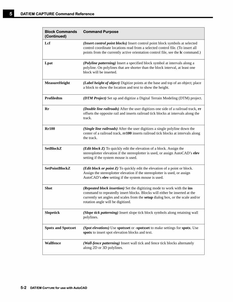
Lpat (Polyline patterning) Insert a specified block symbol at intervals along a polyline. On polylines that are shorter than the block interval, at least one block will be inserted.
MeasureHeight (Label height of object) Digitize points at the base and top of an object; place a block to show the location and text to show the height.
Profiledtm (DTM Project) Set up and digitize a Digital Terrain Modeling (DTM) project.
Rr (Double line railroads) After the user digitizes one side of a railroad track, rr offsets the opposite rail and inserts railroad tick blocks at intervals along the track.
Rr100 (Single line railroads) After the user digitizes a single polyline down the center of a railroad track, rr100 inserts railroad tick blocks at intervals along the track.
SetBlockZ (Edit block Z) To quickly edit the elevation of a block. Assign the stereoplotter elevation if the stereoplotter is used, or assign AutoCAD’s elev setting if the system mouse is used.
SetPointBlockZ (Edit block or point Z) To quickly edit the elevation of a point or block. Assign the stereoplotter elevation if the stereoplotter is used, or assign AutoCAD’s elev setting if the system mouse is used.
Shot (Repeated block insertion) Set the digitizing mode to work with the ins command to repeatedly insert blocks. Blocks will either be inserted at the currently set angles and scales from the setup dialog box, or the scale and/or rotation angle will be digitized.
Slopetick (Slope tick patterning) Insert slope tick block symbols along retaining wall polylines.
Spotx and Spotxset (Spot elevations) Use spotxset or -spotxset to make settings for spotx. Use spotx to insert spot elevation blocks and text.
Wallfence (Wall-fence patterning) Insert wall tick and fence tick blocks alternately along 2D or 3D polylines.
Block Commands (Continued)
Command Purpose
5-2 DAT/EM CAPTURE for use with AutoCAD

DAT/EM CAPTURE Command Reference 5
Digital Terrain Modeling and Related Commands
Xsect (Cross sectioning) Create a cross section project and collect (X,Y,Z) data along the cross sections.
Xyzin (Import from a file) Import blocks and other types of objects from an ASCII file.
Zcheck (Mark polyline intersections) Mark the point of intersection and the elevation difference between polylines where they intersect in the (X,Y) plane. See also crosscheck.
DTM and Related Commands
Command Purpose
BreaklineFilter (Change DTM points near breaklines) Change the layer of DTM points that are located near linework (breaklines).
Contour(See Chapter 6)
(Generate elevation contours with SCOP) Interpolate elevation contours using XYZ data from the AutoCAD® file for SCOP, which is a contour generation library by INPHO GmbH. This command also allows old contours to be deleted or moved. See Chapter 6.
DTMdistributor (Create a new DTM point distribution from other point sources) Combine two or more DTM point sets into a single set; to redistribute DTM points at a new grid interval.
DTMeditor (Edit point and block XYZs) To edit XYZ point data in the AutoCAD file.
DTMit (DTM Project) To set up a DTM project and digitize XYZ data on a grid.
Matchxyz(See Chapter 6)
(Import .DEM.XYZ file for SCOP) Import an INPHO MATCH-T-generated .dem.xyz file into an AutoCAD drawing. See Chapter 6.
Morphexporter (Export objects to .WNP file for SCOP) Export AutoCAD morphological objects into an INPHO MATCH-T .wnp file. See Chapter 6.
Profiledtm (DTM digitizing) Set up and digitize a Digital Terrain Modeling (DTM) project.
Xsect (Cross section digitizing) Create a cross section project and collect (X,Y,Z) data along the cross sections.
Block Commands (Continued)
Command Purpose
DAT/EM CAPTURE for use with AutoCAD 5-3

DAT/EM CAPTURE Command Reference5
Drawing/Editing Commands
Drawing/Editing Commands
Command Purpose
3doffset (Mainly roads with curves) Offset a 3D polyline so that the polylines look equidistant in the XY plane. The new polyline may also be offset by a constant elevation difference.
Autolist (Easier than LIST) Display object information as the cursor passes over the object. No button selections are necessary.
Autoarc2d (Roads with curves) Draw 2D polylines in point-to-point mode, adding arc segments wherever necessary, and continuing with straight segments when an arc is not required. autoarc2d is used primarily for digitizing roads with curves.
Autoarc3d (Roads with curves) Draw 3D polylines in point-to-point mode, simulating arc segments wherever necessary, and continuing with straight segments when an arc is not required. Autoarc3d is used primarily for digitizing roads with curves.
BlockRotateBlockRotateLast
(Rotate blocks) Rotate existing blocks based on their block name, layer, and/or location inside a closed polyline. BlockRotate activates a settings dialog; BlockRotateLast does not.
BreaklineFilter (Change DTM points near breaklines) Change the layer of DTM points that are located near linework (breaklines).
BuildingFrame (3D faces) Create 3D faces inside closed 3D polylines (usually buildings) and extend the sides to the ground.
Capt2d (Elevation contours) Digitize elevation contours. Capt2d creates 2D polylines with elevations rounded off to the nearest contour interval. Data capture may be toggled between stream and point-to-point digitizing.
Capt3d (3D streamed polylines) Allow convenient 3D polyline stream digitizing with the option to toggle to point-to-point digitizing mode.
Changescale (Convert drawing units) Change the units of the drawing by multiplying all object coordinates by a scale factor. Units available for conversion are meters, centimeters, millimeters, inches, feet, and furlongs.
CheckLineElevation (Find “flat” lines and polylines) To automatically find and change the layer of “flat” lines and polylines that have a total elevation range less than a given tolerance.
5-4 DAT/EM CAPTURE for use with AutoCAD

DAT/EM CAPTURE Command Reference 5
Cleanup (Fix zero-length polylines) To delete two-vertex, zero-length 3D polylines and/or to add 0.05 to the second vertex of any polyline that has the same Z value on every vertex.
DatClip (Clipping inside or outside) To clip objects inside or outside of polylines. Clipping may be specified either by object or by layer.
Contour(See Chapter 6)
(Generate elevation contours with SCOP) Interpolate elevation contours using XYZ data from the AutoCAD file for SCOP, which is a contour generation library by INPHO GmbH. This command also allows old contours to be deleted or moved. See Chapter 6.
Culvert (Culverts) Draw culverts based on the location of the culvert ends.
Curb (Curbs) Add the curb and gutter offsets to a single polyline representing a street edge or center line.
Depression (Automatically find depression contours) Automatically find existing depression contours and either pattern them with blocks or change their layer.
Dtmeditor(See Chapter 6)
(Edit XYZ data for SCOP) Edit XYZ data in the AutoCAD file so that the correct information can be sent to SCOP, which is a contour generation library by INPHO GmbH. See Chapter 6.
Editline (Edit and/or join polylines) To edit polylines. Choose:
1. End: Append to an end or replace an end section with a new series of straight segments and/or arcs;
2. Inner: Replace an interior section with a new series of straight segments and/or arcs;
3. Join: Join two polylines (or selected portions of two polylines) by drawing a new series of straight segments and/or arcs between them;
4. ShiftZ: Edit the elevation of individual vertices within a 3D polyline; edit the elevation of a 2D polyline.
Gridit (Coordinate grid and labels) Place objects (such as ticks, polylines, or blocks) on a grid. Options are given for grid labels and formats.
Interp (Contour interpolation) Interpolate intermediate elevation contours.
Joinitit(formerly called Join)
(Join polylines) Join two or more polylines together into one polyline.
Drawing/Editing Commands (Continued)
Command Purpose
DAT/EM CAPTURE for use with AutoCAD 5-5

DAT/EM CAPTURE Command Reference5
Lineslope (Measure slope grade) Digitize points at the bottom and top of a slope, place a line, and place a label indicating the percent grade.
MeasureHeight (Label height of object) Digitize points at the base and top of an object; place a block to show the location and text to show the height.
OpenUp (Open closed polylines) Open one or more closed polylines. Choose to either keep or remove the closing segment.
Opsqr2d (Building squaring, 2D orthogonal) Digitize buildings using 2D polylines and align them orthogonally to a specified angle.
Opsqr3d (Building squaring, 3D orthogonal) Digitize buildings using 3D polylines and align them orthogonally to a specified angle.
Profiledtm (DTM Project) Set up and digitize a Digital Terrain Modeling (DTM) project.
Psqr (Building squaring, 2D) Digitize and perform squaring on buildings and other man-made objects that have sides at right angles to each other. Psqr uses 2D polylines.
Psqr3d (Building squaring, 3D) Digitize and perform squaring on buildings and other man-made objects that have sides at right angles to each other. Psqr3d uses 3D polylines.
Reverse (Reverse vertex order) Reverse polyline vertex order.
Road (Road curb and gutter offsets) Starting with one road edge polyline, offset a complete set of curb and gutter polylines.
SetBlockZ (Edit block Z) To quickly edit the elevation of a block. Assign the stereoplotter elevation if the stereoplotter is used, or assign AutoCAD’s elev setting if the system mouse is used.
SetObjectZ (Edit object Z) To change the elevation of an object. For objects that have multiple vertices at varying elevations, it offsets each vertex by the elevation difference (instead of flattening all elevations to the same value).
SetPointBlockZ (Edit block or point Z) To quickly edit the elevation of a point or block. Assign the stereoplotter elevation if the stereoplotter is used, or assign AutoCAD’s elev setting if the system mouse is used.
Drawing/Editing Commands (Continued)
Command Purpose
5-6 DAT/EM CAPTURE for use with AutoCAD

DAT/EM CAPTURE Command Reference 5
Move Stereoplotter Commands
SetPointZ (Edit point Z) To quickly edit the elevation of a point. Assign the stereoplotter elevation if the stereoplotter is used, or assign AutoCAD’s elev setting if the system mouse is used.
Square (Square existing objects) Square the sides of existing polyline objects according to an angle tolerance.
Stairs (Stairs and landings) Draw stairways with options for elevation, landings, and aligning to buildings.
TinPolygons See “BuildingFrame” on page 5-25. The name has been changed.
Xyzin (Import from a file) Import objects from an ASCII file.
Move Commands Command Purpose
Contourdown Move the stereoplotter one contour interval down in elevation.
Contourup Move the stereoplotter one contour interval up in elevation.
Datemsnap Drive the stereoplotter to the (X,Y,Z) of a snapped-to point while 3dpoly, Autoarc3d, Capt3d, Opsqr3d, or Psqr3d is active.
Datmove Move the stereoplotter to a control point or user-specified coordinate.
Movebypick Move the stereoplotter to a point picked by the mouse.
Profiledtm (DTM Project) Set up and digitize a Digital Terrain Modeling (DTM) project.
Xsect (Cross sectioning) Create a cross section project and collect (X,Y,Z) data along the cross sections.
Zmove Move the stereoplotter to a user-specified elevation.
Drawing/Editing Commands (Continued)
Command Purpose
DAT/EM CAPTURE for use with AutoCAD 5-7

DAT/EM CAPTURE Command Reference5
Output Commands
Search Commands
Output Commands
Command Purpose
Morphexporter Export AutoCAD morphological objects into an Inpho GmbH-format .wnp file. This file may then be used by Inpho’s MATCH-T software.
Xyzout Select objects and export them to an ASCII output file.
Search Commands
Command Purpose
Autolist (Easier than LIST) Display object information as the cursor passes over the object. No button selections are necessary.
CheckLineElevation (Find “flat” lines and polylines) To automatically find and change the layer of “flat” lines and polylines that have an elevation range less than a tolerance.
Cleanup (Find and fix zero-length polylines) To delete two-vertex, zero-length 3D polylines and/or to add 0.05 to the second vertex of any polyline that has the same Z value on every vertex.
Crosscheck (Mark polyline intersections) Search for crossing or nearly crossing polylines and mark the intersections or near-intersections.
Depression (Automatically find depression contours) Automatically find existing depression contours and either pattern them with blocks or change their layer.
Xyzout (Export objects) Select objects and export them to an ASCII output file.
Zcheck (Mark polyline intersections) Mark the point of intersection and the elevation difference between polylines where they intersect in the (X,Y) plane.
5-8 DAT/EM CAPTURE for use with AutoCAD

DAT/EM CAPTURE Command Reference 5
Settings Commands
SUPER/IMPOSITION Commands
Text Insertion Commands
Settings Commands
Command Purpose
Buttons (Switch programming) Edit the functions of the foot switches and other stereoplotter buttons.
Inssetup and -Inssetup
(Settings for ins) Make settings for the ins command. Inssetup activates a dialog box, but -inssetup does not.
Setup (General settings) Change the settings listed in the DAT/EM capture parameters dialog box.
SUPER/IMPOSITION Commands
Command Purpose
Si (SUPER/IMPOSITION™ commands) Activate the AutoCAD-specific SUPER/IMPOSITION options.
Text Insertion Commands
Command Purpose
Gridit (Coordinate grid and labels) Place objects (such as ticks, polylines, or blocks) on a grid. Options are given for grid labels and formats.
Labelit (Elevation labels) Add elevation labels or blocks to polylines with options for rotation and polyline breaking.
Lineslope (Measure slope grade) Digitize points at the bottom and top of a slope, place a line, and place a label indicating the percent grade.
MeasureHeight (Label height of object) Digitize points at the base and top of an object; place a block to show the location and text to show the height.
Profiledtm (DTM Project) Set up and digitize a Digital Terrain Modeling (DTM) project.
DAT/EM CAPTURE for use with AutoCAD 5-9

DAT/EM CAPTURE Command Reference5
View Commands
Commands by Alphabetical ListingThe remainder of this chapter contains an alphabetical command listing.
Spotx and Spotxset (Spot elevations) Use spotxset to make settings for spotx. Use spotx to insert spot elevation blocks and text.
Xyzin (Import from a file) Import text and other types of objects from an ASCII file.
Zcheck (Mark polyline intersections) Mark the point of intersection and the elevation difference between polylines where they intersect in the (X,Y) plane. See also Crosscheck.
View Commands Command Purpose
Closergview Change the AutoCAD view to (0,1,0) for a close-range project or to (0,0,1) for an aerial project.
Datpan Perform a transparent view zoom whenever the stereoplotter’s cursor approaches the edge of the video screen.
Datemrotate Rotate the screen view without changing the coordinates of the drawing. It is often used so north will appear up on the screen. To remove the rotation, use unrotatescreen.
Unrotatescreen Remove the screen rotation caused by Datemrotate.
Text Insertion Commands (Continued)
Command Purpose
5-10 DAT/EM CAPTURE for use with AutoCAD

DAT/EM CAPTURE Command Reference3
do
ffse
t5
The 3doffset command offers a convenient way to offset 3D polylines for mapping purposes. The resulting polyline is an even distance from the original polyline when viewed in the XY plane, and has vertex elevations similar to the ones on the original polyline. A constant elevation offset may also be specified. When using 3D polylines, it is better to use DAT/EM’s 3doffset than AutoCAD’s offset command.
To use the 3doffset command, perform the following steps:
Step 1) Before starting the command, prepare the original poly16
Step 2) line. In order to know the left and right sides of the polyline, find out which end of the polyline contains the first vertex and which contains the last.
Step 3) Start the 3doffset command:
Command: 3doffsetSelect a polyline <Last>:
Step 4) Select any polyline or accept the default to use the last digitized object.
Measure offset? No/<Yes>:
Step 5) Choose either to digitize the offset distance or to enter the distance using the keyboard:
a.) To select the offset distance with the digitizer, enter Yes. To the “Pick an offset point” prompt, carefully position the digitizer (mouse or stereoplotter) at an XYZ position that would be on the new offset polyline. That is, the digitized point should define both the side of the offset and the XY and Z distances from the original polyline. Note that this option can be accessed more quickly from the 3doffsetmeasure command. See “3doffsetmeasure” on page 5-12.
b.) To enter the offset distances using the keyboard, enter No. Three more prompts appear:
Side for new line Right/<Left>:
Select a point to the side where the new offset polyline should appear.
Enter an xy offset distance <>:
Either accept the default value or enter the distance in ground units from the original polyline to the new polyline.
Enter a z offset value <>:
Enter the elevation offset. This number is entered in ground units, and may be positive or negative. For example, if -5 is entered, each vertex on the new polyline will be set 5 units less than the elevation of the nearest point on the original polyline.
The new polyline is drawn. The number of vertices found in the original polyline is reported.
3doffsetPurpose: To offset a 3D polyline so that the polylines look equidistant in the XY plane. The new polyline may also be
offset by a constant elevation difference.
See also: 3doffsetmeasure, Curb, Road
x
y
5-11 DAT/EM CAPTURE for use with AutoCAD

DAT/EM CAPTURE Command Reference3
do
ffse
tme
asu
re5
The 3doffsetmeasure command is the same as the “Measure offset” option of 3doffset. The 3doffsetmeasure skips 3doffset’s prompt that offers the user to enter the offset on the keyboard.
To use the 3doffsetmeasure command, perform the following steps:
Step 1) Start the 3doffsetmeasure command:
Command: 3doffsetmeasureSelect a polyline <Last>:
Step 2) Select any polyline or accept the default to use the last digitized object.
Pick and offset point
Step 3) Carefully position the digitizer (mouse or stereoplotter) at an XYZ position that would be on the new offset polyline. That is, the digitized point should define both the side of the offset and the XY and Z distances from the original polyline.
The new polyline is drawn.
3doffsetmeasurePurpose: To offset a 3D polyline so that the polylines look equidistant in the XY plane. This command is the same as
the “Measure offset” option of 3doffset.
See also: 3doffset, Curb, Road
x
y
5-12 DAT/EM CAPTURE for use with AutoCAD

DAT/EM CAPTURE Command ReferenceA
rc3
d5
Arc3d draws a 3D polyline that alternates between point-to-point mode and arc mode. Arc3d is used primarily for close range projects. For aerial projects, use autoarc3d (page 5-17) instead:
When simulating an arc, Arc3d asks the user to choose the endpoints and the center point of the arc. Vertices, or strokes, are added to the 3D polyline to simulate an arc shape.
To use Arc3d, perform the following steps:
Step 1) Select a DAT/EM KEYPAD™ key or menu item for autoarc3d, or enter command:
Command: arc3dFrom point/Stroke:
Arc3dPurpose: To draw a 3D polyline that alternates between point-to-point mode and arc mode. The “arcs” are true 3D arcs
that are simulated by line segments. This command is useful for close range projects.
An “arc” drawn by the command... Arc3d Autoarc3d (page 5-17)
Simulates a true 3D arc? Yes. No. The result appears to be an arc only when viewed on the XY plane.
Simulates an arc with line segments? Yes. True 3D arcs are not possible in AutoCAD.
Yes. True 3D arcs are not possible in AutoCAD.
Varies in elevation? Yes. Elevations are set so that the simulated arc appears to be part of a circle in 3D space.
Yes. Elevations are interpolated between the three digitized points. The elevations are based on the distance traveled in the XY plane.
Good for Close Range projects? Yes. No.
Good for Aerial Projects? No. Yes.
(1,1,1)
(5,3.5,10)
(7,8,3)
(1,1,1)
(7,8,3)
(5,3.5,10)
• Arc3d simulates a true 3D arc in space. It appears to be part of a circle in 3D space; however, it can look distorted when viewed straight down on the XY plane.
• Autoarc3d simulates an arc in the XY plane and then varies the elevation along it. It looks like part of a circle only when viewed straight down on the XY plane.
ARC3D
ARC3D
AUTOARC3D AUTOARC3D
5-13 DAT/EM CAPTURE for use with AutoCAD

DAT/EM CAPTURE Command ReferenceA
rc3
d5
Step 2) 3D arcs are simulated using a series of straight segments, or strokes. If set small enough, the segments appear to be an arc at the plot scale. To change the number of strokes, enter S and enter a new number:
Enter number of segments in a circle <100>:
Step 3) For this first point, either digitize a point, or enter a snapping command such as endp or ins and snap to an object. Depending on the current arc mode, the next prompt will be one of the following:
Line to point /Undo/Close/Arc/Stroke/RetroSecond pt of Arc /Undo/Close/Line/Stroke:
To this prompt, there are several options:
Action Arc3d Result
• Press the digitizing switch
Digitize a point on the polyline. Straight segment mode is the default setting when arc3d starts.
• U Remove the last vertex and continue.
• C Close and finish the polyline.
• A Start a 3-point simulated arc. The 3-point arc mode is started. Pick a point along the arc, then pick the end point of the arc. After the arc is complete, arc digitizing mode remains active until L is entered.
• L Start a straight segment. Straight segment digitizing mode remains active until A or is entered.
• S Enter a new number of circle segments for simulating 3D arcs.
• R Change the last two segments (three vertices) to a three-point arc.
• Enter an AutoCAD snapping command such as ENDP
Snap to another object and continue.
• <Enter> or • “ ” (spacebar) button
hit once.
Finish the polyline without closing, leaving arc3d active and ready to digitize the next polyline.
• <Enter><Enter> or • “ ” (spacebar) button
hit twice or• <Esc><Esc>
Finish the polyline without closing and end the arc3d command.
5-14 DAT/EM CAPTURE for use with AutoCAD

DAT/EM CAPTURE Command ReferenceA
uto
arc
2d
5
Autoarc2d uses 2D polylines in a series of straight segments and arcs.
To use autoarc2d, perform the following steps:
Step 1) (Optional) Set a digitizer button to toggle the mode. Set Type=User CAD and Action=A (“A” followed by a blank space character). See “Buttons” on page 5-27 for further instructions. This button may also be used for the autoarc3d command (page 5-17)
Step 2) Select the keypad or menu item for autoarc2d, or type the command and choose the option:
Command: autoarc2d
Step 3) To the first “From Point” prompt, either pick a point or enter a snapping command such as endp or ins and snap to an object.
Step 4) Depending on the current arc or line mode, the next prompt will be one of the following:
Arc/3ptArc/Undo/Close/Retro<Endpoint of line>:Line/3ptArc/Undo/Close/<Endpoint of line>:
To these prompts, there are several options:
Autoarc2dPurpose: To draw 2D polylines in point-to-point mode, adding arc segments wherever necessary, and continuing with
straight segments when an arc is not required. autoarc2d is used primarily for digitizing roads with curves.
5-15 DAT/EM CAPTURE for use with AutoCAD
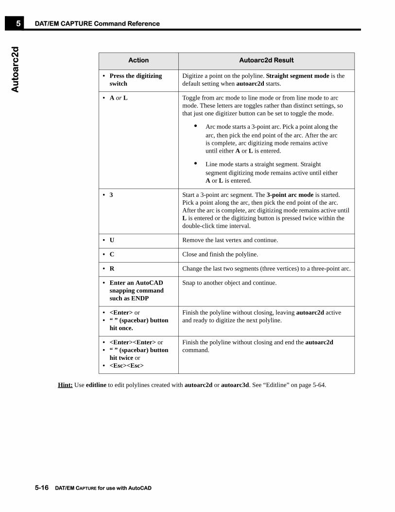
DAT/EM CAPTURE Command ReferenceA
uto
arc
2d
5
Hint: Use editline to edit polylines created with autoarc2d or autoarc3d. See “Editline” on page 5-64.
Action Autoarc2d Result
• Press the digitizing switch
Digitize a point on the polyline. Straight segment mode is the default setting when autoarc2d starts.
• A or L Toggle from arc mode to line mode or from line mode to arc mode. These letters are toggles rather than distinct settings, so that just one digitizer button can be set to toggle the mode.
• Arc mode starts a 3-point arc. Pick a point along the arc, then pick the end point of the arc. After the arc is complete, arc digitizing mode remains active until either A or L is entered.
• Line mode starts a straight segment. Straight segment digitizing mode remains active until either A or L is entered.
• 3 Start a 3-point arc segment. The 3-point arc mode is started. Pick a point along the arc, then pick the end point of the arc. After the arc is complete, arc digitizing mode remains active until L is entered or the digitizing button is pressed twice within the double-click time interval.
• U Remove the last vertex and continue.
• C Close and finish the polyline.
• R Change the last two segments (three vertices) to a three-point arc.
• Enter an AutoCAD snapping command such as ENDP
Snap to another object and continue.
• <Enter> or • “ ” (spacebar) button
hit once.
Finish the polyline without closing, leaving autoarc2d active and ready to digitize the next polyline.
• <Enter><Enter> or • “ ” (spacebar) button
hit twice or• <Esc><Esc>
Finish the polyline without closing and end the autoarc2d command.
5-16 DAT/EM CAPTURE for use with AutoCAD

DAT/EM CAPTURE Command ReferenceA
uto
arc
3d
5
Autoarc3d draws a 3D polyline that alternates between point-to-point mode and arc mode. Autoarc3d is used primarily for digitizing roads that contain curves. For close range projects, use arc3d (See “Arc3d” on page 5-13):
Autoarc3dPurpose: To draw a 3D polyline that alternates between point-to-point mode and arc mode. The “arcs” are simulated by
line segments. The result is intended to be viewed in the XY plane. Datemsnap may be used with autoarc3d.
An “arc” drawn by the command... Arc3d (page 5-13) Autoarc3d
Simulates a true 3D arc? Yes. No. The result appears to be an arc only when viewed in the XY plane.
Simulates an arc with line segments? Yes. True 3D arcs are not possible in AutoCAD.
Yes. True 3D arcs are not possible in AutoCAD.
Varies in elevation? Yes. Elevations are set so that the simulated arc appears to be part of a circle in 3D space.
Yes. Elevations are interpolated between the three digitized points. The elevations are based on the distance traveled in the XY plane.
Good for Close Range projects? Yes. No.
Good for Aerial Projects? No. Yes.
(1,1,1)
(5,3.5,10)
(7,8,3)
(1,1,1)
(7,8,3)
(5,3.5,10)
• Arc3d simulates a true 3D arc in space. It appears to be part of a circle in 3D space; however, it can look distorted when viewed straight down on the XY plane.
• Autoarc3d simulates an arc in the XY plane and then varies the elevation along it. It looks like part of a circle only when viewed straight down on the XY plane.
ARC3D
ARC3D
AUTOARC3D AUTOARC3D
XY PlaneSomewhere in space
5-17 DAT/EM CAPTURE for use with AutoCAD

DAT/EM CAPTURE Command ReferenceA
uto
arc
3d
5
When simulating an arc, autoarc3d asks the user to choose the endpoints and the center point of the arc. Vertices, or strokes, are added to the 3D polyline to simulate an arc shape. These vertices vary gradually in elevation from the elevation of the first point to the middle point, and then again from the middle point to the end point.
To use autoarc3d, perform the following steps:
Step 1) (Optional) If moving the analytical or digital stereoplotter to the (X,Y,Z) of a snapped-to point is desired, turn on Datemsnap and any desired ‘osnap snaps. (See “Datemsnap” on page 5-46).
• Note that Datemsnap will override autoarc3d’s own Plotter z[OFF] 2D snap setting.
• There is a difference between Datemsnap and autoarc3d’s own Plotter z[ON] setting. Datemsnap will drive the stereoplotter to the 3D snap, but Plotter z[ON] will allow the 3D snap without moving the stereoplotter to the point.
Step 2) (Optional) Set a digitizer button to toggle the mode. Set Type=User CAD and Action=A (“A” followed by a blank space character). See “Buttons” on page 5-27 for further instructions.
Step 3) Select the keypad or menu item for autoarc3d, or type the command and choose the option:
Command: autoarc3dFrom point/Stroke/Plotter z[OFF]:
Step 4) 3D arcs are simulated using a series of straight segments, or strokes. If set small enough, the segments appear to be an arc at the plot scale. To change the number of strokes, enter S and enter a new number:
Enter number of segments in a circle for 3d arc simulation <64>:
Step 5) If snapping to other objects when Datemsnap is off, enter P to toggle the setting as follows:
• To snap to the X,Y location of the other object, but use the stereoplotter’s elevation, turn [on] the stereoplotter Z setting.
• To snap to the X,Y, and Z location of the other object, turn [off] the stereoplotter Z setting.
Step 6) For this first point, either pick a point, or enter a snapping command such as endp or ins and snap to an object. Depending on the current arc mode, the next prompt will be one of the following:
Line to point /Undo/Close/Arc/Stroke/Retro/Plotter z[OFF]:Line to point /Undo/Close/Line/Stroke/Retro/Plotter z[OFF]:
To this prompt, there are several options:
Action Autoarc3d Result
• Press the digitizing switch
Digitize a point. Note that Straight segment mode is the default setting when autoarc3d starts.
• U Remove the last vertex and continue.
• C Close and finish the polyline.
5-18 DAT/EM CAPTURE for use with AutoCAD

DAT/EM CAPTURE Command ReferenceA
uto
arc
3d
5
Hint: Use editline to edit polylines created with autoarc2d or autoarc3d. See “Editline” on page 5-64.
• A or L Toggle from arc mode to line mode or from line mode to arc mode. These letters are toggles rather than distinct settings, so that just one digitizer button can be set to toggle the mode.
• Arc mode starts a 3-point simulated arc segment. Pick a point along the arc, then pick the end point of the arc. After the arc is complete, arc digitizing mode remains active until either A or L is entered.
• Line mode starts a straight segment. Straight segment digitizing mode remains active until either A or L is entered.
• S Enter a new number of circle segments for simulating 3D arcs.
• R Change the last two segments (three vertices) to a three-point arc.
• P Toggle the elevation setting to be used when snapping to other objects:• To snap to the X,Y location of the other object, but use the
stereoplotter’s elevation, turn [on] the stereoplotter Z setting. (Datemsnap must be off for this to work. If Datemsnap is on, the snap will always be 3D.)
• To snap to the X,Y, and Z location of the other object, turn [off] the stereoplotter Z setting. (If Datemsnap is on, the stereoplotter will also move to the snapped-to point.)
• Enter an AutoCAD snapping command such as ENDP
Snap to another object and continue. (If Datemsnap is on, the stereoplotter will move to the (X,Y,Z) location of the snapped-to point.)
• <Enter> or • “ ” (spacebar) button
hit once.
Finish the polyline without closing, leaving autoarc3d active and ready to digitize the next polyline.
• <Enter><Enter> or • “ ” (spacebar) key hit
twice or• <Esc><Esc>
Finish the polyline without closing and end the autoarc3d command.
Action Autoarc3d Result
5-19 DAT/EM CAPTURE for use with AutoCAD

DAT/EM CAPTURE Command ReferenceA
uto
list
5
To use autolist.arx, perform the following steps:
Step 1) Select Autolist from the Editing option of the Datem pull-down menu in AutoCAD.
Step 2) When it is loaded, a small dialog box appears. To customize the contents of the list, select Settings.
Step 3) If it is not already highlighted, select the ON button on the Autolist box.
Step 4) Place the system mouse cursor over an object in the AutoCAD drawing. A list of the object’s properties appears next to the cursor. Note that the system mouse must be used; the stereoplotter cursor does not activate the Autolist display.
Step 5) Select OFF at any time to turn off the Autolist command. The Autolist dialog box remains on the screen. It may be turned ON again any time.
AutolistPurpose: To display object information as the system cursor passes over the object. No button selections are necessary.
This is a separate .arx command activated by autolist.arx.
As the system cursor moves over an object in the AutoCAD drawing, a list of the object’s properties appears.
Select Autolist from the Editing Tools option of the Datem pull-down menu.
• To turn on the automatic listing, select ON.
• Automatic listing will turn OFF whenever another command is started.
To customize the contents of the list, select Settings. Select list items.
Select the list text size.
5-20 DAT/EM CAPTURE for use with AutoCAD

DAT/EM CAPTURE Command ReferenceB
lock
Ro
tate
5
Perform the following steps:
Step 1) Load the ...Program Files\AutoCAD (version)\Datem\BlockRotate(version).arx file. To load the file, use the appload command or select Load Application from AutoCAD’s Tools pull-down menu.
Step 2) If blocks will be selected based on their location inside one or more polygons (closed polylines), then either verify that the polylines exist or draw them now. Blockrotate performs an XY search only; the elevation of the polylines does not matter.
Step 3) To use the dialog box, start the blockrotate command and make settings:
Command: blockrotate
Step 4) Or, to run the command using the most recent settings, but without activating the dialog box, enter the BlockRotateLast command:
Command: blockrotatelast
The command runs without asking for input or settings.
BlockRotateBlockRotateLast
Purpose: To rotate existing blocks based on their block name, layer, and/or location inside a closed polyline. BlockRotate activates a settings dialog; BlockRotateLast does not.
Three runs of BlockRotate
Note: If no layers are checked, the layer filter is disabled.
Choose a rotation method:• Absolute Rotation checked on:
Set the blocks’ rotation angle to the selected angle.
• Absolute Rotation not checked: The new angle is added to each block’s original angle.
Note: If no block names are checked, the block name filter is disabled.
Hint: To rotate all blocks inside polygons, set a Within Polygons layer and do not check any block names or layer names.
Hint: To disable the Within Polygons filter, set it to (None Selected), which is the first option on its pop-down menu.
Enter the new absolute angle or angle offset in degrees. Select Apply to run the command.
5-21 DAT/EM CAPTURE for use with AutoCAD

DAT/EM CAPTURE Command ReferenceB
rea
klin
eF
ilte
r5
The breaklinefilter command changes the layer of DTM points or blocks that are located near linework. To use breaklinefilter, perform the following steps:
Step 1) Prepare the DTM points and/or blocks and the polylines that will be used with breaklinefilter.
Step 2) Start the breaklinefilter command:
Command: breaklinefilter
Step 3) Begin to make selections in the Break Line Filter dialog:
BreaklineFilterPurpose: Change the layer of DTM points or blocks that are located near linework (breaklines).
Breaklinefilter+
freeze the move-to layer
Specify the layers or objects to be used as breaklines. One or both of the following methods may be used:• To select individual objects, click on the Objects
radio button. Click on the Begin selecting button. Select objects in the file, then press the <Enter> key to return to the dialog.
• To select objects by layer, click on the Layers radio button. Either click on the Begin selecting button to select objects for layer matching, or select a layer name from the pop-down list and click the Add layer to list button.
Note: All selected objects and layers will be used during processing. Clicking the Objects radio button does not exclude Layers and vice versa.
Specify the layers of the DTM points and/or blocks. To select a DTM point or block for layer matching, click on the Begin selecting button. Select points and/or blocks on each DTM layer, then press the <Enter> key to return to the dialog. To select layers by name, select a layer from the pop-down list and click the Add layer to list button.
5-22 DAT/EM CAPTURE for use with AutoCAD

DAT/EM CAPTURE Command ReferenceB
rea
klin
eF
ilte
r5
Step 4) Continue to make selections in the Break Line Filter dialog:
Step 5) Select Process. At the end of processing, a message box appears to display the number of points and blocks moved to the Move To Layer.
After the points and/or blocks have been moved to the Move To Layer, they may be selected separately from the remaining DTM points or blocks. They may be deleted or saved according to the user’s preference.
Specify the distance tolerances. A point or block is moved to the Move to Layer if the following are true:• Its XY ≤ Horizontal Distance from
the XY of the breakline, AND• Its Z ≥ Vertical Distance from the Z
of the breakline, as long as Vertical Distance is not 0 (zero).
Note that Vertical Distance is ignored if it is set to 0 (zero).
DTM points and blocks that fall within the Horizontal Distance or are outside the Vertical Distance of the breakline are moved to the Move To Layer.
5-23 DAT/EM CAPTURE for use with AutoCAD

DAT/EM CAPTURE Command ReferenceB
rush
5
Before starting any block patterning command, perform the following:
• Set the layer for the new blocks.
• Use the setup command to verify the Block scale factor and Block rotation angle and select the desired Planimetric Patterning setting.
To insert ticks on brush lines, type brush and choose the 2D or 3D polylines to pattern:
Command: brushSelect objects <Last>:
Choose one or more polylines or enter L to use the most recently digitized object. The computer then prompts:
(T)oggle side/(B)lock Scale=#/(P)attern Dist=# <Enter>:
The blocks appear visually along the polyline, but are not permanent objects until <Enter> is pressed. Several options may be changed before the blocks are actually inserted:
• To instantly change the direction of the blocks, enter T.
• To change the block size, enter B and set a new scale.
• To change the block pattern spacing, enter P and set the new spacing in ground units.
• When the blocks are correct, press <Enter> to accept them.
The file is searched for the block BTICKR or BTICKL. If the block does not already exist, it is created. The ticks are then inserted at intervals along the polylines.
BrushPurpose: To insert brush tick block symbols along a polyline representing a brush line.
All blocks inserted at the same elevation!If on (checked), all the blocks will be inserted as follows:•For 2D polylines: at the polyline’s Z•For 3D polylines: at Z=0 and evenly spaced in the (X,Y) plane.
Blocks inserted at the polyline elevation.If off (not checked), the blocks will be inserted at the polyline Z. On 3D polylines, the elevation will be interpolated along the polyline segment.
(from the setup box)
5-24 DAT/EM CAPTURE for use with AutoCAD

DAT/EM CAPTURE Command ReferenceB
uild
ing
Fra
me
5
The BuildingFrame command creates either triangular or rectangular 3D faces inside existing closed 3D polylines (usually buildings) and extends the sides to the ground. This command may be useful to define building roof and wall planes. It is also useful for displaying shaded building structures in SUMMIT EVOLUTION’s 3D Vector Split Window.
For simplicity, all closed polylines will be called “buildings”. This is usually a closed polyline digitized along the roof of a building.
To use the BuildingFrame command, perform the following steps:
Step 1) If necessary, load the ...Program Files\AutoCAD (version)\Datem\Measure(version).arx file. To load the file, use the appload command or select Load Application from AutoCAD’s Tools menu.
Step 2) Start the BuildingFrame command and make settings.
Command: buildingframe
Step 3) Select Apply to run the command. Run again with different input, or close the dialog when finished.
BuildingFrame(Formerly TinPolygons)
Purpose: Create 3D faces inside closed 3D polylines (usually buildings) and extend the sides to the ground.
Results of BuildingFrame viewed in SUMMIT EVOLUTION’s 3D Vector Split View. (The Split View’s Light 3D faces setting is off to the left, on to the right).
Choose a selection method:• To add 3D faces to all
buildings on one or more layers, check on the layers.
• Or, check on Use selected and use the selection tool to pick one or more buildings.
Check on Extrude to extend the building “to the ground” in the Z direction. For buildings, this is useful to make walls -- 3D faces -- from the roof to the ground. Choose an Extrude option to determine the ground elevation:• Set Use ground level to extrude
each side down to the same single elevation value. Enter the value or select Current Z to obtain the stereoplotter’s current Z value.
• Set use DTM files to extrude down to a surface determined by elevation point files, such as a LiDAR files. Use the Select button to browse for one or more files.
• Extrude with Rectangles on creates rectangular 3D faces; off creates triangular 3D faces.
Choose a TIN method:• Choose Make complex... for
nested polygons that belong to the same object. For example, a higher roof line inside a lower roof line. This setting makes sure that the inner segments are used as 3D face edges. This is known as Constrained Delaney Triangulation.
• Choose Make simple... to treat every building as a separate object. No searching is done for nested polygons. Set Triangles (3D Faces) to
a layer for the new 3D faces.
5-25 DAT/EM CAPTURE for use with AutoCAD

DAT/EM CAPTURE Command ReferenceB
uild
ing
Fra
me
5
SUMMIT EVOLUTION’s 3D Vector Split View and its Light 3D Faces option are useful for viewing the results.
5-26 DAT/EM CAPTURE for use with AutoCAD

DAT/EM CAPTURE Command ReferenceB
utt
on
s5
The Button Manager application sets the actions of the 3D cursor device buttons and/or foot pedal(s). The button manager command activates the application, which runs outside of AutoCAD.
Complete instructions for the Button Manager appear in the SUMMIT EVOLUTION Operation Manual or the supplemental documentation supplied with DAT/EM CAPTURE for analog and analytical stereoplotters.
ButtonsPurpose: To activate the Button Manager application to set the functions of the stereoplotter cursor device’s buttons and
switches.
5-27 DAT/EM CAPTURE for use with AutoCAD

DAT/EM CAPTURE Command ReferenceC
ap
t2d
5
Capt2d was designed for digitizing elevation contours, which are stream mode 2D polylines with elevations rounded off to the nearest contour interval. (If rounding is not desired, set the contour interval to zero.)
To use capt2d, use the following quick guide. Details for each step appear below.
Capt2dPurpose: To digitize elevation contours. Capt2d creates 2D polylines with elevations rounded off to the nearest contour
interval. Data capture may be toggled between stream and point-to-point digitizing.
Quick Guide to using Capt2d
1. (Optional) To perform a transparent zoom without exiting the capt2d process, activate Datpan before starting.
2. (Optional) To set a button to toggle streaming and point-to-point mode, use the buttons command and set a button to Type=UserCad and Action=s<space><space>.
3. Use setup to set the contour interval for elevation rounding. If rounding is not desired, set the contour interval to 0.0 (zero).
4. Select capt2d on the keypad menu or type capt2d.
5. Start drawing the polyline. Press the digitizing switch to activate the stereoplotter’s pen-down status. Begin tracing the polyline.
6. If desired, enter U to undo the last vertex, C to close the polyline, S to toggle to point-to-point digitizing mode, or enter transparent AutoCAD snaps such as ’osnap after activating point-to-point digitizing mode.
7. End the polyline. Press the <Enter> switch to set the pen-up status.
8. Repeat until finished drawing contours.
5-28 DAT/EM CAPTURE for use with AutoCAD

DAT/EM CAPTURE Command ReferenceC
ap
t2d
5
To start capt2d, select a layer for the polyline, then select capt2d from the keypad or enter capt2d,
Command: capt2dPolyline from point/(S)treaming [ON]:
The rounded elevation (the elevation that will be assigned to the polyline) will be displayed at the lower left corner of the AutoCAD screen next to the (X,Y, true Z) coordinate display. This rounded elevation will only be displayed when capt2d is active.
After the first few points have been digitized, more options appear in the prompt:
Polyline to point/Undo/Close/(S)treaming [ON]:
Input options for capt2d are as follows:
• Digitize a stream of vertices as the cursor moves: Entering S toggles the stream and point-to-point modes. If the prompt indicates streaming is on, activate the stereoplotter’s “pen down” status and move the cursor to start stream digitizing. On most stereoplotters, press the digitizing switch one time to activate the “pen down” stream mode. On other stereoplotters, hold down the digitizing switch. Vertices are collected automatically as the cursor moves.
• Digitize individual vertices using point-to-point mode: Entering S toggles the stream and point-to-point modes. If the prompt indicates streaming is off, press the digitizing switch to add one vertex to the polyline.
• Toggle stream and point-to-point digitizing: The data capture mode may be toggled between stream and point-to-point digitizing by entering S<space><space>. The prompt indicates whether streaming is on or off.
• Undo: Enter U to remove the last vertex without ending the polyline. This option may be used repeatedly to remove all but the first vertex.
• Close and end the polyline: Enter C to close and end the polyline.
• Snap to other objects: First activate point-to-point digitizing mode by entering S to toggle to the point-to-point digitizing mode. Enter transparent AutoCAD snap commands such as ‘osnap and snap to other objects.
• End the polyline: To end the polyline without closing, press the switch programmed for a space, “ ”. (See “Buttons” on page 5-27.)
The density of vertex capture during stream digitizing is regulated by the “collecting data” variables curvature angle and XY distance entered in the setup dialog box. (See “Setup” on page 5-112.)
Since the DAT/EM MAP/EDITOR filter routine can be used to remove excess points from polylines, it is best to set the spline filtering parameters to sample just a few too many points. The vertices left after filtering are all in their original locations, so filtering a concentrated polyline is usually better than having to curve fit a sparse polyline to fill in missing data.
See also: Capt3d, Datpan, Setup
5-29 DAT/EM CAPTURE for use with AutoCAD

DAT/EM CAPTURE Command ReferenceC
ap
t3d
5
To use capt3d, use the following quick guide. Details for each step appear below.
Capt3dPurpose: To allow convenient 3D polyline stream digitizing with the option to toggle to point-to-point digitizing mode.
This command is very useful for digitizing 3D breaklines for use with contour generation packages. Datemsnap may be used with capt3d.
Quick Guide to using Capt3d
1. (Optional) To perform a transparent zoom without exiting the capt3d process, activate Datpan before starting.
2. (Optional) To set a button to toggle streaming and point-to-point mode, use the buttons command and set a button to Type=UserCad and Action=s<space><space>.
3. (Optional) To drive the stereoplotter to the (X,Y,Z) of any snapped-to points while capt3d is active, turn on Datemsnap.
4. Select capt3d on the keypad menu or type capt3d.
5. Start drawing the polyline. Press the digitizing switch to activate the stereoplotter’s pen-down status. Begin tracing the polyline.
6. If desired, enter U to undo the last vertex, C to close the polyline, R to toggle use of the stereoplotter’s Z for snapping, S to toggle to point-to-point digitizing mode, or enter transparent AutoCAD snaps such as ’osnap or endp.
7. End the polyline. Press the “ ” (space) digitizing switch to set the pen-up status.
8. Repeat until finished drawing 3D polylines.
5-30 DAT/EM CAPTURE for use with AutoCAD

DAT/EM CAPTURE Command ReferenceC
ap
t3d
5
To start capt3d, set a layer, then select capt3d from the keypad or enter the capt3d command,
Command: capt3dPolyline from point/(P)lotter z [ON]/(S)treaming [ON]:
After the first few points have been digitized, more options appear in the prompt:
Polyline to point/Undo/Close/(P)lotter z [ON]/(S)treaming [ON]:
Input options for capt3d are as follows:
• Digitize a stream of vertices as the cursor moves: If the prompt indicates streaming is on, activate the stereoplotter’s “pen down” status and move the cursor to start stream digitizing. On most stereoplotters, press the digitizing switch one time to activate the “pen down” stream mode. On other stereoplotters, hold down the digitizing switch. Vertices are collected automatically as the cursor moves.
• Digitize one vertex using point-to-point mode: If the prompt indicates streaming is off, press the digitizing switch to add one vertex to the polyline.
• Toggle stream and point-to-point digitizing: The data capture mode may be toggled between stream and point-to-point digitizing by entering S<space><space>. The prompt indicates whether streaming is on or off.
• Toggle the use of the stereoplotter’s Z for snapping: If snapping to X, Y, and Z of another object, set Plotter z to OFF. If snapping to only the X and Y location of another object, set Plotter z to ON. To toggle the setting, enter P.
• Undo: Enter U to remove the last vertex without ending the polyline. This option may be used repeatedly to remove all but the first vertex.
• Snap to other objects: Enter transparent AutoCAD snap commands such as ‘osnap or endp and snap to other objects. Use this option while in point-to-point digitizing mode. If Datemsnap is on, the stereoplotter will drive to the (X,Y,Z) location of the snapped-to point. See “Datemsnap” on page 5-46.
• Close and end the polyline: Enter C to close and end the polyline.
• End the polyline: To end the polyline without closing, press the switch programmed for a space, “ ”. (See “Buttons” on page 5-27.)
The density of vertex capture during stream digitizing is regulated by the “collecting data” variables curvature angle, XY distance, and Z distance entered in the setup dialog box. (See “Setup” on page 5-112.)
The primary distance filter for capt3d is the XY distance. The Z distance is used for special Digital Terrain Model (DTM) work, where a 3D Polyline point should be sampled if the elevation changes. Often, the Z distance is set quite high to disable it from influencing the sampling of normal contouring work. In a similar manner, when doing DTM projects, set the XY distance quite high to disable it, set the Curvature angle to zero, and then sample only on the basis of elevation change using the Z distance filter.
Since the DAT/EM MAP/EDITOR filter routine can be used to remove excess points from polylines, it is best to set the spline filtering parameters to sample just a few too many points. The vertices left after filtering are all in their original locations, so filtering a concentrated polyline is usually better than having to curve fit a sparse polyline to fill in missing data.
See also: Capt2d, Datemsnap, Datpan, Profiledtm, Setup
5-31 DAT/EM CAPTURE for use with AutoCAD

DAT/EM CAPTURE Command ReferenceC
ha
ng
esc
ale
5
The changescale command multiplies every coordinate contained in every object of the file by a conversion factor. For mapping purposes, this effectively changes the ground units of the drawing. Units available for conversion are meters, centimeters, millimeters, inches, feet, and furlongs.
Changescale should be generally considered an editing tool. If it is used during map compilation, then a new orientation must be performed using the new ground units.
To change the units of the drawing, use the changescale command:
Command: changescale
A dialog box appears asking for the desired units:
When OK is selected, the conversion factor will be multiplied times every coordinate contained in every object in the file.
Rescaling to or from English and Metric units will leave elevation contours with decimal elevations. For example, when changing from feet to meters, the 100 ft, 125 ft, and 150 ft contours will obtain elevations of 30.48 m, 38.10 m, and 45.72 m. It is recommended that elevation contours be regenerated with the new ground units when necessary.
ChangescalePurpose: To change the units of the drawing by multiplying all object coordinates by a scale factor. Units available for
conversion are meters, centimeters, millimeters, inches, feet, and furlongs.
Select the original drawing units
The conversion ratio for the selected units is displayed here.
Select the new drawing units
To perform the selected conversion, select OK.
To end the command without converting the units, select Cancel.
5-32 DAT/EM CAPTURE for use with AutoCAD

DAT/EM CAPTURE Command ReferenceC
he
ckL
ine
Ele
vati
on
5
CheckLineElevation is a quality control tool. It searches the AutoCAD drawing for “flat” lines and polylines. A line or polyline is considered “flat” if its total elevation range is less than the given tolerance. Any lines and polylines that are found are changed to a different layer. The user can then view and edit them based on layer.
Perform the following steps:
Step 1) Load the ...Program Files\AutoCAD (version)\Datem\CheckLineElevation(version).arx file. To load the file, use the appload command or select Load Application from AutoCAD’s Tools pull-down menu.
Step 2) To use the dialog box, start the CheckLineElevation or Check3D command and make settings:
Command: check3d
Select Apply to run the command.
Step 3) Or, to run the command using the most recent settings, but without activating the dialog box, enter the CheckLineElevationLast or Check3DLast command:
Command: check3dlast
Step 4) A message shows how many lines/polylines were found. View the contents of the Change to Layer and edit as desired.
CheckLineElevationCheckLineElevationLast, Check3D, Check3DLast
Purpose: To automatically find and change the layer of “flat” lines and polylines that have a total elevation range less than a given tolerance. CheckLineElevation activates a settings dialog; CheckLineElevationLast does not. Check3d and Check3dLast are alternate keyins for the same commands.
Check one or more layers that contain lines and/or polylines to search.• Note that if the same layer is checked
here and set as the Change to Layer, that layer will not be processed. A message will appear as a reminder.
Choose a layer to assign to any “flat” lines/polylines that are found.
Set Find Elevation Range Less than to a distance in ground units.• A line or polyline will be found if the
elevation range of all of its vertices does not exceed this value.
• For example, if a polyline’s lowest vertex is at Z=100.0, and its highest vertex is at Z=100.4, then its elevation range is 0.4. The polyline will be found if this value is set to 0.5, but it will not be found if this value is set to 0.25.
5-33 DAT/EM CAPTURE for use with AutoCAD

DAT/EM CAPTURE Command ReferenceC
lea
nu
p5
The cleanup<version>.arx application must be loaded in AutoCAD in order for the cleanup command to work.
This command was designed for a customer whose third-party application left many point-like polylines in each AutoCAD file. The following shows a LIST of a two-vertex, zero-length 3D polyline:
To run the cleanup command, perform the following steps:
Step 1) Load cleanup<version>.arx.
Step 2) Start the cleanup command:
Command: cleanup
Step 3) Choose the type of polylines to process:
a.) Enter “A” for All: Process both “PointLines” and “FlatLines” options at the same time.
b.) Enter “PL” for PointLines: Delete every two-vertex, zero-length 3D polyline.
c.) Enter “FL” for FlatLines: Add 0.05 to the Z of the second vertex of any 3D polyline that has the same Z value on every vertex. Works on 3D polylines that have any number of vertices.
A message box appears to report how many 3D polylines were changed or deleted.
CleanupPurpose: To delete two-vertex, zero-length 3D polylines and/or to add 0.05 to the second vertex of any polyline that has
the same Z value on every vertex.
Both vertices are at exactly the same coordinate.
5-34 DAT/EM CAPTURE for use with AutoCAD

DAT/EM CAPTURE Command ReferenceC
lipP
oin
ts5
Hint: Use ClipPoints to process interior clipping of point objects only. To process other object types such as blocks and polylines, or to perform exterior clipping, use DatClip instead. See “DatClip” on page 5-44 above.
To run the clippoints command, perform the following steps:
Step 1) Start the clippoints command:
Command: clippoints
Step 2) Make settings in the dialog box:
Step 3) When the settings are complete, select the Clip button. The status bar shows clipping progress.
When the clipping is complete, either select new clip settings, or select Close to end the command.
ClipPointsPurpose: To clip (find and delete) points inside of polylines. Clipping may be specified either by object or by layer.
ClipPoints clips:• Interior only• Points only
There are two methods to specify the Clip Region areas:• To select individual polylines on any layer, select
Objects, then click on the Begin selecting button. Select every polyline to be used as a clipping edge, then press the <Enter> key when finished.
• To select all objects on certain layers, select Layers, then use the desired methods for building the list of layer names:
a.) Select the layer from the pop-down list, then click the “+” Add layer to list icon.
b.) Click on the Begin selecting button. Select a polyline from each layer to be used as a clipping edge, then press the <Enter> key when finished. The layer names are taken from the polylines and added to the list.
c.) To remove one item from the list, click on its line and press the “X” Delete selected button. To clear the entire list, press the “Eraser” Clear list button.
To select the Target areas, follow the directions for the Clip Region areas, but select points or point layers to be clipped.
5-35 DAT/EM CAPTURE for use with AutoCAD

DAT/EM CAPTURE Command ReferenceC
lose
rgvi
ew
5
In aerial photogrammetry, the most common AutoCAD viewpoint is (0,0,1), so that the user looks at the X,Y plane and uses Z for elevation. In close-range photogrammetry, the Y and Z axis are often swapped to give (0,1,0) as the view; Y is used for “depth” changes, and the user looks at the X,Z plane.
Closergview, or “Close Range View” is used to quickly toggle the viewpoint between (0,0,1) and (0,1,0). To change the view, select the keypad or menu item, or enter the command:
Command: closergview<Aerial view>/Close range view:
Enter A for a viewpoint of (0,0,1). Enter C for the close-range viewpoint of (0,1,0). The command uses AutoCAD’s dview twist to change the viewpoint.
ClosergviewPurpose: To change the AutoCAD view to (0,1,0) for a close-range project or to (0,0,1) for an aerial project.
5-36 DAT/EM CAPTURE for use with AutoCAD

DAT/EM CAPTURE Command ReferenceC
on
tou
rdo
wn
5
To move the analytical or digital stereoplotter down by one contour interval, use the contourdown command:
Command: contourdown
If the stereoplotter has computer-driven move capabilities, the stereoplotter will be moved down in elevation immediately.
The contour interval value is set in the setup dialog box. See “Setup” on page 5-112.
ContourdownPurpose: (Analytical or digital stereoplotters with move capabilities only) To move the stereoplotter down one
contour interval in elevation.
See also: Contourup, Datmove, Movebypick, Zmove, Setup
5-37 DAT/EM CAPTURE for use with AutoCAD

DAT/EM CAPTURE Command ReferenceC
on
tou
rup
5
To move the analytical or digital stereoplotter up by one contour interval, use the contourup command:
Command: contourup
If the stereoplotter has computer-driven move capabilities, the stereoplotter will be moved up in elevation immediately.
The contour interval value is set in the setup dialog box. See “Setup” on page 5-112.
ContourupPurpose: (Analytical or digital stereoplotters with move capabilities only) To move the stereoplotter up one contour
interval in elevation.
See also: Contourdown, Datmove, Movebypick, Zmove, Setup
5-38 DAT/EM CAPTURE for use with AutoCAD

DAT/EM CAPTURE Command ReferenceC
ross
che
ck5
The crosscheck command finds and marks polyline intersections. Intersections are found where:
• a polyline crosses another polyline;
• a polyline crosses itself.
To run the command, select the keypad or menu item, or key in,
Command: crosscheck
A dialog box allows selections to specify the polylines and the mark:
Select the layers and specify the mark options. The mark is an AutoCAD circle drawn at the specified size on the specified layer.
CrosscheckPurpose: To search for crossing polylines and mark the intersections.
Make settings:• Radius of marking circle is in ground
units. When an intersection is found, a circle is placed around the intersection.
• Layer is the layer for the marking circles. Either select an existing layer from the pop-down list, or enter a new layer in the field and check on Create layer if it doesn’t exist.
Select layers to check for intersections.
5-39 DAT/EM CAPTURE for use with AutoCAD
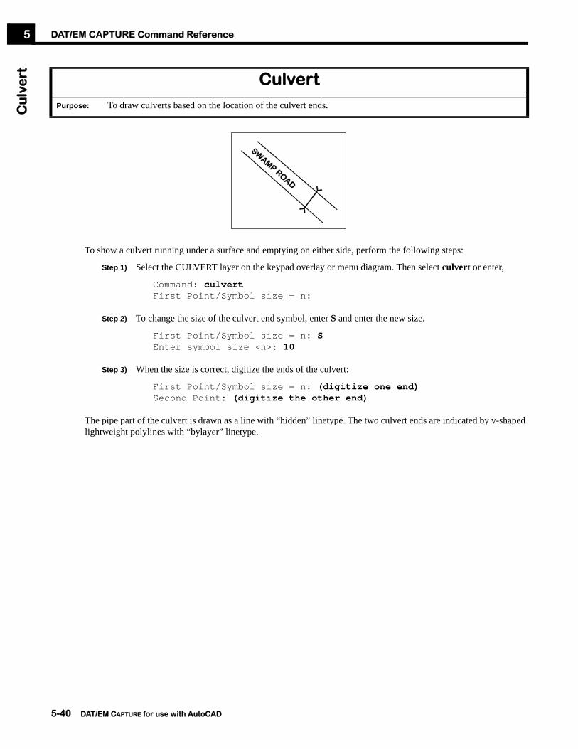
DAT/EM CAPTURE Command ReferenceC
ulv
ert
5
To show a culvert running under a surface and emptying on either side, perform the following steps:
Step 1) Select the CULVERT layer on the keypad overlay or menu diagram. Then select culvert or enter,
Command: culvertFirst Point/Symbol size = n:
Step 2) To change the size of the culvert end symbol, enter S and enter the new size.
First Point/Symbol size = n: SEnter symbol size <n>: 10
Step 3) When the size is correct, digitize the ends of the culvert:
First Point/Symbol size = n: (digitize one end)Second Point: (digitize the other end)
The pipe part of the culvert is drawn as a line with “hidden” linetype. The two culvert ends are indicated by v-shaped lightweight polylines with “bylayer” linetype.
CulvertPurpose: To draw culverts based on the location of the culvert ends.
5-40 DAT/EM CAPTURE for use with AutoCAD

DAT/EM CAPTURE Command ReferenceC
urb
5
Curb activates a settings dialog box, then draws the curb lines. Curblast draws the curb lines using the most recent curb or curbfilename settings, but does not activate the dialog box. Curbfilename <filename with path.reg> draws curb offsets using the settings stored in a file. The settings file for curbfilename may be created using the Save button on the curb dialog, and it may be stored anywhere on the local computer or its network.
To draw a curb along a street edge, perform the following steps:
Step 1) Digitize a polyline along either the road center line or along the top of the curb.
Step 2) To activate the settings box and draw the curb, use the curb command:
Command: curbSelect a polyline <Last>:
Or, to draw the curb using the settings from the most recent run of curb or curbfilename, use the curblast command:
Command: curblastSelect a polyline <Last>:
CurbCurbLast, CurbFilename <filename with path.reg>
Purpose: To add the curb and gutter offsets to a single polyline representing a street edge or center line. Curb activates a settings dialog and runs the command; curblast runs the command using the most recent settings; curbfilename <filename with path.reg> runs the command using the settings from a file.
(Curb backs and tops are shown offset in X,Y for demonstration purposes. Offset elevations vary.)
Draw either the center line ...
... or draw the curb top.
5-41 DAT/EM CAPTURE for use with AutoCAD

DAT/EM CAPTURE Command ReferenceC
urb
5
Or, to draw the curb using the settings stored in a file, use the curbfilename command:
Command: curbfilename c:\MyConfigFiles\CurbConfig42.regSelect a polyline <Last>:
Step 3) Select a polyline or accept L to use the most recently drawn object. A dialog box appears.
Step 4) Set the selected polyline to be either the center line of the road or the top of the curb. If Centerline is selected, select curbs/gutters to appear on the right, left, or on both sides of the selected polyline.
Step 5) Check on all desired offset components, Curb Top, Curb Bottom, Curb Back, Gutter. The Curb Top section will not be available if the selected polyline is already set as the curb top. If an offset is not checked, it will not be drawn.
• Set the selected polyline to be either the Center Line of the road or the Curb Top.
• If Center Line is selected, set the curbs and gutters to appear on the right, left, or on both sides of the selected polyline.
Check on all desired curb and gutter line offsets.
5-42 DAT/EM CAPTURE for use with AutoCAD

DAT/EM CAPTURE Command ReferenceC
urb
5
Step 6) Set the layer for each offset. To make a new layer, select the New... button and type in a new name. Accept the layer with the OK button. The new layer is created in AutoCAD immediately and the main dialog box returns. Note that even if the main dialog box is canceled, any new layers that were made still exist.
Step 7) Make X,Y, and Z offset settings for the components of the curb. If the curbs are made according to standard sizes, then the offsets may be entered using the keyboard. To measure the distances with the stereoplotter, check on the Measure box.
Step 8) To save the current settings, select the Save button. Both the curbfilename command and the Load button can use the resulting .reg file. To return all settings to the defaults, select the Reset button.
Step 9) When all settings are made, select OK. If necessary, prompts will appear to digitize offset distances. Then the offsets are drawn and the command ends.
See also: 3doffset, 3doffsetmeasure, Road
To create a new layer, select the New button.
Enter a new layer name, then select OK.
Choose whether to measure the distance, and whether to measure it immediately or after the dialog box has been accepted:• To measure a distance and return to the dialog box before placing
the offsets, check on a Measure box. Then select the Measure button. Follow the prompt to measure the distance. The dialog box returns with the new distance showing.
• To measure the distances and place the offsets without returning to the dialog box, check on the desired Measure boxes and make all other settings. Select the OK button. Follow the prompts to measure the distances. The curb offsets are drawn and the command is complete.
5-43 DAT/EM CAPTURE for use with AutoCAD

DAT/EM CAPTURE Command ReferenceD
atC
lip5
The clipit<version>.arx application must be loaded in AutoCAD in order for the datclip command to work. To run the datclip command, perform the following steps:
Step 1) Start the datclip command:
Command: datclip
Step 2) Make settings in the dialog box:
Step 3) When the settings are complete, select the Clip button. The status bar shows clipping progress.
Step 4) When the clipping is complete, either select new clip settings, or select Close to end the command.
DatClip(formerly called Clipit)
Purpose: To clip (delete) objects inside or outside of polylines. Clipping may be specified either by object or by layer.
exterior mode
interior mode
Hint: Use datclip to process a combination of object types and to perform interior and/or exterior clipping. To process interior clipping of point objects only, use ClipPoints instead. Although datclip can process interior clipping of points successfully, ClipPoints can do it faster. See “ClipPoints” on page 5-35 below.
There are two methods to specify the Clip Region areas:• To select individual polylines on any layer, select Objects,
then click on the Begin selecting button. Select every polyline to be used as a clipping edge, then press the <Enter> key when finished.
• To select all objects on certain layers, select Layers, then use the desired methods for building the list of layer names:
a.) Select the layer from the pop-down list, then click the “+” Add layer to list icon.
b.) Click on the Begin selecting button. Select a polyline from each layer to be used as a clipping edge, then press the <Enter> key when finished. The layer names are taken from the polylines and added to the list.
c.) To remove one item from the list, click on its line and press the “X” Delete selected button. To clear the entire list, press the “Eraser” Clear list button.
To select the Target areas, follow the directions for the Clip Region areas, but select objects or layers to be clipped.
Choose whether to clip inside or outside the clipping regions:•Select Interior to clip the target objects away from the inside of the clip regions.•Select Exterior to clip the target objects away from the outside of the clip regions.
5-44 DAT/EM CAPTURE for use with AutoCAD

DAT/EM CAPTURE Command ReferenceD
ate
mro
tate
5
The datemrotate command activates AutoCAD's dview twist command, and rotates the view to match the stereoplotter model. It is especially helpful when North on the stereo model is not aligned along the stereoplotter's y direction.
For example, if north is to the right on the photos, then when the stereoplotter moves to the right, the cursor on the screen moves up. This is very distracting to the user. datemrotate is used so the direction of the cursor movement is the same as the stereoplotter movement.
Pick datemrotate on the keypad or user menu, or type in the datemrotate command:
Command: datemrotatePick a point: (digitize a point with the stereoplotter)Move straight up on the stereoplotter and pick a point.(in the direction of Y axis): (move up and digitize again)
Almost any point may be picked. Just make sure there is room to move up in the stereoplotter's Y direction to take the second point:
Move straight up in Y on the stereoplotter and digitize a point.
DatemrotatePurpose: To rotate the screen view without changing the coordinates of the drawing. It is often used to make north
appear straight up on the screen.
5-45 DAT/EM CAPTURE for use with AutoCAD

DAT/EM CAPTURE Command ReferenceD
ate
msn
ap
5
The datemsnap command drives the stereoplotter to the (X,Y,Z) location of a snapped-to point. The stereoplotter must have computer-directed move capabilities. Digital stereoplotters and most analytical stereoplotters will be able to use this command.
To use datemsnap, perform the following steps:
Step 1) If desired, use the AutoCAD osnap command to set snaps on. Note that ‘osnap is a transparent command, and its snaps may be turned on or off during the digitizing process.
Step 2) Turn on datemsnap:
Command: datemsnap<On,Off>: onDatemSnap is now ON.
Step 3) Start the desired 3D command. Datemsnap checks if certain 3D commands are active, and does not affect other commands.
Step 4) When the snap is desired, either use an active ‘osnap snap or enter an AutoCAD snapping command such as endp or nea. When the snapping point is digitized, the stereoplotter will be driven to the (X,Y,Z) of the snapping location.
Step 5) When finished using 3D snaps, turn off the snapping command:
Command: datemsnap<On,Off>: offDatemSnap is off
DatemsnapPurpose: (Analytical or digital stereoplotters with move capabilities only) Drive the stereoplotter to the (X,Y,Z) of a
snapped-to point while 3dpoly or Autoarc3d is active.
Commands that work with datemsnap
3dpoly (AutoCAD command)
Autoarc3d (page 5-17)
5-46 DAT/EM CAPTURE for use with AutoCAD

DAT/EM CAPTURE Command ReferenceD
atm
ove
5
The datmove command allows the user to direct the analytical or digital stereoplotter to move to a specified coordinate. The stereoplotter must have computer-directed move capabilities.
To activate the datmove dialog box, choose the keypad or menu item, or enter,
Command: datmove
Select either a control point or a user-entered point, select the coordinate, then use the Move button.
DatmovePurpose: (Analytical or digital stereoplotters with move capabilities only) Move the analytical or digital
stereoplotter to a control point or user-specified coordinate.
See also: Contourdown, Contourup, Movebypick, Zmove
Choose Control to select a control point from the control file. Choose User to enter a coordinate
Enter a coordinate if User is on.
Select a coordinate if Control is on.
Select Move to move the stereoplotter.
5-47 DAT/EM CAPTURE for use with AutoCAD

DAT/EM CAPTURE Command ReferenceD
atp
an
5
It is often convenient to perform a transparent view pan. A transparent pan will not cancel or interfere with any other active command. The datpan command activates a transparent zoom center command whenever the stereoplotter’s cursor approaches the edge of the video screen.
To activate datpan, select the keypad or menu key or enter the command,
Command: datpan<Off>/On/Percent:
The options are as follows:
The datpan Percent option is illustrated in the following diagram:
DatpanPurpose: To perform a transparent view zoom whenever the stereoplotter’s cursor approaches the edge of the AutoCAD
graphics view.
Off Turn off view panning. The cursor will be able to move out of the view.
On Turn on view panning. The cursor will never move out of the view; when it approaches the edge of the view, a Zoom Center will be performed.
P Control the location of the cursor when the Zoom Center takes place. This value may be set between 0% and 100%.
• 100% would cause a Zoom Center whenever the cursor moved at all; the cursor would appear to remain in the center of the view at all times.
• 50% would cause a Zoom Center when the cursor moved half the distance from the center to the edge of the view.
• 10% would cause a Zoom Center when the cursor moved nine-tenths the distance from the center to the edge of the view.
Datpan View PercentagesIf Percent is set to 10%, the view pans when the cursor attempts to move outside this rectangle
If Percent is set to 40%, the view pans when the cursor attempts to move outside this rectangle
5-48 DAT/EM CAPTURE for use with AutoCAD

DAT/EM CAPTURE Command ReferenceD
ep
5
Before starting any block patterning command, perform the following:
• Set the layer for the new blocks.
• Use the setup command to verify the Block scale factor and Block rotation angle and select the desired Planimetric Patterning setting.
To insert ticks on depression contours, select the keypad or menu item or enter the dep command:
Command: depSelect objects <Last>:
Choose one or more depression contours (polylines) or enter L to select the most recently digitized object. The computer then prompts:
(T)oggle side/(B)lock scale=#/(P)attern dist=# <Enter>:
The blocks appear visually along the polyline, but are not permanent objects until <Enter> is pressed. Several options may be changed before the blocks are actually inserted:
• To instantly change the direction of the blocks, enter T.
• To change the block size, enter B and set a new scale.
• To change the block pattern spacing, enter P and set the new spacing in ground units.
• When the blocks are correct, press <Enter> to accept them.
The file is searched for the block DTICKR or DTICKL. If the block does not already exist, it is created. The ticks are then inserted at intervals along the depression contour.
DepPurpose: To insert depression tick block symbols along a depression contour.
All blocks inserted at the same elevation!If on (checked), all the blocks will be inserted as follows:•For 2D polylines: at the polyline’s Z•For 3D polylines: at Z=0 and evenly spaced in the (X,Y) plane.
Blocks inserted at the polyline elevation.If off (not checked), the blocks will be inserted at the polyline Z. On 3D polylines, the elevation will be interpolated along the polyline segment.
(from the setup box)
5-49 DAT/EM CAPTURE for use with AutoCAD

DAT/EM CAPTURE Command ReferenceD
ep
ress
ion
5
To automatically find existing depression contours and either pattern them with blocks or change their layer, perform the following steps:
Step 1) Prepare the drawing file. The file should have existing elevation contours:
• All contours, depression and rising, may be on the same layer. (If depression contours are already on a different layer, “Dep” on page 5-49 above may be a better choice.)
• The depression contours must be closed polylines.
• All contours must be accurate in 3D. That is, they should be 2D or 3D polylines with Z equal to the ground elevation.
• The drawing should contain depression indicators, which may be blocks, points, or 3D polylines (breaklines) at the lowest elevations. There should be at least one depression indicator inside the area of each depression contour.
Step 2) Load the ...Program Files\AutoCAD (version)\Datem\Depression(version).arx file. To load the file, use the appload command or select Load Application from AutoCAD’s Tools pull-down menu.
DepressionPurpose: To automatically find existing depression contours and either pattern them with blocks or change their layer.
Spot elevation block depression indicator
Breakline 3D polyline depression indicator
DTM points depression indicators
5-50 DAT/EM CAPTURE for use with AutoCAD

DAT/EM CAPTURE Command ReferenceD
ep
ress
ion
5
Step 3) Start the depression command and start to make settings in the dialog box:
Command: depression
Step 4) Continue to make settings:
Step 5) Select Apply to run the command.
Check one or more layers that contain elevation contours.
Choose what to do when a depression contour is found:• Pattern places blocks at
intervals along the polyline. Choose the block name, layer, scale, and distance apart.
• Change Layer changes the polyline to a different layer.
Choose one or more types of depression indicators that exist in the file:• Block Name: These blocks exist at the
lowest ground elevations. These are usually spot elevations.
• Point Layer: Points exist at the lowest ground elevations. These are usually DTM mass points.
• BreakLineLayer: 3D polylines exist at the lowest ground elevations in the file. These are usually breaklines that were digitized along the highest and lowest ground features, for example, along ridge tops and ditch bottoms.
5-51 DAT/EM CAPTURE for use with AutoCAD

DAT/EM CAPTURE Command ReferenceD
TM
dis
trib
uto
r5
The DTMdistributor command is used to combine overlapping sets of DTM points into one non-overlapping set at a new grid interval.
To use DTMdistributor, perform the following steps:
Step 1) Prepare one or more DTM point sets. Point sets may be XYZ data contained in one or both of the following formats:
a.) Point objects currently in the AutoCAD drawing;
b.) Inpho MATCH-T files.
Step 2) Start the DTMdistributor command:
Command: dtmdistributor
DTMdistributorPurpose: To combine two or more DTM point sets into a single set; to redistribute DTM points at a new grid interval.
Distribute DTMs
Input from layers and/or files Output into layers and/or files
Distributed into a single set at a new grid interval
Three separate sets of DTM XYZ data
5-52 DAT/EM CAPTURE for use with AutoCAD

DAT/EM CAPTURE Command ReferenceD
TM
dis
trib
uto
r5
Step 3) Points in the current drawing file may be used as input. To use points, select the Drawing Input tab and select layers that contain points. Note that Drawing Input and Match Files input can be used at the same time.
Step 4) If Inpho MATCH-T output files are available, select the Match Files tab. Use the Browse for Match Files button to select each MATCH-T xyz, yxz, dtm, and/or dem file. Note that Drawing Input and Match Files input can be used at the same time.
To use points on layers in the current drawing as input, select the Drawing Input tab.
Any listed layer may be removed, if desired:• To remove all the files from the list, select
the eraser icon.• To remove one file, highlight its name in
the list, then select the “X” icon.
To select points in the file for layer matching, select the Select entities... button. Select points, then click the right mouse button or key in <Enter> to return to this dialog box.
To select a layer from the current drawing file, select the layer name from the pop-down list, then click the “+” icon.
If one or more MATCH-T output files are available as input, select the Match Files tab.
Check on the types of MATCH-T points to use as input. If a point is found in the file, but its type code is not checked on, then the point will be ignored.
Select the Browse for Match Files button and select one or more MATCH-T output files.
Any listed file may be removed, if desired:• To remove all the files from
the list, select the eraser icon.• To remove one file, highlight
its name in the list, then select the “X” icon.
5-53 DAT/EM CAPTURE for use with AutoCAD

DAT/EM CAPTURE Command ReferenceD
TM
dis
trib
uto
r5
Step 5) Select the Output tab to set one or more output formats:
Step 6) If desired, select each tab again to verify that all necessary settings are correct.
Step 7) Select the Distribute button to create the new DTM point distribution and output formats.
Select the Output tab.
Select one or more of the following output formats for the newly calculated DTM grid:• To place points in the current drawing file,
select a Layer for the new points. To create a new layer, select the Launch... button to the right of the layer field.
• To write the points out to an ASCII (text) file, specify a file name in the XYZ ASCII File field.
• To write the points out to a Summit binary format DTM file for use with SUMMIT EVOLUTION’s Terrain Following tool, specify a file name in the Summit DTM File field.
Note: To prevent an output format from being used, leave its field blank.
Set Distance to the distance between points in the new DTM grid.
Drag the angle pointer to set the Angle of the rows in the new DTM grid.
5-54 DAT/EM CAPTURE for use with AutoCAD

DAT/EM CAPTURE Command ReferenceD
TM
ed
ito
r5
The DTMeditor command edits points that are in the currently open AutoCAD file.
To use DTMeditor, perform the following steps:
Step 1) Start the DTMeditor command:
Command: dtmeditor
Step 2) Begin to make settings in the DTM Editor dialog box:
DTMeditorPurpose: To edit XYZ point data in the AutoCAD file.
To process only those points/blocks that are inside polygons (closed polylines), select a Within Polygons layer.• If necessary, select the Delete all boundary
polygons to delete existing polygons on the Within Polygons layer.
• To draw new polygons around the points/blocks, select the Add boundary polygons button and digitize one or more polygons. When finished, click the right mouse button or key in <Enter> to return to the dialog box.
• To save any newly drawn polygons after DTMeditor is finished, check on Save Polygons.
Select one or more layers search for the points and/or blocks. If desired, use the check mark buttons to check on or off all the layers at once.
Select the type of object to edit:• Check on Points to search for points
on the On Layers layers.• Check on Blocks to search for blocks
inserted on the On Layers layers.
5-55 DAT/EM CAPTURE for use with AutoCAD

DAT/EM CAPTURE Command ReferenceD
TM
ed
ito
r5
Step 3) Continue to make settings and choose an editing operation in the DTM Editor dialog box:
Step 4) After Measure, Set, or Shift is finished, a message appears to show how many objects were edited. The DTM Editor box reappears.
Step 5) Continue editing objects. Select Close when finished.
Choose an operation to edit the points/blocks:• Redigitize each coordinate: If connected with DAT/EM
CAPTURE to a computer-controlled stereoplotter (not an analog stereoplotter), Measure Each drives the stereoplotter cursor to each point or block and allows the user to redigitize its position.
• Move to a specific coordinate: Enter a new coordinate in the X, Y, and Z fields. Select Set to move the points/blocks to this exact coordinate. Note that only those components that are checked on will be moved, even if a value is entered in the component field.
• Shift by constant values: Enter a new coordinate in the X, Y, and Z fields for those components that are checked. Select Set to move the points/blocks to this exact coordinate. Note that only those components that are checked on will be shifted, even if a value is entered in the component field.
Note: The point/block moves may not be visible until the DTM Editor dialog box is closed.
Choose the coordinate components, X, Y, and/or Z, that are to be changed on each block/point. If a coordinate component is not checked, that component on the point/block will not change.
5-56 DAT/EM CAPTURE for use with AutoCAD
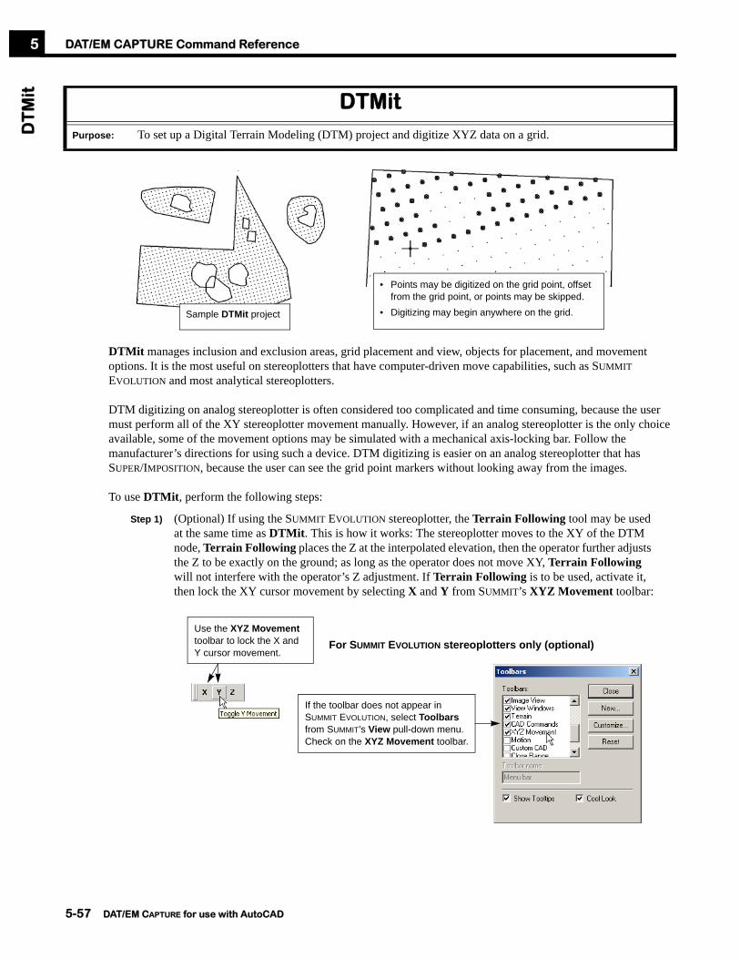
DAT/EM CAPTURE Command ReferenceD
TM
it5
DTMit manages inclusion and exclusion areas, grid placement and view, objects for placement, and movement options. It is the most useful on stereoplotters that have computer-driven move capabilities, such as SUMMIT EVOLUTION and most analytical stereoplotters.
DTM digitizing on analog stereoplotter is often considered too complicated and time consuming, because the user must perform all of the XY stereoplotter movement manually. However, if an analog stereoplotter is the only choice available, some of the movement options may be simulated with a mechanical axis-locking bar. Follow the manufacturer’s directions for using such a device. DTM digitizing is easier on an analog stereoplotter that has SUPER/IMPOSITION, because the user can see the grid point markers without looking away from the images.
To use DTMit, perform the following steps:
Step 1) (Optional) If using the SUMMIT EVOLUTION stereoplotter, the Terrain Following tool may be used at the same time as DTMit. This is how it works: The stereoplotter moves to the XY of the DTM node, Terrain Following places the Z at the interpolated elevation, then the operator further adjusts the Z to be exactly on the ground; as long as the operator does not move XY, Terrain Following will not interfere with the operator’s Z adjustment. If Terrain Following is to be used, activate it, then lock the XY cursor movement by selecting X and Y from SUMMIT’s XYZ Movement toolbar:
DTMitPurpose: To set up a Digital Terrain Modeling (DTM) project and digitize XYZ data on a grid.
• Points may be digitized on the grid point, offset from the grid point, or points may be skipped.
• Digitizing may begin anywhere on the grid.Sample DTMit project
If the toolbar does not appear in SUMMIT EVOLUTION, select Toolbars from SUMMIT’s View pull-down menu. Check on the XYZ Movement toolbar.
Use the XYZ Movement toolbar to lock the X and Y cursor movement.
For SUMMIT EVOLUTION stereoplotters only (optional)
5-57 DAT/EM CAPTURE for use with AutoCAD

DAT/EM CAPTURE Command ReferenceD
TM
it5
Step 2) Digitize new inclusion and exclusion areas or verify that they already exist:
a.) Although 2D polylines will work, it is recommended to draw all inclusion and exclusion boundaries using 3D polylines at the ground elevation. The 3D polylines are especially important if using SUPER/IMPOSITION, so that the boundaries and grid markers are visible at ground elevation.
b.) The grid marker elevations are calculated based on the elevation of the inclusion and exclusion boundaries. Be aware that most stereoplotters will drive to the XYZ of the first grid marker, so do not draw the boundaries at Z=0 unless the project is near sea level!
c.) Inclusion and exclusion boundaries may be drawn either clockwise or counterclockwise.
d.) Inclusion and exclusion boundaries may either be placed on separate layers or selected individually. It is the user’s choice whether to use separate layers, or even many different layers, for inclusion and exclusion areas polylines.
Step 3) Start the DTMit command:
Command: dtmit
Sample inclusion and exclusion areas
5-58 DAT/EM CAPTURE for use with AutoCAD
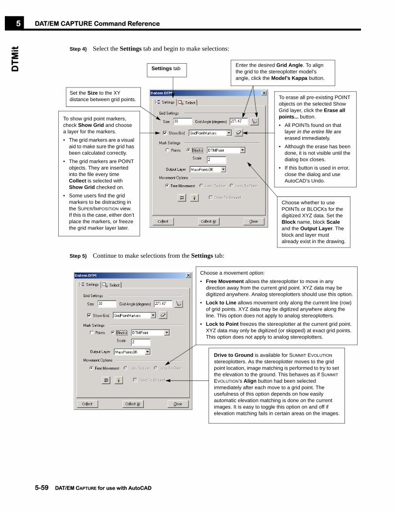
DAT/EM CAPTURE Command ReferenceD
TM
it5
Step 4) Select the Settings tab and begin to make selections:
Step 5) Continue to make selections from the Settings tab:
Settings tab Enter the desired Grid Angle. To align the grid to the stereoplotter model’s angle, click the Model’s Kappa button.
Set the Size to the XY distance between grid points.
To show grid point markers, check Show Grid and choose a layer for the markers.• The grid markers are a visual
aid to make sure the grid has been calculated correctly.
• The grid markers are POINT objects. They are inserted into the file every time Collect is selected with Show Grid checked on.
• Some users find the grid markers to be distracting in the SUPER/IMPOSITION view. If this is the case, either don’t place the markers, or freeze the grid marker layer later.
To erase all pre-existing POINT objects on the selected Show Grid layer, click the Erase all points... button.• All POINTs found on that
layer in the entire file are erased immediately.
• Although the erase has been done, it is not visible until the dialog box closes.
• If this button is used in error, close the dialog and use AutoCAD’s Undo.
Choose whether to use POINTs or BLOCKs for the digitized XYZ data. Set the Block name, block Scale and the Output Layer. The block and layer must already exist in the drawing.
Choose a movement option:• Free Movement allows the stereoplotter to move in any
direction away from the current grid point. XYZ data may be digitized anywhere. Analog stereoplotters should use this option.
• Lock to Line allows movement only along the current line (row) of grid points. XYZ data may be digitized anywhere along the line. This option does not apply to analog stereoplotters.
• Lock to Point freezes the stereoplotter at the current grid point. XYZ data may only be digitized (or skipped) at exact grid points. This option does not apply to analog stereoplotters.
Drive to Ground is available for SUMMIT EVOLUTION stereoplotters. As the stereoplotter moves to the grid point location, image matching is performed to try to set the elevation to the ground. This behaves as if SUMMIT EVOLUTION’s Align button had been selected immediately after each move to a grid point. The usefulness of this option depends on how easily automatic elevation matching is done on the current images. It is easy to toggle this option on and off if elevation matching fails in certain areas on the images.
5-59 DAT/EM CAPTURE for use with AutoCAD

DAT/EM CAPTURE Command ReferenceD
TM
it5
Step 6) Continue to make selections from the Settings tab:
Step 7) Now choose the Select tab and select the inclusion and exclusion polylines or layers:
Choose a grid row movement setting:
• indicates that it is already set to move left to right along one grid row, then right to left along the next grid row.
• indicates that it is already set to move in the same direction along every grid row.
For systems with Super/Imposition, choose a setting for Indicate the DTM position in SI:• If the icon is light gray (on), then a temporary superimposed
point marker appears to mark the current grid XY position. The Z of this point is set to the Z of the most recently digitized point. Read more about managing the SUPER/IMPOSITION display of DTM points below in Step 12.
• If the icon is dark gray (off), then no additional point marker is displayed at the current grid point position.
Select tabThere are two methods to specify the Include areas. They are both used at the same time during grid calculations:• To select individual polylines on any layer, select Objects
and then click on the Begin selecting objects/layers button. Select every polyline to be used as an inclusion boundary, then press the <Enter> key to return to the dialog.
• To select all objects on certain layers, select Layers. Then there are two choices for obtaining the layer names:
a.) Select the layer from the pop-down list, then click the “+” icon.
b.) Click on the Begin selecting objects/layers button. Select a polyline from each layer to be used as an inclusion boundary, then press the <Enter> key when finished. The layer names are taken from the polylines and added to the list.
Note that all objects and layers are used during grid calculation, regardless of the radio button status. This allows you to select by layer and by object for the same run.
To select the Exclude areas, follow the directions for the Include areas, but select exclusion polylines or exclusion layers.
5-60 DAT/EM CAPTURE for use with AutoCAD

DAT/EM CAPTURE Command ReferenceD
TM
it5
Step 8) Now choose a grid collection start option:
Step 9) If Collect At was selected, a prompt appears:
Select the area to begin collecting {pick}
With either the mouse or the stereoplotter, select near the grid point or area where digitizing should begin. The stereoplotter drives to the grid point that is nearest to the selected point, and the data collection mode begins.
Step 10) If the grid point markers were checked on, the grid appears as points in the drawing. Verify that the grid has been calculated in the correct XY locations. Remember, the grid point markers are not at the ground Z. They are not data points, they are a tool for viewing the calculated grid.
Step 11) A prompt appears:
Measure point (Cancel to skip/Return to dialog/Toggle DTG(now off)/Undo):
Collect XYZ data. Choose from the following actions:
a.) Digitize a point: Carefully position the stereoplotter at the Z elevation of the ground. Or, if XY movement is possible, carefully position the stereoplotter at the desired XYZ coordinate. Press the stereoplotter’s “Pick” digitizing switch1.
b.) Skip a point: Press the stereoplotter’s “Cancel” switch to skip to the next grid point.
c.) Stop digitizing and return to the dialog: Enter R to stop digitizing and return to the dialog. Changes may then be made to the DTMit settings, or the DTMit dialog may be closed. To resume the same project later, use the same DTMit settings; previously digitized points will be found and skipped automatically.
d.) Toggle “DTG” (Drive to Ground): Enter T to toggle “Drive to Ground” on or off.
e.) Undo the last point: Enter U to remove the last point and move back to its location. The points can be undone back to the first point of this DTMit session. If part of the project was digitized with a previous run of DTMit, those previously existing points cannot be undone.
1. In DTM projects, the “Pick” and “Cancel” switches are used repeatedly. For the user’s comfort, the most easy-to-use switches should be programmed to these functions. See “Buttons” on page 5-27 for instructions.
Choose a grid collection start option:• Choose Collect to drive the stereoplotter to the
first point on the grid and begin XYZ data collection mode.
• Choose Collect At and to drive the stereoplotter to a selected starting point. To the “Select the area to begin collecting” prompt, digitize a point near the desired grid point. The stereoplotter drives to the grid point that is nearest to the selected point, and the data collection mode begins.
5-61 DAT/EM CAPTURE for use with AutoCAD

DAT/EM CAPTURE Command ReferenceD
TM
it5
Step 12) If SUPER/IMPOSITION is present, make sure the settings are convenient for the user. The following are hints and troubleshooting ideas for DTMit with SUPER/IMPOSITION:
a.) While the Show Grid markers are convenient for checking the grid calculation, they may be distracting during digitizing. Use the transparent ‘layer command to freeze the grid marker layer without interrupting DTMit.
b.) If using SUMMIT EVOLUTION, try different SUPER/IMPOSITION Clip Scope settings. Some users may like the way Clip Scope makes the marker disappear when the cursor is very close to it.
c.) If grid markers do not appear on the SUPER/IMPOSITION display, check that SI is turned ON in AutoCAD and that POINT display is on in the SUPER/IMPOSITION client or in SUMMIT EVOLUTION’s SI settings. SUMMIT EVOLUTION users should check the Clip Scope setting.
d.) If two different grid markers appear at the current grid location, it is because Show grid and Indicate the grid location in SI are both on. They appear at different elevations because the Show grid point is based on the inclusion/exclusion area elevations, and the Indicate... point is based on the elevation of the last digitized point. To reduce the number of points displayed in SUPER/IMPOSITION, simply freeze the Show grid layer using the transparent ‘layer command.
Sample of DTMit in progress
5-62 DAT/EM CAPTURE for use with AutoCAD

DAT/EM CAPTURE Command ReferenceE
db
ox
5
The edbox command is a tool to keep track of edited areas on a drawing. Edit boxes are useful to avoid gaps in the edited area, and they make it easier for two people to edit the same project.
Use edbox to place box-shaped blocks over a newly digitized drawing. Completely edit the area under a box, then erase the box. When the boxes are all gone, the project is completely edited.
First start the command and define the entire area of box coverage:
Command: edboxBox from point:Box to point:
Select opposite corners of the area to be covered. Then define the box block size:
Block size from point:Block size to point:
Select opposite corners defining the size of an individual box. The box size should be defined so all objects in the box can be edited without zooming smaller than the box.
EdboxPurpose: The edbox command is a tool to keep track of edited areas on a drawing.
5-63 DAT/EM CAPTURE for use with AutoCAD

DAT/EM CAPTURE Command ReferenceE
dit
line
5
To run the editline command, perform the following steps:
Step 1) Start the editline command:
Command: editline[End/Inner/Join/ShiftZ]:
EditlinePurpose: To edit polylines. Choose from the following functions:
1. End: Append to an end or replace an end section with a new series of straight segments and/or arcs;
2. Inner: Replace an interior section with a new series of straight segments and/or arcs;
3. Join: Join two polylines (or selected portions of two polylines) by drawing a new series of straight segments and/or arcs between them;
4. ShiftZ: Edit the elevation of individual vertices within a 3D polyline; edit the elevation of a 2D polyline.
Editline End
Editline Inner
Editline Join
Editline ShiftZ
Note: For a 2D polyline, the entire line is changed to the new elevation.
Original polyline
Select end of polyline and draw new section.
Finish.
Select section to replace and draw new section Finish.Original
polyline
Two original polylines
Select ends of polylines and draw new section Finish.
Z=11.24
Z=11.25
Z=5998.00
Z=-999.99Z=11.28
Set the correct elevation and select the vertex. Repeat.
Z=11.24
Z=11.25
Z=11.26
Z=11.27Z=11.28
5-64 DAT/EM CAPTURE for use with AutoCAD

DAT/EM CAPTURE Command ReferenceE
dit
line
5
Step 2) Select an editing mode and follow the prompts:
a.) End: To replace an end section of a polyline with a new section, enter E, e, or end.
Select polyline break point:
Select the point on the polyline where the new section is to connect. The closest end section is removed and a drawing prompt appears. Go on to the next step for information about drawing the new section.
b.) Inner: To replace an interior section of one polyline with a new section, enter I, i, or inner.
Select first break point: Select second break point:
Select the ends of the polyline section that is to be replaced. The section that will be removed is highlighted in red and a digitizing prompt appears. Go on to the next step for information about drawing the new section.
c.) Join: To replace the end sections of two polylines, draw a new section, and join all three parts together into one polyline, enter J, j, or join.
Select first polyline break point:Select second polyline break point:
Select the points on the first and second polylines where the new section is to connect. The polylines may be 2D or 3D. Note that if one polyline is 3D, the result is 3D. If both polylines are 2D, the result is 2D.
Now choose the correct ends to remove. The first polyline turns green on the end that is to be saved and red on the end that is to be removed. A prompt appears:
Accept/Opposite breakpoints? <A>
If the red end is the correct end to remove, select A or <Enter>. To remove the green end instead, enter O, o, or Opposite; the red highlight changes to indicate the other end of the polyline. Repeat for the second polyline.
The red highlights remain on the screen to show the end sections that are to be removed. A digitizing prompt appears. Go on to the next step for information about drawing the new section.
d.) ShiftZ: To edit the elevation of individual vertices, enter S, s, or shiftz.
Please measure vertex(3d) or line(2d)at its new elevation:
If using the stereoplotter to digitize, set the stereoplotter to the correct elevation, then pick a 3D polyline’s vertex or a 2D polyline entity with the stereoplotter’s digitizing switch. If using the system mouse to digitize, first use AutoCAD’s elev command to set the correct elevation, then use editline ShiftZ and pick with the mouse. Repeat as necessary for other vertices. Enter <Esc> to exit the ShiftZ prompt and return to the other editline options.
5-65 DAT/EM CAPTURE for use with AutoCAD

DAT/EM CAPTURE Command ReferenceE
dit
line
5
Step 3) Digitize the new section. The digitizing prompt is different depending on whether the original polyline is 2D or 3D. The combined 2D and 3D choices are as follows:
Step 4) Input <Enter> to finish the new section and end the editline command.
Action Editline Result
• Digitize a point Digitize a segment endpoint or an arc point, depending on which digitizing mode is active.
• Enter an AutoCAD snapping command such as ENDP
Snap to another object and continue.
• <Enter> or spacebar Finish the new polyline section and complete editline.
• 3 For 2D polylines only. Change from straight segment digitizing mode to 3-point arc mode. Digitize a point along the arc, then digitize the end point of the arc.
• A Change from straight segment digitizing mode to arc mode.
• For a 3D polyline: Start a 3-point simulated arc. Digitize a point along the arc and digitize the arc’s end point. Because true 3D arcs are not possible in AutoCAD, many straight line segment strokes are added to simulate an arc shape. These vertices vary gradually in elevation from the elevation of the first point to the middle point, and then again from the middle point to the end point.
• For a 2D polyline: Start a 2-point arc. Digitize the end point of the arc.
• C Close the polyline and finish the editline command.
• L Change from arc mode to straight segment digitizing mode. Digitize a segment endpoint.
• P Use this option only when DAT/EM CAPTURE is running and the stereoplotter is used as the digitizer. Toggle the elevation setting to be used when snapping to other objects:
• To snap to the X,Y location of the other object, but use the stereoplotter’s elevation, turn [on] the stereoplotter Z setting.
• To snap to the X,Y, and Z location of the other object, turn [off] the stereoplotter Z setting.
• R Change the last two straight segments (three vertices) to a three-point arc. This is a simulated arc for 3D polylines.
• S Enter a new number of circle segments (strokes) for simulating 3D arcs. A higher number produces more segments.
• U Remove the last vertex and continue.
5-66 DAT/EM CAPTURE for use with AutoCAD

DAT/EM CAPTURE Command ReferenceFe
nc
e5
Before starting any block patterning command, perform the following:
• Set the layer for the new blocks.
• Use the setup command to verify the Block scale factor and Block rotation angle and select the desired Planimetric Patterning setting.
Select the Fence keypad or menu item or type fence at the command prompt:
Command: fenceSelect objects <Last>:
Choose one or more polylines or enter L to select the most recently digitized object. The computer then prompts:
B)lock scale=#/(P)attern dist=# <Enter>:
The blocks appear visually along the polyline, but are not permanent objects until <Enter> is pressed. Several options may be changed before the blocks are actually inserted:
• To change the block size, enter B and set a new scale.
• To change the block pattern spacing, enter P and set the new spacing in ground units.
• When the blocks are correct, press <Enter> to accept them.
The file is searched for the block called FENCETICK. If this block does not already exist, it is created. Then the block is inserted at intervals along each selected polyline.
FencePurpose: To insert fence tick block symbols along digitized fence polylines.
All blocks inserted at the same elevation!If on (checked), all the blocks will be inserted as follows:•For 2D polylines: at the polyline’s Z•For 3D polylines: at Z=0 and evenly spaced in the (X,Y) plane.
Blocks inserted at the polyline elevation.If off (not checked), the blocks will be inserted at the polyline Z. On 3D polylines, the elevation will be interpolated along the polyline segment.
(from the setup box)
5-67 DAT/EM CAPTURE for use with AutoCAD

DAT/EM CAPTURE Command ReferenceG
rail
5
Before starting any block patterning command, perform the following:
• Set the layer for the new blocks.
• Use the setup command to verify the Block scale factor and Block rotation angle and select the desired Planimetric Patterning setting.
Select the Guard Rail keypad or menu item, or type grail. The computer prompts:
Command: grailSelect objects <Last>:
Choose one or more polylines or enter L to select the most recently digitized object. The computer then prompts:
(T)oggle side/(B)lock scale=#/(P)attern dist=# <Enter>:
The blocks appear visually along the polyline, but are not permanent objects until <Enter> is pressed. Several options may be changed before the blocks are actually inserted:
• To instantly change the direction of the blocks, enter T.
• To change the block size, enter B and set a new scale.
• To change the block pattern spacing, enter P and set the new spacing in ground units.
• When the blocks are correct, press <Enter> to accept them.
The file is searched for the block GTICKR or GTICKL. If the block does not already exist, it is created. The block is then inserted at intervals along the guard rail polyline.
GrailPurpose: To insert guard rail block symbols along a digitized guard rail polyline.
All blocks inserted at the same elevation!If on (checked), all the blocks will be inserted as follows:•For 2D polylines: at the polyline’s Z•For 3D polylines: at Z=0 and evenly spaced in the (X,Y) plane.
Blocks inserted at the polyline elevation.If off (not checked), the blocks will be inserted at the polyline Z. On 3D polylines, the elevation will be interpolated along the polyline segment.
(from the setup box)
5-68 DAT/EM CAPTURE for use with AutoCAD

DAT/EM CAPTURE Command ReferenceG
rid
it5
The gridit command is often used at the edit stage to insert the map sheet grid with northing and easting grid text. It may also be used for a variety of other grid types, including a Digital Terrain Modeling-type grid.
To place a labeled grid, perform the following steps:
Step 1) Draw a closed polyline around the area to be gridded.
Step 2) Start the gridit command.
Command: griditSelect a polyline <Last>:
Step 3) Select the closed boundary polyline.
Step 4) Make settings in the DAT/EM Gridit dialog box:
Step 5) Select OK to create the grid.
GriditPurpose: To place objects (such as ticks, polylines, or blocks) on a grid. Options are given for grid labels and formats.
• Save saves the current settings.• Load restores the settings saved
by the most recent Save button hit. Select Reset to restore the DAT/EM CAPTURE defaults.
Select OK to create the grid.
5-69 DAT/EM CAPTURE for use with AutoCAD

DAT/EM CAPTURE Command ReferenceG
rid
it5
Gridit Example 1
5-70 DAT/EM CAPTURE for use with AutoCAD

DAT/EM CAPTURE Command ReferenceG
rid
it5
Gridit Example 2
5-71 DAT/EM CAPTURE for use with AutoCAD

DAT/EM CAPTURE Command ReferenceIn
s5
Ins is a function that offers quick and repeated block or point insertion. This command is often called along with -inssetup from the .kds keypad overlay or menu diagram definition file in the symbol insertion section. For example, to insert a series of runway light blocks at a selected scale, a keypad key is programmed as follows:
-LAYER{RET}SET{RET}UTILITIES{RET}-INSSETUP{RET}S{RET}INS{RET}RLIGHT{RET}
To use the ins command, perform the following steps:
Step 1) Make settings using the inssetup or -inssetup command. See “Inssetup and -Inssetup” on page 5-73.
Step 2) If inserting a block that has block tag attributes in its definition, use the setup command to choose a setting for the Prompt for block tag information. If this setting is checked on, then ins prompts for block tags. See “Setup” on page 5-112.
Step 3) Start the ins command:
Command: ins
Step 4) To the “Block name” prompt, enter the block name if necessary. The block name will appear automatically if it was set with the inssetup dialog box. Note that this prompt does not appear if placing points.
Block name (NAME)/?: (enter the block name if necessary)
Step 5) To the “Undo/Pick point” prompt, digitize the insertion location for the block or point.
Undo/Pick point: (digitize the insertion location)
Step 6) If the “Scale”, “Rotate”, or “Scale and Rotate” prompt appears, digitize a second point to define the scale and/or rotation angle for the block. Note that this prompt may not appear for some settings.
Scale and Rotate: (digitize the scale/rotation)
Step 7) Whenever necessary, enter U to undo (remove) the last inserted block or point.
Step 8) If desired, repeat steps 5, 6, and 7 to insert more blocks or points.
Note that the shot command is still available to insert blocks, but ins now has all the functionality of shot (see “Shot” on page 5-116.). Additionally, inssetup and ins can insert blocks on a specified non-current layer.
InsPurpose: To quickly and repeatedly insert blocks or points using the settings made by inssetup or -inssetup.
5-72 DAT/EM CAPTURE for use with AutoCAD

DAT/EM CAPTURE Command ReferenceIn
sse
tup
an
d -
Inss
etu
p5
This ins and inssetup/-inssetup commands work together to make block or point insertion settings, then quickly and repeatedly insert blocks or points. Inssetup activates a dialog box to make settings for the ins command. -Inssetup works on the command line and does not activate a dialog box. Inssetup offers one layer setting that -inssetup does not, but most of the settings for ins can be made interchangeably by either inssetup or -inssetup.
To use the -inssetup command to make command line settings for ins, perform the following steps:
Step 1) Start the -inssetup command:
Command: -inssetupOne/Rotate/Scale/(A)ll/Point:
Step 2) Enter the desired letter option to make settings for the ins command:
a.) Enter the letter O to insert a block each time the digitizing switch is pressed.
b.) Enter R to insert a block after pressing the digitizing switch twice. The first pick is the insertion point, and the second pick defines the block rotation angle.
c.) Enter S to insert a block after pressing the digitizing switch twice. The first pick is the insertion point, and the second pick defines the block scale factor.
d.) Enter A to insert a block after pressing the digitizing switch twice. The first pick is the insertion point, and the second pick defines both the rotation angle and the block scale factor.
e.) Enter P to insert an AutoCAD POINT each time the digitizing switch is pressed.
Step 3) Use the ins command to insert blocks or points at any time after -inssetup is finished. Note that any settings made later with the inssetup dialog box override settings made previously with -inssetup.
Because -inssetup does not activate a dialog box, the -inssetup and ins commands are often programmed together on the DATEM KEYPAD. For example, to insert a series of runway light blocks at a selected angle, a keypad key is programmed as follows:
-LAYER{RET}SET{RET}UTILITIES{RET}-INSSETUP{RET}R{RET}INS{RET}RLIGHT{RET}
Inssetup and -InssetupPurpose: To make settings for the ins command. Inssetup activates a dialog box, but -inssetup does not.
5-73 DAT/EM CAPTURE for use with AutoCAD

DAT/EM CAPTURE Command ReferenceIn
sse
tup
an
d -
Inss
etu
p5
To use the inssetup command to activate a dialog box to make settings for ins, perform the following steps:
Step 1) Start the inssetup command and make settings in the dialog box:
Command: inssetup
Step 2) Select OK to activate the settings for ins.
Step 3) Use the ins command at any time after the inssetup dialog box is accepted. Note that any settings made later by -inssetup override settings made previously with inssetup.
• If Rotate and/or Scale are checked, an additional point must be digitized to define the rotation and/or scale.
• If they are not checked, each single digitized point insert the block at the currently set scale and rotation.
• If Block is selected, the ins command prompts for a block name and then inserts that block. If the block definition includes a block tag and Prompt for block tag information is checked on in setup, then it will also prompt for the block tag.
• If Point is selected, the ins command inserts an AutoCAD POINT each time the digitizer switch is pressed.
If Force Layer is on, then the block or points is inserted on the selected Layer. The current AutoCAD layer will not be changed.
Note that this setting is not available from the -inssetup command line options.
5-74 DAT/EM CAPTURE for use with AutoCAD

DAT/EM CAPTURE Command ReferenceIn
terp
5
The interp command is used to add intermediate elevation contours to digital topographic maps. Index contours must already be present in order for the command to run. For example, the following diagrams show the contours before and after intermediate contour interpolation:
When to Use InterpolationWhen used wisely, interp can save time without compromising the accuracy of the digital map information. It is important to know when to use interp, and when not to use it.
Use interp when the elevation change is a fairly steady gradient, whether steep or flat. If the index contours are generally an even distance apart, then interp can be used accurately and successfully.
Do not use interp if the ground is bumpy and uneven. The program will always attempt to place the intermediate contours evenly between the index contours. In the case of bumpy ground features, this may not accurately represent the ground. For example, the program will use the following index contours to produce these results:
InterpPurpose: To interpolate intermediate elevation contours.
Warning!
Do not use interpif the ground is bumpy and uneven!
Acceptably even ground slope Interpolation may be used
5-75 DAT/EM CAPTURE for use with AutoCAD

DAT/EM CAPTURE Command ReferenceIn
terp
5
However, the true ground contours might not be evenly spaced. The following examples show other possible intermediate contours for these index contours:
In these examples, the elevation is truly ambiguous, and should not be estimated by any sort of interpolation program.
Draw a Boundary for Interp (Optional)Using a boundary is optional with the interp command. When a boundary is used, contours are interpolated only within the boundary polyline. Draw a boundary by digitizing a polyline around the area of index contours to be used for intermediate contour interpolation:
Boundary and Contour Polyline Information:
• Number of Vertices:
Upper Limit: The total number of vertices contained in the boundary line plus all the vertices in the index contours inside the boundary cannot exceed 14,000. An error message will be displayed if there are too many vertices. If this limit is too low, please contact DAT/EM Systems for an expanded version.Lower Limit: Each contour polyline must have more than three vertices.
Ground elevations are irregular
Contours would be interpolatedevenly, and may not be correct.
These ground featurescould not be interpolated.
5-76 DAT/EM CAPTURE for use with AutoCAD

DAT/EM CAPTURE Command ReferenceIn
terp
5
• Number of Index Contours: There must be at least two index contours; however, there is no upper limit to the number of index contours inside the boundary. The only limit is the total number of vertices as described above.
• Boundary Assumed Closed: The boundary is assumed closed. That is, if the boundary's first and last vertices are not snapped to each other, then the interpolation utility will assume there is a line between the first and last vertices of the boundary.
• Index Contour Elevations: The index contour lines must already be at the correct elevations. The interpolation utility uses the index contour elevations to determine the placement elevation of the new intermediate contours.
• Boundary Elevation: The boundary can be placed at any elevation.
• Index Contours Inside or Extending Beyond the Boundary: The index contours may be completely inside the boundary, begin or end at the boundary, or extend beyond the boundary.
The following is a sample boundary. Notice it is not a simple rectangle. This boundary excludes areas where the elevation should not be represented by evenly spaced intermediate contours:
Original index contours Boundary added
Interpolation results
5-77 DAT/EM CAPTURE for use with AutoCAD

DAT/EM CAPTURE Command ReferenceIn
terp
5
Run InterpOnce the boundary is drawn, set the layer for the new intermediate contours and start the program by entering the interp command:
Command: layer (set the layer for the new polylines)Command: interp
The program will prompt,
Select objects
Choose two or more 2D index contour polylines to be used as forms for the interpolated intermediate contours. When finished selecting all the contours, enter a blank <Return>. Then the program will ask for the boundary.
Select Boundary <Enter for none>:
Select the boundary and enter a blank <Return>. The program will ask for the intermediate contour interval. The default shown will place four intermediate contours between each set of index contours.
Enter Contour Interval <default>:
After the contour interval is supplied, the new contours will be interpolated. If more than two index contours were selected, the new contours will be interpolated in order of their elevation.
5-78 DAT/EM CAPTURE for use with AutoCAD

DAT/EM CAPTURE Command ReferenceJo
init
5
To connect two or more polylines together into one polyline, use the joinit command:
Command: joinitSelect objects to join:
Choose two or more polylines, then press <Enter>. The polylines will be connected together based on the closest endpoints.
• Any kind of 2D or 3D polyline may be used with this command.
• Arcs may be contained in the polyline, but if the end segment of the original polyline is an arc, the connecting segment will also be an arc with a “best guess” bulge factor. The connecting segment may need to be checked after the join.
• SPLINEs may NOT be used.
Note: The joinit command was formerly called join. The name was changed to prevent a command name conflict with the AutoCAD 2006+ join command.
Joinit(formerly called Join)
Purpose: Join two or more polylines together into one polyline.
5-79 DAT/EM CAPTURE for use with AutoCAD

DAT/EM CAPTURE Command ReferenceL
ab
elit
5
LabelitPurpose: To add elevation labels or blocks to polylines with options for rotation and polyline breaking.
5-80 DAT/EM CAPTURE for use with AutoCAD
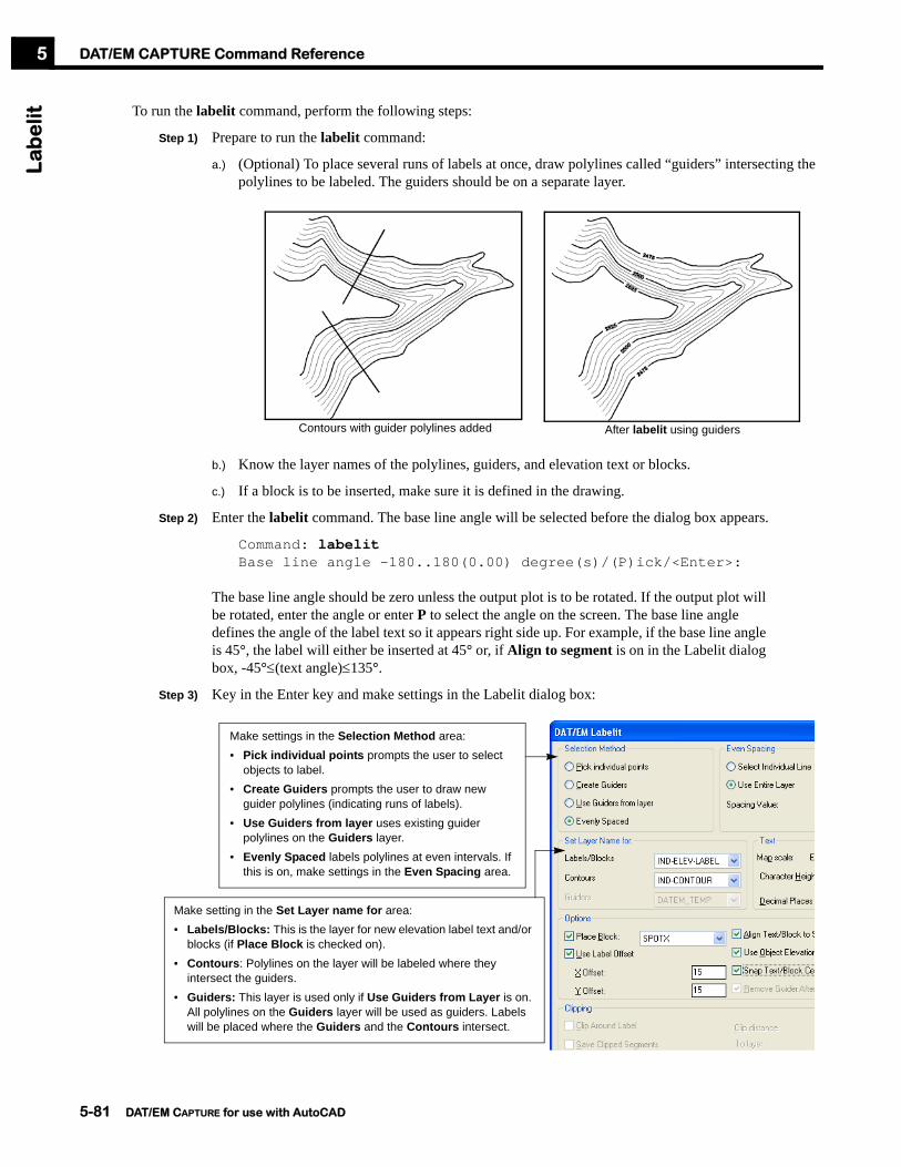
DAT/EM CAPTURE Command ReferenceL
ab
elit
5
To run the labelit command, perform the following steps:
Step 1) Prepare to run the labelit command:
a.) (Optional) To place several runs of labels at once, draw polylines called “guiders” intersecting the polylines to be labeled. The guiders should be on a separate layer.
b.) Know the layer names of the polylines, guiders, and elevation text or blocks.
c.) If a block is to be inserted, make sure it is defined in the drawing.
Step 2) Enter the labelit command. The base line angle will be selected before the dialog box appears.
Command: labelitBase line angle -180..180(0.00) degree(s)/(P)ick/<Enter>:
The base line angle should be zero unless the output plot is to be rotated. If the output plot will be rotated, enter the angle or enter P to select the angle on the screen. The base line angle defines the angle of the label text so it appears right side up. For example, if the base line angle is 45°, the label will either be inserted at 45° or, if Align to segment is on in the Labelit dialog box, -45°≤(text angle)≤135°.
Step 3) Key in the Enter key and make settings in the Labelit dialog box:
Contours with guider polylines added After labelit using guiders
Make settings in the Selection Method area:• Pick individual points prompts the user to select
objects to label.• Create Guiders prompts the user to draw new
guider polylines (indicating runs of labels).• Use Guiders from layer uses existing guider
polylines on the Guiders layer.• Evenly Spaced labels polylines at even intervals. If
this is on, make settings in the Even Spacing area.
Make setting in the Set Layer name for area:• Labels/Blocks: This is the layer for new elevation label text and/or
blocks (if Place Block is checked on).• Contours: Polylines on the layer will be labeled where they
intersect the guiders.• Guiders: This layer is used only if Use Guiders from Layer is on.
All polylines on the Guiders layer will be used as guiders. Labels will be placed where the Guiders and the Contours intersect.
5-81 DAT/EM CAPTURE for use with AutoCAD
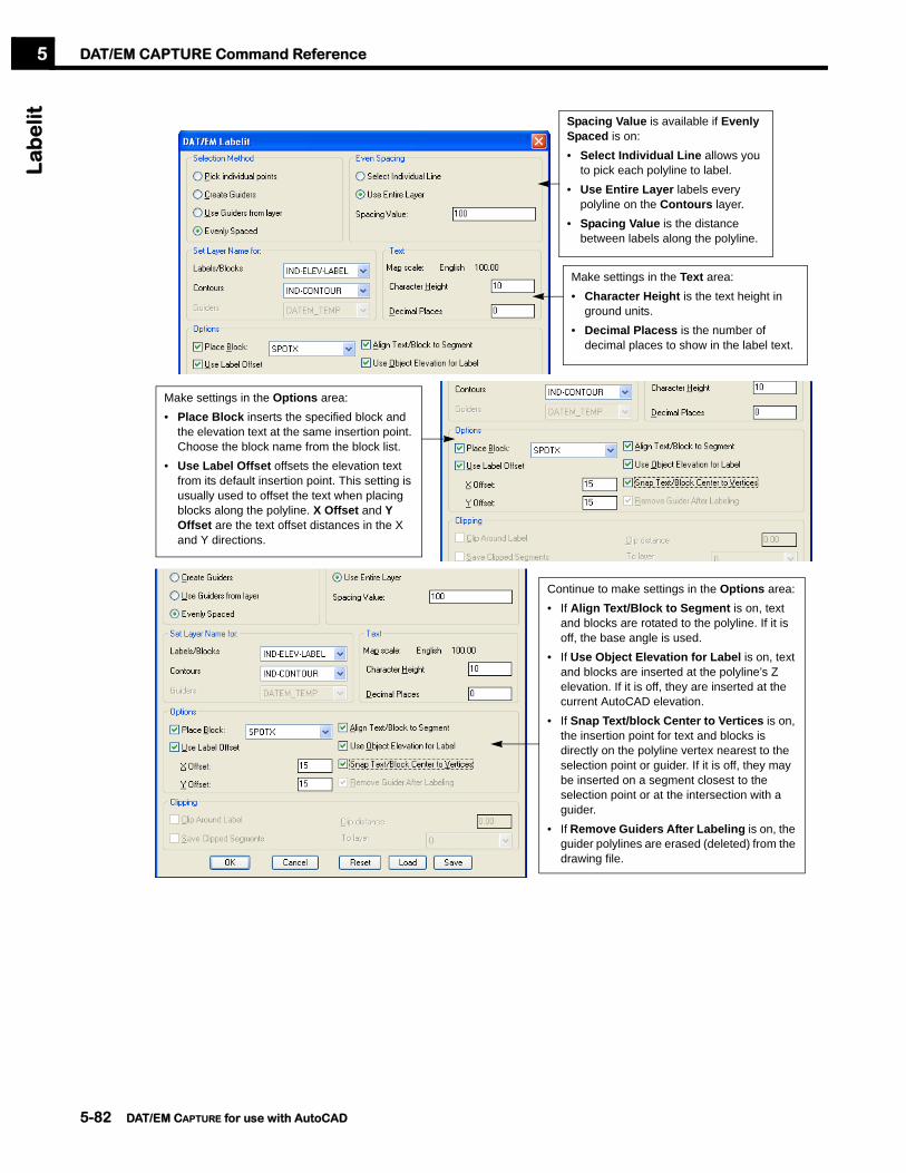
DAT/EM CAPTURE Command ReferenceL
ab
elit
5
Spacing Value is available if Evenly Spaced is on:• Select Individual Line allows you
to pick each polyline to label.• Use Entire Layer labels every
polyline on the Contours layer.• Spacing Value is the distance
between labels along the polyline.
Make settings in the Text area:• Character Height is the text height in
ground units.• Decimal Placess is the number of
decimal places to show in the label text.
Make settings in the Options area:• Place Block inserts the specified block and
the elevation text at the same insertion point. Choose the block name from the block list.
• Use Label Offset offsets the elevation text from its default insertion point. This setting is usually used to offset the text when placing blocks along the polyline. X Offset and Y Offset are the text offset distances in the X and Y directions.
Continue to make settings in the Options area:• If Align Text/Block to Segment is on, text
and blocks are rotated to the polyline. If it is off, the base angle is used.
• If Use Object Elevation for Label is on, text and blocks are inserted at the polyline’s Z elevation. If it is off, they are inserted at the current AutoCAD elevation.
• If Snap Text/block Center to Vertices is on, the insertion point for text and blocks is directly on the polyline vertex nearest to the selection point or guider. If it is off, they may be inserted on a segment closest to the selection point or at the intersection with a guider.
• If Remove Guiders After Labeling is on, the guider polylines are erased (deleted) from the drawing file.
5-82 DAT/EM CAPTURE for use with AutoCAD

DAT/EM CAPTURE Command ReferenceL
ab
elit
5
Step 4) If desired, use the Reset, Save, or Load buttons at any time.
Step 5) After finishing the settings in the Labelit dialog box, select OK.
Step 6) Follow the prompts to select or digitize objects. For example,
a.) If Pick individual points was selected, prompts appear:
Pick point on contour/(Esc): (pick polyline where text will be inserted)Pick point on contour/(Esc): (repeat until finished, then enter <Esc>).
b.) If Create guiders was selected, draw one or more guiders at the prompts,
Guider from point:Guider to point/(U)ndo: (pick)Guider to point/(U)ndo: (pick until finished, U to undo the last vertex)Guider to point/(U)ndo: <Enter># polyline(s) for labeling found on layer Name.Guider from point: (pick points for another guider, or press <Enter> to end)
c.) If Guiders exist, select layers was selected, the program runs and finishes.
Make settings in the Clipping area (only available if Place Block is off):• Turn on Clip Around Label to break and
remove the polylines under the text.• Turn on Save Clipped Segments to save
any clipped segments.• Set the To layer field to the layer to store
the clipped segments.• Set Clip distance to the width of the gap
around the text.
• Save saves the current dialog box settings.• Load restores the settings saved earlier by the Save button.• Reset restores the system defaults to the dialog box.
5-83 DAT/EM CAPTURE for use with AutoCAD

DAT/EM CAPTURE Command ReferenceL
c5
The lc command inserts AutoCAD blocks into the drawing at all control points coordinates found in the currently active ground control listing.
The file that lists the control points varies depending on the type of stereoplotter. For analog stereoplotters, the currently loaded ground control .con file is used. For analytical or digital stereoplotters, DAT/EM CAPTURE reads the stereoplotter’s control points and writes a file called control.con into the DAT/EM folder. This file is created specifically for the lc command.
To use the lc command, perform the following steps:
Step 1) Make sure the desired control blocks exist in the drawing file.
Step 2) Start the lc command:
Command: lc
Step 3) If a file finding dialog box appears, select a control file, then select OK.
Step 4) A dialog box appears. Make block and text settings.
Make settings in the dialog box, then select the OK button. The control points will be inserted followed by a zoom so that the control points appear in the view.
LcPurpose: To insert control point block symbols at all the coordinate locations read from the currently active orientation
control listing. (To insert selected points from a selected control file, see the Lcf command on page 5-85.)
If insert Block is checked Off, then an AutoCAD POINT will be inserted at the control point coordinate.
x, y, and z location results
Point Name result
Insert Block result
5-84 DAT/EM CAPTURE for use with AutoCAD

DAT/EM CAPTURE Command ReferenceL
cf
5
The lcf command inserts blocks into the drawing at selected control point locations from a selected control file. To use the lcf command, perform the following steps:
Step 1) Make sure the desired control blocks exist in the drawing file.
Step 2) Start the lcf command:
Command: lcf
Step 3) A file open dialog box appears. Select the control file.
Step 4) Use the arrow buttons to select the points to be inserted:
Step 5) Make block and text settings. This is the same dialog box that the lc command produces:
Step 6) When the settings are correct, select the OK button.
The control points will be inserted followed by a zoom so that the control points appear in the view.
LcfPurpose: To insert control point block symbols at selected coordinate locations read from a selected control file. (To
insert all points from the currently active orientation control file, see the Lc command on page 5-84.)
Highlight control point names and use the arrow buttons to select points.
If insert Block is checked Off, then an AutoCAD POINT will be inserted at the control point coordinate.
x, y, and z location results
Point Name result
Insert Block result
5-85 DAT/EM CAPTURE for use with AutoCAD

DAT/EM CAPTURE Command ReferenceL
ine
slo
pe
5
The lineslope command requires two points to be digitized at the bottom and the top of a slope; it inserts a line and text showing the percent grade, calculated by:
% grade = [(Z change) ÷ (XY change)]*100.
To use the lineslope command, perform the following steps:
Step 1) If necessary, load the ...Program Files\AutoCAD (version)\Datem\Measure(version).arx file. To load the file, use the appload command or select Load Application from AutoCAD’s Tools pull-down menu.
Step 2) Start the Setup command and review the settings for Map Scale, Block Scale Factor, and Text Scale Factor. These settings affect the size of the blocks and text placed by lineslope.
Step 3) Start the lineslope command:
Command: lineslope
Step 4) Make settings in the dialog:
Step 5) Select the Start button. Follow the prompts to digitize the bottom and top of a slope.
Step 6) Repeat to digitize any number of slope lines. If desired, use a osnap endpoint snap to connect the new line to the end of a previous line.
Step 7) When finished, select the Stop button and select the “X” button at the upper right of the dialog.
LineslopePurpose: To digitize points at the bottom and top of a slope, place a line, place optional end blocks, and place optional
text labels indicating the percent grade and the distance.
Select Start to begin digitizing. Select Stop to pause; select “x” to completely turn off the command.
Digitize the first point at the bottom of the slope.
Digitize the second point at the top of the slope.
Repeat. If desired, snap to the endpoint of a previous line.
5-86 DAT/EM CAPTURE for use with AutoCAD

DAT/EM CAPTURE Command ReferenceL
pat
5
Before starting any block patterning command, perform the following:
• Set the layer for the new blocks.
• Use the setup command to verify the Block scale factor and Block rotation angle and select the desired Planimetric Patterning setting.
Select the keypad or menu item, or type lpat. The computer prompts:
Command: lpatBlock name/?
Enter the name of the block to insert at intervals along each selected polyline.
Select objects <Last>:
Choose one or more polylines or enter L to select the most recently digitized object. The computer then prompts:
(T)oggle side/(B)lock scale=#/(P)attern dist=# <Enter>:
The blocks appear visually along the polyline, but are not permanent objects until <Enter> is pressed. Several options may be changed before the blocks are actually inserted:
• To instantly change the direction of the blocks, enter T.
• To change the block size, enter B and set a new scale.
• To change the block pattern spacing, enter P and set the new spacing in ground units.
When the blocks are correct, press <Enter> to accept them.
LpatPurpose: To insert a specified block symbol at intervals along a polyline. On polylines that are shorter than the block
interval, at least one block will be inserted.
All blocks inserted at the same elevation!If on (checked), all the blocks will be inserted as follows:•For 2D polylines: at the polyline’s Z•For 3D polylines: at Z=0 and evenly spaced in the (X,Y) plane.
Blocks inserted at the polyline elevation.If off (not checked), the blocks will be inserted at the polyline Z. On 3D polylines, the elevation will be interpolated along the polyline segment.
Any block may be used
(from the setup box)
5-87 DAT/EM CAPTURE for use with AutoCAD

DAT/EM CAPTURE Command ReferenceM
ea
sure
He
igh
t5
The measureheight command requires two points to be digitized at the base and the top of an object. It inserts a block and text showing the location and height.
To use the measureheight command, perform the following steps:
Step 1) If necessary, load the ...Program Files\AutoCAD (version)\Datem\Measure(version).arx file. To load the file, use the appload command or select Load Application from AutoCAD’s Tools pull-down menu.
Step 2) Start the Setup command and review the settings for Map Scale, Block Scale Factor and Text Scale Factor. These settings affect the size of the block and text placed by measureheight.
Step 3) Start the measureheight command:
Command: measureheight
Step 4) Make settings in the dialog:
Step 5) Select the Start button. Follow the prompts to digitize the base and top of an object.
Step 6) Repeat to digitize the height of any number of objects.
Step 7) When finished, select the Stop button and select the “X” button at the upper right of the dialog.
MeasureHeightPurpose: Digitize points at the base and top of an object; place a block to show the location and text to show the height
in ground units.
Select and existing layer, or key in a new layer name to be created.Place at top Z places the point or
block at the higher digitized point. If this setting is off, it will be placed at the lower digitized point.
If Rotate Kappa is on, the text is placed at the current SUMMIT EVOLUTION model’s kappa angle.
Select and existing layer, or key in a new layer name to be created.
Choose whether to place a point or a block.
Digitize the first point at the base of the object.
Digitize the second point at the top of the object.
Text is placed near the base or top of the object, depending on the Place at Top Z settings.
5-88 DAT/EM CAPTURE for use with AutoCAD

DAT/EM CAPTURE Command ReferenceM
orp
he
xpo
rte
r5
The morphexporter command exports AutoCAD morphological objects, such as DTM points, breaklines, spot heights, exclusion areas, and buildings, into an Inpho-format .wnp file. This file may then be used by the Inpho’s MATCH-T software to create a more accurate DTM point distribution.
To run morphexporter, perform the following steps:
Step 1) If necessary, load ...Program Files\AutoCAD (version)\Datem\MorphExporter(version).arx. To load the file, use the appload command or select Load Application from AutoCAD’s Tools pull-down menu.
Step 2) Collect morphological data as objects into the AutoCAD file. These may be 2D or 3D polylines on specific levels that describe the following data types:
Step 3) Start the morphexporter command.
Command: morphexporter
Step 4) Make settings in the dialog box:
Step 5) Select Export to create the .wnp file.
Step 6) If desired, view the new file using the Launch notepad to examine exported file button. Be aware that if the file is very large, Notepad will take a long time to load the file into memory.
Step 7) When completely finished, select Close. Use the output file later as input for MATCH-T.
MorphexporterPurpose: Export AutoCAD morphological objects into an Inpho GmbH-format .wnp file. This file may then be used by
Inpho’s MATCH-T software.
• DTM masspoints• Spot heights
• Border line polygons• Exclusion line polygons
• Break lines
Click on the (Click to Select) text or the existing layer list to activate the layer choices. Check on/off layers to build the layer list for that data type.
If (Click to Select) appears, there are no layers selected for that data type, and that data type will be omitted from the output file.
Browse/select a name for the new .wnp file.
Check the options:• Check on Text to include text
entities on specified layers.• Check on Blocks to include block
entities on specified layers.
Select Export to create the output file.
If needed, use this button to launch the AutoCAD Layer Properties Manager.
5-89 DAT/EM CAPTURE for use with AutoCAD

DAT/EM CAPTURE Command ReferenceM
ove
byp
ick
5
The movebypick command moves an analytical or digital stereoplotter with software-controlled move capabilities to a point picked by the mouse.
To activate the command, select the keypad key or enter,
Command: movebypick
A prompt appears to pick the point with the mouse. Select a point with the mouse digitizer. The analytical or digital stereoplotter moves to the selected point.
MovebypickPurpose: To move the analytical or digital stereoplotter to a point picked by the mouse.
See also: Contourdown, Contourup, Datmove, Zmove
5-90 DAT/EM CAPTURE for use with AutoCAD

DAT/EM CAPTURE Command ReferenceO
pe
nU
p5
Perform the following steps:
Step 1) Start the command:
Command: openupSelect polyline(s) [All/Last/Previous/Remove closing segment[now
on]]:
Step 2) If necessary, change the Remove closing segment option. Enter R to toggle the setting.
Step 3) Select one or more polylines using either the cursor of one of the key-ins, A, L, or P.
Step 4) Press the Enter key to run the command.
OpenUpPurpose: To open one or more closed polylines. Choose to either keep or remove the closing segment.
Original closed polyline
After opening with Remove closing segment option on
After opening with Remove closing segment option off
first vertex
5-91 DAT/EM CAPTURE for use with AutoCAD

DAT/EM CAPTURE Command ReferenceO
psq
r2d
5
In psqr and psqr3d, the sides of each building are squared to the first segment drawn on that building. With the “orthogonal” squaring function opsqr2d, all buildings are squared to a pre-defined base angle. Opsqr2d is useful when many buildings are aligned with each other or with a street.
The psqr command uses a 2D polyline. Each vertex has the same elevation as the first point. To use a 3D polyline, see Opsqr3d and Psqr3d.
To use opsqr2d, perform the following steps:
Step 1) Use the Setup command to make building squaring selections. set the Building squaring tolerance and Automatically Close settings. For more information about Setup, see page 5-112. For information about the Building squaring tolerance, see “Notes About the Squaring Angle for Psqr, Psqr3d, Opsqr2d, Opsqr3d” on page 5-102.
Step 2) Start the command:
Command: opsqr2dBase angle (default) degrees -90..90/(P)ick /<Enter>:
The Base angle setting will be used to align the buildings. To accept the default, press <Enter>. To change it, either enter the angle on the keyboard, or enter P and pick two points to define the angle.
Step 3) To the “Square From point/Xy tol: ” prompt, make new settings if desired. The default Xy tolerance is the currently set building squaring angle. For details on how this angle works, see “Notes About the Squaring Angle for Psqr, Psqr3d, Opsqr2d, Opsqr3d” on page 5-102. To change the default setting in the future, see “Setup” on page 5-112. To change it for the current building, enter X and enter a new angle.
Opsqr2dPurpose: To digitize buildings using 2D polylines and align them orthogonally to a specified angle.
Base angle, 37°
Side exceeds the squaring angle
5-92 DAT/EM CAPTURE for use with AutoCAD

DAT/EM CAPTURE Command ReferenceO
psq
r2d
5
The digitizing process and prompts are exactly the same as for “Psqr” on page 5-101, except it is not necessary to digitize the longest side of a building first.
Step 4) Digitize the first corner, then digitize successive corners as follows:
a.) For rectangular buildings, digitize only the first three corners. Press <Enter> (on the keyboard or a programmed switch). It will fill in the two missing sides if Automatically Close is set on (see Step 1), but it will fill in one missing side if Automatically Close is set off. Note: To override the Automatically Close off setting, enter a C to fill in two missing sides and close.
b.) For buildings with more than four segments, digitize each corner. Press <Enter> to fill in the one missing side if Automatically Close is set on (see Step 1). If Automatically Close is set off, the polyline simply ends. Note: To override the Automatically Close off setting, enter a C to force the polyline to close.
c.) After the first three corners have been digitized, U may be entered to undo the last digitized corner. Every corner may be removed except the first two corners. Resume digitizing at any time.
Step 5) If desired, continue digitizing more buildings.
Step 6) To completely end the command, press <Enter> a second time.
Note for Psqr, Psqr3d, Opsqr2d, and Opsqr3dDigitize building corners, not sides.
Do not try to end by picking the starting vertex. Graphically, the building will be missing one or two sides, but it will be completed when <Enter> is pressed.
See also: Opsqr3d, Psqr, Psqr3d
Point 1
Point 2
Point 3, <Enter>Result
Point 1
Point 8, <Enter>
2
3 4
56
7
Result
5-93 DAT/EM CAPTURE for use with AutoCAD

DAT/EM CAPTURE Command ReferenceO
psq
r3d
5
In psqr and psqr3d, the sides of each building are squared to the first segment drawn on that building. With the “orthogonal” squaring function opsqr3d, all buildings are squared to pre-defined base angle. Opsqr3d is useful when many buildings are aligned with each other or with a street.
The digitizing prompts for opsqr3d are exactly the same as for opsqr2d and psqr. There are two differences between the commands:
• Opsqr3d uses a 3D polyline instead of a 2D polyline. Each building vertex obtains the digitizer elevation at the time it was digitized.
• The Z tolerance and Pitched settings entered in the Setup box apply to opsqr3d and psqr3d. They enable vertical segments between rooflines that drop to different elevation levels.
To use opsqr3d, perform the following steps:
Step 1) Use the Setup command to make building squaring selections. set the Building squaring tolerance, Z tolerance, Pitched or Flat, and Automatically Close settings. For more information about Setup, see page 5-112. For information about the Building squaring tolerance, see “Notes About the Squaring Angle for Psqr, Psqr3d, Opsqr2d, Opsqr3d” on page 5-102.
Step 2) Start the command:
Command: opsqr3dBase angle (default) degrees -90..90/(P)ick /<Enter>:
The Base angle setting will be used to align the buildings. To accept the default, press <Enter>. To change it, either enter the angle on the keyboard, or enter P and pick two points to define the angle.
Step 3) To the “Square From point/Xy tol/Z tol/Plotter z[ON]: ” prompt, make new settings if desired:
a.) To change the tolerance angles, enter X or Z and the new values.
b.) To use the stereoplotter’s current Z setting for each vertex, make sure Plotter z is ON. To toggle the Plotter z setting, enter P.
c.) Press <Enter> to return to digitizing.
Opsqr3dPurpose: To digitize buildings using 3D polylines and align them orthogonally to a specified angle.
Base angle, 37°
Side exceeds the squaring angle
5-94 DAT/EM CAPTURE for use with AutoCAD
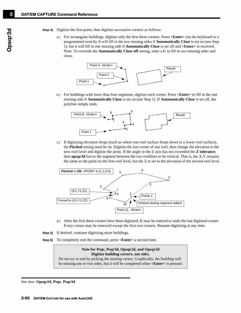
DAT/EM CAPTURE Command ReferenceO
psq
r3d
5
Step 4) Digitize the first point, then digitize successive corners as follows:
a.) For rectangular buildings, digitize only the first three corners. Press <Enter> (on the keyboard or a programmed switch). It will fill in the two missing sides if Automatically Close is set on (see Step 1), but it will fill in one missing side if Automatically Close is set off and <Enter> is received. Note: To override the Automatically Close off setting, enter a C to fill in two missing sides and close.
b.) For buildings with more than four segments, digitize each corner. Press <Enter> to fill in the one missing side if Automatically Close is set on (see Step 1). If Automatically Close is set off, the polyline simply ends.
c.) If digitizing elevation drops (such as where one roof surface drops down to a lower roof surface), the Pitched setting must be on. Digitize the last corner of one roof, then change the elevation to the new roof level and digitize the point. If the angle to the Z axis has not exceeded the Z tolerance, then opsqr3d forces the segment between the two rooflines to be vertical. That is, the X,Y remains the same as the point on the first roof level, but the Z to set to the elevation of the second roof level.
d.) After the first three corners have been digitized, U may be entered to undo the last digitized corner. Every corner may be removed except the first two corners. Resume digitizing at any time.
Step 5) If desired, continue digitizing more buildings.
Step 6) To completely end the command, press <Enter> a second time.
Note for Psqr, Psqr3d, Opsqr2d, and Opsqr3dDigitize building corners, not sides.
Do not try to end by picking the starting vertex. Graphically, the building will be missing one or two sides, but it will be completed when <Enter> is pressed.
See also: Opsqr2d, Psqr, Psqr3d
Point 1
Point 2
Point 3, <Enter>Result
Point 1
Point 8, <Enter>
7
6 5
43
2
Result
Forced to (X1,Y1,Z2)
(X1,Y1,Z1)
Pitched is ON, VPOINT is (1,1,0.5)
Points 1
2
3
45
6
89
10
Point 11, <Enter>
Vertical closing segment added
71
5-95 DAT/EM CAPTURE for use with AutoCAD

DAT/EM CAPTURE Command ReferenceO
psq
r3d
5
5-96 DAT/EM CAPTURE for use with AutoCAD
DAT/EM CAPTURE Command ReferenceO
rie
nt
5
The orient command is used automatically when the DATEM CAPTURE application is first loaded, but if necessary, it may be used at any other time to reestablish communication to AutoCAD. The orient command is very similar to resetting the digitizer using AutoCAD’s reinit command, except that it also sends the orientation information to the AutoCAD tablet. As it finishes, it runs Datemrotate so that north appears straight up on the AutoCAD view.
The orient_only command is similar to orient, but it does not run Datemrotate.
The orient or orient_only command may be helpful after communication between AutoCAD and DATEM CAPTURE is lost. That is, if moving the stereoplotter no longer moves the cursor or updates the coordinates in AutoCAD, then try the orient or orient_only command.
When the orient command is entered, messages appear in the AutoCAD text window. These message may seem familiar, because they are the same messages that were seen when the DATEM CAPTURE application was loaded.
Command: orientCalibrating tablet...Adjusting for Kappa...Regenerating model.
Because orient_only does not run Datemrotate, its messages show only the tablet calibration:
Command: orientCalibrating tablet...
If the communication was successfully reestablished, the stereoplotter should be in control of the cursor movement in AutoCAD. If desired, visit a control point to make sure the location matches the correct coordinates.
OrientOrient_Only
Purpose: To reestablish the communication between AutoCAD and the stereoplotter and to send the stereoplotter’s orientation to AutoCAD.
5-97 DAT/EM CAPTURE for use with AutoCAD
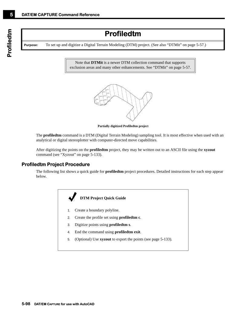
DAT/EM CAPTURE Command ReferenceP
rofi
led
tm5
Partially digitized Profiledtm project
The profiledtm command is a DTM (Digital Terrain Modeling) sampling tool. It is most effective when used with an analytical or digital stereoplotter with computer-directed move capabilities.
After digitizing the points on the profiledtm project, they may be written out to an ASCII file using the xyzout command (see “Xyzout” on page 5-133).
Profiledtm Project ProcedureThe following list shows a quick guide for profiledtm project procedures. Detailed instructions for each step appear below.
ProfiledtmPurpose: To set up and digitize a Digital Terrain Modeling (DTM) project. (See also “DTMit” on page 5-57.)
Note that DTMit is a newer DTM collection command that supports exclusion areas and many other enhancements. See “DTMit” on page 5-57.
DTM Project Quick Guide
1. Create a boundary polyline.
2. Create the profile set using profiledtm c.
3. Digitize points using profiledtm s.
4. End the command using profiledtm exit.
5. (Optional) Use xyzout to export the points (see page 5-133).
5-98 DAT/EM CAPTURE for use with AutoCAD

DAT/EM CAPTURE Command ReferenceP
rofi
led
tm5
Digitize a Boundary PolylineBefore running the profiledtm command, digitize one or more boundaries for the project:
• A boundary may be a 2D or 3D closed polyline drawn around the area to be sampled.
• A boundary may be in any plane in 3D space.
• A boundary may be on any layer.
Sample Profiledtm boundary
Create the Profile SetAfter digitizing the boundary, use profiledtm create to calculate the profile set:
Command: profiledtmCreate/Sampling/Exit: c
Prompts appear asking for information about the profiles:
Parallel line distance: <default>: Rotation angle <default>:Layer name of profile lines:Show profile lines? (Y/N) <Y>:Select a polyline <Last>:
Select the boundary. The profiles will be drawn as parallel lines.
The profiledtm prompt appears again. More boundaries may be selected if desired.
Sample Profiledtm profiles (with dashed linetype)
5-99 DAT/EM CAPTURE for use with AutoCAD

DAT/EM CAPTURE Command ReferenceP
rofi
led
tm5
Digitize Points on the ProfilesTo digitize points along the profile lines, start the profiledtm sampling option, enter S, and choose settings:
Command: profiledtmCreate/Sampling/Exit: sLayer name of DTM points:Use Blocks? (Y=Blocks / N=Points) <Y>:Block name for DTM points? <SPOTX>/* for list>Elevation text label of each DTM point? (Y/N) <Y>:Drive: Locked, Incremental, Both, Manual? (L,I,B,M) <I>:
The following table shows the results of each drive mode choice and instructions for digitizing:
Drive Mode Results
Locked If Locked is selected, the stereoplotter’s axis will be locked so that the cursor can only move along the current profile line. Locked is software controlled on analytical and digital stereoplotters, but must be used with a mechanical axis-locking device on an analog stereoplotter. When Locked is selected, the following additional prompt appears:
Undo/Next/Back/Finish (U/N/B/F) <pick>:
Move the stereoplotter along the profile and digitize points as desired.
•To digitize break points, move to the desired point along the profile and digitize, then use Back increment or Next to return to the desired increment.
•To remove the last point, enter U to undo. Undo may be repeated.
Incremental If Incremental is selected, the stereoplotter automatically drives to the sampling locations. Incremental may be used with analytical and digital stereoplotters with computer-driven movement capabilities. When Incremental is selected, the following prompts appear:
Profile increment distance? <default>:Skip/Back increment/Undo/Next/Finish (S/B/U/N/F) <pick>:
The stereoplotter drives to the profile increment points. After the point is digitized, the stereoplotter moves to the next increment.
•To go to the next profile, enter S to skip.•To digitize break points, move to the desired point and digitize, then use Back
increment or Next to return to the desired increment.•To remove the last point, enter U to undo. Undo may be repeated.
Both If Both is selected, the analytical or digital stereoplotter will be placed in lock mode, but will be driven by increments along the profile. Both provides the same prompt choices as for Increment mode, but movement will be restricted to be along the profile line.
Manual If Manual selected, the user must move the stereoplotter to the sampling locations. Manual may be used for analog stereoplotters and for analytical stereoplotter without computer-driven movement capabilities. For the Manual selection, another prompt appears:
Undo last point/Finish (U/F) <pick>:
the user must position the stereoplotter on the first profile location. Sample points using the digitizing switch. To remove the last point, enter U to undo. Undo may be repeated.
See also: Capt3d, DTMit
5-100 DAT/EM CAPTURE for use with AutoCAD

DAT/EM CAPTURE Command ReferenceP
sqr
5
The psqr command uses a 2D polyline. Each vertex has the same elevation as the first point. To use a 3D polyline, see Opsqr3d and Psqr3d.
To use psqr, perform the following steps:
Step 1) Select whether or not to have the polyline close as the command finishes. Use the Setup command and set Automatically Close on or off. For more information about Setup, see page 5-112.
Step 2) Start psqr. Press a keypad or menu key, or type
Command: psqr
Step 3) Digitize the two corners by the longest side of the building. Choosing the longest side first helps to more accurately define the base angle of the building. Then digitize successive corners as follows:
a.) For rectangular buildings, digitize only the first three corners. Press <Enter> (on the keyboard or a programmed switch). It will fill in the two missing sides if Automatically Close is set on (see Step 1), but it will fill in one missing side if Automatically Close is set off. Note: To override the Automatically Close off setting, enter a C to fill in two missing sides and close.
b.) For buildings with more than four segments, digitize each corner. Press <Enter> to fill in the one missing side if Automatically Close is set on (see Step 1). If Automatically Close is set off, the polyline simply ends. Note: To override the Automatically Close off setting, enter a C to force the polyline to close.
c.) After the first three corners have been digitized, U may be entered to undo the last digitized corner. Every corner may be removed except the first two corners. Resume digitizing at any time.
Step 4) If desired, continue digitizing more buildings.
Step 5) To completely end the command, press <Enter> a second time.
PsqrPurpose: To digitize and perform squaring on buildings and other man-made objects that have sides at right angles to
each other. Psqr uses 2D polylines.
Point 1
Point 2
Point 3, <Enter>Result
Point 1
Point 8, <Enter>
7
6 5
43
2
Result
5-101 DAT/EM CAPTURE for use with AutoCAD

DAT/EM CAPTURE Command ReferenceP
sqr
5
Notes About the Squaring Angle for Psqr, Psqr3d, Opsqr2d, Opsqr3dPsqr squares building sides according to the currently set building squaring angle. The tolerance is entered in the setup dialog box (see “Setup” on page 5-112).
The building squaring angle units are in decimal degrees. During building squaring, if a building side is less than the tolerance angle from square with respect to the previous side, then it is adjusted to be perpendicular to the previous side. The tolerance should be set so the majority of buildings will be squared nicely, while unusually shaped buildings retain their actual angles. The best tolerance for the drawing may depend on the map scale.
The following diagrams show how the squaring angle works:
Points picked for the first four building corners (incomplete building)
Result of Psqr if the squaring angle is 15° (incomplete building)
Note for Psqr, Psqr3d, Opsqr2d, and Opsqr3dDigitize building corners, not sides.
Do not try to end by picking the starting vertex. Graphically, the building will be missing one or two sides, but it will be completed when <Enter> is pressed.
5-102 DAT/EM CAPTURE for use with AutoCAD

DAT/EM CAPTURE Command ReferenceP
sqr
5
Result of Psqr if the squaring angle is 6° (incomplete building)
See also: Opsqr2d, Opsqr3d, Psqr3d
5-103 DAT/EM CAPTURE for use with AutoCAD

DAT/EM CAPTURE Command ReferenceP
sqr3
d5
The prompts for psqr3d are exactly the same as for psqr. There are two differences between the commands:
• Psqr3d uses a 3D polyline instead of a 2D polyline. Each building vertex obtains the digitizer elevation at the time it was digitized.
• The Z tolerance and Pitched settings entered in the Setup box apply to opsqr3d and psqr3d. They enable vertical segments between rooflines that drop to different elevation levels.
To use psqr3d, perform the following steps:
Step 1) Use the Setup command to make building squaring selections. set the Building squaring tolerance, Z tolerance, Pitched or Flat, and Automatically Close settings. For more information about Setup, see page 5-112. For information about the Building squaring tolerance, see “Notes About the Squaring Angle for Psqr, Psqr3d, Opsqr2d, Opsqr3d” on page 5-102.
Step 2) Start the command:
Command: psqr3d
Step 3) Digitize the two corners by the longest side of the building. Choosing the longest side first helps to more accurately define the base angle of the building. Then digitize successive corners as follows:
a.) For rectangular buildings, digitize only the first three corners. Press <Enter> (on the keyboard or a programmed switch). It will fill in the two missing sides if Automatically Close is set on (see Step 1), but it will fill in one missing side if Automatically Close is set off. Note: To override the Automatically Close off setting, enter a C to fill in two missing sides and close.
Psqr3dPurpose: To digitize and perform squaring on buildings and other man-made objects that have sides at right angles to
each other. Psqr3d uses 3D polylines.
Point 1
Point 2
Point 3, <Enter>Result
5-104 DAT/EM CAPTURE for use with AutoCAD

DAT/EM CAPTURE Command ReferenceP
sqr3
d5
b.) For buildings with more than four segments, digitize each corner. Press <Enter> to fill in the one missing side if Automatically Close is set on (see Step 1). If Automatically Close is set off, the polyline simply ends. Note: To override the Automatically Close off setting, enter a C to force the polyline to close.
c.) If digitizing elevation drops (such as where one roof surface drops down to a lower roof surface), the Pitched setting must be on. Digitize the last corner of one roof, then change the elevation to the new roof level and digitize the point. If the angle to the Z axis has not exceeded the Z tolerance, then opsqr3d forces the segment between the two rooflines to be vertical. That is, the X,Y remains the same as the point on the first roof level, but the Z to set to the elevation of the second roof level.
d.) After the first three corners have been digitized, U may be entered to undo the last digitized corner. Every corner may be removed except the first two corners. Resume digitizing at any time.
Step 4) If desired, continue digitizing more buildings.
Step 5) To completely end the command, press <Enter> a second time.
Note for Psqr, Psqr3d, Opsqr2d, and Opsqr3dDigitize building corners, not sides.
Do not try to end by picking the starting vertex. Graphically, the building will be missing one or two sides, but it will be completed when <Enter> is pressed.
See also: Opsqr2d, Opsqr3d, and Psqr
Point 1
Point 8, <Enter>
7
6 5
43
2
Result
Forced to (X1,Y1,Z2)
(X1,Y1,Z1)
Pitched is ON, VPOINT is (1,1,0.5)
Points 1
2
3
45
6
89
10
Point 11, <Enter>
Vertical closing segment added
71
5-105 DAT/EM CAPTURE for use with AutoCAD

DAT/EM CAPTURE Command ReferenceR
eve
rse
5
To reverse the vertex order of one or more polylines, use the reverse command:
Command: reverseSelect objects to reverse:
Choose one or more polylines. Direction arrows indicating the original direction appear on each polyline as it is selected. Press <Enter> to process the selected polylines. The vertices of each polyline will be reversed.
• Any kind of 2D or 3D polyline may be used with this command.
• Arcs may be contained in the polyline.
• SPLINEs may NOT be used.
ReversePurpose: Reverse polyline vertex order.
5-106 DAT/EM CAPTURE for use with AutoCAD

DAT/EM CAPTURE Command ReferenceR
oa
d5
To offset a road edge polyline with curb and gutter polylines, perform the following steps:
Step 1) Digitize a polyline along one side of the road.
Step 2) Set the layer for the new polylines.
Step 3) Start the road command:
Command: roadSelect a polyline <Last>:
Step 4) Select the polyline that was digitized along one side of the road.
Step 5) Follow the prompts to enter information about the curb and gutter distances:
Select a road side Right/<Left>:Enter the road width <>:Enter curb height <>:Enter curb width <>:Enter gutter width <>:
The new offset polylines will be drawn in the file.
RoadPurpose: Starting with one road edge polyline, offset a complete set of curb and gutter polylines.
The Curb command offers more options!
To place the offsets on different layers or to start with a road center line, use the curb command.
See also: 3doffset, 3doffsetmeasure, Curb
After road adds curb and gutter offsets.(Total 8 polylines. Offset distances exaggerated)
Road edge polyline before road command.(Total 1 polyline.)
5-107 DAT/EM CAPTURE for use with AutoCAD

DAT/EM CAPTURE Command ReferenceR
r5
Before starting any block patterning command, perform the following:
• Set the layer for the new objects.
• Use the setup command to verify the Block scale factor and Block rotation angle and select the Planimetric Patterning setting.
To draw a railroad as a double polyline and insert railroad ticks along it, perform the following steps:
Step 1) Digitize one side of the track with a 2D or 3D polyline.
Step 2) Choose a method of running the rr command:
a.) To complete the track immediately after digitizing the right side, select 2 Line RR Last on a DAT/EM KEYPAD key or menu item.
b.) Or, enter rr and select one or more rails to pattern and offset.
Command: rrSelect objects <Last>:
Choose one or more rail polylines or enter L to select the most recently digitized object.
Track Width <#>:Tie Length <#>:(T)oggle side/(W)idth=#/(L)ength=#/(P)attern=# <Enter>:
The blocks and offset rail appear visually along the polyline, but are not permanent until <Enter> is pressed. Several options may be changed before the blocks are inserted:
• To instantly change the side of the offset and the direction of the blocks, enter T.
• To change track width, enter W and set a new width.
• To change the tie length, enter L and set a new length.
• To change the block pattern spacing, enter P and set the new spacing factor.
• When the offset and blocks are correct, press <Enter> to accept them.
The file is searched for the block RRTICK. If it doesn't already exist, it is created.
RrPurpose: After the user digitizes one side of a railroad track, rr offsets the opposite rail and inserts railroad tick blocks
at intervals along the track.
All blocks inserted at the same elevation!If on (checked), all the blocks will be inserted as follows:•For 2D polylines: at the polyline’s Z•For 3D polylines: at Z=0 and evenly spaced in the (X,Y) plane.
Blocks inserted at the polyline elevation.If off (not checked), the blocks will be inserted at the polyline Z. On 3D polylines, the elevation will be interpolated along the polyline segment.
See also: Rr100
(from the setup box)
5-108 DAT/EM CAPTURE for use with AutoCAD

DAT/EM CAPTURE Command ReferenceR
r10
05
Before starting any block patterning command, perform the following:
• Set the layer for the new objects.
• Use the setup command to verify the Block scale factor and Block rotation angle and select the Planimetric Patterning setting.
To insert railroad ticks on a railroad shown as a single polyline down the center of the track, perform the following steps:
Step 1) Digitize the center of the track with a 2D or 3D polyline.
Step 2) Choose a method to run the rr100 command:
a.) To pattern the track immediately after digitizing the center, select 1 Line RR Last on the DAT/EM KEYPAD or on a menu item.
b.) Or, enter RR100 and then pick on or more tracks to pattern.
Command: rr100Select objects <Last>:
Choose one or more rail centerline polylines or enter L to select the most recently digitized object. The computer then prompts:
(B)lock scale=#/(P)attern dist=# <Enter>:
The blocks appear visually along the polyline, but are not permanent objects until <Enter> is pressed. Several options may be changed before the blocks are actually inserted:
• To change tick size, enter B and set a new scale.
• To change the block pattern spacing, enter P and set the new spacing factor.
• When the offset and blocks are correct, press <Enter> to accept them.
The file is searched for the block RRTICK100. If it doesn't already exist, it is created.
Rr100Purpose: After the user digitizes a single polyline down the center of a railroad track, rr100 adds railroad tick blocks at
intervals along the track.
All blocks inserted at the same elevation!If on (checked), all the blocks will be inserted as follows:•For 2D polylines: at the polyline’s Z•For 3D polylines: at Z=0 and evenly spaced in the (X,Y) plane.
Blocks inserted at the polyline elevation.If off (not checked), the blocks will be inserted at the polyline Z. On 3D polylines, the elevation will be interpolated along the polyline segment.
See also: Rr
(from the setup box)
5-109 DAT/EM CAPTURE for use with AutoCAD

DAT/EM CAPTURE Command ReferenceS
etO
bje
ctZ
5
The SetObjectZ command accepts most object types as input.
Perform the following steps:
Step 1) If using the system mouse to digitize, use AutoCAD’s elev command to set the desired elevation.
Step 2) Start the command:
Command: setobjectzPlease measure object at its new elevation/Undo:
Step 3) If using the stereoplotter to digitize, set the stereoplotter’s floating mark to the desired elevation.
Step 4) Position the cursor over an object and digitize. Repeat as desired.
Step 5) To undo the last change, enter Undo or _u. Undo may be used multiple times until the first change of the current command session has been undone.
Step 6) To exit the command prompt, press the <Enter> key or the spacebar.
SetObjectZPurpose: To change the elevation of an object. For objects that have multiple vertices at varying elevations, it offsets
each vertex by the elevation difference (instead of flattening all elevations to the same value).
5-110 DAT/EM CAPTURE for use with AutoCAD

DAT/EM CAPTURE Command ReferenceS
etP
oin
tBlo
ckZ
5
The SetPointBlockZ command accepts both points and blocks as input. The SetBlockZ command accepts only blocks, and the SetPointZ command accepts only points.
For elevation-only changes, these commands are faster to use than AutoCAD’s move and change commands.
Perform the following steps:
Step 1) If using the system mouse to digitize, use AutoCAD’s elev command to set the desired elevation.
Step 2) Enter the desired command: SetPointBlockZ to change any combination of blocks and points, SetBlockZ to change blocks only, or SetPointZ to change points only.
Command: setpointblockzPlease measure object at its new elevation/Undo:
Step 3) If using the stereoplotter to digitize, set the stereoplotter’s floating mark to the desired elevation.
Step 4) Position the cursor over the point or the block’s graphics and digitize.
Step 5) Repeat setting the elevation and digitizing more points and/or blocks.
Step 6) To undo the last change, enter Undo or _u. Undo may be used multiple times until the first change of the current command session has been undone.
Step 7) To exit the command prompt, press the <Enter> key or the spacebar.
SetPointBlockZSetBlockZ, SetPointZ
Purpose: To quickly edit the elevation of a point or block. Assign the stereoplotter elevation if the stereoplotter is used, or assign AutoCAD’s elev setting if the system mouse is used.
5-111 DAT/EM CAPTURE for use with AutoCAD

DAT/EM CAPTURE Command ReferenceS
etu
p5
The DAT/EM Mapping Parameters dialog box should be activated as soon as AutoCAD is started. To activate the dialog box, use the setup command.
Command: setup
The settings in this box are as follows:
SetupPurpose: To change the settings listed in the DAT/EM capture parameters dialog box.
Scale The output plotting scale of the map. It is the “x” represented in the English scale 1”=x’ or the Metric (ratio) scale 1:x.
Units The choices are English units (for a scale of 1 inch = x feet) or Metric (for a ratio scale, 1:x). If using any kind of ratio scale, even if it is not called “metric,” set this box to Metric.
Beep on pick Check on this setting to have the computer beep each time a point is digitized.
Block rotation angle
Blocks will be rotated by this angle as they are inserted. This is a counterclockwise angle in decimal degrees.
Block scale factor As they are inserted, blocks will be scaled by this factor times the map scale.
Text scale factor As text is inserted, it will be scaled by this factor times the map scale.
5-112 DAT/EM CAPTURE for use with AutoCAD

DAT/EM CAPTURE Command ReferenceS
etu
p5
Prompt for Block Tag Info
When checked on, this setting causes block insertion commands such as INS to prompt for block tags to be entered. Prompts appear only for blocks that have block tag attributes in their definition. When checked off, all blocks are inserted without block tag attributes.
Pattern distance factor
On patterning commands such as fence and grail, the default patterning distance shown will be this factor times the map scale.
Planimetric patterning
This setting affects block elevation for patterning commands such as brush, dep, fence, grail, lpat, rr, rr100, slopetick, and wallfence.
All blocks inserted at the same elevation!If on (checked), all the blocks will be inserted as follows:•For 2D polylines: at the polyline’s Z•For 3D polylines: at Z=0 and evenly spaced in the (X,Y) plane.
Blocks inserted at the polyline elevation.If off (not checked), the blocks will be inserted at the polyline Z. On 3D polylines, the elevation will be interpolated along the polyline segment.
Building squaring, max(degrees)
This is the limit for the angle in the X,Y plane for the psqr, psqr3d, opsqr2d, opsqr3d commands. The units are in decimal degrees. For details, see “Psqr” on page 5-101.
Z Tolerance, max(degrees)
This is the angle in the X,Z plane for the psqr3d and opsqr3d commands. It allows two roof levels to be connected by a vertical segment. If two points are digitized and their angle to the Z axis does not exceed the Z tolerance, then the points are connected by a vertical segment. The units are in decimal degrees.
Pitched or Flat If pitched is on, psqr3d and opsqr3d will allow a vertical closing segment to be added between two roof levels. If flat is on, the closing segment will be between the last digitized point and the first point, and may have different X,Y, and Z values on each end (not necessarily vertical).
Automatically Close
If Automatically Close is on, then the psqr, psqr3d, opsqr2d, opsqr3d commands will add a closing segment when they are finished. If this setting is off, the polyline remains open. The “open” option may be useful for digitizing man-made objects that have square corners, but that are not buildings.
5-113 DAT/EM CAPTURE for use with AutoCAD
DAT/EM CAPTURE Command ReferenceS
etu
p5
Contour Interval The elevation contour interval. This will be used by capt2d to round the elevations of elevation contours. It will also be used on analytical or digital stereoplotters for moving up and down in elevation by the contour interval distance. See “Capt2d” on page 5-28, “Contourdown” on page 5-37, and “Contourup” on page 5-38.
Curvature angle, minimum (degrees)
This value sets the angle limit for digitizing a point in stream mode with capt2d and capt3d. For information on these commands, see “Capt2d” on page 5-28 and “Capt3d” on page 5-30. This angle is in decimal degrees.
XY distance, % of Map Scale
This value sets the maximum XY distance limit for digitizing a point in stream mode with capt2d and capt3d. For information on these commands, see “Capt2d” on page 5-28 and “Capt3d” on page 5-30.
Z distance, % of Map Scale
This value sets the minimum Z distance limit for digitizing a point in stream mode with capt2d and capt3d. For information on these commands, see “Capt2d” on page 5-28 and “Capt3d” on page 5-30.
Reset Call up the original DAT/EM CAPTURE-supplied default settings for this dialog box.
Load Load a different file containing settings.
Save Save a file containing the current settings.
5-114 DAT/EM CAPTURE for use with AutoCAD

DAT/EM CAPTURE Command ReferenceS
hif
t5
The shift command moves all the objects in the file.
To activate the command, enter shift,
Command: shift
Either enter the coordinate shift values in the dialog box or select Measure to select the shift with the digitizer. If Measure is selected, follow the prompts to digitize the shift:
Command: measurePick initial pointPick offset from initial point
After digitizing the two points, the dialog box will return showing the selected values.
To accept the shift, select OK.
ShiftPurpose: To move all the objects in the file by an (X,Y,Z) shift.
If desired, select Measure to select the shift with the digitizer.
5-115 DAT/EM CAPTURE for use with AutoCAD

DAT/EM CAPTURE Command ReferenceS
ho
t5
The shot command activates a special mode for inserting blocks or points. When a shot mode is set and a block name is entered with the ins command, blocks may be inserted with every one or two hits to the digitizing switch. An option allows points to be inserted instead.
Perform the following steps:
Step 1) Activate the command. Select one of the symbol insertion keys from the keypad, or enter the shot command,
Command: shot(O)ne/Rotate/Scale/All/Point:
Step 2) Choose an option:
a.) Enter the letter O to insert a block each time the digitizing switch is pressed.
b.) Enter R to insert a block after pressing the digitizing switch twice. The first pick will be the insertion point, and the second pick defines the block rotation angle.
c.) Enter S to insert a block after pressing the digitizing switch twice. The first pick will be the insertion point, and the second pick defines the block scale factor.
d.) Enter A to insert a block after pressing the digitizing switch twice. The first pick will be the insertion point, and the second pick defines both the rotation angle and the block scale factor.
e.) Enter P to insert a point instead of a block.
Step 3) Use the ins command to insert the blocks or points. See “Ins” on page 5-72.
For more information using the shot command, see “Digitizing Blocks with DAT/EM CAPTURE” on page 3-4.
ShotPurpose: To set the digitizing mode to work with the ins command to repeatedly insert blocks or points. If using blocks,
they will either be inserted at the currently set angles and scales from the setup dialog box, or the scale and/or rotation angle will be digitized.
The “ins” command may be used instead of “shot”(see “Ins” on page 5-72)
The ins, inssetup, and -inssetup commands now contain all the functionality of the shot command. Additionally, inssetup allows the block layer to be set independently from the current AutoCAD layer.
Shot is still available because it is called from many existing keypad files.
When shot is used, the settings are transferred directly into inssetup.
5-116 DAT/EM CAPTURE for use with AutoCAD

DAT/EM CAPTURE Command ReferenceS
i5
The si command activates the AutoCAD-specific SUPER/IMPOSITION (S/I) options. The si(version).arx application must be loaded in AutoCAD in order for the si family of commands to work.
To use the si command, perform the following steps:
Step 1) Select a SUPER/IMPOSITION keypad or menu item or enter the si command,
Command: si<Settings,Update,ON,OFF]:
Step 2) Choose a command option as follows:
SiPurpose: Activates the AutoCAD-specific SUPER/IMPOSITION options.
Option Command Purpose
OFF Turn off the S/I display (also available from SUMMIT EVOLUTION). This command string may be used on the DAT/EM KEYPAD.
ON Turn on the S/I display (If using SUMMIT EVOLUTION, S/I must also be turned on in SUMMIT EVOLUTION). This command string may be used on the DAT/EM KEYPAD.
Settings Activates the Datem SI Settings dialog box:
Update Refresh the S/I graphics.
Hint: Hover the mouse cursor over dialog box item to see helpful tooltips.
Clip Si sets limits to the Super/Imposition (S/I) display area. It is useful to speed up the S/I refresh rate for large drawings that have many objects outside the current area of interest.
Use the Select a region for clipping SI objects button to pick an area using the stereoplotter. The rectangle may be inside one model or it may extend over more than one model. Use the Set SI Clip region to model extents button to automatically set the bounding rectangle to the extents of the current model’s images.
Select Apply to activate any new Clip Si settings.
Select Apply to activate any new settings.
5-117 DAT/EM CAPTURE for use with AutoCAD

DAT/EM CAPTURE Command ReferenceS
lop
eti
ck5
Before starting any block patterning command, perform the following:
• Set the layer for the new objects.
• Use the setup command to verify the Block scale factor and Block rotation angle and select the desired Planimetric Patterning setting.
To insert slope ticks on the most recently drawn 2D or 3D polyline, choose Slope Tick on the keypad overlay or menu diagram or enter the slopetick command:
Command: slopetickSelect objects <Last>:
Choose one or more 2D or 3D slope polylines or enter L to select the most recently digitized object. The computer then prompts:
(T)oggle side/(B)lock scale=#/(P)attern dist=# <Enter>:
The blocks appear visually along the polyline, but are not permanent objects until <Enter> is pressed. Several options may be changed before the blocks are actually inserted:
• To instantly change the direction of the blocks, enter T.
• To change the block size, enter B and set a new scale.
• To change the block pattern spacing, enter P and set the new spacing in ground units.
• When the blocks are correct, press <Enter> to accept them.
The file is searched for the block called SLOPETICKR or SLOPETICKL. If the block does not already exist, it is created. Then the block is inserted at intervals along each selected polyline.
SlopetickPurpose: To insert slope tick block symbols along retaining wall polylines.
All blocks inserted at the same elevation!If on (checked), all the blocks will be inserted as follows:•For 2D polylines: at the polyline’s Z•For 3D polylines: at Z=0 and evenly spaced in the (X,Y) plane.
Blocks inserted at the polyline elevation.If off (not checked), the blocks will be inserted at the polyline Z. On 3D polylines, the elevation will be interpolated along the polyline segment.
(from the setup box)
5-118 DAT/EM CAPTURE for use with AutoCAD
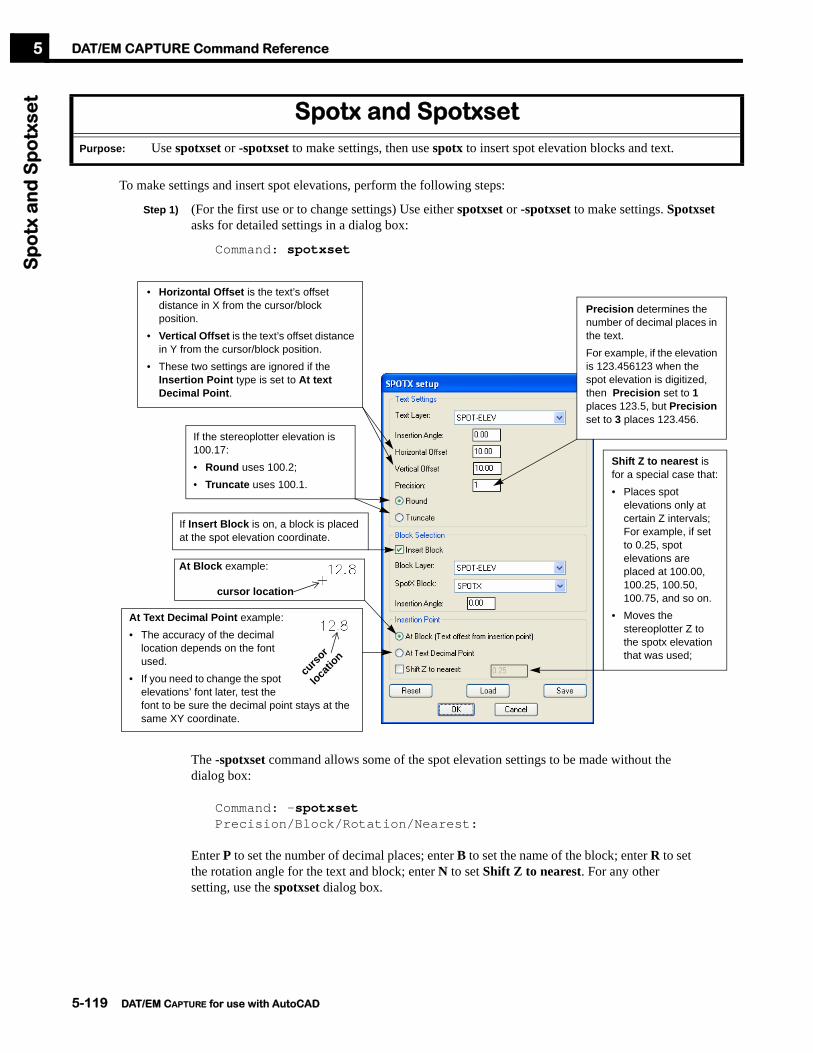
DAT/EM CAPTURE Command ReferenceS
po
tx a
nd
Sp
otx
set
5
To make settings and insert spot elevations, perform the following steps:
Step 1) (For the first use or to change settings) Use either spotxset or -spotxset to make settings. Spotxset asks for detailed settings in a dialog box:
Command: spotxset
The -spotxset command allows some of the spot elevation settings to be made without the dialog box:
Command: -spotxsetPrecision/Block/Rotation/Nearest:
Enter P to set the number of decimal places; enter B to set the name of the block; enter R to set the rotation angle for the text and block; enter N to set Shift Z to nearest. For any other setting, use the spotxset dialog box.
Spotx and SpotxsetPurpose: Use spotxset or -spotxset to make settings, then use spotx to insert spot elevation blocks and text.
If Insert Block is on, a block is placed at the spot elevation coordinate.
At Block example:
At Text Decimal Point example:• The accuracy of the decimal
location depends on the font used.
• If you need to change the spot elevations’ font later, test the font to be sure the decimal point stays at the same XY coordinate.
curso
r
locatio
n
If the stereoplotter elevation is 100.17:• Round uses 100.2;• Truncate uses 100.1.
cursor location
Shift Z to nearest is for a special case that:• Places spot
elevations only at certain Z intervals; For example, if set to 0.25, spot elevations are placed at 100.00, 100.25, 100.50, 100.75, and so on.
• Moves the stereoplotter Z to the spotx elevation that was used;
• Horizontal Offset is the text’s offset distance in X from the cursor/block position.
• Vertical Offset is the text’s offset distance in Y from the cursor/block position.
• These two settings are ignored if the Insertion Point type is set to At text Decimal Point.
Precision determines the number of decimal places in the text.For example, if the elevation is 123.456123 when the spot elevation is digitized, then Precision set to 1 places 123.5, but Precision set to 3 places 123.456.
5-119 DAT/EM CAPTURE for use with AutoCAD

DAT/EM CAPTURE Command ReferenceS
po
tx a
nd
Sp
otx
set
5
Step 2) Place spot elevations with the spotx command:
Command: spotxInsert point:
Step 3) Position the stereoplotter’s floating mark on the ground at the desired location. Digitize the point to place the spot elevation.
Step 4) Repeat Step 3 to position and digitize more spot elevations.
Step 5) When finished, press <Enter> at the “Insert point” prompt to end the command.
5-120 DAT/EM CAPTURE for use with AutoCAD

DAT/EM CAPTURE Command ReferenceS
qu
are
5
The square command squares the sides of an existing polyline object. It is especially useful for man-made objects such as buildings.
To use the square command, perform the following steps:
Step 1) Start the square command:
Command: squareXY Tolerance angle (20.0) degrees 0..45/<Enter>:
Step 2) Enter a new building squaring tolerance angle or press <Enter> to accept the default value. For example, to set the tolerance angle to 25 degrees,
XY Tolerance angle (20.0) degrees 0..45/<Enter>: 25XY Tolerance set to: 25Select objects to square
Step 3) To the “Select objects to square” prompt, select one or more existing polyline objects such as buildings. When finished selecting objects, press <Enter>. All of the objects will be squared according to the XY tolerance angle.
Square squares building sides according to the currently set XY Tolerance angle. This tolerance angle works in the same way as the angle used in Psqr. For more information about the tolerance angle, see page 5-102.
SquarePurpose: Squares the sides of existing polyline objects. Especially useful for existing buildings.
square
Existing polyline object Squared polyline
5-121 DAT/EM CAPTURE for use with AutoCAD

DAT/EM CAPTURE Command ReferenceS
tair
s5
To automatically draw a stairway, activate the stairs dialog box:
Command: stairs
• Attached 2D attaches the stairway at right angles to a previously digitized building (or to a straight segment of any polyline or line). The stairway is drawn with 2D polylines at the elevation of the first selected point.
• Attached 3D is the same as Attached 2D, except it uses 3D polylines, interpolating elevations based on the two selected corner points.
Points digitized with Stairs Attached 2D and Stairs Attached 3D
StairsPurpose: To draw stairways with options for elevation, landings, and aligning to buildings.
Point 1:Stairs corner on building line
Point 2:Diagonal stair corner
Point 3:Tread width (may be digitized or typed in ground units)
5-122 DAT/EM CAPTURE for use with AutoCAD

DAT/EM CAPTURE Command ReferenceS
tair
s5
• Free 2D draws a free-standing stairway using 2D polylines.
• Free 3D draws a free-standing stairway using 3D polylines.
Points digitized with Stairs Free 2D and Stairs Free 3D
• Landing 2D draws a stairway and landing attached at right angles to a building (or to a straight segment of any polyline or line).
• Landing 3D is the same as Landing 2D, except is uses 3D polylines, interpolating elevations based on the two selected corner points.
Points digitized with Stairs Landing 2D and Stairs Landing 3D
Point 1:First stair corner
Point 2:Diagonal stair corner
Point 4:Tread width (may be digitized or typed in ground units)
Point 3:Direction of the first stair
Point 2:Diagonal stair corner
Point 3:Tread width (may be digitized or typed in ground units)
Point 4:Point on the first landing tread (Select a point near the edge of the landing away from the building)
Point 1:Stairs corner on building line
5-123 DAT/EM CAPTURE for use with AutoCAD

DAT/EM CAPTURE Command ReferenceU
nro
tate
scre
en
5
The unrotatescreen command removes the rotation caused when the datemrotate command was used:
Command: unrotatescreen
The drawing regenerates and the rotation is set back to zero.
UnrotatescreenPurpose: To remove the rotation caused earlier by the Datemrotate command.
5-124 DAT/EM CAPTURE for use with AutoCAD

DAT/EM CAPTURE Command ReferenceW
allf
en
ce
5
Before starting any block patterning command, perform the following:
• Set the layer for the new objects.
• Use the setup command to verify the Block scale factor and Block rotation angle and select the desired Planimetric Patterning setting.
To insert wall and fence ticks alternately on the most recently drawn 2D or 3D polyline, choose Wall Fence on the keypad overlay or menu diagram. Or enter the wallfence command:
Command: wallfenceSelect objects <Last>:
Choose one or more 2D or 3D slope polylines or enter L to select the most recently digitized object. The computer then prompts:
(T)oggle side/(B)lock scale=#/(P)attern dist=# <Enter>:
The blocks appear visually along the polyline, but are not permanent objects until <Enter> is pressed. Several options may be changed before the blocks are actually inserted:
• To instantly change the direction of the blocks, enter T.
• To change the block size, enter B and set a new scale.
• To change the block pattern spacing, enter P and set the new spacing in ground units.
• When the blocks are correct, press <Enter> to accept them.
The file is searched for the block called WALLTICKR, WALLTICKL or FENCTICK. If the blocks do not already exist, they are created. Then the blocks are inserted at intervals along each selected polyline.
WallfencePurpose: To insert wall tick and fence tick blocks alternately along 2D or 3D polylines.
All blocks inserted at the same elevation!If on (checked), all the blocks will be inserted as follows:•For 2D polylines: at the polyline’s Z•For 3D polylines: at Z=0 and evenly spaced in the (X,Y) plane.
Blocks inserted at the polyline elevation.If off (not checked), the blocks will be inserted at the polyline Z. On 3D polylines, the elevation will be interpolated along the polyline segment.
(from the setup box)
5-125 DAT/EM CAPTURE for use with AutoCAD

DAT/EM CAPTURE Command ReferenceX
sec
t5
The xsect command creates cross sections along a road center line, then allows the user to collect coordinates along the cross sections. On analytical or digital stereoplotters with move capabilities, the stereoplotter is driven automatically to the sampling locations.
To create a cross section project, perform the following steps:
Step 1) Draw a polyline along the center of the road or along the project edge. The polyline does not need to run exactly along the center of a feature, but it will always be referred to as the center line in this text. The polyline may contain arc segments.
Step 2) Start the command and select c for Create. A dialog box appears asking for project values.
Command: xsectCreate/Import/Add/Delete/Edit/Xsectmode/Quit: c
Step 3) After filling out the project values and selecting OK, a prompt appears in the AutoCAD command window:
Select a polyline <Last>:
Select the center line polyline.
XsectPurpose: To create a cross section project and collect (X,Y,Z) data along the cross sections.
Sample center line with polyline containing arcs.
Enter a project name or browse for an existing project.
Enter project specifications
Select OK to continue
5-126 DAT/EM CAPTURE for use with AutoCAD

DAT/EM CAPTURE Command ReferenceX
sec
t5
Step 4) After selecting the center line, the xsect menu reappears. A file now exists that contains the calculated cross section locations. The next step is to import the cross sections graphically. Select i to Import the cross sections.
Create/Import/Add/Delete/Edit/Xsectmode/Quit: i
Select the project to import and the layer to contain the cross sections and their labels.
When OK is selected, the cross sections are inserted into the drawing.
Step 5) After importing the cross sections, the xsect menu returns. If desired, add break lines using Add:
Create/Import/Add/Delete/Edit/Xsectmode/Quit: a
When OK accepts the box, follow the prompts to select the center line and specify the insertion point on the center line:
Select a polyline <Last>:Select insertion point on the polyline:
The new cross sections are added to both the project file and the drawing file.
Sample center line with cross sections imported.
Fill out information that will apply only to the new break line.
Break lines added.
5-127 DAT/EM CAPTURE for use with AutoCAD

DAT/EM CAPTURE Command ReferenceX
sec
t5
Step 6) If desired, delete any unwanted cross section lines using Delete:
Create/Import/Add/Delete/Edit/Xsectmode/Quit: d
When OK accepts the box, follow the prompts to select the center line and specify one or more cross sections to be deleted:
Select a polyline <Last>:Select cross sections to be deleted:
Notice the text from the cross sections remains in the drawing file. Erase the text if desired. It is not a part of the project file, and it will not appear if the project is re-inserted.
Step 7) If desired, edit any cross section lines using Edit:
Create/Import/Add/Delete/Edit/Xsectmode/Quit: e
When OK accepts the box, follow the prompts to select the center line and specify the cross section to be edited:
Select a polyline <Last>:Select section to be edited:
Select the cross section. The changes take place in both the project file and the drawing file.
Select the project name.
Cross sections deleted.
Select the project name.
Enter information that will apply only to the selected cross section.
Cross section edited.
5-128 DAT/EM CAPTURE for use with AutoCAD

DAT/EM CAPTURE Command ReferenceX
sec
t5
Step 8) When the project file contains all the necessary cross sections, coordinate data may be digitized using the cross section mode, Xsectmode:
Create/Import/Add/Delete/Edit/Xsectmode/Quit: x
When OK accepts the settings box, the starting cross section may need to be selected, then the cross section mode prompt appears:
Skip/Back increment/Undo/skip Xsection/Finish (S/B/U/X/F) <pick>:
When a point is digitized, the specified block and text will be inserted.
To remove the most recently digitized point and move back to that location, use the Undo option.
On analytical or digital stereoplotters with move capabilities, use Skip, Back, and skip Xsection to skip the current increment point, move back to the last increment or cross section, and skip forward to the next cross section.
When finished digitizing, use the Finish option.
Select the project name.
Select movement and digitizing preferences.
• Check elevation works with Xsect Z interval to alert the user if the elevation has changed too much since the last digitized point.
• Check X,Y distance works with Xsect XY interval to alert the user if the X,Y position has changed too much since the last digitized point.
• These alerts help the user digitize enough points and prevent “wild points” digitized by accident with the mouse.
• Incremental movement mode causes the analytical or digital stereoplotter to move by increments equal to the Xsect increment.
• Manual movement mode must be set for analog stereoplotters or any stereoplotter that doesn’t have computer-driven move capabilities.
• Lock movement mode will be highlighted if the stereoplotter is capable of axis-locked movement. The stereoplotter will only be able to move along the axis of the current cross section. Points are digitized anywhere along that cross section.
5-129 DAT/EM CAPTURE for use with AutoCAD

DAT/EM CAPTURE Command ReferenceX
sec
t5
Sample of one cross section digitized
Step 9) To resume digitizing after an interruption, start the command again and make sure Sample from beginning is turned off.
Command: xsectCreate/Import/Add/Delete/Edit/Xsectmode/Quit: x
Step 10) To output the data to an ASCII file, use the xyzout command shown on page 5-133.
To resume digitizing on a selected cross section, turn off Sample from beginning.
5-130 DAT/EM CAPTURE for use with AutoCAD

DAT/EM CAPTURE Command ReferenceX
yzin
5
The xyzin command inputs coordinate and object information as objects into an AutoCAD drawing file. To use the command, perform the following steps:
Step 1) Prepare an input file. The minimum requirements for this file are that it has X and Y coordinate components. It can be a simple list of coordinates such as:
-478.206 42.303 471.650-337.664 43.649 527.920-440.722 -62.040 470.010
Or it can have comments and object information fields such as block names, line start and end markers, or even fields that will be ignored, such as:
1 POLYLINE 76346.209 -115157.149 187.060 BOUNDARY1 POLYLINE 76166.269 -117074.058 188.451 BOUNDARY1 POLYLINE 77378.088 -117244.778 188.437 BOUNDARY1 POLYLINE 76346.209 -115157.149 187.060 BOUNDARY;This is a comment line. Ignore this line.2 POLYLINE 76605.172 -115936.256 188.451 BUILDING2 POLYLINE 76676.519 -116161.211 188.451 BUILDING2 POLYLINE 76942.286 -115990.789 188.451 BUILDING2 POLYLINE 76870.939 -115765.834 188.451 BUILDING2 POLYLINE 76605.172 -115936.256 188.451 BUILDING3 POLYLINE 77003.531 -115426.570 188.464 BUILDING3 POLYLINE 76904.501 -115535.066 188.464 BUILDING3 POLYLINE 77072.964 -115688.831 188.464 BUILDING3 POLYLINE 77171.994 -115580.335 188.464 BUILDING3 POLYLINE 77003.531 -115426.570 188.464 BUILDING4 BLOCK 76534.276 -116704.989 188.788 MISC-OBJECT5 BLOCK 77113.487 -115881.978 188.788 MISC-OBJECT6 BLOCK 77708.768 -116249.440 188.788 MISC-OBJECT7 POINT 77022.278 -116706.041 188.788 MASSPOINTS8 POINT 76449.207 -116265.696 188.788 MASSPOINTS
Step 2) If a boundary layer will be used, prepare one or more closed polylines on that layer. If this option is used, objects will be imported only they lie wholly or partially inside a boundary polyline. If they lie completely outside all boundary polylines, they will be ignored.
Step 3) Start the xyzin command and specify the input file:
Command: xyzin
Step 4) Make settings in the dialog box.
• The Load button retrieves any previously saved settings.
• The Reset button clears all settings.
• The Save button saves the current settings, which may then be retrieved later by Load.
XyzinPurpose: To import objects from coordinates in an ASCII text file.
5-131 DAT/EM CAPTURE for use with AutoCAD

DAT/EM CAPTURE Command ReferenceX
yzin
5
Step 5) Select OK to run the command and import the objects.
Enter the input file name or select Browse to help locate the file.
If desired, use Load to retrieve previously saved settings
Select the object types to be inserted. The settings needed depend on the Line Format choices.• The Type Identifier field is only active when Object
type is placed in Selected Fields below. Enter the exact object identification text as it appears in the ASCII file.
• The Layer fields are only active when Layer is not placed in Selected Fields below. This means that the layer will not be read from the input file, so you may choose the target layer for each checked object type.
• Block Name is only active when Block name is not specified in Selected Fields below. This means that the block name will not be read from the input file, so you may choose the target block.
If the ASCII file contains object type identifiers, layers, and/or block names, you may either use them from the file or override them using Skip in Selected Fields below. For example, if the input file contains POINTs, you may insert blocks instead by Skipping the word POINT in the file and checking only Block in Object Types. The coordinates are then forced to be inserted as the block you specify.
If the file has comments embedded in it, then check on Comment indicator and enter the characters that indicate a comment line.
Set delimiter to the character(s) that separate fields in the input file.
Highlight each field that exists in the input file, then click on the >> button to add it to the Selected Fields list. Or, highlight a field in the Selected Fields list and click on << to remove it from the list.• To ignore a field, add Skip to Selected Fields.• Skip may also be used to override object type
identifiers, layers, and/or block names that exist in the file, but that you don’t want to use. If any of these are skipped, you may specify the override values in the Type Id, Layer, and/or Block Name fields above.
Sort the Selected Fields list to match the field order of the input file. Highlight a field and click on the Up or Down button to move it into the correct order.
To import only those coordinates that are inside closed polylines, check on Boundary Layer and set its Layer. Closed boundary polyline(s) should already exist (see Step 2 above).
(Optional) Select Save to save the settings for later use by the Load button.
Select OK to run the command.
5-132 DAT/EM CAPTURE for use with AutoCAD

DAT/EM CAPTURE Command ReferenceX
yzo
ut
5
The xyzout command exports coordinate and object information from an AutoCAD drawing file to an ASCII text file. To use the command, perform the following steps:
Step 1) If objects will be exported if they are completely or partially inside a boundary, prepare one or more closed polyline boundaries on a unique layer.
Step 2) Start the xyzout command:
Command: xyzout
Step 3) Make settings in the dialog box.
• The Load button retrieves any previously saved settings.
• The Reset button clears all settings.
• The Save button saves the current settings, which may then be retrieved later by Load.
Step 4) Select OK to run the command. If Select objects interactively is checked on, a prompt will appear to select objects in the AutoCAD drawing (note that all selected objects will be exported, even if they do not meet the layer, search, or object type requirements). A prompt appears to select an output file name.
XyzoutPurpose: To export objects to an ASCII output file.
Choose a method of selecting objects to export:• Check on Layers to export only objects on selected
layers. Use the All>>, >>, <<, and <<All buttons to list the desired layers in the Selected Layers list.
• Or, check on Search inside closed polylines on layer to export objects that are completely or partially inside a closed boundary polyline. Set the layer of the boundary polyline(s).
• Or, check on Select objects interactively to select objects yourself. Note that this setting overrides any layer, search, or object type settings; everything you select will be exported.
Check on object types to export. If an object type in not checked, it will not be exported, even if it is on a selected layer and/or inside a boundary polyline.Exception: If Select objects interactively is on, all objects that you select will be exported, even if they do not meet the layer, search, or object type requirements.
Specify a File Format. Use the >> and << buttons to move the desired fields into the Selected Fields list. Click on fields and use the Up and Down buttons to sort the fields into the desired output order.
Set the Column Delimiter to the character(s) that should appear between fields in the output file.
Set the Decimal Precision values to the number of decimal places to export for the coordinate components.
5-133 DAT/EM CAPTURE for use with AutoCAD

DAT/EM CAPTURE Command ReferenceZ
che
ck5
The zcheck command gives information about points where polylines intersect in the (X,Y) plane. It is most useful for making sure elevation contours do not cross each other. Zcheck works with any combination of 2d, lightweight, and 3d polylines. To activate the dialog box, enter the zcheck command:
Command: zcheck
Make selections in the dialog box and choose the OK button. The specified block will be inserted at each (X,Y) intersection that matches the layer and elevation difference criteria. Text showing the elevation difference (not the block or polyline elevation) will be inserted next to the block
The acad.dwt template drawing supplied with DAT/EM CAPTURE contains a block called LEADER. This block is an arrow designed to use with zcheck. This block, or any block, may be used to mark intersections.
ZcheckPurpose: To mark the point of intersection and the elevation difference between polylines where they intersect in the
(X,Y) plane.
Z Tolerance:• To mark all (X,Y) intersections, use a Z
tolerance of 0 (zero) or less.• (X,Y) intersections will be marked only if
the Z difference between the polylines is greater than or equal to the Z tolerance.
• For example, if z tolerance is 10, only (X,Y) intersections with an elevation difference 10 or greater will be marked.
Scale is multiplied times the map scale (Setup) to produce the block and text size.
If on, text will be inserted showing the elevation difference at the point of (X,Y) intersection. It is not the elevation of the block or polylines.
5-134 DAT/EM CAPTURE for use with AutoCAD

DAT/EM CAPTURE Command ReferenceZ
mo
ve5
The zmove command directs the analytical or digital stereoplotter to move to a specified elevation. The stereoplotter must have computer-directed move abilities.
To activate zmove, choose the keypad or menu item, or enter,
Command: zmoveMove to elevation <default>:
Enter the elevation at the prompt. The analytical or digital stereoplotter immediately drives to the new elevation, but stays in the same X,Y location.
ZmovePurpose: (Analytical or digital stereoplotters with move capabilities only) Move the analytical or digital
stereoplotter to a user-specified elevation.
See also: Contourdown, Contourup, Datmove, Movebypick
5-135 DAT/EM CAPTURE for use with AutoCAD

DAT/EM CAPTURE Command Reference5
5-136 DAT/EM CAPTURE for use with AutoCAD

Chapter 6. CAPTURE CONTOUR 6
Chapter 6. CAPTURE CONTOUR
Contour generation with DAT/EM CAPTURE can be accomplished using the CAPTURE CONTOUR™ package, which uses the SCOP library software by INPHO GmbH. INPHO is one of DAT/EM’s GeoToolBox partners. To purchase CAPTURE CONTOUR, contact DAT/EM or INPHO. Each of the GeoToolBox companies may be accessed from the web at www.geotoolbox.com. Specific information about INPHO products may be viewed from www.inpho.de.
Activate the Contour Pull-Down Menu
If the Contour pull-down menu does not already appear in AutoCAD®, then add it now. Follow the instructions given in “Activate the DAT/EM Menu Group(s) - AutoCAD 2005 and Previous Versions” starting on page 3-4 or “Activate the DAT/EM Menu Group(s) - AutoCAD 2006 and Higher” starting on page 3-11.
Verify that the Contour pull-down menu appears in AutoCAD.
Export Morphological Data for MATCH-TThe morphexporter command exports AutoCAD morphological data objects such as break lines, form lines, and exclusion polygons into the binary INPHO MATCH-T .wnp file format. MATCH-T generates DTM points that may be used as input for CAPTURE CONTOUR. See “Morphexporter” on page 5-89.
DAT/EM’s DAT/EM CAPTURE SCOP Interface + INPHO’s SCOP Library = Contour generation within AutoCAD
Expected Result:The Contour pull-down menu appears in AutoCAD.
DAT/EM CAPTURE for use with AutoCAD 6-1
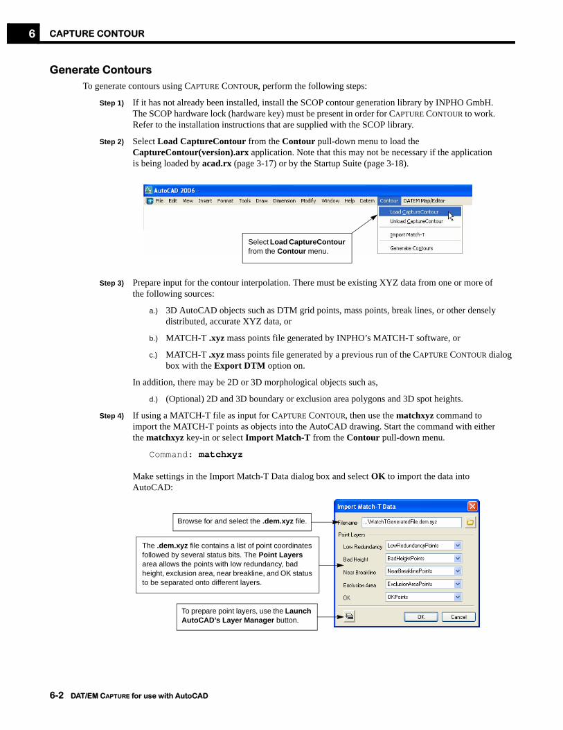
CAPTURE CONTOUR6
Generate ContoursTo generate contours using CAPTURE CONTOUR, perform the following steps:
Step 1) If it has not already been installed, install the SCOP contour generation library by INPHO GmbH. The SCOP hardware lock (hardware key) must be present in order for CAPTURE CONTOUR to work. Refer to the installation instructions that are supplied with the SCOP library.
Step 2) Select Load CaptureContour from the Contour pull-down menu to load the CaptureContour(version).arx application. Note that this may not be necessary if the application is being loaded by acad.rx (page 3-17) or by the Startup Suite (page 3-18).
Step 3) Prepare input for the contour interpolation. There must be existing XYZ data from one or more of
the following sources:
a.) 3D AutoCAD objects such as DTM grid points, mass points, break lines, or other densely distributed, accurate XYZ data, or
b.) MATCH-T .xyz mass points file generated by INPHO’s MATCH-T software, or
c.) MATCH-T .xyz mass points file generated by a previous run of the CAPTURE CONTOUR dialog box with the Export DTM option on.
In addition, there may be 2D or 3D morphological objects such as,
d.) (Optional) 2D and 3D boundary or exclusion area polygons and 3D spot heights.
Step 4) If using a MATCH-T file as input for CAPTURE CONTOUR, then use the matchxyz command to import the MATCH-T points as objects into the AutoCAD drawing. Start the command with either the matchxyz key-in or select Import Match-T from the Contour pull-down menu.
Command: matchxyz
Make settings in the Import Match-T Data dialog box and select OK to import the data into AutoCAD:
Select Load CaptureContour from the Contour menu.
The .dem.xyz file contains a list of point coordinates followed by several status bits. The Point Layers area allows the points with low redundancy, bad height, exclusion area, near breakline, and OK status to be separated onto different layers.
Browse for and select the .dem.xyz file.
To prepare point layers, use the Launch AutoCAD’s Layer Manager button.
6-2 DAT/EM CAPTURE for use with AutoCAD

CAPTURE CONTOUR 6
Now the AutoCAD drawing should contain a dense distribution of XYZ data objects within the area where contours are to be generated. There may also be boundaries, exclusion areas, and spot heights.
Step 5) Start the contour command. Either enter the contour key-in or select Generate Contours from the Contour pull-down menu.
Command: contour
There will be a pause as the software checks for the Inpho SCOP hardware lock. If it is not found, the top of the Capture Contour dialog box will show “Lock Not Found.” In this case, cancel the Capture Contour dialog and attach or troubleshoot the hardware lock.
Continue only if the hardware lock search is successful.
Sample mass points imported from a MATCH-T results file.
Select Generate Contours from the Contour menu.
If “Lock Not Found” is shown:• Cancel the Capture Contour dialog.• Attach the SCOP hardware lock or
troubleshoot hardware lock problems.• Run contour again.
DAT/EM CAPTURE for use with AutoCAD 6-3

CAPTURE CONTOUR6
Step 6) Start to make settings in the DAT/EM & Inpho’s Capture Contour dialog box. Choose whether input will come from entities on layers in the AutoCAD file or from a MATCH-T binary file:
There are two methods to choose input for CAPTURE CONTOUR: Either set Input layers or set a MATCH-T binary file name in Import DTM. The Import DTM field must be blank (or showing “Do not import DTM file”) in order to select Input layers.To use existing entities on AutoCAD layers:• Click where it says “Click to Select” or click on an existing list of layers.• Select one or more layers from each list. (Note that these layers should already
exist and there should already be objects on these layers.) If there is no input for that type, do not select any layers for that column.
• Repeat for each input type column.
There are two methods to choose input for CAPTURE CONTOUR: Either set Input layers or set a MATCH-T binary file name in Import DTM.To use a MATCH-T binary file:• Use the Import DTM browse button to select a
MATCH-T binary mass points file.• The file may have been created earlier by either
INPHO’s MATCH-T software or by an earlier run of CAPTURE CONTOUR with the Export DTM option on.
6-4 DAT/EM CAPTURE for use with AutoCAD

CAPTURE CONTOUR 6
Continue to make settings in the Capture Contour dialog box:
Select a contour interval for the resulting interpolated contours. The interval is in ground units.(Required) Select a contour Layer:
• This is the intermediate contour layer if an index contour layer is selected below.
• All contours will be on this layer if an index contour layer is not selected.
(Optional) Select an index contour Layer:• Select “No index contours” from the top of the list if index
contours will not be used.• To use index contours, select a layer and an index contour
Interval. The Interval should be an even multiple of the Interval above in the Contours area.
• For example, if Contours Interval is 5.00 and Index Contours Interval is 25.00, then intermediate contours will be placed at 95.0, 105.0, 110.0, 115.0, 120.0, and 130.0, while index contours will be placed at 100.0 and 125.0.
The Minimum Contour Area setting tests the area of closed contours (tops and depressions).• If the area of a closed contour is smaller than Minimum
Contour Area, then it does not insert that contour.• This prevents “tiny circles” from cluttering the contour set.• To disable this setting and insert all contours, set to 0.0 (zero).
To erase contours on a layer other than the currently set contours and index contours layers, set an Existing Contours layer before using the Erase Existing Contours button.• To disable this setting, select the
“(Delete existing contours)” message from the top of the layer list.
• This layer is used only by the Erase Existing Contours button.
DAT/EM CAPTURE for use with AutoCAD 6-5

CAPTURE CONTOUR6
Continue to make settings in the Capture Contour dialog box:
Step 7) Select OK to run the contour generation.
When OK is selected from the dialog box, the settings are used to send information to the SCOP library, which creates elevation contours. The contours are then imported into the AutoCAD file.
Step 8) View the resulting contours. If the contours seem incorrect in an area, then there may be mistakes or missing data in the mass points or morphological objects. In this case, improve the input data using any of the following methods:
• Use DTMedit (page 5-55) to edit points or morphological data;
• Add points. Note that if mass points have been added or edited, it may be useful to check on the Export DTM option on the Capture Contour dialog box.
• Add morphological data
• Edit morphological data
After editing the input data, run contour again. Use the Erase existing contours button to remove the old contours before generating the new ones.
Step 9) Repeat the review, edit, and run steps until the contours are acceptable.
Select a Smoothing setting for the resulting interpolated contours. The smoothest setting takes the longest to process.
If Grid method is selected, set a Grid Size.• If using a MATCH-T-generated input
points, enter the grid size or half the grid size that was used when running MATCH-T.
• If using a DTM grid digitized directly in AutoCAD, enter the distance between
If Export DTM is selected, all points currently in the AutoCAD file will be exported to an INPHO MATCH-T binary file. (This file may be used in a later run of CAPTURE CONTOUR or by INPHO software.
Contour may be generated based on a TIN (triangulated network) or from a grid.• If TIN is selected, choose an Optimize setting.• If Optimize is on, contours will be less jagged,
but processing time will increase. (TIN files are not saved for use with other applications.)
6-6 DAT/EM CAPTURE for use with AutoCAD

Chapter 7. Troubleshooting 7
Chapter 7. Troubleshooting
This chapter shows the most common problems encountered with DAT/EM CAPTURE™ and suggestions for solving them.
Problems During Startup
Symptom Suggestion
When DAT/EM software is run, one or more hardware lock messages appear:
Either the hardware lock is not installed properly, the hardware lock software driver was not installed, the hardware lock was not present in the port when DAT/EM software was updated, or the hardware lock is defective.
1. Follow the hardware lock installation instructions in the Summit Evolution Operation Manual or the DAT/EM installation supplement.
2. Check for a bad connection.
Contact DAT/EM support.
Cursor control will not transfer to the stereoplotter, and DAT/EM CAPTURE commands are “unknown.” For example,
Command: movebypickUnknown command "movebypick".Press F1 for help.
The DAT/EM application has not been loaded in AutoCAD. Select the “Load Capture” icon from the toolbar menus or select Capture and Load Capture from the Datem pull-down menu.
DAT/EM CAPTURE for use with AutoCAD 7-1

Troubleshooting7
AutoCAD Menus
Symptom Suggestion
There is no DAT/EM pull-down menu in AutoCAD. The Datem(version).mnu file is not configured correctly in AutoCAD. See “Activate the DAT/EM Menu Group(s) - AutoCAD 2005 and Previous Versions” on page 2-4 or “Activate the DAT/EM Menus - AutoCAD 2006 and Higher Versions” on page 2-8.
There is a Datem or DatemLite pull-down menu, but there are no DAT/EM toolbar menus.
The toolbar menus are not configured. See “Turn on DAT/EM Toolbars - AutoCAD 2005 and Previous Versions” on page 2-7 or “Activate the DAT/EM Menus - AutoCAD 2006 and Higher Versions” on page 2-8.
The toolbar menus are there, but they all look like question marks.
The \program Files\AutoCAD (version)\Datem\bmp folder is not referenced correctly, or was not referenced correctly at the time the menu was compiled. Set the Support File Search Path using the instructions in “Set the Support File Search Path and Pointing Device” on page 2-2. Then reload and recompile the menu file using the instructions in “Activate the DAT/EM Menu Group(s) - AutoCAD 2005 and Previous Versions” on page 2-4 or “Activate the DAT/EM Menus - AutoCAD 2006 and Higher Versions” on page 2-8.
The Datem or DatemLite menu is missing
7-2 DAT/EM CAPTURE for use with AutoCAD

Troubleshooting 7
Buttons and Switches
Symptom Suggestion
A stereoplotter button or switch is pressed, but either nothing happens or the wrong thing happens. (The plotter client is running and the DAT/EM application was loaded in the CAD software.)
The buttons and switches may not be set at all or they have been set to undesired functions.
1. Use the Buttons command to view the button settings. See “Buttons” on page 5-27.
2. Change the settings if necessary.
A button or switch is pressed, but nothing happens. The switch settings are verified to be correct using the Buttons command.
Button status is shown by the plotter client. With the plotter client running, press the switch. If the plotter client does not show that the switch has been activated, then there may be a hardware problem. Contact DAT/EM support.
DAT/EM CAPTURE for use with AutoCAD 7-3

Troubleshooting7
7-4 DAT/EM CAPTURE for use with AutoCAD

Appendix A. DAT/EM Technical Support A
Appendix A. DAT/EM Technical Support
For questions concerning this product, contact DAT/EM’s Support Department. You may be asked to purchase a software support agreement before support services are received.
DAT/EM Systems International8240 Sandlewood Place, Suite 101
Anchorage, Alaska 99507USA
Phone: (907) 522-3681Fax: (907) 522-3688
E-mail: [email protected]
General information is available on DAT/EM’s website at www.datem.com.
DAT/EM CAPTURE for use with AutoCAD A-1

DAT/EM Technical SupportA
This page intentionally left blank.
A-2 DAT/EM CAPTURE for use with AutoCAD

Index
Index
Numerics
2D2D polylines. See polylinesarcs 5-15 to 5-16digitizer mouse 3-1elevation contours 5-28
3D3D polylines. See polylinesarcs, simulated 5-13 to 5-14, 5-17 to 5-19digitizer 3-1offsets 5-11, 5-12, 5-41
3doffset 5-113doffsetmeasure 5-12
A
acad.dwt 4-1acad.rx
deactivating 2-12, 2-13 to 2-14editing 2-11 to 2-12loading files from 2-11 to 2-12
analog stereoplottercross sectioning with 5-100, 5-129installation 2-1
analytical stereoplottercross section move modes 5-129move commands
contour interval 5-37, 5-38control point 5-47user-specified point 5-47, 5-90Z elevation 5-135
point sampling commands 5-98, 5-126snap settings 5-46
analytical stereoplotter installation 2-1applications, loading automatically 2-11 to 2-13arc3d 5-13 to 5-14arcs
2D 5-15 to 5-163D simulation 5-13 to 5-14, 5-17 to 5-19
arx filesloading automatically 2-11 to 2-13loading manually 2-14
ASCII output from drawing objects 5-133autoarc2d 5-15 to 5-16autoarc3d 5-17 to 5-19
AutoCADacad.rx file
deactivating 2-12, 2-13 to 2-14editing 2-11 to 2-12loading files from 2-11 to 2-12
configuration Chapter 2layers 3-7Startup Suite 2-12 to 2-13support file path setup 2-2useful commands 3-7
autolist 5-20autolist(version).arx
command instructions 5-20loaded by acad.rx 2-11loaded by Startup Suite 2-13
B
base line angle for labelit 5-81block
defining 4-3elevation
editing 5-110, 5-111when creating 4-3
insertionexample 3-5how it works 3-4steps 3-4 to 3-5
layer 4-2patterning. See patterning with blocksrotation angle 5-21, 5-112rules
elevation rule 4-3layer rule 4-2size rule 4-2
samples list 3-4scale factor 5-112size 3-6, 4-2
blockrotate 5-21blockrotatelast 5-21blockrotate(version).arx
command instructions 5-21loaded by acad.rx 2-11loaded by Startup Suite 2-13
break lines. See breaklinesbreaklinefilter 5-22 to 5-23breaklinefilter(version).arx
command instructions 5-22loaded by acad.rx 2-11loaded by Startup Suite 2-13
DAT/EM CAPTURE for use with AutoCAD Index-i

Index
breaklinesadd to cross section project 5-127as morphological data for INPHO software 6-1, 6-2delete points and blocks near 5-22digitize with capt3d 3-3, 3-4, 5-30
brush 5-24BTICKL/R blocks 5-24building squaring
2D 5-101 to 5-1033D 5-104orthogonal building squaring 5-92, 5-94tolerance 5-113z tolerance 5-113
buildingframe 5-25button programming 5-27buttons 5-27
C
capt2dinstructions 5-28 to 5-29when to use 3-4
capt3dinstructions 5-30 to 5-31when to use 3-4
capture(version).arxloaded by acad.rx 2-11loaded by Startup Suite 2-13loading at AutoCAD startup 2-14loading methods 2-14
CAPTURE CONTOUR Chapter 6capturecontour(version).arx
how to run 6-2loaded by acad.rx 2-11loaded by Startup Suite 2-13
CaptureContour.cui 2-10changescale 5-32check3d 5-33check3dlast 5-33checklineelevation 5-33checklineelevationlast 5-33checklineelevation(version).arx
command instructions 5-33loaded by acad.rx 2-11loaded by Startup Suite 2-13
cleanup 5-34cleanup(version).arx
command instructions 5-34loaded by acad.rx 2-11loaded by Startup Suite 2-13
clipit command. See datclip
clipit(version).arxcommand instructions (datclip) 5-44loaded by acad.rx 2-11loaded by Startup Suite 2-13
clippoints 5-35close-range photogrammetry viewpoint 5-36closergview 5-36color of layers 3-7command 2-13command reference Chapter 5compatible hardware and software 1-2components 1-2configure AutoCAD 2-2 to 2-13connect polylines
editline 5-64joinit 5-79
contour interpolationbreaklines 5-30CAPTURE CONTOUR Chapter 6interp 5-75
contour intervalmove stereoplotter down in Z 5-37move stereoplotter up in Z 5-38rounding elevation to 3-4, 5-28set with setup 5-114
Contour(version).mnu 2-5contourdown 5-37contours. See elevation contourscontourup 5-38control points, inserting as blocks 5-84, 5-85converting drawing units 5-32coordinate shift 5-115cross sectioning with xsect 5-126 to 5-130crosscheck 5-39crossing polylines 5-39, 5-134culvert 5-40curb 5-41curbfilename 5-41curblast 5-41current pointing device 2-3cursor
control with mouse or stereoplotter 3-2missing 3-1seeing 3-1
customizeblocks 4-1 to 4-3button definitions 4-3, 5-27instructions Chapter 4layer scheme 4-1template drawing 4-1
Index-ii DAT/EM CAPTURE for use with AutoCAD

Index
D
datclip 2-11, 2-13, 5-44datem.com website A-1DAT/EM contact information Appendix ADatem(version).cui 2-9Datem(version).mnu 2-4datemrotate 5-45datemsnap 5-46datmove 5-47datpan 5-48default drawing 4-1, 4-3DEM (Digital Elevation Model). See DTMdep 5-49depression 5-50depression tick blocks 5-49, 5-50digital stereoplotter
cross section move modes 5-129move commands
contour interval 5-37, 5-38control point 5-47user-specified point 5-47, 5-90Z elevation 5-135
point sampling commands 5-98, 5-126snap settings 5-46
digital terrain modeling. See DTMdigitizing switch programming 5-27distribute DTM points 5-52DTM (Digital Terrain Modeling)
breaklinefilter 5-22 to 5-23combine point sets into one set 5-52digitizing method 5-31, 5-57, 5-98dtmdistributor 5-52dtmit 5-57 to 5-62edit points 5-55MATCH-T 6-2points and blocks next to breaklines 5-22profiledtm 5-98 to 5-100
dtmdistributor 5-52dtmdistributor(version).arx
loaded by acad.rx 2-11loaded by Startup Suite 2-13
dtmeditor 5-55 to 5-56dtmeditor(version).arx
loaded by acad.rx 2-11loaded by Startup Suite 2-13
dtmit 5-57 to 5-62dtmit(version).arx
command instructions 5-57 to 5-62loaded by acad.rx 2-11loaded by Startup Suite 2-13
dview twist AutoCAD command 5-45
E
edbox 5-63edge ties 3-8edit box tool 5-63editing
command list 5-4general information 3-8
editline 5-64 to 5-66elevation
contoursdigitizing 5-28 to 5-29interpolation
CAPTURE CONTOUR Chapter 6interp 5-75
use capt2d to digitize 3-4, 5-28 to 5-29editing Z in polyline 5-64, 5-110find Z range of lines/polylines 5-33labels 5-80 to 5-83, 5-119rounding 5-28 to 5-29
English unitsconvert to metric units 5-32map scale 5-112
export to a file with xyzout 5-133
F
fence 5-67fence and wall blocks 5-125fence ticks 5-67, 5-125FENCTICK block 5-67, 5-125foot pedals switch settings 5-27
G
GeoToolBox 6-1geotoolbox.com website 6-1grade of slope 5-86grail 5-68grid ticks and lines 5-69gridit 5-69ground control file 5-84, 5-85GTICKR/L block 5-68guard rail 5-68guiders for labelit 5-81gutters 5-41
DAT/EM CAPTURE for use with AutoCAD Index-iii

Index
I
importfile using xyzin 5-131MATCH-T file using matchxyz 6-2
incompatible hardware and software 1-2INPHO GmbH 6-1input. See importins 5-72, 5-73insert symbol function 5-72, 5-73inssetup 5-72, 5-73installation Chapter 2interp 5-75interpolate contours
CAPTURE CONTOUR Chapter 6interp 5-75
intersecting polylinesfinding and marking with zcheck 5-134finding with crosscheck 5-39
J
joindrawing edge ties 3-8polylines 5-64, 5-79roof levels 5-113
joinit 5-79
L
labelit 5-80 to 5-83layers 3-7lc 5-84lcf 5-85lineslope 5-86list improved by autolist(version).arx 5-20Load Applications Startup Suite 2-12 to 2-13load control
from file with lcf 5-85with lc 5-84
loading applications automatically 2-11 to 2-13lpat 5-87
M
map grids 5-69map scale setting 5-112MAP/EDITOR
filter uses 5-29, 5-31menu configuration
AutoCAD 2005 and previous 2-5AutoCAD 2006 and higher 2-10
used to edit 3-8MapEditor.cui 2-10
MapEditor(version).arxloaded by acad.rx 2-11loaded by Startup Suite 2-13
Maped(version).mnu 2-5MATCH-T
export morphological .wnp file 5-89, 6-1import .xyz file 6-2, 6-4
Measure(version).arx 2-11, 2-13measure(version).arx 5-25, 5-86, 5-88measureheight 5-88menu
pull-down menusContour 2-5, 2-10, 6-1Datem 2-4 to 2-7, 2-8 to 2-10DatemLite 2-4 to 2-7, 2-8 to 2-10Map/Editor 2-5, 2-10
toolbar menusAutoCAD 2005 and previous 2-7AutoCAD 2006 and higher 2-8 to 2-10
metric unitsconvert to English units 5-32map scale 5-112
modeone-shot for inserting blocks
instructions ?? to 3-5obsolete version 5-116when to use 3-5
streamcapt2d 3-4capt3d 3-4
two-shot for inserting blocksinstructions ?? to 3-5obsolete version 5-116when to use 3-6
morphexporter 5-89morphexporter(version).arx
command instructions 5-89loaded by acad.rx 2-13
movedown one contour interval 5-37to elevation 5-135to picked point 5-90up one contour interval 5-38
movebypick 5-90
Index-iv DAT/EM CAPTURE for use with AutoCAD

Index
O
offset polylines3doffset command 5-113doffsetmeasure command 5-12road command 5-107
one-shot mode for inserting blocks 3-4 to ??, 3-5, ?? to 3-5open a closed polyline 5-91openup 5-91opsqr2d 5-92opsqr3d
instructions 5-94tolerances 5-113
orient 5-97orient_only 5-97origin shift 5-115output
plotting 3-8to ASCII file with xyzout 5-133to MATCH-T .wnp file 5-89
P
pan view 5-48patterning with blocks
any block 5-87brush 5-24depression
automatic 5-50interactive 5-49
fence 5-67fence with wall 5-125guard rail 5-68lpat 5-87planimetric setting 5-87railroad ties 5-108slope ticks 5-118wall with fence 5-125
percent grade of slope 5-86planimetric patterning setting 5-87plotting 3-8plotting scale 5-112point elevation 5-110, 5-111pointing device, current 2-3
polylinesconnecting with joinit 5-79crossing 5-39, 5-134digitizing uses 3-3edit vertex Z 5-64editing 5-64intersections, finding 5-39, 5-134join 5-64join 2D and 3D 5-65offsetting 5-11, 5-12opening 5-91patterning with blocks
brush 5-24depression ticks
automatic 5-50interactive 5-49
fence 5-67fence with wall 5-125guard rail 5-68railroad ties 5-108, 5-109slope ticks 5-118user-specified block 5-87wall with fence 5-125
replace sections 5-64reverse vertex order 5-106
profiledtm 5-98 to 5-100programming buttons and switches 5-27psqr
instructions 5-101 to 5-103tolerances 5-113
psqr3dinstructions 5-104tolerances 5-113
R
railroaddouble line 5-108single line 5-109
ratio scale 5-112reference files as tie edges 3-8reinit AutoCAD command 5-97reverse 5-106reverse vertex order 5-106road 5-107road curbs and gutters 5-41, 5-107rotate blocks 5-21rr 5-108rr100 5-109
DAT/EM CAPTURE for use with AutoCAD Index-v

Index
S
screen rotationremove 5-124rotate to model 5-45
setblockz 5-111setobjectz 5-110setpointblockz 5-111setpointz 5-111setup 5-112 to 5-114shift 5-115shiftZ option of editline 5-64SHOT 5-116shot 5-116si commands 5-117si(version).arx 2-14
loaded by acad.rx 2-11loaded by Startup Suite 2-13
simulated arc for 3D polylines 5-66slope 5-118slope grade 5-86SLOPE_TICKR/L block 5-118slopetick 5-118software updates from DAT/EM support A-1spline
angle 5-114maximum XY distance 5-114Z distance 5-114
spot elevations 5-119spotx 5-119spotxset 5-119square 5-121squaring existing objects 5-121stairs 5-122 to 5-123Startup Suite for Load Applications 2-12 to 2-13stream mode digitizing 3-4, 5-30street curbs and gutters 5-41, 5-107SUPER/IMPOSITION commands 5-117support contact information Appendix Aswitch programming 5-27symbol
example list 3-4factor 3-6insertion 5-116insertion example 3-5See also block
T
technical support Appendix Atemplate drawing file 4-1, 4-3text scale factor 3-6, 5-112three-dimensional
3D polylines. See polylines 3-4digitizer 3-1offsets 5-11, 5-12, 5-41simulated arcs 5-13 to 5-14, 5-17 to 5-19
ticksbrush 5-24depression
automatic 5-50interactive 5-49
fence 5-67fence with wall 5-125guard rail 5-68pattern with any block 5-87railroad tie blocks 5-108, 5-109slope blocks 5-118wall with fence 5-125
tie edges 3-8tinpolygons. See buildingframetoolbar menus
AutoCAD 2005 and previous 2-7AutoCAD 2006 and higher 2-8 to 2-10
transparent view pan 5-48two-dimensional
2D polylines. See polylinesarcs 5-15 to 5-16digitizer mouse 3-1
two-shot mode for inserting blocks 3-5, 3-6
U
unitsconverting drawing 5-32English 5-112metric 5-112
unrotatescreen 5-124updates from DAT/EM support A-1
V
versions of software 1-2vertex order, reversing 5-106view
pan 5-48rotation
angle of model 5-45removing 5-124
Index-vi DAT/EM CAPTURE for use with AutoCAD

Index
W
wall and fence blocks 5-125WALL_TICKR/L blocks 5-125wallfence 5-125websites
www.datem.com A-1www.geotoolbox.com 6-1
Wintab Compatible Digitizer 2-3wnp file for MATCH-T 5-89www.datem.com A-1www.geotoolbox.com 6-1
X
X and Y coordinatesmoving to 5-46, 5-90of control points 5-84, 5-85snapping to 5-46
xref for edge ties 3-8xsect 5-126 to 5-130xy file 5-99xyzin 5-131xyzout 5-133
Z
Z coordinateediting Z in polyline 5-64, 5-110moving to 5-46, 5-135snapping to 5-46
Z range of lines/polylines 5-33zcheck 5-134zmove 5-135
DAT/EM CAPTURE for use with AutoCAD Index-vii