day 2: gregory e. peterson, senior technology specialist ... · pdf file4/15/2015 assessing...
TRANSCRIPT

4/15/2015
Assessing the Potential of Direct Metal Laser Sintering (DMLS)
To Reduce The Cost Of Vehicle Components
April 15, 2015
2nd Global Lightweight Materials Manufacturing Summit

4/15/2015
Agenda
1. What is DMLS?
2. Technology Overview: Assessing the Maturity Level Of DMLS
3. DMLS vs. Traditional Manufacturing Methods
4. Cost Assessment
5. Market Opportunities
6. Key Areas Requiring Technology Advances to Meet Automotive Needs
7. Acknowledgements
4/15/2015
1. What is DMLS?

1. 3D Printing History
http://3dprintingindustry.com/3d-printing-basics-free-beginners-guide/history/
• First patent application: 1980
• First patent: 1986
• EOS sold first “Stereos” system: 1990
• 1st <$10,000 system (3D Systems): 2007
• 1st commercially available 3D printer:
2009
• Alternative 3D printing processes
introduced at entry level: 2012
• DMLS parts go into production turbine
engines: 2015

1.0 Additive Manufacturing Technologies
Source: Linear Mold & Engineering, Inc., EOS.
Direct Metal Laser Sintering* (DMLS) Selective Laser Melting (SLM) Stereo Lithography (SLA) Selective Laser Sintering (SLS)
*Sintering is a process which heats a material to just below its boiling point
1.1 DMLS vs. SLS
Source: Linear Mold & Engineering, Inc., EOS.
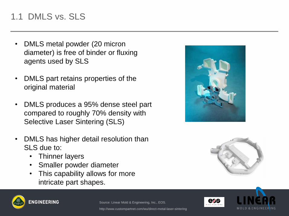
• DMLS metal powder (20 micron
diameter) is free of binder or fluxing
agents used by SLS
• DMLS part retains properties of the
original material
• DMLS produces a 95% dense steel part
compared to roughly 70% density with
Selective Laser Sintering (SLS)
• DMLS has higher detail resolution than
SLS due to:
• Thinner layers
• Smaller powder diameter
• This capability allows for more
intricate part shapes.
http://www.custompartnet.com/wu/direct-metal-laser-sintering

1.2 3D Metal Printing – Typical Hardware & Materials
• EOS M270s
• Materials Available:
• 15-5/17-4/316 Stainless Steels
• Cobalt Chrome (CoCr)
• Inconel 625/718
• Maraging Steel (MS1)
• EOS M280
• Materials Available:
• 15-5/17-4/316 Stainless Steels
• Aluminum (AlSi10Mg)
• Cobalt Chrome
• Inconel 625/718
• Maraging Steel (MS1)
• Titanium (Ti64)
• SLM 280
• Materials Currently Available:• Aluminum (AlSi10Mg)
• Titanium (Ti 64)
Source: Linear Mold & Engineering, Inc.

1.3 3D Metal Printing Process
Source: Linear Mold & Engineering, Inc.
• Metal powders are fused
together by a laser, creating
99.9% full melt
• Part built layer-by-layer
• Created quickly with no
tooling, straight from CAD
models
• Created with high accuracy,
detailed resolution, and
excellent mechanical
properties

1.4 Industries and Markets
• Aerospace
• Automotive
• Aircraft Engine Development
• Housewares
• Injection Mold Tool Inserts
• Medical
• Military
• Sporting Goods
Source: Linear Mold & Engineering, Inc.
Source: Linear Mold & Engineering, Inc.

- Net-shape metal parts created directly in
one step. No binder removal, and
generally no post-machining
- Outstanding geometric flexibility: free-
forms, deep slots and curved
blades/channels.
- Compatible with other processes. Parts
can be milled, drilled, welded, coated, etc.
- Rapid turn around time
- Accurate (+/- .002”)
- Excellent surface quality
- Wide array of materials
1.5 DMLS Benefits
Source: Linear Mold & Engineering, Inc.

1.6 DMLS Material Options & Storage Requirements
• Aluminum- light-weight, good thermal and dynamic properties
• Cobalt Chrome- excellent corrosion and temperature resistance
• Inconel 625 & 718- high tensile, fatigue and rupture strength
• Maraging Steel- superior toughness and strength
• Stainless Steels- excellent ductility and high corrosion resistance
• Titanium- low specific weight and biocompatibility
Source: Linear Mold & Engineering, Inc.
• Pre-conditioning:- powders stored in inert gas (Nitrogen or Argon)
- powders stored in low humidity (typically <15% relative
humidity)

4/15/2015
1.7 DMLS – Current Technology Overview
• Lasers: single, dual, twin
• Single: one laser per machine
• Dual (sequential): low power for thin outer shell, high power for filling
• Twin (simultaneous): make multiple parts simultaneously
• Challenge: beam overlap co-ordination for creating a single large part
• Laser power: 400 watts to 1,000 watts;
• EOS and SLM machines are both 220 volt AC, with 40 to 80 full load amperage
• Typical bed size: 8” x 8” x 8” EOS 270, 8” x 8” x 11” EOS 280, SLM 11” x 11” x 14”
• EOS 400: 400 mm x 400 mm (15.8” x 15.8”)
.
Source: Linear Mold & Engineering, Inc., EOS.

4/15/2015
1.8 DMLS – Typical Manufacturing Cost Considerations
• Machine cost/hr: typically $90/hr. to $140/hr.
• Additional related costs:
• HIPping (hot isostatic pressing)
• Eliminates porosity
• Restores part to 100% theoretical density
• Improves mechanical properties
• Heat treating
• 3D scanning
• X-ray
• CT scan
• Other
• Note: substantial cost/part reductions are achieved by running large “batches” vs.
individual part runs:
• Heat treat process: $400;
• cost for 1 part: $400/part;
• cost for a batch of 40 parts: $10/part
.
Source: Linear Mold & Engineering, Inc., .
http://www.pressuretechnology.com/about-hip.php

4/15/2015
1.9 DMLS – Material Costs
• Metal costs are substantially higher than non-powder form materials, primarily due
to very precise sieve control (typically 20 micron to 40 micron particle size)
• Offsets for higher material cost/lb. include:
• High level of parts consolidation
• No tooling
• No post process assembly time
• No assembly fixtures required
• No joining process required
• Minimal post-processing finishing
• Precise tolerance control minimizes finishing/rework
• Material cost is a low % of the piece price, typically 8% to 15%, vs. plastic molding
where material costs are typically 50% of the piece price
.Source: Linear Mold & Engineering, Inc., EOS.

4/15/2015
1.10 DMLS – Part Build Speed
Source: Linear Mold & Engineering, Inc., .
• Speed of build is a function of:
• 1) layer thickness (typically 20 micron to 60 micron layer thickness)
• 2) number of lasers (1 laser or 2 (twin) laser)
• 3) vertical height of the build
• 4) weld area of the individual layers
• Build Examples:
• A 25 mm tall, 60 micron layer, small area part can be built in approximately 6
hours
• A solid rectangular block that is 10” x 10” x 25mm tall would take over 100
hours

4/15/2015
1.11 Summary Assessment of DMLS Manufacturing
• Material cost/lb. is much higher than current casting/extrusion/molding/stamping material
costs
• Offsetting factors:
• Optimized design
• No die lock constraints to compromise part design
• Idealized part function
• Reduced weight
• High level of tolerance control
• Minimizes or eliminates post process machining
• No tooling costs
• Fully functional parts built with short lead times
• High level of parts integration
• Component combining 18 parts into 1 is in production
• No secondary fixturing
• Eliminates the need for joining operations
• No joining cost
• No parent material degradation
• No post-weld heat treatment

4/15/2015
2. Technology Overview:
Assessing the Maturity Level Of DMLS

4/15/2015
2. DMLS vs. Gartner Hype Cycle
.
http://search.tb.ask.com/search/AJimage.jhtml?searchfor=hype+curve&p2=%5EY6%5Exdm003
%5EYYA%5Eus&n=780cbf3d&ss=sub&st=bar&ptb=37C591F3-A913-43AB-A9A5-
92A61AD8A5A2&si=CM-
s14ramMECFcRAMgodZ2wABw&tpr=sbt#./&imgsize=all&safeSearch=on&imgDetail=true?&_sui
d=142730605882005100673767306902
• Where is DMLS on the Gartner Hype Cycle?

4/15/2015
2.1 Gartner Hype Cycle vs. Technology Adoption Timing
http://search.tb.ask.com/search/AJimage.jhtml?searchfor=technology+implementation+curve&p2
=%5EY6%5Exdm003%5EYYA%5Eus&n=780cbf3d&ss=sub&st=bar&ptb=37C591F3-A913-
43AB-A9A5-92A61AD8A5A2&si=CM-
s14ramMECFcRAMgodZ2wABw&tpr=sbt#./&imgsize=all&safeSearch=on&imgDetail=true

4/15/2015
2.2 Technology Adaptation Summary – Circa 2010
http://search.tb.ask.com/search/AJimage.jhtml?searchfor=technology+implementation+curve&p2
=%5EY6%5Exdm003%5EYYA%5Eus&n=780cbf3d&ss=sub&st=bar&ptb=37C591F3-A913-
43AB-A9A5-92A61AD8A5A2&si=CM-
s14ramMECFcRAMgodZ2wABw&tpr=sbt#./&imgsize=all&safeSearch=on&imgDetail=true?&_sui
d=142730574641706907364264136515
Current Status = ??

2.3 Current Applications – Dental Industry
http://www.scientistlive.com/content/25980
Bill Oremus, President of Rhode-Island based dental prosthetics
manufacturer, BEGO USA, predicts, "Our current product line
based on lost wax is probably going to be obsolete in ten to
fifteen years. The end of casting is approaching as the
introduction of layer-by-layer manufacturing to dentistry begins to
alter the landscape.”
The DMLS system runs automatically, quickly and economically,
providing a typical accuracy of ± 20 microns. Whereas a
traditional casting process can produce about 20 dental
frames per day, DMLS manufacturing is capable of up to 450
units of crowns and bridges in the same time period.
"The quality of the restorations is truly excellent, the surface
structure of the copings is much better, and the marginal integrity
is phenomenal. Moreover, we save cost and time.
“Lost wax accuracy: 50% – 60%; DMLS accuracy: 90 -95%”
DMLS Output
DMLS Quality
DMLS Ten to Fifteen Year Prognosis
Estimated DMLS Range

2.4 Current Applications – Aerospace Industry
Estimated Range
Pratt & Whitney prepares to deliver the first PurePower PW1500G
engines to Bombardier. This latest engine will feature what are
called “entry-into-service jet engine parts,” and they’re produced
using additive manufacturing techniques and space-age metals.
http://3dprint.com/55492/pratt-whitney-jet-engine-parts/
The project means dozens of parts produced using 3D
manufacturing processes made from titanium and nickel have been
flight-tested for use in Airbus and Bombardier aircraft entering
passenger service in the second half of 2015.
The list of parts includes brackets, oil nozzles, fuel-bypass
manifolds, mounts, fittings, and airfoils, and it’s the ability of
additive manufacturing techniques to make parts of nearly any shape
or geometry that makes it possible.
Lynn Gambill, the chief engineer for Manufacturing Engineering and
Global Services at Pratt & Whitney, says that during production tests,
the company has realized up to a 15 month lead-time savings and
up to 50 percent weight reduction in a single part when compared
to parts made with conventional manufacturing processes.

Material : 30% GF Nylon
(435 ° F operating temp)
Mold : 2 cavity injection mold,
P-20 material
Banana cores: P-20 material,
no cooling
Production : 350,000 parts/year
• Only 12 shots before severe
deformation in this area
• Banana core reaches
temperature of 300° F
• 100% scrap
Source: Linear Mold & Engineering, Inc.
2.5 Current Applications – Automotive Industry
Conformal Cooling Study
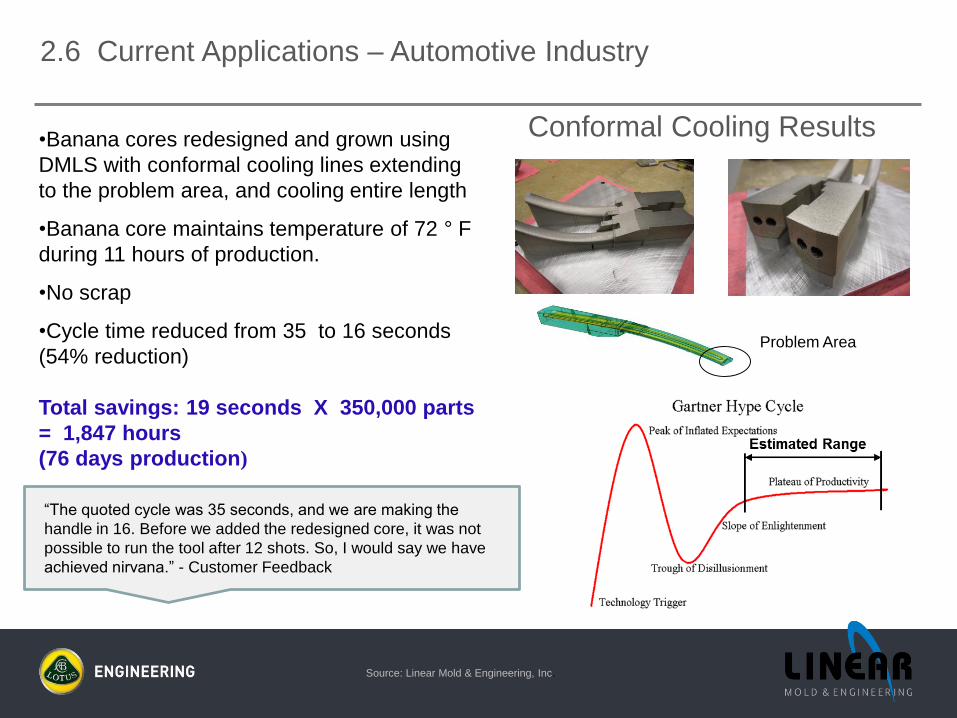
Conformal Cooling Results•Banana cores redesigned and grown using
DMLS with conformal cooling lines extending
to the problem area, and cooling entire length
•Banana core maintains temperature of 72 ° F
during 11 hours of production.
•No scrap
•Cycle time reduced from 35 to 16 seconds
(54% reduction)
Total savings: 19 seconds X 350,000 parts
= 1,847 hours
(76 days production)
Problem Area
“The quoted cycle was 35 seconds, and we are making the
handle in 16. Before we added the redesigned core, it was not
possible to run the tool after 12 shots. So, I would say we have
achieved nirvana.” - Customer Feedback
Source: Linear Mold & Engineering, Inc.
2.6 Current Applications – Automotive Industry

4/15/2015
2.7 DMLS vs. Moore’s Law
1. Electronic density doubles
about every two years
2. Processing speed doubles every
18* – 24 months
3. 40 year history of compliance
4. Moore’s Law not expected to
be sustainable much longer
http://en.wikipedia.org/wiki/Moore's_law#mediaviewer/File:Evolution_(34_365).jpg
* David House, Intel
Will DMLS follow Moore’s Law?
4/15/2015
2.8 Size, Cost and Performance Implications of Moore’s Law
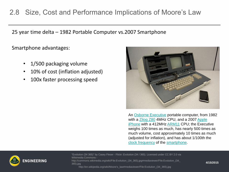
25 year time delta – 1982 Portable Computer vs.2007 Smartphone
Smartphone advantages:
• 1/500 packaging volume
• 10% of cost (inflation adjusted)
• 100x faster processing speed
http://en.wikipedia.org/wiki/Moore's_law#mediaviewer/File:Evolution_(34_365).jpg
"Evolution (34 365)" by Casey Fleser - Flickr: Evolution (34 / 365). Licensed under CC BY 2.0 via
Wikimedia Commons -
http://commons.wikimedia.org/wiki/File:Evolution_(34_365).jpg#mediaviewer/File:Evolution_(34_
365).jpg
An Osborne Executive portable computer, from 1982
with a Zilog Z80 4MHz CPU, and a 2007 Apple
iPhone with a 412MHz ARM11 CPU; the Executive
weighs 100 times as much, has nearly 500 times as
much volume, cost approximately 10 times as much
(adjusted for inflation), and has about 1/100th the
clock frequency of the smartphone.

4/15/2015
2.a Technology Overview:
Assessing the Maturity Level Of DMLS from
A NASA Perspective

Goddard
Evaluating a variety of instrument-development efforts and satellite components .
Langley
Developing/evaluating Electron Beam Freeform (EBF3) process.
Consists of: electron-beam gun, a dual-wire feed, and computer controls.
Near net shape metallic parts in hours, rather than days or weeks.
Kennedy
Investigating simulated regolith as feedstock for building 3-D habitats & other structures.
Ames
Exploring synthetic biology for the manufacturing of biological materials
Glenn
Evaluation of AM materials and AM subsystems.
Recently collaborated with Aerojet Rocketdyne to fabricate/evaluate an RL-10 rocket injector.
Marshall
Fabricate replacement components for the J-2X and RS-25 rocket engines.
Working with Made In Space to develop a 3-D printer to be use on the ISS (October 2014).
2.a.1 NASA: Diverse AM Research from Diverse Centers
28
Source: NASA Glenn.

29
First test of an AM rocket injector With As Fabricated Surface Finish:
• Reduced Part count from ~18 to 2
• Injector Performance better than previous design
Source: NASA Glenn.
2.a.2 Evaluating Propulsion Components and Developing
New AM Materials and AM Materials Test Databases
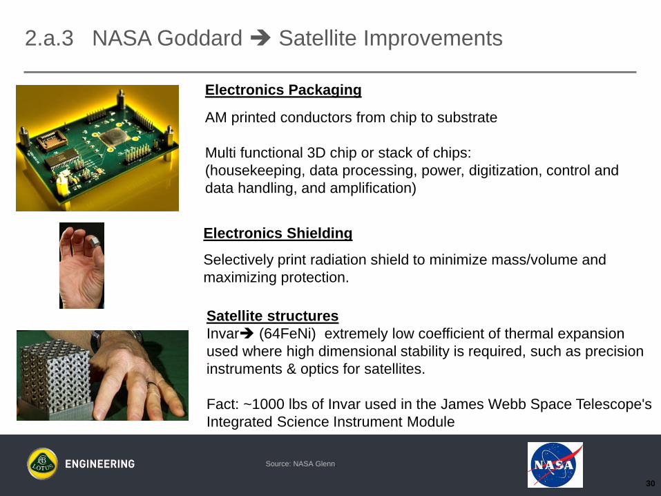
Electronics Packaging
AM printed conductors from chip to substrate
Multi functional 3D chip or stack of chips:
(housekeeping, data processing, power, digitization, control and
data handling, and amplification)
Electronics Shielding
Selectively print radiation shield to minimize mass/volume and
maximizing protection.
Satellite structures
Invar (64FeNi) extremely low coefficient of thermal expansion
used where high dimensional stability is required, such as precision
instruments & optics for satellites.
Fact: ~1000 lbs of Invar used in the James Webb Space Telescope's
Integrated Science Instrument Module
30
2.a.3 NASA Goddard Satellite Improvements
Source: NASA Glenn.

NON-PROPRIETARY
2.a.4 Additive Manufacturing Material Savings
• Manufacturing Processes:- Traditional (Subtractive) Manufacturing –final shape achieved by controlled material-removal.
- Additive Manufacturing (AM) – process of joining materials to make objects from 3D CAD data
Note: Calculation assumes Ti-6-4 composition, density 4.43g/cm3 (ASM standard)
Additive Manufacturing substantially decreases machining waste compared to traditional
methods resulting in meaningful decrease in cost and raw material weight.
Machining Waste Weighs 32X more than the Net Produced Part
EBM: Electron Beam Melting
EBF3: Electron Beam Free Form Fabrication
Volume: 1.47in3
Weight: 0.23 lbs
Volume: 1.81in3
Weight: 0.29lbs
Difference from CAD: 0.06 lbs
Difference from Cylinder: 7.35
lbs
Volume w/out base plate: 7.37in3
Weight: 1.18lbs
Difference from CAD: 0.95 lbs
Difference from Cylinder: 6.46 lbs
Volume: 47.71in3
Weight: 7.64lbs
Difference from CAD: 7.41 lbs
Material savings: 99.25%Net Part
Start with CAD
(Additive) EBM Part EBF3 PartStart with Block
(Subtractive)
Material Savings: 87.24% Cylinder
AM Comparison using ECLSS Urine Processor Assembly (UPA) Demister

2.a.5 NASA: AM Challenges for Metals
32
• Understanding of the anisotropy
• Aspect ratios of final part to grain size/layer
• Design methods to take advantage of anisotropy
• Increased testing for database generation
• Design processes on when to use AM and when to go conventional
• Relatively small complex parts
• Low production rates
• Potential anisotropy and internal surface finish will influence component life
• How thin can you go? What geometries are problems (i.e., >45o ramps will slump)?
• Understanding of residual stresses from the AM
• Manufacturing models/tools to take advantage of residual stresses
• To maintain tolerances
• To build in compressive stresses that are beneficial to component application
• Feedstock
• Handling: Contamination prevention and shelf life (especially for powders)
• Recyclability
• Learning curve for new materials systems
Source: NASA Glenn.
• Databases, databases, databases
• Need at least a b-basis database on each material system
• At least 30 repeats for each test condition/type

4/15/2015
3. DMLS vs. Traditional Manufacturing Methods

http://search.tb.ask.com/search/AJimage.jhtml?searchfor=stamping+tools&p2=%5EY6%5Exdm003%5EYYA%5E
us&n=780cbf3d&ss=sub&st=bar&ptb=37C591F3-A913-43AB-A9A5-92A61AD8A5A2&si=CM-
s14ramMECFcRAMgodZ2wABw&tpr=sbt#./&imgsize=all&safeSearch=on&imgDetail=true?&_suid=142798500236
305947133936495532
3. DMLS vs. Traditional Forming Technologies
• DMLS eliminates tooling
• DMLS minimizes/eliminates design compromises required by manufacturing process
.• Replaces forming options including:
• Stamping
• Casting
• Low pressure
• Die cast
• Investment cast
• Ablation cast
• High pressure
• Thixomolding
• Extrusion
• Impact
• Cold forming
• High pressure forming
• Molding
• Ultra high speed forming
• Other

4/15/2015
3.1 DMLS vs. Traditional Joining Processes
• DMLS component integration eliminates the need for a separate joining process
• DMLS eliminates the need to select a compromised method of joining materials
• DMLS eliminates the need for post-process fixturing & assembly
.

4/15/2015
4. Cost Assessment

4/15/2015
4. Key Cost Factors
Primary costs are a function of:
• Number of parts
• Design complexity
• Individual part weight
• Scrap material
• Material cost/lb.
• Tooling costs
• Joining costs
• Preparation
• Energy consumption
• Secondary machining/processing
• Fixturing costs
• Assembly costs
• Shipping costs
Secondary costs include:
• Time required to make tools/parts after design is complete
• Increased test time due to lack of prototype part fidelity to production parts
• Increased “time to market” for new vehicles
http://search.tb.ask.com/search/AJimage.jhtml?searchfor=DMLS+parts&p2=%5EY6%5Exdm003
%5EYYA%5Eus&n=780cbf3d&ss=sub&st=bar&ptb=37C591F3-A913-43AB-A9A5-
92A61AD8A5A2&si=CM-
s14ramMECFcRAMgodZ2wABw&tpr=sbt#./&imgsize=all&safeSearch=on&imgDetail=true?&_sui
d=1428984425057006542868210471753

4/15/2015
4.1 Cost Assessment
DMLS primary cost advantages include:
• Reduced number of parts through component integration
• Increased design complexity
• Optimized part weight
• Minimal scrap material.
• No tooling costs
• No joining costs
• No joining equipment required
• Low energy consumption for build process
• Minimal oversight of process
• Minimal or no secondary machining/processing
• No fixturing costs
• No assembly costs
• Reduced shipping costs P&W turbine engine fuel nozzle
• Reduced handling costs (18 parts into 1 part)
DMLS secondary cost advantages include:
• Immediate part turnaround following design completion
• Increased part fidelity to production for test parts
• Decreased “time to market” for new vehicles
4/15/2015
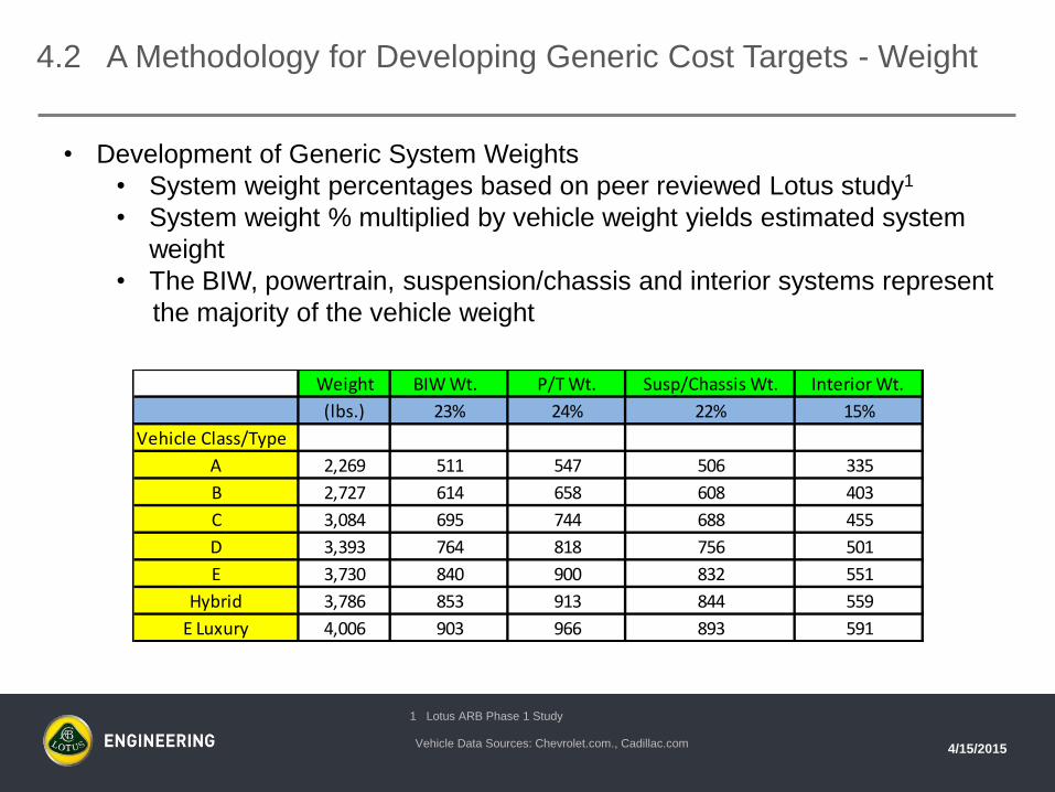
4.2 A Methodology for Developing Generic Cost Targets - Weight
• Development of Generic System Weights
• System weight percentages based on peer reviewed Lotus study1
• System weight % multiplied by vehicle weight yields estimated system
weight
• The BIW, powertrain, suspension/chassis and interior systems represent
the majority of the vehicle weight
1 Lotus ARB Phase 1 Study
Vehicle Data Sources: Chevrolet.com., Cadillac.com
Weight BIW Wt. P/T Wt. Susp/Chassis Wt. Interior Wt.
(lbs.) 23% 24% 22% 15%
Vehicle Class/Type
A 2,269 511 547 506 335
B 2,727 614 658 608 403
C 3,084 695 744 688 455
D 3,393 764 818 756 501
E 3,730 840 900 832 551
Hybrid 3,786 853 913 844 559
E Luxury 4,006 903 966 893 591

4/15/2015
4.3 A Methodology for Developing Generic Cost Targets - Cost
• Development of Generic System Costs
• System cost % breakout based on Lotus peer reviewed study1
• System % multiplied by vehicle RPE2 cost (A, B, C, etc. class)
2 RPE: Retail Price Equivalent = Invoice/1.46 - http://cfpub.epa.gov/si/si_public_record_report.cfm?dirEntryID=205147
Generic System Cost Chart1
1 Lotus ARB Phase 1 Study
Vehicle Data Sources: Chevrolet.com., Cadillac.com, http://www.car-buying-
strategies.com/dealer-invoice/
Invoice RPE BIW Cost P/T Cost Susp/Chassis Cost Interior Cost
18% 23% 13% 22%
Vehicle Class/Type
A $11,900 $8,151 $1,467 $1,875 $1,595 $1,793
B $13,880 $9,507 $1,711 $2,187 $1,852 $2,092
C $17,120 $11,726 $2,111 $2,697 $2,307 $2,580
D $21,670 $14,842 $2,672 $3,414 $2,920 $3,265
E $27,990 $19,171 $3,451 $4,409 $3,810 $4,218
Hybrid $33,345 $22,839 $4,111 $5,253 $4,465 $5,025
E Luxury $42,200 $28,904 $5,203 $6,648 $5,806 $6,359
*Estimated invoice

4/15/2015
4.4 A Methodology for Developing Generic Cost Targets – Cost/Lb.
• This approach allows prioritizing vehicle classes and systems based on highest
$/lb.
• Larger vehicles, e.g., E class, have greater $/lb. costs than smaller vehicles,
e.g., B class
• The interior system cost/lb. is 55% to 85% higher than the BIW, powertrain
and suspension/chassis systems
• The luxury class vehicle $/lb. is approximately 40% higher than a non-luxury
equivalent size vehicle
MSRP Invoice RPE Weight BIW $/lb. P/T $/lb. Susp/Chassis $/lb. Interior $/lb.
(lbs.)
Vehicle Class/Type
A $12,270 $11,900 $7,933 2,269 $2.79 $3.33 $3.15 $5.21
B $14,245 $13,880 $9,253 2,727 $2.71 $3.24 $3.05 $5.06
C $17,745 $17,120 $11,413 3,084 $2.96 $3.53 $3.36 $5.51
D $22,465 $21,670 $14,447 3,393 $3.40 $4.06 $3.86 $6.34
E $29,310 $27,990 $18,660 3,730 $4.00 $4.77 $4.58 $7.45
Hybrid* $34,345 $33,345 $22,230 3,786 $4.69 $5.60 $5.29 $8.75
E Luxury $44,660 $42,200 $28,133 4,006 $5.61 $6.70 $6.50 $10.46
*Estimated invoice
Vehicle Data Sources: Chevrolet.com., Cadillac.com, http://www.car-buying-
strategies.com/dealer-invoice/
1 RPE: Retail Price Equivalent = Invoice/1.46 - http://cfpub.epa.gov/si/si_public_record_report.cfm?dirEntryID=205147

4/15/2015
5. Market Opportunities
4/15/2015
5. Market Opportunities - Overview
• DMLS components must meet stringent performance, cost, mass, quality and
reliability standards
• DMLS parts have already demonstrated the ability to meet the above requirements
in the medical, automotive tooling and aerospace industries
• High volume automotive applications require substantial increases in output for
DMLS to be competitive
• DMLS parts need to be designed to maximize DMLS benefits for automotive
applications to reduce costs

4/15/2015
5. Assessing High Potential Areas For Implementing DMLS
• Vehicle Interiors
• Target areas with opportunities for high level of
component integration, e.g., seat structure
• Target complex structural parts, e.g., integrated air
bag/IP mounting structure
• Curved mini-heat exchangers for localized
heating/cooling
• Knee bolster structure with variable strength tuning
• Crash Energy Management
• Highly optimized lightweight local “crush cans”
• Powertrain
• Fuel & oil delivery system components
• Chassis/suspension
• Target complex lightweight components, e.g.,
steering knuckles, brake rotors
Source: Linear Mold & Engineering, Inc.

Integrated cooling channels help to reduce weight and increase performance
Source: ka.race.ing Karlsruhe
5.1 Lightweight Brake Rotor
Lattice structure brake rotor
Application
Conceptual break disk for formula SAE
student race car
Integrated cooling channels to reduce
weight and optimize cooling effect
Product details
Weight: 390 g
Material: Cobalt Chrome
Advantages
Reduced weight by 25%
Significant increase in performance due
to controlled cooling flow

4/15/2015
6. Key Areas Requiring Advances in DMLS Technology

4/15/2015
6. Technical Limitations – Current Technology
• In laser melting type machines, the speed of an individual laser is
limited by the mechanical movement of the mirrors that direct the
laser
• Build speed increases come from the addition of multiple
lasers.
• Relatively small plate sizes
• Larger plate sizes require additional lasers
• Plate sweep speed
• Larger plates could increase build time at current speeds
• Support structure
• Time consuming process for both build and post-build finishing
• High material costs ($/lb.)
• Typically small batches
• High level of filtration required
Picture Source: Linear Mold & Engineering, Inc., .

4/15/2015
6. Meeting Automotive Volume Requirements: Assessing DMLS
Readiness on The Gartner Hype Cycle
1 part/week
(current)
1 part/minute
(required )
Picture Source: Linear Mold & Engineering, Inc., .
4/15/2015
6.1 Future DMLS Enhancements – Beam Function
Source: Linear Mold & Engineering, Inc., .
• Replace mirror guided lasers with electron beams
• The Arcam EBM Q10 electron beam maintains several melt pools
simultaneously
• Advantage: Much faster response than a mirror guided laser
• Disadvantage: Cannot make intricate shapes.
• Used primarily to make titanium medical implants
• Increase power level
• Arcam EBM Q10 electron beam energy is 3,000 watts
• 3x to 7x more energy than typical laser
• Increase number of lasers/electron beams

Benefits:
• High energy efficiency and feedstock usage efficiency compatible with space-based operations
• Electron beam can be modulated to perform multiple operations (welding, deposition, heating,
surface modification, machining, etc.)
• Wire feedstock safely handled in reduced gravity
• Can process wide variety of metallic materials
Basics:
• Layer-additive process to build parts using CNC
techniques
• Electron beam melts pool on substrate, metal wire
added to build up part
• Successfully demonstrated in 0-g during parabolic
flight tests
• Demonstrating design and build of candidate
replacement part for finishing and testing in ground-
system test bed
• Developing S-basis allowables and modeling to predict
properties for certification
6.2 Langley Electron Beam FreeForm Fabrication (EBF3)

4/15/2015
6.3 Future DMLS Enhancements – Non-Beam Functions
Source: Linear Mold & Engineering, Inc., .
• Automated support structure removal
• The DMLM process builds a part that is constructed inside of a large
honeycombed metal support structure
• New technology for support structure removal is required to replace the labor
intensive process of removing the support structure
• Material processing
• Improve throughput for large batches
• Increase plate size
• Increase plate sweep speed
• Combine post-build processes into initial build
• HIPping
• Heat treat
Picture Source: GPI Prototype & Manufacturing Services, Inc., .

4/15/2015
6.4 Future DMLS Enhancements – Ideal Process
• One part/minute (10,000 parts/week) output for high volume automotive
• Precision electron beams or large array lasers
• Robotic removal of support structure using electron beam or lasers
• Performed on same platen or
• Transferred to a second machine as part of the process
• Very large bed sizes
• Discrete bed areas
• In-line HIPping process
• In-line large batch heat treating
• Large batch material pre-treatment
• Quick & efficient filtration
Separate
HIP
H.T.

7. Acknowledgements – Co-contributors
Mr. Bob Henderson
Additive Manufacturing Manager
Linear Mold & Engineering
12926 Stark Road
Livonia, MI 48150
53
Dr. Paul Bartolotta
NASA Glenn Research Center
21000 Brookpark Road, MS 49-8
Cleveland, Ohio 44135

CHINA
7th Floor, New Jinqiao Tower
No. 28 New Jinqiao Road, Pudong
Shanghai. PR CHINA 201206
Phone +86 (21) 5030 9990
MALAYSIA
Malaysia Sdn. Bhd. Lot G-5, Enterprise 3
Technology Park Malaysia
Lebuhraya Puchong-Sungai Besi
Bukit Jalil. 57000 Kuala Lumpur
Phone +60 (3) 8996 7172
Please reply to:
Job title:
Telephone:
Email:
Website: lotuscars.com/engineering
UNITED KINGDOM
Potash Lane
Hethel, Norwich
NR14 8EZ
Phone +44 (0) 1953 608423
USA
1254 N. Main Street
Ann Arbor
MI 48104
Phone +1 734 995 2544
Gregory E. Peterson
Senior Technical Specialist
248-508-0292