day one: deploying a secure wireless lan - data · pdf fileday one: deploying a secure...
TRANSCRIPT

Juniper Wireless Technologies
Build out a high-performing wireless
LAN, indoors, outdoors, and across
campuses, without compromising security
or manageability. Hello, mobility.
By Laura A. Phillips and Tim McCarthy
DAY ONe: DePLOYINg A SeCUre WIreLeSS LAN

Juniper Networks Books are singularly focused on network productivity and efficiency. Peruse the complete library at www.juniper.net/books.
Published by Juniper Networks Books
DAY ONE: DEPLOYING A SECURE WIRELESS LAN
The explosion of mobile device usage, from smartphones to iPads, has created a de-mand for mobility that is making the entire IT industry sit up and take notice. People want to work wherever they are, whenever they need to. And that means wireless LANs. Whether you need to replace legacy wi-fi systems or need to build out a new LAN, you need a secure system that doesn’t increase your workload.
Day One: Deploying a Secure Wireless LAN walks you through how to plan and deploy a simple wireless network step by step. You’ll be introduced to wireless basics, review some of the tools for wireless network planning, and then take part in the actual de-ployment configuration. It’s time to cut through the clutter and get this wireless solution done in a day.
IT’S DAY ONE AND YOU HAVE A JOB TO DO, SO LEARN HOW TO:
n Understand wireless networking basics.
n Understand wireless network planning and the tools and resources necessary to fine-tune your wireless plan.
n Console into a wireless controller and configure basic IP connectivity.
n Configure basic VLANs on the network.
n Configure local administration.
n Troubleshoot common issues on the wireless LAN to get operational.
n Upgrade the software on a WLC.
n Add wireless clients to your wireless LAN.
“This Day One book is a fabulous resource. It’s packed with everything you need to know to get
up and running on a secure Juniper wireless network in no time.”
Steve Troyer, VP, Product Line Management and Technical Marketing, Campus and Branch Business Unit, Juniper Networks, Inc.
ISBN 978-1936779482
9 781936 779482
5 1 2 0 0
07100152

Day One: Deploying a Secure Wireless LAN
By Laura A. Phillips and Tim McCarthy
Juniper Wireless Technologies
Chapter 1 : Learning Wireless Networking Basics . . . . . . . . . . . . . . . . . . . . . . . 7
Chapter 2 : Overview of Wireless Network Planning . . . . . . . . . . . . . . . . . . . .21
Chapter 3 : The Components of a Wireless LAN . . . . . . . . . . . . . . . . . . . . . . . 29
Chapter 4: Using the Quickstart Command . . . . . . . . . . . . . . . . . . . . . . . . . . . 37
Chapter 5: Additional Configurations for the Wireless LAN . . . . . . . . . . . . . 49
Chapter 6: Testing Connectivity on the Wireless LAN . . . . . . . . . . . . . . . . . . 55
Chapter 7: Troubleshooting Wireless Connectivity . . . . . . . . . . . . . . . . . . . . . 59

© 2012 by Juniper Networks, Inc. All rights reserved.
Juniper Networks, the Juniper Networks logo, Junos, NetScreen, and ScreenOS are registered trademarks of Juniper Networks, Inc. in the United States and other countries. Junose is a trademark of Juniper Networks, Inc. All other trademarks, service marks, registered trademarks, or registered service marks are the property of their respective owners.
Juniper Networks assumes no responsibility for any inaccuracies in this document. Juniper Networks reserves the right to change, modify, transfer, or otherwise revise this publication without notice. Products made or sold by Juniper Networks or components thereof might be covered by one or more of the following patents that are owned by or licensed to Juniper Networks: U.S. Patent Nos. 5,473,599, 5,905,725, 5,909,440, 6,192,051, 6,333,650, 6,359,479, 6,406,312, 6,429,706, 6,459,579, 6,493,347, 6,538,518, 6,538,899, 6,552,918, 6,567,902, 6,578,186, and 6,590,785.
Published by Juniper Networks BooksWriters: Laura A. Phillips, Tim McCarthy, and
Maya Devi SContributors: Carmen Kelling, Hannes Ter Linde,
Lance Carr, Sanjai Raut, Sudhaker VenkateshEditor in Chief: Patrick AmesCopyeditor and Proofing: Nancy KoerbelIllustration: Laura A. PhillipsJ-Net Community Management: Julie Wider
About the AuthorsLaura A. Phillips is a longtime writer of documentation for wireless products, beginning with a wireless firewall in 2002.
Tim McCarthy is a Technical Marketing Manager for the Juniper WL and Branch SRX product lines. Tim has been designing and deploying enterprise WLAN solutions for the past 10 years.
Authors' AcknowledgmentsDedicated to everyone in Juniper Networks Wireless LAN Services under Pankaj Malhotra and Steve Troyer. Thank you all for answering our queries and providing insightful information. A big thank you goes out to you all!
ISBN: 978-1-936779-48-2 (print)Printed in the USA by Vervante Corporation.
ISBN: 978-1-936779-49-9 (ebook)
Version History: v1 July 2012 2 3 4 5 6 7 8 9 10 #7100152-en
This book is available in a variety of formats at: www.juniper.net/dayone.
Send your suggestions, comments, and critiques by email to [email protected].
ii

Welcome to Day One
Day One books help you to quickly get started in a new topic with just the information that you need on day one. The Day One series covers the essentials with straightforward explanations, step-by-step instruc-tions, and practical examples that are easy to follow, while also provid-ing lots of references on where to learn more. A second series, This Week, which covers more advanced topics that might be presented in a week-long training session, is also available.
Both the Day One and This Week book series are available at:
� Download a free PDF edition at http://www.juniper.net/dayone.
� Get the eBook edition for iPhones and iPads from the iTunes Store. Search for Juniper Networks Books.
� Get the eBook edition for any device that runs the Kindle app (Android, Kindle, iPad, PC, or Mac) by opening your device's Kindle app and going to the Kindle Store. Search for Juniper Networks Books.
� Purchase the paper edition at either Vervante Corporation (www.vervante.com) or Amazon (www.amazon.com) for between $12-$28, depending on page length.
� Note that Nook, iPad, and various Android apps can also view PDF files.
� If your device or eBook app uses .epub files, but isn't an Apple product, open iTunes and download the .epub file from the iTunes Store. You can then drag and drop the file out of iTunes onto your desktop and sync with your .epub device.
What You Need to Know Before Reading This Book
Before reading this book, you should have a basic understanding of Mobility System Software, the wireless LAN controller operating system that operates Juniper’s wireless products. (Note that the Junos operating system is not yet ported to the product suite – the products became part of Juniper’s product portfolio with its acquisition of Trapeze Networks.)
� You should be able to navigate through a command line hierarchy.
� You need to understand basic networking principles including TCP/IP, DHCP, and wireless protocols.
iii

iv
� You need to have physically installed your wireless access points and controllers in the desired locations. This book assumes that you have a small- to medium-sized network, one WLC, and ten WLAs.
� If you don’t have a physical installation, you need to have a lab with the necessary access points and controllers so you can test and configure them before installing.
� You or your IT administrator needs to have assigned valid IP addresses for your network.
NOTE Wireless LAN Controller is a mouthful to say and is typically referred to as a WLC or just a controller. Wireless LAN Access Point is also a mouthful and is referred to as a WLA or just AP.
MORE? It is highly recommended that you become familiar with the Juniper Networks Mobility System Software Configuration Guide, and the Mobility System Software Command Reference, available at http://www.juniper.net/techpubs/.
After Reading This Book, You’ll Be Able To...
� Understand wireless networking basics.
� Understand wireless network planning and the tools and re-sources necessary to fine-tune your wireless plan.
� Console into a wireless controller and configure basic IP connec-tivity.
� Configure basic VLANs on the network.
� Configure local administration.
� Troubleshoot common issues on the wireless network to get operational.
� Upgrade the software on a WLC.
� Add wireless clients to your wireless network.

v
This Book’s Network Topology
This book uses a sample wireless deployment with one WLC880R and ten WLA532s that is simple enough for you to follow along, yet complex enough so that you can extrapolate your own deployment.
For the purposes of this book, you are the IT manager of ACME Roundtuit, a small manufacturing facility that wants to implement wireless technology and allow employees to access email, calendars, and Facebook (okay, maybe not Facebook), without being tethered to a desk. The company also wants to allow site visitors access to the wireless network by using a Web portal that permits users to log into the wireless network, but keeps sensitive corporate information secure by placing guest users in a separate secure VLAN.
You’ve determined that you’ll need two EX-series switches for PoE and DHCP to complement your existing SRX650. Your network topology looks like the diagram shown in Figure A.1.
WLA 532s
Radius/DHCP/DNS
WAN
Corporate Office
Floor 2
Floor 1
WLC 880R
172.24.111.2
172.24.111.110
SRX 650
172.24.111.1/24
EX
(PoE)
172.24.111.115
WLA 532s (PoE)75.126.225.99
EX (PoE)
EX (PoE)
EX (Aggregation)
VLAN - Corp
VLANs- Corp, Guest
Figure A.1 ACME Roundtuit Manufacturing Network Topology

vi
The IP addresses from Figure A.1 are used in the example configura-tion steps in this book. Also, you can see that there are two VLANs configured on the network with different access privileges.
In general, best practice recommends naming WLAs based on the location of the WLAs, as shown in Table A.1, where the naming convention used is a floor-department hybrid. It’s a naming scheme recommended by Juniper TAC and Professional Services, and aids when troubleshooting an access point (AP), as you can instantly know the location of the AP by the name.
Table A.1 Example Naming Convention for WLAs
Name Location Serial Number
FL1-ENG-Dev Engineering Dev -1st floor JB0211322859
FL1-MFG-Line1 MFG Line 1 – 1st Floor JB0211322860
FL1-MFG-FP MFG Final Product – 1st floor JB0211322861
FL1-S&R Shipping and Receiving 1st floor JB0211322862
FL1-RM Raw Materials - 1st Floor JB0211322863
FL2-EXEC Executive Offices – 2nd floor JB0211322864
FL2-ACCT Accounting/Finance – 2nd floor JB0211322865
FL2-R&D R&D – 2nd floor JB0211322866
FL2-Conf1 Baltic Conf Room – 2nd floor JB0211322867
FL2-Conf2 Adriatic Conf Room – 2nd floor JB0211322868

Chapter 1
Learning Wireless Networking Basics
Why Wireless Networking? . . . . . . . . . . . . . . . . . . . . . . . . . . . . . . . . . . . . . . . . . . . 8
Overview of Juniper’s Wireless Product Portfolio . . . . . . . . . . . . . . . . . . . . . . 16

8 DayOne:DeployingaSecureWirelessLAN
The explosion of mobile devices, from smartphones to iPads, has created a demand for on the go mobility for the IT industry. People are no longer content to sit in a cube in front of a PC when it is possible to work wherever they happen to be. Always connected is now a require-ment for most corporate networks and to meet that challenge you’ll have to understand some basics of wireless networking.
Why Wireless Networking?
Of course the obvious advantage to wireless networking technology is mobility! But another less obvious advantage is the flexibility of deployment in an existing LAN network. A number of wireless base stations (access points, or AP) are used to connect users to the LAN network, and fortunately, whether you are deploying 10 or 10,000 access points, the infrastructure is pretty much the same. Once the infrastructure is built, the wireless network must be configured to recognize and offer services to users on the network; adding users requires authentication and security policies.
Once you understand wireless networking basics and simple wireless network planning, you can then deploy a secure wireless network in your chosen environment, be it similar to ACME Roundtuit or your own circumstance. If you have an existing LAN network then you have a flexible deployment.
Let’s begin.
TheDynamicsofWirelessNetworks
It’s safe to say that once wired networks are installed, they’re pretty boring. They tend to do the same thing every day: direct network traffic over wires on the network. Yawn.
Because wireless networks are, well, wireless, they have a more open medium than wired ones. There is not a well-defined path consisting of a physical cable. It’s a radio link with encoding and modulation. Radio signals can be picked up and sent by anyone with a radio receiver, so anyone can intercept data on the network using devices readily available at your local “big box” store.
Radio waves also travel outside of the intended location and there is no abrupt physical boundary of the network medium. When you build your wireless network, you need to consider the security required to protect your data from unauthorized access.
The physical medium of radio waves is dynamic when compared to traffic on a wired network. Radio waves bounce off of objects, pen-etrate walls, and behave unpredictably. Radio waves also have some

Chapter1:LearningWirelessNetworkingBasics 9
constraints that fixed networks do not have, such as reliance on a regulated radio spectrum that is a limited commodity.
There are currently two major bandwidths available for wireless networks:
� 2.4GHz – 11 channels, but only three are non-overlapping and usable.
� 5GHz – 21 non-overlapping channels.
NOTE Each country has different channels available for use on wireless networks. Check with your country regulations to see the available channels.
Non-overlapping channels mean that the channels don’t interfere with other channels in the frequency band. The current four standards used for enterprise campus deployments are 802.11a, b, g, and n, as listed in Table 1.1.
Table 1.1 Comparison of 802.11 Physical Layers
IEEE Standard Speed Frequency band Notes
802.11 1 Mbps 2 Mbps
2.4 GHz First PHY standard (1997)
802.11a Up to 54 Mbps 5 GHz Second PHY standard (1999)
802.11b 5.5 Mbps 11 Mbps
2.4 GHz Third standard
802.11g Up to 54 Mbps 2.4 GHz Fourth PHY standard
802.11n 100 Mbps and higher
2.4 GHz ISM 5 GHZ UNII
Fifth PHY standard using MIMO
And there are a few terms that apply to wireless networking services you should review so you’re using the same terminology as this book:
� Association – allows the delivery of frames to mobile stations when mobile stations register, or associate, with access points.
� Reassociation – initiated by mobile stations when signal condi-tions indicate that a different association would be beneficial.
� Disassociation – terminates an existing association and removes any mobility data stored in the distribution system.
� Authentication – prerequisite to association because only authenticated users are authorized to access the network.
� Deauthentication – terminates an authenticated relationship and clears keying information.
� Confidentiality – implements privacy protocols such as WEP, TKIP, or WPA.

10 DayOne:DeployingaSecureWirelessLAN
� Transmit Power Control (TPC) – controls the power of the radio transmission signal so that transmissions occur at just the right power for your locale.
� Dynamic Frequency Selection (DFS) – detects radar operations and moves the radio signal to frequencies not in use by the radar system.
� Service Set Identifier (SSID) - a unique identifier that is attached to the header of packets sent over a WLAN. The SSID identifies one WLAN from another, however, a wireless network may have multiple SSIDs. It is also the name of the wireless network.
� BSSID (Basic Service Set Identifier) - this is the MAC address of the wireless interface creating the BSS (Basic Service Set) and is used to filter link-layer broadcasts from physically overlapping networks.
Specific to Juniper’s Mobility System Software (MSS) are the terms service profile and radio profile. Service profiles control all aspects of the SSIDs. Radio profiles are used to control specific parameters on WLA radios. The radio profiles are also mapped to service profiles.
MORE? The complete Wireless LAN Services (WLS) product documentation suite, including software and hardware documentation, as well as product literature, can be found here: http://www.juniper.net/tech-pubs/en_US/release-independent/wireless/information-products/pathway-pages/wireless-lan/index.html. This book tries to pinpoint specific documentation pages when appropriate.
WhatAboutWirelessSecurity?
Since wireless networks use radio waves, they are open to anyone with a compatible wireless device. Your wireless network must be strongly authenticated to prevent unauthorized use. Authenticated connections must also be encrypted to prevent interception and injection by unauthorized users.
802.1X provides a framework for authentication and key management that addresses major flaws in earlier WLAN security schemes. Further, 802.1X is based on the Extensible Authentication Protocol (EAP), a simple encapsulation that can run over any link layer and use any number of authentication protocols.
When EAP is used, proving user identity is done by the EAP method, a set of rules for authentication. As new requirements arrive from users, new EAP methods can be developed to adapt to the changes.

Chapter1:LearningWirelessNetworkingBasics 11
Some common EAP methods of 802.1X authentication include:
� Protected EAP and it protects weaker EAP methods. This is actually the most common EAP method in use today.
� MD5 Challenge – CHAP-like authentication in EAP.
� GTC – originally intended for use with token cards such as RSA SecureID.
� EAP-TLS – mutual authentication with certificates.
� TTLS – Tunneled TLS, protects weaker authentication methods with TLS encryption.
802.1X Authentication on a WLC
802.1X authentication can be configured on the Wireless LAN Control-ler (WLC) with one of two options:
� Offload – in this mode, EAP is processed on the WLC which emulates an 802.1X authentication server. Three types of EAP are supported in offload mode: PEAP-MSCHAPv2, EAP-TLS, and EAP-MD5.
� Passthrough – in this mode, all traffic is sent through the MX to the specified RADIUS server group.
What is Web Portal?
Web Portal is another authentication method and provides control at Layer 3 through usernames and passwords using a “captive portal” system. This authentication method is used in locations where you cannot control the wireless clients accessing the network such as airports, hot spots, or hotels.
Captive Web Portal works this way: A wireless client attempts to access a Web page and the WLC intercepts the HTTP or HTTPS request and serves a login page to the client. The user enters the username and password, and MSS checks the RADIUS server group or local database for the matching user credentials. If the username and password match, MSS grants access and redirects the user to the requested Web page. Otherwise, the user is denied access to the network.
Another part of the 802.11i security protocol introduced Wi-Fi Pro-tected Access (WPA) and an amendment to the standard by the Wi-Fi Alliance introduced WPA2.

12 DayOne:DeployingaSecureWirelessLAN
802.11i – More Security
802.11i applies a two-layer approach to addressing the weaknesses in link layer encryption and introduces two new ciphers: Wi-Fi Protected Access (WPA) Temporal Key Integrity Protocol (TKIP) and Counter Mode with CBC-MAC Protocol (CCMP). 802.11i introduced Message Integrity Checking (MIC) to make sure that your information is not tampered with while in transport over the wireless network.
Another part of the 802.11i security protocol introduced Wi-Fi Protect-ed Access (WPA) and an amendment to the standard by the Wi-Fi Alliance introduced WPA2.
In addition to defining TKIP and CCMP, 802.11i defines a set of pro-cesses that build Robust Security Networks (RSNs) and defines how keys are derived and distributed.
There are two types of keys used by layer link protocols: Pairwise keys and Group keys. Pairwise keys protect traffic between a station and an AP. Group keys protect multicast traffic from an AP to an associated client. In addition, pairwise keys are derived from authentication information and group keys are created randomly and distributed to each station by the access point.
As you can see, a wireless network has complexities that make it a little harder to implement correctly, but in this book, you’ll do it step-by-step, and get your Juniper Networks’ wireless network up and running in a single day.
MORE? Juniper’s Validated Design guides include the complete configurations to stand up an entire campus network, including WLAN. Check out the free PDF at http://www.juniper.net/us/en/local/pdf/design-guides/jnpr-horizontal-campus-validated-design.pdf.
HowDoesaWirelessClientConnect?
Let’s quickly review the steps required when a wireless client, such as a laptop or smartphone, connects to the wireless network.
1. The wireless client discovers the wireless service broadcast by a WLA.
2. If the wireless service is configured with encryption protocols, then the client negotiates encryption settings.
3. The client sends user information to the WLA.

Chapter1:LearningWirelessNetworkingBasics 13
4. The WLC sends user information to a backend server for authentication. The server can be an AAA, a LDAP, or a Web server that authenticates the user information.
5. The server sends the username and password to the database for validation.
6. The AAA server checks for a user group policy and sends user attribute information to the WLC.
7. The WLC processes the information among the user attributes. VLANs are used to determine which subnet the user can access on the network.
8. The wireless client receives an IP address from the DHCP server and access to the network from the WLC.
VLANsontheWirelessNetwork
With Mobility System Software (MSS), configuring VLANs is pretty easy and straightforward, but there are a few things to consider when configuring VLANs for a wireless network and deciding which wireless clients are allowed on the different VLANs.
Typically, there are two separate VLANs configured on the wireless network:
� Corporate – a VLAN that allows wireless clients with corporate privileges on the wireless network.
� Guest – a VLAN assigned to wireless clients who are not part of the corporate network. Typically, access to anything but the Internet is strictly prohibited.
Users are placed on VLANs based on the following:
� the VLAN specified for the SSID they connect to
� the VLAN specified for the user group they belong to
� the VLAN defined for an individual user
VLAN names should be unique across the network so that the intended user connectivity remains consistent through authentication and authorization. And every VLAN has both a name, used for authoriza-tion purposes, and a VLAN number.

14 DayOne:DeployingaSecureWirelessLAN
Service Profiles and Radio Profiles
A service is a set of options configured and deployed on the wireless network. Services are configured to provide various types of wireless options to users such as secure access, VoIP, guest access, and open access. Multiple services can be supported by MSS to create a Service Profile as shown in Figure 1.1.
Data packets contain the CAPWAP encapsulated Ethernet frames that clients are sending and receiving to and from the WLC. Service profiles control advertisement (beaconing) and encryption for a SSID, as well as default authorization attributes that apply to users accessing the SSID. Other attributes include authentication type, authentication location, user group VLAN, and encryption type.
Radio profiles are also used to control specific parameters on the WLA radios. These radio profiles map to service profiles as well. Sound confusing? Let’s drill down a little here.
Radio profiles are used to control beacon intervals (how often a radio advertises a SSID on the network) and other parameters that you want to apply across all radios on the network. If you want to control individual radios on WLAs, you have to configure the parameters on each radio separately. For instance, you might want to configure antennas attached to a WLA, so you would configure the WLA radio with antenna specific information.
AAA
Service Profiles = Users
Attributes include the following:encryption-typeaccessQoSVLAN
Radio Profiles = WLA Radio Behavior
Parameters include the following:active scanningauto-tuningQoS Modecountermeasures
LPA
Figure 1.1 Service Versus Radio Profiles

Chapter1:LearningWirelessNetworkingBasics 15
WirelessNetworkProtocols
Trapeze Access Point Architecture (TAPA) is a proprietary protocol that sends information between the WLA and the WLC on the control plane. Along with Control And Provisioning of Wireless Access Points (CAPWAP), it is independent of the network topology between the WLA and WLC and traverses both L2 and L3 networks, WAN connections, and pass through NAT devices using the data plane.
TAPA packets contain control traffic information. Data packets contain the CAPWAP encapsulated Ethernet frames that clients are sending and receiving to and from the WLC.
CAPWAP packets contain client data. CAPWAP is an IEEE protocol that enables the WLC to manage a group of APs and is designed to be independent of Layer 2 technology. WLCs also use CAPWAP to transport data between WLCs.
Why is this important? Knowing the type of packets transmitted on the wireless network can help you troubleshoot problems on the network. More on that later in this book.
Switching Models
There are two different network switching models used on the wireless network, and both are supported in the software and hardware.
Centralized switching occurs when the WLA encapsulates user data in TAPA/CAPWAP and forwards it to the WLC for delivery to the appropriate VLAN. The data is also returned through the WLC. This forwarding model provides a high level of control over the end-user data path. It also provides a high level of security for guest access.
Local switching occurs when user data is placed directly onto the appropriate VLAN at the WLA, and both forward and reverse paths are through the WLA. There are two advantages to local switching:
� Reduced latency – for delay sensitive traffic such as VoIP or video. Local switching removes two hops from the outbound and inbound data paths and removes the need to encapsulate and decapsulate user traffic in TAPA.
� Greater system capacity – for high bandwidth client devices such as 802.11n-capable clients. The WLC is removed from the data path and WLC processing power is not a limiting factor for these clients.

16 DayOne:DeployingaSecureWirelessLAN
Overview of Juniper’s Wireless Product Portfolio
You may not be familiar with the entire Juniper Networks Wireless Product Portfolio, so here’s a brief overview of the product line. But before the overview let’s talk briefly about fat versus thin access points.
Fat versus Thin Access Points
Whether an AP is fat or thin actually has nothing to do with its form factor. Fat APs contain a wide array of tasks in the software and require a separate IP address wired directly into the Ethernet switch. However, each fat AP has to be managed independently – something that is nearly impossible in large network deployments. Fat APs are difficult to scale and incur higher operating expenses.
As wireless technology evolved, most of the functionality moved to the wireless LAN controller, an Ethernet switch with an operating system that centralized management, security administration, and client functionality. Because the APs are centrally managed by the controller, it scales better and handles multiple APs in a more sophisticated manner.
Juniper’s WLAs are thin APs and the wireless functionality is on the WLC, which allows the WLC to perform data forwarding from the controller to the APs. There is less load on the AP, no single point of network failure, and reduced network latency and jitter.
WLASeriesofWirelessLANAccessPoints
WLA Series Wireless LAN access points provide complete access point, spectrum analysis, mesh, and bridging services. They provide mobility indoors and outdoors for any Wi-Fi device, enabling scalable deploy-ment of wireless VoIP, video, and location services. The WLA522 and WLA532 are popular models of indoor access points. The WLA632 is an access point designed for outdoor use such as campus deployment.
NOTE Other features supported by the WLAs include local switching, high availability, and spectrum analysis. These products are just a few from the complete line of WLAs available from Juniper Networks. Go to http://www.juniper.net/us/en/products-services/wireless/.
WLA522
The WLA522 is a high-performance 802.11n, dual-radio, 2x2 MIMO indoor access point designed for high-density deployments requiring

Chapter1:LearningWirelessNetworkingBasics 17
maximum capacity. It provides an easy, budget-conscious upgrade to any enterprise wireless installation with legacy investments.
WLA532
The WLA532offers the highest level of integration of security, perfor-mance, and manageability while delivering the best WLAN user experience. It features an energy efficient power design, enhanced security, dual radios, 3x3 MIMO, 3 stream, and 1 GE uplink port, all in the smallest footprint package in its class. The WLA532 can lower capital expenses by requiring fewer APs per floor. It also lowers operational expenses through reduced IT staffing demands. It has improved reliability with concurrent spectrum analysis and can help robust deployments designed around known interference sources.
WLA632
The WLA632 Wireless LAN Access Point is a rugged dual-radio 3x3 MIMO access point designed for outdoor deployment in all weather conditions. It provides mesh services to extend wireless access in areas where Ethernet cabling cannot reach or is not desired, as well as enabling wireless users to stay seamlessly connected as they roam from building to building. Point-to-point bridging is also supported, allow-ing the WLA632 to interconnect different sites over the air, without needing to lay or lease fiber.
The WLA632 is simple to deploy, easy to manage, and supports any kind of mobility service, including data, voice, video, and location, over wireless connections. Its weatherproof enclosure is suitable for extreme outdoor environments.
Figure 1.2 The WLA Series: WLA522, WLA532, and WLA632

18 DayOne:DeployingaSecureWirelessLAN
WLCSeriesofWirelessLANControllers
The WLC Series of Wireless LAN Controllers comes in several models that support different network requirements, but they all enable seam-less and secure deployment of enterprise wireless networks over L2/L3 networks without disruption.
NOTE These are just a few products from the complete line of WLCs available from Juniper Networks. Go to http://www.juniper.net/us/en/products-services/wireless/.
WLC2
The WLC2 Wireless LAN Controller is 802.11n-ready, providing intelligent switching that combines centralized and distributed data forwarding for up to four WLA Series access points.
The WLC2 is intended for branch office, retail store, and small business deployments where fewer than five access points are needed, yet full operation is required even if the branch becomes disconnected from the corporate network. Key features include:
� Supports four access points
� 2 x 10/100 Ethernet ports (one with PoE support)
� Dimensions = 7.5” x 5.75” x 1.25” and 1.5 lb
NOTE This device does not carry a redundant power supply. Use the WLC880.
WLC880
The WLC880 Wireless LAN Controller brings the scalability, manage-ability, reliability, and resiliency of wired networks to wireless LANs. Designed for mainstream 802.11n deployment, it also offers future-proofing for up to 256 802.11n access points equipped with support for three spatial streams each.
The WLC880R also enables the WLAN to be extended to branch offices using AES encrypted tunnels over the Internet. This enables a simplified branch office wireless network deployment model that eliminates complexity while leveraging the existing corporate security infrastruc-ture and policies. The result is easier and more rapid deployment of secure wireless LAN services in small branch or retail offices, needing only low cost “Remote APs” and no local controller in the branch. Key features include:
� Supports up to 256 access points
� 4 x GbE SFP ports and 4 x 10/100/1000 Mbps RJ45 Ethernet ports

Chapter1:LearningWirelessNetworkingBasics 19
� Redundant power supply
� Dimensions = 17.32” x 18” x 1.74” and 11.6 lb
WLC2800
The WLC2800 scales to wireless networks deployed in medium- to large-size enterprises. Key features include:
� Supports up to 512 access points
� 28 Gbps throughput
� 8 x GbE ports with fiber or RJ45 interfaces, and 2 x 10 GbE ports
� Hot-swappable redundant power supply options
� Dimensions – 17.4” x 18” x 2.594” and 18 lb
Figure 1.3 The WLC Series: WLC2, WLC880, and WLC2800

20 DayOne:DeployingaSecureWirelessLAN
RingMasterSoftware
RingMaster software is a management suite for planning, configuring, deploying, monitoring, and optimizing an enterprise wireless LAN network. Single or multi-site wireless LAN networks can be managed from one RingMaster console.
RingMaster develops an accurate RF (radio frequency) plan for the building using scanned or generated floor plans, outdoor obstacle maps, and the RF characteristics of common building materials. This wireless LAN network planning software automatically determines the number of access points to install in any part of the building, including a report to show technicians precisely where to install the access points.
SmartPassSoftware
SmartPass is a WLAN security management application that gives network managers dynamic access control over all users and devices on a wireless LAN. This WLAN security management application can adjust access privileges as a user’s circumstances change and securely provision hundreds of guest users on demand.
SmartPass includes standards-based APIs for integrating with third party applications. Billing, facility management, hospitality registra-tion, intrusion prevention/intrusion detection systems, custom report-ing applications, and other access applications can all be integrated into SmartPass.
MORE? Complete product information on the Juniper Networks wireless product portfolio can be found at http://www.juniper.net/us/en/products-services/wireless/.

Chapter 2
Overview of Wireless Network Planning
Radio Frequency (RF) Basics . . . . . . . . . . . . . . . . . . . . . . . . . . . . . . . . . . . . . . . . 22
Old School Planning . . . . . . . . . . . . . . . . . . . . . . . . . . . . . . . . . . . . . . . . . . . . . . . . . 27

22 DayOne:DeployingaSecureWirelessLAN
Before this book proceeds to the deployment of the WLAN, let’s quickly review wireless network planning. This chapter explores the basics of wireless network planning, including placing WLAs for optimal wireless coverage and the impact of radio frequency (RF) obstacles on the wireless environment. It does not try to walk you through the complete planning process.
MORE? If you need more complete coverage of wireless network planning, see the Juniper Networks RingMaster Planning Guide at http://www.juniper.net/techpubs/en_US/release-independent/wireless/information-products/pathway-pages/wireless-lan/index.html.
Radio Frequency (RF) Basics
Your wireless network relies on communication between radios generating packets on the network, and as such, can experience interference from common, everyday objects such as doors, windows, stairways, and walls. Even different construction materials such as brick or drywall can affect wireless communication. Like being stuck in the middle of a building trying to use a cell phone, radios have a very tough time sending signals through metal doors or really thick concrete walls, so you need to plan so your wireless access points can deal with fortified stairwells or reinforced walls.
Typically, signal loss from building materials comes from three main sources:
� Absorption – RF waves are absorbed by materials that they’re attempting to pass through, such as walls or dense materials. Water and concrete are high absorbers of RF signals.
� Reflection – RF waves that can’t penetrate a surface are returned or bounced back from the surface. This is common with metal and glass surfaces. Even a thin layer of metal with no holes can affect the RF signal coverage.
� Scattering – RF waves are randomly bounced off of an uneven surface. Scattering is worse than reflection because a reflected signal retains enough signal to be useful. A scattered signal is unreliable for use.
Other sources of signal degradation include other wireless devices operating in the same wireless band as your WLA. These devices can cause broadband spectrum interference. If the level of noise is too high, the signal-to-noise ratio is too low to sustain a proper connection.
Wireless project plans are often referred to as site surveys, and are the heart of any wireless network installation. Make sure that you accu-

Chapter2:OverviewofWirelessNetworkPlanning 23
rately assess the site to insure AP placement is optimal and to avoid improper placement. You’ll also want to consider the following items as part of a checklist:
� Throughput – how fast does the wireless network need to be to support the number of wireless clients accessing it?
� User density and population – it is likely that your users will cluster in conference rooms and you’ll need to consider this when placing APs. What is the quality of service expectation? Always assume that it is more likely that you’ll add more users to the wireless network, so be sure to allow for growth.
� Coverage area – What areas of your company require wireless access? Do you need to put them in the break room or shipping and receiving? Some areas, like elevators or storage areas, are harder to provide with coverage. You’ll also want to include areas of continuous connectivity, such as those you move through when going from your cube to the conference room upstairs.
Try to avoid a “let’s put it here” random placement of the WLAs. Instead, do some simple planning for your wireless network and your wireless clients will be able to consistently connect to the network without interference or dropped connections.
Let’s look at some of the tools for wireless network planning.
StartingNetworkPlanning
The RingMaster solution provides you with three RF techniques you can use to determine your wireless network planning, which are shown in Table 2.1.
RF Auto-Tuning – This technique lets you use default auto tuning features to select power and channel settings for RF signals in your RF coverage area. You upload WLCs into RingMaster, configure WLAs, enable RF Auto-Tuning, and deploy.
RF Auto-Tuning with Modeling – Like RF Auto-Tuning, this tech-nique lets you set auto tuning features to adjust power and channel settings for providing RF signals to a coverage area. You can enhance the auto-tuning feature by providing modeling information such as buildings and floors. As you add these details, RingMaster allows you to visualize a network’s topology and thus provide monitoring at a site.
RF Planning – This is a technique to create a network plan that provides powerful monitoring and visualization benefits. Unlike RF

24 DayOne:DeployingaSecureWirelessLAN
Auto-Tuning or RF Auto-Tuning with Modeling, you do not rely on the auto-tuning feature. Instead, you fully model a location with information about floors and specify RF coverage areas and RF obstacles.
Use the checklist in Table 2.1 to help determine an appropriate planning technique for your site.
Table 2.1 RingMaster Planning Technique Checklist
Question If Yes, Use... If No, Use...
Do I have adequate time to add geographic modeling and RF obstacle information?
RF Auto-Tuning with modeling
RF Auto-Tuning
Can I locate accurate building and floor plans?
RF Planning or RF Auto-Tuning with modeling
RF Auto-Tuning with modeling
Do I need to plan for capacity of users or quality of coverage (traffic engineering concerns) for certain users?
RF PlanningRF Auto-Tuning or RF Auto-Tuning with modeling
Do I need to visualize coverage accurately?
RF PlanningRF Auto-Tuning or RF Auto-Tuning with modeling
Do I need to locate users?RF Auto-Tuning or RF Auto-Tuning with modeling
RF Auto-Tuning
Do I need to locate rogue clients?RF Auto-Tuning or RF Auto-Tuning with modeling
RF Auto-Tuning
Do I want to monitor my WLAN in terms of buildings, floors, or coverage areas?
RF Auto-Tuning or RF Auto-Tuning with modeling
RF Auto-Tuning
UsingRingMasterPlanningTools
RingMaster contains planning tools that allow you to upload a floor plan, assess RF obstacles, and place wireless access points in the best locations for coverage. You can plan a campus-wide wireless network or just a floor in your building, and RingMaster can generate a work order list for you, too!
Chapter2:OverviewofWirelessNetworkPlanning 25
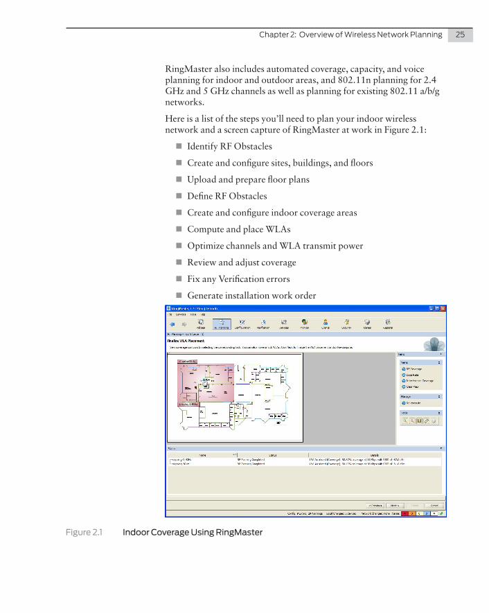
RingMaster also includes automated coverage, capacity, and voice planning for indoor and outdoor areas, and 802.11n planning for 2.4 GHz and 5 GHz channels as well as planning for existing 802.11 a/b/g networks.
Here is a list of the steps you’ll need to plan your indoor wireless network and a screen capture of RingMaster at work in Figure 2.1:
� Identify RF Obstacles
� Create and configure sites, buildings, and floors
� Upload and prepare floor plans
� Define RF Obstacles
� Create and configure indoor coverage areas
� Compute and place WLAs
� Optimize channels and WLA transmit power
� Review and adjust coverage
� Fix any Verification errors
� Generate installation work order
Figure 2.1 Indoor Coverage Using RingMaster

26 DayOne:DeployingaSecureWirelessLAN
And for comparison, here is a list of steps used for planning outdoor wireless networks and a screen capture of Ringmaster working in the wild:
� Create and configure outdoor areas
� Upload and scale a plan or image
� Place RF obstacles
� Create and configure outdoor coverage areas
� Compute and place WLAs
� Review and adjust coverage
� Optimize channels and WLA transmit power
Figure 2.2 Outdoor Coverage Planning Using RingMaster RF Tools
UsingThirdPartyPlanningTools
There are also third party software packages such as Ekahau that allow you to perform site surveys by walking through the desired location of the network and taking RF measurements.

Chapter2:OverviewofWirelessNetworkPlanning 27
Ekahau Site Survey (ESS) is a simple-to-use software tool for profes-sional Wi-Fi (WLAN) network planning, site surveys, and administra-tion. ESS gives you a ground-level view of coverage and performance, and it enables you to quickly and easily create, improve, and trouble-shoot Wi-Fi networks.
Ekahau Site Survey works over any 802.11 network, and is optimized for modern, centrally-managed 802.11n Wi-Fi networks. Plus Ekahau is a Juniper technology partner, so it works with Juniper’s WLAN product suite.
MORE? Check out Ekahau at http://www.ekahau.com/.
Old School Planning
If your site is simple, or if you decide that you don’t want to use automated network planning tools, you can always use a simple grid pattern to place your WLAs. Assuming that each access point can provide high data rate service up to 50 feet from a WLA, you can place the access points as shown in Figure 2.3.
30'
OFFICEOFFICEOFFICE OFFICE
OFFICE
OFFICE
OPEN OFFICE
TELE
COMPUTER
SHIPPINGOFFICEMEZZ
STG OFFICE
OFFICE OFFICE
BREAKROOM
ROOM
STORAGE
STORAGE
OFFICEOPEN
TRAINING
OFFICE
STG
OFF OFFICE
OPEN OFFICE
OFFICE OFFICE
ROOM
LOBBY
MEN
TRAININGOFFICE
WOMEN
OFFICE
OFFICE
OFFICEOFFICEOFFICE
ELECT.
OPEN OFFICE OPEN OFFICE
STG
EXITEMERGENCY
OFFICE
OFFICE
OPEN OFFICE
RESTREST RM. RM.
OFFICE
STORAGE
STG
W/MEZZ ABOVE
STORAGE
STGTELE
EXITEMERGENCY
OPENOFFICE
BREAK
OFFICE
OFFICE
DEMO
OPEN OFFICE
OFFICEOFFICEOFFICE
OFFICE
OPEN OFFICE
Figure 2.3 A Simple Grid Approach to Placing WLAs

28 DayOne:DeployingaSecureWirelessLAN
Or, you can estimate that one WLA supports 20-25 users and place the WLAs on the grid with additional WLAs in areas with more users.
With your plan in place, install the WLAs. Use the installation guide that comes with the products. Once installed, let’s get into your lab or server room and begin the deployment.
Chapter 3
The Components of a Wireless LAN
Distributed WLAs . . . . . . . . . . . . . . . . . . . . . . . . . . . . . . . . . . . . . . . . . . . . . . . . . . . 30
How Do WLAs Boot Up on the Network? . . . . . . . . . . . . . . . . . . . . . . . . . . . . . 30
A Word About Operational Images on WLAs . . . . . . . . . . . . . . . . . . . . . . . . . . 36
30 DayOne:DeployingaSecureWirelessLAN
WLAs contain radios that provide connections between your wired network and IEEE 802.11 clients. They connect to the wired network through a 10/100 Ethernet link and connect to wireless users through radio signals. This chapter reviews some of the decisions that you’ll have to make regarding the particulars of your site, and then we’ll start configuring.
Distributed WLAs
To be able to configure the WLA, you must choose how the WLA connects to the WLC. You can connect a WLA directly to the WLC, but that’s a topic for a different wireless book.
The WLA is not directly connected to the WLC, but is connected to a Layer 2 or Layer 3 switch between the WLA and WLC. Communica-tion occurs over any subnet on the network. You must also provide PoE on the connection to the WLA as well as DHCP services on the network. We’ll go over DHCP requirements and booting processes in the next section.
How Do WLAs Boot Up on the Network?
Now, if you've been astutely following along, you’re at the magical part of wireless networking where you ask the question: How does that WLA talk to the WLC if the WLA is wireless?
There are four methods for a distributed WLA to discover and estab-lish contact with a WLC on the wireless network, listed here in the order used on the network:
� DHCP Option 43
� DNS Lookup
� L2 Broadcast
� Static IP
Since WLAs use DHCP to get IP addresses, you should have DHCP services running on your network. You probably do, but check and make sure this option is available before you begin configuring the wireless network. DHCP must give the WLA the following informa-tion:
� IP Address
� Default Router Address
� Domain Name (Optional)
� DNS Server Address (Optional)

Chapter3:UsingtheQuickstartCommand 31
Spanning Tree Protocol (STP) and WLAs
A DAP is a leaf device and you do not need to have Spanning Tree Protocol (STP) enabled on a port directly connected to the WLA. In fact, if you do, you can prevent the WLA from booting properly.
If you must allow a WLA to boot over a link with STP enabled, take one of the following actions:
� Disable STP on the port of the other device.
� Enable port fast convergence on the port of the other device.
� If the other device is running Rapid Spanning Tree, or Multiple Spanning Tree, configure the port for edge port mode.
BootingWLAsUsingDHCPOption43
The Option 43 field in a DHCP Offer message provides a simple and effective way for WLAs to find WLCs across an intermediate Layer 3 network. It is very useful in geographically distributed networks or networks with a flat domain name space. You can use the DHCP option 43 field to provide a list of WLC IP addresses without configuring DNS servers.
Configure DHCP option 43 with a comma-separated list of WLC addresses or hostnames, in the following format:
ip: ip-addr1,ip-addr2,...
or:
host: hostname1,hostname2, ...
So in our example network, the list of IP addresses looks like this:
ip: 172.24.111.110, 172.24.111.112
You can’t use an IP address list and a host list at the same time. You have to use one or the other. Let’s examine a DAP using broadcast messages and DHCP Option 43 as illustrated here in Figure 3.1.
The chain of events in Figure 3.1 is:
1. DAP1 sends a DHCP Discover message from WLA port 1 (wired network port).
2. DHCP server receives the Discover message (through a relay agent) and replies with a DHCP Offer message containing the IP address for the WLA, the router IP address for the DAP1 IP subnet, the DNS server address, and the domain name. WLAN then sends a DHCP Request message to the server and receives an acknowledgment from the server.

32 DayOne:DeployingaSecureWirelessLAN
3. The WLA then configures itself with the information it receives from the DHCP server, and looks for an Option 43 list in the DHCP Offer message. If a list is available then the WLA sends a TAPA “Find WLC” message to each IP address or hostname in the list.
4. WLC1 and WLC3 have a high priority for the WLA and send replies immediately. (The WLCs are configured for high bias.)
5. The WLA contacts WLC1 and determines if it should use a locally stored operational image or download one from the WLC.
ºThe WLA becomes operational on the network and downloads the configuration file from the WLC.
DHCP Server
WLC1System IP 10.10.10.4Active WLAs = 49
DAP 1serial-id:032219999model:WLA532
DAP 1serial-id:032219999model:WLA532
1 3
4
5
2
EX Switch
LAN
Figure 3.1 WLA Booting Using DHCP Option 43

Chapter3:UsingtheQuickstartCommand 33
It’s worthwhile to take a minute and understand what the DNS server provides to the WLA, as you may not be familiar with the process as it applies to a WLA.
If the intermediate network between the distributed WLAs (DAPs) includes one or more IP routers, create a jnpr.mynetwork.com or wlc-switch.mynetwork.com entry on the DNS server. The entry needs to map one of these names to a WLC IP address. For redundancy, you can create more than one DNS entry and map each entry to a different WLC in the subnet.
The DNS entry allows the WLA to communicate with a WLC not on the WLA subnet. If the WLA can’t locate a WLC on the same subnet, it sends a DNS request to both JNPR and wlc-switch, and the DNS suffix for mynetwork.com is obtained through DHCP.
If you define only the JNPR DNS entry, the WLA contacts the WLC with an IP address returned for JNPR.
If you define only the wlc-switch DNS entry, the WLA contacts the WLC with the IP address for wlc-switch.
If both are defined, the WLA contacts the WLC with the IP address for JNPR and ignores the IP address for wlc-switch. In addition, if both are defined, and the WLA can’t contact the IP address for JNPR, the WLA doesn’t boot.
Rather straightforward, isn’t it? Let’s compare it to using DNS as illustrated in Figure 3.2 on the following page.
And the chain of events in Figure 3.2 is:
1. The WLA sends DHCP Discover message from port 1 on the WLA.
2. The DHCP server replies with a DHCP Offer message containing the IP address for the WLA, the default router IP address for the WLA IP subnet, the DNS server address, and the domain name. WLA then sends a DHCP Request message to the server and receives an acknowledgment from the server.
3. The WLA then sends a DNS request for JNPR.example.com and wlan-switch.example.com.
5. The DNS server sends the system IP address of the WLC mapped to JNPR.example.com or wlan-switch.example.com. In this example, the IP address is located on WLC1.
6. The WLA sends a unicast Find WLC message to WLC1.
7. The WLC sends its IP address in the WLC Reply message to the WLA.
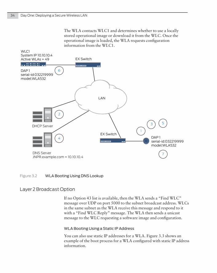
34 DayOne:DeployingaSecureWirelessLAN
The WLA contacts WLC1 and determines whether to use a locally stored operational image or download it from the WLC. Once the operational image is loaded, the WLA requests configuration information from the WLC1.
DHCP Server
WLC1System IP 10.10.10.4Active WLAs = 49
DAP 1serial-id:032219999model:WLA532
DAP 1serial-id:032219999model:WLA532
EX Switch
EX Switch
1
3
4
5
2
DNS ServerJNPR.example.com = 10.10.10.4
7
6
LAN
Figure 3.2 WLA Booting Using DNS Lookup
Layer2BroadcastOption
If no Option 43 list is available, then the WLA sends a “Find WLC” message over UDP on port 5000 to the subnet broadcast address. WLCs in the same subnet as the WLA receive this message and respond to it with a “Find WLC Reply” message. The WLA then sends a unicast message to the WLC requesting a software image and configuration.
WLA Booting Using a Static IP Address
You can also use static IP addresses for a WLA. Figure 3.3 shows an example of the boot process for a WLA configured with static IP address information.

Chapter3:UsingtheQuickstartCommand 35
WLC800RSystem FQDNmx800
Layer 2
DAP 1static IP 172.16.0.42
1
2
3
4
5
Figure 3.3 Static IP Address on a WLA
1. After the WLA is configured with the static IP address and controller IP address, the next time that the WLA boots on the network, the WLA sends an ARP request for the IP address to see if the IP address is available.
2. The WLA sends a Find WLC message to the WLC wlc8.
3. The WLC wlc8 responds to the Find WLC message.
4. The WLA sends a unicast message to WLC wlc8 and determines if the WLA should use a locally stored operational image or download it from the WLC.
5. Once the operational image is loaded, WLC wlc8 sends configuration information to the WLA.
36 DayOne:DeployingaSecureWirelessLAN
NOTE If the WLA does not receive a reply after 10 seconds, the WLA reboots and starts the boot process again. This applies to all four methods of booting a WLA on the network.
CountryofOperation
You must select the country code of the location at which you’re installing the WLA to meet regulations. Each country has different regulatory requirements and the country code determines the transmit power level (strength of transmitted signal) and channels. To stay on the right side of the law use the country code of the country in which you are physically installing the WLA.
A Word About Operational Images on WLAs
A WLA operational image is software that allows the WLA to function as a wireless access point on the network. As part of the WLA boot process, an operational image is loaded into the WLA RAM and activated. The WLA stores copies of the operational image locally in the internal flash memory. The WLA can either load the local image or download an operational image from a connected WLC.
After the WLA establishes a connection to the WLC, the WLA boot-loader determines if the WLC is configured to allow the WLA to load a local image. If the MSS version on the WLC is old, or the WLC has a different image than the WLA local image, the WLA downloads the operational image from the WLC.
The bootloader also compares the WLA local image version to the image version on the WLC. If the versions don’t match, then the image is downloaded from the WLC to the WLA.
After the operational image is downloaded from the WLC, the image is copied into the WLA flash memory. The WLA reboots, and copies the new version from the flash memory to the RAM. In addition, the WLA receives the configuration information from the WLC and becomes functional on the network as an active WLA.
So now that you know how software images are loaded onto a WLA from a WLC, let’s move on to configuring the wireless network.

Chapter 4
Using the Quickstart Command
Using the CLI on a WLC . . . . . . . . . . . . . . . . . . . . . . . . . . . . . . . . . . . . . . . . . . . . . . 38
Using the Serial Console Port on the WLC . . . . . . . . . . . . . . . . . . . . . . . . . . . . . 39
Configuring Wireless Access . . . . . . . . . . . . . . . . . . . . . . . . . . . . . . . . . . . . . . . . . 42
Adding WLAs to the Wireless Network . . . . . . . . . . . . . . . . . . . . . . . . . . . . . . . 47

38 DayOne:DeployingaSecureWirelessLAN
Using the Quickstart command is the easiest way of getting your WLC configured and adding WLAs. All you need to do is follow the steps and answer the questions about the parameters used on your wireless network. Brief explanations about each question are provided so you know the impact of your answer on the configuration.
However, using the complete Quickstart procedure configures some parameters by default, so in order to have more control over the configu-ration, let’s divide the configuration into two steps:
� Initial WLC configuration
� Wireless configuration
Using the CLI is not the only way to access a WLC to configure it.
� You can also access a Web-based interface called WebView which allows you to use a GUI to configure the WLC. WebView has limited functionality, so not all features are available to you, and you can explore the GUI on your time.
� You can configure a WLC if you have RingMaster software installed on your network. This method also allows you to config-ure a WLC using a GUI, and it has the full feature set of the CLI.
� Another technique for configuring WLCs is called auto provision-ing or drop ship configuration. You can preconfigure a WLC2 (not other WLC models) using RingMaster and send it to a remote site on the corporate network. Once you’ve entered the WLC2 IP address on the corporate DNS server and the WLC2 boots up in the remote location, the WLC uses DHCP to obtain an IP address to communicate with the RingMaster server.
MORE? You can find more information on configuring and deploying a WLC in the Wireless LAN Controllers Installation Guide at http://www.juniper.net/techpubs/en_US/release-independent/wireless/information-products/pathway-pages/wireless-lan/index.html.
Using the CLI on a WLC
It might be helpful to understand how the CLI functions on the WLC. It’s different enough from the Junos OS to briefly describe the commands used by MSS here.
Mobility System Software (MSS) supports a Juniper Networks Mobility System wireless LAN (WLAN) consisting of RingMaster software, WLC switches, and WLA access points. MSS has a command-line interface (CLI) on the WLC that you can use to configure and manage the WLC and the attached WLAs.

Chapter4:UsingtheQuickstartCommand 39
You configure the WLC and the WLA primarily with set, clear, and show commands:
� Use set commands to change parameters.
� Use clear commands to reset parameters to their defaults. In many cases, you can overwrite a parameter with another set command.
� Use show commands to display the current configuration and monitor the status of network operations.
You can only use set and clear commands when the CLI is in “enable” mode. Show commands can be used without accessing enable mode.
Text Entry Conventions and Allowed Characters
Unless otherwise indicated, the MSS CLI accepts standard ASCII alphanumeric characters, except for tabs and spaces. It is case-insensi-tive.
The CLI has specific notation requirements for MAC addresses, IP addresses, and masks, and allows you to group usernames, MAC addresses, virtual LAN (VLAN) names, and ports in a single com-mand. It is recommended that you do not use the same name with different capitalizations for VLANs or access control lists (ACLs). For example, do not configure two separate VLANs with the names red and RED. Okay, let’s start using the CLI.
Using the Serial Console Port on the WLC
You should now be familiar with the discovery process for the WLAs on the network, so let’s connect to the WLC using a serial console port, and access the CLI for MSS using a standard RS-232 serial connection and cable.
To Connect a Computer to the Serial Console Port:
1. Connect the serial cable to the port on the computer.
2. Connect the other end of the cable to the serial console port on the WLC.
3. Start a standard VT100 terminal emulation application, such as TeraTerm Pro, on the computer.
4. Configure the following modem settings:
� 9600 bps
� 8 bits

40 DayOne:DeployingaSecureWirelessLAN
� 1 stop
� No parity
� Hardware flow control off or disabled
5. Open a connection on a serial port.
6. Be sure that the WLC is powered on, and then press Enter on your keyboard three times to display the command prompt:
WLC>
7. If a command prompt does not appear:
� Verify that the WLC is powered on by checking that the Power LED is green.
� Verify that the serial cable is fully connected to the computer and the WLC.
� Verify that the correct modem settings are configured in the terminal emulation application.
8. Verify that you opened the correct serial port on the computer port connected to the WLC. For instance, if you inserted the cable on the computer port COM1, make sure you open the same port using the terminal emulation application.
9. If none of the previous steps correct the problem, try another serial cable.
AccessingtheMSSCLI
Now that you’ve successfully connected to your WLC using the serial console port, it’s time to get into the CLI and begin your configuration process.
How to Configure the WLC1 With the IP Address 172 .24 .111 .110
1. With your terminal emulation window open, press Enter on your keyboard three times to display the CLI:
WLC880-aabbcc>
(Each WLC has a unique system name that contains the model number and the last half of the WLC MAC address.)
2. Access the enabled level of the CLI by typing enable at the com-mand prompt:
WLC880-aabbcc>enable

Chapter4:UsingtheQuickstartCommand 41
The command prompt changes from a > to a # indicating that you can now configure the WLC:
WLC880-aabbcc#
3. At the Enter password prompt, press Enter on your keyboard. You’ll configure a password during the initial configuration.
4. At the command prompt, type quickstart.
Now let’s begin configuring the WLC and the corresponding WLAs. What is keyed into the CLI will appear in boldface.
Configuring System Information
WLC880-aabbcc# quickstartThis will erase any existing config. Continue? [n]: y
Type y and press Enter to respond “yes”.
You’ll see the following information about the Quickstart command:
Answer the following questions. Enter ? for help. ̂ C to break out.
NOTE Default values are indicated by [ ] following the question. You can press Enter to continue accepting default values.
System Name [WLC880]: WLC1Country Code [US]: USSystem IP address: 172.24.111.110System IP address netmask []: 255.255.255.0Default route []: 172.24.111.1
AddingTaggedVLANPorts
In some cases, when VLANs are applied across multiple WLCs, you may want to use VLAN tagging on your network.
If you’re familiar with VLAN tagging and it’s required for your network topology, then use VLAN tagging on the WLC.
Do you need to use 802.1Q tagged ports on the default VLAN? [n]: n
Enabling WebView
WebView is the GUI that you can use to configure the WLC instead of using the CLI. WebView is accessible using a network cable, a com-puter, and a WLC. See the MSS Configuration Guide for more infor-mation on this feature.
Enable WebView [y]: y

42 DayOne:DeployingaSecureWirelessLAN
Configuring Admin Access
In these steps, you add an admin name, a password, and configure the enable password that allows you to put the CLI in configuration mode.
Admin username [admin]: wlcadminAdmin password [mandatory]: letmeinEnable password [optional]: wlcconfig
Setting the Date and Time
In these steps, you configure the date, time, and time zone for the WLC.
Did you wish to set the time? [y] yEnter the date (dd/mm/yy) []: 01/01/12Enter the time (hh:mm:ss) []: 02:30:30Enter the timezone []: PSTEnter the offset (without DST) from GMT for ‘PST’ in hh:mm [00:00]: -8:0
The next question is about configuring wireless, so we’ll answer no and save the configuration.
Do you wish to configure wireless? [y]: nsuccess: created keypair for sshsuccess: Type ‘save config’ to save the configuration.
Save the configuration.
WLC1# save configsuccess: configuration saved.
Configuring Wireless Access
If you remember, ACME Roundtuit wanted two groups of users with access to the wireless network: employees and guests. You’ll need two VLANs, one for each group, and two different service profiles. Your employees will access the wireless network on one SSID and authenti-cate using your RADIUS server. Your guests will access the wireless network on another SSID and authenticate using the captive Web portal method.
Let’s configure the VLANs first.
Creating the VLANs
You need the following VLANs on the wireless network:
� Corporate VLAN (acme-corp)
� Guest VLAN (acme-guest)

Chapter4:UsingtheQuickstartCommand 43
Let’s create both VLANs:
WLC1# set vlan 2 name acme-corpsuccess: change accepted.
WLC1# set vlan 3 name acme-guestsuccess: change accepted.
Save the configuration.
WLC1# save configsuccess: configuration saved.
Now assign the VLANS to ports on the WLC.
WLC1# set vlan acme-corp port 3success:change accepted.
WLC1# set vlan acme-guest port 5success:change accepted.
Assigning the VLANs to IP Interfaces
By default, the Quickstart command uses the WLC IP address for the default VLAN. For our use case, you’ll need to remove the IP address from the default VLAN first and then map it to the VLANs you just created.
WLC1# clear interface 1 ipsuccess: change accepted.
WLC1# set interface acme-corp ip 172.24.111.110/24success: change accepted.
WLC1# set interface acme-guest ip 172.24.112.111/24success: change accepted.
Save the configuration.
WLC1# save configsuccess: configuration saved.
Now you can add a guest SSID for guest access to the wireless network. You can do this as part of adding a service profile that provides captive Web portal authentication.
WLC1# set service-profile acme-guest ssid-name acme-guestsuccess: change accepted.
WLC1# set service-profile acme-guest ssid-type clearsuccess: change accepted.
WLC1# set service-profile acme-guest auth-fallthru web-portalsuccess: change accepted.
44 DayOne:DeployingaSecureWirelessLAN
WLC1# set service-profile acme-guest attr vlan-name acme-guestsuccess: change accepted.
WLC1# set authentication web ssid acme-guest ** localsuccess: change accepted.
Save the configuration.
WLC1# save config
You can use the command show service-profile acme-guest to verify the changes.
The configuration above allows UDP traffic from users to port 68 and 67 only, which is used for DHCP. The authentication rule creates a capture for all traffic matching this rule and forces it to the Web portal for authentication.
By default, when you set the fallthru authentication type on a service profile to Web portal, MSS creates an ACL called portalacl. MSS uses the portalacl ACL to filter Web-Portal user traffic while users are authenticating on the network.
Adding a Guest User to the Local Database
To allow users guest access on the network, you can configure a username and password in the local database, so let’s do that now. You can configure a single username and password for anyone requesting guest access to the wireless network. If you anticipate that you’ll have a lot of guest users, you should look at SmartPass software as a solution for your network.
Since it’s a little obvious to use acme-guest as the user and password, we’ll use roundtuit-guest as the username and needroundtuits for the password.
WLC1# set user roundtuit-guest passwordEnter the new password: needroundtuitsRetype new password: needroundtuitssuccess: change accepted.
The CLI doesn’t display the password as you type it. It’s a security thing – no one can look over your shoulder and see what you’re typing as the password.
Now you can map the user to the acme-guest SSID, which only allows this user account to be used on the guest network.
WLC1# set user roundtuit-guest attr ssid acme-guestsuccess: change accepted.
Chapter4:UsingtheQuickstartCommand 45
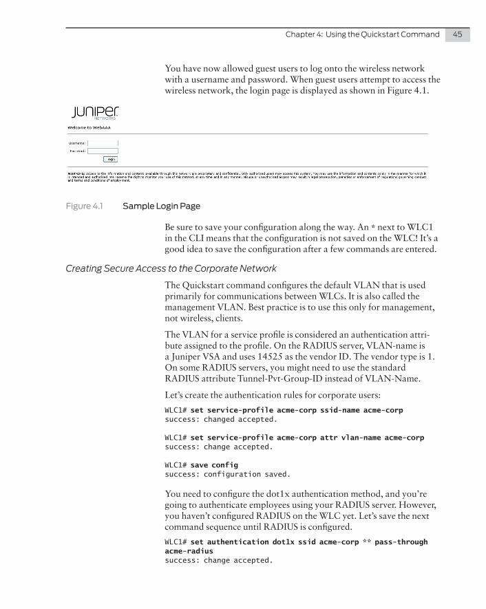
You have now allowed guest users to log onto the wireless network with a username and password. When guest users attempt to access the wireless network, the login page is displayed as shown in Figure 4.1.
Figure 4.1 Sample Login Page
Be sure to save your configuration along the way. An * next to WLC1 in the CLI means that the configuration is not saved on the WLC! It’s a good idea to save the configuration after a few commands are entered.
Creating Secure Access to the Corporate Network
The Quickstart command configures the default VLAN that is used primarily for communications between WLCs. It is also called the management VLAN. Best practice is to use this only for management, not wireless, clients.
The VLAN for a service profile is considered an authentication attri-bute assigned to the profile. On the RADIUS server, VLAN-name is a Juniper VSA and uses 14525 as the vendor ID. The vendor type is 1. On some RADIUS servers, you might need to use the standard RADIUS attribute Tunnel-Pvt-Group-ID instead of VLAN-Name.
Let’s create the authentication rules for corporate users:
WLC1# set service-profile acme-corp ssid-name acme-corpsuccess: changed accepted.
WLC1# set service-profile acme-corp attr vlan-name acme-corpsuccess: change accepted.
WLC1# save configsuccess: configuration saved.
You need to configure the dot1x authentication method, and you’re going to authenticate employees using your RADIUS server. However, you haven’t configured RADIUS on the WLC yet. Let’s save the next command sequence until RADIUS is configured.
WLC1# set authentication dot1x ssid acme-corp ** pass-through acme-radiussuccess: change accepted.

46 DayOne:DeployingaSecureWirelessLAN
This command uses the 802.1X passthrough method to send EAP authentication requests to the acme-radius server group.
Mapping Service Profiles to the Radio Profiles
Now that your service profiles are configured, you need to map them to the default radio profiles so that the new SSIDs are advertised on the network.
WLC1# set radio-profile default service-profile acme-guestsuccess: change accepted.
WLC1# set radio-profile default service-profile acme-corpsuccess: change accepted.
Save the configuration.
WLC1# save configsuccess: change accepted.
Additional Access Commands
To enable Telnet access to the WLC, use the following command:
WLC1# set ip telnet server enablesuccess: change accepted.
To enable SSH access to the WLC, use the following command:
WLC1# set ip ssh server enablesuccess: change accepted.
DisplayingtheConfiguration
WLC1# show config# Configuration nvgen’d at 2012-2-23 10:03:16# Image 7.7.2.3# Model WLC880# Last change occurred at 2012-2-23 08:20:44set ip route default 172.24.111.1set system name WLC1set system ip-address 172.24.111.110set system countrycode USset timezone pst -8 0set service-profile acme-corp ssid-name acme-corpset service-profile acme-corp attr vlan-name acme-corpset service-profile acme-guest ssid-name acme-guestset service-profile acme-guest ssid-type clearset service-profile acme-guest auth-fallthru web-portalset service-profile acme-guest web-portal-acl portalaclset service-profile acme-guest wpa-ie auth-dot1x disableset service-profile acme-guest rsn-ie auth-dot1x disableset service-profile acme-guest attr vlan-name acme-guest

Chapter4:UsingtheQuickstartCommand 47
set enable password e767a83ddcbd1c28e7af252lace0fc32c91set authentication dot1x ssid acme-guest ** localset user admin password encrypted 051b161fset user roundtuit-guest password encrypted 151e0e09003842431263721371a1305set user roundtuit-guest attr ssid acme-guestset radio-profile default service-profile acme-guest-svprofset radio-profile default service-profile acme-corp-svprofset vlan 1 port 1set vlan 1 port 2set vlan 2 name acme-corp port 3set vlan 3 name acme-guest port 5set interface 2 ip 172.24.111.110 255.255.255.0set interface 3 ip 172.24.112.111 255.255.255.0set radio-profile default service-profile clear-acme-guestset radio-profile default service-profile crypto-acme-corpset security acl name portalacl permit udp 0.0.0.0 255.255.255.0 eq 68 0.0.0.0 255.255.255.0 eq 67commit security acl portalacl
Test your connectivity to the default route by pinging 172.24.111.1:
WLC1# ping 172.24.111.1PING 172.24.111.1 (172.24.111.1) from 172.24.111.110 : 56(84) bytes of data.Reply from 172.24.111.1: bytes=56 time<1ms TTL=64Reply from 172.24.111.1: bytes=56 time<1ms TTL=64Reply from 172.24.111.1: bytes=56 time<1ms TTL=64Reply from 172.24.111.1: bytes=56 time<1ms TTL=64Ping statistics for 1723.24.111.1: Packets: Sent = 4, Received = 4, Lost = 0 <0% loss>,Approximate round trip times in milli-seconds: Minimum = 0ms, Maximum = 0ms, Average = 0ms
Adding WLAs to the Wireless Network
Since we have ten WLAs installed in the right locations, let’s get them booted up and running on the network. You can use the auto ap command to easily add the WLAs:
WLC1# set ap auto mode enablesuccess: change accepted.
Save the configuration.
WLC1# save configsuccess: configuration saved.
After the WLAs have booted up on the network, you can see the status using the show ap status command.
NOTE Since you used ap auto mode, WLAs are assigned AP numbers auto-matically starting with 9999.

48 DayOne:DeployingaSecureWirelessLAN
WLC1# show ap statusFlags: o = operational[8], c = configure[0], d = download[0], b = boot[0] a = auto AP, m = mesh AP, p/P = mesh portal (ena/actv), r =redundant[0] z = remote AP in outage, i/I = insecure (control/control+data) u = unencrypted, e/E = encrypted (control/control+data)Radio: E = enabled - 20MHz channel, S = sentry, s = spectral-data W/w = enabled - 40MHz wide channel (HTplus/HTminus) D = admin disabled, U = mesh uplinkIP Address: * = AP behind NATAP Flag IP Address Model MAC Address Radio 1 Radio 2 Uptime---- ---- --------------- ------------ ----------------- ------- ------- ------9990 oa-i 117.24.111.25 MP-532 78:19:f7:7c:12:40 E 44/11 W 44/10 01m09s9991 oa-i 117.24.111.24 MP-532 78:19:f7:7c:12:21 E 11/12 W 36/10 01m10s9992 oa-i 117.24.111.22 MP-532 78:19:f7:7c:12:63 E 6/18 W 36/10 01m05s9993 oa-i 117.24.111.26 MP-532 78:19:f7:7c:12:27 E 6/12 W 44/10 01m06s9994 oa-i 117.24.111.27 MP-532 78:19:f7:7c:12:18 E 11/12 W 44/10 01m06s9995 oa-i 117.24.111.23 MP-532 78:19:f7:7c:12:54 E 11/12 W 36/10 01m06s9996 oa-i 117.24.111.21 MP-532 78:19:f7:7c:12:45 E 11/12 W 44/10 01m07s9997 oa-i 117.24.111.29 MP-532 78:19:f7:7c:12:33 E 1/14 W 36/10 01m08s9998 oa-i 117.24.111.28 MP-532 78:19:f7:7c:12:41 E 11/12 W 44/10 01m09s9999 oa-i 117.24.111.31 MP-532 78:19:f7:7c:12:44 E 11/12 W 36/10 01m10s
Wow, that was easy! All ten WLAs booted up on the network and located the WLC with the configuration that they needed, using a single command. Pat yourself on the back – great job!
There’s a little more to do to get your wireless network operational but you’ve completed the core configuration.

Chapter 5
Additional Configurations for the Wireless LAN
Configuring More Admin Users . . . . . . . . . . . . . . . . . . . . . . . . . . . . . . . . . . . . . . . 50
Adding an NTP Server . . . . . . . . . . . . . . . . . . . . . . . . . . . . . . . . . . . . . . . . . . . . . . . 50
Adding a RADIUS Server for Authentication . . . . . . . . . . . . . . . . . . . . . . . . . . . .51

50 DayOne:DeployingaSecureWirelessLAN
There are additional steps that are an extension of the Quickstart configuration that allow you to configure additional admin users, set up a NTP server, and add a RADIUS server.
Follow along with your test bed or lab.
Configuring More Admin Users
You can add additional administrators to authenticate against the local database. That way, when you go on vacation (or do you?) someone on your team can access the WLCs. So let’s add your teammate, Peter Jones, to the local database:
WLC# set user pjones password s1llyputtysuccess: change accepted.
You should also add yourself to the local user database before you go any further.
WLC# set user yourself password gl0ww0rmsuccess:change accepted.
Okay, you should feel a little better now. Let’s save it.
WLC# save configsuccess: configuration saved.
If you want to add more users, you can add up to 100 on the local database, just use the set user command.
MORE? For more information about additional admin users, see the MSS Configuration Guide at http://www.juniper.net/techpubs/en_US/release-independent/wireless/information-products/pathway-pages/wireless-lan/software-77.html.
Adding an NTP Server
Even though you configured the time on the WLC using the Quickstart command, you can configure the WLC to use your NTP server for time configuration:
WLC# set ntp server 172.24.111.10success: change accepted.
The update interval is 64 seconds, but it is recommended to set the time on the WLC to the time on the NTP server to avoid significant delays in convergence time on the WLC. Let’s check to see if the NTP server is updating properly. From the WLC1 CLI:

Chapter5:AdditionalConfigurationsfortheWirelessNetwork 51
WLC1# show ntp NTP client: enabledCurrent update-interval: 64(seconds)Current time: Tue May 15, 2012 02:56:03Timezone is set to ‘PDT’, offset from UTC is -8:00 hours.NTP Server Peer state Local State--------------------------------------------172.24.111.10 SYSPEER SYNCED
Adding a RADIUS Server for Authentication
RADIUS is an identity server system and provides a repository for all usernames and passwords. But you knew that already! In our case, RADIUS servers store user profiles that include usernames, passwords, and other AAA attributes. Authorization attributes are used to authorize users for a type of service, appropriate servers and network segments, through VLAN assignments, for packet filtering by ACLs (firewall filters is the JUNOS term), and for other services during a session. Let’s take a look at the interaction between wireless clients, WLAs, a WLC, and RADIUS servers in Figure 5.1.
Client with Wireless Laptop
RADIUS Server 1
RADIUS Server 2
Client with Smart Phone
Client with TabletWLA1 WLA2
WLC880
Wired Connection
Wireless Connection
4
1
2
3
Figure 5.1 Interaction Between WLAs, a WLC, and RADIUS Servers

52 DayOne:DeployingaSecureWirelessLAN
The following events occur on the network shown in Figure 5.1:
1. The wireless user (client) requests an IEEE 802.11 association from the WLA.
2. After the WLA creates the association, the WLC sends an Extensible Authentication Protocol (EAP) identity request to the client.
3. The client sends an EAP identity response.
4. From the EAP response, the WLC receives the client username. The WLC then sends the information to the RADIUS server and the RADIUS server searches the AAA configuration, and attempts to match the client username with the users in the AAA configuration.
When a match is found, the methods specified by the matching AAA command determine client authentication, either locally on the WLC, or on a RADIUS server group. In this case, the client authentication information is located on a RADIUS server.
BeforeYouBegin
Make sure you can contact the RADIUS server on your network by using the ping command from the CLI. In this example, our RADIUS server has an IP address of 172.24.111.15. From the WLC1 CLI:
WLC1# ping 172.24.111.15Pinging 172.24.111.15 with 32 bytes of data:Reply from 172.24.111.15: bytes=32 time<1md TTL=64Reply from 172.24.111.15: bytes=32 time<1md TTL=64Reply from 172.24.111.15: bytes=32 time<1md TTL=64Reply from 172.24.111.15: bytes=32 time<1md TTL=64Ping statistics for 172.24.111.15: Packets: Sent 4, Received 4, Lost = 0(0% loss),Approximate round trip times in milli-seconds: Minimum = 0ms, Maximum = 0ms. Average = 0ms
If the ping is successful, then you can continue with your RADIUS set up between the WLC and the RADIUS server. If it’s not successful, then you’ll have to troubleshoot the connection before moving ahead with the RADIUS configuration.
ConfiguringRADIUSServers
When a RADIUS server is used for authentication, you must configure the RADIUS server parameters as follows:
� Server Name
Chapter5:AdditionalConfigurationsfortheWirelessNetwork 53
� Password (Key) or Shared Secret
� IP Address
If the RADIUS server does not have explicit values for dead times, timeout timers, and transmission attempts, MSS sets the following values by default:
� Dead time – 5 minutes
� Transmission Attempts – 3
� Timeout (server response time) – 5 seconds
When MSS sends an authentication or authorization request to a RADIUS server, MSS waits the length of the configured timeout for the server to respond (5 seconds by default). If the server does not respond, MSS retransmits the request. The request is resent depending on the configured number of transmission attempts.
Deadtime is generally used so that the WLCs can determine if a RADIUS server is unreachable or if the corresponding RADIUS server is down for the configured number of minutes.
You’ll also want to set the source address for the packets to the IP address of the WLC. The WLC IP address is used by default, but if routing conditions change, then the source IP address changes. If you set the system IP address as the source IP address, then it becomes the permanent source address for RADIUS packets sent by the WLC.
WLC1# set radius client system-ipsuccess:change accepted.
Now let’s add the RADIUS server information to the WLC, by adding the IP address and creating a name for the server. Let’s call the server radius1:
WLC1# set radius server radius1 address 172.24.111.115 key p0p0ver$Success:change accepted.
You can configure multiple RADIUS servers on the WLC, but before you do, you have to add it to a RADIUS server group. So let’s create the RADIUS server group, acme-radius and add the current RADIUS server to it. Then you’re good to go to add more servers whenever the demand requires it.
WLC1# set server group acme-radius member radius1Success: change accepted.

54 DayOne:DeployingaSecureWirelessLAN
Let’s test the RADIUS server by using the radping command:
WLC1# radping group acme-radius request authentication user pjones password bongos auth-type mschapv2
This command sends an authentication request with the specified username and password to the RADIUS server or RADIUS server group.
WCL1# radping group acme-radius member radius1 request authentication user jcash password bongos mschapv2Sending authentication request to group acme-radius (172.24.111.115)Received Access-Accept from the group in 17 ms Attributes: Ms-mppe-send-key = 0x88079324507a7795efc0fb3909c2bc4b Ms-mppe-recv-key = 0xb2a0195a0a190c0071c8b44bc517ed19 Encryption-type = 32 Service-type = 2 Ssid = acme-corp Termination-action = 0 Vlan-name = acme-corp Acct-interim-interval = 1000
MORE? For more information on setting up your wireless network for RADIUS access, see the MSS Configuration Guide http://www.juniper.net/techpubs/en_US/release-independent/wireless/information-products/pathway-pages/wireless-lan/ software-77.html.
MORE? Configuring the RADIUS server is outside the scope of this Day One book, but Juniper does have products available to provide RADIUS authentication on your network. See http://www.juniper.net/us/en/products-services/security/uac/#features-benefits.
Adding RADIUS Authentication to acme-corp
Remember that step while you were creating the acme-corp service profile where you were supposed to add RADIUS authentication? Let’s do that now:
WLC1# set authentication dot1x ssid acme-corp ** pass-throughsuccess: change accepted.
Employees on the SSID, acme-corp, are now authenticated on the RADIUS server.
Chapter 6
Testing Connectivity on the Wireless LAN
Preparing Clients for Wireless Connectivity . . . . . . . . . . . . . . . . . . . . . . . . . . . 56

56 DayOne:DeployingaSecureWirelessLAN
Now that the wireless network is configured, you should be ready to let users access the network. Let’s figure out how to configure a wireless client on a Windows XP laptop.
Preparing Clients for Wireless Connectivity
MSS uses 802.1X for access to secure (encrypted) SSIDs, like acme-corporate, using dynamic keys. To allow a wireless client access on an encrypted SSD with dynamic keys, 802.1X must be configured on the client.
Time to set up that laptop!
ConfiguringaClientforGuestAccess
Let’s configure a Windows laptop for guest access to the public net-work and see if things are working from this perspective. The exact procedure, of course, depends on your operating system and hardware:
1) On your Windows 7 PC, right-click the Wireless icon on the toolbar at the bottom right of the screen.
2) Select acme-guest from the list of available wireless networks.
3) Double-click and wait for a successful connection.
4) Once you're connected, the Web Portal page is displayed.
5) Log in using the configured username of roundtuit-guest and the password needroundtuits.
ConfiguringaClientforCorporateAccess
Now let’s configure a Windows 7 client for access to an encrypted SSID. The exact procedure, of course, depends on your operating system and hardware:
1. In Windows 7, go to Control Panel > Network and Internet > Network and Sharing Center.
2. Under Change Your Network Settings, click Manually connect to a wireless network.
3. Enter acme-corp as the Network name.
4. From the Security type list, select WPA2-Enterprise.
5. Leave the Encryption type as AES.
6. The default authentication method is Microsoft:Protected EAP (PEAP).
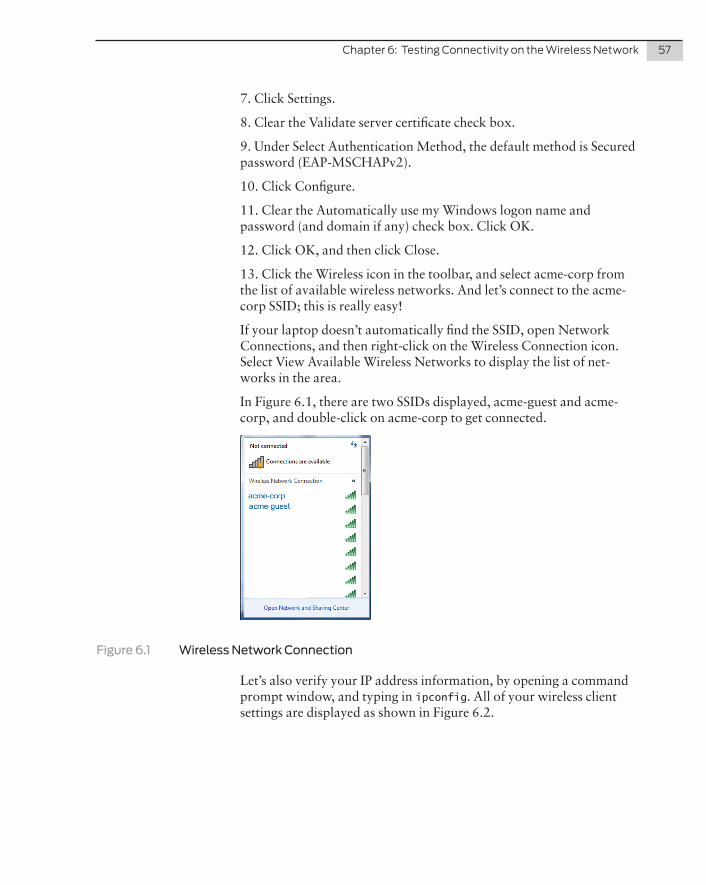
Chapter6:TestingConnectivityontheWirelessNetwork 57
7. Click Settings.
8. Clear the Validate server certificate check box.
9. Under Select Authentication Method, the default method is Secured password (EAP-MSCHAPv2).
10. Click Configure.
11. Clear the Automatically use my Windows logon name and password (and domain if any) check box. Click OK.
12. Click OK, and then click Close.
13. Click the Wireless icon in the toolbar, and select acme-corp from the list of available wireless networks. And let’s connect to the acme-corp SSID; this is really easy!
If your laptop doesn’t automatically find the SSID, open Network Connections, and then right-click on the Wireless Connection icon. Select View Available Wireless Networks to display the list of net-works in the area.
In Figure 6.1, there are two SSIDs displayed, acme-guest and acme-corp, and double-click on acme-corp to get connected.
Figure 6.1 Wireless Network Connection
Let’s also verify your IP address information, by opening a command prompt window, and typing in ipconfig. All of your wireless client settings are displayed as shown in Figure 6.2.

58 DayOne:DeployingaSecureWirelessLAN
Figure 6.2 Verifying IP Addresses
Let’s also verify an outside IP address to confirm access to the Internet with a ping to a known entity as shown in Figure 6.3.
Figure 6.3 Verifying Access to the Internet
AddingMoreClientstotheWLAN
Okay, now it’s time to grab your colleagues and walk them through the steps of configuring the wireless client on various mobile devices. If you’ve followed the configuration correctly, wireless clients should have no problem finding and connecting to your wireless network. Bring in all your mobile devices, and laptops, to document and test their connectivity. Update the drivers on laptops or tablets to be sure that you have the latest versions.
It’s not a perfect world, so the next chapter has useful information on troubleshooting wireless clients, connectivity, and WLC parameters.

Chapter 7
Troubleshooting Wireless Connectivity
FAQs on Wireless Client Connectivity . . . . . . . . . . . . . . . . . . . . . . . . . . . . . . . . . 61
Configuring and Managing the System Log . . . . . . . . . . . . . . . . . . . . . . . . . . . 66
About Logging Destinations . . . . . . . . . . . . . . . . . . . . . . . . . . . . . . . . . . . . . . . . . . 67
Upgrading MSS Software . . . . . . . . . . . . . . . . . . . . . . . . . . . . . . . . . . . . . . . . . . . .68
What to Do Next & Where to Go … . . . . . . . . . . . . . . . . . . . . . . . . . . . . . . . . . . . 70

60 DayOne:DeployingaSecureWirelessLAN
Your wireless network is up and running and clients are connecting – what could possibly go wrong? This chapter lists just a few consider-ations and issues that you might initially run into, as well as common connectivity problems.
Don’t be afraid to get your hands dirty as you dig into more specific knowledge about your wireless network and use the helpful show commands to analyze what’s happening.
Table 7.1 Fixing Common WLC Setup Problems
Symptom Diagnosis Remedy
WLC does not accept configuration information for a WLA or a radio.
The country code may not be set or might be set for another country.
Type show system to display the country code configured on the WLC. If it is not the country where the WLC is physically located, use the set system country code command to set the correct country code.
Client cannot access the network.
This symptom has more than one possible cause:
The client is failing authentication or isn’t authorized for a VLAN.
If the client and WLC configurations are correct, a VLAN might be disconnected. You cannot connect to the network over a disconnected VLAN.
Type one of the following commands:
show radius
show user
show mac-user
to ensure that the authentication rules on the WLC allow the client to authenticate.
Check the authorization rules for the local database or on the RADIUS servers to be sure that the client is authorized to join a VLAN configured on at least one of the WLCs in the MoDo.
Type the show vlan config command to check the status of each VLAN.
If a VLAN is disconnected, check one of the network cables for the VLAN port. At least one of the ports in a VLAN must have a physical link to the network for the VLAN to be connected.

Chapter7:TroubleshootingWirelessConnectivity 61
Configuration information disappears after a software reload.
The configuration changes were not saved.
Retype the commands for the missing configuration information.
Type the save config command to save the changes.
Mgmt LED is rapidly blinking amber.
CLI stops at the boot prompt (boot>)
The WLC was unable to load the system image file.
Type the boot command at the boot prompt to reload the image.
FAQs on Wireless Client Connectivity
I have a laptop that cannot connect to the network . What could be some possible reasons?
Be sure the wireless radio is turned on. Duh, but it might be turned off accidentally.
Check the closest AP to see if the LEDs are lit and green. Flashing amber LEDs indicate a problem on the AP. Go to http://www.juniper.net/techpubs and look for documentation on the WLA series. Check your network card configuration to be sure it is configured correctly.
Download the latest drivers for your network card. Old drivers are commonly an issue for a wireless card.
Open a command prompt and type ipconfig – you should be able to see if the wireless connection is getting an IP address.
Be sure that you’re not in a “dead zone” like a stairwell or reinforced concrete room.
My wireless connection is really slow – what could be the reason?
Too many wireless clients per radio – try load balancing clients across VLANs.
802.11b and 802.11g are slower than 802.11n – be sure the radio profiles are configured correctly to support 802.11n.
I want my corporate visitors to access the wireless network but I don’t want them in my private files . How do I configure this option?
Configure a clear SSID for public access.
Add a VLAN specifically for public clients.
Provision the rest of your network in other VLANs.
Install SmartPass to support guest services. Check with your Juniper reseller or partner for more information.

62 DayOne:DeployingaSecureWirelessLAN
The connection to the wireless network gets interrupted intermittently, what could cause that?
Look for possible sources of RF interference such as a microwave, cordless phone, or a Bluetooth device. Are you sitting in or near the break room at lunchtime? Is your colleague microwaving his lunch?
Check for interference using a WLA532 or WLA522 and the Spectrum Analysis feature.
What data should be gathered to troubleshoot a client connection issue?
Be sure to log the CLI session - the terminal program you are using to access the CLI should have a setting that allows you to capture text or log to file. Do not rely upon your cut-and-paste buffer to capture this information. To start troubleshooting:
1. Configure the WLC to set traces:
set trace dot1x level 10 set trace sm level 10
2. If you are having trouble authenticating against an external Radius server, also set trace:
set trace radius level 10
3. If you are having trouble authenticating with Web Portal, add the Web Portal to the traces:
set trace web level 10 mac
4. Test connectivity with the test client.
Begin Logging in the CLI Session
1. Issue the command set len 0. Use the number zero, not the letter O. This allows all the information to scroll through the screen.
2. Obtain the show tech output.
3. Obtain show roaming vlan and show mobility-domain at the time of failure.
4. Obtain show session output.
5. Obtain show log buffer.
6. Retrieve the traces by one of three methods:
� Save the trace file and then TFTP it from the MX.
Chapter7:TroubleshootingWirelessConnectivity 63
� Save trace <name>.txt save trace tftp://<ipa of tftp server>/trace.txt (saves trace in memory then immediately copies to a TFTP server)
� Log the CLI session to a file and issue the commands set len 0 and then show log trace (this could take some time)
7. Turn off all traces by issuing the clear trace all command.
NOTE To copy a file from the MX to a tftp server use the copy <file name on MX> tftp://<ip-tftpserver>/<filename> command.
LoggingtotheTraceBuffer
Trace logging is enabled by default and stores debug-level output in the WLC trace buffer. To set the severity higher than debug, use the following command:
WLC# set log trace severity severity-level
To save trace data to a file on the WLC, use this command:
WLC# save trace traces/trace1.txt
RunningTraces
Running trace commands enables you to perform diagnostic routines. You can set a trace command with a keyword such as authentication or sm, to trace activity for a particular feature, such as authentication or the session manager. Four areas that you might find useful are authentication, authorization, session manager, and 802.1X users (dot1x).
To run a trace, use the following command:
WLC# set trace area level level
MORE? To find out more about running traces, refer to the SS Configuration Guide at http://www.juniper.net/techpubs/en_US/release-independent/wireless/information-products/pathway-pages/wireless-lan/index.html.
64 DayOne:DeployingaSecureWirelessLAN
UsingShowCommands
To troubleshoot the WLC, you can use show commands to display information about different areas of MSS. The following commands are helpful if you have performance issues on the network.
Viewing VLAN Interfaces
To view interface information for VLANs, use the following command:
WLC# show interface* from DCHP
VLAN Name Address Mask Enabled State RIB--------------------------------------------------------------------------1 default 0.0.0.0 0.0.0.0 NO Down ipv4130 vlan-eng 192.168.12.7 255.255.255.0 YES Up ipv4190 vlan-wep 192.168.19.7 255.255.255.0 YES Up ipv4
Viewing User Sessions
You can display session information about users with admin access through SSH, Telnet, or console (admin), users with admin access through a console connection (console), users with admin access through a Telnet connection (telnet), or Telnet sessions from the CLI to remote devices. Most importantly, you can see wireless users on the network. To display information about all sessions:
WLC1# show sessionsUser Sess Type IP or MAC VLAN WLA/RadioName ID Address ----------------------------------------------------------------Eng-05:0c:78 28* dot1x 10.7.255.2 yellow 5/1Eng-79:86:73 29* dot1x 10.7.254.3 red 2/1Eng-1a:68:78 30* dot1x 10.7.254.8 red 7/1
To show specific users, add the admin, console, telnet, or telnet client options.
To view information about network sessions, type:
WLC1# show sessions networkUser Name SessID Type Address VLAN WLA/RadioACME\jjonesg 20* dot1x 172.24.111.151 default 20/2ACME\pstork 75* dit1x 172.24.111.157 default 2/2ACME\djones 75* dit1x 172.24.111.159 default 2/2ACME\mdoe 75* dit1x 172.24.111.161 default 2/2
To see all of the information about users on your network, use the show sessions verbose command.

Chapter7:TroubleshootingWirelessConnectivity 65
MORE? For more information on show sessions commands and the output, see the Juniper Networks MSS Command Reference at http://www.juniper.net/techpubs/en_US/release-independent/wireless/information-prod-ucts/pathway-pages/wireless-lan/index.html.
There are additional show commands that might also be helpful to you. You can display the forwarding database on the WLC:
WLC1# show fdb* = Static Entry. + = Permanent Entry. # = System EntryVLAN Tag Dest MAC/Route Des [Cos] Destination Ports Protocol Type--------------------------------------------------------------------------1 00:01:97:13:0b:1f 1 [ALL]1 aa:bb:cc:dd:ee:ff * 3 [ALL]1 00:0b:0e:02:76:f5 1 [ALL]Total Matching FDB Entries Displayed = 3
This command displays the entire forwarding database on the WLC. The output displays the VLAN number, VLAN tag, MAC address of the forwarding entry destination, Cos, destination ports, and protocol types associated with the FDB entry.
The CoS value is not associated with MSS quality of service (QoS). It’s the type of entry as explained at the beginning of the output.
Another useful show command is show dot1x clients. You can see all of the authenticated clients on the wireless network.
WLC1# show dot1x clientsMAC Address State Vlan Identity----------- ------ ----- --------00:20:a6:48:01:1f Connecting (unknown)00:05:3c:07:6d:7c Authenticated acme-corp acme\jdoe00:02:2d:86:bd:38 Authenticated acme-corp acme\msmith00:0b:be:a9:dc:4e Authenticated acme-corp acme\oshuffle
You can also see the MAC address of the client, the connection state, the VLAN, and the user’s identity using verbose commands:
WLC# show user verboseWLC# show user *john* verboseUser name: johndoeStatus: disabledPassword: iforgot(encypted)Group: AdminVLAN: redPassword-expires-in: 12 daysOther attributes:ssid: Juniperend-date: 01/08/23-12:00idle-timeout: 120acct-interim-interval: 180

66 DayOne:DeployingaSecureWirelessLAN
Configuring and Managing the System Log
System logs provide information about system events that you can use to monitor and troubleshoot MSS. Event messages for the WLCs and WLAs can be stored or sent to the following destinations:
� Stored locally on the WLC
� Displayed on the WLC console port
� Displayed in an active SSH session
� Sent to one or more syslog servers, as specified in RFC 3164
The system log is a file in which the newest record replaces the oldest record. The entries are preserved in nonvolatile memory through system reboots.
LogMessageComponents
Each log message has the following components listed in Table 7.2:
Table 7.2 Components of MSS Log Messages
Field Description
Facility Portion MSS affected by the message – The six most useful facilities are APM (AP Management), Cluster, Dot1X, SM (Session Manager), VLAN, and Config.
Date Time and date the message was generated
Severity Severity level of the message
Tag Identifier for the message
Message Description of the error condition
Severity Levels Description
emergency The WLC is unusable.
alert Action must be taken immediately.
crtiticalYou must resolve critical conditions. If you don’t, the WLC can reboot or shut down.
error The WLC is missing data or is unable to form a connection.

Chapter7:TroubleshootingWirelessConnectivity 67
warning A possible problem exists.
noticeEvents that can potentially cause system problems have occurred. These are logged for diagnostic purposes. No action is required.
info Informational messages only. No problem exists.
debugOutput from debugging. The debug level produces a lot of messages, many of which appear cryptic. Debug messages are primarily requested by JTAC for troubleshooting purposes.
About Logging Destinations
A logging destination is the location where logged messages are sent for storage or display. By default, only session logging is disabled, but system events and conditions at different severity levels can be logged to multiple destinations. Table 7.3 describes the logging destinations used by MSS.
Table 7.3 Logging Destinations
Destination Definition Default Operation and Security Level
buffer Sends log information to the nonvolatile system buffer.
Buffer is enabled and shows error-level events.
console Sends log information to the console. Console is enabled and shows error-level messages.
NKNK-612current Sends log information to the current Telnet or console session.
Settings for the type of user session with the WLC.
server
ip-address
Sends log information to the syslog server at the specified IP address.
Server is set during configuration and displays error-level messages.
sessions Sets defaults for Telnet sessions. Logging is disabled and shows information-level events when enabled.
TraceSends log information to the volatile trace buffer.
Trace is enabled and shows debug output.
MORE? There is much more to logging, but only the basics are covered here. See http://www.juniper.net/techpubs.
Logging to the log buffer is commonly used for troubleshooting purposes, so let’s look at how MSS performs this function.

68 DayOne:DeployingaSecureWirelessLAN
The system log consists of rolling entries stored as a last-in first-out queue maintained by the WLC. Logging to the buffer is enabled by default for events at the error level and higher.
To modify settings to another severity level, use the following com-mand:
WLC# set log buffer severity severity-level
So to set the severity to warning and higher, type
WLC# set log buffer severity warningsuccess:change accepted.
You can display the most recent or the oldest messages by typing a positive number, +100 for the 100 oldest messages, or typing a nega-tive number, -100, to see the newest 100 messages.
You can also search for strings by using the keyword matching and typing a string like a username or IP addresses.
Upgrading MSS Software
Periodically, new versions of MSS are available for download. In order to access software downloads, you have to have a support account on http://www.juniper.net/support. You must log in with your user name and password to access the software.
Of course, before you upgrade your WLC, you’ll want to back up your current configuration.
You can use the following command to back up the configuration files:
backup system [tftp:/ip-addr/]filename [all | critical]
To restore a WLC that is backed up, use the following command:
restore system [tftp:/ip-addr/]filename [all | critical]
To perform the software upgrade, perform the following steps:
Back up the WLC, using the backup system command.
Copy the new system image onto a TFTP server.
For example, log into https://www.juniper.net/lcrs/license.do using a Web browser on your TFTP server and download the image onto the server.
Copy the new system image file from the TFTP server into a boot partition in the nonvolatile storage of the WLC. For example:
WLC800# copy tftp://10.1.1.107/MSS075021.800 boot1:MSS076021.800

Chapter7:TroubleshootingWirelessConnectivity 69
You can copy the image file only into the boot partition that was not used for the most recent restart. For example, if the currently running image was booted from partition 0, you can copy the new image only into partition 1.
Set the boot partition to the one with the upgrade image for the next restart.
To verify that the new image file is installed, type show boot.
Reboot the software.
To restart a WLC and reboot the software, type reset system.
When you restart the WLC, the WLC boots using the new MSS image. The WLC also sends the WLA version of the new boot image to WLAs and restarts the WLAs. After a WLA restarts, the version of the new WLA boot image is checked to make sure the version is newer than the version currently installed on the WLA. If the version is newer, the WLA completes installation of the new boot image by copying the boot image into the WLA flash memory, which takes about 30 seconds, then it restarts again. The upgrade of the WLA is complete after the second restart.
UpgradeExample
WLC800# save configsuccess: configuration saved.WLC800# backup system tftp:/10.1.1.107/sysa_baksuccess: sent 28263 bytes in 0.324 seconds [ 87231 bytes/sec]WLC800# copy tftp://10.1.1.107/MSS077021.880 boot1:MSS077021.880................................................................................................................................................................success: received 10266629 bytes in 92.427seconds [ 111078 bytes/sec]WLC800# set boot partition boot1success: Boot partition set to boot1:MSS077021.200 (7.7.0.2).WLC800# show bootConfigured boot version: 7.7.0.2Configured boot image: boot1:MSS077421.800Configured boot configuration: file:configurationBackup boot configuration: file:backup.cfgBooted version: 7.7.0.2Booted image: boot1:MSS07333.800Booted configuration: file:configurationProduct model: WLCWLC800# reset system ...... rebooting ......
When saving the backup file, MSS copies the file to a temporary location to compare it against an existing file for any errors that may have been introduced during the copying process. After verifying that the file is error-free, MSS deletes the file from the temporary location.
70 DayOne:DeployingaSecureWirelessLAN
What to Do Next & Where to Go …
http://www .juniper .net/us/en/products-services/wireless/
Obtain general product information on Juniper’s wireless product portfolio.
http://www .juniper .net/us/en/local/pdf/brochures/1600052-en .pdf
Download a brochure on Juniper’s Wireless LAN Solution.
http://www .juniper .net/techpubs/en_US/release-independent/wireless/information-products/pathway-pages/wireless-lan/index .html
Download a brochure on Juniper’s Wireless LAN Services Product Documentation.
http://www .juniper .net/us/en/local/pdf/design-guides/jnpr-horizontal-campus-validated-design .pdf
Juniper’s Validated Design guides include the complete configurations to stand up a campus network, including WLAN.