dc-6 pilot introduction
TRANSCRIPT
DC-6 PILOT INTRODUCTION
Copyright © 2016 Precision Manuals Development Group
All Rights Reserved
DC-6 Pilot Introduction Disclaimer and Copyright Information
Disclaimer and Copyright Information
This manual was compiled for use only with the PMDG DC-6 simulation for X-Plane 10. The information contained within this manual is derived from multiple sources and is not subject to revision or checking for accuracy. This manual is not to be used for training or familiarity with any aircraft. This manual is not assumed to provide operating procedures for use on any aircraft and has been produced for entertainment purposes only.
It is a violation of the owner’s copyright to distribute this document or any portion thereof without permission of the author.
The Precision Manuals Development Group Web Site can be found at:
http://www.precisionmanuals.com
Copyright© 2016 Precision Manuals Development Group
This manual and all of its contents, pages, text and graphics are protected under copyright law of the United States of America and international treaties. Duplication of this manual is prohibited. Permission to conduct duplication of this manual will not be subcontracted, leased or given.
Laminar Research, the Laminar Research Logo and X-Plane 10 are registered trademarks of Laminar Research. Produced under license. Boeing, Douglas, DC-6, the distinctive Boeing logos, product markings and trade dress are trademarks of The Boeing Company. Some graphics contained in this manual were taken directly from the simulator and altered in order to suit duplication on a printed page. All images contained in this manual were used with permission.
2 FOR SIMULATOR USE ONLY APRIL 2016
The PMDG Douglas DC-6 Development Team DC-6 Pilot Introduction
The PMDG Douglas DC-6 Development Team
The PMDG development team is recognized throughout the simulation community for producing ground breaking airliner simulations. The PMDG DC-6 was developed by the following individuals:
• Jason Brown
• Chris Powell
• Henning van Rensburg
• Vin Scimone
• Pete Sterling
APRIL 2016 FOR SIMULATOR USE ONLY 3

DC-6 Pilot Introduction Thank You!
Thank You!
In any project of this scope, there is always a very dedicated development team. For a development team to succeed, there must be an unwavering commitment to the fine detail of the product and to the product quality. While the dedicated experts on the PMDG development team have raised realism in flight simulation to a science, we depend very heavily upon the dedication of our beta team to make our products the highest quality possible. Without these fine individuals, it simply would not be possible to bring you the quality level for which PMDG products are known.
We would like to thank the following individuals for their time, attention to detail, candor, sense of humor and sense of urgency during the development of this product.
• Mark Adeane
• Carl Avari-Cooper
• Aaron Buchanan
• Allan Burek
• Dan Downs
• Julian Firth
• Chris Makris
• Jean-Rémy Ragaru
• Bryan Rosier
• David Womacks
• Peter Wright
• Evan Veal
4 FOR SIMULATOR USE ONLY APRIL 2016
Dedication DC-6 Pilot Introduction
Dedication
The aircraft that you now have installed on your computer is the result of a rather exhaustive effort of collecting images, audio, and video of the last DC-6 to roll off of the assembly line, and the last to fly commercially in a passenger configuration: V5-NCG, s/n 45564.
While the default livery is PMDG house colors, it is heavily influenced by the livery currently on V5-NCG. The interior, however, faithfully recreates this aircraft down to the occasionally mislabeled placards, and gauge replacements that differ slightly from the rest. Both 45564 and its sister ship 45563 have lived rather storied lives, serving both important people and missions.
They first flew commercially for JAT out of Yugoslavia, and were later converted to VIP transports for their Air Force. They were later used by the Zambian Air Force in the VIP transport role, and later parked where they sat unused. NCA of Namibia later purchased the two aircraft on the condition that they remove both from the airport in Lusaka. Despite being visibly worn, both were mechanically sound, and were off in short order to Eros Airport in Windhoek, Namibia.
The first to be restored into charter service was 45563, V5-NCF, which flew a number of trips around local landmarks before being sold to Red Bull, joining the Flying Bulls, where it was re-registered as OE-LDM.
Following its sister ship, 45564, or V5-NCG, also took to the skies in a similar capacity, but remains in the NCA livery in Windhoek. Unlike its sister ship, it has yet to attract a buyer, and while its fate is uncertain, it will certainly live on in the virtual skies through the work and dedication of the PMDG team.
APRIL 2016 FOR SIMULATOR USE ONLY 5
DC-6 Pilot Introduction Table of Contents
Table of Contents
Disclaimer and Copyright Information .......................................................... 2
The PMDG Douglas DC-6 Development Team ........................................... 3
Thank You! ..................................................................................................... 4
Dedication ...................................................................................................... 5
Table of Contents ........................................................................................... 6
Things the Beta Team Wanted You to Know ............................................... 11
Set Up Custom Views ............................................................................... 11
Learn How to Manage Fuel ...................................................................... 11
The Autopilot has a Procedure .................................................................. 11
Wait for Full Power to be Set .................................................................... 11
The AFE has Limitations .......................................................................... 11
Some Gauges and Placards are Correct in Being Incorrect ........................ 12
What the AFE Does and Does Not Do .................................................... 12
Before Start ............................................................................................ 12
After Start .............................................................................................. 12
Before Takeoff ....................................................................................... 12
Takeoff .................................................................................................. 13
Cruise .................................................................................................... 13
Descent.................................................................................................. 13
In Range ................................................................................................ 13
Before Landing ...................................................................................... 13
After Landing ........................................................................................ 13
Parking .................................................................................................. 14
Introduction .................................................................................................. 15
Douglas DC-6 Pilot Operations Handbook ............................................. 15
6 FOR SIMULATOR USE ONLY APRIL 2016
Table of Contents DC-6 Pilot Introduction
Goal of this Manual .................................................................................. 15
Options, Configurations, Operations and General ................................... 15
Product Activation ........................................................................................ 16
Livery Manager ............................................................................................. 17
Display Settings ............................................................................................ 18
Presets ....................................................................................................... 18
Resolutions ................................................................................................ 18
Compress Textures to Save VRAM ....................................................... 18
Texture Resolution ................................................................................ 18
Run Full Screen at This Resolution and Associated Resolution ............ 18
Framerate-lock to Monitor .................................................................... 18
Gamma ................................................................................................. 18
Stuff to Draw ............................................................................................ 19
Draw View Indicator ............................................................................. 19
Dim under High G-load or Hypoxia .................................................... 19
Draw Hi-res Planet Textures from Orbit .............................................. 19
Runways Follow Terrain Contours ....................................................... 19
Draw Forest Fires and Balloons, Birds and Deer, Aircraft Carriers and Frigates, and Aurora Borealis ................................................................. 19
Number of Trees, Objects, Roads, and Cars ......................................... 19
World Detail Distance .......................................................................... 19
Airport Detail ........................................................................................ 19
Shadow Detail ....................................................................................... 20
Water Reflection Detail ......................................................................... 20
Special Effects ............................................................................................ 20
3-D Bump-maps and Gritty Detail Textures ........................................ 20
Draw Volumetric Fog ........................................................................... 20
APRIL 2016 FOR SIMULATOR USE ONLY 7
DC-6 Pilot Introduction Table of Contents
Draw per Pixel Lighting ........................................................................ 20
HDR Rendering .................................................................................... 20
Atmospheric Scattering ......................................................................... 20
HDR Anti-aliasing ................................................................................ 20
Anisotropic-filter Level .......................................................................... 21
Cloud Detail ............................................................................................. 21
Special Viewing Options ........................................................................... 21
Ramp Manager ............................................................................................. 22
External Items ........................................................................................... 22
Aircraft Access ........................................................................................... 22
Aircraft State ............................................................................................. 22
Cockpit Lighting ....................................................................................... 23
Manually Adjusting the Lighting .......................................................... 23
Artificial Flight Engineer ............................................................................... 24
Maintenance Manager .................................................................................. 25
The Realism Options .................................................................................... 26
The Scenario Manager .................................................................................. 27
Flight Deck Operations ................................................................................ 28
Captain Side Panel .................................................................................... 28
DME ..................................................................................................... 28
Transponder Selector ............................................................................ 28
Gyro Slaving .......................................................................................... 29
Wiper Knob .......................................................................................... 29
Transponder .......................................................................................... 30
Audio Control Panel ............................................................................. 30
Captain Side Panel - Upper ....................................................................... 31
De-Ice and Heater Switches .................................................................. 31 8 FOR SIMULATOR USE ONLY APRIL 2016
Table of Contents DC-6 Pilot Introduction
Cockpit Temperature ............................................................................ 31
Cockpit Flood Light .............................................................................. 32
Windshield Heat and Radome Anti-icing ............................................. 32
First Officer Side Panel – Upper ............................................................... 33
Pressurization Controller ....................................................................... 33
Cabin Temperature Control ................................................................. 33
Glareshield ................................................................................................ 34
Fire Handles .......................................................................................... 34
Lower Overhead ........................................................................................ 34
Landing Lights ...................................................................................... 34
Cowl Flaps............................................................................................. 35
Supercharger Controls ........................................................................... 35
COM/NAV Radio ................................................................................ 36
GPS ....................................................................................................... 36
ADF Radio ............................................................................................ 37
Main Overhead ......................................................................................... 37
Exterior Lights ....................................................................................... 37
Panel Lighting ....................................................................................... 38
Fuel Booster Pumps .............................................................................. 38
Electrical System Controls ..................................................................... 39
Engine Starter Controls and Magnetos ................................................. 40
Passenger Signs and Call Buttons .......................................................... 40
Pitot-Static Heat .................................................................................... 41
Upper Overhead ....................................................................................... 42
Water Injection Pumps ......................................................................... 42
Oil Dilution .......................................................................................... 42
3RD Crew Member Map Light ............................................................... 43 APRIL 2016 FOR SIMULATOR USE ONLY 9
DC-6 Pilot Introduction Table of Contents
Pedestal – Upper ....................................................................................... 44
Throttle Levers ...................................................................................... 44
RPM Controls ....................................................................................... 45
Fuel Tank and Crossfeed Selectors ........................................................ 46
Sperry A-12 Autopilot Control ............................................................. 47
Pedestal – Lower ....................................................................................... 48
Gust Lock .............................................................................................. 48
Mixture Levers and Mixture Lock ......................................................... 49
Landing Gear Lever ............................................................................... 50
Carburetor Heat .................................................................................... 51
Flaps ...................................................................................................... 51
Hydraulic System Bypass ....................................................................... 52
Aileron Trim ......................................................................................... 52
Autopilot Mechanical Disconnect ......................................................... 53
Setting Custom View Points ......................................................................... 54
Setting Custom Hardware Commands ......................................................... 55
10 FOR SIMULATOR USE ONLY APRIL 2016
Things the Beta Team Wanted You to Know DC-6 Pilot Introduction
Things the Beta Team Wanted You to Know
Set Up Custom Views An absolute gem in X-Plane is the ability to set up and retrieve quick-views. This feature can be set per-aircraft. CTRL plus a Number Pad-key (0-9) to set; Number Pad-key (without CTRL) to retrieve. Essential in an airplane like this one, with so many different panels and places you need to quickly glance at all the time. More detail can be found in Setting Custom View Points
Learn How to Manage Fuel The tank set up of the DC-6 can be a little bit of a chore to work with at first. The inboard tanks hold more than the outboard tanks, and there are MAIN and ALTERNATE tanks to contend with. Do yourself a favor and see Page 56 of the Operations Handbook for a graphic on fuel management. The graphic and surrounding section will provide great detail on how to get the most fuel out of the tanks.
The Autopilot has a Procedure In order to use the Sperry A-12 Autopilot Control, you must first engage the GYROPILOT switch, and then set the Autopilot Mechanical Disconnect to ON. The GYROPILOT switch will not engage unless the Autopilot Mechanical Disconnect is set to OFF, and the TURN wheel is centered, however, so be sure that this is the case.
Wait for Full Power to be Set Prior to running the Takeoff (Dry or Wet) flows, hold the brakes and do not release them until “full power set” has been confirmed!
The AFE has Limitations A flight simulator still requires you to be the pilot flying, at least for the most part. You are still in charge of where the aircraft goes, and a large part of actually flying it, even with some help from the autopilot.
APRIL 2016 FOR SIMULATOR USE ONLY 11
DC-6 Pilot Introduction Things the Beta Team Wanted You to Know
Some Gauges and Placards are Correct in Being Incorrect In order to capture the history and true form of the aircraft we surveyed, certain items may seem out of place, but are really true to form. The most obvious items are likely the different gauge faces for the engine gauges. The next items that you may come across are the lighting placards marked as ‘white’ but are actually red. The final items for the sharp eyed are two placards that have misspelled descriptions. These are all items carried over from the actual aircraft.
What the AFE Does and Does Not Do Below is an overview of the actions and responsibilities of the AFE. Any references to “maintain” mean that the AFE will continue to control the particular item. In order to manually control it, click Abort on the AFE panel.
The AFE never manages autopilot, engine starts, or the inflight CHT via cowl flaps (planned feature for a future release).
Before Start
• Once: sets switches, doors, and other miscellaneous setup items
• Will not start engines, but sets you up to start them
After Start
• Once: sets switches, and miscellaneous items
• Maintains: carburetor temperature at 15 C
• You must manage your own power settings
Before Takeoff
• Once: sets boost pumps, fuel selectors, flaps, gust lock, pitot heat, mixture, cowl flaps, landing lights
• You must manage own power settings
12 FOR SIMULATOR USE ONLY APRIL 2016
Things the Beta Team Wanted You to Know DC-6 Pilot Introduction
Takeoff
• Between dry and wet takeoffs, the only difference in the following procedure is that the AFE will apply anti-detonation water for higher power takeoff.
• AFE is in charge of all power application and propeller pitch
• Once: sets cowl flaps, gear, flaps, after-takeoff checklist
• Maintains: 40" MAP, 2400 RPM, carburetor temperature at 15 C
Cruise
• There are many different possible cruise configurations in the POH, so we picked a good, all-round middle-range cruise configuration. If you prefer a different cruise setup, open the AFE panel, click Abort and set it to your preferred setting.
• AFE is in charge of all power application and propeller pitch
Descent
• Once: sets descent checklist switches, supercharger on low blower
• Maintains: 26" MAP, 2200 RPM, carburetor temperature 15 C
In Range
• Once: sets fuel selectors, boost pumps, miscellaneous switches
• Maintains: 26" MAP, 2200 RPM, carburetor temperature 15 C
Before Landing
• Once: sets flaps, mixtures, gear, props 2400 RPM, cowl flaps, landing lights, ADI, carb heat off
• You must manage your own power settings
After Landing
• Once: propellers, cowl-flaps, switches, flaps, gust lock, mixtures
APRIL 2016 FOR SIMULATOR USE ONLY 13
DC-6 Pilot Introduction Things the Beta Team Wanted You to Know
• You must manage your own power settings
Parking
• Once: sets parking brake, fuel selector switches, lights, radios
• Cuts engines in correct sequence
14 FOR SIMULATOR USE ONLY APRIL 2016
Introduction DC-6 Pilot Introduction
Introduction
Douglas DC-6 Pilot Operations Handbook PMDG has provided a Pilot Operations Handbook (POH) in PDF format. It is installed with this product. This manual was derived from the manuals provided to flight crews operating the DC-6, and has been modified to suit the needs of the simulation. In some cases we have removed information that does not apply to the simulation, and in other cases we have left information that doesn’t directly apply to the simulation in order to provide completeness of information on operating procedures and environment.
Goal of this Manual This PMDG DC-6 Pilot Introduction will help simulator pilots familiarize themselves with the PMDG DC-6, and will provide you with the information that you require in order to operate the simulation effectively from an interface and options standpoint. We strongly suggest that you study the POH thoroughly prior to flying this airplane.
Options, Configurations, Operations and General In the following sections we describe the various options and configurations that we have included to further your enjoyment of the DC-6 simulation.
We also give a brief overview of the switches and levers on the flight deck. This will help you understand the switch, knob and lever usage and will help with familiarization of the aircraft. It is still important to refer to the POH for more detailed operational information.
We hope you will find this information useful and that it will enhance your enjoyment of the PMDG DC-6!
APRIL 2016 FOR SIMULATOR USE ONLY 15
DC-6 Pilot Introduction Product Activation
Product Activation
The PMDG DC-6 requires an active internet connection to activate the product. Upon first run of the aircraft, a window will appear asking for your license key. This key can be found near the bottom of your purchase confirmation email. It is a long string of 6 groups of letters and numbers that looks like this:
XP6B-XXXX-XXXX-XXXX-XXXX where the Xs are letter or number characters. There is no letter “O” in our keys, it’s always the number zero.
The PMDG DC-6 allows user-initiated activation returns. To access this function, place your mouse cursor at the top of the screen, select Plugins, PMDG DC-6, and then Deactivate Your DC-6.
Please make use of this feature when reformatting or changing hardware.
16 FOR SIMULATOR USE ONLY APRIL 2016

Livery Manager DC-6 Pilot Introduction
Livery Manager
In order to help you relive some of the most prolific operations in the DC-6, we have provided liveries of many of the former and current DC-6 operators.
The DC-6 livery page can be accessed here: http://precisionmanuals.com/pages/downloads/liveries.html
APRIL 2016 FOR SIMULATOR USE ONLY 17

DC-6 Pilot Introduction Display Settings
Display Settings
While the developers of X-Plane have put together a very in-depth guide on what each settings does, and the best way to set it, we have provided a brief explanation of the options and what we recommend.
Presets For those of you who would like to simply enjoy the simulator without worrying too much about setting things up perfectly, you may want to try the graphics presets at the bottom right. Try a flight with each one, from highest to lowest, to see where the performance picks up to an acceptable level for you.
Resolutions Compress Textures to Save VRAM
Allows about double the VRAM at the cost of texture detail. If you are having issues with running over the amount of VRAM your video card has available, you may want to try this setting before adjusting other detail options.
Texture Resolution
This sets the global texture resolution for the simulator. Set it as high as possible without running over the amount of VRAM your video card has available.
Run Full Screen at This Resolution and Associated Resolution
The PMDG DC-6’s minimum resolution is 1024x768. We suggest using the highest resolution supported by your hardware.
Framerate-lock to Monitor
PMDG internal testing has shown that setting the target frame rate to unlimited gives the best overall performance.
Gamma
The gamma adjustment helps to correct for any inherent brightness issues in the sim. Different operating systems used different gamma levels. Unless you notice anything odd with the brightness, this setting can be left alone.
18 FOR SIMULATOR USE ONLY APRIL 2016
Display Settings DC-6 Pilot Introduction
Stuff to Draw Draw View Indicator
Draws an orange airplane at the top of the screen when you rotate the view left or right using the Q and E keys.
Dim under High G-load or Hypoxia
Causes the screen to dim under high g-loads or at high altitudes without pressurization.
Draw Hi-res Planet Textures from Orbit
For the purposes of flying the DC-6, this is not relevant, and will not affect frame rates.
Runways Follow Terrain Contours
This option has no effect on frame rates, but does allow for more realistic sloping runways, provided the terrain data is accurate for the area.
Draw Forest Fires and Balloons, Birds and Deer, Aircraft Carriers and Frigates, and Aurora Borealis
These settings allow you to tune your sim experience to what you are looking for. These settings have a negligible impact on your frame rates, so they can be set to your preference.
Number of Trees, Objects, Roads, and Cars
These options are all very CPU-intensive, with the Number of Objects having the largest effect. Tune them to your liking, but this will have the largest impact on frame rates versus visual effect.
World Detail Distance
Adjusts the amount of detail provided as distance increases.
Airport Detail
Adjusts the amount of detail provided in the airport environment.
APRIL 2016 FOR SIMULATOR USE ONLY 19
DC-6 Pilot Introduction Display Settings
Shadow Detail
Depending on the shadow level, this option can be very CPU and GPU intensive. You can add shadows on the ground, self-shadowing of the aircraft on itself, and shadows by ground objects.
Water Reflection Detail
Adjusts the level of detail in water reflections. It can significantly affect simulator performance when flying near water.
Special Effects 3-D Bump-maps and Gritty Detail Textures
These settings enhance our ability to provide you with very realistic looking textures. We recommend that hey be left on so that you truly experience the level of detail we’ve provided. For modern video cards, the impact is relatively low.
Draw Volumetric Fog
Allows for more realistic terrain blending with fog and haze, but can have a significant effect on frame rates with older graphics processors.
Draw per Pixel Lighting
Allows 3-D lighting on a per-pixel basis. If you have an older graphics card, this can have a large effect on frame rate.
HDR Rendering
Allows an unlimited number of light sources, which allows for more realistic shadowing. Graphics cards that support DX10 or later will render this quite well, while older cards may have trouble with it.
Atmospheric Scattering
Causes objects in the distance to become more washed out as is the case in the real world.
HDR Anti-aliasing
This will need to be tuned to your individual computer, but FXAA is a good starting point that uses higher quality without computationally expensive methods.
20 FOR SIMULATOR USE ONLY APRIL 2016

Display Settings DC-6 Pilot Introduction
Anisotropic-filter Level
Like HDR anti-aliasing, this will need to be tuned to your individual computer and tastes. Higher levels usually look better, but at the cost of performance.
Cloud Detail The number of cloud puffs will significantly affect frame rates, as the clouds are built using these “puffs” to help create a volumetric and dynamic cloud.
Special Viewing Options These settings are best left alone unless you know what you are doing, but one that you may want to adjust to your liking is lateral field of view. This allows you to see more of the periphery at the cost of some fish-eye effect towards the edges of the screen.
APRIL 2016 FOR SIMULATOR USE ONLY 21
DC-6 Pilot Introduction Ramp Manager
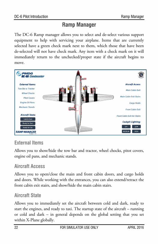
Ramp Manager
The DC-6 Ramp manager allows you to select and de-select various support equipment to help with servicing your airplane. Items that are currently selected have a green check mark next to them, which those that have been de-selected will not have check mark. Any item with a check mark on it will immediately return to the unchecked/proper state if the aircraft begins to move.
External Items Allows you to show/hide the tow bar and tractor, wheel chocks, pitot covers, engine oil pans, and mechanic stands.
Aircraft Access Allows you to open/close the main and front cabin doors, and cargo holds and doors. While working with the entrances, you can also extend/retract the front cabin exit stairs, and show/hide the main cabin stairs.
Aircraft State Allows you to immediately set the aircraft between cold and dark, ready to start the engines, and ready to taxi. The startup state of the aircraft – running or cold and dark – in general depends on the global setting that you set within X-Plane globally.
22 FOR SIMULATOR USE ONLY APRIL 2016
Ramp Manager DC-6 Pilot Introduction
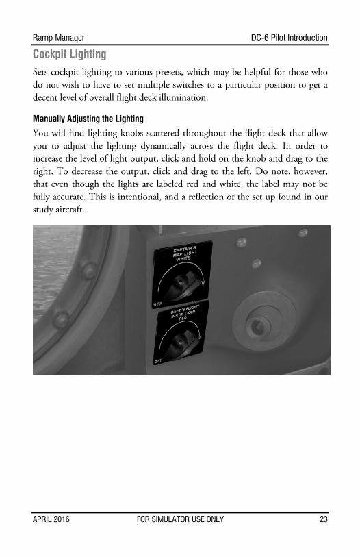
Cockpit Lighting Sets cockpit lighting to various presets, which may be helpful for those who do not wish to have to set multiple switches to a particular position to get a decent level of overall flight deck illumination.
Manually Adjusting the Lighting
You will find lighting knobs scattered throughout the flight deck that allow you to adjust the lighting dynamically across the flight deck. In order to increase the level of light output, click and hold on the knob and drag to the right. To decrease the output, click and drag to the left. Do note, however, that even though the lights are labeled red and white, the label may not be fully accurate. This is intentional, and a reflection of the set up found in our study aircraft.
APRIL 2016 FOR SIMULATOR USE ONLY 23

DC-6 Pilot Introduction Artificial Flight Engineer
Artificial Flight Engineer
Since the DC-6 is normally flown with a three person flight crew and the simulator is usually only flown by a single person, we have provided you with an Artificial Flight Engineer (AFE) to help you manage everything that is going on. The AFE can be controlled by clicking on the Flight Engineer side bar icon. The list of buttons allows you to select a particular checklist to be run. This will cause the Captain and/or AFE to run through the corresponding checklist. If it is set correctly, the AFE will confirm it. If it is not set correctly, the AFE will accomplish the action for you in many cases, with the notable exception being your manipulation (taxiing/flying) of the aircraft. In other words, certain parts of the checklist are prompted by the aircraft reaching a particular speed on departure. For example, you will need to accelerate to a specific speed prior to the AFE retracting the flaps or setting climb power. In order to abort a checklist for whatever reason, you can click the Abort button, after which you will need to manage all operations on your own.
In addition to running checklists and configuring the aircraft, the AFE also has the ability to monitor and maintain engine parameters. This includes engine manifold pressure, propeller RPM, and carburetor heat. If anything disturbs the aircraft in flight, such as a weather update in the sim, the AFE will adjust the throttle, propeller control, or carburetor heat to accommodate that change. The AFE will also continuously adjust the throttle to maintain proper climb power as the aircraft ascends. If you would prefer to manage this on your own, simply click the Abort button.
As a final item, the bottom of the AFE interface allows you to see the current workflow, and what actions are taking place. This is particularly useful when getting used to the AFE.
24 FOR SIMULATOR USE ONLY APRIL 2016
Maintenance Manager DC-6 Pilot Introduction
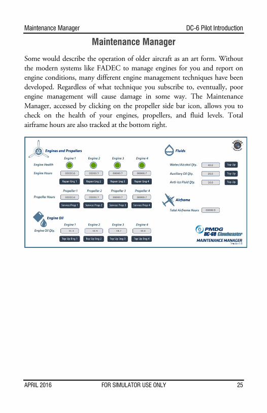
Maintenance Manager
Some would describe the operation of older aircraft as an art form. Without the modern systems like FADEC to manage engines for you and report on engine conditions, many different engine management techniques have been developed. Regardless of what technique you subscribe to, eventually, poor engine management will cause damage in some way. The Maintenance Manager, accessed by clicking on the propeller side bar icon, allows you to check on the health of your engines, propellers, and fluid levels. Total airframe hours are also tracked at the bottom right.
APRIL 2016 FOR SIMULATOR USE ONLY 25
DC-6 Pilot Introduction The Realism Options
The Realism Options
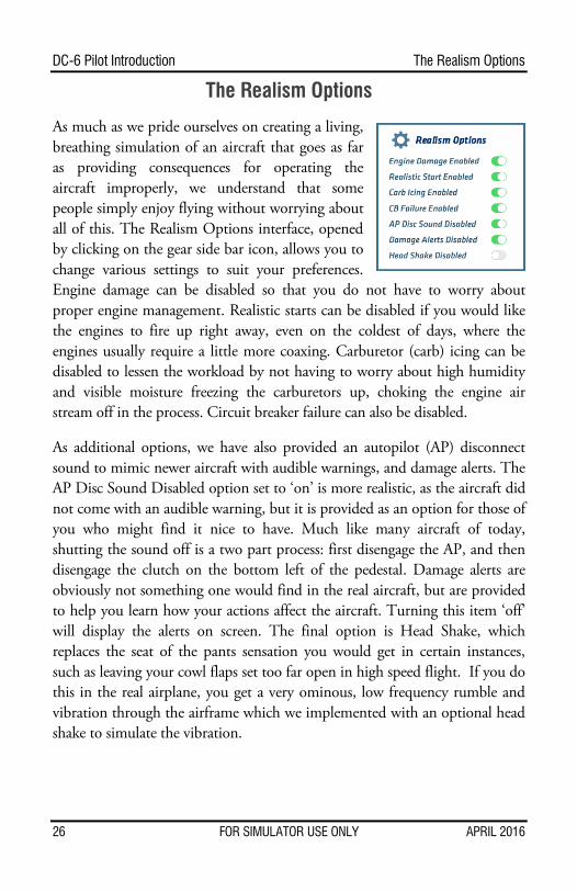
As much as we pride ourselves on creating a living, breathing simulation of an aircraft that goes as far as providing consequences for operating the aircraft improperly, we understand that some people simply enjoy flying without worrying about all of this. The Realism Options interface, opened by clicking on the gear side bar icon, allows you to change various settings to suit your preferences. Engine damage can be disabled so that you do not have to worry about proper engine management. Realistic starts can be disabled if you would like the engines to fire up right away, even on the coldest of days, where the engines usually require a little more coaxing. Carburetor (carb) icing can be disabled to lessen the workload by not having to worry about high humidity and visible moisture freezing the carburetors up, choking the engine air stream off in the process. Circuit breaker failure can also be disabled.
As additional options, we have also provided an autopilot (AP) disconnect sound to mimic newer aircraft with audible warnings, and damage alerts. The AP Disc Sound Disabled option set to ‘on’ is more realistic, as the aircraft did not come with an audible warning, but it is provided as an option for those of you who might find it nice to have. Much like many aircraft of today, shutting the sound off is a two part process: first disengage the AP, and then disengage the clutch on the bottom left of the pedestal. Damage alerts are obviously not something one would find in the real aircraft, but are provided to help you learn how your actions affect the aircraft. Turning this item ‘off’ will display the alerts on screen. The final option is Head Shake, which replaces the seat of the pants sensation you would get in certain instances, such as leaving your cowl flaps set too far open in high speed flight. If you do this in the real airplane, you get a very ominous, low frequency rumble and vibration through the airframe which we implemented with an optional head shake to simulate the vibration.
26 FOR SIMULATOR USE ONLY APRIL 2016
The Scenario Manager DC-6 Pilot Introduction
The Scenario Manager
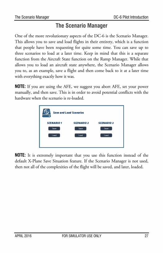
One of the more revolutionary aspects of the DC-6 is the Scenario Manager. This allows you to save and load flights in their entirety, which is a function that people have been requesting for quite some time. You can save up to three scenarios to load at a later time. Keep in mind that this is a separate function from the Aircraft State function on the Ramp Manager. While that allows you to load an aircraft state anywhere, the Scenario Manager allows you to, as an example, save a flight and then come back to it at a later time with everything exactly how it was.
NOTE: If you are using the AFE, we suggest you abort AFE, set your power manually, and then save. This is in order to avoid potential conflicts with the hardware when the scenario is re-loaded.
NOTE: It is extremely important that you use this function instead of the default X-Plane Save Situation feature. If the Scenario Manager is not used, then not all of the complexities of the flight will be saved, and later, loaded.
APRIL 2016 FOR SIMULATOR USE ONLY 27
DC-6 Pilot Introduction Flight Deck Operations
Flight Deck Operations
Captain Side Panel DME
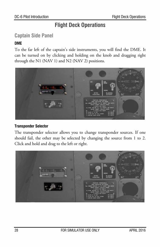
To the far left of the captain’s side instruments, you will find the DME. It can be turned on by clicking and holding on the knob and dragging right through the N1 (NAV 1) and N2 (NAV 2) positions.
Transponder Selector
The transponder selector allows you to change transponder sources. If one should fail, the other may be selected by changing the source from 1 to 2. Click and hold and drag to the left or right.
28 FOR SIMULATOR USE ONLY APRIL 2016
Flight Deck Operations DC-6 Pilot Introduction
Gyro Slaving
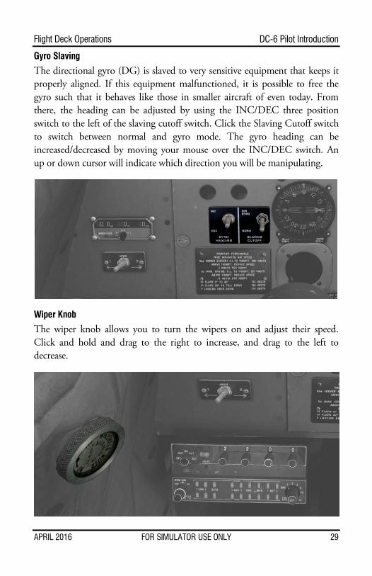
The directional gyro (DG) is slaved to very sensitive equipment that keeps it properly aligned. If this equipment malfunctioned, it is possible to free the gyro such that it behaves like those in smaller aircraft of even today. From there, the heading can be adjusted by using the INC/DEC three position switch to the left of the slaving cutoff switch. Click the Slaving Cutoff switch to switch between normal and gyro mode. The gyro heading can be increased/decreased by moving your mouse over the INC/DEC switch. An up or down cursor will indicate which direction you will be manipulating.
Wiper Knob
The wiper knob allows you to turn the wipers on and adjust their speed. Click and hold and drag to the right to increase, and drag to the left to decrease.
APRIL 2016 FOR SIMULATOR USE ONLY 29
DC-6 Pilot Introduction Flight Deck Operations
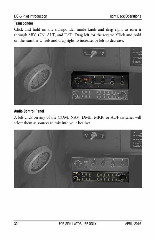
Transponder
Click and hold on the transponder mode knob and drag right to turn it through SBY, ON, ALT, and TST. Drag left for the reverse. Click and hold on the number wheels and drag right to increase, or left to decrease.
Audio Control Panel
A left click on any of the COM, NAV, DME, MKR, or ADF switches will select them as sources to mix into your headset.
30 FOR SIMULATOR USE ONLY APRIL 2016
Flight Deck Operations DC-6 Pilot Introduction
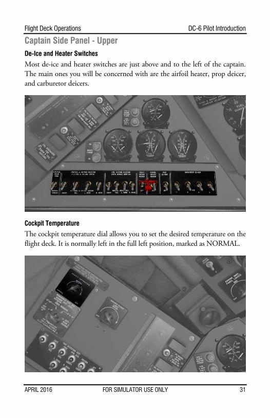
Captain Side Panel - Upper De-Ice and Heater Switches
Most de-ice and heater switches are just above and to the left of the captain. The main ones you will be concerned with are the airfoil heater, prop deicer, and carburetor deicers.
Cockpit Temperature
The cockpit temperature dial allows you to set the desired temperature on the flight deck. It is normally left in the full left position, marked as NORMAL.
APRIL 2016 FOR SIMULATOR USE ONLY 31
DC-6 Pilot Introduction Flight Deck Operations
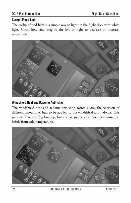
Cockpit Flood Light
The cockpit flood light is a simple way to light up the flight deck with white light. Click, hold and drag to the left or right to decrease or increase, respectively.
Windshield Heat and Radome Anti-icing
The windshield heat and radome anti-icing switch allows the selection of different amounts of heat to be applied to the windshield and radome. This prevents frost and fog buildup, but also keeps the areas from becoming too brittle from cold temperatures.
32 FOR SIMULATOR USE ONLY APRIL 2016
Flight Deck Operations DC-6 Pilot Introduction
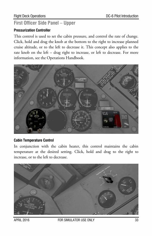
First Officer Side Panel – Upper Pressurization Controller
This control is used to set the cabin pressure, and control the rate of change. Click, hold and drag the knob at the bottom to the right to increase planned cruise altitude, or to the left to decrease it. This concept also applies to the rate knob on the left – drag right to increase, or left to decrease. For more information, see the Operations Handbook.
Cabin Temperature Control
In conjunction with the cabin heater, this control maintains the cabin temperature at the desired setting. Click, hold and drag to the right to increase, or to the left to decrease.
APRIL 2016 FOR SIMULATOR USE ONLY 33
DC-6 Pilot Introduction Flight Deck Operations
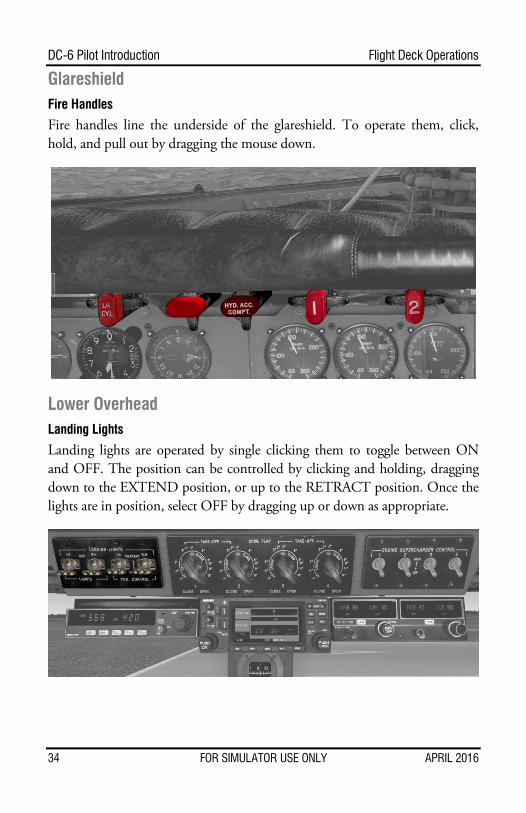
Glareshield Fire Handles
Fire handles line the underside of the glareshield. To operate them, click, hold, and pull out by dragging the mouse down.
Lower Overhead Landing Lights
Landing lights are operated by single clicking them to toggle between ON and OFF. The position can be controlled by clicking and holding, dragging down to the EXTEND position, or up to the RETRACT position. Once the lights are in position, select OFF by dragging up or down as appropriate.
34 FOR SIMULATOR USE ONLY APRIL 2016
Flight Deck Operations DC-6 Pilot Introduction
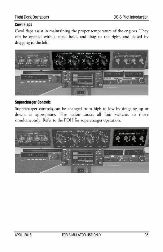
Cowl Flaps
Cowl flaps assist in maintaining the proper temperature of the engines. They can be opened with a click, hold, and drag to the right, and closed by dragging to the left.
Supercharger Controls
Supercharger controls can be changed from high to low by dragging up or down, as appropriate. The action causes all four switches to move simultaneously. Refer to the POH for supercharger operation.
APRIL 2016 FOR SIMULATOR USE ONLY 35
DC-6 Pilot Introduction Flight Deck Operations
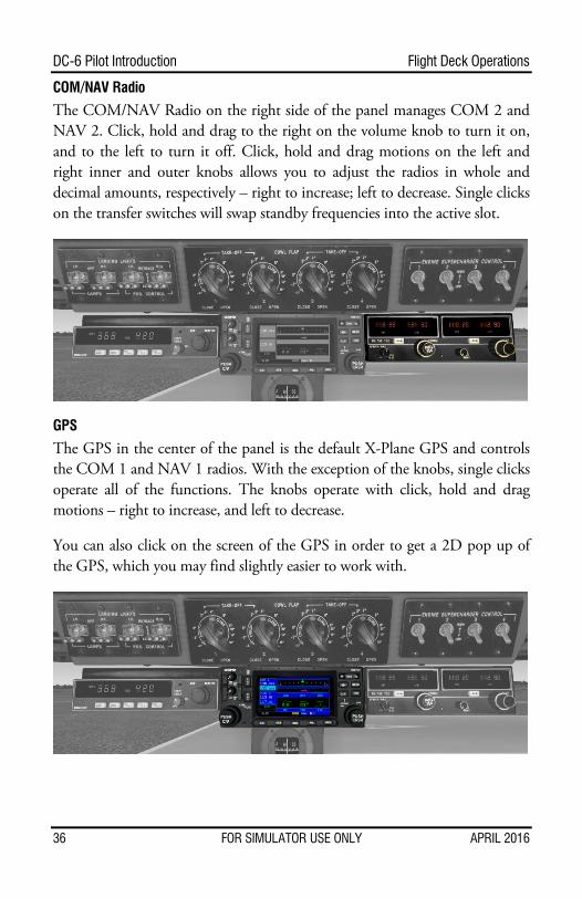
COM/NAV Radio
The COM/NAV Radio on the right side of the panel manages COM 2 and NAV 2. Click, hold and drag to the right on the volume knob to turn it on, and to the left to turn it off. Click, hold and drag motions on the left and right inner and outer knobs allows you to adjust the radios in whole and decimal amounts, respectively – right to increase; left to decrease. Single clicks on the transfer switches will swap standby frequencies into the active slot.
GPS
The GPS in the center of the panel is the default X-Plane GPS and controls the COM 1 and NAV 1 radios. With the exception of the knobs, single clicks operate all of the functions. The knobs operate with click, hold and drag motions – right to increase, and left to decrease.
You can also click on the screen of the GPS in order to get a 2D pop up of the GPS, which you may find slightly easier to work with.
36 FOR SIMULATOR USE ONLY APRIL 2016
Flight Deck Operations DC-6 Pilot Introduction
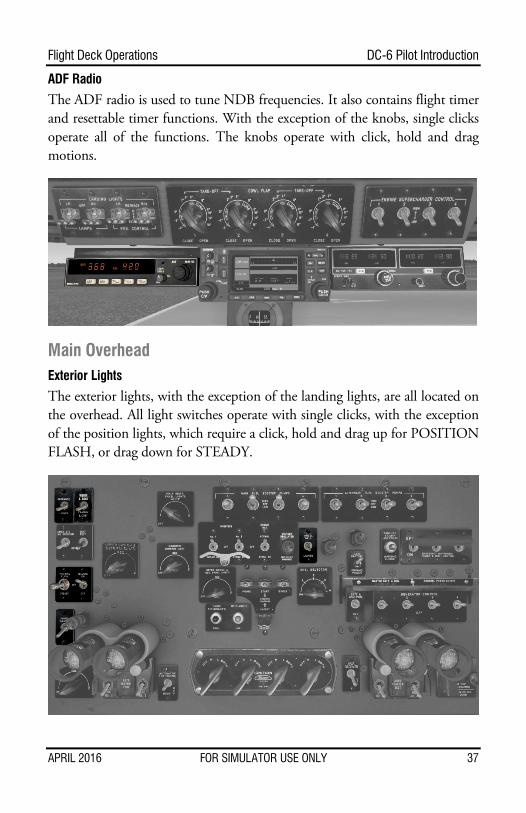
ADF Radio
The ADF radio is used to tune NDB frequencies. It also contains flight timer and resettable timer functions. With the exception of the knobs, single clicks operate all of the functions. The knobs operate with click, hold and drag motions.
Main Overhead Exterior Lights
The exterior lights, with the exception of the landing lights, are all located on the overhead. All light switches operate with single clicks, with the exception of the position lights, which require a click, hold and drag up for POSITION FLASH, or drag down for STEADY.
APRIL 2016 FOR SIMULATOR USE ONLY 37
DC-6 Pilot Introduction Flight Deck Operations
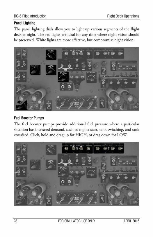
Panel Lighting
The panel lighting dials allow you to light up various segments of the flight deck at night. The red lights are ideal for any time where night vision should be preserved. White lights are more effective, but compromise night vision.
Fuel Booster Pumps
The fuel booster pumps provide additional fuel pressure where a particular situation has increased demand, such as engine start, tank switching, and tank crossfeed. Click, hold and drag up for HIGH, or drag down for LOW.
38 FOR SIMULATOR USE ONLY APRIL 2016
Flight Deck Operations DC-6 Pilot Introduction
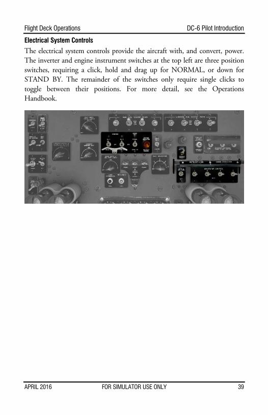
Electrical System Controls
The electrical system controls provide the aircraft with, and convert, power. The inverter and engine instrument switches at the top left are three position switches, requiring a click, hold and drag up for NORMAL, or down for STAND BY. The remainder of the switches only require single clicks to toggle between their positions. For more detail, see the Operations Handbook.
APRIL 2016 FOR SIMULATOR USE ONLY 39

DC-6 Pilot Introduction Flight Deck Operations
Engine Starter Controls and Magnetos
The engine starter controls and magnetos allow you to start, and sustain an engine, in combination with the mixture levers on the pedestal. The starter requires a single click and will remain in position while the engine starts. The engine selector and magneto switches require a click, hold and drag to the right to increase the selection, or drag to the left to decrease the selection.
Passenger Signs and Call Buttons
The passenger signs switches allow you to illuminate the signs in the cabin corresponding with the requirement to refrain from smoking, or to wear a seat belt. The call buttons call the listed station.
40 FOR SIMULATOR USE ONLY APRIL 2016
Flight Deck Operations DC-6 Pilot Introduction
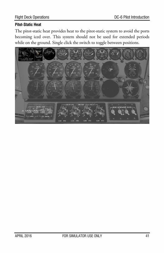
Pitot-Static Heat
The pitot-static heat provides heat to the pitot-static system to avoid the ports becoming iced over. This system should not be used for extended periods while on the ground. Single click the switch to toggle between positions.
APRIL 2016 FOR SIMULATOR USE ONLY 41
DC-6 Pilot Introduction Flight Deck Operations
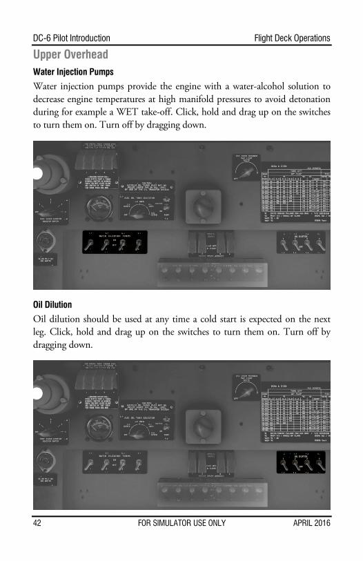
Upper Overhead Water Injection Pumps
Water injection pumps provide the engine with a water-alcohol solution to decrease engine temperatures at high manifold pressures to avoid detonation during for example a WET take-off. Click, hold and drag up on the switches to turn them on. Turn off by dragging down.
Oil Dilution
Oil dilution should be used at any time a cold start is expected on the next leg. Click, hold and drag up on the switches to turn them on. Turn off by dragging down.
42 FOR SIMULATOR USE ONLY APRIL 2016
Flight Deck Operations DC-6 Pilot Introduction
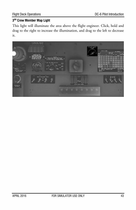
3RD Crew Member Map Light
This light will illuminate the area above the flight engineer. Click, hold and drag to the right to increase the illumination, and drag to the left to decrease it.
APRIL 2016 FOR SIMULATOR USE ONLY 43
DC-6 Pilot Introduction Flight Deck Operations
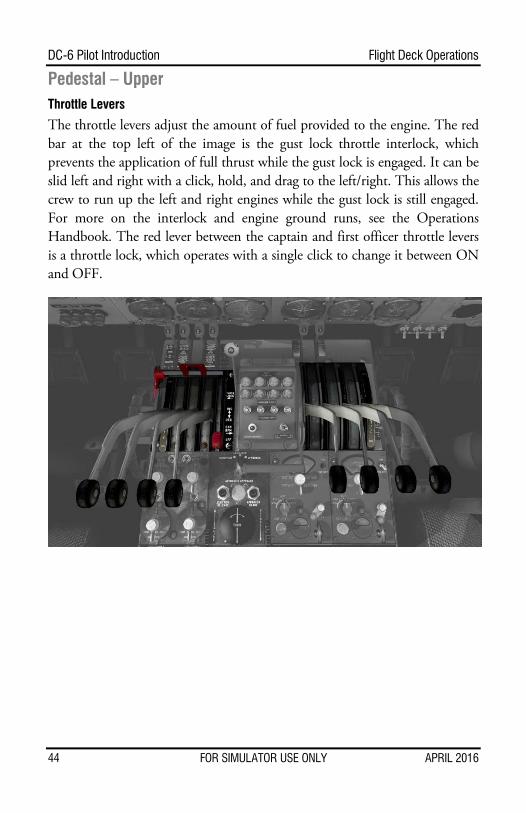
Pedestal – Upper Throttle Levers
The throttle levers adjust the amount of fuel provided to the engine. The red bar at the top left of the image is the gust lock throttle interlock, which prevents the application of full thrust while the gust lock is engaged. It can be slid left and right with a click, hold, and drag to the left/right. This allows the crew to run up the left and right engines while the gust lock is still engaged. For more on the interlock and engine ground runs, see the Operations Handbook. The red lever between the captain and first officer throttle levers is a throttle lock, which operates with a single click to change it between ON and OFF.
44 FOR SIMULATOR USE ONLY APRIL 2016

Flight Deck Operations DC-6 Pilot Introduction
RPM Controls
Unlike many aircraft you may be used to, the RPM of all of the engines is controlled with a single prop control, which is on the left side of the highlighted area in the image, marked with ‘P’. A click, hold and drag forward increases RPM, while dragging rearward decreases it. In order to change individual RPM, change the slave switch at the bottom right of the highlighted area to MANUAL with a click, hold and drag to the left or right to its center position. From there, use the toggle switch for the appropriate engine to adjust the RPM. Holding your cursor over the switch will show an up or down arrow. Click and hold while this is displayed to adjust the RPM up or down, as indicated by the arrow cursor. The RPM can also be resynchronized with a single click of the RESYNCHRONIZE button. Note that the PROP REVERSE bar is in the REVERSE position to show the RESYNCHRONIZE and slave switch. Single click it to toggle between NORMAL and REVERSE positions, though we suggest setting up a hardware button. See Setting Custom View Points
X-Plane has a rather robust camera system that allows you to move around with relative ease. The arrow keys allow you to move left, right, up, and down. The Page Up and Page Down keys move you forward and aft. Of course, the plus and minus keys adjust the zoom.
The true power of the function, though, is the ability to very quickly save any view that you have positioned. If you like a particular view, simply press CTRL and then tap a number on the number pad of your keyboard. Later on, to recall this view, simply tap the number key that you assigned. Note that you can save a few views on the flight deck, and then switch into external view and save a few external views as well.
We recommend saving the default view to a particular number, such as 0, so that you may always recall the default position quickly. Pressing the number key a second time will return you to the previous view, as well.
APRIL 2016 FOR SIMULATOR USE ONLY 45
DC-6 Pilot Introduction Flight Deck Operations
Setting Custom Hardware Commands on page 54.
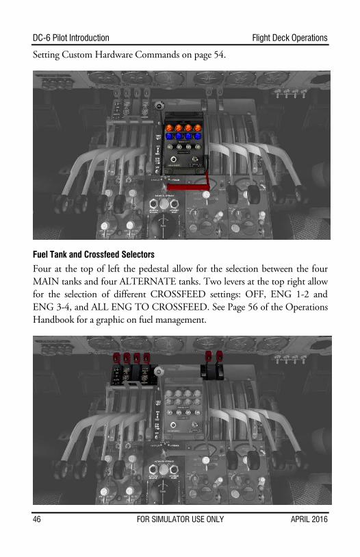
Fuel Tank and Crossfeed Selectors
Four at the top of left the pedestal allow for the selection between the four MAIN tanks and four ALTERNATE tanks. Two levers at the top right allow for the selection of different CROSSFEED settings: OFF, ENG 1-2 and ENG 3-4, and ALL ENG TO CROSSFEED. See Page 56 of the Operations Handbook for a graphic on fuel management.
46 FOR SIMULATOR USE ONLY APRIL 2016
Flight Deck Operations DC-6 Pilot Introduction
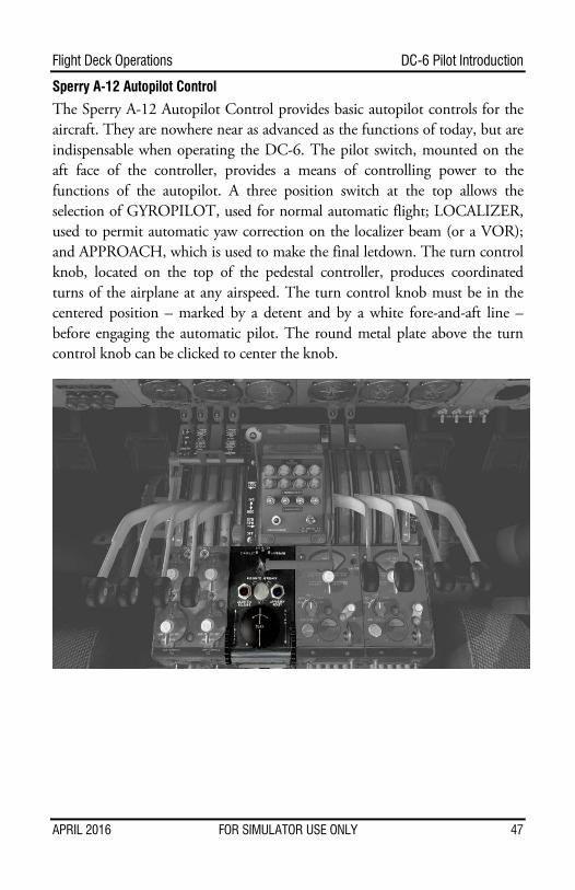
Sperry A-12 Autopilot Control
The Sperry A-12 Autopilot Control provides basic autopilot controls for the aircraft. They are nowhere near as advanced as the functions of today, but are indispensable when operating the DC-6. The pilot switch, mounted on the aft face of the controller, provides a means of controlling power to the functions of the autopilot. A three position switch at the top allows the selection of GYROPILOT, used for normal automatic flight; LOCALIZER, used to permit automatic yaw correction on the localizer beam (or a VOR); and APPROACH, which is used to make the final letdown. The turn control knob, located on the top of the pedestal controller, produces coordinated turns of the airplane at any airspeed. The turn control knob must be in the centered position – marked by a detent and by a white fore-and-aft line – before engaging the automatic pilot. The round metal plate above the turn control knob can be clicked to center the knob.
APRIL 2016 FOR SIMULATOR USE ONLY 47
DC-6 Pilot Introduction Flight Deck Operations
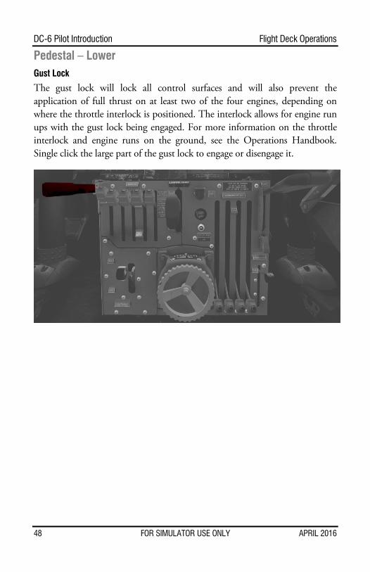
Pedestal – Lower Gust Lock
The gust lock will lock all control surfaces and will also prevent the application of full thrust on at least two of the four engines, depending on where the throttle interlock is positioned. The interlock allows for engine run ups with the gust lock being engaged. For more information on the throttle interlock and engine runs on the ground, see the Operations Handbook. Single click the large part of the gust lock to engage or disengage it.
48 FOR SIMULATOR USE ONLY APRIL 2016
Flight Deck Operations DC-6 Pilot Introduction
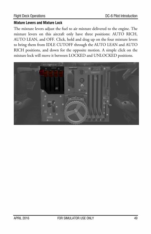
Mixture Levers and Mixture Lock
The mixture levers adjust the fuel to air mixture delivered to the engine. The mixture levers on this aircraft only have three positions: AUTO RICH, AUTO LEAN, and OFF. Click, hold and drag up on the four mixture levers to bring them from IDLE CUTOFF through the AUTO LEAN and AUTO RICH positions, and down for the opposite motion. A simple click on the mixture lock will move it between LOCKED and UNLOCKED positions.
APRIL 2016 FOR SIMULATOR USE ONLY 49
DC-6 Pilot Introduction Flight Deck Operations
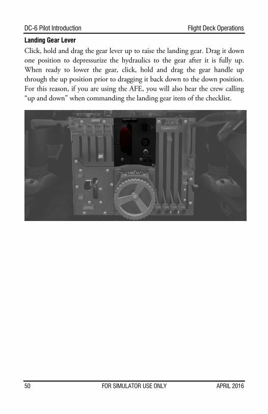
Landing Gear Lever
Click, hold and drag the gear lever up to raise the landing gear. Drag it down one position to depressurize the hydraulics to the gear after it is fully up. When ready to lower the gear, click, hold and drag the gear handle up through the up position prior to dragging it back down to the down position. For this reason, if you are using the AFE, you will also hear the crew calling “up and down” when commanding the landing gear item of the checklist.
50 FOR SIMULATOR USE ONLY APRIL 2016
Flight Deck Operations DC-6 Pilot Introduction
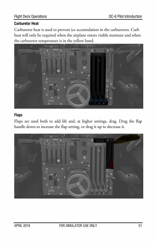
Carburetor Heat
Carburetor heat is used to prevent ice accumulation in the carburetors. Carb heat will only be required when the airplane enters visible moisture and when the carburetor temperature is in the yellow band.
Flaps
Flaps are used both to add lift and, at higher settings, drag. Drag the flap handle down to increase the flap setting, or drag it up to decrease it.
APRIL 2016 FOR SIMULATOR USE ONLY 51
DC-6 Pilot Introduction Flight Deck Operations
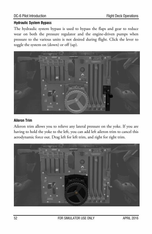
Hydraulic System Bypass
The hydraulic system bypass is used to bypass the flaps and gear to reduce wear on both the pressure regulator and the engine-driven pumps when pressure to the various units is not desired during flight. Click the lever to toggle the system on (down) or off (up).
Aileron Trim
Aileron trim allows you to relieve any lateral pressure on the yoke. If you are having to hold the yoke to the left, you can add left aileron trim to cancel this aerodynamic force out. Drag left for left trim, and right for right trim.
52 FOR SIMULATOR USE ONLY APRIL 2016
Flight Deck Operations DC-6 Pilot Introduction
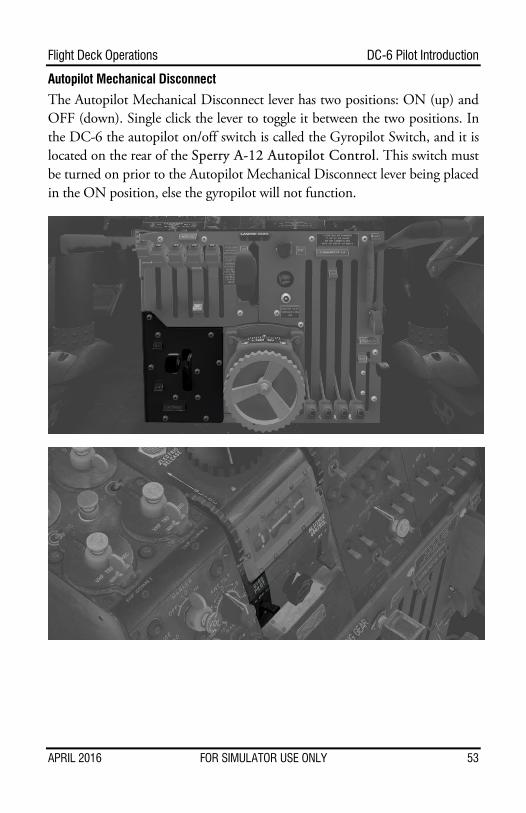
Autopilot Mechanical Disconnect
The Autopilot Mechanical Disconnect lever has two positions: ON (up) and OFF (down). Single click the lever to toggle it between the two positions. In the DC-6 the autopilot on/off switch is called the Gyropilot Switch, and it is located on the rear of the Sperry A-12 Autopilot Control. This switch must be turned on prior to the Autopilot Mechanical Disconnect lever being placed in the ON position, else the gyropilot will not function.
APRIL 2016 FOR SIMULATOR USE ONLY 53
DC-6 Pilot Introduction Setting Custom View Points
Setting Custom View Points
X-Plane has a rather robust camera system that allows you to move around with relative ease. The arrow keys allow you to move left, right, up, and down. The Page Up and Page Down keys move you forward and aft. Of course, the plus and minus keys adjust the zoom.
The true power of the function, though, is the ability to very quickly save any view that you have positioned. If you like a particular view, simply press CTRL and then tap a number on the number pad of your keyboard. Later on, to recall this view, simply tap the number key that you assigned. Note that you can save a few views on the flight deck, and then switch into external view and save a few external views as well.
We recommend saving the default view to a particular number, such as 0, so that you may always recall the default position quickly. Pressing the number key a second time will return you to the previous view, as well.
54 FOR SIMULATOR USE ONLY APRIL 2016
Setting Custom Hardware Commands DC-6 Pilot Introduction
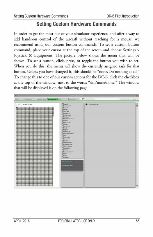
Setting Custom Hardware Commands
In order to get the most out of your simulator experience, and offer a way to add hands-on control of the aircraft without reaching for a mouse, we recommend using our custom button commands. To set a custom button command, place your cursor at the top of the screen and choose Settings > Joystick & Equipment. The picture below shows the menu that will be shown. To set a button, click, press, or toggle the button you wish to set. When you do this, the menu will show the currently assigned task for that button. Unless you have changed it, this should be “none/Do nothing at all!” To change this to one of our custom actions for the DC-6, click the checkbox at the top of the window, next to the words “sim/none/none.” The window that will be displayed is on the following page.
APRIL 2016 FOR SIMULATOR USE ONLY 55
DC-6 Pilot Introduction Setting Custom Hardware Commands
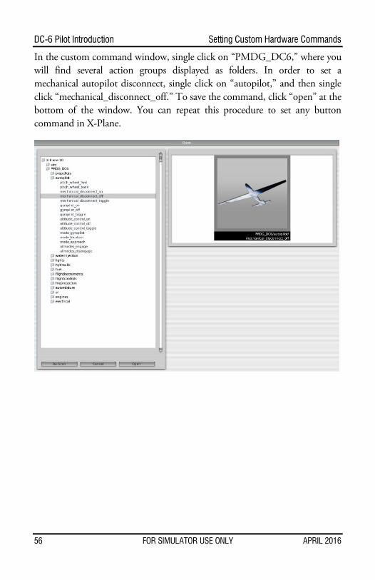
In the custom command window, single click on “PMDG_DC6,” where you will find several action groups displayed as folders. In order to set a mechanical autopilot disconnect, single click on “autopilot,” and then single click “mechanical_disconnect_off.” To save the command, click “open” at the bottom of the window. You can repeat this procedure to set any button command in X-Plane.
56 FOR SIMULATOR USE ONLY APRIL 2016