dc arc welding power source january, 2005 · contact with hot engine parts and igniting. do not...
TRANSCRIPT
OPERATOR’S MANUAL
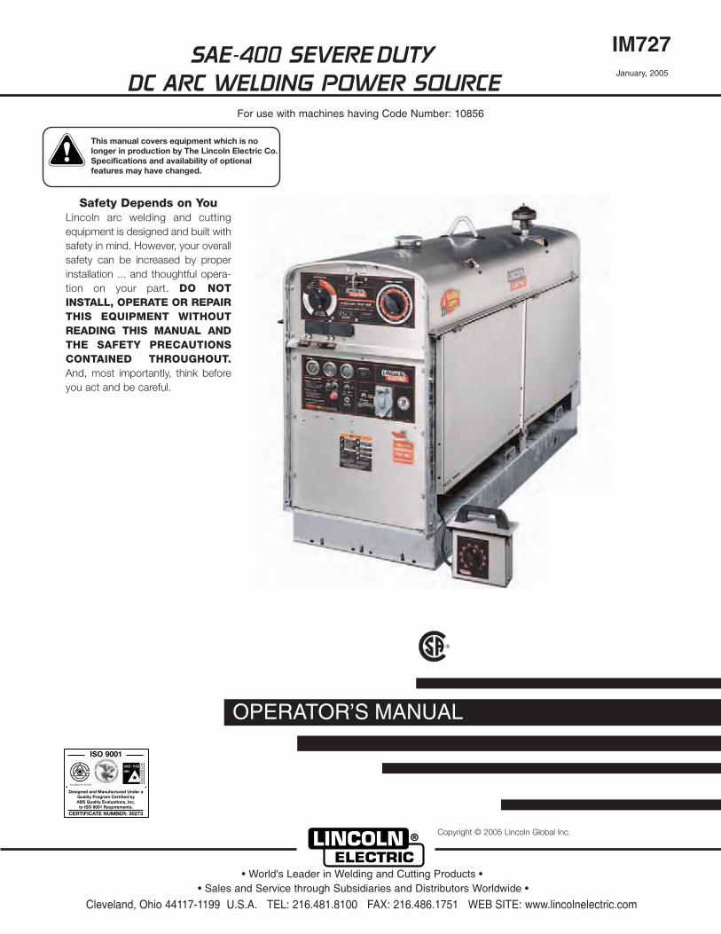
SAE-400 SEVERE DUTYDC ARC WELDING POWER SOURCE
IM727January, 2005
For use with machines having Code Number: 10856
Safety Depends on YouLincoln arc welding and cuttingequipment is designed and built withsafety in mind. However, your overallsafety can be increased by properinstallation ... and thoughtful opera-tion on your part. DO NOTINSTALL, OPERATE OR REPAIRTHIS EQUIPMENT WITHOUTREADING THIS MANUAL ANDTHE SAFETY PRECAUTIONSCONTAINED THROUGHOUT.And, most importantly, think beforeyou act and be careful.
R
• Sales and Service through Subsidiaries and Distributors Worldwide •
Cleveland, Ohio 44117-1199 U.S.A. TEL: 216.481.8100 FAX: 216.486.1751 WEB SITE: www.lincolnelectric.com
• World's Leader in Welding and Cutting Products •
Copyright © 2005 Lincoln Global Inc.
This manual covers equipment which is no longer in production by The Lincoln Electric Co. Speci�cations and availability of optional features may have changed.
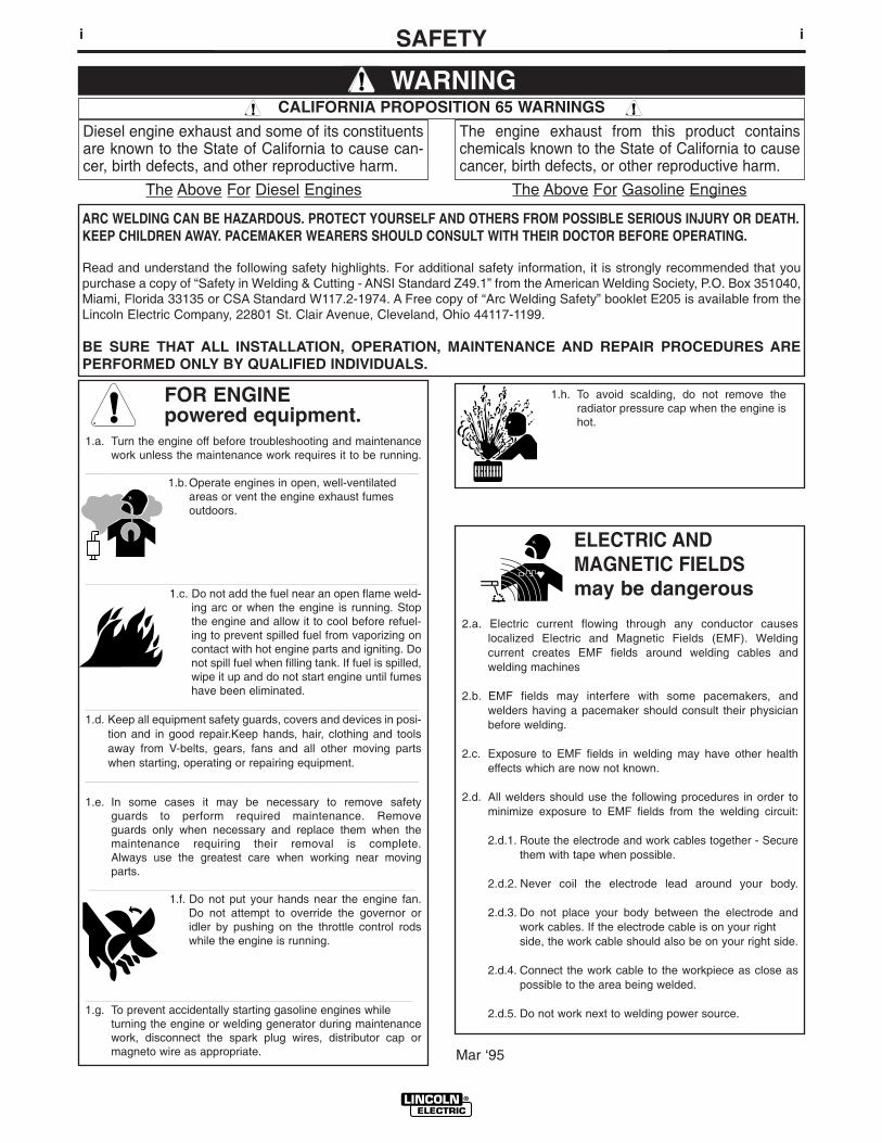
FOR ENGINEpowered equipment.
1.a. Turn the engine off before troubleshooting and maintenancework unless the maintenance work requires it to be running.
____________________________________________________1.b. Operate engines in open, well-ventilated
areas or vent the engine exhaust fumes outdoors.
____________________________________________________1.c. Do not add the fuel near an open flame weld-
ing arc or when the engine is running. Stopthe engine and allow it to cool before refuel-ing to prevent spilled fuel from vaporizing oncontact with hot engine parts and igniting. Donot spill fuel when filling tank. If fuel is spilled,wipe it up and do not start engine until fumeshave been eliminated.
____________________________________________________1.d. Keep all equipment safety guards, covers and devices in posi-
tion and in good repair.Keep hands, hair, clothing and toolsaway from V-belts, gears, fans and all other moving partswhen starting, operating or repairing equipment.
____________________________________________________
1.e. In some cases it may be necessary to remove safetyguards to perform required maintenance. Removeguards only when necessary and replace them when themaintenance requiring their removal is complete.Always use the greatest care when working near movingparts.
___________________________________________________1.f. Do not put your hands near the engine fan.
Do not attempt to override the governor oridler by pushing on the throttle control rodswhile the engine is running.
___________________________________________________1.g. To prevent accidentally starting gasoline engines while
turning the engine or welding generator during maintenancework, disconnect the spark plug wires, distributor cap ormagneto wire as appropriate.
iSAFETYi
ARC WELDING CAN BE HAZARDOUS. PROTECT YOURSELF AND OTHERS FROM POSSIBLE SERIOUS INJURY OR DEATH.KEEP CHILDREN AWAY. PACEMAKER WEARERS SHOULD CONSULT WITH THEIR DOCTOR BEFORE OPERATING.
Read and understand the following safety highlights. For additional safety information, it is strongly recommended that youpurchase a copy of “Safety in Welding & Cutting - ANSI Standard Z49.1” from the American Welding Society, P.O. Box 351040,Miami, Florida 33135 or CSA Standard W117.2-1974. A Free copy of “Arc Welding Safety” booklet E205 is available from theLincoln Electric Company, 22801 St. Clair Avenue, Cleveland, Ohio 44117-1199.
BE SURE THAT ALL INSTALLATION, OPERATION, MAINTENANCE AND REPAIR PROCEDURES AREPERFORMED ONLY BY QUALIFIED INDIVIDUALS.
WARNING
Mar ‘95
ELECTRIC AND MAGNETIC FIELDSmay be dangerous
2.a. Electric current flowing through any conductor causes localized Electric and Magnetic Fields (EMF). Welding current creates EMF fields around welding cables and welding machines
2.b. EMF fields may interfere with some pacemakers, andwelders having a pacemaker should consult their physicianbefore welding.
2.c. Exposure to EMF fields in welding may have other healtheffects which are now not known.
2.d. All welders should use the following procedures in order tominimize exposure to EMF fields from the welding circuit:
2.d.1. Route the electrode and work cables together - Securethem with tape when possible.
2.d.2. Never coil the electrode lead around your body.
2.d.3. Do not place your body between the electrode andwork cables. If the electrode cable is on your right side, the work cable should also be on your right side.
2.d.4. Connect the work cable to the workpiece as close aspossible to the area being welded.
2.d.5. Do not work next to welding power source.
1.h. To avoid scalding, do not remove theradiator pressure cap when the engine ishot.
CALIFORNIA PROPOSITION 65 WARNINGS
Diesel engine exhaust and some of its constituentsare known to the State of California to cause can-cer, birth defects, and other reproductive harm.
The engine exhaust from this product containschemicals known to the State of California to causecancer, birth defects, or other reproductive harm.
The Above For Diesel Engines The Above For Gasoline Engines
iiSAFETYii
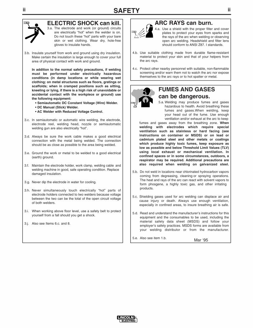
ARC RAYS can burn.4.a. Use a shield with the proper filter and cover
plates to protect your eyes from sparks andthe rays of the arc when welding or observingopen arc welding. Headshield and filter lensshould conform to ANSI Z87. I standards.
4.b. Use suitable clothing made from durable flame-resistantmaterial to protect your skin and that of your helpers fromthe arc rays.
4.c. Protect other nearby personnel with suitable, non-flammablescreening and/or warn them not to watch the arc nor exposethemselves to the arc rays or to hot spatter or metal.
ELECTRIC SHOCK can kill.3.a. The electrode and work (or ground) circuits
are electrically “hot” when the welder is on.Do not touch these “hot” parts with your bareskin or wet clothing. Wear dry, hole-freegloves to insulate hands.
3.b. Insulate yourself from work and ground using dry insulation.Make certain the insulation is large enough to cover your fullarea of physical contact with work and ground.
In addition to the normal safety precautions, if weldingmust be performed under electrically hazardousconditions (in damp locations or while wearing wetclothing; on metal structures such as floors, gratings orscaffolds; when in cramped positions such as sitting,kneeling or lying, if there is a high risk of unavoidable oraccidental contact with the workpiece or ground) usethe following equipment:
• Semiautomatic DC Constant Voltage (Wire) Welder.• DC Manual (Stick) Welder.• AC Welder with Reduced Voltage Control.
3.c. In semiautomatic or automatic wire welding, the electrode,electrode reel, welding head, nozzle or semiautomaticwelding gun are also electrically “hot”.
3.d. Always be sure the work cable makes a good electricalconnection with the metal being welded. The connectionshould be as close as possible to the area being welded.
3.e. Ground the work or metal to be welded to a good electrical(earth) ground.
3.f. Maintain the electrode holder, work clamp, welding cable andwelding machine in good, safe operating condition. Replacedamaged insulation.
3.g. Never dip the electrode in water for cooling.
3.h. Never simultaneously touch electrically “hot” parts ofelectrode holders connected to two welders because voltagebetween the two can be the total of the open circuit voltageof both welders.
3.i. When working above floor level, use a safety belt to protectyourself from a fall should you get a shock.
3.j. Also see Items 6.c. and 8.
FUMES AND GASEScan be dangerous.5.a. Welding may produce fumes and gases
hazardous to health. Avoid breathing thesefumes and gases.When welding, keepyour head out of the fume. Use enoughventilation and/or exhaust at the arc to keep
fumes and gases away from the breathing zone. Whenwelding with electrodes which require specialventilation such as stainless or hard facing (seeinstructions on container or MSDS) or on lead orcadmium plated steel and other metals or coatingswhich produce highly toxic fumes, keep exposure aslow as possible and below Threshold Limit Values (TLV)using local exhaust or mechanical ventilation. Inconfined spaces or in some circumstances, outdoors, arespirator may be required. Additional precautions arealso required when welding on galvanized steel.
5.b. Do not weld in locations near chlorinated hydrocarbon vaporscoming from degreasing, cleaning or spraying operations.The heat and rays of the arc can react with solvent vapors toform phosgene, a highly toxic gas, and other irritating products.
5.c. Shielding gases used for arc welding can displace air andcause injury or death. Always use enough ventilation,especially in confined areas, to insure breathing air is safe.
5.d. Read and understand the manufacturer’s instructions for thisequipment and the consumables to be used, including thematerial safety data sheet (MSDS) and follow youremployer’s safety practices. MSDS forms are available fromyour welding distributor or from the manufacturer.
5.e. Also see item 1.b. Mar ‘95
iiiSAFETYiii
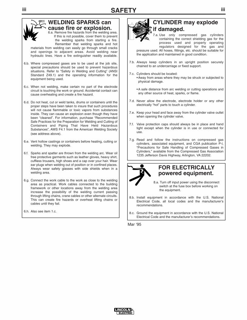
FOR ELECTRICALLYpowered equipment.
8.a. Turn off input power using the disconnectswitch at the fuse box before working onthe equipment.
8.b. Install equipment in accordance with the U.S. NationalElectrical Code, all local codes and the manufacturer’srecommendations.
8.c. Ground the equipment in accordance with the U.S. NationalElectrical Code and the manufacturer’s recommendations.
CYLINDER may explodeif damaged.7.a. Use only compressed gas cylinders
containing the correct shielding gas for theprocess used and properly operatingregulators designed for the gas and
pressure used. All hoses, fittings, etc. should be suitable forthe application and maintained in good condition.
7.b. Always keep cylinders in an upright position securelychained to an undercarriage or fixed support.
7.c. Cylinders should be located:• Away from areas where they may be struck or subjected tophysical damage.
• A safe distance from arc welding or cutting operations andany other source of heat, sparks, or flame.
7.d. Never allow the electrode, electrode holder or any otherelectrically “hot” parts to touch a cylinder.
7.e. Keep your head and face away from the cylinder valve outletwhen opening the cylinder valve.
7.f. Valve protection caps should always be in place and handtight except when the cylinder is in use or connected foruse.
7.g. Read and follow the instructions on compressed gascylinders, associated equipment, and CGA publication P-l,“Precautions for Safe Handling of Compressed Gases inCylinders,” available from the Compressed Gas Association1235 Jefferson Davis Highway, Arlington, VA 22202.
Mar ‘95
WELDING SPARKS cancause fire or explosion.6.a. Remove fire hazards from the welding area.
If this is not possible, cover them to preventthe welding sparks from starting a fire.Remember that welding sparks and hot
materials from welding can easily go through small cracksand openings to adjacent areas. Avoid welding nearhydraulic lines. Have a fire extinguisher readily available.
6.b. Where compressed gases are to be used at the job site,special precautions should be used to prevent hazardoussituations. Refer to “Safety in Welding and Cutting” (ANSIStandard Z49.1) and the operating information for theequipment being used.
6.c. When not welding, make certain no part of the electrodecircuit is touching the work or ground. Accidental contact cancause overheating and create a fire hazard.
6.d. Do not heat, cut or weld tanks, drums or containers until theproper steps have been taken to insure that such procedureswill not cause flammable or toxic vapors from substancesinside. They can cause an explosion even though they havebeen “cleaned”. For information, purchase “RecommendedSafe Practices for the Preparation for Welding and Cutting ofContainers and Piping That Have Held HazardousSubstances”, AWS F4.1 from the American Welding Society(see address above).
6.e. Vent hollow castings or containers before heating, cutting orwelding. They may explode.
6.f. Sparks and spatter are thrown from the welding arc. Wear oilfree protective garments such as leather gloves, heavy shirt,cuffless trousers, high shoes and a cap over your hair. Wearear plugs when welding out of position or in confined places.Always wear safety glasses with side shields when in awelding area.
6.g. Connect the work cable to the work as close to the weldingarea as practical. Work cables connected to the buildingframework or other locations away from the welding areaincrease the possibility of the welding current passingthrough lifting chains, crane cables or other alternate circuits.This can create fire hazards or overheat lifting chains orcables until they fail.
6.h. Also see item 1.c.
ivSAFETYiv
Mar. ‘93
PRÉCAUTIONS DE SÛRETÉPour votre propre protection lire et observer toutes les instructionset les précautions de sûreté specifiques qui parraissent dans cemanuel aussi bien que les précautions de sûreté générales suiv-antes:
Sûreté Pour Soudage A L’Arc1. Protegez-vous contre la secousse électrique:
a. Les circuits à l’électrode et à la piéce sont sous tensionquand la machine à souder est en marche. Eviter toujourstout contact entre les parties sous tension et la peau nueou les vétements mouillés. Porter des gants secs et sanstrous pour isoler les mains.
b. Faire trés attention de bien s’isoler de la masse quand onsoude dans des endroits humides, ou sur un plancher met-allique ou des grilles metalliques, principalement dans les positions assis ou couché pour lesquelles une grandepartie du corps peut être en contact avec la masse.
c. Maintenir le porte-électrode, la pince de masse, le câble desoudage et la machine à souder en bon et sûr état defonc-tionnement.
d.Ne jamais plonger le porte-électrode dans l’eau pour lerefroidir.
e. Ne jamais toucher simultanément les parties sous tensiondes porte-électrodes connectés à deux machines à soud-er parce que la tension entre les deux pinces peut être letotal de la tension à vide des deux machines.
f. Si on utilise la machine à souder comme une source decourant pour soudage semi-automatique, ces precautionspour le porte-électrode s’applicuent aussi au pistolet desoudage.
2. Dans le cas de travail au dessus du niveau du sol, se protégercontre les chutes dans le cas ou on recoit un choc. Ne jamaisenrouler le câble-électrode autour de n’importe quelle partiedu corps.
3. Un coup d’arc peut être plus sévère qu’un coup de soliel,donc:
a. Utiliser un bon masque avec un verre filtrant appropriéainsi qu’un verre blanc afin de se protéger les yeux du ray-onnement de l’arc et des projections quand on soude ouquand on regarde l’arc.
b. Porter des vêtements convenables afin de protéger lapeau de soudeur et des aides contre le rayonnement del‘arc.
c. Protéger l’autre personnel travaillant à proximité ausoudage à l’aide d’écrans appropriés et non-inflammables.
4. Des gouttes de laitier en fusion sont émises de l’arc desoudage. Se protéger avec des vêtements de protection libresde l’huile, tels que les gants en cuir, chemise épaisse, pan-talons sans revers, et chaussures montantes.
5. Toujours porter des lunettes de sécurité dans la zone desoudage. Utiliser des lunettes avec écrans lateraux dans les
zones où l’on pique le laitier.
6. Eloigner les matériaux inflammables ou les recouvrir afin deprévenir tout risque d’incendie dû aux étincelles.
7. Quand on ne soude pas, poser la pince à une endroit isolé dela masse. Un court-circuit accidental peut provoquer unéchauffement et un risque d’incendie.
8. S’assurer que la masse est connectée le plus prés possible dela zone de travail qu’il est pratique de le faire. Si on place lamasse sur la charpente de la construction ou d’autres endroitséloignés de la zone de travail, on augmente le risque de voirpasser le courant de soudage par les chaines de levage,câbles de grue, ou autres circuits. Cela peut provoquer desrisques d’incendie ou d’echauffement des chaines et descâbles jusqu’à ce qu’ils se rompent.
9. Assurer une ventilation suffisante dans la zone de soudage.Ceci est particuliérement important pour le soudage de tôlesgalvanisées plombées, ou cadmiées ou tout autre métal quiproduit des fumeés toxiques.
10. Ne pas souder en présence de vapeurs de chlore provenantd’opérations de dégraissage, nettoyage ou pistolage. Lachaleur ou les rayons de l’arc peuvent réagir avec les vapeursdu solvant pour produire du phosgéne (gas fortement toxique)ou autres produits irritants.
11. Pour obtenir de plus amples renseignements sur la sûreté, voirle code “Code for safety in welding and cutting” CSA StandardW 117.2-1974.
PRÉCAUTIONS DE SÛRETÉ POURLES MACHINES À SOUDER ÀTRANSFORMATEUR ET ÀREDRESSEUR
1. Relier à la terre le chassis du poste conformement au code del’électricité et aux recommendations du fabricant. Le dispositifde montage ou la piece à souder doit être branché à unebonne mise à la terre.
2. Autant que possible, I’installation et l’entretien du poste seronteffectués par un électricien qualifié.
3. Avant de faires des travaux à l’interieur de poste, la debranch-er à l’interrupteur à la boite de fusibles.
4. Garder tous les couvercles et dispositifs de sûreté à leurplace.
vv
Thank You for selecting a QUALITY product by Lincoln Electric. We want youto take pride in operating this Lincoln Electric Company product •••as much pride as we have in bringing this product to you!
Read this Operators Manual completely before attempting to use this equipment. Save this manual and keep ithandy for quick reference. Pay particular attention to the safety instructions we have provided for your protection.The level of seriousness to be applied to each is explained below:
WARNINGThis statement appears where the information must be followed exactly to avoid serious personal injury orloss of life.
This statement appears where the information must be followed to avoid minor personal injury or damage tothis equipment.
CAUTION
Please Examine Carton and Equipment For Damage ImmediatelyWhen this equipment is shipped, title passes to the purchaser upon receipt by the carrier. Consequently, Claimsfor material damaged in shipment must be made by the purchaser against the transportation company at the timethe shipment is received.
Please record your equipment identification information below for future reference. This information can be foundon your machine nameplate.
Product _________________________________________________________________________________
Model Number ___________________________________________________________________________
Code Number or Date Code_________________________________________________________________
Serial Number____________________________________________________________________________
Date Purchased___________________________________________________________________________
Where Purchased_________________________________________________________________________
Whenever you request replacement parts or information on this equipment, always supply the information youhave recorded above. The code number is especially important when identifying the correct replacement parts.
On-Line Product Registration
- Register your machine with Lincoln Electric either via fax or over the Internet.
• For faxing: Complete the form on the back of the warranty statement included in the literature packetaccompanying this machine and fax the form per the instructions printed on it.
• For On-Line Registration: Go to our WEB SITE at www.lincolnelectric.com. Choose “Quick Links” and then“Product Registration”. Please complete the form and submit your registration.

viTABLE OF CONTENTS
SAE-400 SEVERE DUTY
vi
PageInstallation Instructions . . . . . . . . . . . . . . . . . . . . . . . . . . . . . . . . . . . . . . . . . . . . Section A
Technical Specifications . . . . . . . . . . . . . . . . . . . . . . . . . . . . . . . . . . . . . . . . . . . . . . . .A-1Installation Precautions . . . . . . . . . . . . . . . . . . . . . . . . . . . . . . . . . . . . . . . . . . . . . . . . A-2Location / Ventilation . . . . . . . . . . . . . . . . . . . . . . . . . . . . . . . . . . . . . . . . . . . . . . . . . .A-2
Stacking . . . . . . . . . . . . . . . . . . . . . . . . . . . . . . . . . . . . . . . . . . . . . . . . . . . . . . . .A-2Angle of Operation . . . . . . . . . . . . . . . . . . . . . . . . . . . . . . . . . . . . . . . . . . . . . . . . . . . .A-2Lifting . . . . . . . . . . . . . . . . . . . . . . . . . . . . . . . . . . . . . . . . . . . . . . . . . . . . . . . . . . . . .A-2High Altitude Operation . . . . . . . . . . . . . . . . . . . . . . . . . . . . . . . . . . . . . . . . . . . . . . . .A-3Towing . . . . . . . . . . . . . . . . . . . . . . . . . . . . . . . . . . . . . . . . . . . . . . . . . . . . . . . . . . . . .A-3Vehicle Mounting . . . . . . . . . . . . . . . . . . . . . . . . . . . . . . . . . . . . . . . . . . . . . . . . . . . . .A-3Pre-Operation Engine Service . . . . . . . . . . . . . . . . . . . . . . . . . . . . . . . . . . . . . . . . . . .A-3
Engine Oil . . . . . . . . . . . . . . . . . . . . . . . . . . . . . . . . . . . . . . . . . . . . . . . . . . . . . . .A-3Fuel . . . . . . . . . . . . . . . . . . . . . . . . . . . . . . . . . . . . . . . . . . . . . . . . . . . . . . . . . . .A-3Engine Break-In, Engine Cooling System . . . . . . . . . . . . . . . . . . . . . . . . . . . . . . .A-4Battery Connection . . . . . . . . . . . . . . . . . . . . . . . . . . . . . . . . . . . . . . . . . . . . . . . .A-4Spark Arrestor . . . . . . . . . . . . . . . . . . . . . . . . . . . . . . . . . . . . . . . . . . . . . . . . . . .A-5
Welding Output Cables . . . . . . . . . . . . . . . . . . . . . . . . . . . . . . . . . . . . . . . . . . . . . . . .A-5Machine Grounding . . . . . . . . . . . . . . . . . . . . . . . . . . . . . . . . . . . . . . . . . . . . . . . . . . .A-5
______________________________________________________________________________Operating Instructions . . . . . . . . . . . . . . . . . . . . . . . . . . . . . . . . . . . . . . . . . . . . . Section B
Safety Instructions . . . . . . . . . . . . . . . . . . . . . . . . . . . . . . . . . . . . . . . . . . . . . . . . . . . B-1Additional Safety Precautions . . . . . . . . . . . . . . . . . . . . . . . . . . . . . . . . . . . . . . . . . . . B-1General Description . . . . . . . . . . . . . . . . . . . . . . . . . . . . . . . . . . . . . . . . . . . . . . . . . . .B-1Recommended Applications . . . . . . . . . . . . . . . . . . . . . . . . . . . . . . . . . . . . . . . . . . . . .B-1
Welder . . . . . . . . . . . . . . . . . . . . . . . . . . . . . . . . . . . . . . . . . . . . . . . . . . . . . . . . .B-1Auxiliary Power . . . . . . . . . . . . . . . . . . . . . . . . . . . . . . . . . . . . . . . . . . . . . . . . . . .B-1
Design Features and Advantages . . . . . . . . . . . . . . . . . . . . . . . . . . . . . . . . . . . . . . . .B-2Duty Cycle . . . . . . . . . . . . . . . . . . . . . . . . . . . . . . . . . . . . . . . . . . . . . . . . . . . . . . . . . .B-2Engine Controls: Function/Operation . . . . . . . . . . . . . . . . . . . . . . . . . . . . . . . . . . . . . . B-3Air Intake Shut-Off . . . . . . . . . . . . . . . . . . . . . . . . . . . . . . . . . . . . . . . . . . . . . . . . . . . B-3Welder Controls: Function/Operation . . . . . . . . . . . . . . . . . . . . . . . . . . . . . . . . . . . . . . B-4Remote Control . . . . . . . . . . . . . . . . . . . . . . . . . . . . . . . . . . . . . . . . . . . . . . . . . . . . . .B-4Auxiliary Power Controls . . . . . . . . . . . . . . . . . . . . . . . . . . . . . . . . . . . . . . . . . . . . . . .B-4Engine Operation . . . . . . . . . . . . . . . . . . . . . . . . . . . . . . . . . . . . . . . . . . . . . . . . . . . . .B-5
Starting Instructions . . . . . . . . . . . . . . . . . . . . . . . . . . . . . . . . . . . . . . . . . . . . . . .B-5Break-In Period . . . . . . . . . . . . . . . . . . . . . . . . . . . . . . . . . . . . . . . . . . . . . . . . . . .B-5Typical Fuel Consumption . . . . . . . . . . . . . . . . . . . . . . . . . . . . . . . . . . . . . . . . . . .B-5
______________________________________________________________________________Accessories . . . . . . . . . . . . . . . . . . . . . . . . . . . . . . . . . . . . . . . . . . . . . . . . . . . . . .Section C______________________________________________________________________________Maintenance . . . . . . . . . . . . . . . . . . . . . . . . . . . . . . . . . . . . . . . . . . . . . . . . . . . . . Section D
Routine Maintenance, Periodic Maintenance . . . . . . . . . . . . . . . . . . . . . . . . . . . . . . . . D-1Engine Oil Change, Engine Air Filter . . . . . . . . . . . . . . . . . . . . . . . . . . . . . . . . . . . . . . D-1Bearing, Commutator and Brush Maintenance . . . . . . . . . . . . . . . . . . . . . . . . . . . . . . D-2Cooling System, Fuel Filter . . . . . . . . . . . . . . . . . . . . . . . . . . . . . . . . . . . . . . . . . . . . . D-2Water Separator, Secondary Fuel Filter and Engine Components . . . . . . . . . . . . . . . . D-3Spark Arrestor . . . . . . . . . . . . . . . . . . . . . . . . . . . . . . . . . . . . . . . . . . . . . . . . . . . . . . D-4GFCI Receptacle Testing and Resetting Procedure . . . . . . . . . . . . . . . . . . . . . . . . . . .D-4
______________________________________________________________________________Troubleshooting Guide . . . . . . . . . . . . . . . . . . . . . . . . . . . . . . . . . . . . . . . . . . . . . Section E______________________________________________________________________________Wiring Diagrams and Dimension Print . . . . . . . . . . . . . . . . . . . . . . . . . . . . . . . . . Section F______________________________________________________________________________Parts Lists . . . . . . . . . . . . . . . . . . . . . . . . . . . . . . . . . . . . . . . . . . . . . . . . . . . . . . .Appendix
SAE-400 SEVERE DUTY . . . . . . . . . . . . . . . . . . . . . . . . . . . . . . . . . . . . . . . .P399 Series______________________________________________________________________________
A-1INSTALLATION
SAE-400 SEVERE DUTY
A-1
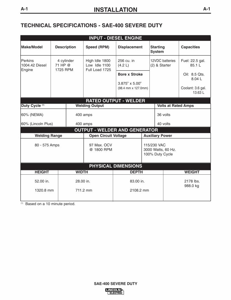
TECHNICAL SPECIFICATIONS - SAE-400 SEVERE DUTY
Make/Model Description Speed (RPM) Displacement Starting CapacitiesSystem
Perkins 4 cylinder High Idle 1800 256 cu. in 12VDC batteries Fuel: 22.5 gal.1004.42 Diesel 71 HP @ Low Idle 1100 (4.2 L) (2) & Starter 85.1 LEngine 1725 RPM Full Load 1725
Bore x Stroke Oil: 8.5 Qts.8.04 L
3.875” x 5.00”(98.4 mm x 127.0mm) Coolant: 3.6 gal.
13.63 L
INPUT - DIESEL ENGINE
RATED OUTPUT - WELDER
HEIGHT WIDTH DEPTH WEIGHT
52.00 in. 28.00 in. 83.00 in. 2178 lbs.988.0 kg
1320.8 mm 711.2 mm 2108.2 mm
OUTPUT - WELDER AND GENERATOR
Duty Cycle (1) Welding Output Volts at Rated Amps
60% (NEMA) 400 amps 36 volts
60% (Lincoln Plus) 400 amps 40 volts
Welding Range Open Circuit Voltage Auxiliary Power
80 - 575 Amps 97 Max. OCV 115/230 VAC@ 1800 RPM 3000 Watts, 60 Hz.
100% Duty Cycle
PHYSICAL DIMENSIONS
(1) Based on a 10 minute period.
A-2INSTALLATION
SAE-400 SEVERE DUTY
A-2
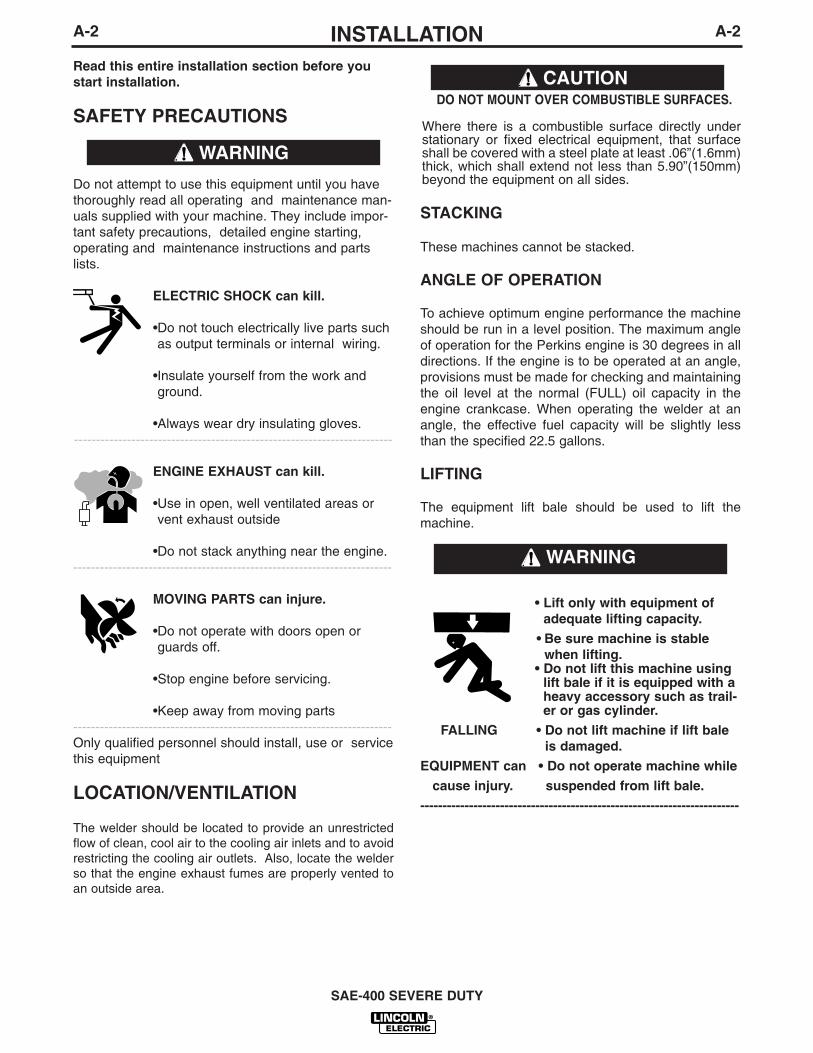
Read this entire installation section before youstart installation.
SAFETY PRECAUTIONS
Do not attempt to use this equipment until you havethoroughly read all operating and maintenance man-uals supplied with your machine. They include impor-tant safety precautions, detailed engine starting,operating and maintenance instructions and partslists.
ELECTRIC SHOCK can kill.
•Do not touch electrically live parts suchas output terminals or internal wiring.
•Insulate yourself from the work andground.
•Always wear dry insulating gloves.------------------------------------------------------------------------
ENGINE EXHAUST can kill.
•Use in open, well ventilated areas orvent exhaust outside
•Do not stack anything near the engine.------------------------------------------------------------------------
MOVING PARTS can injure.
•Do not operate with doors open orguards off.
•Stop engine before servicing.
•Keep away from moving parts------------------------------------------------------------------------Only qualified personnel should install, use or servicethis equipment
LOCATION/VENTILATION
The welder should be located to provide an unrestrictedflow of clean, cool air to the cooling air inlets and to avoidrestricting the cooling air outlets. Also, locate the welderso that the engine exhaust fumes are properly vented toan outside area.
DO NOT MOUNT OVER COMBUSTIBLE SURFACES.
Where there is a combustible surface directly understationary or fixed electrical equipment, that surfaceshall be covered with a steel plate at least .06”(1.6mm)thick, which shall extend not less than 5.90”(150mm)beyond the equipment on all sides.
STACKING
These machines cannot be stacked.
ANGLE OF OPERATION
To achieve optimum engine performance the machineshould be run in a level position. The maximum angleof operation for the Perkins engine is 30 degrees in alldirections. If the engine is to be operated at an angle,provisions must be made for checking and maintainingthe oil level at the normal (FULL) oil capacity in theengine crankcase. When operating the welder at anangle, the effective fuel capacity will be slightly lessthan the specified 22.5 gallons.
LIFTING
The equipment lift bale should be used to lift themachine.
WARNING
CAUTION
• Lift only with equipment ofadequate lifting capacity.
• Be sure machine is stablewhen lifting.
• Do not lift this machine usinglift bale if it is equipped with aheavy accessory such as trail-er or gas cylinder.
FALLING • Do not lift machine if lift baleis damaged.
EQUIPMENT can • Do not operate machine while
cause injury. suspended from lift bale.
------------------------------------------------------------------------
WARNING
A-3INSTALLATION
SAE-400 SEVERE DUTY
A-3
HIGH ALTITUDE OPERATION
At higher altitudes, output derating may be necessary.As a rule of thumb, derate the welder output 5% forevery 500 meters (1640 ft.) above 1000 meters (3280ft.).
Contact a Perkins Service Representative for anyengine adjustments that may be required for high alti-tude operation.
TOWING
The recommended trailers for use with this equipmentfor in-plant and yard towing by a vehicle
(1)are Lincoln’s
K767-1, K956-1 and K956-2. The K956-1 and K956-2are also designed to be used at highway speeds(1).Ifthe user adapts a non-Lincoln trailer, he must assumeresponsibility that the method of attachment and usagedoes not result in a safety hazard nor damage thewelding equipment. Some of the factors to be consid-ered are as follows:
1. Design capacity of trailer vs. weight of Lincolnequipment and likely additional attachments.
2. Proper support of, and attachment to, the base ofthe welding equipment so that there will be noundue stress to the trailer’s framework.
3. Proper placement of the equipment on the trailer toinsure stability side to side and front to back whenbeing moved and when standing by itself.
4. Typical conditions of use, such as travel speed,roughness of surface on which the trailer will beoperated, and environmental conditions.
5. Proper preventative maintenance of trailer.
6. Conformance with federal, state and local laws.1
(1)For highway use, consult applicable federal, stateand local laws regarding specific requirements foruse on public highways, such as brakes, lights, fend-ers, etc.
VEHICLE MOUNTING
Improperly mounted concentrated loads may causeunstable vehicle handling and tires or other compo-nents to fail.
• Only transport this equipment on serviceable vehi-cles which are rated and designed for such loads.
• Distribute, balance and secure loads so vehicle isstable under conditions of use.
• Do not exceed maximum rated loads for compo-nents such as suspension, axles and tires.
• Mount equipment base to metal bed or frame ofvehicle.
• Follow vehicle manufacturer’s instruction.----------------------------------------------------------------------------
PRE-OPERATION ENGINE SERVICE
READ the engine operating and maintenance instruc-tions supplied with this machine.
ENGINE OIL
The engine is shipped with the engine crankcase filledwith high quality SAE 10W-30 oil (API class CD or bet-ter). Check the oil level before starting the engine. If it isnot up to the full mark on the dip stick, add oil as required.Check the oil level every four hours of running time duringthe first 35 running hours. Refer to the engine Operator’sManual for specific oil recommendations and break-ininformation. The oil change interval is dependent on thequality of the oil and the operating environment. Refer tothe engine Operator’s Manual for the proper service andmaintenance intervals.
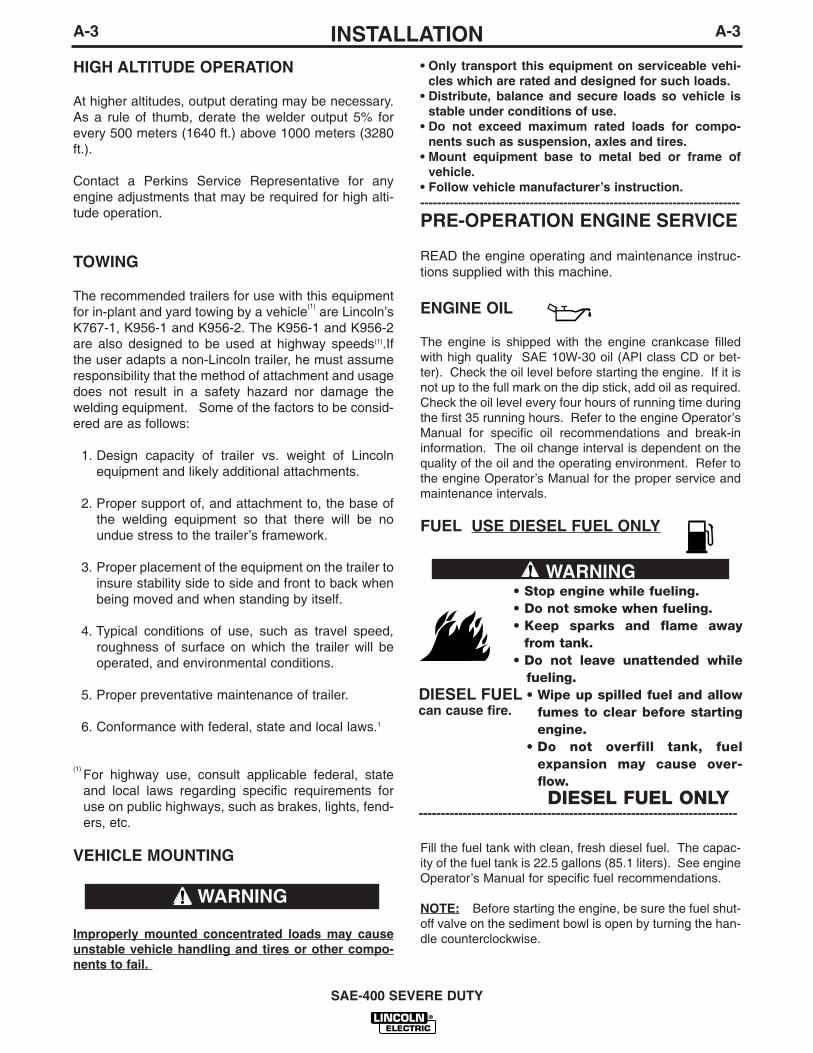
FUEL USE DIESEL FUEL ONLY
Fill the fuel tank with clean, fresh diesel fuel. The capac-ity of the fuel tank is 22.5 gallons (85.1 liters). See engineOperator’s Manual for specific fuel recommendations.
NOTE: Before starting the engine, be sure the fuel shut-off valve on the sediment bowl is open by turning the han-dle counterclockwise.
WARNING
• Stop engine while fueling.• Do not smoke when fueling.• Keep sparks and flame away
from tank.• Do not leave unattended while
fueling.• Wipe up spilled fuel and allow
fumes to clear before startingengine.
• Do not overfill tank, fuelexpansion may cause over-flow.DIESEL FUEL ONLY
------------------------------------------------------------------------
WARNING
DIESEL FUELcan cause fire.

A-4INSTALLATIONA-4
SAE-400 SEVERE DUTY
BATTERY CONNECTION
WARNING: Use caution as the electrolyte is a strongacid that can burn skin and damage eyes.
Remove and discard the insulating caps from the neg-ative battery terminals. Attach and tighten negativebattery cable terminals.
NOTE: This machine is furnished with wet chargedbatteries; if unused for several months, the batteriesmay require a booster charge. Be careful to charge thebatteries with the correct polarity. Make sure that thebatteries are level while charging.
GASES FROM BATTERY can explode.
● Keep sparks, flame and cigarettesaway from battery.
To prevent EXPLOSION when:
● INSTALLING A NEW BATTERY — disconnectnegative cable from old battery first andconnect to new battery last.
● CONNECTING A BATTERY CHARGER —remove battery from welder by disconnectingnegative cable first, then positive cable andbattery clamp. When reinstalling, connectnegative cable last. Keep well ventilated.
● USING A BOOSTER — connect positive lead tobattery first then connect negative lead to neg-ative battery lead at the lower control panelsupport.
BATTERY ACID can burn eyes andskin.
● Wear gloves and eye protectionand be careful when working nearbattery.
● Follow instructions printed on battery.
IMPORTANT: To prevent ELECTRICAL DAMAGEWHEN:
a) Installing new batteries.
b) Using a booster.
Use correct polarity — Negative Ground.To prevent BATTERY BUCKLING, tighten nuts on bat-teries only until snug. DO NOT OVERTIGHTEN.
WARNING
ENGINE BREAK-IN
Lincoln Electric selects high quality, heavy-duty indus-trial engines for the portable welding machines weoffer. While it is normal to see a small amount ofcrankcase oil consumption during initial operation,excessive oil use, wetstacking (oil or tar like substanceat the exhaust port), or excessive smoke is not normal.
Larger machines with a capacity of 350 amperes andhigher, which are operated at low or no-load conditionsfor extended periods of time are especially susceptibleto the conditions described above. To accomplish suc-cessful engine break-in, most diesel-powered equip-ment needs only to be run at a reasonably heavy loadwithin the rating of the welder for some period of timeduring the engine’s early life. However, if the welder issubjected to extensive light loading, occasional moder-ate to heavy loading of the engine may sometimes benecessary. Caution must be observed in correctlyloading a diesel/generator unit.
1. Connect the welder output studs to a suit-able resistive load bank. Note that anyattempt to short the output studs by con-necting the welding leads together, directshorting of the output studs, or connectingthe output leads to a length of steel willresult in catastrophic damage to the gener-ator and voids the warranty.
2. Set the welder controls for an output cur-rent and voltage within the welder ratingand duty cycle. Note that any attempt toexceed the welder rating or duty cycle forany period of time will result in catastrophicdamage to the generator and voids thewarranty.
3. Periodically shut off the engine and checkthe crankcase oil level.
ENGINE COOLING SYSTEM
The cooling system has been filled at the factory witha 50-50 mixture of ethylene glycol antifreeze andwater. Check the radiator level and add a 50-50 solu-tion as needed. (See Engine Manual or antifreezecontainer for alternate antifreeze recommendation.)

A-5INSTALLATION
SAE-400 SEVERE DUTY
A-5
WELDING OUTPUT CABLES
With the engine off, connect the electrode and workcables to the studs provided. These connectionsshould be checked periodically and tightened if neces-sary.
Listed in Table A.1 are copper cable sizes recom-mended for the rated current and duty cycle. Lengthsstipulated are the distance from the welder to work andback to the welder again. Cable sizes are increasedfor greater lengths primarily for the purpose of mini-mizing cable voltage drop.
Table A.1 Combined Length of Electrode andWork Cables.
MACHINE GROUNDING
Because this portable engine driven welder creates itsown power, it is not necessary to connect its frame toan earth ground, unless the machine is connected topremises wiring (home, shop, etc.).
To prevent dangerous electric shock, other equipmentpowered by this engine driven welder must:
a) be grounded to the frame of the welder using agrounded type plug,
orb) be double insulated.
When this welder is mounted on a truck or trailer, itsframe must be securely connected to the metal frameof the vehicle. When this engine driven welder is con-nected to premises wiring such as that in a home orshop, its frame must be connected to the system earthground. See the article on grounding in the latest U.S.National Electrical Code and the local code.
In general, if the machine is to be grounded, it shouldbe connected with a #8 or larger copper wire to a solidearth ground such as a metal water pipe going into theground for at least ten feet and having no insulatedjoints, or to the metal framework of a building whichhas been effectively grounded. The U.S. NationalElectrical Code lists a number of alternate means ofgrounding electrical equipment. A machine groundingstud marked with the symbol is provided on thewelding generator frame foot.
Up to 100 FT.(Up to 30m)
2/0 AWG
100-200 FT.(30m-61m)
3/0 AWG
200-250 FT.(61m-76m)
4/0 AWG
AMPS@60%
Duty Cycle
400
TOTAL COMBINED LENGTH OF ELEC-TRODE AND WORK CABLES
SPARK ARRESTORThe muffler included with this welder has been modi-fied and now qualifies as a spark arrestor. Mufflers on
machines manufactured before this change do notqualify as spark arrestors and were shipped from thefactory with an additional spark arresting unit for thatpurpose. Integral spark arresting mufflers will have aclean out service plug and will have “USDA FS 51001CQUALIFIED SPARK ARRESTOR” stamped on themuffler shell. Any spark arrestor must be serviced andproperly maintained. For machines with separate sparkarrestors, secure the arrestor to the outlet tube on themuffler using the clamp provided.An incorrect spark arrester may lead to damage tothe engine or adversely affect performance.------------------------------------------------------------------------
WARNING
Allow engine to cool before
Do not operate engine while
servicing spark arrestor!
servicing spark arrestor!
• Spark Arrestor and Muffler may be hot!
CAUTION

B-1OPERATIONB-1
WELDING SPARKS can causefire or explosion.
• Do not weld near flammable material .• Do not weld on containers that have
held flammable material.-----------------------------------------------------------
MOVING PARTS can injure.• Keep away from moving parts• Do not operate with doors open or
guards off.• Stop engine before servicing.
------------------------------------------------------------------------ENGINE EXHAUST can kill.• Use in open, well ventilated areas or
vent exhaust outside.
------------------------------------------------------------------------ADDITIONAL SAFETY PRECAUTIONS
Always operate the welder with the hinged doorsclosed as these provide maximum protection frommoving parts and insure proper cooling air flow.
Read carefully the Safety Precautions page in theInstruction Manual before operating this machine.Always follow these and any other safety proceduresincluded in this manual and in the engine and com-pressor instruction manuals.
GENERAL DESCRIPTION
The SAE-400 SEVERE DUTY is a diesel engine drivenwelding power source. The machine uses a DC gener-ator for DC stick electrode welding and an AC exciterfor 115/230 VAC auxiliary power. As a generator it cansupply up to 3,000 watts of 115/230 volt AC power. Asa welder it provides up to 575 amps of DC constantcurrent output.
The engine is a 71 Hp (54kw), 4-cylinder water cooleddiesel made by Perkins.
RECOMMENDED APPLICATIONS
WELDER
The SAE-400 SEVERE DUTY provides excellent con-stant current DC welding output for stick (SMAW) weld-ing.
AUXILIARY POWER
The SAE-400 SEVERE DUTY provides 3 KW of115/230 VAC output for auxiliary power and emer-gency standby power.
OPERATING INSTRUCTIONS
Read and understand this entire section before operat-ing your equipment.
SAFETY INSTRUCTIONS
Do not attempt to use this equipment until you havethoroughly read all operating and maintenance manu-als supplied with your machine. They include importantsafety precautions, detailed engine starting, operatingand maintenance instructions and parts lists.
ELECTRIC SHOCK can kill.• Do not touch electrically live parts or
electrodes with your skin or wet cloth-ing.
• Insulate yourself from the work andground.
• Always wear dry insulating gloves. • Do not use AC welder if your clothing,
gloves or work area is damp or ifworking on, under or inside work-piece.Use the following equipment:
• Semiautomatic DC constant voltage(wire) welder.
• DC manual (stick) welder.• AC welder with reduced voltage con-
trol.------------------------------------------------------------------------
ARC RAYS can injure eyes andburn skin.
• Wear eye, ear, and body protection.
----------------------------------------------------------
• Only qualified personnel should install, use orservice this equipment.
• Consult instruction manual before operating.----------------------------------------------------------------------Before operating, read and understand the manu-facturer’s instructions for this equipment and theconsumables to be used including the MaterialSafety Data Sheet (MSDS) and follow youremployer’s safety practices.------------------------------------------------------------------------
FUMES AND GASES can bedangerous to your health.
• Keep your head out of fumes.• Use enough ventilation or exhaust at
the arc, or both, to keep the fumesand gases from your breathing zoneand general area.
SAE-400 SEVERE DUTY
WARNING
B-2OPERATIONB-2
DESIGN FEATURES AND ADVANTAGES
FOR STICK WELDING• Excellent DC constant current output for stick weld-
ing applications.
• Continuous adjustment of both voltage and currentfor unsurpassed welds on demanding jobs.
• Remote control capability standard.
FOR AUXILIARY POWER
• 3,000 watts of 115/230 VAC, 60 Hz auxiliary power.
• One 20 amp 115 VAC duplex receptacle for up to 26amps of 115 VAC power.
• One 15 amp, 230 VAC duplex receptacle for up to 13amps of 230 VAC power.
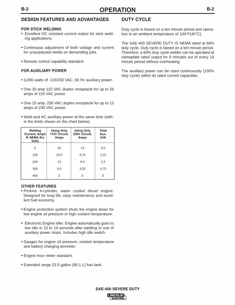
• Weld and AC auxiliary power at the same time (with-in the limits shown on the chart below).
OTHER FEATURES• Perkins 4-cylinder, water cooled diesel engine.
Designed for long life, easy maintenance and excel-lent fuel economy.
• Engine protection system shuts the engine down forlow engine oil pressure or high coolant temperature.
• Electronic Engine Idler. Engine automatically goes tolow idle in 10 to 14 seconds after welding or use ofauxiliary power stops. Includes high idle switch.
• Gauges for engine oil pressure, coolant temperatureand battery charging ammeter.
• Engine hour meter standard.
• Extended range 22.5 gallon (85.1 L) fuel tank.
DUTY CYCLE
Duty cycle is based on a ten minute period and opera-tion in an ambient temperature of 104°F(40°C).
The SAE-400 SEVERE DUTY IS NEMA rated at 60%duty cycle. Duty cycle is based on a ten minute period.Therefore, a 60% duty cycle welder can be operated atnameplate rated output for 6 minutes out of every 10minute period without overheating.
The auxiliary power can be used continuously (100%duty cycle) within its rated current capacities.
SAE-400 SEVERE DUTY
Welding Using Only Using Only TotalCurrent, Amps 115V Circuit, 230V Circuit, Aux.@ NEMA Arc Amps Amps kVA
Volts
0 26 13 3.0
100 19.5 9.75 2.25
200 13 6.5 1.5
300 6.5 3.25 0.75
400 0 0 0
B-3OPERATIONB-3
ENGINE CONTROLS
IGNITION SWITCH
When placed in the “ON” position, this switch ener-gizes the fuel solenoid. When placed in the “OFF” posi-tion, the flow of fuel to the injection pump is stopped toshut down the engine.
“IDLER” SWITCH
The idler switch has two positions, “HIGH” and“AUTO”.
When in “HIGH” ( ) position, the engine will runcontinuously at high idle.
When in “AUTO” ( / ) idle position, the idleroperates as follows:
a. Welding
When the electrode touches the work, the weldingarc is initiated and the engine accelerates to fullspeed.
After welding ceases (and no auxiliary power isbeing drawn), the engine will return to low idle afterapproximately 10 to 14 seconds.
b. Auxiliary Power
With the engine running at low idle and auxiliarypower for lights or tools is drawn (approximately100-150 watts or greater) from the receptacles, theengine will accelerate to high speed. If no power isbeing drawn from the receptacles ( and not weld-ing) for 10-14 seconds, the idler reduces the enginespeed to low idle.
ENGINE TEMPERATURE GAUGE
Displays the coolant temperature in the engine block.
ENGINE OIL PRESSURE GAUGE
Displays the oil pressure to the engine. When theengine starts running, watch for the oil pressure tobuild up. If no pressure shows within 30 seconds, stopthe engine and consult the engine instruction manual.
BATTERY CHARGING AMMETER
Displays the current going from the charging alternatorinto the batteries. It is normal for charging current to behigh (above 15 amps) after starting or when the batter-ies are ‘low’ on charge.
ENGINE HOUR METER
The engine hour meter records the total running timeon the engine in hours. It can be used to keep a recordof maintenance on the engine and or welder.
ENGINE PROTECTION SYSTEM
The engine protection system shuts down the engineunder high coolant temperature or low engine oil pres-sure conditions by allowing the fuel solenoid valve toclose.
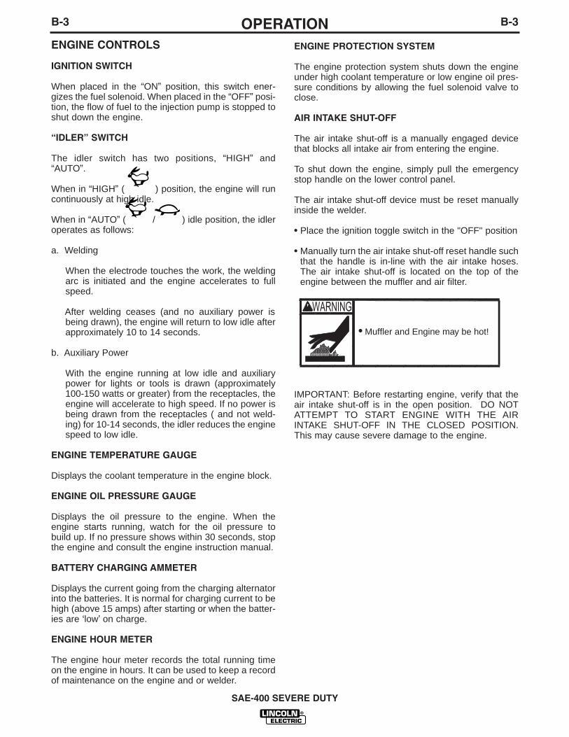
AIR INTAKE SHUT-OFF
The air intake shut-off is a manually engaged devicethat blocks all intake air from entering the engine.
To shut down the engine, simply pull the emergencystop handle on the lower control panel.
The air intake shut-off device must be reset manuallyinside the welder.
• Place the ignition toggle switch in the "OFF" position
• Manually turn the air intake shut-off reset handle suchthat the handle is in-line with the air intake hoses.The air intake shut-off is located on the top of theengine between the muffler and air filter.
IMPORTANT: Before restarting engine, verify that theair intake shut-off is in the open position. DO NOTATTEMPT TO START ENGINE WITH THE AIRINTAKE SHUT-OFF IN THE CLOSED POSITION.This may cause severe damage to the engine.
SAE-400 SEVERE DUTY
WARNING
• Muffler and Engine may be hot!
B-4OPERATIONB-4
WELDER CONTROLSPOLARITY SWITCH
Turn the Arc Polarity switch to electrode positive orelectrode negative as required for each particularapplication.
CONTROL OF WELDING CURRENTPurpose of Controls
The continuous “Current Control” is the main currentadjuster. The “Job Selector” is both a fine currentadjuster and the continuous Open Circuit Voltageadjuster. Open Circuit Voltage (OCV) controls the arccharacteristics.
“Job Selector”
The “Job Selector” dial is divided into four colored sec-tions providing OCV ranges as follows:
Color Title OCV RangeWhite Large Electrodes High OCVBlack Normal Welding Medium OCVRed Overhead & Vertical Low OCVGrey Special Applications Extra-Low OCV
The “Job Selector” is usually set in the black rangebecause it provides a soft “Buttering “ arc desired formost welding. Some operators prefer to set the “JobSelector” in the red range for a snappy “Digging” arcwhen welding vertical up or overhead.
“Current Control”
Do not adjust the “Current Control” while weldingbecause this can damage the control.------------------------------------------------------------------------The “Current Control” dial is calibrated in amperes onthree separate colored dials corresponding to thewhite, black and red ranges of the “Job Selector” dial.For example: when the “Job Selector” is set on theblack range, the approximate welding current is indi-cated on the black scale of the “Current Control” dial.
How to Set the Controls
Assume you want a normal soft arc and about 135amps, using a 5/32” (4.0 mm) electrode:
1. Set the “Job Selector” at the center of the blackrange.
2. Set the “Current Control” to read 135 amps on theblack dial.
3. Start to weld.
4. If you want a little more current, turn the “JobSelector” up (counterclockwise) to increase cur-rent. If you want a little less current, turn the “JobSelector” down (clockwise) to decrease current.
5. If dialing the desired current with the “JobSelector” moves the setting outside the blackrange causing undesirable arc characteristics, turnthe “Job Selector” back to the center of the blackrange. Then turn the “Current Control” up or downa little as needed. Readjust the “Job Selector” forthe exact characteristics and current desired.
REMOTE CONTROL
A receptacle and “Local/Remote” control switch on thelower front control panel and a remote control box with100 ft. (30.5 m) of cord for adjusting the OCV at thewelding site are standard. Putting the switch in the“REMOTE” position allows fine current control at theremote control box while placing the switch in the“LOCAL” position allows fine current control at the “JobSelector” on the machine.
AUXILIARY POWER CONTROLS
Note: GFCI receptacles our an option and if installed,see the “MAINTENANCE SECTION” for detailedinformation on testing and resetting the GFCIreceptacle.
115 VAC Receptacle
One 20 amp, 115 VAC duplex receptacle provides 115VAC for auxiliary power. A total of 26 amps can bedrawn from this receptacle.
230 VAC Receptacle
One 15 amp, 230 VAC duplex receptacle provides 230VAC for auxiliary power. A total of 13 amps can bedrawn from this receptacle.
Circuit Breakers
The circuit breakers provide separate overload currentprotection for each half of the 115 V duplex receptacle.The circuit breakers provide overload current protec-tion in both current carrying wires of the 230 V duplexreceptacle.
Ground Stud
Provides a connection point for connecting themachine to earth ground. For the safest grounding pro-cedure refer to “Machine Grounding” in the INSTALLA-TION section of this manual.
SAE-400 SEVERE DUTY
CAUTION

B-5OPERATIONB-5
ENGINE OPERATION
Do not adjust the high idle engine speed (rpm)above the factory setting specification.------------------------------------------------------------------------STARTING INSTRUCTIONS
Be sure all Pre-Operation Maintenance has been per-formed. (See INSTALLATION section of this manual).To start the engine, place ignition toggle switch in the“ON” position. Engage the starter button. When theengine starts running, observe the engine oil pressure.If no pressure shows within 30 seconds, stop theengine and consult the engine operating manual. Tostop the engine, place the ignition toggle switch in the“OFF” position.
When an engine is started for the first time, some ofthe oil will be needed to fill the passages of the lubri-cating system. Therefore, on initial starting, run theengine for about five minutes and then stop the engineand recheck the oil. If the level is down, fill to the fullmark again. The engine controls were properly set atthe factory and should require no adjusting whenreceived.
For added safety always operate the welder with thedoors closed. Further, leaving the doors open changesthe designed air flow and may cause engine or gener-ator overheating.
Cold Weather Starting
Never use any other starting aids, such as ether,when using the “Thermostart” system.------------------------------------------------------------------------When overnight temperatures are between 10°F(12°C)and freezing, use the standard “Thermostart” startingsystem installed on all engines. Follow the instructionson the start panel nameplate and in the engine manu-al shipped with the welder. With fully charged batter-ies and the proper weight oil, the “Thermostart” systemoperates satisfactorily even down to about 0°F (-18°C).
BREAK-IN PERIOD
ENGINE
The engine used to supply power for your welder is aheavy duty, industrial engine. It is designed and builtfor rugged use. It is very normal for any engine to usesmall quantities of oil until the break-in is accom-plished. Check the oil level twice a day during thebreak-in period (about 100 running hours).
IMPORTANT: IN ORDER TO ACCOMPLISH THISBREAK-IN, THE UNIT SHOULD BE SUBJECTED TOHEAVY LOADS, WITHIN THE RATING OF THEMACHINE. AVOID LONG IDLE RUNNING PERIODS.
TYPICAL FUEL CONSUMPTION
The typical fuel consumption of the SAE-400 SEVEREDUTY for various operating scenarios is shown below:
Low Idle - No Load .35 gal./ hr.1100 RPM (1.32 L./hr.)
High Idle - No Load .75 gal./hr.1800 RPM (2.84 L./hr.)
Welding Load 1.92 gal./hr.400 Amps, 40 Volts (7.27 L./hr.)
Auxiliary Power .96 gal./hr.3000VA (3.63 L./hr.)
SAE-400 SEVERE DUTY
WARNING
CAUTION
C-1ACCESSORIESC-1
OPTIONAL FIELD INSTALLEDACCESSORIES
K802-D Power Plug Kit - Kit includes male plugs foreach auxiliary receptacle.
K767-1 Trailer - A 4-wheel steerable trailer for in-plantand yard towing(1) with E78-14 load range (B) tubelesstires. Mounts directly to welder base.
K956-1 and -2 Trailer - A 2-wheel trailer designed forroad(1), off road, in-plant and yard towing. The K956-2trailer is equipped with electric brakes. Trailer mountsdirectly to welder base.1For highway use, consult applicable federal, state and local laws regardingpossible requirements for brakes, lights, fenders, etc.
K704 Standard Accessory Kit - Includes electrodeand work cables, headshield, work clamp and elec-trode holder.
K1690-1 GFCI RECEPTACLE KITIncludes one UL approved 120V ground fault circuitinterrupter duplex type receptacle with cover andinstallation instructions. Replaces the factory installed
120V duplex receptacle. Each receptacle of the GFCIDuplex is rated at 20 Amps, the maximum total current
from the GFCI Duplex is limited to the 20 Amps. Twokits are required. See the MAINTENANCE section fordetailed information on testing and resetting the GFCIreceptacle.
SAE-400 SEVERE DUTY
D-1MAINTENANCED-1
ELECTRIC SHOCK can kill.
● Do not touch electrically live partssuch as output terminals or inter-nal wiring
ENGINE EXHAUST can kill.
● Use in open, well ventilated areasor vent exhaust outside
MOVING PARTS can injure.
● Do not operate with doors open orguards off
● Stop engine before servicing
● Keep away from moving parts
● Remove guards only when necessary andreplace when work requiring removal is com-plete.
● Only qualified personnel should install, use, orservice this equipment.
ROUTINE MAINTENANCE
At the end of each day’s welding, refill the fuel tank tominimize moisture condensation in the tank. Also, run-ning out of fuel tends to draw dirt into the fuel system.Check the engine crankcase oil level.
If the fuel supply runs out while the fuel pump is oper-ating, air may be entrapped in the fuel distribution sys-tem. If this happens, bleeding of the fuel system maybe necessary. See the engine instruction manual.
PERIODIC MAINTENANCE
1. Blow out the welder and controls with an air hose at leastonce every two months. In particularly dirty locations, thiscleaning may be necessary once a week. Use low pres-sure air to avoid driving dirt into the insulation.
2. The current control reactor brushes are self-lubricatingand should not be greased. Keep the contacts clean. Thiscontrol should be moved from maximum to minimum dailyto prevent the controls from sticking.
3. See the engine Instruction Manual for periodic enginemaintenance information. Change the oil filter in accor-dance with the instructions in the engine operating man-ual. When the oil filter is changed add one quart of oil tothe crankcase to replace the oil held in the filter duringoperation.
4. Belts tend to loosen after the first 30 or 40 hours of oper-ation. Check the cooling fan belt and tighten if necessary.DO NOT OVER TIGHTEN.
ENGINE OIL CHANGE
The SAE-400 SEVERE DUTY is equipped with a convenientoil drain system. Drain the oil when the engine is warm toassure rapid and complete draining.
• Remove the oil filler cap and dipstick.
• To open drain valve, push handle away from valve and turn90°.
• Drain oil into a suitable container.
• To close drain valve, turn handle 90° till handle snaps in theclosed position.
• Refill engine with the recommended oil to the appropriatelevel. Replace dipstick and tighten the oil filler cap secure-ly.
Change the crankcase oil at regular intervals using the prop-er grade of oil as recommended in the Engine OperatingManual. Wash your hands with soap and water after handlingused oil. Please dispose of used motor oil in a manner that iscompatible with the environment. We suggest you take it in asealed container to your local service station or recyclingcenter for reclamation. Do not throw it in the trash, pour it onthe ground or down a drain.
ENGINE AIR FILTER
The engine air filter element is a dry cartridge type. Itis located above the engine. It can be cleaned and re-used; however, damaged elements should not bewashed or re-used. Remove loose dirt from elementwith compressed air or water hose directed from insideout. Compressed Air: 100 psi maximum. The filtershould never be removed while the engine is running.
SAE-400 SEVERE DUTY
WARNING
D-2MAINTENANCED-2
BEARING MAINTENANCE
This welder is equipped with a double-shielded ball bearinghaving sufficient grease to last indefinitely under normal ser-vice. Where the welder is used constantly or in excessivelydirty locations, it may be necessary to add one-half ounce ofgrease per year. A pad of grease one inch wide, one inchlong and one inch high weighs approximately one-halfounce. Over greasing is far worse than insufficient greasing.
When greasing the bearings, keep all dirt out of the area.Wipe the fittings completely clean and use clean equipment.More bearing failures are caused by dirt introduced duringgreasing than from insufficient grease.
COMMUTATOR AND BRUSH MAINTENANCE
Uncovered rotating equipment can be dangerous.Use care so your hands, hair, clothing or tools donot catch in the rotating parts. Protect yourselffrom particles that may be thrown out by the rotat-ing armature when stoning the commutator.------------------------------------------------------------------------The generator brushes are properly adjusted when thewelder is shipped. They require no particular attention.DO NOT SHIFT THE BRUSHES or adjust the rockersetting.
Shifting of the brushes may result in:- Change in machine output- Commutator Damage- Excessive brush wear
Periodically inspect the commutator, slip rings andbrushes by removing the covers. DO NOT remove orreplace these covers while the machine is running.Commutators and slip rings require little attention.However, if they are black or appear uneven, havethem cleaned by an experienced maintenance manusing fine sandpaper or a commutator stone. Neveruse emery cloth or paper for this purpose.
NOTE: If the welder is used in dirty or dusty locations,or if the welder is not used for prolonged periods oftime, it may be necessary to clean the commutator andslip rings more often.
Replace brushes when they wear within 1/4" of the pig-tail. A complete set of replacement brushes should bekept on hand. Lincoln brushes have a curved face to fitthe commutator. Have an experienced maintenanceman seat these brushes by lightly stoning the commu-tator as the armature rotates at full speed until contactis made across the full face of the brushes. After ston-ing, blow out the dust with low pressure air.
To seat the slip ring brushes, position the brushes inplace. Then slide one end of a piece of fine sandpaperbetween slip rings and brushes with the coarse sideagainst the brushes. Pull the sandpaper around the cir-cumference of the rings, in direction of rotation only -until brushes seat properly. In addition, stone slip ringwith a fine stone. Brushes must be seated 100%.
Arcing or excessive exciter brush wear indicates a pos-sible misaligned shaft. Have an authorized FieldService Shop check and realign the shaft.
COOLING SYSTEM
The SAE-400 SEVERE DUTY is equipped with a pres-sure radiator. Keep the radiator cap tight to preventloss of coolant. Clean and flush the cooling systemperiodically to prevent clogging the passage and over-heating the engine. When antifreeze is needed, alwaysuse the permanent type.
FUEL FILTERS
When working on the fuel system
• Keep ungrounded lights away, do notsmoke !
• Do not spill fuel !
------------------------------------------------------------------------The SAE-400 SEVERE DUTY is equipped with a FuelPre-Filter/Water Separator Assembly located beforethe lift pump and a Secondary Fuel Filter located afterthe lift pump and before the fuel injectors. The FuelPre-Filter/Water Separator is mounted to the engineblock just below the lift pump. The Secondary Fuel Filter is mounted directly to theengine just above the oil filter.
FUEL PRE-FILTER/WATER SEPARATOR ASSEMBLY
The pre-filter is a 150 micron screen designed to pro-tect against gross fuel contamination of the water sep-arator element and the Secondary Fuel Filter. If thepre-filter becomes plugged it may be removed, inspect-ed, cleaned and reinstalled. In general this only needsto be done with each water separator element change(about every 1,000 hrs.) However if at any time exces-sive fuel contamination is suspected or a sudden fall-off in engine performance is detected the pre-filterscreen should be inspected and cleaned. Follow thefollowing procedure:
SAE-400 SEVERE DUTY
WARNING
WARNING
D-3MAINTENANCED-3
1. Close the fuel shutoff valve located on the fuelstrainer mounted to the under side of the fuel tank.
2. Unscrew the cap ring located on the top of the filterheader and remove the plastic center cap and O-ring.
3. Remove the large white volume plug located direct-ly under the center cap in the upper cavity of the fil-ter header. Use a small screwdriver (or similardevice) to lift the plug part way out of the cavity toassist with its removal.
Be careful not to damage the pre-filter screen withthe tool used to remove the plug.
4. Using a pair of pliers, gently tug on the pull tabs ofthe pre-filter screen in an alternating pattern togradually remove the pre-filter screen.
5. Brush off any debris and rinse in diesel fuel.
6. Re-install the pre-filter screen into the upper cavityof the filter header making sure the four pull tabsare pointing up. Putting your fingers on the pulltabs, push down evenly until the lower body of thepre-filter screen contacts the floor of the upper cav-ity.
7. Re-insert the large white volume plug into the uppercavity.
8. Place the O-ring onto the angled seal surface of thefilter header and re-install the plastic cap. Makesure its flange rests on the O-ring.
9. Screw on the cap ring and tighten hand tight.
10. Remember to open the fuel shutoff valve beforestarting the engine.
WATER SEPARATOR ELEMENT
The water separator element is a two stage filter with aspecial filtration/water separating media, and anexpanded water reservoir providing maximum protec-tion against water in the fuel. The recommendedchange interval for the water separator element is1,000 hours. The procedure for changing the elementis as follows:
1. Close the fuel shutoff valve located on the fuelstrainer mounted to the under side of the fuel tank.
2. Rotate the quick change ring (located just below fil-ter header) clockwise approximately 1/2 turn andslide it down and off of the element.
3. Grasp the element and pull down with a slight rock-ing motion to remove the element from the grom-met post on the bottom of the filter header.
4. Slide the new element onto the grommet post on thebottom of the filter header until the element no longereasily moves up into the filter header. Now rotate theelement (may take almost 1 full turn) with a slightupward pressure until the element begins to furtherengage the header. With the proper orientation nowestablished apply additional pressure to seat the ele-ment in the filter header. You should feel the element“pop” into place when properly seated.
Note: The element will only go on one way. Never useexcessive force when mounting the element to theheader.
5. Slide the quick change ring up over the element androtate counter clockwise until an audible click or popis heard. If you do not hear the click you have not rotat-ed the ring far enough and the element is not in thelocked position. Another indication that the ring is inthe locked position is that one set (it doesn’t matterwhich one) of arrows located on the outside of the ringshould be located directly under the air vent valve.
6. Open the fuel shutoff valve.
7. Open the air vent valve on the front of the filter head-er until fuel emerges free of air bubbles and then closethe air vent valve.
Note : Consult your engine operation manual for infor-mation on air bleeding the entire fuel system.
SECONDARY FUEL FILTER
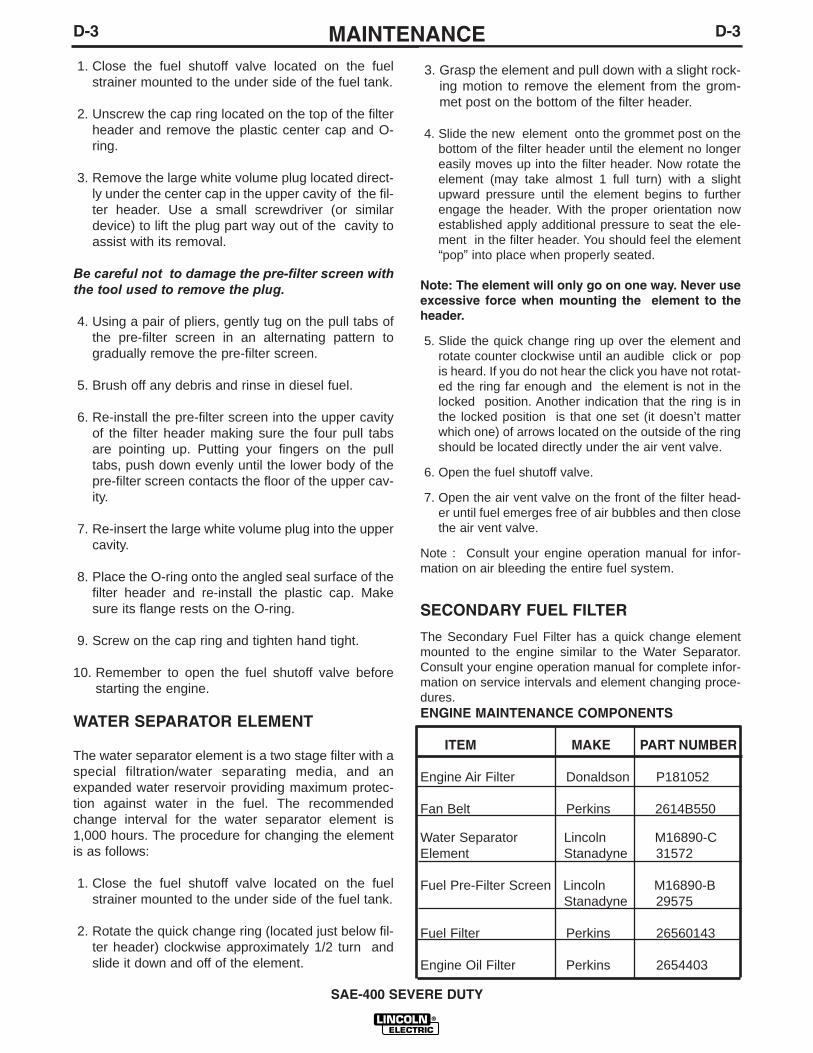
The Secondary Fuel Filter has a quick change elementmounted to the engine similar to the Water Separator.Consult your engine operation manual for complete infor-mation on service intervals and element changing proce-dures.ENGINE MAINTENANCE COMPONENTS
ITEM MAKE PART NUMBER
Engine Air Filter Donaldson P181052
Fan Belt Perkins 2614B550
Water Separator Lincoln M16890-CElement Stanadyne 31572
Fuel Pre-Filter Screen Lincoln M16890-BStanadyne 29575
Fuel Filter Perkins 26560143
Engine Oil Filter Perkins 2654403
SAE-400 SEVERE DUTY
D-4MAINTENANCED-4
SPARK ARRESTOR
For machines with separate spark arresting unit:
Service the spark arrestor every 100 hours of opera-tion or twice a year, which ever occurs first. Service as follows:
1. Stop engine and allow to cool.
2. Loosen clamp and remove spark arrestor frommachine.
3. Remove locknut on top of spark arrestor housingand lift off cap.
4. Separate plates and clean if necessary.
5. Inspect plates and housing for holes or cracks.Replace spark arrestor if damaged.
6. Assemble spark arrestor using reverse order: step3, then step 2.
For machines with integral spark arresting muf-flers:
Service spark arrestor every 250 hours.Service as follows:
1. Stop engine and allow to cool.
2. Remove clean out plug from the side of the sparkarrestor.
3. Without damaging the spark arrestor, gently tap onthe shell near the clean out plug.
4. Once particles are removed, replace the clean outplug.
GFCI RECEPTACLE TESTING AND RESET-TING PROCEDURE
The GFCI receptacle should be properly tested at leastonce every month or whenever it is tripped. To proper-ly test and reset the GFCI receptacle:
• If the receptacle has tripped, first carefully removeany load and check it for damage.
• If the equipment has been shut down, it must berestarted.
• The equipment needs to be operating at high idlespeed and any necessary adjustments made on thecontrol panel so that the equipment is providing atleast 80 volts to the receptacle input terminals.
• The circuit breaker for this receptacle must not betripped. Reset if necessary.
• Push the "Reset" button located on the GFCI recep-tacle. This will assure normal GFCI operation.
• Plug a night-light (with an "ON/OFF" switch) or otherproduct (such as a lamp) into the GFCI receptacleand turn the product "ON".
• Push the "Test" button located on the GFCI recepta-cle. The night-light or other product should go "OFF".
• Push the "Reset" button, again. The light or otherproduct should go "ON" again.
If the light or other product remains "ON" when the"Test" button is pushed, the GFCI is not working prop-erly or has been incorrectly installed (miswired). If yourGFCI is not working properly, contact a qualified, certi-fied electrician who can assess the situation, rewire theGFCI if necessary or replace the device.
SAE-400 SEVERE DUTY
WARNING
Allow engine to cool before
Do not operate engine while
servicing spark arrestor!
servicing spark arrestor!
• Spark Arrestor and Muffler may be hot!
E-1TROUBLESHOOTINGE-1
SAE-400 SEVERE DUTY
If for any reason you do not understand the test procedures or are unable to perform the tests/repairs safely, contact your LocalLincoln Authorized Field Service Facility for technical troubleshooting assistance before you proceed.
CAUTION
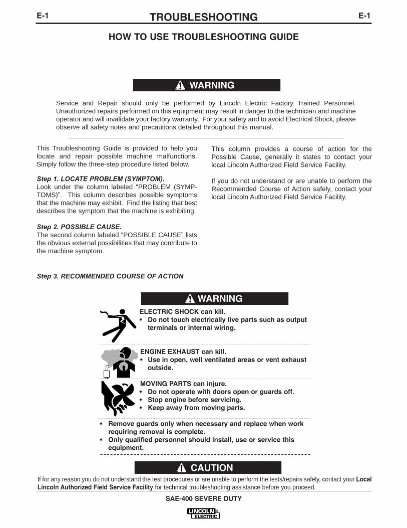
WARNINGELECTRIC SHOCK can kill.• Do not touch electrically live parts such as output
terminals or internal wiring.
ENGINE EXHAUST can kill.• Use in open, well ventilated areas or vent exhaust
outside.
MOVING PARTS can injure.• Do not operate with doors open or guards off.• Stop engine before servicing.• Keep away from moving parts.
• Remove guards only when necessary and replace when workrequiring removal is complete.
• Only qualified personnel should install, use or service thisequipment.
This Troubleshooting Guide is provided to help youlocate and repair possible machine malfunctions.Simply follow the three-step procedure listed below.
Step 1. LOCATE PROBLEM (SYMPTOM).Look under the column labeled “PROBLEM (SYMP-TOMS)”. This column describes possible symptomsthat the machine may exhibit. Find the listing that bestdescribes the symptom that the machine is exhibiting.
Step 2. POSSIBLE CAUSE.The second column labeled “POSSIBLE CAUSE” liststhe obvious external possibilities that may contribute tothe machine symptom.
Step 3. RECOMMENDED COURSE OF ACTION
This column provides a course of action for thePossible Cause, generally it states to contact yourlocal Lincoln Authorized Field Service Facility.
If you do not understand or are unable to perform theRecommended Course of Action safely, contact yourlocal Lincoln Authorized Field Service Facility.
HOW TO USE TROUBLESHOOTING GUIDE
Service and Repair should only be performed by Lincoln Electric Factory Trained Personnel.Unauthorized repairs performed on this equipment may result in danger to the technician and machineoperator and will invalidate your factory warranty. For your safety and to avoid Electrical Shock, pleaseobserve all safety notes and precautions detailed throughout this manual.
__________________________________________________________________________
WARNING
E-2TROUBLESHOOTINGE-2
SAE-400 SEVERE DUTY
Observe all Safety Guidelines detailed throughout this manual
If for any reason you do not understand the test procedures or are unable to perform the tests/repairs safely, contact your LocalLincoln Authorized Field Service Facility for technical troubleshooting assistance before you proceed.
CAUTION
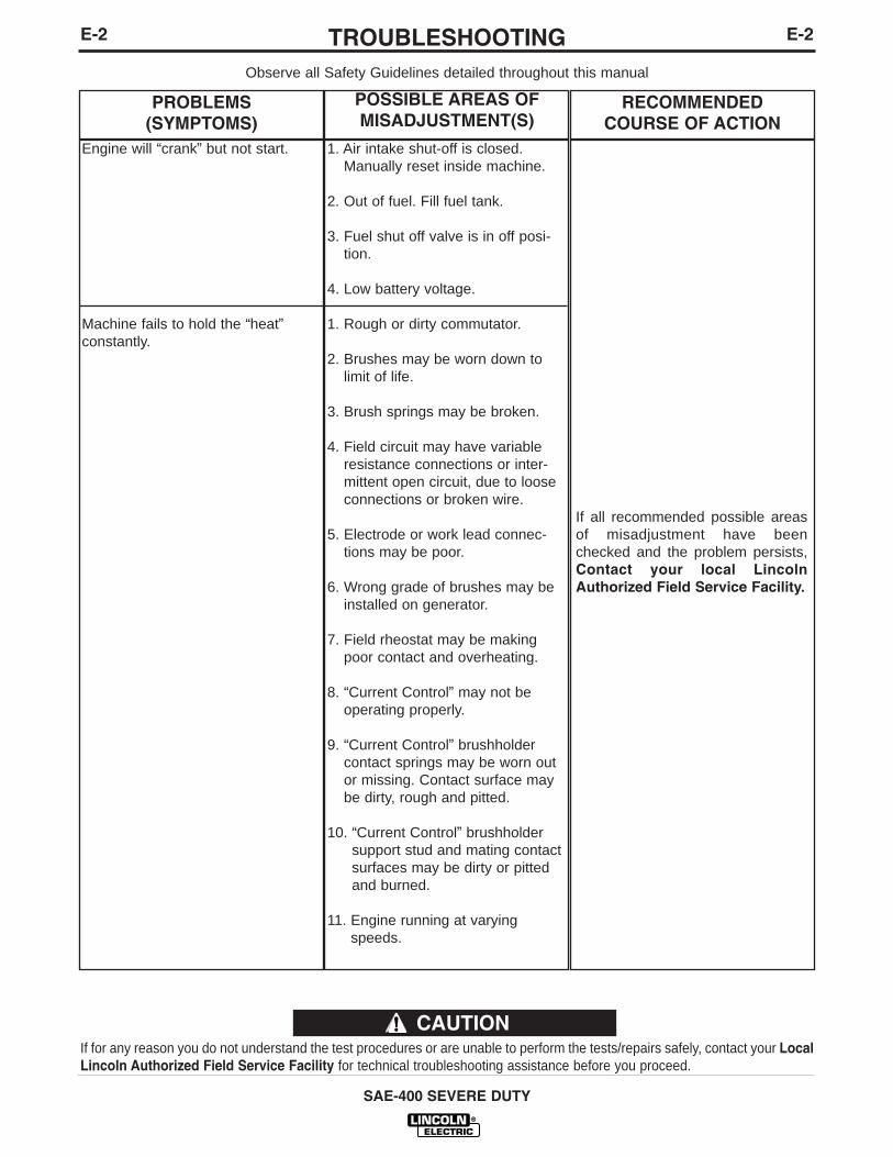
PROBLEMS(SYMPTOMS)
POSSIBLE AREAS OFMISADJUSTMENT(S)
RECOMMENDEDCOURSE OF ACTION
Engine will “crank” but not start.
Machine fails to hold the “heat”constantly.
1. Air intake shut-off is closed.Manually reset inside machine.
2. Out of fuel. Fill fuel tank.
3. Fuel shut off valve is in off posi-tion.
4. Low battery voltage.
1. Rough or dirty commutator.
2. Brushes may be worn down tolimit of life.
3. Brush springs may be broken.
4. Field circuit may have variableresistance connections or inter-mittent open circuit, due to looseconnections or broken wire.
5. Electrode or work lead connec-tions may be poor.
6. Wrong grade of brushes may beinstalled on generator.
7. Field rheostat may be makingpoor contact and overheating.
8. “Current Control” may not beoperating properly.
9. “Current Control” brushholdercontact springs may be worn outor missing. Contact surface maybe dirty, rough and pitted.
10. “Current Control” brushholdersupport stud and mating contactsurfaces may be dirty or pittedand burned.
11. Engine running at varyingspeeds.
If all recommended possible areasof misadjustment have beenchecked and the problem persists,Contact your local LincolnAuthorized Field Service Facility.
E-3TROUBLESHOOTINGE-3
SAE-400 SEVERE DUTY
Observe all Safety Guidelines detailed throughout this manual
If for any reason you do not understand the test procedures or are unable to perform the tests/repairs safely, contact your LocalLincoln Authorized Field Service Facility for technical troubleshooting assistance before you proceed.
CAUTION
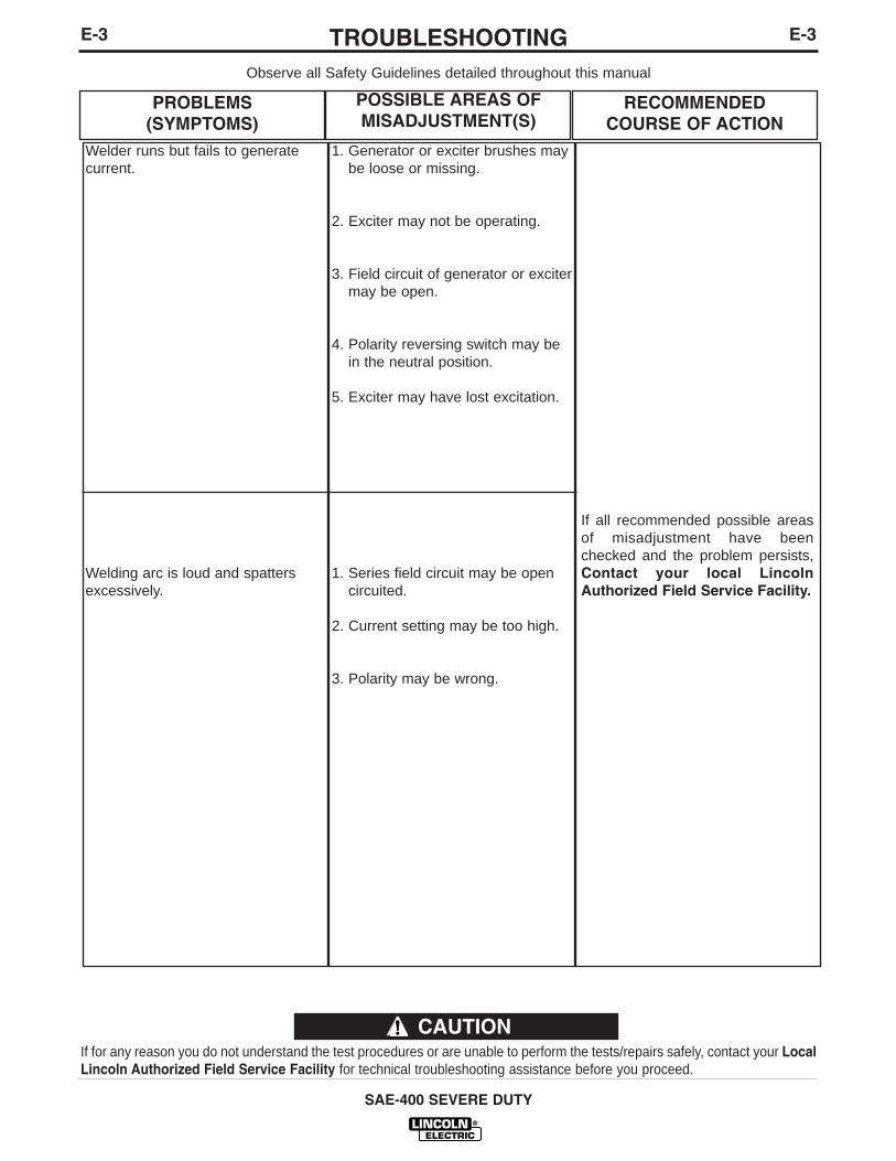
PROBLEMS(SYMPTOMS)
POSSIBLE AREAS OFMISADJUSTMENT(S)
RECOMMENDEDCOURSE OF ACTION
Welder runs but fails to generatecurrent.
Welding arc is loud and spattersexcessively.
1. Generator or exciter brushes maybe loose or missing.
2. Exciter may not be operating.
3. Field circuit of generator or excitermay be open.
4. Polarity reversing switch may bein the neutral position.
5. Exciter may have lost excitation.
1. Series field circuit may be opencircuited.
2. Current setting may be too high.
3. Polarity may be wrong.
If all recommended possible areasof misadjustment have beenchecked and the problem persists,Contact your local LincolnAuthorized Field Service Facility.
E-4TROUBLESHOOTINGE-4
SAE-400 SEVERE DUTY
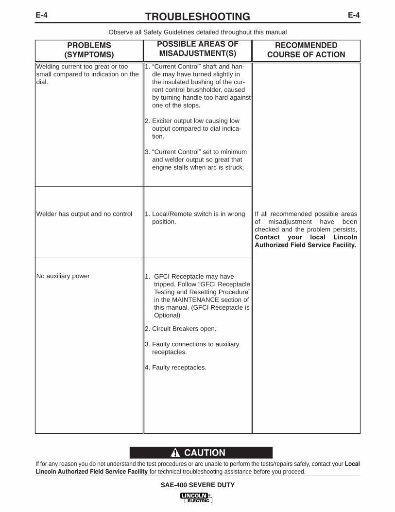
Observe all Safety Guidelines detailed throughout this manual
If for any reason you do not understand the test procedures or are unable to perform the tests/repairs safely, contact your LocalLincoln Authorized Field Service Facility for technical troubleshooting assistance before you proceed.
CAUTION
PROBLEMS(SYMPTOMS)
POSSIBLE AREAS OFMISADJUSTMENT(S)
RECOMMENDEDCOURSE OF ACTION
Welding current too great or toosmall compared to indication on thedial.
Welder has output and no control
No auxiliary power
1. “Current Control” shaft and han-dle may have turned slightly inthe insulated bushing of the cur-rent control brushholder, causedby turning handle too hard againstone of the stops.
2. Exciter output low causing lowoutput compared to dial indica-tion.
3. “Current Control” set to minimumand welder output so great thatengine stalls when arc is struck.
1. Local/Remote switch is in wrongposition.
1. GFCI Receptacle may havetripped. Follow “GFCI ReceptacleTesting and Resetting Procedure”in the MAINTENANCE section ofthis manual. (GFCI Receptacle isOptional)
2. Circuit Breakers open.
3. Faulty connections to auxiliaryreceptacles.
4. Faulty receptacles.
If all recommended possible areasof misadjustment have beenchecked and the problem persists,Contact your local LincolnAuthorized Field Service Facility.
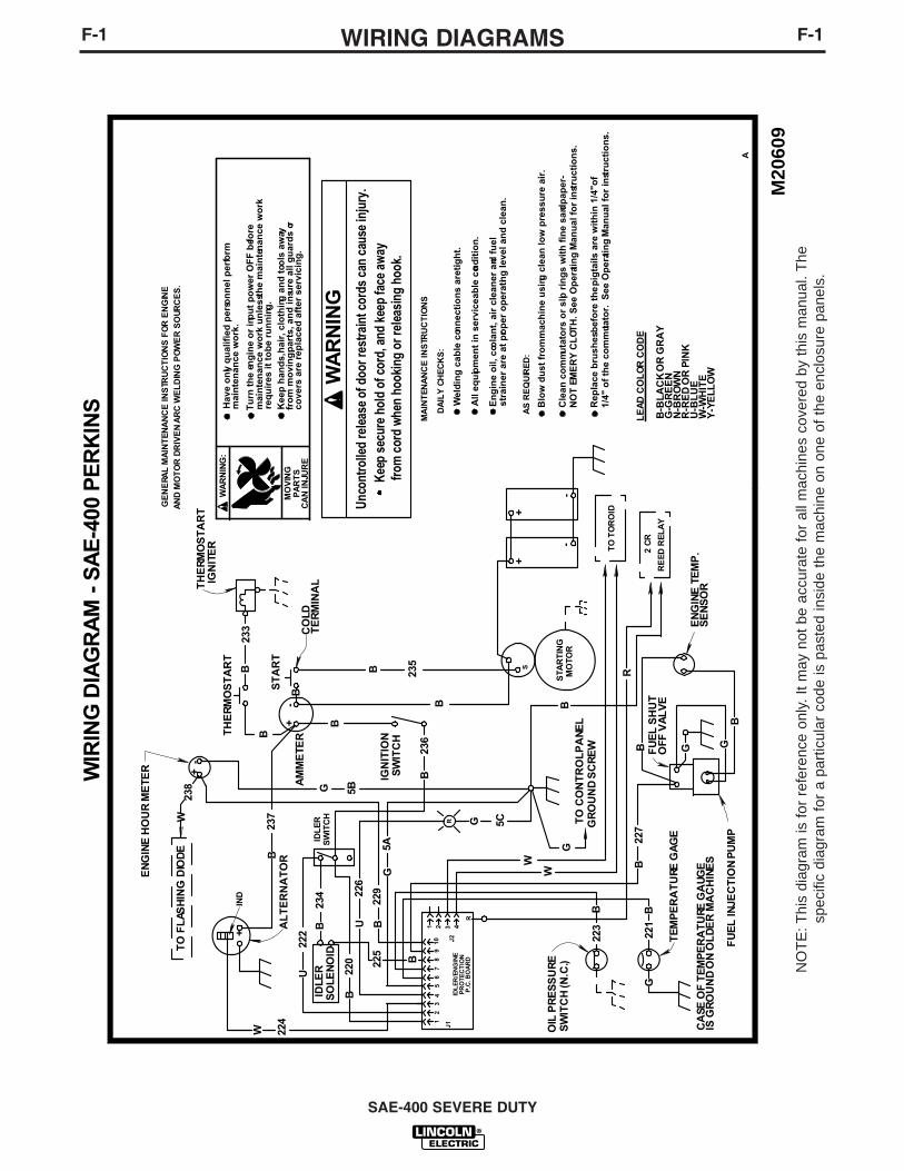
F-1WIRING DIAGRAMS
SAE-400 SEVERE DUTY
F-1
NO
TE
: Thi
s di
agra
m is
for
ref
eren
ce o
nly.
It
may
not
be
accu
rate
for
all
mac
hine
s co
vere
d by
thi
s m
anua
l. T
hesp
ecifi
c di
agra
m f
or a
par
ticul
ar c
ode
is p
aste
d in
side
the
mac
hine
on
one
of t
he e
nclo
sure
pan
els.
SW
ITC
H
PR
OT
EC
TIO
NP
.C. B
OA
RD
IDL
ER
/EN
GIN
EJ1
+
SW
ITC
H (N
.C.)
OIL
PR
ES
SU
RE
TH
ER
MO
ST
AR
T
CO
LDT
ER
MIN
AL
ST
AR
T
B-
TH
ER
MO
ST
AR
T
5C
BB
+
GR
OU
ND
SC
RE
WT
O C
ON
TR
OL
PA
NE
L
B
G
223
W
W
R
432
5A
110
G22
5
B
98
73
2
BSO
LEN
OID
226
234
IDL
ER
RE
ED
RE
LA
Y
S
RB
-
FU
EL
INJE
CT
ION
PU
MP
TE
MP
ER
AT
URE
GA
GE
41
236
SW
ITC
H
BB
IGN
ITIO
N
-
TO
TO
RO
ID
2 C
R
STA
RT
ING
MO
TO
RB
+
FU
EL
SH
UT
GE
NE
RAL
MA
INT
EN
AN
CE
INS
TRU
CT
ION
S F
OR
EN
GIN
E
B B 235
B
AM
ME
TER
G 5B
238
237
B
229
AL
TE
RN
AT
OR
A
M20
609
AN
D M
OT
OR
DR
IVE
N A
RC
WE
LD
ING
PO
WE
R S
OU
RC
ES
.
65
IND
233
B
+
+J2
IGN
ITE
R
W 224
222
U
W
BID
LER
TO
FL
ASH
ING
DIO
DE
EN
GIN
E H
OU
R M
ETE
R
U22
0
B
R
W
IRIN
G D
IAG
RA
M -
SA
E-4
00 P
ER
KIN
S
G
OFF
VA
LV
E
BGG
227
221
EN
GIN
E T
EM
P.
SE
NS
OR
-
PA
RT
SC
AN
INJU
RE
MO
VIN
G
mai
nte
nan
ce w
ork
.
mai
nte
nan
ce w
ork
un
less
the
mai
nte
nan
ce w
ork
Kee
p h
and
s, h
air,
clo
thin
g a
nd
too
ls a
way
req
uir
es it
to
be
run
nin
g.
Tu
rn t
he
eng
ine
or
inp
ut
po
wer
OF
F b
efo
re
Hav
e o
nly
qu
alif
ied
per
son
nel
per
form
WA
RN
ING
:
fro
m m
ovi
ng
par
ts, a
nd
insu
re a
ll g
uar
ds
orco
vers
are
rep
lace
d a
fter
ser
vici
ng
.
AS
RE
QU
IRE
D:
DA
ILY
CH
EC
KS
:
LE
AD
CO
LO
R C
OD
E
MA
INT
EN
AN
CE
INS
TRU
CT
ION
S
B-B
LA
CK
OR
GR
AY
G-G
RE
EN
N-B
RO
WN
R-R
ED
OR
PIN
KU
-BL
UE
W-W
HIT
EY
-YE
LL
OW
En
gin
e o
il, c
oola
nt,
air
cle
aner
and
fu
el
All
equ
ipm
ent
in s
ervi
ceab
le c
ond
itio
n.
Wel
din
g c
able
con
nec
tio
ns
are t
igh
t.
stra
iner
are
at
pro
per
op
erat
ing
leve
l an
d c
lean
.
Blo
w d
ust
fro
m m
ach
ine
usi
ng c
lean
low
pre
ssu
re a
ir.
Cle
an c
om
mu
tato
rs o
r sl
ip r
ing
s w
ith
fin
e sa
ndp
aper
-N
OT
EM
ER
Y C
LO
TH
. See
Op
erat
ing
Man
ual
fo
r in
stru
ctio
ns.
Rep
lace
bru
shes
bef
ore
th
e p
igta
ils a
re w
ith
in 1
/4"o
f1/
4" o
f th
e co
mm
utat
or.
See
Op
erati
ng
Man
ual
fo
r in
stru
ctio
ns.
WA
RN
ING
Unc
ontr
olle
d re
leas
e of
doo
r res
train
t cor
ds c
an c
ause
inju
ry.
K
eep
secu
re h
old
of c
ord,
and
kee
p fa
ce a
way
from
cor
d w
hen
hook
ing
or re
leas
ing
hook
.
G
CA
SE O
F T
EM
PE
RA
TU
RE G
AU
GE
IS G
RO
UN
D O
N O
LD
ER
MA
CH
INE
S

SAE-400 SEVERE DUTY
F-2WIRING DIAGRAMSF-2
NO
TE: T
his
diag
ram
is fo
r ref
eren
ce o
nly.
It m
ay n
ot b
e ac
cura
te fo
r all
mac
hine
s co
vere
d by
this
man
ual.
The
spec
ific
diag
ram
for a
par
ticul
ar c
ode
is p
aste
d in
side
the
mac
hine
on
one
of th
e en
clos
ure
pane
ls.
7-20
01G
M19
237
CO
LOR
CO
DE
ALTE
RN
ATO
RR
OTO
R
AC
+SL
IP -
RIN
GS
(-)D
2
FLA
SHIN
G D
IOD
E
B-B
LAC
K O
R G
RA
Y
G-G
RE
EN
N-B
RO
WN
R-R
ED
OR
PIN
K
U-B
LUE
W-W
HIT
E
Y-YE
LLO
W
AND
RES
ISTO
R
238
AC
R
SEE
BA
TTER
YW
IRIN
G D
IAG
RAM{
TO L
OW
ER P
ANEL
GR
OU
ND
SC
RE
W{
1(+
)
AC
203
ACD
1
W
SEE
BATT
ERY
WIR
ING
DIA
GR
AM
A1
2
2CR
E
TO W
OR
K T
ERM
INA
LR B
WEL
D C
UR
REN
TSE
NS
ING
SW
ITC
H
602B
(-)
RES
ISTO
RS
NEG
POS
POLA
RIT
YSW
ITC
H
REM
OTE
CO
NTR
OL
POTE
NTI
OM
ETER
BO
X
CO
NN
ECT
TO B
ASE
PLU
G F
OR
RE
MO
TE C
ON
TRO
LPO
TEN
TIO
MET
ER
TORO
ID201
B
W
3
500
602A
-
R
600A
W
U
SWIT
CH F
OR
LOCA
L O
RRE
MO
TE C
ONT
RO
L SH
OW
NIN
LO
CAL
POSI
TIO
N.
Y
4
Y
3
X
1
X
42
P8
G G
Y
+
WW
2
B
ELEC
TRIC
AL
SYM
BO
LS P
ER
E15
37
BB
B
BB
3
W
REM
OTE
CO
NTR
OL
RECE
PTAC
LEAN
D SW
ITCH
(+)
RE
ACTO
R
G
N
U
G
F
5
G
4
ALT
ERN
ATO
RBA
CK
VIE
WO
F PO
LAR
ITY
SWIT
CH
ELEC
TRO
DE
AUXI
LIAR
YPO
WER
WD
G.
R
GR
OU
ND
SCR
EW
B
600
R
R
B
W W
G
G
41A
U
GW
602
5 6
4243
41
21
42A
B
R
W
G
W
U
CO
NTR
OL
WIR
ING
DIA
GR
AM
- SA
E-40
0&
WE
LD’N
AIR
FRO
NT
VIE
WO
F R
ECEP
TAC
LES
CB
1C
B2
CB3
CB
4115V
DUP
LEX
RECE
PTAC
LE
B
R
R
602
WRE
MO
TE S
WIT
CH W
IRED
TH
ISW
AY O
N EA
RLIE
R UN
ITS
230V
DU
PLE
XR
ECEP
TAC
LEW
HIT
ETE
RM
INA
LS
15A
15A
20A
20A

SAE-400 SEVERE DUTY
F-3DIMENSION PRINTF-3
M88
69-2
35/
01
28.0
0
24.5
0
27.1
2
22.0
0
22.1
4
6.00
39.6
9
50.1
3
8.90
69.7
5
77.0
0
81.2
5
83.0
0
38.5
0
63.0
6
.88
3.00
8.12
6.31
26.7
5CEN
TER
OF
GR
AVIT
Y W
ITH
OIL
AN
DW
ATER
IN E
NGIN
E, B
UT N
O F
UEL
N.A
. .8
1 D
IA. H
OLE
S.N
.B.
.69
DIA
. HO
LES.
N.A
.
N.A
.N
.B.
N.B
.
43.7
5
44.5
0
23.1
3

SAE-400 SEVER DUTY
NOTES
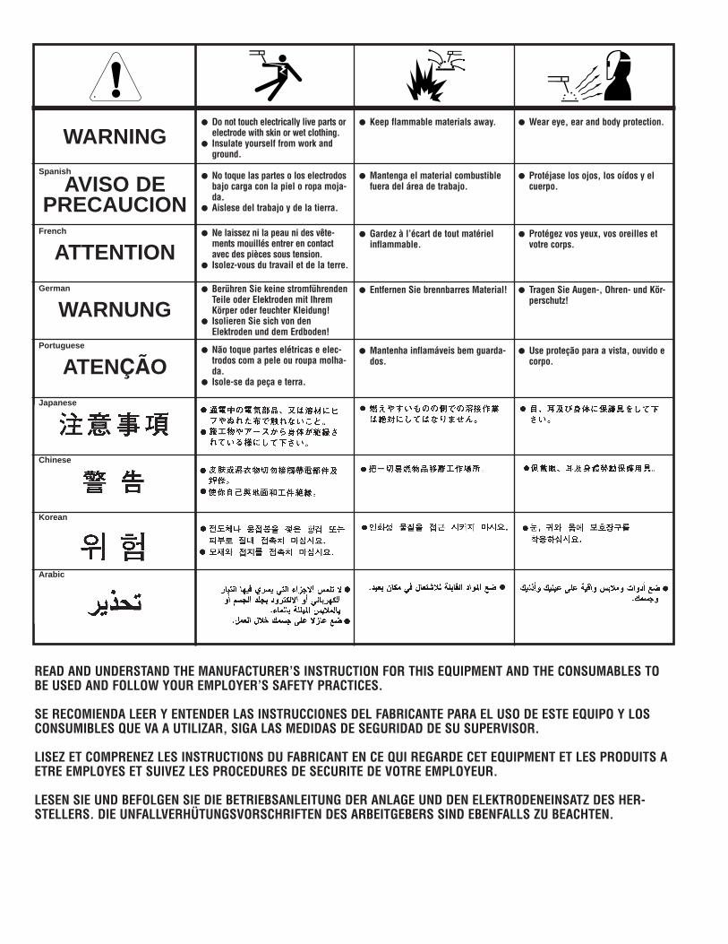
WARNING
AVISO DEPRECAUCION
ATTENTION
WARNUNG
ATENÇÃO
Spanish
French
German
Portuguese
Japanese
Chinese
Korean
Arabic
READ AND UNDERSTAND THE MANUFACTURER’S INSTRUCTION FOR THIS EQUIPMENT AND THE CONSUMABLES TOBE USED AND FOLLOW YOUR EMPLOYER’S SAFETY PRACTICES.
SE RECOMIENDA LEER Y ENTENDER LAS INSTRUCCIONES DEL FABRICANTE PARA EL USO DE ESTE EQUIPO Y LOSCONSUMIBLES QUE VA A UTILIZAR, SIGA LAS MEDIDAS DE SEGURIDAD DE SU SUPERVISOR.
LISEZ ET COMPRENEZ LES INSTRUCTIONS DU FABRICANT EN CE QUI REGARDE CET EQUIPMENT ET LES PRODUITS AETRE EMPLOYES ET SUIVEZ LES PROCEDURES DE SECURITE DE VOTRE EMPLOYEUR.
LESEN SIE UND BEFOLGEN SIE DIE BETRIEBSANLEITUNG DER ANLAGE UND DEN ELEKTRODENEINSATZ DES HER-STELLERS. DIE UNFALLVERHÜTUNGSVORSCHRIFTEN DES ARBEITGEBERS SIND EBENFALLS ZU BEACHTEN.
● Do not touch electrically live parts orelectrode with skin or wet clothing.
● Insulate yourself from work andground.
● No toque las partes o los electrodosbajo carga con la piel o ropa moja-da.
● Aislese del trabajo y de la tierra.
● Ne laissez ni la peau ni des vête-ments mouillés entrer en contactavec des pièces sous tension.
● Isolez-vous du travail et de la terre.
● Berühren Sie keine stromführendenTeile oder Elektroden mit IhremKörper oder feuchter Kleidung!
● Isolieren Sie sich von denElektroden und dem Erdboden!
● Não toque partes elétricas e elec-trodos com a pele ou roupa molha-da.
● Isole-se da peça e terra.
● Keep flammable materials away.
● Mantenga el material combustiblefuera del área de trabajo.
● Gardez à l’écart de tout matérielinflammable.
● Entfernen Sie brennbarres Material!
● Mantenha inflamáveis bem guarda-dos.
● Wear eye, ear and body protection.
● Protéjase los ojos, los oídos y elcuerpo.
● Protégez vos yeux, vos oreilles etvotre corps.
● Tragen Sie Augen-, Ohren- und Kör-perschutz!
● Use proteção para a vista, ouvido ecorpo.
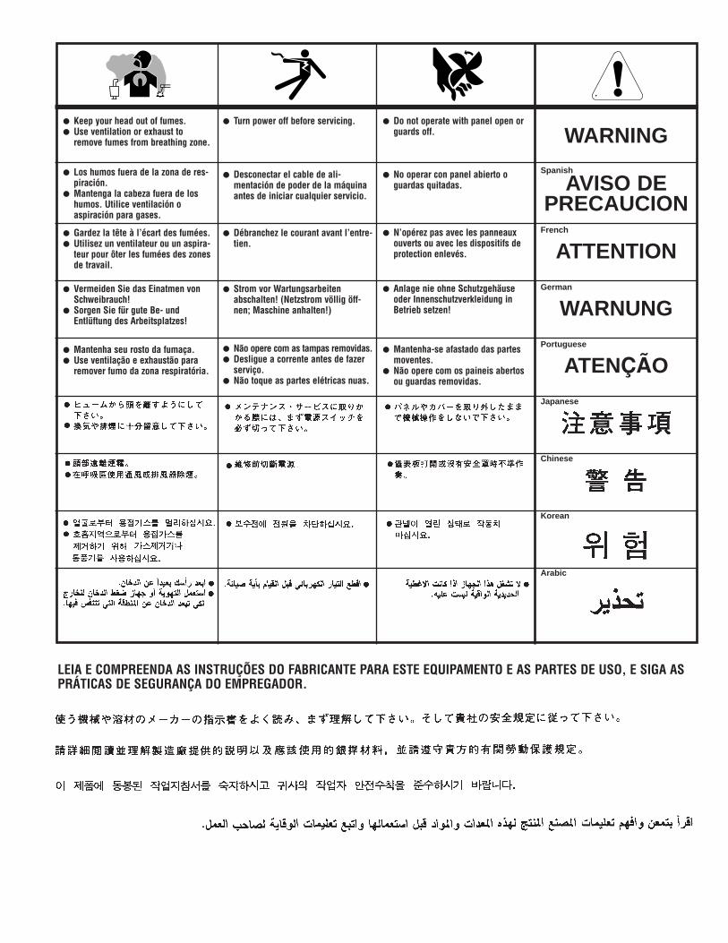
WARNING
AVISO DEPRECAUCION
ATTENTION
WARNUNG
ATENÇÃO
Spanish
French
German
Portuguese
Japanese
Chinese
Korean
Arabic
LEIA E COMPREENDA AS INSTRUÇÕES DO FABRICANTE PARA ESTE EQUIPAMENTO E AS PARTES DE USO, E SIGA ASPRÁTICAS DE SEGURANÇA DO EMPREGADOR.
● Keep your head out of fumes.● Use ventilation or exhaust to
remove fumes from breathing zone.
● Los humos fuera de la zona de res-piración.
● Mantenga la cabeza fuera de loshumos. Utilice ventilación oaspiración para gases.
● Gardez la tête à l’écart des fumées.● Utilisez un ventilateur ou un aspira-
teur pour ôter les fumées des zonesde travail.
● Vermeiden Sie das Einatmen vonSchweibrauch!
● Sorgen Sie für gute Be- undEntlüftung des Arbeitsplatzes!
● Mantenha seu rosto da fumaça.● Use ventilação e exhaustão para
remover fumo da zona respiratória.
● Turn power off before servicing.
● Desconectar el cable de ali-mentación de poder de la máquinaantes de iniciar cualquier servicio.
● Débranchez le courant avant l’entre-tien.
● Strom vor Wartungsarbeitenabschalten! (Netzstrom völlig öff-nen; Maschine anhalten!)
● Não opere com as tampas removidas.● Desligue a corrente antes de fazer
serviço.● Não toque as partes elétricas nuas.
● Do not operate with panel open orguards off.
● No operar con panel abierto oguardas quitadas.
● N’opérez pas avec les panneauxouverts ou avec les dispositifs deprotection enlevés.
● Anlage nie ohne Schutzgehäuseoder Innenschutzverkleidung inBetrieb setzen!
● Mantenha-se afastado das partesmoventes.
● Não opere com os paineis abertosou guardas removidas.

• Sales and Service through Subsidiaries and Distributors Worldwide •Cleveland, Ohio 44117-1199 U.S.A. TEL: 216.481.8100 FAX: 216.486.1751 WEB SITE: www.lincolnelectric.com
• World's Leader in Welding and Cutting Products •