dc circuit breakers - top and tail · dc circuit breakers . background . multi-terminal hvdc...
TRANSCRIPT
DC Circuit Breakers
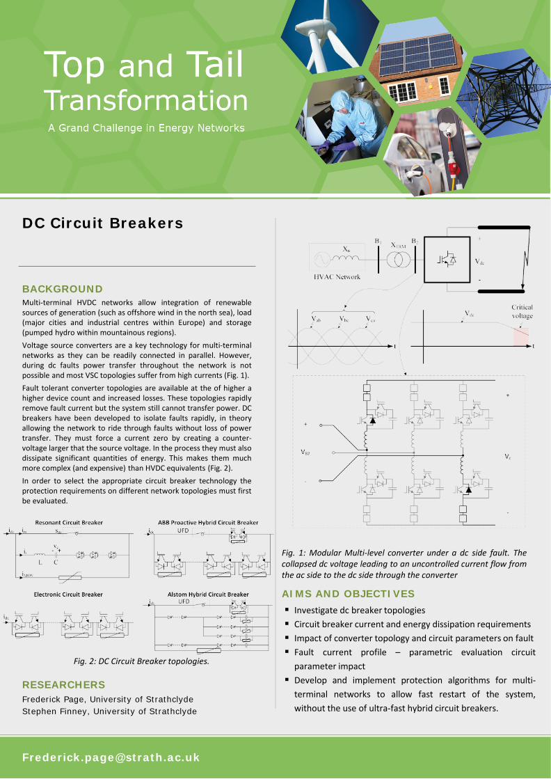
BACKGROUND Multi-terminal HVDC networks allow integration of renewable sources of generation (such as offshore wind in the north sea), load (major cities and industrial centres within Europe) and storage (pumped hydro within mountainous regions). Voltage source converters are a key technology for multi-terminal networks as they can be readily connected in parallel. However, during dc faults power transfer throughout the network is not possible and most VSC topologies suffer from high currents (Fig. 1). Fault tolerant converter topologies are available at the of higher a higher device count and increased losses. These topologies rapidly remove fault current but the system still cannot transfer power. DC breakers have been developed to isolate faults rapidly, in theory allowing the network to ride through faults without loss of power transfer. They must force a current zero by creating a counter-voltage larger that the source voltage. In the process they must also dissipate significant quantities of energy. This makes them much more complex (and expensive) than HVDC equivalents (Fig. 2). In order to select the appropriate circuit breaker technology the protection requirements on different network topologies must first be evaluated.
Fig. 1: Modular Multi-level converter under a dc side fault. The collapsed dc voltage leading to an uncontrolled current flow from the ac side to the dc side through the converter
RESEARCHERS Frederick Page, University of Strathclyde Stephen Finney, University of Strathclyde
AIMS AND OBJECTIVES
Investigate dc breaker topologies Circuit breaker current and energy dissipation requirements Impact of converter topology and circuit parameters on fault Fault current profile – parametric evaluation circuit
parameter impact Develop and implement protection algorithms for multi-
terminal networks to allow fast restart of the system, without the use of ultra-fast hybrid circuit breakers.
Fig. 2: DC Circuit Breaker topologies.

ACHIEVEMENTS An average value modular multi-level converter model has been developed and used for fault profiling and parametric evaluations of circuit breaker stress. Analytical tools have been developed to estimate the stress that the circuit breaker is placed under, these have then been validated against simulated results (Fig. 3). Fault detection algorithms have been developed to protect the converter as soon as possible by blocking the IGBTs. A separate controller has been developed for the converter restart, following unblocking. The routine assists in stabilising the grid after the large transients experienced after fault clearing, reducing the restart time. Multi-terminal network models have been used to evaluate different protection schemes and algorithms to minimise the system restart time. Simulation results have shown that MMC based HVDC networks and resonant (cheaper but slower than ultra-fast resonant topologies) can be restarted in time-frames comparable fault clearing within HVAC networks (Fig. 4).
IMPACT The work carried out as part of the top and tail project has increased understanding on the development of fault currents within HVDC networks, in particular modular multi-level converters. It has highlighted the critical components of the system that require protection and those that do not. It has been shown that the converters can withstand the high fault currents associated with dc faults when cleared with relatively slow resonant circuit breakers (but with a significantly lower cost than ultra-fast hybrid types). The use of slower dc breakers causes the dc voltage to collapse throughout the system. However, simulation results have shown that it is feasible to restore multi-terminal networks within in a short space of time (approximately 120ms)
Output from the project has been fed into the Cigre joint working group A3/B4.34 (High Voltage DC switchgear) technical brochure. Contributions include dc breaker theory fault current profiling and system operation.
Fig. 3: Estimated peak current through a dc breaker contrasted with results from simulation
Publications:
‘DC fault parameter sensitivity analysis’: Development in Power System Protection (DPSP), Copenhagen 2014
‘An alternative protection strategy for multi-terminal HVDC’: Wind Integration Workshop, Berlin 2014
‘Optimisation of passive system components to minimise stress in multi-terminal HVDC systems’: Cigre Across boarders symposium, Lund 2015
Fig. 4: Example three-terminal network used to demonstrate fault ride through