dc circuits. emf and terminal voltage electric circuit needs a battery or generator to produce...
TRANSCRIPT
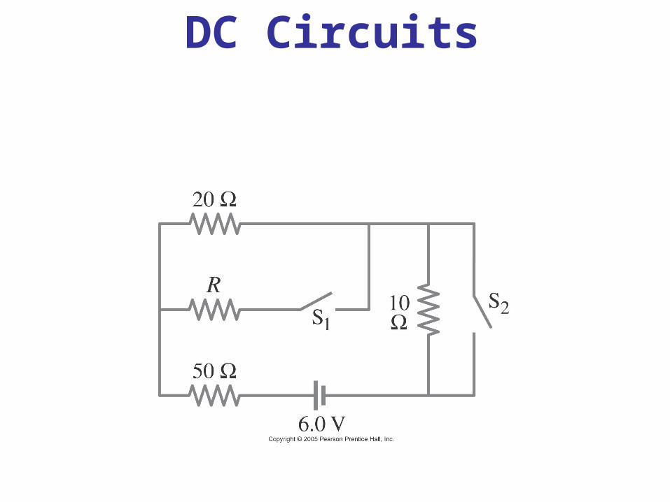
DC Circuits
EMF and Terminal Voltage
Electric circuit needs a battery or generator to produce current – these are called sources of emf.
Battery is a nearly constant voltage source, but does have a small internal resistance, which reduces the actual voltage from the ideal emf:

EMF and Terminal Voltage
This resistance behaves as though it were in series with the emf.

Resistors in Series and in Parallel
A series connection has a single path from the battery, through each circuit element in turn, then back to the battery.
Resistors in Series and in Parallel
The current through each resistor is the same; the voltage depends on the resistance. The sum of the voltage drops across the resistors equals the battery voltage.

Resistors in Series and in Parallel
From this we get the equivalent resistance (that single resistance that gives the same current in the circuit).

Resistors in Series and in Parallel
A parallel connection splits the current; the voltage across each resistor is the same:

Resistors in Series and in Parallel
The total current is the sum of the currents across each resistor:

Resistors in Series and in Parallel
This gives the reciprocal of the equivalent resistance:

Resistors in Series and in Parallel
An analogy using water may be helpful in visualizing parallel circuits:

EMFs in Series and in Parallel; Charging a Battery
EMFs in series in the same direction: total voltage is the sum of the separate voltages

EMFs in Series and in Parallel; Charging a Battery
EMFs in series, opposite direction: total voltage is the difference, but the lower-voltage battery is charged.

EMFs in Series and in Parallel; Charging a Battery
EMFs in parallel only make sense if the voltages are the same; this arrangement can produce more current than a single emf.

Circuits Containing Capacitors in Series and in Parallel
Capacitors in parallel have the same voltage across each one:

Circuits Containing Capacitors in Series and in Parallel
In this case, the total capacitance is the sum:
Circuits Containing Capacitors in Series and in Parallel
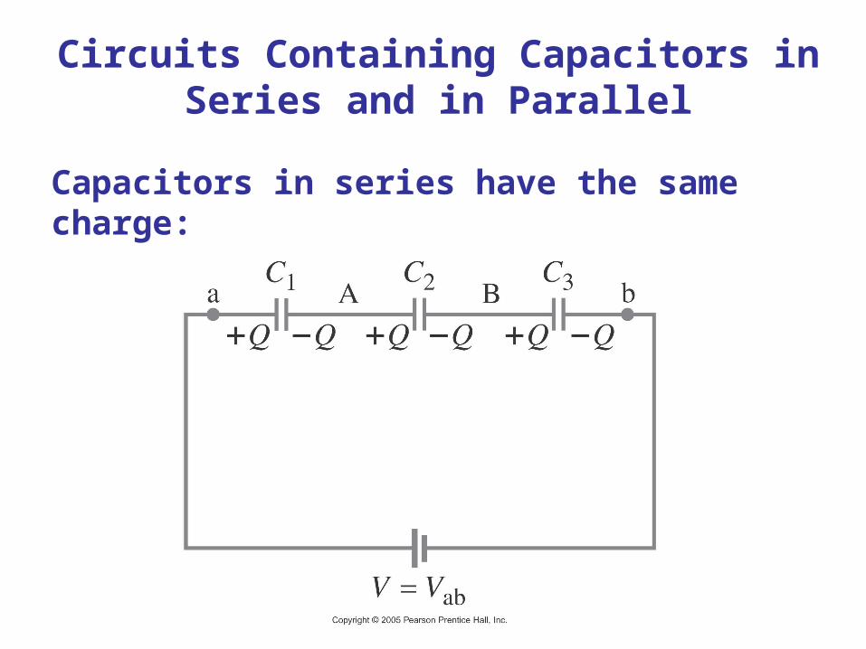
Capacitors in series have the same charge:
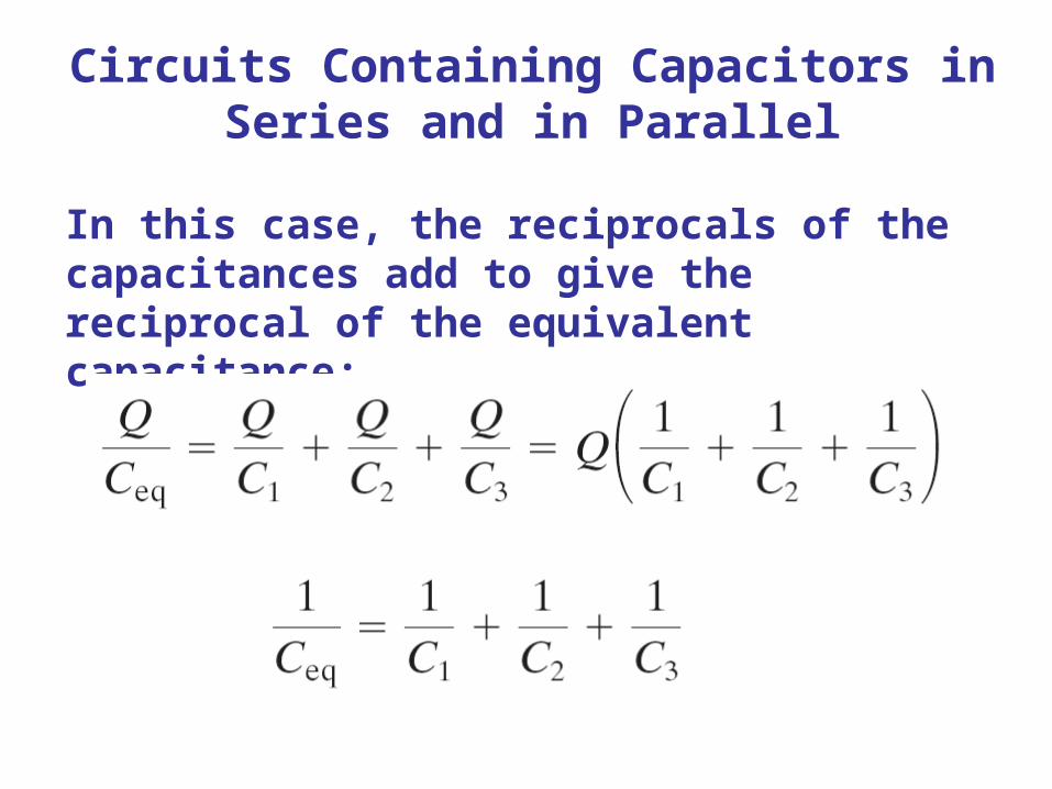
Circuits Containing Capacitors in Series and in Parallel
In this case, the reciprocals of the capacitances add to give the reciprocal of the equivalent capacitance:

RC Circuits – Resistor and Capacitor in Series
When the switch is closed, the capacitor will begin to charge.

RC Circuits – Resistor and Capacitor in Series
The voltage across the capacitor increases with time:
This is a type of exponential.

RC Circuits – Resistor and Capacitor in Series
This curve has a characteristic time constant:
The charge follows a similar curve:

RC Circuits – Resistor and Capacitor in Series
If an isolated charged capacitor is connected across a resistor, it discharges:

Ammeters and Voltmeters
An ammeter measures current; a voltmeter measures voltage. Both are based on galvanometers, unless they are digital.
The current in a circuit passes through the ammeter; the ammeter should have low resistance so as not to affect the current.

Ammeters and Voltmeters
A voltmeter should not affect the voltage across the circuit element it is measuring; therefore its resistance should be very large.

Ammeters and Voltmeters
If the meter has too much or (in this case) too little resistance, it can affect the measurement.