dc machines
DESCRIPTION
LessonTRANSCRIPT
DC MACHINESDC MACHINES
UNIT 5UNIT 5
Introduction Introduction
►Electrical machines means transfer the Electrical machines means transfer the energy from one form to other, either energy from one form to other, either from mechanical to electrical form or from mechanical to electrical form or electrical to mechanicalelectrical to mechanical
►DC machines are divided into two DC machines are divided into two typestypes
DC GeneratorDC Generator
DC Motor DC Motor

DC GeneratorDC Generator
It is converted to It is converted to mechanicalmechanical energy into energy into electrical electrical energyenergy
Mechanical Input
Electrical Output

DC MOTORDC MOTOR
►It is converted to electrical It is converted to electrical energy into mechanical energy into mechanical energy energy
Electrical Input
Mechanical Output

Construction of DC machinesConstruction of DC machinesDC machines (Generator & Motor ) have a two parts. (i) Stator
(ii) RotorStator consists of
(i) yoke or magnetic frame(ii) Field system: poles, field winding,
interpoles Rotor consists of
(i) Armature: Armature core, Armature winding
(ii) Commutator(iii) Brushes, bearings

(i) Yoke or Magnetic Frame: It provides mechanical support for the poles To protecting cover for the whole machine It is made up of cast iron or silicon steel
(good mechanical strength ) (ii) Field System: It consists of two main parts
(i) pole core (ii) pole shoe
Pole core carries field winding and produce the flux.
Pole shoes are used to reduce the reluctance.
It is made up of cast iron or cast steel.
Field winding: it is placed on the pole core To carry the current and to produce the
magnetic flux. It is made up of aluminium or copper(iii) ArmatureIt is divided by two parts
(i) armature core(ii) armature winding
Armature core: It is cylindrical Shape. It is mounted on the shaft.
It provides the houses for the armature conductors.It is made up of cast iron or cast steel.
Armature winding: Armature winding are placed into the slots on the armature
surface. End of coils are soldered with commutator segments It is made up of copper
commutator: It is used to collect the current from the armature conductor. To convert AC to DC It is made up of copper segments
Brushes and Bearings: Brush is used to collect current from commutator. It is made up of carbon or graphite. Ball Bearing and Roller Bearing. Roller bearings are employed in
heavy duty machines.

DC machines stator with poles visible
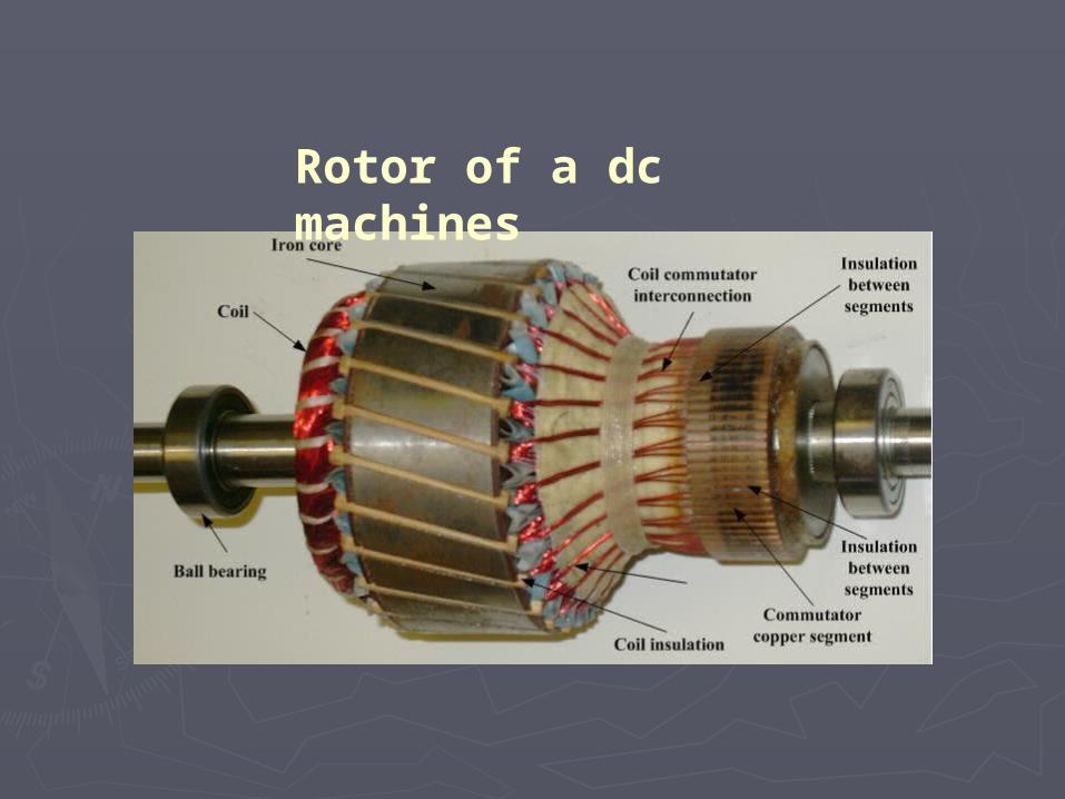
Rotor of a dc machines

Cutaway view of a dc machines

Principle of operation

It operates based on Faraday’s law of electromagnetic induction.
According to faraday’s law, when ever conductor cuts the magnetic flux lines, induced emf produced in the conductor.
The direction of current flow is found by Fleming’s right hand rule.

Types of Armature windings
Methods of placing armature conductorSingle layer winding: only one conductor is placed in each
armature slot. This is not mostly usedDouble layer winding: There are two conductors placed in
each armature slot

Methods of connecting the armature conductor
Lap winding: High current, Low voltage No. of parallel paths (A) =No. of poles (P)Wave winding: Low current, High voltage No. of parallel paths (A) = 2(always)

EMF equationLet
Ø= flux/pole in WbZ = total number of armature conductorsP = number of polesA = number of parallel paths = 2 … for wave winding
= P … for lap windingN = speed of armature in r.p.m.Eg= e.m.f. of the generator = e.m.f./parallel path
Average emf generated per conductor = volt

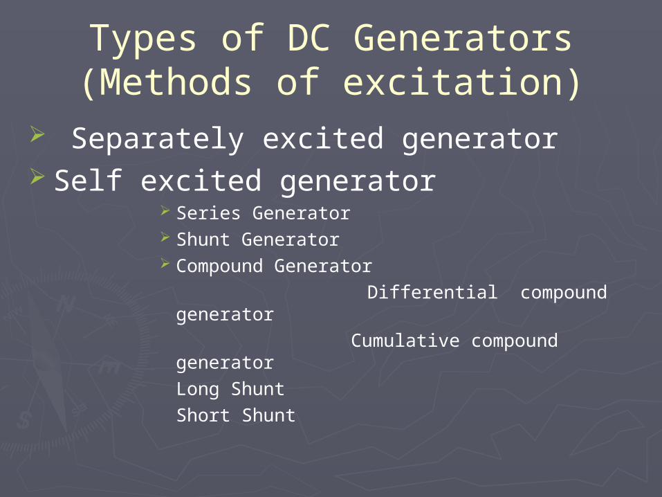
Types of DC Generators(Methods of excitation)
Separately excited generator Self excited generator
Series Generator Shunt Generator Compound Generator Differential compound generator
Cumulative compound generatorLong
ShuntShort
Shunt

Separately Excited DC generator
►Voltage equation: Eg=V+ IaRa►Current equation: Ia=IL
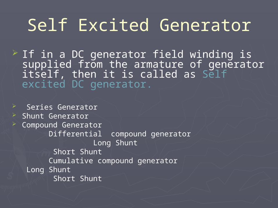
Self Excited Generator
If in a DC generator field winding is supplied from the armature of generator itself, then it is called as Self excited DC generator.
Series Generator Shunt Generator Compound Generator Differential compound generator
Long Shunt Short Shunt
Cumulative compound generator Long Shunt
Short Shunt

Series Generator
► Voltage equation: Eg=V+ IaRa+IseRse Eg=V+ Ia(Ra+Rse)
► Current equation: Ia=IL=Ise

Shunt Generator
►Voltage equation: Eg=V+ IaRa►Current equation: Ia=IL+Ish

Compound generator
Cumulative compound generator
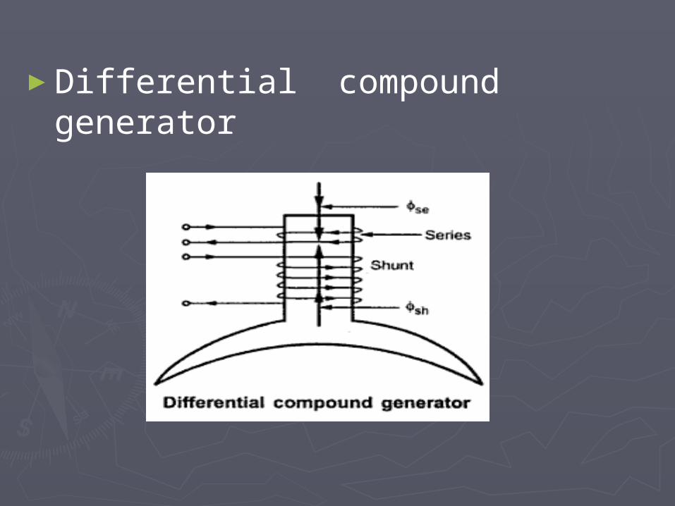
►Differential compound generator

Long Shunt compound Generator
Voltage equation: Eg=V+ Ia(Ra+Rse)Current equation: Ia=Ise=IL+Ish

Short Shunt compound Generator
►Voltage equation: Eg=V+ IaRa+ILRse►Current equation: Ia=IL+Ish IL=Ise
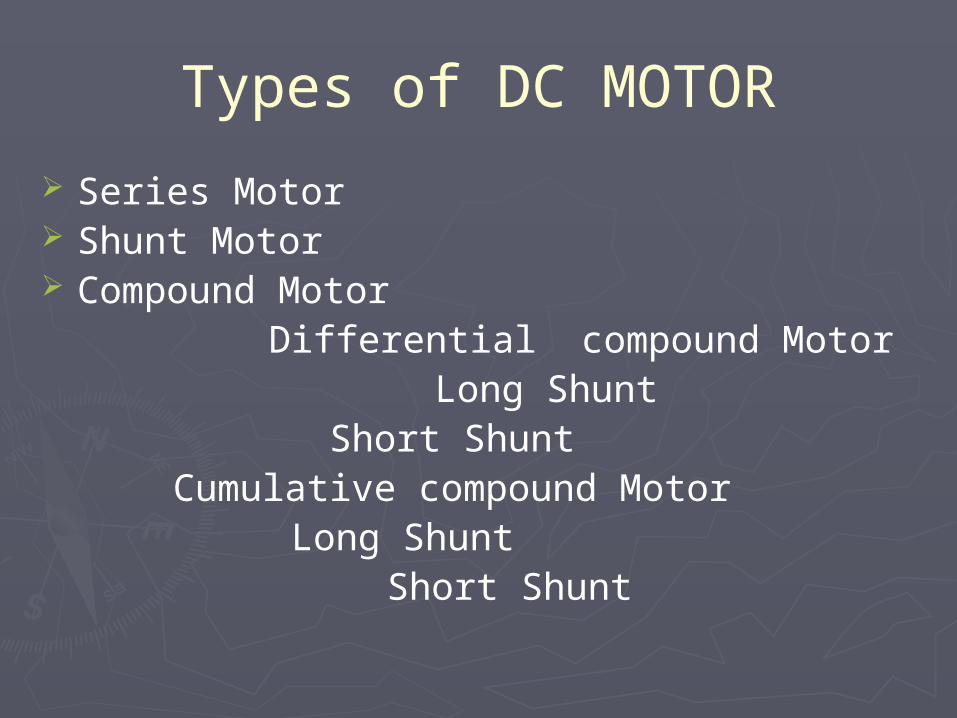
Types of DC MOTOR
Series Motor Shunt Motor Compound Motor Differential compound Motor
Long Shunt Short Shunt
Cumulative compound Motor Long Shunt
Short Shunt

Series Motor
► Voltage equation: V= Eb+ IaRa+ILRse V= Eb+ Ia(Ra+Rse)
► Current equation: Ia=IL=Ise

Shunt Motor
►Voltage equation: V= Eb+ IaRa
►Current equation: Ia=IL-Ish

Compound Motor
►Cumulative compound: To add the series field flux and shunt field
flux.

►Differential Compound Motor:
Difference between the series field flux and shunt field flux.

Long Shunt Compound Motor
►Voltage equation: V= Eb+ Ia(Ra+Rse)
►Current equation: Ia=Ise► IL=Ia+Ish

Short Shunt Compound Motor
►Voltage equation: V= Eb+ IaRa+ILRse)
►Current equation: IL=Ise► IL=Ia+Ish

Characteristics of DC motor
►Three characteristics curves of DC Motor are:
►Electrical Characteristics: Torque Vs Armature current (Ta/Ia).Speed Vs Armature current (N/Ia).
►Mechanical Characteristics: Speed vs Torque (N/Ta).

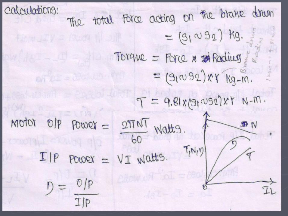
►In any motor, Torque: Torque(T) =
(0.159*ΦZPIa)/A
Ta Φ Ia.
0.159ZP/A= K(constant)
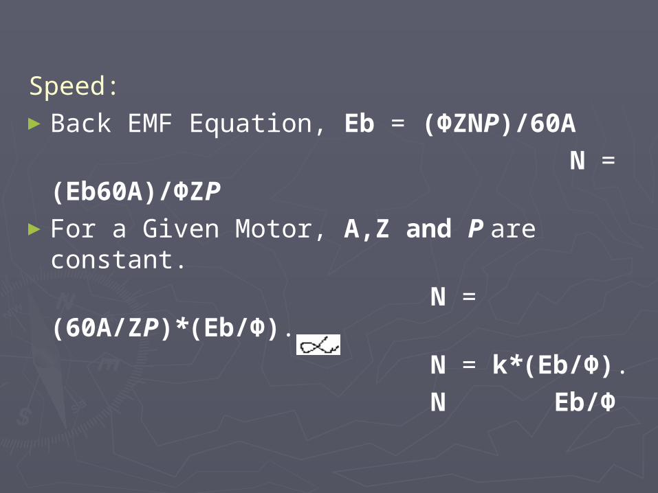
Speed:►Back EMF Equation, Eb = (ΦZNP)/60A N =
(Eb60A)/ΦZP►For a Given Motor, A,Z and P are
constant. N = (60A/ZP)*(Eb/Φ). N = k*(Eb/Φ). N Eb/Φ

Characteristics of DC Shunt Motor
Ta/Ia : ►Flux Φ is constant (always). ►Ta Ia► Ta = K*Ia.
Ta
Ia

N/Ia:► Flux is constant. ►N Eb/Φ.►N = K* Eb.
Ia
N
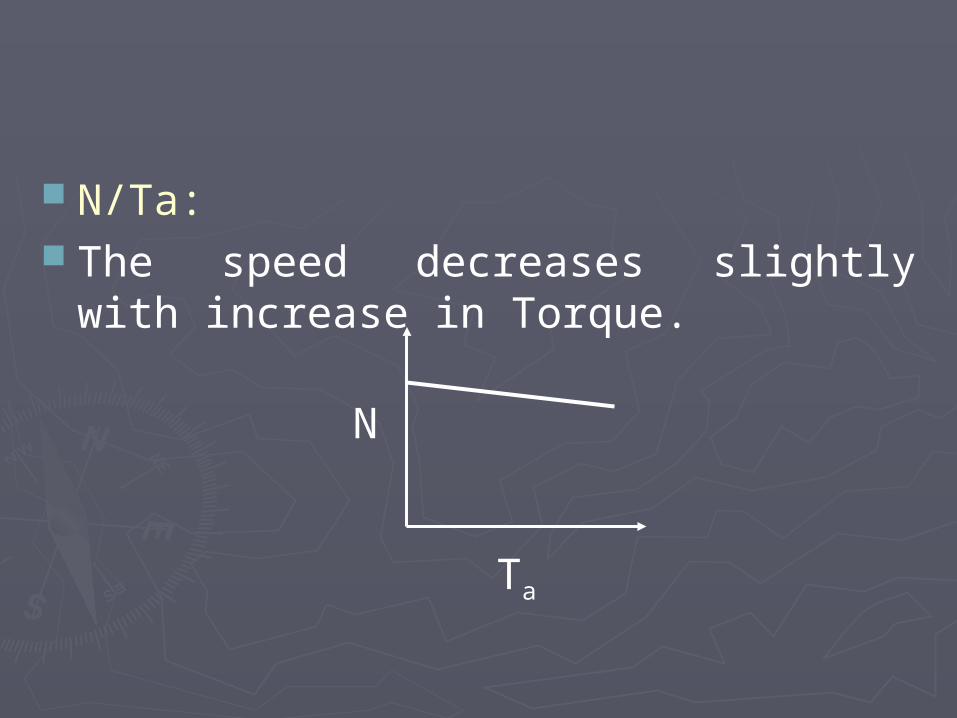
N/Ta: The speed decreases slightly with
increase in Torque.
N
Ta

Characteristics of DC Series Motor
Ta/Ia : ►Ta Φ Ia.►Flux Φ Ia ►Ta = K*Ia2.
Ia
Ta

N/Ia:► Flux is constant. N Eb/Φ.►But in series motor, Φ Ia.
N
Ia
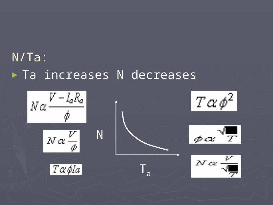
N/Ta:►Ta increases N decreases
N
Ta

Characteristics of DC Compound Motor

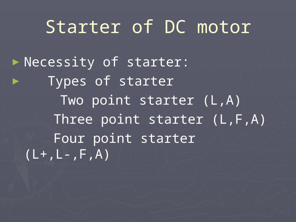
Starter of DC motor
►Necessity of starter:► Types of starter Two point starter (L,A)
Three point starter (L,F,A) Four point starter (L+,L-,F,A)

Necessity of starter
►To safely run a DC Motor►At the time of starting back EMF is
zero and armature current is very high.
►Due to the very high current the motor gets damaged.
►To reduce the starting current of the motor a starter is used.
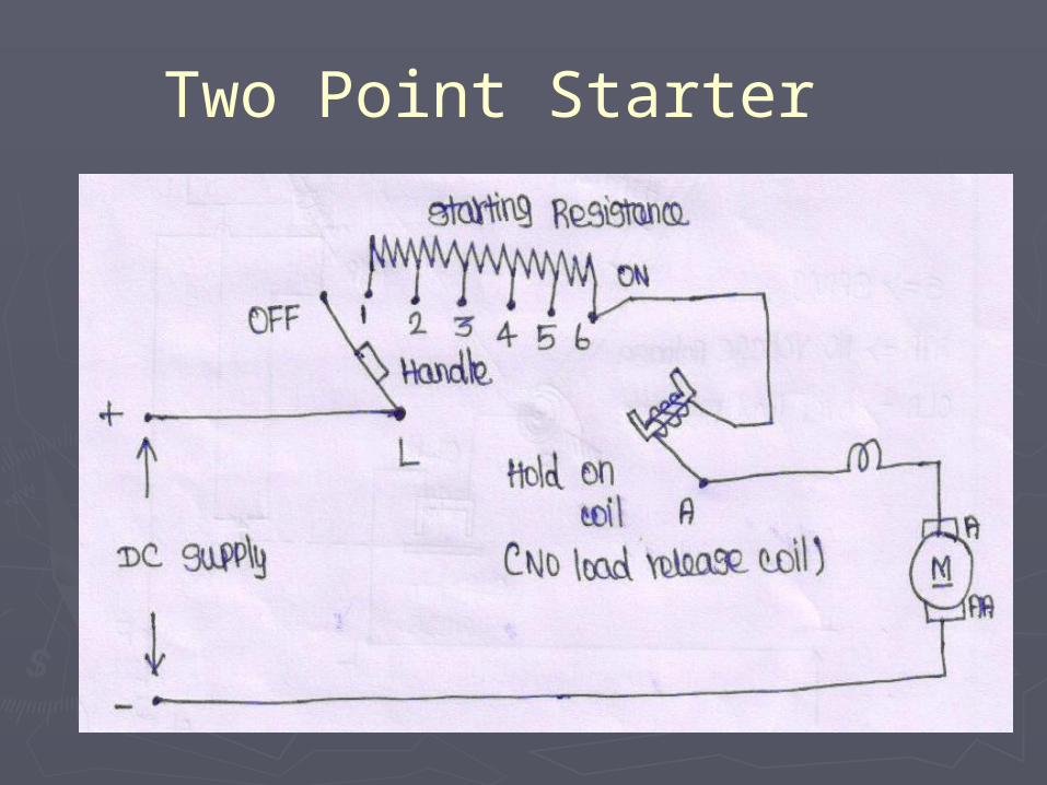
Two Point Starter

Three point starter

Four point starter

Power Flow diagram of D.C. Generator
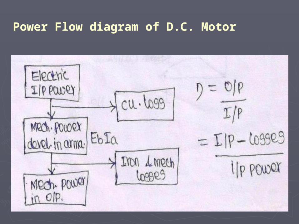
Power Flow diagram of D.C. Motor

Testing of D.C Machines
►Brake Test or Direct Load Test►Swinburn’s Test or No Load Test ►Hopkinson’s Test (or) Back to Back
Test
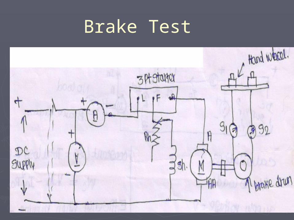
Brake Test

Swinburn’sTest
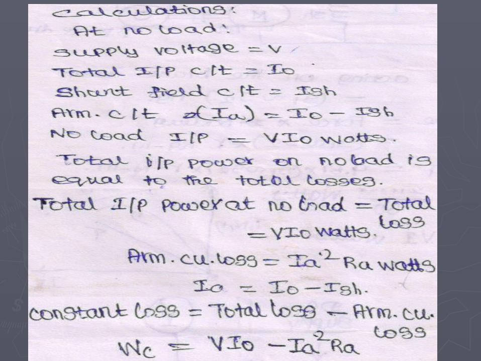

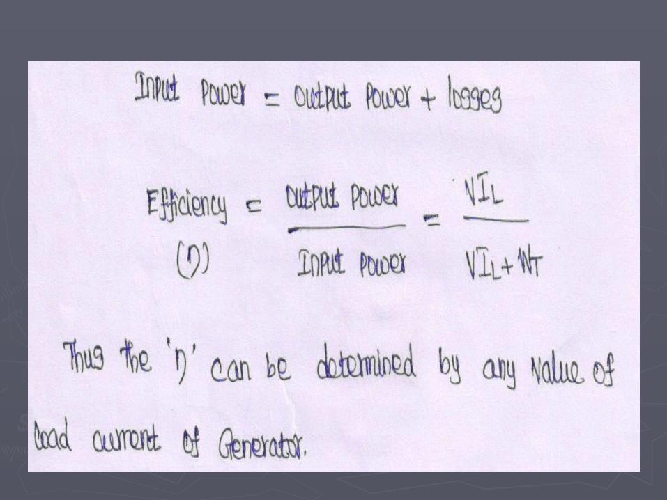
Efficiency Running as a Motor

Efficiency Running as a Generator

Hopkinson’s Test
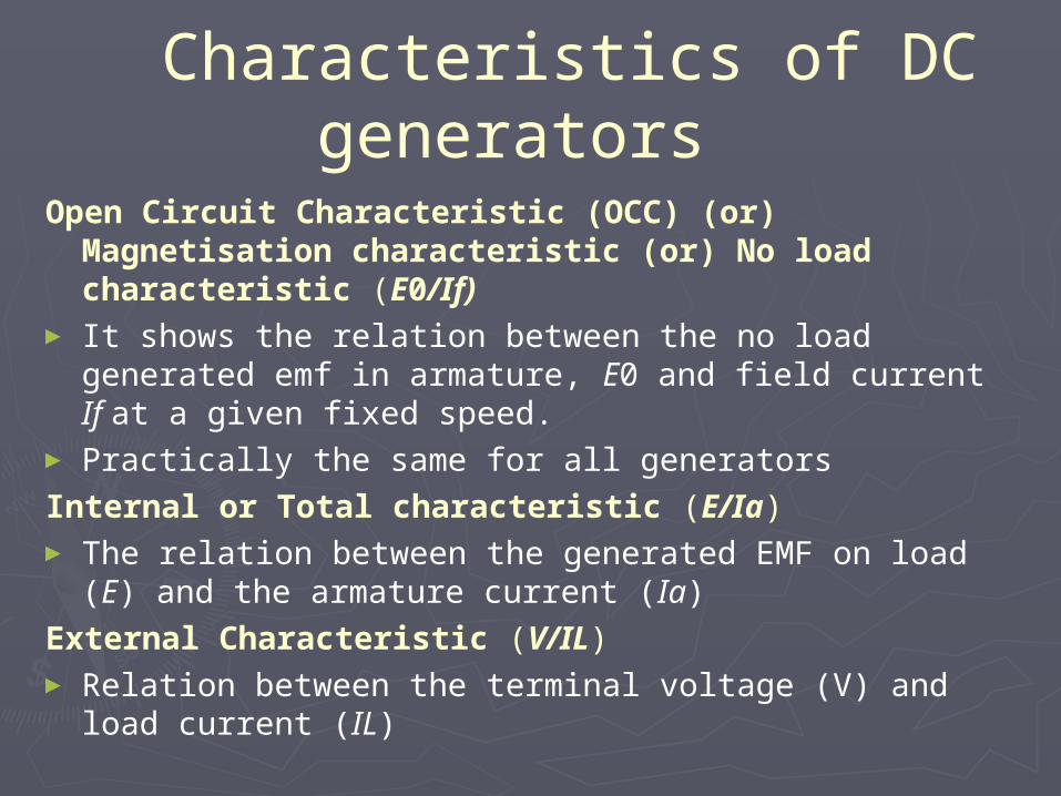
Characteristics of DC generators
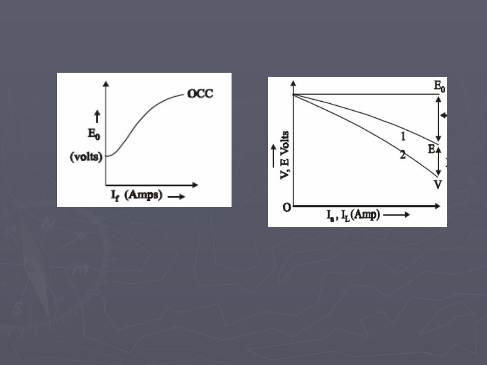
Open Circuit Characteristic (OCC) (or) Magnetisation characteristic (or) No load characteristic (E0/If)
► It shows the relation between the no load generated emf in armature, E0 and field current If at a given fixed speed.
► Practically the same for all generators
Internal or Total characteristic (E/Ia)► The relation between the generated EMF on load (E) and the
armature current (Ia)
External Characteristic (V/IL)► Relation between the terminal voltage (V) and load current (IL)
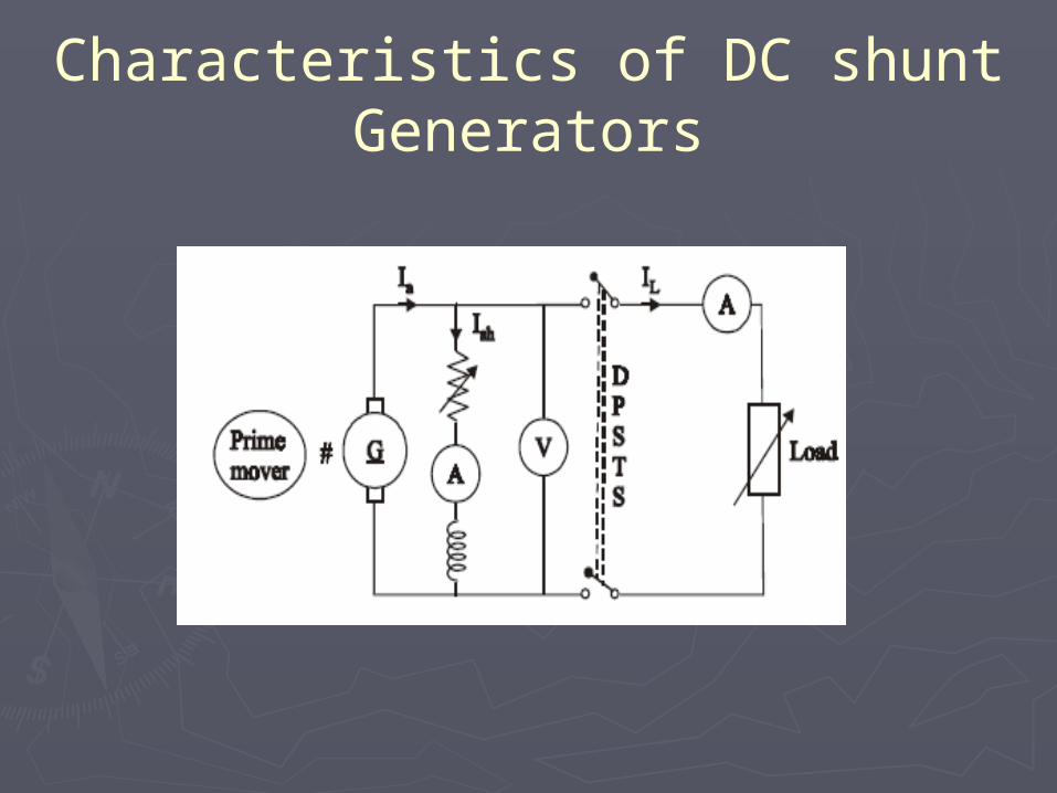
Characteristics of DC shunt Generators

Characteristics of Separately Excited DC Generators
Open Circuit Characteristic (OCC)
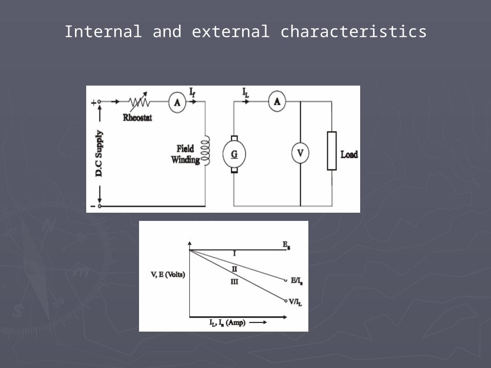
Internal and external characteristics

Characteristics of DC series Generators

Characteristics of DC Compound Generators

Cumulative compoundThis classification based upon the series field winding
►Over compound (series field winding turns adjusted, increase the load current, terminal voltage also increased)
► Flat compound (series field winding turns adjusted, increase the load current, terminal voltage approximately constant)
►Under compound (series field winding has less no. of turns than a flat compounded machine, load current increase, terminal voltage decreased)

Armature Reaction
►DC Motor has two windings (armature and field)
►Armature winding produce the armature flux
►Field winding produce the field flux.►Under load condition armature flux
disturb the main field flux called as Armature Reaction.

►GNA (Geometrical Neutral Axis):It is the line which bi sects the angle
between the two centers of adjacent poles.►MNA (Magnetic neutral axis)
It is the axis which is perpendicular to the magnetic flux lines.
This is the axis at which the brushes are placed.
► Leading Pole Tip (LPT)When armature rotated, its first contact of pole end called as LPT.
►Trailing Pole Tip (TPT) ►When armature rotated, its latterly contact of
pole end called as TPT.
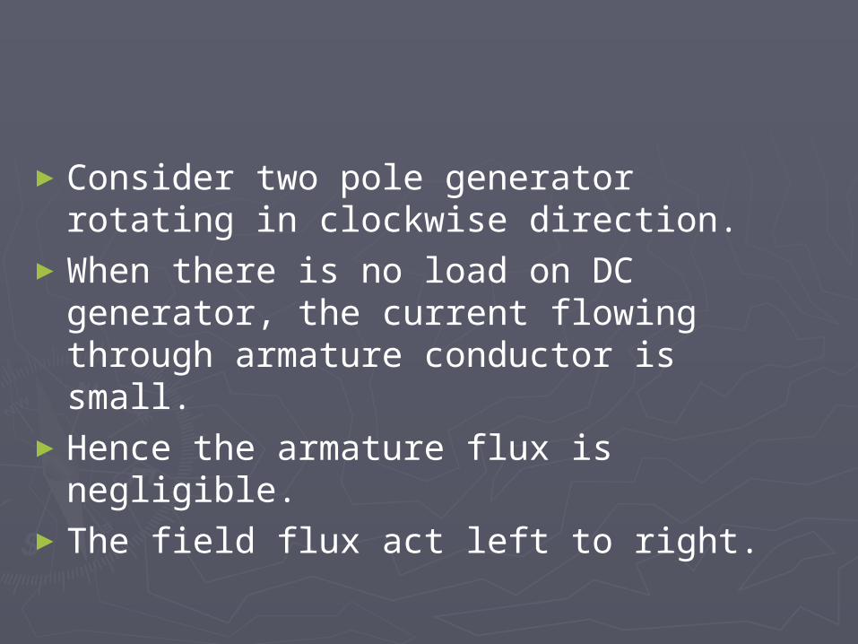
►Consider two pole generator rotating in clockwise direction.
►When there is no load on DC generator, the current flowing through armature conductor is small.
►Hence the armature flux is negligible.►The field flux act left to right.
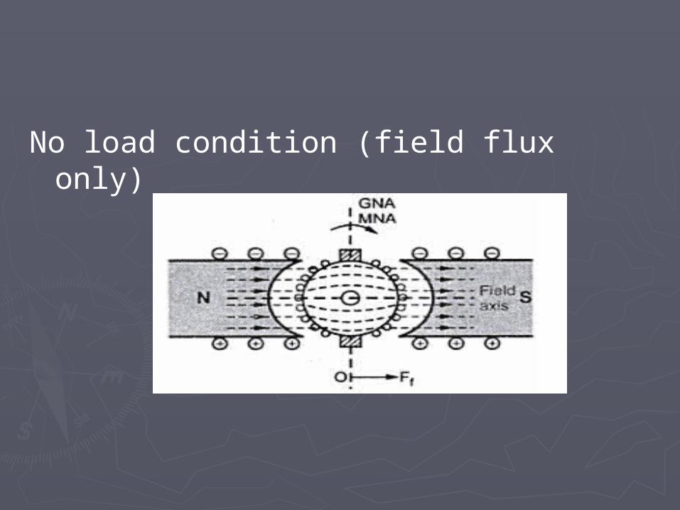
No load condition (field flux only)

►When the generator is loaded, armature winding produce the armature flux, if consider only armature flux, they act along the MNA axis (up to down ward direction)
Load condition (armature flux only)

► load condition, If we consider both the field flux and armature flux.
►They will be a perpendicular to each other.
Load Condition (Field & armature flux)
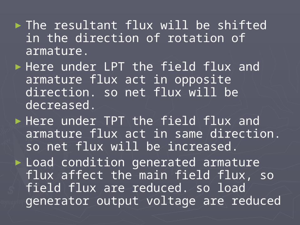
►The resultant flux will be shifted in the direction of rotation of armature.
►Here under LPT the field flux and armature flux act in opposite direction. so net flux will be decreased.
►Here under TPT the field flux and armature flux act in same direction. so net flux will be increased.
►Load condition generated armature flux affect the main field flux, so field flux are reduced. so load generator output voltage are reduced
Effect of Armature Reaction
►Main field flux are reduced►Causes heavy sparking on the
commutator►Generated output voltage reduced►Machine efficiency reduced►MNA shift sparking produced in brush.

Methods of Compensating Armature Reaction
►Increasing the air gap length►By providing inter poles (commutating
poles) ►By providing compensating winding

Increasing the air gap length
►By increasing the air gap length in small DC machines
►This increases the ratio of the pole M.M.F to the armature M.M.F.
►Thus the effect of armature reaction is reduced

By providing inter poles (commutating poles)
►By providing the commutating poles (inter poles) produces a flux opposite to the flux produced due to armature reaction and hence it gets neutralized.

By providing compensating winding
►These windings are connected in series with armature winding
►They carry the armature current but in the opposite direction to that in armature conductors.
►Establishing the flux will be neutralized

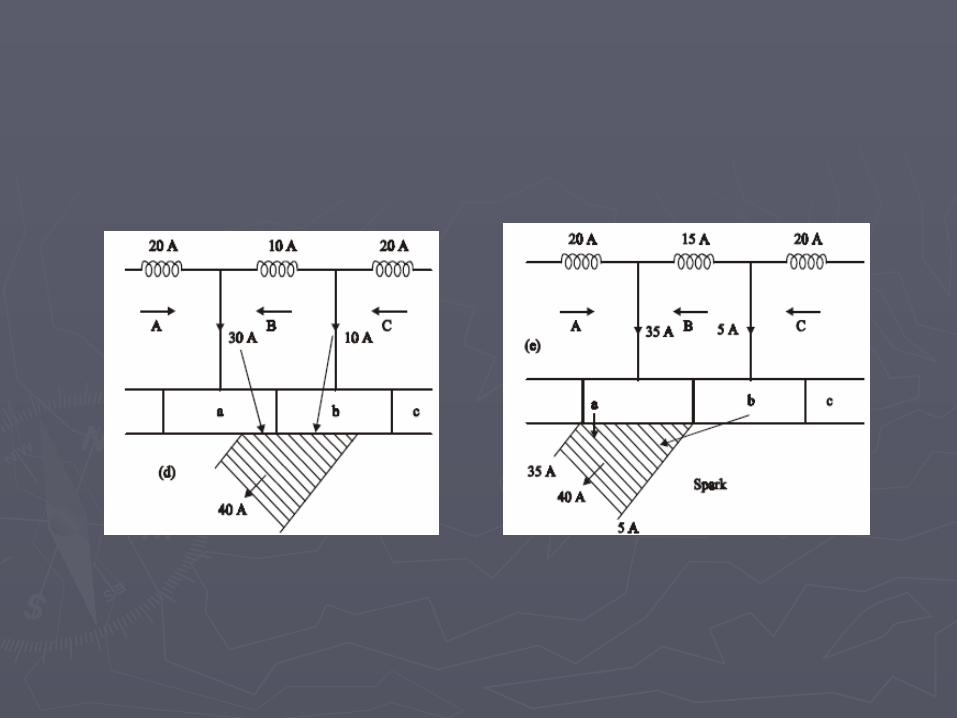
Commutation of DC Machines
► It is defined as the process of collecting current from the commutator in the short circuit coil during its transfer from one armature circuit to other
►The small period during which the coil remains short circuited by the brushes is known as the commutation period Tc
► If the current reversal is completed by the end of commutation period it is called ideal commutation

Process of commutation

Methods of improving commutation
►Resistance commutation►By interpoles (EMF Commutation)