dc modular power system (front cover) - bailey net 90 … infi90 documentation/dc...i-e96-508c ®...
TRANSCRIPT

®®
E96-508
DC Modular Power System
Process Control andAutomation Solutionsfrom Elsag Bailey Group

WARNING notices as used in this instruction apply to hazards or unsafe practices that could result inpersonal injury or death.
CAUTION notices apply to hazards or unsafe practices that could result in property damage.
NOTES highlight procedures and contain information that assists the operator in understanding theinformation contained in this instruction.
WARNING
INSTRUCTION MANUALSDO NOT INSTALL, MAINTAIN, OR OPERATE THIS EQUIPMENT WITHOUT READING, UNDERSTANDING,AND FOLLOWING THE PROPER Elsag Bailey INSTRUCTIONS AND MANUALS; OTHERWISE, INJURY ORDAMAGE MAY RESULT.
RADIO FREQUENCY INTERFERENCEMOST ELECTRONIC EQUIPMENT IS INFLUENCED BY RADIO FREQUENCY INTERFERENCE (RFI). CAU-TION SHOULD BE EXERCISED WITH REGARD TO THE USE OF PORTABLE COMMUNICATIONS EQUIP-MENT IN THE AREA AROUND SUCH EQUIPMENT. PRUDENT PRACTICE DICTATES THAT SIGNSSHOULD BE POSTED IN THE VICINITY OF THE EQUIPMENT CAUTIONING AGAINST THE USE OF POR-TABLE COMMUNICATIONS EQUIPMENT.
POSSIBLE PROCESS UPSETSMAINTENANCE MUST BE PERFORMED ONLY BY QUALIFIED PERSONNEL AND ONLY AFTER SECURINGEQUIPMENT CONTROLLED BY THIS PRODUCT. ADJUSTING OR REMOVING THIS PRODUCT WHILE IT ISIN THE SYSTEM MAY UPSET THE PROCESS BEING CONTROLLED. SOME PROCESS UPSETS MAYCAUSE INJURY OR DAMAGE.
AVERTISSEMENT
MANUELS D’OPÉRATIONNE PAS METTRE EN PLACE, RÉPARER OU FAIRE FONCTIONNER L’ÉQUIPEMENT SANS AVOIR LU,COMPRIS ET SUIVI LES INSTRUCTIONS RÉGLEMENTAIRES DE Elsag Bailey . TOUTE NÉGLIGENCE ÀCET ÉGARD POURRAIT ÊTRE UNE CAUSE D’ACCIDENT OU DE DÉFAILLANCE DU MATÉRIEL.
PERTURBATIONS PAR FRÉQUENCE RADIOLA PLUPART DES ÉQUIPEMENTS ÉLECTRONIQUES SONT SENSIBLES AUX PERTURBATIONS PARFRÉQUENCE RADIO. DES PRÉCAUTIONS DEVRONT ÊTRE PRISES LORS DE L’UTILISATION DU MATÉ-RIEL DE COMMUNICATION PORTATIF. LA PRUDENCE EXIGE QUE LES PRÉCAUTIONS À PRENDREDANS CE CAS SOIENT SIGNALÉES AUX ENDROITS VOULUS DANS VOTRE USINE.
PERTURBATIONS DU PROCÉDÉL’ENTRETIEN DOIT ÊTRE ASSURÉ PAR UNE PERSONNE QUALIFIÉE EN CONSIDÉRANT L’ASPECTSÉCURITAIRE DES ÉQUIPEMENTS CONTRÔLÉS PAR CE PRODUIT. L’AJUSTEMENT ET/OU L’EXTRAC-TION DE CE PRODUIT PEUT OCCASIONNER DES À-COUPS AU PROCÉDÉ CONTRÔLE LORSQU’IL ESTINSÉRÉ DANS UNE SYSTÈME ACTIF. CES À-COUPS PEUVENT ÉGALEMENT OCCASIONNER DESBLESSURES OU DES DOMMAGES MATÉREILS.
NOTICE
The information contained in this document is subject to change without notice.
Elsag Bailey, its affiliates, employees, and agents, and the authors and contributors to this publication specif-ically disclaim all liabilities and warranties, express and implied (including warranties of merchantability andfitness for a particular purpose), for the accuracy, currency, completeness, and/or reliability of the informationcontained herein and/or for the fitness for any particular use and/or for the performance of any material and/or equipment selected in whole or part with the user of/or in reliance upon information contained herein.Selection of materials and/or equipment is at the sole risk of the user of this publication.
This document contains proprietary information of Elsag Bailey, Elsag Bailey Process Automation, andis issued in strict confidence. Its use, or reproduction for use, for the reverse engineering, developmentor manufacture of hardware or software described herein is prohibited. No part of this document may bephotocopied or reproduced without the prior written consent of Elsag Bailey.

I-E96-508C
Preface
The 24/48 VDC Modular Power System supplies system andI/O power to the INFI 90® system. This manual explains howthe 24/48 VDC Modular Power System operates through sup-portive text, diagrams and flowcharts. It provides introductorymaterial and specific instructions for installation, operation,troubleshooting and maintenance of the system based on thefollowing:
• IECAB01 or IECAB03 system cabinets.
• IEPDS01 or IEPDS02 system power modules.
• IEPDF01 or IEPDF02 field power modules.
• IEPEP04 power entry panel.
• IEMMU01 or IEMMU02 module mounting unit.
• IEPMU01 or IEPMU02 power mounting unit.
This manual also provides information about module currentconsumption so the modular power system can be sized foryour application. This instruction covers only the 24/48 VDCModular Power System. For information on the AC modularpower system refer to the AC Modular Power System manual.
® INFI 90 is a registered trademark of Elsag Bailey Process Automation.

®
List of Effective Pages
Total number of pages in this instruction is 79, consisting of the following:
Page No. Change Date
Preface OriginalList of Effective Pages Original
iii through ix Original1-1 through 1-7 Original2-1 through 2-7 Original3-1 through 3-15 Original4-1 through 4-3 Original5-1 through 5-5 Original6-1 through 6-7 Original7-1 through 7-6 Original8-1 OriginalA-1 through A-2 OriginalB-1 through B-10 OriginalC-1 through C-3 OriginalD-1 through D-3 Original
Index-1 Original
When an update is received, insert the latest changed pages and dispose of the super-seded pages.
NOTE: On an update page, the changed text or table is indicated by a vertical bar in the outer mar-gin of the page adjacent to the changed area. A changed figure is indicated by a vertical bar in theouter margin next to the figure caption. The date the update was prepared will appear beside thepage number.
I-E96-508C

I-E96-508C
Safety Summary
GENERALWARNINGS
Equipment EnvironmentAll components, whether in transportation, operation or storage,must be in a noncorrosive environment.
Electrical Shock Hazard During MaintenanceDisconnect power or take precautions to insure that contact withenergized parts is avoided when servicing.
Special HandlingThis module uses electrostatic sensitive devices.
SPECIFICWARNINGS
Verify the main power and power entry panel circuit breakers areturned off before starting installation, retrofit, upgrade, or wiring pro-cedures. Failure to do so could result in severe or fatal shock. Donot turn the power on until the installation, retrofit, upgrade, or wiringprocedures are complete. (p. 3-4, 3-11, 7-5)
Do not remove the plastic covers on the module mounting unit back-plane. These covers protect against accidental contact with DC volt-age. Severe or fatal shock could result. (p. 3-10)
There are exposed DC connections inside the cabinet. Theseexposed electrical connections present a shock hazard that cancause injury or death. (p. 6-1)
Never clean electrical parts or components with the power on.Doing so exposes you to a fatal electrical shock hazard. (p. 6-1)
If input or output circuits are a shock hazard after disconnecting sys-tem power at the power entry panel, then the door of the cabinetcontaining these externally powered circuits must be marked with awarning stating that multiple power sources exist. (p. 6-1)
Wear eye protection whenever working with cleaning solvents.When removing solvents from printed circuit boards using com-pressed air, injury to the eyes could result from splashing solvent asit is blown off the printed circuit board. (p. 6-1)
Handle the module by surfaces other than the heat sink. The heatsink may be hot and may cause severe burns. (p. 7-4)
Allow five seconds for the line filter capacitors to discharge beforehandling the module after removal. Failure to do so could result insevere or fatal shock. (p. 7-4)
vii

Sommaire de Sécurité
®
AVERTISSEMENTD'ORDREGENERAL
Environment de l'EquipementNes pas soumettre les composantes a une atmosphere corrosivelors du transport, de l'entreposage ou de l'utilisation.
Risques de Chocs Electriques lor de l'EntretienS'assurer de debrancher l'alimentation ou de prende les precau-tions necessaires a eviter tout contact avec des composants sourstension lors de l'entretien.
Precautions de ManutentionCe module contient des composantes sensibles aux dechargeselectro-statiques.
AVERTISSEMENTD'ORDRE
SPECIFIQUE
Assurez-vous que le disjoncteur d'alimentation principal et le dis-joncteur de panneau d'entrée des alimentations sont éteints avantde procéder à l'installation, à la mise à jour, à l'extension ou aucâblage, dans le but d'éviter les chocs sérieux et même mortels. Nerétablissez pas l'alimentation tant que ces procédures ne sont pasterminées. (p. 3-4, 3-11, 7-5)
Ne retirez pas les couvercles de plastique situés sur le panneauarrière du châssis de montage des modules. Ces couvercles con-stituent une protection contre les contacts accidentels avec la ten-sion c.c., qui risquent de provoquer des chocs sérieux et mêmemortels. (p. 3-10)
Cette armoire comporte des connexions c.c. dénudées. Ces con-nexions électriques présentent un danger d'électrocution pouvantentraîner des blessures ou la mort. (p. 6-1)
Il ne faut jamais nettoyer des pièces ou des composants électriqueslorsqu'ils sont sous tension. Ceci présente un risque d'électrocutionfatale. (p. 6-1)
Si des circuits d'entrée ou de sortie sont alimentés à partir desources externes, ils présentent un risque de choc électrique mêmelorsque l'alimentation du système est débranchée du panneaud'entrée l'alimentation. Le cas échéant, un avertissement signalantla présence de sources d'alimentation multiples doit être apposé surla porte de l'armoire. (p. 6-1)
Portez toujours des lunettes de protection lorsque vous utilisez dessolvants de nettoyage. L'air comprimé servant à enlever le solvantdes cartes de circuits imprimés provoque des élaboussures qui ris-quent d'atteindre les yeux. (p. 6-1)
viii I-E96-508C

I-E96-508C
Sommaire de Sécurité (suite)
AVERTISSEMENTD'ORDRE
SPECIFIQUE
Le module diot être manipulé à l'aide de surfaces autres que le dis-sipatour thermique. Ce dernier resque d'être chaud et de provoquerdes brûlures sérieuses. (p. 7-4)
Aprés avoir retiré le module, laissez les condensateurs de filtresantiparasites se décharger pendant cinq secondes avant demanipuler celui-ci, afin d'éviter les chocs sérieux et même mortels.(p. 7-4)
ix

Table of Contents
I-E96-508C
Page
SECTION 1 - INTRODUCTION....................................................................................................1-1OVERVIEW ..................................................................................................................1-1INTENDED USER.........................................................................................................1-1HARDWARE DESCRIPTION..........................................................................................1-1
Power Entry Panel..................................................................................................1-1Fan Assembly ........................................................................................................1-1Power Modules.......................................................................................................1-2Module Mounting Unit ...........................................................................................1-2Power Mounting Unit .............................................................................................1-2
FEATURES...................................................................................................................1-2INSTRUCTION CONTENT .............................................................................................1-3HOW TO USE THIS MANUAL .......................................................................................1-3GLOSSARY OF TERMS AND ABBREVIATIONS .............................................................1-4NOMENCLATURE ........................................................................................................1-4REFERENCE DOCUMENTS..........................................................................................1-5SPECIFICATIONS.........................................................................................................1-5
SECTION 2 - DESCRIPTION AND OPERATION........................................................................2-1INTRODUCTION...........................................................................................................2-1POWER DISTRIBUTION................................................................................................2-1POWER ENTRY PANEL.................................................................................................2-3
DC Transfer Module...............................................................................................2-3Bus Monitor Module ..............................................................................................2-3
FAN ASSEMBLY ...........................................................................................................2-4MODULE MOUNTING UNIT..........................................................................................2-4POWER MOUNTING UNIT ............................................................................................2-4POWER MODULES ......................................................................................................2-4STATUS SIGNALS ........................................................................................................2-5
Power System Status .............................................................................................2-5Bus Voltage Status ................................................................................................2-6
POWER MODULE STATUS ...........................................................................................2-6USER ALARM OUTPUTS ..............................................................................................2-7
SECTION 3 - INSTALLATION .....................................................................................................3-1INTRODUCTION...........................................................................................................3-1UNPACKING AND INSPECTION ....................................................................................3-1
Special Handling....................................................................................................3-1General Handling...................................................................................................3-2
SYSTEM INSTALLATION...............................................................................................3-2IEPEP04 POWER ENTRY PANEL WIRING .....................................................................3-3
DC Transfer Module...............................................................................................3-6Bus Monitor Module ..............................................................................................3-7Fan Assembly ........................................................................................................3-9Power Modules.......................................................................................................3-9
IEPMU01/02 POWER MOUNTING UNIT INSTALLATION .............................................3-11Required Tools .....................................................................................................3-11Installing the PMU in the INFI 90 Cabinet ............................................................3-12Wiring Instructions ..............................................................................................3-12
SECTION 4 - OPERATING PROCEDURES................................................................................4-1INTRODUCTION...........................................................................................................4-1LED INDICATORS ........................................................................................................4-1
iii

Table of Contents (continued)
®
Page
SECTION 4 - OPERATING PROCEDURES (continued)DC Transfer Module .............................................................................................. 4-1Bus Monitor Module .............................................................................................. 4-2Power Module ........................................................................................................ 4-2
DC TRANSFER MODULE/BUS MONITOR MODULE REMOVAL DURING OPERATION . 4-2RECOMMENDED START-UP PROCEDURES ................................................................ 4-2
SECTION 5 - TROUBLESHOOTING...........................................................................................5-1INTRODUCTION .......................................................................................................... 5-1TROUBLESHOOTING DC MODULAR POWER SYSTEMS .............................................. 5-1
SECTION 6 - MAINTENANCE.....................................................................................................6-1INTRODUCTION .......................................................................................................... 6-1PREVENTIVE MAINTENANCE SCHEDULE................................................................... 6-2EQUIPMENT REQUIRED ............................................................................................. 6-3PREVENTIVE MAINTENANCE PROCEDURES .............................................................. 6-3
Cabinet Filter Cleaning/Replacement .................................................................... 6-3Checking Connections ........................................................................................... 6-4Checking Power Module Outputs ........................................................................... 6-4Power Entry Panel Inspection and Check ............................................................... 6-5Printed Circuit Board Cleaning .............................................................................. 6-6
General Cleaning and Washing........................................................................ 6-6Edge Connector Cleaning ................................................................................ 6-6
SECTION 7 - REPAIR/REPLACEMENT PROCEDURES ...........................................................7-1INTRODUCTION .......................................................................................................... 7-1SPARE PARTS.............................................................................................................. 7-1DC TRANSFER MODULE REPLACEMENT.................................................................... 7-2BUS MONITOR MODULE REPLACEMENT ................................................................... 7-2FAN ASSEMBLY REPLACEMENT ................................................................................. 7-3
Fuse...................................................................................................................... 7-3Fan Assembly........................................................................................................ 7-3
POWER MODULE REPLACEMENT............................................................................... 7-3Power Module ........................................................................................................ 7-3Fuse...................................................................................................................... 7-4
POWER ENTRY PANEL REPLACEMENT ....................................................................... 7-5
SECTION 8 - SUPPORT SUERVICES ........................................................................................8-1INTRODUCTION .......................................................................................................... 8-1REPLACEMENT PARTS AND ORDERING INFORMATION ............................................. 8-1TRAINING.................................................................................................................... 8-1TECHNICAL DOCUMENTATION................................................................................... 8-1
APPENDIX A - QUICK REFERENCE MATERIAL ..................................................................... A-1INTRODUCTION ..........................................................................................................A-1
APPENDIX B - MODULE POWER REQUIREMENTS ............................................................... B-1INTRODUCTION ..........................................................................................................B-1CALCULATING CURRENT REQUIREMENTS ................................................................B-1CALCULATING I/O CURRENT REQUIREMENTS ..........................................................B-4
iv I-E96-508C

I-E96-508C
Table of Contents (continued)
Page
APPENDIX B - MODULE POWER REQUIREMENTS (continued)SIZING THE MODULAR POWER SYSTEM.................................................................... B-5
For Systems with IEPDS01 or IEPDS02 Power Modules Only ................................ B-5System Calculation Example Using IEPDS01 or IEPDS02 Power Modules Only ..... B-7For Systems Using Both IEPDS01 and IEPDF01, or IEPDS02 and IEPDF02 PowerModules................................................................................................................ B-7System Calculation Example Using IEPDS01 and IEPDF01, or IEPDS02 and IEPDF02 Power Modules...................................................................................................... B-9
MAXIMUM POWER ENTRY PANEL CURRENT DRAW................................................. B-10
APPENDIX C - WIRING DIAGRAMS.......................................................................................... C-1INTRODUCTION.......................................................................................................... C-1
APPENDIX D - MODULAR POWER SYSTEM SIZING TABLES .............................................. D-1INTRODUCTION.......................................................................................................... D-1
List of Figures
No. Title Page
2-1. Block Diagram of Modular Power System with Module Mounting Unit ....................2-12-2. Block Diagram of Modular Power System with Power Mounting Unit ......................2-22-3. Block Diagram, Power Distribution to the PDS .......................................................2-52-4. Block Diagram, PDS Module Converter and Status Circuitry ..................................2-62-5. Status Signal Circuit Diagram................................................................................2-73-1. System Cabinet (Rear View)....................................................................................3-33-2. Circuit Breakers CB1/CB2 ....................................................................................3-43-3. DC Transfer Module Board Layout .........................................................................3-73-4. Bus Monitor Module Board Layout .........................................................................3-93-5. Power Module Board Layout...................................................................................3-93-6. Recommended Power Module Layout....................................................................3-103-7. Heat Shrink Tubing for 5 VDC Connection ...........................................................3-133-8. Heat Shrink Tubing for 24 VDC Connection .........................................................3-145-1. Troubleshooting Flowchart, DC Modular Power Systems ........................................5-3B-1. Power Output of One IEPDS01/02 Module ............................................................ B-6C-1. IEPEP04 System Cabinet Wiring Diagram (Module Mounting Unit) ........................ C-2C-2. IEPEP04 System Cabinet Wiring Diagram (Power Mounting Unit) .......................... C-3
v
No. Title Page
List of Tables
®
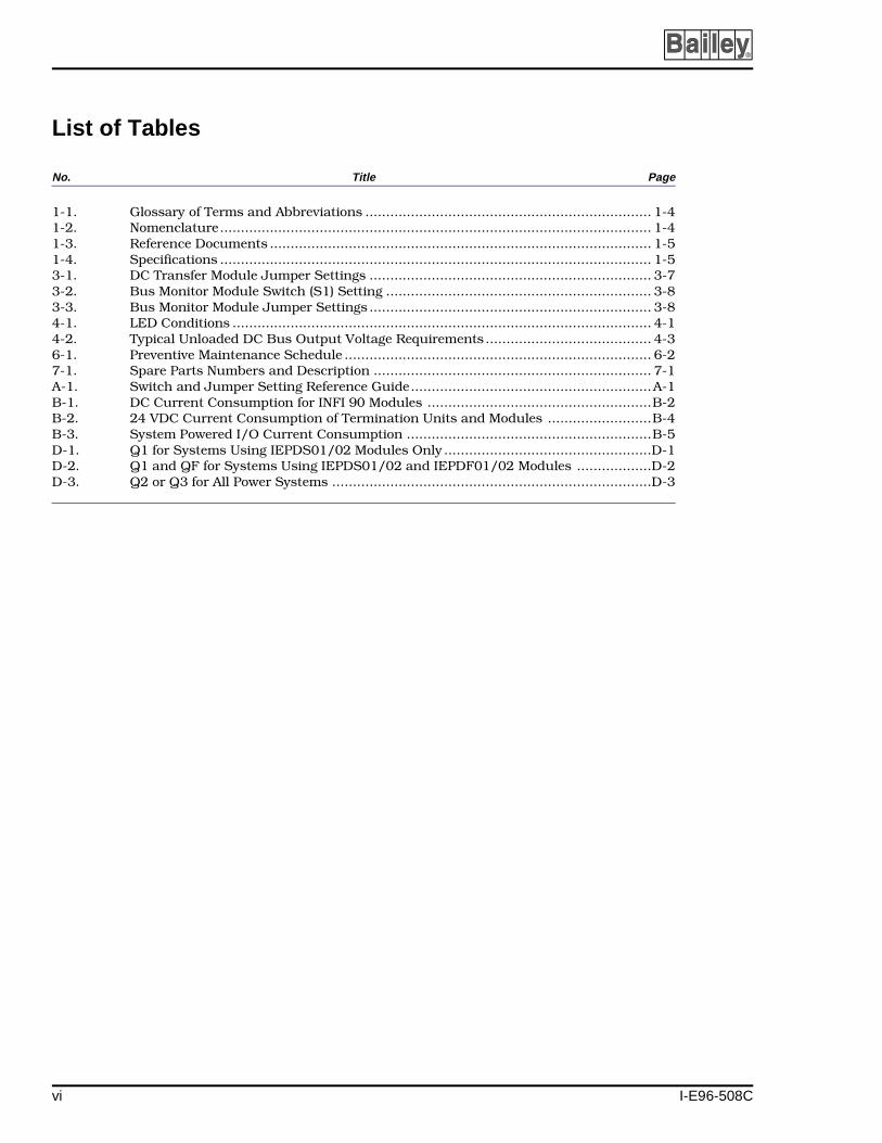
1-1. Glossary of Terms and Abbreviations ..................................................................... 1-41-2. Nomenclature........................................................................................................ 1-41-3. Reference Documents ............................................................................................ 1-51-4. Specifications ........................................................................................................ 1-53-1. DC Transfer Module Jumper Settings .................................................................... 3-73-2. Bus Monitor Module Switch (S1) Setting ................................................................ 3-83-3. Bus Monitor Module Jumper Settings .................................................................... 3-84-1. LED Conditions ..................................................................................................... 4-14-2. Typical Unloaded DC Bus Output Voltage Requirements ........................................ 4-36-1. Preventive Maintenance Schedule .......................................................................... 6-27-1. Spare Parts Numbers and Description ................................................................... 7-1A-1. Switch and Jumper Setting Reference Guide..........................................................A-1B-1. DC Current Consumption for INFI 90 Modules ......................................................B-2B-2. 24 VDC Current Consumption of Termination Units and Modules .........................B-4B-3. System Powered I/O Current Consumption ...........................................................B-5D-1. Q1 for Systems Using IEPDS01/02 Modules Only ..................................................D-1D-2. Q1 and QF for Systems Using IEPDS01/02 and IEPDF01/02 Modules ..................D-2D-3. Q2 or Q3 for All Power Systems .............................................................................D-3
vi I-E96-508C

SECTION 1 - INTRODUCTION
I-E96-508C
OVERVIEW
The INFI 90 DC input power system provides 5 VDC, ±15 VDC,and 24 VDC to power process control modules and field termi-nation devices. The DC input power system uses a 24 VDC or48 VDC input as the system supply voltage.
The system consists of the power entry panel (PEP), fan assem-bly, power modules and their mounting unit, bus bars andassociated wiring. The power modules provide scalable powerfor logic and I/O functions through N+1 redundancy. In thistype of redundancy, power modules equally share output. Ifany power module fails, the remaining power modules adjusttheir outputs to meet the total system load. Therefore, redun-dancy can be provided by one extra power module beyond theminimum number required to power the system.
INTENDED USER
The user should have a background in electricity and electron-ics and be able to recognize shock hazards. Personnel workingwith the DC modular power system must also be familiar withelectronic process control instrumentation and how to usemeasuring instruments such as digital multimeters.
HARDWARE DESCRIPTION
Power Entry Panel
The IEPEP04 Power Entry Panel supplies DC line power to thesystem cabinet. The IEPEP04 panel transfers redundant powerto the system cabinet and monitors system status. It containsthe DC transfer module and the bus monitor module whichperform these functions. The DC transfer module monitors linevoltage inputs to the system cabinet, provides automatic DCline transfer (for redundant DC lines) and generates a powerfail interrupt (PFI) signal. The bus monitor module monitorsthe power system and provides status and user alarm outputs.
Fan Assembly
The fan assembly provides air flow cooling for the power mod-ules and process control modules in the system cabinet. TheIEFAN03 fan assembly is used in 24 VDC powered systemsand the IEFAN05 fan assembly is used in 48 VDC poweredsystems.
OVERVIEW
1 - 1

INTRODUCTION ®
Power Modules
There are four power modules: the IEPDS01 System PowerModule and IEPDF01 Field Power Module require 24 VDCinputs, the IEPDS02 System Power Module and IEPDF02 FieldPower Module require 48 VDC inputs. The IEPDS01 andIEPDS02 modules provide 5 VDC, ±15 VDC and 24 VDC out-puts. The IEPDF01 and IEPDF02 modules provide only 24 VDCoutput for field powered devices.
Module Mounting Unit
The IEMMU01 Module Mounting Unit provides the housing,power connections and signal conductors for power supply andprocess control modules. The IEMMU02 Module Mounting Unithas the same functionality as the IEMMU01 Module MountingUnit, but it is a front-mounted unit. Its primary use is insmaller system cabinets like the MINI 90™ system.
Power Mounting Unit
The power mounting unit (PMU) segregates power modulesfrom INFI 90 process modules. It provides housing and powerconnections for IEPDS01 or IEPDS02 and IEPDF01 orIEPDF02 power modules. The PMU is capable of supporting upto 12 power modules (provided that its output current capacityof 100 amps is not exceeded).
There are two PMU models. The IEPMU01 Power MountingUnit is a rear mount unit, the IEPMU02 Power Mounting Unitis a front mount unit. Both PMU units mount in an INFI 90 orNetwork 90 ® system cabinets.
FEATURES
The modular power system requires less cabinet space thanconventional systems, yet it offers features found on largerpower supply systems.
• The DC modular power system accepts redundant 24 VDCinput or redundant 48 VDC input. The DC transfer card inthe power entry panel automatically transfers the inputsource if one source fails.
• Power modules provide scalable power for logic and I/Ofunctions through N+1 redundancy. With N+1 redundancy,power modules equally share total power output. If anymodule fails, the others adjust their output to meet thetotal system load.
™ MINI 90 is a trademark of Elsag Bailey Process Automation.® Network 90 is a registered trademark of Elsag Bailey Process Automation.
FEATURES
1 - 2 I-E96-508C

INTRODUCTION
I-E96-508C
• Modular design permits removal and installation of powermodules while under power, without interrupting power tothe INFI 90 system.
INSTRUCTION CONTENT
This manual provides introductory, installation, operation, cal-ibration, troubleshooting and maintenance information. Readand understand this document before placing the power sys-tem into service. A summary of section content follows:
Introduction An overview of the system, description of hardware, glossary ofunique terms, reference documentation, and physical and elec-trical specifications.
Description andOperation
A block diagram to explain how key parts of the systemoperate.
Installation Handling, inspection, how to set up, install, wire and safetyconsiderations.
Operating Procedures Power module start-up, how to use, individual controls.
Troubleshooting Error indications, corrective actions, problem determinationand verification.
Maintenance Provides a preventive maintenance schedule and covers main-tenance procedures.
Repair/ReplacementProcedures
Procedures for power system repair and replacement.
Support Services How to order replacement parts, obtain additional documenta-tion and training.
Appendices A quick reference guide of switch and jumper settings, modulepower requirements, wiring diagrams and power system siz-ing procedures and tables.
HOW TO USE THIS MANUAL
Read this manual in sequence. To get the best use of this man-ual, read it from cover to cover, then go back to specificsections.
1. Complete the steps in Section 3.
2. Read Section 4 thoroughly before powering up the system.
3. Refer to Section 5 if operating problems occur.
INSTRUCTION CONTENT
1 - 3

INTRODUCTION ®
4. Read Section 7 if system repairs are needed.
5. Use Section 8 for a replacement parts list and warrantyinformation.
6. Refer to the appendices for power system sizing informa-tion, and wiring diagrams.
GLOSSARY OF TERMS AND ABBREVIATIONS
Table 1-1 is a glossary of terms and abbreviations unique toBailey Controls Company products.
NOMENCLATURE
Table 1-2 lists nomenclature associated with the DC modularpower system. Refer to Table 7-1 for DC modular power systempart numbers.
Table 1-1. Glossary of Terms and Abbreviations
Term Definition
BMM Bus monitor module.
DTM DC transfer module.
I/O Expander Bus Parallel communication bus between the control and I/O modules.
MMU Module mounting unit. A card cage that provides electrical and communication sup-port for INFI 90/Network 90 modules.
PEP Power entry panel.
PFI Power fail interrupt. Signal generated by the PEP if loss of DC or out-of-tolerance input.
PMU Power mounting unit.
Termination Module Provides input/output connection between plant equipment and the INFI 90/ Net-work 90 modules.
Termination Unit Provides input/output connection between plant equipment and the INFI 90/ Net-work 90 modules.
Table 1-2. Nomenclature
Description Nomenclature
INFI 90 System Cabinet
With MMUs (DC input bus bar)With PMU and MMUs (no DC input bus bar)
IECAB01IECAB03
Fan Assembly
24 VDC input48 VDC input
IEFAN03IEFAN05
Module mounting unit
Rear mountFront mount
IEMMU01IEMMU02
GLOSSARY OF TERMS AND ABBREVIATIONS
1 - 4 I-E96-508C

INTRODUCTION
I-E96-508C
REFERENCE DOCUMENTS
Table 1-3 lists other Bailey documents containing informationrelevant to the DC modular power system.
SPECIFICATIONS
Table 1-4 lists DC modular power system specifications.
24 VDC input field power module48 VDC input field power module
IEPDF01IEPDF02
24 VDC input system power module48 VDC input system power module
IEPDS01IEPDS02
DC power entry panel with redundant DC feed andcircuit breakers
IEPEP04
Power mounting unit
Rear mountFront mount
IEPMU01IEPMU02
NOTE: The DC transfer module and bus monitor module have part numbers (refer to Table 7-1).
Table 1-2. Nomenclature (continued)
Description Nomenclature
Table 1-3. Reference Documents
Number Document Title
I-E96-500 Site Planning and Preparation
Table 1-4. Specifications
Property Characteristic/Value
IEPDS01/02, IEPDF01/02 Power Modules
Module input requirements
Module outputs
ModuleVoltage (VDC) Current (A)
MaxPower (W)
NomMin Nom Max
IEPDF01 21 24 30 6.5 102
IEPDF02 42 48 60 3.25 102
IEPDS01 21 24 30 7.6 117
IEPDS02 42 48 60 3.8 117NOTE: Inrush current increases from 0 A to steady state in 3 seconds typically.
ModuleVoltage (VDC)
Current(A)
Power(W)
Tolerance (%)
IEPDF01/02 25.5 4.0 102.0 +6/-0
IEPDS01/02 5.1 10.0 51.0 ±3.0
-15.0 0.5 7.5 ±2.3
+15.0 0.5 7.5 ±2.3
25.5 4.0 102.0 +6/-0NOTE: Total 5 VDC and 24 VDC power output per module should not exceed 102 watts.
REFERENCE DOCUMENTS
1 - 5

INTRODUCTION ®
IEPDS01/02, IEPDF01/02 Power Modules (continued)
Line regulation 0.5%
Hold up time ≥6 msecs (output fully loaded)
Heat dissipation 120 BTU per hr
IEPEP04 Power Entry Panel Characteristics
Input voltage 21 VDC (min.) to 30 VDC (max.) for 24 VDC input42 VDC (min.) to 60 VDC (max.) for 48 VDC input
Ripple voltage The input voltage range includes RMS ripple voltage.
Maximum input current 60 A for 24 VDC input30 A for 48 VDC input
Maximum input interruption 6 msecs
Maximum input line surge 36 V for 24 VDC input (not to exceed 5 msecs)65 V for 48 VDC input (not to exceed 5 msecs)
Redundant DC transfer time 7 msecs typical
Voltage monitor inputs
Power system alarm output Open to alarm, 24 VDC maximum, 120 mA (inductive loads require diode suppression)
Bus voltage alarm output Open to alarm, 24 VDC maximum, 120 mA (inductive loads require diode suppression)
Status signal inputs Normally open (NO) or normally closed (NC) jumper selectable on BMM module, low ≤0.8 VDC, high ≥3.1 VDC
General
Electromagnetic/radio frequency interference
Values not available at this time. Keep cabinet doors closed. Do not use communication equipment any closer than 2 m from the cabinet.
Mounting Power supply modules occupy one slot in the INFI 90 module mounting unit (MMU) or power mounting unit (PMU). Fastens to MMU or PMU with two half-turn latches on the faceplate.
Physical dimensions
Table 1-4. Specifications (continued)
Property Characteristic/Value
BusValtage (VDC)
Trip Point, Typical (VDC)
DC MPS bus 5 4.76
15 14.3
-15 -14.3
24 24.5
Auxiliary bus 24 21.8
48 43.7
125 114
Device
Dimensions
Height Width Depth
mm in. mm in. mm in.
IEFAN03/05 44.4 1.75 482.6 19 330.2 13
IEMMU01/02 177.8 7 482.6 19 317.5 12.5
IEPEP04 175.2 6.9 482.6 19 685.8 27
IEPMU01/02 177.8 7 482.6 19 317.5 12.5
SPECIFICATIONS
1 - 6 I-E96-508C

INTRODUCTION
I-E96-508C
Environmental
Ambient temperature 0° to 55°C (32° to 131°F)
Maximum module ambient temperature
70°C (158°F)
Humidity 5% to 90%, up to 55°C (131°F) noncondensing0% to 45%, above 55°C (131°F) noncondensing
Atmospheric Sea level to 3 km (1.86 mi)
Air quality Noncorrosive
Certification CSA certified as process control equipment in an ordinary(nonhazardous) environment.
SPECIFICATIONS ARE SUBJECT TO CHANGE WITHOUT NOTICE.
Table 1-4. Specifications (continued)
Property Characteristic/Value
SPECIFICATIONS
1 - 7

SECTION 2 - DESCRIPTION AND OPERATION
I-E96-508C
INTRODUCTION
This section uses block diagrams and supportive text toexplain how the main functional blocks of the power systemoperate. Figures 2-1 and 2-2 show overall system architectureusing a module mounting unit and systems using a powermounting unit. Additional diagrams show circuit details for theDC transfer module, bus monitor module and power module.
POWER DISTRIBUTION
Bus bars distribute DC input and regulated DC output powerthroughout the cabinet. The input power bus bar has threeseparate conductor layers. The system power bus bar has eightseparate conductor layers. Bus bars reduce hand wiring andimprove reliability.
Figure 2-1. Block Diagram of Modular Power System with Module Mounting Unit
FAN
LINE 1 LINE 2
ANY INFI 90 MODULES
ANY INFI 90 MODULES
ANY INFI 90 MODULES
+24 VDC FOR I/O
+24 VDC COMMON
+5 VDC
+24 VDC-15 VDC
+15 VDC
+5 VDC
-15 VDC
+15 VDC
+5 VDC
+24 VDC
-15 VDC
+15 VDC
POWER ENTRY PANEL
TP25130B
MMU
MMU
MMU
PDS
PDF PDF
INPUTPOWERBUS BAR
SYSTEMPOWER
BUS BAR
ALARM CONTACTAND STATUSOUTPUT
24/48 VDC
24/48 VDC
POWER SYSTEM STATUS
POWER SYSTEM STATUS
BUS MONITORDETECTION POINTS
EXTERNAL SUPPLY ANDCUSTOMER STATUS
INTRODUCTION
2 - 1
DESCRIPTION AND OPERATION ®
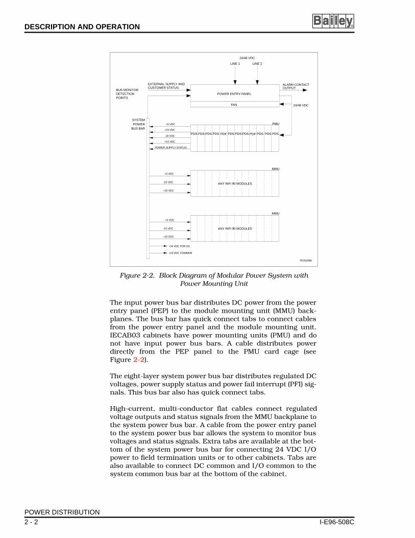
The input power bus bar distributes DC power from the powerentry panel (PEP) to the module mounting unit (MMU) back-planes. The bus bar has quick connect tabs to connect cablesfrom the power entry panel and the module mounting unit.IECAB03 cabinets have power mounting units (PMU) and donot have input power bus bars. A cable distributes powerdirectly from the PEP panel to the PMU card cage (seeFigure 2-2).
The eight-layer system power bus bar distributes regulated DCvoltages, power supply status and power fail interrupt (PFI) sig-nals. This bus bar also has quick connect tabs.
High-current, multi-conductor flat cables connect regulatedvoltage outputs and status signals from the MMU backplane tothe system power bus bar. A cable from the power entry panelto the system power bus bar allows the system to monitor busvoltages and status signals. Extra tabs are available at the bot-tom of the system power bus bar for connecting 24 VDC I/Opower to field termination units or to other cabinets. Tabs arealso available to connect DC common and I/O common to thesystem common bus bar at the bottom of the cabinet.
Figure 2-2. Block Diagram of Modular Power System with Power Mounting Unit
FAN
LINE 1 LINE 2
ALARM CONTACTOUTPUT
POWER SUPPLY STATUS
BUS MONITORDETECTIONPOINTS
EXTERNAL SUPPLY ANDCUSTOMER STATUS
+24 VDC FOR I/O
+24 VDC COMMON
+5 VDC
-15 VDC
+15 VDC
+5 VDC
+24 VDC
-15 VDC
+15 VDC
TP25245B
POWER ENTRY PANEL
PDS PDS PDS PDF PDF
24/48 VDC
24/48 VDC
+5 VDC
-15 VDC
+15 VDC
ANY INFI 90 MODULES
ANY INFI 90 MODULES
PDS PDS PDS PDS PDS PDS PDS
SYSTEMPOWER
BUS BAR
PMU
MMU
MMU
POWER DISTRIBUTION
2 - 2 I-E96-508C

DESCRIPTION AND OPERATION
I-E96-508C
POWER ENTRY PANEL
The IEPEP04 Power Entry Panel connects single or redundant24/48 VDC line power to an INFI 90 system cabinet. It also dis-tributes power to the power modules and fan assembly. Thisversion has circuit breakers for each power line input. Twomodules reside in the PEP panel. They are the DC transfermodule and bus monitor module.
DC Transfer Module
The DC transfer module monitors both power inputs and itsown circuitry. If a power input is lost or faulty, the moduleautomatically transfers to the redundant input. The DC trans-fer module generates a power fail interrupt signal if both linesare lost or below the low voltage threshold. It sends this signalto the bus monitor module. The bus monitor module sends thePFI signal to the appropriate process control modules, therebyinterrupting their operation. Visible through the front panelare three LEDs. The red and green LED at the top showswhether the module is operating normally (green) or not (red).The two other LEDs (line 1 and line 2) provide DC input status(green = good, red = bad).
Bus Monitor Module
The bus monitor module monitors the regulated bus voltages (5VDC, ±15 VDC, and 24 VDC) and power module status from thesystem power bus bar. A cable connection between the bus barand the J2 connector on the PEP panel provides the path. Thebus monitor module can also monitor two additional externalpower supply voltages at the PEP terminal blocks. User-config-ured jumpers allow the module to monitor either 24 VDC, 48VDC or 125 VDC for up to two auxiliary power supplies. Thereare two inputs for monitoring system status signals.
Jumpers are used to configure input status signals (low trueor high true). Also the status input one may be configured asan additional PFI signal (low true). Two red and green LEDs onthe module faceplate provide status information. The topmostLED shows whether the module is operating properly (green) ornot (red). The system status LED is red when voltages are lowor other inputs are bad. The status signal goes to the commu-nication system hardware, which is the bus interface modulefor plant loop systems, and the network interface slave forINFI-NET® systems. On the communication loop, any INFI 90operator interface can access the signal.
There are two alarms: PWR SYS ALARM and BUS VOLTALARM. The PWR SYS ALARM becomes active when a powersystem problem occurs. The BUS VOLT ALARM becomes active
® INFI-NET is a registered trademark of Elsag Bailey Process Automation.
POWER ENTRY PANEL
2 - 3

DESCRIPTION AND OPERATION ®
when any bus voltage (5 VDC, ±15 VDC, or 24 VDC) falls out oftolerance.
The bus monitor module also generates a power fail interruptsignal if it receives a PFI from the DC transfer module, statusinput one, or if the five VDC bus voltage is low (if selected). Itdistributes this signal to process control modules in theINFI 90 system cabinet.
FAN ASSEMBLY
The IEFAN03 and IEFAN05 Fan Assemblies contain six fansthat mount in one chassis. Its purpose is to keep the powersupplies and modules cool. The fans draw cooling air upthrough the module mounting assemblies and force it throughexhaust vents (when present) in the top of the cabinet door.
MODULE MOUNTING UNIT
The IEMMU01 and IEMMU02 Module Mounting Units providemounting for the power modules and process control modules.Two five-conductor flat cables link the power fail interrupt andpower module status signals, 5 VDC, ±15 VDC, and 24 VDC,MCOM and I/O COM from the system power bus bar to theMMU card cage. A three-wire cable from the power input busbar to the MMU backplane supplies the power modules withDC input power.
Cables are required to connect the communication busesbetween multiple MMU card cages. The module bus uses athree-wire, twisted cable, while the I/O expander bus uses aflat, 40 conductor ribbon cable.
POWER MOUNTING UNIT
The power mounting unit (IEPMU01 and IEPMU02) mountsand segregates power modules from INFI 90 process modules.Each PMU is open on the top and bottom for air flow. There are12 pairs of guides for mounting power modules, two side platesand the backplane. The backplane uses bus bars rather thantraces for heavier currents.
POWER MODULES
The DC system power modules receive input power at the MMUor PMU backplane. The IEPDS01 DC System Power Modulerequires 24 VDC input power. The IEPDS02 DC System PowerModule requires 48 VDC input power. DC-to-DC convertersconvert the primary input voltage to secondary regulated volt-ages of 5 VDC, ±15 VDC and 24 VDC. These voltages are avail-able at the system bus bar for distribution to process controlmodules. See Figures 2-3 and 2-4.
FAN ASSEMBLY
2 - 4 I-E96-508C

DESCRIPTION AND OPERATION
I-E96-508C
All output voltages are preset at the factory. In an N+1 redun-dant environment, proper operation of each module output isbased on this preset voltage. If a bus requires more current,the module automatically compensates.
NOTE: The factory preset voltages are not field-adjustable.
The IEPDF01 and IEPDF02 DC Field Power Modules are func-tionally the same as the IEPDS01 or IEPDS02 modules exceptthat they provide only 24 VDC. The DC field power module pro-vides power to field termination devices when separate termi-nation cabinets are used, or when it is desirable to separate theI/O power supplies from the module power supplies.
STATUS SIGNALS
The block diagram in Figure 2-5 shows the flow of status sig-nals through the system. The following text explains status sig-nal flow.
Power System Status
The bus monitor module logically ANDs all status lines (DCline, bus voltages, external power inputs, external user statusinputs and power module status). Internal bus monitor
Figure 2-3. Block Diagram, Power Distribution to the PDS
BMM
POWER ENTRY PANEL
MODULE MOUNTING UNITOR
POWER MOUNTING UNIT
POWER SUPPLY MODULE
DCCONV
DCCONV
DCCONV
±15 VDC
ALARMS
TP25131B
+24 VDC+5 VDC
DC OUTDC IN
SOFT START ANDHOLD UP CIRCUITRY
TO PROCESSCONTROLMODULES
STATUS OUT
PDS
FAN ASSEMBLY
DTM
STATUS SIGNALS
2 - 5

DESCRIPTION AND OPERATION ®
circuitry determines if any status line is bad. If any status isbad, the bus monitor module generates a low-true output sig-nal to the communication system hardware, which is the businterface module (BIM) for plant loop systems and the networkinterface slave (NIS) for INFI-NET systems.
Bus Voltage Status
The BMM module logically ANDs the DC bus voltage statuslines and outputs the result to an isolated customer alarm out-put. If any bus output voltage signal falls out of specification, abus voltage alarm is generated.
POWER MODULE STATUS
The power modules generate their own status signals. Thesesignals travel through the system power bus bar to the busmonitor module. The bus monitor module then combines thissignal with the other status signals. If it or any other signal isbad, a power system status alarm is generated.
Figure 2-4. Block Diagram, PDS Module Converter and Status Circuitry
DC/DC
DC/DC
DC/DC
6
7
6
7
1 2
3
4
5
6
7
I/O POWER 24 V
I/O COMMON
+5 V
SYSTEM COMMON
SYSTEM COMMON
+15 V
-15 V
STATUSALARM
DC SOFTSTARTCIRCUIT
TP25132B
5
6
7
1
2
3
4
LEGEND
+24 V OVERPOWER
+5 V SOURCE OVERPOWER
-15 V UNDER/OVERVOLTAGE
+15 V UNDER/OVERVOLTAGE
BLOWN DC INPUT FUSE
OVERTEMP SHUTDOWN
OVERVOLTAGE SHUTDOWN
POWER MODULE STATUS
2 - 6 I-E96-508C

DESCRIPTION AND OPERATION
I-E96-508C
USER ALARM OUTPUTS
There are two user alarm outputs (normally closed): bus volt-age and power system status alarm. The bus voltage alarmactivates (opens) if any bus voltage goes low or is lost. Thepower system status alarm activates (opens) for any bad sta-tus. These outputs are optically isolated and can drive relays orannunciator panels that require no more than 120 milliamps.
Figure 2-5. Status Signal Circuit Diagram
MODULE STATUS
BMM
BUSVOLT
ALARM
POWERSYS
ALARM
POWER SYSSTATUS
PFI
LIM BIM
T.U.PLANT LOOP
DC BUS
PM STAT
PFI
T.U.
NIS
INFI-NET
AUX BUS MONITOR 1
STATUS IN 2
AUX BUS MONITOR 2
MODULE STATUS (BMM)
STATUS
TP25133A
MCS, OIS, etc....
IEPEP04
DTMDC LINE 1
DC LINE 2
IEPDS01IEPDF01 IEMMU01
MODULE STATUS (DTM)
PFI
+5 V
+15 V
-15 V
+24 V
PM STAT
STATUS IN 1/PFI
USER ALARM OUTPUTS
2 - 7

SECTION 3 - INSTALLATION
I-E96-508C
INTRODUCTION
Completely install and prepare (i.e., attach wiring to terminalblocks, etc.) the hardware before applying power. This sectionexplains hardware preparation in detail.
NOTE: Normally, the cabinet is fully wired and ready to go uponreceipt. The following information is provided in the event that youneed to repair, replace, wire, or add to the modular power system.
UNPACKING AND INSPECTION
The power modules are in separate packages from the rest ofthe power system. Handle these modules per the steps in Spe-cial Handling and General Handling.
Special Handling
The power supply module, DC transfer module and bus moni-tor module use devices susceptible to electrostatic discharge.Follow these handling procedures:
NOTE: Always use Bailey Controls field static kit (part number1948385_1 - consisting of two wrist straps, ground cord assembly,alligator clip, and static dissipative work surface) when working withthe modules. The kit grounds a technician and the static dissipativework surface to the same ground point to prevent damage to themodules by electrostatic discharge.
1. Use Static Shielding Bag. Keep the modules in the staticshielding bag until you are ready to install them in the system.Save the bag for future use.
2. Ground Bag before Opening. Before opening a bag con-taining an assembly with semiconductor devices, touch it tothe equipment housing or a ground to equalize charges.
3. Avoid Touching Circuitry. Handle assemblies by theedges; avoid touching the circuitry.
4. Avoid Partial Connection of Semiconductor Device.Verify that all devices connected to the modules are properlygrounded before using them.
5. Ground Test Equipment.
6. Use an Antistatic Field Service Vacuum. Remove dustfrom the module if necessary.
INTRODUCTION
3 - 1

INSTALLATION ®
7. Use a Grounded Wrist Strap. Connect the wrist strap tothe appropriate grounding plug on the power entry panel. Thegrounding plug on the power entry panel must be effectivelyconnected to the earth grounding electrode system throughthe AC safety ground.
8. Do Not Use Lead Pencils to Set Dipswitches. To avoidcontamination of dipswitch contacts that can result in unnec-essary circuit board malfunction, do not use a lead pencil toset a dipswitch.
General Handling
1. Examine the hardware immediately to verify that it has notbeen damaged in transit.
2. Notify the nearest Bailey Controls sales office of any suchdamage.
3. File a claim for any damage with the transportation com-pany that handled the shipment.
4. Use the original packing material and container to storethe hardware.
5. Store the hardware in an environment of good air quality,free from temperature and moisture extremes.
SYSTEM INSTALLATION
The following factors should be considered when determiningthe installation location of the system cabinet:
• The humidity of the location must not go above 95 percentnoncondensing at 55 degrees Celsius (131 degrees Fahren-heit).
• The floor of the location must be able to bear a load of362.9 kilograms (800 pounds).
• There should be a 914.4-millimeter (three-feet) clearanceboth front and back for opening cabinet doors.
• A power source for 24 VDC, 60 amp service or 48 VDC, 30amp service must be available for fully loaded cabinets ( nomore than eight modular power supplies). Power sourcesfor 24 VDC systems that supply cabinets having less thaneight power modules should have a service that can supply7.6 amps per module. Power sources for 48 VDC systemsthat supply less than fully loaded cabinets, should have aservice that can supply 3.8 amps per power module.
Refer to the Site Planning and Preparation instruction foradditional information. The standard cabinet configuration is
SYSTEM INSTALLATION
3 - 2 I-E96-508C

INSTALLATION
I-E96-508C
the power entry panel at the top, with the fan assembly placedbetween the power entry panel and the module mountingunits. See Figure 3-1.
IEPEP04 POWER ENTRY PANEL WIRING
The appendices at the back of this manual show complete wir-ing diagrams of the modular power system. Figures C-1 andC-2 show the IEPEP04 system cabinet wiring diagram.
NOTE: Plug your wrist strap ground cord into the WRIST STRAPGND receptacle on the power entry panel when working with thesystem.
Figure 3-1. System Cabinet (Rear View)
1 2 3 4 5 6 7 8
1 2 3 4
I/O COM+24 VPM STAT
+15 V-15 V
PFI
MCOM
J2
+ - + -
AUX BUSMONITOR
CH 1 CH 2
+ - + -
BUS VOLTPWR SYSALARMS
STATUSOUT
STATUS IN
1 MCOM 2
FAN ASSEMBLY
GND
FAN OUT
DCTRANSFER
BUSMONITOR
TB9TB8 TB10 TB11 TB12
OUT OUT
L1 IN L2 IN
TB3 TB4 TB5 TB6 TB7
INPUT POWERBUS BARSYSTEM POWER
BUS BAR
TB1
TP25145A
POWER ENTRY PANELIEPEP04
TB2
24/48 VDC (+)
LINE 1 (-) LINE 2 (-)
24/48 VDC (+)
+
+ +
+-
- -
-
IEPEP04 POWER ENTRY PANEL WIRING
3 - 3
INSTALLATION ®
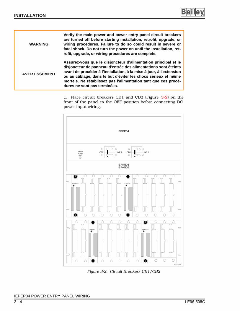
1. Place circuit breakers CB1 and CB2 (Figure 3-2) on thefront of the panel to the OFF position before connecting DCpower input wiring.
WARNING
Verify the main power and power entry panel circuit breakersare turned off before starting installation, retrofit, upgrade, orwiring procedures. Failure to do so could result in severe orfatal shock. Do not turn the power on until the installation, ret-rofit, upgrade, or wiring procedures are complete.
AVERTISSEMENT
Assurez-vous que le disjoncteur d'alimentation principal et ledisjoncteur de panneau d'entrée des alimentations sont éteintsavant de procéder à l'installation, à la mise à jour, à l'extensionou au câblage, dans le but d'éviter les chocs sérieux et mêmemortels. Ne rétablissez pas l'alimentation tant que ces procé-dures ne sont pas terminées.
Figure 3-2. Circuit Breakers CB1/CB2
CB1CB2 LINE 2 LINE 1
TP25137A
WRISTSTRAPGND
IEPEP04
IEFAN03IEFAN05
IEPDS0IEPDS0
IEPDS0IEPDS0
IEPEP04 POWER ENTRY PANEL WIRING
3 - 4 I-E96-508C

INSTALLATION
I-E96-508C
2. Connect 24 VDC or 48 VDC primary (L1) input power toTB3 (+), TB4 (-) and TB5 (GND) (Figure C-1).
3. Connect the secondary (L2) DC power input (if used) toTB5 (GND), TB6 (-) and TB7 (+). Both inputs must be the samenominal voltage level. If only 1 DC power input is being used,proceed with Step 4. If not, skip to Step 5.
4. Connect TB3 to TB7 and TB4 to TB6. Use 6 AWG wire.Note that this step avoids false status information because itconnects line 1 and line 2 inputs together.
5. Connect cable 6637813_1 from J2 on the power entrypanel to the system power bus bar. This provides connectionsto sample the DC output bus voltages, monitor the power mod-ule status signal and to output a power fail interrupt signal.See the wiring diagrams at the end of this manual (Figure C-1)for correct system power bus bar connections.
6. Connect cable 6639443_1 from TB8, TB9, TB10, TB11 andTB12 on the panel to the input power bus bar for distributionof DC power to the module mounting unit (Figure C-1).
7. Connect cable 6637818_2 from the input power bus bar toeach module mounting unit backplane (Figure C-1).
8. Connect the fan assembly power cable to connector J1labeled FAN OUT on the panel (Figure C-1).
9. Connect a wire equivalent to power wiring but not lessthan 6 AWG from the TB10 (GND) stud of the panel to the cab-inet frame for DC input safety grounding (Figure C-1).
10. There are 2 extra voltage monitor inputs available to moni-tor customer external power supply voltages (see Figure C-1).Use terminal block TB2 labeled AUX BUS MONITOR for thispurpose. Attach one input to terminals 1(+) and 2(-) labeledCH1. Connect the other input to terminals 3(+) and 4(-) labeledCH2. Inputs can be 24 VDC, 48 VDC or 125 VDC. Set jumpersJ1 and J2 for the desired voltage. Refer to Table 3-2.
11. Wire the status inputs to terminal block TB1, terminals 1(STATUS IN 1), 2 (COM) and 3 (STATUS IN 2). Insure that theinputs are open collector or contact type referenced to DCcommon (terminal COM). The alarm inputs must have the cur-rent carrying capability to sink at least 1 mA. If the systemuses Plant Loop, do Step 12. If not, go to Step 13.
12. Connect cable 6634205_1 from TB1 terminal 4 STATUSOUT to the P3 card edge connector of the bus interface module(BIM). Doing so enables the BIM to send the status message to
IEPEP04 POWER ENTRY PANEL WIRING
3 - 5

INSTALLATION ®
the loop interface module (LIM) and to the Plant Loop. Ifredundant BIMs are used, connect cable 6634205_1 from eachBIM to TB1 terminal 4 STATUS OUT. Go to Step 16.
13. Connect an 18 AWG wire from TB1 terminal 4 STATUSOUT to TB1 terminal 8 on the NTCL01 termination unit.
14. If redundant network interface slave modules are beingused with the NTCL01 termination unit:
a. Put two 18 AWG wires on a lug. Attach the lug to TB1terminal 4 STATUS OUT.
b. Attach the primary wire to TB1 terminal 8; the second-ary to TB3 terminal 8.
15. If redundant network interface slave modules are beingused with the NICL01 termination module:
a. Put two 18 AWG wires on a lug. Attach the lug to TB1terminal 4 STATUS OUT.
b. Attach the primary wire to TB2 terminal 4; the second-ary to TB2 terminal 5.
16. Use 18 AWG wire if connecting TB1 terminals 5, 6, 7 and 8to alarms. Terminals 5(+) and 6(-) are labeled PWR SYS. Theseare the output connections for the power system alarm. Termi-nals 7(+) and 8(-) labeled BUS VOLT are the bus voltage alarmannunciators.
NOTE: Wire your system per the color codes in the wiring diagramsof Appendix C.
DC Transfer Module
Before installing the DC transfer module, set jumper J13 for24 VDC or 48 VDC operation. Refer to Table 3-1 for jumperassignments. Figure 3-3 shows the DC transfer module boardlayout. Set jumpers J1 through J4 for the desired overvoltageor undervoltage detection (see Table 3-1).
NOTE: Both the DC transfer and bus monitor modules mount fromthe rear of the system cabinet. The DC transfer module mounts inthe leftmost slot; the bus monitor module mounts in the rightmostslot. The board edge connectors are keyed to prevent mounting inthe wrong slots.
To mount the module:
1. Grasp the sides of the faceplate.
2. Line up the circuit board edges with the card guides in itspower entry panel mounting slot (see Figure 3-2).
IEPEP04 POWER ENTRY PANEL WIRING
3 - 6 I-E96-508C

INSTALLATION
I-E96-508C
3. Slide the module into the slot until its faceplate is flushwith the power entry panel.
4. Turn the 2 thumbscrews 1/2-turn to lock the module inplace.
Bus Monitor Module
Before mounting the bus monitor module, set jumpers J1through J7. Refer to Table 3-2 for switch settings. Refer to
Figure 3-3. DC Transfer Module Board Layout
TP25141A
J13
1 2 3
125V
48V
24V125V
48V
24V
J1
J2
J3
J4
CR1
CR2
CR3
RED/GREENSTATUS
LINE 1
LINE 23412
3412
3412
3412
Table 3-1. DC Transfer Module Jumper Settings
Jumper Setting Function
J11-42-4
Line 1 input:24 VDC high detect48 VDC high detect
J21-42-4
Line 1 input:24 VDC low detect48 VDC low detect
J31-42-4
Line 2 input:24 VDC high detect48 VDC high detect
J41-42-4
Line 2 input:24 VDC low detect48 VDC low detect
J132-31-2
Input power source:24 VDC48 VDC
NOTE: Short pins with a jumper to enable function.
IEPEP04 POWER ENTRY PANEL WIRING
3 - 7

INSTALLATION ®
Table 3-3 for jumper definitions. See Figure 3-4 for the busmonitor module circuit board layout.
Table 3-2. Bus Monitor Module Switch (S1) Setting
PoleFunction
1 2 3 4
01
Monitor 5, 15 and ±15 VDC enabledMonitor 5, 15 and ±15 VDC disabled
01
Monitor system 24 VDC enabledMonitor system 24 VDC disabled
01
Monitor external power supply CH1 enabledMonitor external power supply CH1 disabled
01
Monitor external power supply CH2 enabledMonitor external power supply CH2 disabled
NOTE: 0 = CLOSED (ON), 1 = OPEN (OFF).1. Unused monitor inputs must be disabled. Do not enable all switches at once. Doing so will causea bad status signal. Figure 3-4 shows the factory settings of switch S1.
Table 3-3. Bus Monitor Module Jumper Settings
Jumper Setting 1 Function
J11-22-42-3
Auxiliary bus monitor channel 1:Selects 24 VDC external powerSelects 48 VDC external powerSelects 125 VDC external power
J21-22-42-3
Auxiliary bus monitor channel 2:Selects 24 VDC external powerSelects 48 VDC external powerSelects 125 VDC external power
J3 2-3 Not used, must install jumper in this position
J41-22-33-4
Auxiliary status input 1:Normally open (NO) status inputNormally closed (NC) status inputPFI input (NO)
J51-22-3
Auxiliary status input 2:Normally open (NO) status inputNormally closed (NC) status input
J62
1-22-3
Input power isolation:Do not isolate input powerIsolate input power
J7 2-3 Not used, must install jumper in this position
J82
1-22-3
Input/output common isolation:Isolate input common from output commonDo not isolate input common from output common
NOTES:1. Short pins with a jumper to enable function.
2. Jumpers J8 and J6 must be set so that they correspond (i.e.,both set for isolation or no isolation).
IEPEP04 POWER ENTRY PANEL WIRING
3 - 8 I-E96-508C

INSTALLATION
I-E96-508C
Fan Assembly
The fan assembly (Figure 3-1) mounts directly beneath thepower entry panel and above the first module mounting unit.Attach the fan power cable to the FANOUT connector on thepower entry panel.
Power Modules
Power modules (Figure 3-5) mount directly in the modulemounting unit (MMU). Any slot except the rightmost (slot 12)can be used. Install the modules as explained in Steps 1through 5 and as shown in Figure 3-6. This installationscheme provides the best heat dissipation and power distribu-
Figure 3-4. Bus Monitor Module Board Layout
S1
J1
P3
TP50301B
CR12
CR17
ON
1 2 3 4
J2
J3
J4
J5
J6
J7
1
2
3
4
1 2 3
4
1 2 3
J8
1 2 3
1
2
3
1
2
3
1
2
3
4
1
2
3
Figure 3-5. Power Module Board Layout
ABJ3
CR9
F1
ABJ2
TP25136B
AB
J3 POSITION A - FOR +5, +24, +15, -15 V MONITORINGJ3 POSITION B - TO DISABLE ±15 VDC MONITORING
AB
J2 POSITION B FOR IEPDF0J2 POSITION A FOR IEPDS0
IEPEP04 POWER ENTRY PANEL WIRING
3 - 9

INSTALLATION ®
tion. For optimum heat dissipation and power distribution, donot exceed more than two IEPDS01 and IEPDS02 modules inany module mounting unit. Install at least one IEPDS01 andIEPDS02 module in the module mounting unit with the largestload (i.e., an MMU card cage containing several multi-functionprocessor modules).
NOTE: The power mounting unit can hold a maximum of 12 powermodules mounted side by side. However the total five VDC currentload on the power mounting unit cannot exceed 100 amps. The total24 VDC current load on the power mounting unit cannot exceed 60amps.
Before handling the power modules:
• Verify that all devices connected to the module are properlygrounded before using them.
Figure 3-6. Recommended Power Module Layout
TP25135A
PDS PDS
1 2 3 4 5 6 7 8 9 10 11 12
PDSPDS
PDS PDS
PDSPDS
NOTUSED
NOTUSED
NOTUSED
NOTUSED
WARNINGDo not remove the plastic covers on the module mounting unitbackplane. These covers protect against accidental contactwith DC voltage. Severe or fatal shock could result.
AVERTISSEMENT
Ne retirez pas les couvercles de plastique situés sur le pan-neau arrière du châssis de montage des modules. Ces couver-cles constituent une protection contre les contacts accidentelsavec la tension c.c., qui risquent de provoquer des chocssérieux et même mortels.
IEPEP04 POWER ENTRY PANEL WIRING
3 - 10 I-E96-508C

INSTALLATION
I-E96-508C
• Avoid touching the circuitry when handling the module.
• Always use grounding straps (field static kits) when work-ing with the modules.
To install the power modules:
1. Refer to Figure 3-5 to set jumper J2 for module type andJ3 for bus voltage monitoring.
2. Grasp the module faceplate handle and align the top andbottom edges of the circuit board with the guides in the mod-ule mounting unit or power mounting unit.
3. Hold the module by the faceplate handle and slide it intoits mounting slot. Push on the module faceplate until the rearedge connector is firmly seated in the backplane connector.
4. Firmly push on the module handle as you use a bladescrewdriver to push and turn the 2 latching screws 1/2-turnclockwise to lock the module in place.
To remove the module, refer to POWER MODULE REPLACE-MENT in Section 7 of this manual.
IEPMU01/02 POWER MOUNTING UNIT INSTALLATION
Required Tools
You will need these tools to install the power mounting unit:
• 16-inch flat screwdriver.• 7/16-inch nut driver.• Pliers.• Volt/ohmmeter.• Heat gun.
WARNING
Verify the main power and power entry panel circuit breakersare turned off before starting installation, retrofit, upgrade, orwiring procedures. Failure to do so could result in severe orfatal shock. Do not turn the power on until the installation, ret-rofit, upgrade, or wiring procedures are complete.
AVERTISSEMENT
Assurez-vous que le disjoncteur d'alimentation principal et ledisjoncteur de panneau d'entrée des alimentations sont éteintsavant de procéder à l'installation, à la mise à jour, à l'extensionou au câblage, dans le but d'éviter les chocs sérieux et mêmemortels. Ne rétablissez pas l'alimentation tant que ces procé-dures ne sont pas terminées.
IEPMU01/02 POWER MOUNTING UNIT INSTALLATION
3 - 11
INSTALLATION ®
Installing the PMU in the INFI 90 Cabinet
NOTE: Install the IEPMU01 mounting unit from the rear of the cabi-net, the IEPMU02 mounting unit from the front.
1. Mount the power mounting unit directly beneath the fanassembly.
2. Secure both sides of the power mounting unit to the cabi-net mounting rails.
3. Proceed to Wiring Instructions.
Wiring Instructions
NOTE: All wiring is done in the rear of the cabinet. Wires arecolor-coded. This procedure and Figure C-2 apply to INFI 90 cabi-nets only.
1. Attach the DC input wire harness (part number6639443_2) to TB8, TB9, TB10, TB11 and TB12 on the powerentry panel (PEP) (see Figure C-2 for wire assignments) to the 2DC input terminals on the right side of the PMU as follows:
Black to top conductive strip on right hand side of PMU(DC Com).
Red to second conductive strip on right hand side of PMU(24/48 V).
Green/yellow to top screw of terminal block P3 (ground) onright hand side of PMU.
2. Before installing the 0 AWG (part number 206632285_45 or6632285_47) braided wire, shape it into a [ form to avoid over-stressing the PMU bus bar terminals. On the left side of thePMU at the third conductive strip (from the top), attach one endof the first 0 AWG wire assembly (part number 6632285_47).
3. Attach the other end to the MCOM tab at the top of thesystem power bus bar. See Figure C-2.
4. Slide heat shrink tubing over PMU connection. See Figure3-7. Insure that connections are properly covered, then useheat gun to shrink the tubing into place.
5. On the left side of the PMU at the fourth conductive strip(from the top), attach one end of the second 0 AWG wireassembly (part number 6632285_45).
6. Attach the other end to the 5 VDC tab at the top of the sys-tem power bus bar. See Figure C-2.
IEPMU01/02 POWER MOUNTING UNIT INSTALLATION
3 - 12 I-E96-508C

INSTALLATION
I-E96-508C
7. Slide heat shrink tubing over PMU connection (see Figure3-7). Insure that connections are properly covered, then useheat gun to shrink the tubing into place.
8. Attach one end of the 6 AWG wire assembly (part number6632885_48) to the fifth conductive strip (from the top) on theleft side of the PMU.
9. Attach the other end of 6 AWG wire assembly to the systempower bus bar I/O COM tab located at the top of the bus bar.
10. Slide heat shrink tubing over PMU connection (seeFigure 3-8). Insure that connections are properly covered, thenuse heat gun to shrink the tubing into place.
11. On the left side of the PMU at the sixth conductive strip(from the top) attach one end of 6 AWG wire assembly (partnumber 6632885_48).
12. Attach the other end of 6 AWG wire assembly to systempower bus bar 24 VDC tab located at the top of the bus bar.
13. Slide heat shrink tubing over PMU connection (see Figure3-8). Insure that connections are properly covered, then useheat gun to shrink the tubing into place.
NOTE: If system bus bar (Bailey part number 1948506_8) is revi-sion C or older, it will not have tabs at the top for 24 VDC connec-tions. Use the 10 AWG wires supplied with the PMU to connect tothe system power bus bar fastons identified as 24 V and I/O COM.
Figure 3-7. Heat Shrink Tubing for 5 VDC Connection
6632285 47� MCOM
6632285 45�
HEAT SHRINKTUBING
PMUBUS BAR
STANDOFF
+5 V
NOTE: AFTER JUMPER CONNECTION IS MADE, SLIDE HEAT SHRINKTUBING SUPPLIED WITH P/N 6632285 45 AND 6632285 47 OVERCONNECTION UNTIL CONNECTION IS COVERED COMPLETELY ANDSHRINK INTO PLACE WITH HEAT GUN.
� �
TP50376B
IEPMU01/02 POWER MOUNTING UNIT INSTALLATION
3 - 13

INSTALLATION ®
14. Attach one spade lug end of 10 AWG wire assembly (partnumber 206632285_46) to PMU +15 VDC. Attach the otherspade lug end to system power bus bar +15 VDC.
15. Attach one spade lug end of 10 AWG wire assembly (partnumber 206632285_46) to PMU -15 VDC. Attach the otherspade lug end to system power bus bar -15 VDC.
16. Attach one spade lug end of 18 AWG wire assembly (partnumber 20663228_49) to PMU STATUS. Attach the otherspade lug end to system power bus bar status.
17. Attach spade lugs of cable assembly (part number6637813_1) for signal connections from IEPEP04 connector J2to the system power bus bar appropriately.
18. Verify that the circuit breakers on the PEP are in the OFFposition.
19. Unplug all process and slave modules from the MMU back-plane.
20. Verify that all wiring connections are complete before turn-ing on the source power.
21. Use a voltmeter to measure 24 VDC or 48 VDC power atTB3 and TB7.
Figure 3-8. Heat Shrink Tubing for 24 VDC Connection
6632285 48� I/O COM
6632285 48�
HEAT SHRINKTUBING
PMUBUS BAR
STANDOFF
+24 V
NOTE: AFTER JUMPER CONNECTION IS MADE, SLIDE HEAT SHRINKTUBING SUPPLIED WITH P/N 6632285 48 OVER CONNECTIONUNTIL CONNECTION IS COVERED COMPLETELY AND SHRINK INTOPLACE WITH HEAT GUN.
�
TP50375B
IEPMU01/02 POWER MOUNTING UNIT INSTALLATION
3 - 14 I-E96-508C

INSTALLATION
I-E96-508C
22. Turn PEP circuit breakers on.
NOTE: Before doing step 23, verify that switch and jumper settingson the power modules are correct. Refer to Section 3 for settings.
23. Install the required number (calculated from SIZING THEMODULAR POWER SYSTEM in Appendix B) of PDS (or PDF)modules in the PMU one at a time. Slide 1 power module alongthe guides until it is seated. Turn the 2 latching screws untilthey lock. Verify that the status LED turns green on eachpower module. If it does not, refer to Section 5.
24. Do not install the process modules at this time. Refer toRECOMMENDED START-UP PROCEDURES in Section 4,Steps 5 through 8.
IEPMU01/02 POWER MOUNTING UNIT INSTALLATION
3 - 15
SECTION 4 - OPERATING PROCEDURES
I-E96-508C
INTRODUCTION
This section covers what must be known to operate the modu-lar power system. The first part of this section provides astep-by-step approach to start-up. The remainder of this sec-tion explains the faceplate LED on the DC transfer, bus moni-tor and power modules, and other general operatinginformation.
NOTE: The modular power system requires no user calibration; allcomponents are factory calibrated.
LED INDICATORS
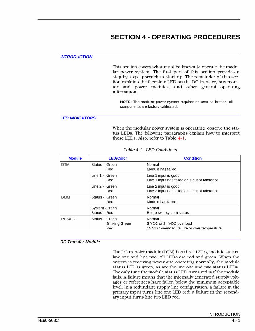
When the modular power system is operating, observe the sta-tus LEDs. The following paragraphs explain how to interpretthese LEDs. Also, refer to Table 4-1.
DC Transfer Module
The DC transfer module (DTM) has three LEDs, module status,line one and line two. All LEDs are red and green. When thesystem is receiving power and operating normally, the modulestatus LED is green, as are the line one and two status LEDs.The only time the module status LED turns red is if the modulefails. A failure means that the internally generated supply volt-ages or references have fallen below the minimum acceptablelevel. In a redundant supply line configuration, a failure in theprimary input turns line one LED red; a failure in the second-ary input turns line two LED red.
Table 4-1. LED Conditions
Module LED/Color Condition
DTM Status - Green Red
NormalModule has failed
Line 1 - Green Red
Line 1 input is good Line 1 input has failed or is out of tolerance
Line 2 - Green Red
Line 2 input is goodLine 2 input has failed or is out of tolerance
BMM Status - Green Red
NormalModule has failed
System -Green Status - Red
Normal Bad power system status
PDS/PDF Status - GreenBlinking GreenRed
Normal5 VDC or 24 VDC overload 15 VDC overload, failure or over temperature
INTRODUCTION
4 - 1

OPERATING PROCEDURES ®
Bus Monitor Module
The bus monitor module (BMM) has two LEDs: module statusand system status. The module status LED is green when themodule is operating properly. It turns red if the module fails. Afailure means that the internally generated supply voltages orreferences have fallen below the minimum acceptable level.The system status LED is green when everything in the systemis satisfactory. If for some reason a bus voltage fails or falls outof tolerance, one of the DC inputs fails, external status, auxil-iary power supply inputs are low, or the DTM module fails, theLED turns red.
Power Module
The power module has one LED, module status. This LED isgreen when the module is operating normally. It blinks green ifthe five VDC or 24 VDC circuits overload. It turns red if the 15VDC circuits overload, if one or more outputs fail, or if moduletemperature goes beyond acceptable levels.
DC TRANSFER MODULE/BUS MONITOR MODULE REMOVAL DURING OPERATION
The DC transfer module and bus monitor module can beremoved while the system is in operation.
NOTE: If power from the operational line is lost and the DTM mod-ule is out of the system the entire power system will go down. Like-wise, the power system status is not available to the user while theBMM module is out of the system.
RECOMMENDED START-UP PROCEDURES
Follow this procedure to apply power to the system.
1. Verify that all connections are secure.
2. Insure that all unused DC bus bar receptacles are coveredwith insulated receptacles.
3. Install the power modules only (refer Section 3 for details).
4. Turn power on.
5. Measure the bus voltages at the test jacks of the bus moni-tor module (5 VDC and ±15 VDC are with respect to MODCOM; 24 VDC with respect to I/O COM). Refer to Table 4-2 forthe unloaded DC bus voltage requirements.
6. When the bus voltages are at acceptable levels, start addingprocess control modules.
DC TRANSFER MODULE/BUS MONITOR MODULE REMOVAL DURING OPERATION
4 - 2 I-E96-508C

OPERATING PROCEDURES
I-E96-508C
7. Continue adding process control modules until the systemcabinet is filled.
8. Measure the voltages when the system cabinet is filled andverify that they are within the acceptable levels in Step 5. Referto Table 1-4 for power module outputs under load.
NOTE: A red status light at this point may indicate an overload con-dition or defective module. If this happens, replace the suspectpower module. If the condition still exists, add power modules tomeet the system current requirements. Use the procedures inAppendix B to size the power system.
9. For optimum cooling, put blank faceplate (Bailey Controlspart number 6636586_1) in any unused slots.
Table 4-2. Typical Unloaded DC Bus Output Voltage Requirements
5 VDC 24 VDC +15 VDC -15 VDC
Min Max Min Max Min Max Min Max
5.1 5.25 25.5 27 15 15.75 -15 -15.75
RECOMMENDED START-UP PROCEDURES
4 - 3

SECTION 5 - TROUBLESHOOTING
I-E96-508C
INTRODUCTION
The flowchart in Figure 5-1 represents basic troubleshootingprocedures. They are not intended to be all encompassing. Forstep-by-step details, refer to the supportive text.
TROUBLESHOOTING DC MODULAR POWER SYSTEMS
Most power system problems cause a bad status flag at theoperator interface. This appears as an S on the system statusdisplay of an operator interface station or management com-mand system. Additionally, LED indicators on the bus monitorand DC transfer modules become red. The LED on the powersupply module will blink green when the five VDC or 24 VDCcircuits overload. It turns red if the 15 VDC circuits overload, ifone or more outputs fail, or if module temperature goes beyondacceptable levels. Additionally, user alarm outputs are acti-vated if a low bus voltage or other power system problemoccurs.
Follow the steps below if bad status is detected:
1. Check the LED indicators on the DC transfer and bus mon-itor modules.
2. If the DC transfer module status LED is red, the modulehas failed and must be replaced. A defective DC transfer mod-ule may cause the bus monitor module to show bad status.
NOTE: Refer to Section 7 for details on module removal andreplacement.
3. If the bus monitor module status LED is red, the modulehas failed and must be replaced.
4. If both module LEDs are green, check the line 1 and line 2LEDs on the DC transfer module.
5. If either of these LEDs is red, this means a loss of DC inputpower, or bad quality.
6. Verify that the circuit breakers are in the ON position.
7. If circuit breakers are on and the line LEDs are still red, thepower entry panel has failed. Replace the power entry panel.
8. If all DC transfer module LEDs are green, look at the busmonitor module LEDs.
INTRODUCTION
5 - 1

TROUBLESHOOTING ®
9. If bus monitor module status LED is red, the module hasfailed and must be replaced. If it is green, proceed.
10. If the system status LED is red, measure the bus voltagesat the test jacks (on the module front panel).
11. If the measurements made in Step 10 are good, look at thepower supply module status LEDs. If one or more are blinkinggreen or red, an overload condition may exist.
12. Install additional power supply modules.
13. Check power supply modules that had blinking green orred LEDs. If they are still blinking green or red, they havefailed. Install a good power module, then remove the faultymodule.
14. If the system status LED is red, bus voltages are good andthere are no red or blinking green LEDs on the power supplymodules, the problem is in the external inputs being monitoredby the bus monitor module.
15. If user external power supply voltages are being monitoredat the AUX bus monitor inputs to the power entry panel, verifythe jumper settings on the bus monitor module are correctlyset for the voltage levels being monitored (refer to Table 3-3 forjumper settings).
16. If switch settings are okay, measure the voltages betweenTB2-1 and TB2-2 or TB2-3 and TB2-4 on the power entrypanel. Voltages should be:
Greater than 22.2 VDC if set for 24 VDC
Greater than 44.2 VDC if set for 48 VDC
If the voltages are correct, there is a problem in one of the aux-iliary status inputs (STATUS IN) at terminal block TB1 on thepower entry panel.
17. Measure the voltage from terminal 1 and terminal 3 withrespect to terminal 2 of TB1. The voltage measured at theseterminals will depend on how J4 and J5 are set on the busmonitor module. If J4 and J5 are set for normally open (NO)status input and the voltage measures greater than 0.7 VDC,the input status is bad. If J4 and J5 are set for normally closed(NC) status input and the voltage measures less than 3.5 VDC,the input status is bad. To verify the external device causingthe bad status, remove the suspect input wire. The SYSTEMSTATUS LED should turn green if the external device was pull-ing the input low or high.
TROUBLESHOOTING DC MODULAR POWER SYSTEMS
5 - 2 I-E96-508C
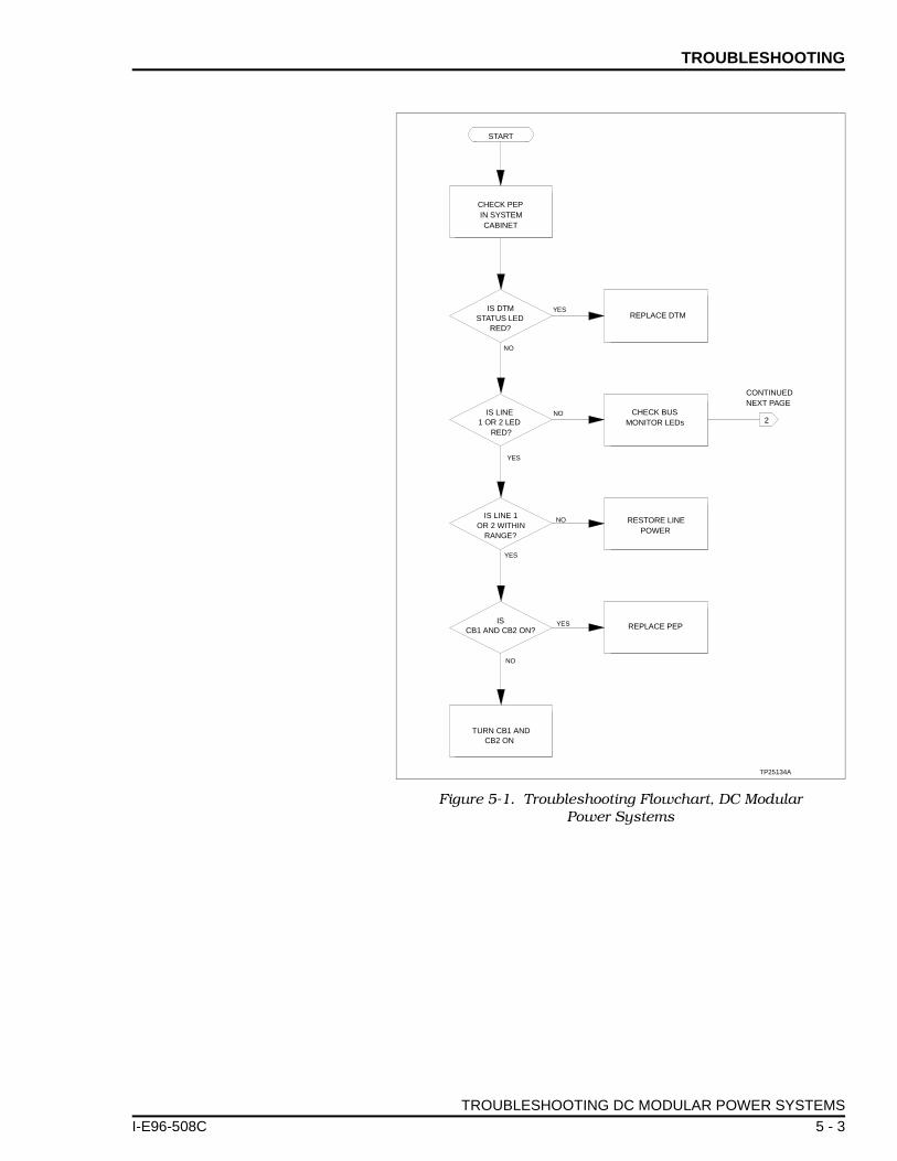
TROUBLESHOOTING
I-E96-508C
Figure 5-1. Troubleshooting Flowchart, DC Modular Power Systems
START
YES
CHECK PEPIN SYSTEMCABINET
YES
NO
NO CHECK BUSMONITOR LEDs
YES
NO RESTORE LINEPOWER
CONTINUEDNEXT PAGE
2
YES
NO
REPLACE PEP
IS DTMSTATUS LED
RED?
REPLACE DTM
TP25134A
IS LINE 1OR 2 WITHIN
RANGE?
IS LINE1 OR 2 LED
RED?
ISCB1 AND CB2 ON?
TURN CB1 ANDCB2 ON
TROUBLESHOOTING DC MODULAR POWER SYSTEMS
5 - 3

TROUBLESHOOTING ®
Figure 5-1. Troubleshooting Flowchart, DC Modular Power Systems (continued)
YES
NO
NO
2
ISBMM STATUS LED
RED?
REPLACE BMM.REFER TO REPAIR/
REPLACEMENTPROCEDURES
YES
NOIS
SYSTEM STATUSLED RED?
AREOUTPUT VOLTAGES
GOOD?
TP55172C
IS SYSTEMSTATUS LED
GREEN?
NO
YES
ADD POWERMODULES.REFER TO
INSTALLATION
CONTINUED FROMPREVIOUS PAGE
YES
YESMORE CABINETCOOLING
REQUIRED
NO
YESIS
POWERMODULE BLINKING
RED?
NO
3
POWERMODULE LED
BLINKING RED &GREEN?
CONTINUEDNEXT PAGE
DONE
YES
ISPOWER
MODULE STATUSLED RED?
REPLACEPOWER MODULE.
REFER TO REPAIR/REPLACEMENTPROCEDURES
NO
YES
ISPOWER MODULE
LED BLINKINGGREEN?
ADD POWERMODULES.REFER TO
INSTALLATION
DONE
4
CONTINUEDFROM
NEXT PAGE
NO
5
CONTINUEDFROM
NEXT PAGE
TROUBLESHOOTING DC MODULAR POWER SYSTEMS
5 - 4 I-E96-508C
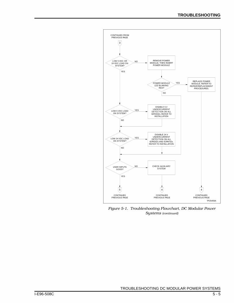
TROUBLESHOOTING
I-E96-508C
Figure 5-1. Troubleshooting Flowchart, DC Modular Power Systems (continued)
CONTINUED FROMPREVIOUS PAGE
CONTINUEDPREVIOUS PAGE
CONTINUEDPREVIOUS PAGE
CONTINUEDPREVIOUS PAGE
TP25406A
LOW 5 VDC OR24 VDC LOAD ON
SYSTEM?
LOW 5 VDC LOADON SYSTEM?
LOW 24 VDC LOADON SYSTEM?
USER INPUTSGOOD?
POWER MODULELED BLINKING
RED?
REMOVE POWERMODULE, THEN INSERT
POWER MODULE
REPLACE POWERMODULE. REFER TO
REPAIR/REPLACEMENTPROCEDURES.
DISABLE 5 VUNDERCURRENT
DETECTION ON ALLIEPAS02s. REFER TO
INSTALLATION
DISABLE 24 VUNDERCURRENT
DETECTION ON ALLIEPAS02s AND IEPAF02s.REFER TO INSTALLATION
CHECK AUXILIARYSYSTEM
NO
YES
YES
NO
NO
YES
NO
NO
YES
YES
3
5 4 4
TROUBLESHOOTING DC MODULAR POWER SYSTEMS
5 - 5

SECTION 6 - MAINTENANCE
I-E96-508C
INTRODUCTION
This section contains a modular power system preventivemaintenance schedule and procedures. Doing the preventivemaintenance procedures as scheduled maintains good,dependable modular power system operation.
WARNINGThere are exposed DC connections inside the cabinet. Theseexposed electrical connections present a shock hazard thatcan cause injury or death.
AVERTISSEMENTCette armoire comporte des connexions c.c. dénudées. Cesconnexions électriques présentent un danger d'électrocutionpouvant entraîner des blessures ou la mort.
WARNINGNever clean electrical parts or components with the power on.Doing so exposes you to a fatal electrical shock hazard.
AVERTISSEMENTIl ne faut jamais nettoyer des pièces ou des composants élec-triques lorsqu'ils sont sous tension. Ceci présente un risqued'électrocution fatale.
WARNING
If input or output circuits are a shock hazard after disconnect-ing system power at the power entry panel, then the door of thecabinet containing these externally powered circuits must bemarked with a warning stating that multiple power sourcesexist.
AVERTISSEMENT
Si des circuits d'entrée ou de sortie sont alimentés à partir desources externes, ils présentent un risque de choc électriquemême lorsque l'alimentation du système est débranchée dupanneau d'entrée l'alimentation. Le cas échéant, un avertisse-ment signalant la présence de sources d'alimentation multiplesdoit être apposé sur la porte de l'armoire.
WARNING
Wear eye protection whenever working with cleaning solvents.When removing solvents from printed circuit boards usingcompressed air, injury to the eyes could result from splashingsolvent as it is blown off the printed circuit board.
AVERTISSEMENT
Portez toujours des lunettes de protection lorsque vous uti-lisez des solvants de nettoyage. L'air comprimé servant àenlever le solvant des cartes de circuits imprimés provoquedes élaboussures qui risquent d'atteindre les yeux.
INTRODUCTION
6 - 1

MAINTENANCE ®
This section presents procedures that the customer should beable to perform on site. These preventive maintenance proce-dures should be used as a guideline to assist in establishinggood preventive maintenance practices. Select the minimumsteps required to meet the cleaning needs of your system.
Personnel performing preventive maintenance should meet thefollowing qualifications.
• Maintenance personnel should be qualified electrical tech-nicians or engineers that know the proper use of test equip-ment such as digital multimeters.
• Maintenance personnel should be familiar with the INFI 90modular power system, have experience working with pro-cess control systems, and know what precautions to takewhen working on live DC systems.
PREVENTIVE MAINTENANCE SCHEDULE
Table 6-1 is the preventive maintenance schedule and checklist for the modular power system. The table lists the preven-tive maintenance tasks in groups according to their specifiedmaintenance interval. Some tasks in Table 6-1 are self explan-atory. Instructions for tasks that require further explanationare covered under PREVENTIVE MAINTENANCE PROCE-DURES.
NOTE: The preventive maintenance schedule list is for general pur-poses only. Your application may require special attention.
Table 6-1. Preventive Maintenance Schedule
Preventive Maintenance Task Frequency
Check the cabinet air filters. Clean or replace them as necessary. Check the air filter more frequently in excessively dirty environments. Refer to procedure.
3 months
Check cabinet for dust. Clean as necessary using an antistatic vacuum.
Check all signal, power and ground connections within the cabinet and verify that they are secure. Refer to procedure.
Check modular power supply outputs. Refer to procedure. 6 months
Do a visual inspection of the fan assembly. Verify that all fans are rotating and replace if necessary.
Check the quality of the plant power and grounding system. Follow the power and grounding system verification procedures in the INFI 90 site preparation and planning instruction.
12 months
Inspect all control, I/O, and power modules, giving particular attention to power supply contacts and heat sinks. Clean as necessary. Refer to procedure.
Inspect and check the power entry panel. In high vibration environments inspection may be necessary at shorter intervals. Refer to procedure.
2 years
Complete all checks and inspections in this table. Replacement tasks should be done at the scheduled frequency.
Shutdown
PREVENTIVE MAINTENANCE SCHEDULE
6 - 2 I-E96-508C

MAINTENANCE
I-E96-508C
EQUIPMENT REQUIRED
Listed are tools and equipment required for the maintenanceprocedures.
• Antistatic vacuum.• Digital multimeter.• Flathead torque screwdriver (Newton-meters (inch-pounds)).• Four-inch flathead screwdriver.• 16-inch flathead screwdriver.• Isopropyl alcohol (99.5 percent electronic grade).• Foam tipped swab.• Eberhard Faber (400A) pink pearl eraser.• Fiberglass burnishing brush.• Lint-free cloths.• Small needle nose pliers.
PREVENTIVE MAINTENANCE PROCEDURES
This section covers tasks from Table 6-1 (preventive mainte-nance schedule) that require specific instructions or furtherexplanation. The tasks and instructions covered are:
• Cabinet air filter cleaning or replacement.
• How to check signal, power and ground connections.
• Checking modular power supply outputs.
• The power entry panel preventive maintenance procedure.
• Specific instructions on cleaning printed circuit boards andedge connectors.
Refer to Section 7 for instructions on how to replace the fanassembly.
Cabinet Filter Cleaning/Replacement
The cabinet air filter mounts over the lower air vent, inside thecabinet front door. To replace the air filter:
1. Use a flathead screwdriver to remove 1 screw securing themounting plate at the top of the air filter mounting bracket.
2. Pull the mounting bracket (and air filter) off the cabinetdoor.
3. Remove the air filter from its mounting bracket.
EQUIPMENT REQUIRED
6 - 3

MAINTENANCE ®
4. Either clean or replace the air filter. To clean the filter:
a. If the air filter stays dry and relatively clean, use com-pressed air to blow dust and dirt free from the filter.
b. Clean dirty filter in water and a mild detergent (i.e.,dish washing soap). Agitate the filter or squeeze the soapywater through the filter to remove built-up dirt.
c. When the filter is clean, rinse the filter thoroughly withwater.
d. Air dry the filter before replacing it.
5. Wipe any dust or dirt from the mounting bracket.
6. Return the dry filter to its mounting bracket.
7. Place the mounting bracket into position on cabinet doorand tighten the screw that holds the mounting plate over theair filter mounting bracket.
Checking Connections
NOTE: Power to the cabinet should be off while performing this pre-ventive maintenance task.
Check all signal wiring, power and ground connections withinthe cabinet to verify their integrity. When checking connec-tions, always turn a screw, nut or other fastening device in thedirection to tighten only. If the connection is loose, it will betightened. If the connection is tight, the tightening action willverify that it is secure. There must not be any motion done toloosen the connection.
1. Check and verify that all positive and negative input, andgrounding conductor connections on the power entry panel aresecure.
2. Check and verify that all other power connections withinthe cabinet, including bus bars and connections to the powersupplies are secure.
3. Check and verify that all field wiring connections to the ter-mination units or termination modules are secure.
Checking Power Module Outputs
There are test jacks on the bus monitor module for checkingbus voltages on IEPEP04 power entry panel systems. AppendixC contains complete modular power system wiring diagrams.
1. Verify all power module status LEDs are green.
PREVENTIVE MAINTENANCE PROCEDURES
6 - 4 I-E96-508C

MAINTENANCE
I-E96-508C
2. If any of the status LEDs are not green, go to Section 5 totroubleshoot and correct the problem before proceeding.
3. Measure the bus voltages at the test jacks on the bus mon-itor module. This test should be done with the system loaded.
4. Use a digital voltmeter to measure 5 VDC and ±15 VDCwith respect to DC common.
5. Measure 24 VDC with respect to I/O common using a volt-meter.
6. The measured voltages should be within the specificationsunder module voltage requirements in Table 1-4.
7. If the module bus voltages are not within specification, ver-ify that the system is properly sized. Refer to Appendix B forthe power system sizing procedure.
Power Entry Panel Inspection and Check
This procedure applies to IEPEP04 power entry panel. The sys-tem must be shut down to perform this maintenance task.
NOTE: Removal of the power entry panel may require two people.
1. Turn off power at the external circuit breakers that feedpower to the power entry panel.
2. Use the 4-inch screwdriver to disconnect all wires andcables from the rear of the power entry panel. Label the wiresaccording to their terminal assignments.
3. Use the 16-inch flathead screwdriver to remove the4 screws (2 on each side) that hold the power entry panel inposition.
4. Remove the power entry panel by sliding it out the back ofthe cabinet.
5. Remove the top cover from the power entry panel by remov-ing the 3 screws securing it at the rear of the power entrypanel.
6. Check the tightness of all power wiring screws within thepower entry panel. Torque all No. 6 screws to 0.90 Nm (8in-lbs). Torque all No. 8 screws to 1.58 Nm (14 in-lbs).
7. Inspect and clean the power entry panel, DC transfer mod-ule and bus monitor module.
PREVENTIVE MAINTENANCE PROCEDURES
6 - 5

MAINTENANCE ®
8. Replace the power entry panel top cover and install thepower entry panel.
9. Connect all wires and cables removed from the power entrypanel.
Printed Circuit Board Cleaning
There are several circuit board cleaning procedures in this sec-tion. These procedures cover circuit board cleaning and wash-ing, cleaning edge connectors and circuit board laminatebetween edge connectors. Use the procedures that meet theneeds of each circuit board. Remove all dust, dirt, oil, corrosionor any other contaminant from the circuit board.
Do all cleaning and handling of the printed circuit boards atstatic safe work stations. Always observe the steps under Spe-cial Handling in Section 3 of this instruction when handlingprinted circuit boards.
GENERAL CLEANING AND WASHING
If the printed circuit board needs minor cleaning:
Remove dust and residue from the printed circuit board sur-face using clean, dry, filtered compressed air or an antistaticfield service vacuum cleaner.
To wash the printed circuit board:
1. Clean the printed circuit board by spraying or wiping itwith isopropyl alcohol (99.5% electronic grade). Use a foamtipped swab to wipe the circuit board.
2. Remove excess solvent by using compressed air to blow itfree of the circuit board.
EDGE CONNECTOR CLEANING
To clean edge connector contacts:
1. Use a solvent mixture of 80% isopropyl alcohol (99.5% elec-tronic grade) and 20% distilled water.
2. Soak a lint-free cloth with the solvent mixture.
3. Work the cloth back and forth parallel to the edge connec-tor contacts.
4. Repeat with a clean cloth that is soaked with the solventmixture.
PREVENTIVE MAINTENANCE PROCEDURES
6 - 6 I-E96-508C

MAINTENANCE
I-E96-508C
5. Dry the edge connector contact area by wiping with a cleanlint-free cloth.
To clean tarnished or deeply stained edge connector contacts:
1. Use an Eberhard Faber (400A) pink pearl eraser, or equiva-lent to remove tarnish or stains. Fiberglass or nylon burnish-ing brushes may be used also.
2. Minimize ESD by using the 80/20 isopropyl alcohol andwater solution during burnishing.
3. Do not use excessive force while burnishing. Use onlyenough force to shine the contact surface. Inspect the edgeconnector after cleaning to assure no loss of contact surface.
4. Wipe clean with a lint-free cloth.
PREVENTIVE MAINTENANCE PROCEDURES
6 - 7

SECTION 7 - REPAIR/REPLACEMENT PROCEDURES
I-E96-508C
INTRODUCTION
Although the modular power system is designed to give long,trouble-free service, some components may need to be replacedperiodically. This section explains the procedures for replace-ment and lists recommended spare parts.
SPARE PARTS
Table 7-1 lists a description and Bailey part number of spareparts that can be kept on-site. It is impractical to specify a rec-ommended quantity of spare parts because Bailey Controlscustom designs every system. Contact Bailey Controls Com-pany if you need help determining the quantity of spare partsto keep on hand for your particular system.
Table 7-1. Spare Parts Numbers and Description
Nomenclature/Part Number
Description Remarks
194776_12001194776_15001
Fuse 2 A slo bloFuse 5 A slo blo
Used in IEFAN05 (48 VDC)Used in IEFAN03 (24 VDC)
1948502_0340 Cable Connects I/O expander bus from MMU to MMU
1948529_1 Insulated quickconnect receptacle
For covering unused tabs on bus bars
1948714_11002 Fuse 10 A/125 V fast-act
Used in IEPDS01, IEPDF01
1948714_15001 Fuse 5 A/125 V fast-act
Used in IEPDS02, IEPDF02
6637827_1 DC transfer module Used in IEPEP04
6637830C11 Bus monitor module Used in IEPEP04
IEFAN03IEFAN05
Fan 24 VDC input48 VDC input
IEPDF01IEPDF02
DC field powermodule
24 VDC input48 VDC input
IEPDS01IEPDS02
DC system power module
24 VDC input48 VDC input
IEPEP04 Power entry panel Redundant 24/48 VDC inputs with circuit breakers
NOTE:1. The bus monitor module must be revision level C or higher to work with the IEPEP04 power entrypanel.
INTRODUCTION
7 - 1

REPAIR/REPLACEMENT PROCEDURES ®
DC TRANSFER MODULE REPLACEMENT
NOTE: The DC transfer module can be removed under power. Afterthe DC transfer module is removed, the system will maintain the lasttransfer state. No input power transfer will be possible until a func-tional DC transfer module is restored to the system.
To replace the DC transfer module:
1. Turn the 2 latching thrumbscrews on the faceplate andrelease the DC transfer module.
2. Grasp the module by the faceplate and pull the module outof its mounting slot.
3. Set jumpers J1 through J4 and J13 to match the jumpersettings on the DC transfer module just removed.
4. Insert the replacement DC transfer module. Grasp it by thefaceplate. Align the top and bottom edges of the circuit boardwith the guides in the panel.
5. Hold the module by the faceplate and slide it into the slot;push until the rear edges are firmly seated in the backplaneconnectors.
6. Turn the 2 latching screws ½-turn to lock the module inplace.
BUS MONITOR MODULE REPLACEMENT
NOTE: The bus monitor module can be removed under power.Replace with another bus monitor module as soon as possible.
To replace the bus monitor module:
1. Turn the 2 latching thrumbscrews on the faceplate andrelease the bus monitor module.
2. Grasp the module by the faceplate and pull the module outof its mounting slot.
3. Set jumpers J1 through J7 to match the jumper settings onthe bus monitor module just removed.
4. Align the top and bottom edges of the replacement busmonitor circuit board with the guides in the panel.
5. Hold the module by the faceplate and slide it into the slot;push until the rear edges are firmly seated in the backplaneconnectors.
6. Turn the 2 latching screws ½-turn to lock the module inplace.
DC TRANSFER MODULE REPLACEMENT
7 - 2 I-E96-508C

REPAIR/REPLACEMENT PROCEDURES
I-E96-508C
FAN ASSEMBLY REPLACEMENT
Fuse
To replace a fan assembly fuse:
1. Unplug fan assembly.
2. Remove fuseholder cover.
3. Remove fuse from fuseholder.
4. Replace with identically rated fuse (e.g., 5 A slow blo fusefor IEFAN03 (24 VDC) or 2 A slow blo fuse for IEFAN05 (48VDC)).
Fan Assembly
To replace the fan assembly:
1. Unplug fan assembly.
2. Remove the 4 screws that attach the assembly to the cabi-net frame.
3. Gently slide the assembly out. Be careful not to disturbother cabinet wiring.
4. Verify that replacement assembly is the same rating as theone just removed.
5. Slide replacement assembly in.
6. Secure with the 4 screws.
7. Plug power cord into power entry panel.
8. Do a visual inspection of the fan assembly and verify thatall fans are rotating.
POWER MODULE REPLACEMENT
The DC power modules can be removed under power. Alwaysinsert a replacement power module before removing a powermodule.
Power Module
To replace a power module:
1. Set the jumper settings on the replacement power module.
FAN ASSEMBLY REPLACEMENT
7 - 3

REPAIR/REPLACEMENT PROCEDURES ®
2. Grasp the replacement module by its faceplate handle.
3. Align the top and bottom edges of the circuit board with theguides of its slot in the power mounting unit or module mount-ing unit.
4. Hold the module by the faceplate handle and slide it intothe slot; push until the rear edges are firmly seated in thebackplane connectors.
5. Firmly press the module handle while using a flatheadscrewdriver to push and turn the 2 concentric screws ½-turnclockwise to lock the module in place.
6. Verify the status LED turns green.
7. Use a flathead screwdriver to turn the 2 concentric screws½-turn in either direction on the power module being replaced.
8. Grasp the faceplate handle and partially pull out themodule.
9. Allow at least 5 seconds for the line filter capacitors to dis-charge then remove it completely from power mounting unit ormodule mounting unit.
Fuse
Do the steps under POWER MODULE REPLACEMENT toremove the power module from its mounting unit. To replacethe power module fuse:
1. Lay the module on an antistatic mat.
WARNINGHandle the module by surfaces other than the heat sink. Theheat sink may be hot and may cause severe burns.
AVERTISSEMENTLe module diot être manipulé à l'aide de surfaces autres que ledissipatour thermique. Ce dernier resque d'être chaud et deprovoquer des brûlures sérieuses.
WARNINGAllow five seconds for the line filter capacitors to dischargebefore handling the module after removal. Failure to do socould result in severe or fatal shock.
AVERTISSEMENT
Aprés avoir retiré le module, laissez les condensateurs de fil-tres antiparasites se décharger pendant cinq secondes avantde manipuler celui-ci, afin d'éviter les chocs sérieux et mêmemortels.
POWER MODULE REPLACEMENT
7 - 4 I-E96-508C
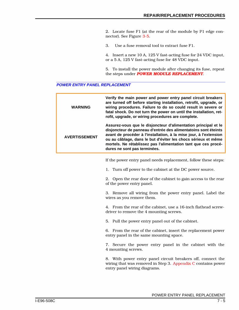
REPAIR/REPLACEMENT PROCEDURES
I-E96-508C
2. Locate fuse F1 (at the rear of the module by P1 edge con-nector). See Figure 3-5.
3. Use a fuse removal tool to extract fuse F1.
4. Insert a new 10 A, 125 V fast-acting fuse for 24 VDC input,or a 5 A, 125 V fast-acting fuse for 48 VDC input.
5. To install the power module after changing its fuse, repeatthe steps under POWER MODULE REPLACEMENT.
POWER ENTRY PANEL REPLACEMENT
If the power entry panel needs replacement, follow these steps:
1. Turn off power to the cabinet at the DC power source.
2. Open the rear door of the cabinet to gain access to the rearof the power entry panel.
3. Remove all wiring from the power entry panel. Label thewires as you remove them.
4. From the rear of the cabinet, use a 16-inch flathead screw-driver to remove the 4 mounting screws.
5. Pull the power entry panel out of the cabinet.
6. From the rear of the cabinet, insert the replacement powerentry panel in the same mounting space.
7. Secure the power entry panel in the cabinet with the4 mounting screws.
8. With power entry panel circuit breakers off, connect thewiring that was removed in Step 3. Appendix C contains powerentry panel wiring diagrams.
WARNING
Verify the main power and power entry panel circuit breakersare turned off before starting installation, retrofit, upgrade, orwiring procedures. Failure to do so could result in severe orfatal shock. Do not turn the power on until the installation, ret-rofit, upgrade, or wiring procedures are complete.
AVERTISSEMENT
Assurez-vous que le disjoncteur d'alimentation principal et ledisjoncteur de panneau d'entrée des alimentatoins sont éteintsavant de procéder à l'installation, à la mise jour, à l'extensionou au câblage, dans le but d'éviter les chocs sérieux et mêmemortels. Ne rétablissez pas l'alimentation tant que ces procé-dures ne sont pas terminées.
POWER ENTRY PANEL REPLACEMENT
7 - 5

REPAIR/REPLACEMENT PROCEDURES ®
9. Set the jumpers on the DC transfer module for the desiredoperation.
10. Set the jumpers and dipswitch on the bus monitor modulefor the desired operation.
11. Turn on the power to the power entry panel at the DCsource.
12. Turn on the power to the cabinet at the power entry panelcircuit breakers and check for proper operation.
POWER ENTRY PANEL REPLACEMENT
7 - 6 I-E96-508C

SECTION 8 - SUPPORT SUERVICES
I-E96-508C
INTRODUCTION
Bailey Controls is ready to help in the use and repair of itsproducts. Contact your nearest sales office to make requestsfor sales, applications, installation, repair, overhaul and main-tenance contract services.
REPLACEMENT PARTS AND ORDERING INFORMATION
When making repairs at your facility, order replacement partsfrom a Bailey sales office. Provide this information:
1. Part description, part number and quantity.
2. Model and serial numbers (if applicable).
3. Bailey Controls instruction manual number, page numberand reference figure that identifies the part.
When you order standard parts, use Bailey Controls part num-bers and descriptions (refer to Table 7-1). Order parts withoutcommercial descriptions from the nearest Bailey Controls salesoffice.
TRAINING
Bailey Controls has a modern training facility that providesservice and repair instruction. On-site training is also avail-able. Contact a Bailey Controls sales office for specific informa-tion and scheduling.
TECHNICAL DOCUMENTATION
Obtain additional copies of this manual from the nearest Baileysales office at a reasonable charge.
INTRODUCTION
8 - 1

APPENDIX A - QUICK REFERENCE MATERIAL
I-E96-508C
INTRODUCTION
Use Table A-1 as a quick reference to check switch and jumpersettings on the, IEPDF01, IEPDF02, IEPDS01 and IEPDS02modules, bus monitor module, and DC transfer module. Fig-ures 3-3, 3-4, and 3-5 show DC transfer module, bus monitormodule, and power module board layout.
Table A-1. Switch and Jumper Setting Reference Guide
DeviceDipswitch Settings
Jumper Position
Function
Bus monitor module
S1-0011 Factory default setting, 5 VDC, ±15 VDC, and 24 VDC monitoring enabled. External power monitoring disabled.
J11-22-42-3
Auxiliary bus monitor, channel 1:Selects 24 VDC external powerSelects 48 VDC external powerSelects 125 VDC external power
J21-22-42-3
Auxiliary bus monitor, channel 2:Selects 24 VDC external powerSelects 48 VDC external powerSelects 125 VDC external power
J32-3 Jumper must be installed in this position
J41-22-33-4
Auxiliary status input 1:Normally open status inputNormally closed status inputPFI (NO)
J51-22-3
Auxiliary status input 2:Normally open status inputNormally closed input
J61-22-3
Input power isolation:Do not isolate input powerIsolate input power
J72-3 Jumper must be installed in this position
J8 1
1-22-3
Input common isolation:Isolate input common from output commonDo not isolate input common from output common
DC transfer module
J11-42-4
Input power, line 1:24 VDC high detect48 VDC high detect
J21-42-4
Input power, line 1:24 VDC low detect48 VDC low detect
INTRODUCTION
A - 1

QUICK REFERENCE MATERIAL ®
DC transfer module (cont.)
J31-42-4
Input power, line 2:24 VDC high detect48 VDC high detect
J41-42-4
Input power, line 2:24 VDC low detect48 VDC low detect
J131-22-3
Input power source:48 VDC24 VDC
All power modules
J2AB
Enable 5 VDC, ±15 VDC, and 24 VDC monitoring Disable ±15 VDC monitoring
J3AB
IEPDS01/02 power module IEPDF01/02 power module
NOTE:1. Jumpers J6 and J8 must have corresponding settings (i.e., both set for isolation or no isolation).
Table A-1. Switch and Jumper Setting Reference Guide (continued)
DeviceDipswitch Settings
Jumper Position
Function
INTRODUCTION
A - 2 I-E96-508C
APPENDIX B - MODULE POWER REQUIREMENTS
I-E96-508C
INTRODUCTION
This section lists the power requirements of INFI 90 modules,and termination unit and modules. Use this information tocalculate the 5 VDC, ±15 VDC and 24 VDC module currentrequirements for each INFI 90 cabinet. The procedure for cal-culating current requirements includes a worksheet for calcu-lating system powered I/O current requirements.
After you calculate the current requirements for each cabinet,calculate the number of modular power supplies needed foreach cabinet by following the instructions under SIZING THEMODULAR POWER SYSTEM. Appendix D provides tables thatallow you to bypass the power system sizing calculations inthis section. Finally, there is a procedure to verify that thetotal current draw of the power cabinet is within the powerentry panel specifications.
CALCULATING CURRENT REQUIREMENTS
Tables B-1 and B-2 contain a list of all INFI 90 modules, termi-nation units and modules and their operating current require-ments. Use Table B-3 to calculate system powered I/O currentrequirements. To use the information in these tables:
NOTE: Current consumption values listed in the tables apply to onemodule. Multiply the value of current consumption per module by thenumber of those modules in the cabinet. For example, if a cabinetcontains four IMASI02 modules, the total 5 VDC current consump-tion of these modules is 4 x 85 mA = 340 mA.
1. Make a list of modules contained in the cabinet you aresizing for modular power supplies.
2. Calculate the 5 VDC current requirement for each cabinet.
a. Refer to Table B-1 for the 5 VDC current requirement ofeach module.
b. Total the 5 VDC current requirement per cabinet.
3. Calculate the +15 VDC current requirement for eachcabinet.
a. Refer to Table B-1 for the +15 VDC current require-ment of each module.
b. Total the +15 VDC current requirement per cabinet.
INTRODUCTION
B - 1

MODULE POWER REQUIREMENTS
4. Calculate the -15 VDC current requirement for each cabi-net.
a. Refer to Table B-1 for the -15 VDC current requirementof each module.
b. Total the -15 VDC current requirement per cabinet.
5. Calculate the 24 VDC current requirement.
a. Refer to Table B-1 for the 24 VDC current requirementfor each module.
b. Table B-2 lists 24 VDC current requirements of termi-nation units and termination modules.
c. Total the 24 VDC current requirement per cabinet.
6. Add the current requirement of any system powered I/Ousing 24 VDC to the total from Step 5c. The procedure underCALCULATING I/O CURRENT REQUIREMENTS gives an over-view of how to calculate the system powered I/O currentrequirement.
Table B-1. DC Current Consumption for INFI 90 Modules
INFI 90Modules
No. of Modules/Cabinet
Current Consumption per Module (mA)
5 VTotal5 V
+15 VTotal +15 V
-15 VTotal-15 V
24 VTotal24 V
IISAC01 0 0 0 530
IMAMM03 725 125 30 0
IMAOM01 1045 0 0 0
IMASI02 95 30 25 0
IMASI03 330 140 40 0
IMASM01 120 85 45 0
IMASM02IMASM03
400 80 40 6
IMASM04 550 45 30 0
IMASO01 530 220 225 50
IMCIS02 300 30 25 7
IMCOM03IMCOM04
660 55 50 7
IMCPM01 0 0 0 0
IMCPM02 825 0 0 0
IMDSI02 60 0 0 0
IMDSM04 1500 0 0 65
IMDSM05 600 0 0 0
Page total
CALCULATING CURRENT REQUIREMENTS
B - 2 I-E96-508C

MODULE POWER REQUIREMENTS
I-E96-508C
IMDSO01IMDSO02IMDSO03
150 0 0 0
IMDSO04 165 0 0 0
IMFBS01 100 30 20 0
IMFCS01 220 7 10 0
IMHSS01IMHSS02
180 80 70 20
IMLMM02 660 0 0 0
IMMFC03 4200 40 20 0
IMMFC04 1400 0 0 0
IMMFC05 1000 0 0 0
IMMFP01IMMFP02
2000 0 0 0
IMMFP03 2000 0 0 0
IMMPC01 4200 40 20 0
IMMPI01 415 0 0 0
IMMPI02 700 0 0 0
IMQRC01 660 55 50 7
IMQRS01IMQRS02
300 30 25 7
IMRIO02 1600 20 90 0
IMSPM01 1330 30 25 0
INBIM01INBIM02INBTM01
1100 0 0 0
INICT01 4200 40 20 0
INICT03 1958 0 0 0
INIIT01 4200 40 20 0
INIIT02INIIT03
2000 0 0 0
INIPT01 4200 40 20 0
INLIM03 2200 90 90 0
INNIS01 900 5 200 0
INNPM01 2000 0 0 0
Page total
Table B-1. DC Current Consumption for INFI 90 Modules (continued)
INFI 90Modules
No. of Modules/Cabinet
Current Consumption per Module (mA)
5 VTotal5 V
+15 VTotal +15 V
-15 VTotal-15 V
24 VTotal24 V
CALCULATING CURRENT REQUIREMENTS
B - 3
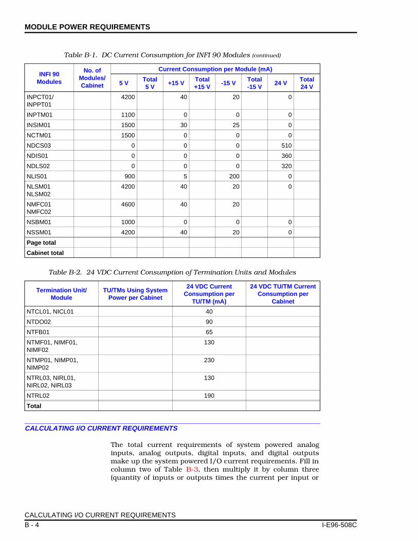
MODULE POWER REQUIREMENTS
CALCULATING I/O CURRENT REQUIREMENTS
The total current requirements of system powered analoginputs, analog outputs, digital inputs, and digital outputsmake up the system powered I/O current requirements. Fill incolumn two of Table B-3, then multiply it by column three(quantity of inputs or outputs times the current per input or
INPCT01/INPPT01
4200 40 20 0
INPTM01 1100 0 0 0
INSIM01 1500 30 25 0
NCTM01 1500 0 0 0
NDCS03 0 0 0 510
NDIS01 0 0 0 360
NDLS02 0 0 0 320
NLIS01 900 5 200 0
NLSM01NLSM02
4200 40 20 0
NMFC01NMFC02
4600 40 20
NSBM01 1000 0 0 0
NSSM01 4200 40 20 0
Page total
Cabinet total
Table B-2. 24 VDC Current Consumption of Termination Units and Modules
Termination Unit/Module
TU/TMs Using System Power per Cabinet
24 VDC CurrentConsumption per
TU/TM (mA)
24 VDC TU/TM Current Consumption per
Cabinet
NTCL01, NICL01 40
NTDO02 90
NTFB01 65
NTMF01, NIMF01, NIMF02
130
NTMP01, NIMP01, NIMP02
230
NTRL03, NIRL01, NIRL02, NIRL03
130
NTRL02 190
Total
Table B-1. DC Current Consumption for INFI 90 Modules (continued)
INFI 90Modules
No. of Modules/Cabinet
Current Consumption per Module (mA)
5 VTotal5 V
+15 VTotal +15 V
-15 VTotal-15 V
24 VTotal24 V
CALCULATING I/O CURRENT REQUIREMENTS
B - 4 I-E96-508C
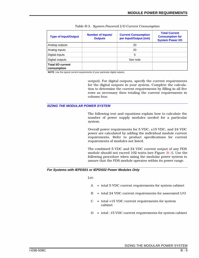
MODULE POWER REQUIREMENTS
I-E96-508C
output). For digital outputs, specify the current requirementsfor the digital outputs in your system. Complete the calcula-tion to determine the current requirements by filling in all fiverows as necessary then totaling the current requirements incolumn four.
SIZING THE MODULAR POWER SYSTEM
The following text and equations explain how to calculate thenumber of power supply modules needed for a particularsystem.
Overall power requirements for 5 VDC, ±15 VDC, and 24 VDCpower are calculated by adding the individual module currentrequirements. Refer to product specifications for currentrequirements of modules not listed.
The combined 5 VDC and 24 VDC current output of any PDSmodule should not exceed 102 watts (see Figure B-1). Use thefollowing procedure when sizing the modular power system toassure that the PDS module operates within its power range.
For Systems with IEPDS01 or IEPDS02 Power Modules Only
Let:
A = total 5 VDC current requirements for system cabinet
B = total 24 VDC current requirements for associated I/O
C = total +15 VDC current requirements for system cabinet
D = total -15 VDC current requirements for system cabinet
Table B-3. System Powered I/O Current Consumption
Type of Input/OutputNumber of Inputs/
OutputsCurrent Consumption per Input/Output (mA)
Total CurrentConsumption forSystem Power I/O
Analog outputs 20
Analog inputs 20
Digital inputs 5
Digital outputs See note
Total I/O currentconsumptionNOTE: Use the typical current requirements of your particular digital outputs.
SIZING THE MODULAR POWER SYSTEM
B - 5

MODULE POWER REQUIREMENTS
Q1 = number of PDS power modules needed to meet 5 and 24 VDC current requirements
Q2 = number of PDS power modules needed to meet +15 VDC current requirements
Q3 = number of PDS power modules needed to meet -15 VDC current requirements
QS = the largest value of Q1, Q2 or Q3
QS(N) = number of PDS power modules needed to power the system
QS(N+1) = number of modules needed for N+1 redundancy, add 1 to the value of QS(N)
The following equations should be used when sizing systemshaving only PDS supplies.
If B ≥ A/5 then Q1 = (A/20) + (B/4)
If B < A/5 then Q1 = A/10
Q2 = C/0.5
Q3 = D/0.5
QS = largest value of Q1, Q2 and Q3
QS(N) = value of QS rounded to the next highest integer = number of PDS power modules required
QS(N+1) = if using N+1 redundancy, add 1 to the value of QS(N)
NOTE: The tables in Appendix D contain calculated values of Q1, Q2and Q3 for various load combinations. These tables enable you tosize the modular power system without doing the sizing calculations.
Figure B-1. Power Output of One IEPDS01/02 Module
OUTPUT CURRENT OF25.5 VDC OUTPUT (AMPS)
OUTPUTCURRENT OF
5.1 VDCOUTPUT(AMPS)
102 WOUTPUT MAX.MAX. POWER
OUTPUT OF PDS
TP25244A
1
0
2.5
5.0
7.5
10.0
2 3 4
SIZING THE MODULAR POWER SYSTEM
B - 6 I-E96-508C

MODULE POWER REQUIREMENTS
I-E96-508C
System Calculation Example Using IEPDS01 or IEPDS02 Power Modules Only
Assume that the current requirements for a set of modulesresiding in a system cabinet have been calculated.
Additionally, the current requirements for 24 VDC I/O powerwere calculated. The results are:
A = 26.5 amps (5 VDC cabinet requirement)
B = 3.1 amps (24 VDC I/O power requirement)
C = 0.9 amps (+15 VDC cabinet requirement)
D = 0.4 amps (-15 VDC cabinet requirement)
Substitute these values into the equations and solve for Q.
Q1 = (26.5/10) because B = 3.1 which is less than A/5 = 26.5/5 = 5.3
Q1 = 2.65
Q2 = 0.9/0.5Q2 = 1.8
Q3 = 0.4/0.5Q3 = 0.8
QS = Largest value of Q1, Q2 and Q3QS = 2.65
Round the value of QS to the next highest integer. This is thenumber of PDS power modules required to power the system.
QS(N) = 3 PDS modules
With N+1 redundancy
QS(N+1) = QS(N) + 1 = 4 PDS modules
For Systems Using Both IEPDS01 and IEPDF01, or IEPDS02 and IEPDF02 Power Modules
Let:
A = total 5 VDC current requirements for system cabinet
B = total 24 VDC current requirements for associated I/O
C = total +15 VDC current requirements for system cabinet
D = total -15 VDC current requirement for system cabinet
SIZING THE MODULAR POWER SYSTEM
B - 7

MODULE POWER REQUIREMENTS
Q1 = number of PDS power modules needed to meet 5 VDC requirements
Q2 = number of PDS power modules needed to meet +15 VDC current requirements
Q3 = number of PDS power modules needed to meet -15 VDC current requirements
Q4 = number of PDF power modules needed to meet 24 VDC current requirements
QS = the largest value of Q1, Q2 and Q3
QS(N) = number of PDS power modules needed to power the system
QF = calculated number of PDF power modules needed to meet associated I/O current requirements
QF(N) = number of PDF power modules needed to meet associated I/O current requirements
QS(N+1) = number of modules needed for N+1 redudancy, add 1 to the value of QS(N)
The following equations should be used when sizing systemshaving both PDS and PDF supplies.
Q1 =If (Q1 - A/10) < 0 then use Q1 = A/10
Q2 = C/0.5
Q3 = D/0.5
QS = largest of Q1, Q2 and Q3
QS(N) = value of QS rounded to the next highest integer = number of PDS modules required
If Q1 = 0 then use QF = B/4
QF = B × [5/(20 - A/QS(N))] - QS(N)
If Q1 = 0 then use QF = B/4
QF(N) = value of QF rounded to the nest highest integer = number of PDF modules required
A B× 80 A2 1600⁄+⁄ A 40⁄+
SIZING THE MODULAR POWER SYSTEM
B - 8 I-E96-508C

MODULE POWER REQUIREMENTS
I-E96-508C
QS(N+1) = if using N+1 redundancy, add 1 to the value of QS(N)
NOTE: The tables in Appendix D contain calculated values of Q1,Q2, Q3 and QF for various load combinations. These tables enableyou to size the modular power system without doing the sizing cal-culations.
System Calculation Example Using IEPDS01 and IEPDF01, or IEPDS02 and IEPDF02 Power Modules
Assume that the current requirements for a set of modulesresiding in a system cabinet has been calculated.
Additionally, the current requirements for 24 VDC I/O powerwas:
A = 26.5 amps (5 VDC cabinet requirement)
B = 12 amps (24 VDC associated I/O requirement)
C = 0.9 amps (+15 VDC cabinet requirement)
D = 0.4 amps (-15 VDC cabinet requirement)
Substitute these values into the equation and solve for Q.
Q1 =Q1 = 2.76
Q2 = 0.9/0.5Q2 = 1.8
Q3 = 0.4/0.5Q3 = 0.8
QS = Largest of Q1, Q2 and Q3QS = 2.76
Round the value of QS to the next highest integer. This is thenumber of PDS power modules required for system.
QS(N) = 3 PDS modules
Calculate the value of QF
QF = 12 x[5/(20 - 26.5/3)] - 3QF = 2.37
Round the value of QF to the next highest integer. This is thenumber of PDF power modules required to power associatedI/O current requirements.
QF(N) = 3 PDF modules
26.5 12×( ) 80 26.52 1600⁄+⁄ 26.5 40⁄+
SIZING THE MODULAR POWER SYSTEM
B - 9

MODULE POWER REQUIREMENTS
With N+1 redundancy
QS(N+1) = QS(N) + 1 = 4 PDS modules
Power module placement is important. For optimum cooling,power modules should not be stacked at one end of the mod-ule mounting unit. See Figure 3-6 for an example of how thepower modules should be positioned in the IEMMU01 andIEMMU02 module mounting units.
NOTE: Place a maximum of two power supply modules in any mod-ule mounting unit, a maximum of 12 modules in any power mountingunit.
MAXIMUM POWER ENTRY PANEL CURRENT DRAW
Add the current draw of all the power modules within the cab-inet to the fan assembly current draw to determine the maxi-mum current draw on the power entry panel. The current drawof each power module is:
• IEPDF01 module, 6.5 amps.• IEPDF02 module, 3.25 amps.• IEPDS01 module, 7.6 amps.• IEPDS02 module, 3.8 amps.
The current draw for each fan assembly is:
• IEFAN03 fan assembly, 1.50 amps.• IEFAN05 fan assembly, 1.32 amps.
The current draw on the power entry panel should be withinits specified limit. The current draw limit on the IEPEP04Power Entry Panel is:
• 60 amps for 24 VDC systems. • 30 amps for 48 VDC systems.
MAXIMUM POWER ENTRY PANEL CURRENT DRAW
B - 10 I-E96-508C

APPENDIX C - WIRING DIAGRAMS
I-E96-508C
INTRODUCTION
Appendix C contains system cabinet wiring diagrams for theIEMMU01 and IEMMU02 Module Mounting Unit and theIEPMU01 and IEPMU02 Power Mounting Unit. Figure C-1shows the IEPEP04 system cabinet wiring diagram for themodule mounting unit. Figure C-2 shows the IEPEP04 systemcabinet wiring diagram for the power mounting unit.
INTRODUCTION
C - 1

WIRING DIAGRAMS ®
+/L1D
D
K
K
L
L
–/L2
PUT
GL
+/L1
+/L1
D
D
D
K
K
K
L
UT POWERBUS BAR
–/L2
–/L2
D
K
L
+/L1
+/L1
–/L2
–/L2
TP50309B
Figure C-1. IEPEP04 System Cabinet Wiring Diagram (Module Mounting Unit)
+
RE
RE
BL
BL
GRN/YE
GRN/YE
CABLE P/N6639443 1(SUPPLIEDWITH PEP)
�
SAFETY GND.CONN. TO CAB.
(–) LINE 2 POWER IN
(+) 24/48 VDC
LINE 1 POWER INPUT (–)
24/48 VDC (+)
DCTRANSFER
BUSMONITOR
STATUSALARMS
AUX BUSMONITOR
GNDFANOUT
PWRSYS+ –
CH1+ –
CH2+ –
L1 IN
OUT
+ – –
++ – –
L2 IN
OUTBUSVOLT+ –
IN1 COM 2
J2
J1
TB2
TB1 1
1
52
2
63
3
74
4
8
NO. 6 AWGRN/YE
RE
RE
RE
BL
BL
BL
GRN/YE
BLK
RED
GRN/YEL
PFI
STATUS
I/O COM
+24 V
+5 V
MCOM
+15 V
–15 V
PFI
STATUS
I/O COM
+24 V
+24 V
I/O COM
NO. 14 AWGCUSTOMER +24 V OUTPUT
TO NEXT MMU
NO. 18 AWG (3-WIRE TWISTED)
MODULE MOUNTING UNITIEMMU01/02ROW 3
MODULE MOUNTING UNITIEMMU01/02ROW 2
FAN ASSEMBLYIEFAN03/05ROW 1
POWER ENTRY PANELIEPEP04ROW 0
NO. 10 AWG
MCOM
+5 V
+5 V
MCOM
MCOM
+15 V
+15 V
–15 V
–15 V
PFI
STATUS
I/O COM
+24 V
RED
BLK
YEL
YEL
YEL
YEL
ORN
ORN
ORNMBUS
MBUS
MBUS
MBUS
MCOM
+24 V
I/O COM
STATUSCABLE P/N1948509 5�
CABLE P/N1948509 5�
CABLE P/N1948509 5�
CABLE P/N1948509 5�
CABLE P/N 6634206 1�
CABLE P/N 6637813C1(SUPPLIED WITH PEP)
PFI
–15 V
+15 V
MCOM
MCOM
+5 V
+24 V
I/O COM
STATUS
PFI
–15 V
+15 V
MCOM
+5 V
WHT
WHT
WHT
ORN
WHT/BLU
WHT/ORN
WHT/ORN
GRAY
GRAY
GRAY
GRAY
SYSTEM POWERBUS BAR
INP
RE
BLK(–)
(+)
BL
RED GRN/YE
GRN/YEL
CABLE P/N6637818 2�
(–)
(+)
CABLE P/N6637818 2�
ISOLATED SYSTEM COMMON BUS
ORN
WHT
USER ALARM OUTPUTPOWER SYSTEM STATUS
USER ALARM OUTPUTBUS VOLTAGE STATUS
NODE STATUSTO BIM/PTM ORNTCL01/NICL01
CUSTOMER AUX BUSMONITOR INPUTS
24/48/125 VDC
STATUSINPUTS
(+)(–)
(+)(–)
(+)(–)
(+)(–)
CH1
CH2
1COM
2
INTRODUCTION
C - 2 I-E96-508C

WIRING DIAGRAMS
I-E96-508C
CUSTOMER AMONITOR INP24/48/125 VDC
RED
WH
WHT/BLU
WHT/ORN
YE
SYSTEPOWE
BUS BA
NODE STATUSO
NTCL01
USER ALARPOWER SYST
USER ALARBUS VOLTA
OR
BLK
OR
Figure C-2. IEPEP04 System Cabinet Wiring Diagram (Power Mounting Unit)
1 2 3 4
AUX BUSMONITOR
CH1 CH2+ - + -
1 2 3 4 5 6 7 8
1 COM 2IN
STATUS ALARMSPWRSYS+ - + -
BUSVOLT FAN
OUTGND
(+)(-)(+)
(-)CH2
CH1UX BUSUTS
1COM
2
(+)(-)(+)(-)
SAFETY GND.CONN. TO CAB.
FAN ASSEMBLYIEFAN03IEFAN05
MCOM
+15 V
-15 V
+5 V
STATUS
I/O COM
+24 V
+5 V
MCOM
+15 V-15 V
PFI
STATUS
+5 V
MCOM
+15 V
-15 V
T
J2
CABLE P/N 6637813_1(SUPPLIED WITH PEP)
CABLE P/N1948509-5
CABLE P/N1948509-5
MCOM
+15 V
-15 V
+5 V
PFISTATUS
I/O COM+24 V
MBUS
MBUS
MCOM
+5 V
MCOM
+15 V
-15 VPFI
STATUSI/O COM
+24 V
ORN
YEL
WHT
18 AWG (3-WIRE TWISTED)
10 AWG
ISOLATED SYSTEM COMMON BUS
+24 V
I/O COM
MCOM
WHT/ORN
GRAY
GRAY
GRAY
GRAY
CUSTOMER +24 V OUTPUT14 AWG
TO NEXT MMU
L PFISTATUS
I/O COM+24 V
MRR
J1
OUT OUT
L1 IN L2 IN
(-)(+)
(-)(+)
DCTRANSFER
BUSMONITOR
TB1
TO BIM/PTMR/NICL01
M OUTPUTEM STATUSM OUTPUTGE STATUS
(-)(+)
GRN/YEL
N
N
POWER MOUNTING UNITIEPMU01IEPMU02
10 AWG
TP25146B
MODULE MOUNTING UNITIEMMU01 ROW 3IEMMU02
POWER ENTRY PANELIEPEP04 ROW 0
DC IN/COM
24 V/48 V IN
BLK
RED
CABLE P/N6639443-2
6 AWG GRN/YEL
TB2
I/O COM
6632285A486632285A48
+24 V
CABLE P/N 6634205-1
LINE 1 POWER INPUT24/48 VDC
LINE 2 POWER INPUT24/48 VDC
STATUSINPUTS
6632285A456632285A47
I/O COM
+24 V
6632285A49
6632285A46+5 V
MCOM
ROW 2
ROW 1
-
-
-
-
+
+
+
+
INTRODUCTION
C - 3

APPENDIX D - MODULAR POWER SYSTEM SIZING TABLES
I-E96-508C
INTRODUCTION
The tables in this appendix enable you to size the modularpower system and bypass the calculations required by the siz-ing procedure in Appendix B. Use Table D-1 to size power sys-tems that have only IEPDS01 and IEPDS02 modules. To usethe tables, first determine the current requirements for thecabinet (refer to Appendix B). Shown in the table are values forA (5 VDC current requirement for the cabinet) and B (24 VDCcurrent requirement for the cabinet). The box intersected bythe requirements of A and B shows the number of PDS mod-ules needed.
Table D-1. Q1 for Systems Using IEPDS01/02 Modules Only
AB
0 2 4 6 8 10 12 14 16 18 20 22 24 26 28 30
0 0 1 1 2 2 3 3 4 4 5 5 6 6 7 7 8
5 1 1 2 2 3 3 4 4 5 5 6 6 7 7 8 8
10 1 1 2 2 3 3 4 4 5 5 6 6 7 7 8 8
15 2 2 2 3 3 4 4 5 5 6 6 7 7 8 8 9
20 2 2 2 3 3 4 4 5 5 6 6 7 7 8 8 9
25 3 3 3 3 4 4 5 5 6 6 7 7 8 8 9 9
30 3 3 3 3 4 4 5 5 6 6 7 7 8 8 9 9
35 4 4 4 4 4 5 5 6 6 7 7 8 8 9 9 10
40 4 4 4 4 4 5 5 6 6 7 7 8 8 9 9 10
45 5 5 5 5 5 5 6 6 7 7 8 8 9 9 10 10
50 5 5 5 5 5 5 6 6 7 7 8 8 9 9 10 10
55 6 6 6 6 6 6 6 7 7 8 8 9 9 10 10 11
60 6 6 6 6 6 6 6 7 7 8 8 9 9 10 10 11
65 7 7 7 7 7 7 7 7 8 8 9 9 10 10 11 11
70 7 7 7 7 7 7 7 7 8 8 9 9 10 10 11 11
75 8 8 8 8 8 8 8 8 8 9 9 10 10 11 11 12
80 8 8 8 8 8 8 8 8 8 9 9 10 10 11 11 12
85 9 9 9 9 9 9 9 9 9 9 10 10 11 11 12 12
90 9 9 9 9 9 9 9 9 9 9 10 10 11 11 12 12
95 10 10 10 10 10 10 10 10 10 10 10 11 11 12 12 13
100 10 10 10 10 10 10 10 10 10 10 10 11 11 12 12 13
INTRODUCTION
D - 1

MODULAR POWER SYSTEM SIZING TABLES ®
Use Table D-2 to size systems that use both the IEPDS01 andIEPDS02 and IEPDF01 and IEPDF02 modules. Table D-2 liststwo values (Q1 and QF) for the 5 VDC and 24 VDC (A and B)current requirements. The value of Q1 indicates how manyPDS modules are needed to meet system requirements. Thevalue of QF indicates how many PDF modules are needed tomeet system requirements.
Table D-2. Q1 and QF for Systems Using IEPDS01/02 and IEPDF01/02 Modules
AB
0 2 4 6 8 10 12 14 16 18 20 22 24 26 28 30
0 Q1 0 0 0 0 0 0 0 0 0 0 0 0 0 0 0 0
QF 0 1 1 2 2 3 3 4 4 5 5 6 6 7 7 8
5 Q1 1 1 1 1 1 1 1 2 2 2 2 2 2 2 2 2
QF 0 0 1 1 2 2 3 3 4 4 5 5 6 6 7 7
10 Q1 1 1 1 2 2 2 2 2 2 2 2 2 2 3 3 3
QF 0 0 1 0 1 2 2 3 4 4 5 6 6 5 6 6
15 Q1 2 2 2 2 2 2 2 3 3 3 3 3 3 3 3 3
QF 0 0 0 1 2 2 3 2 3 3 4 5 5 6 7 7
20 Q1 2 2 2 2 2 3 3 3 3 3 3 3 3 4 4 4
QF 0 0 0 1 2 1 2 3 3 4 5 6 6 5 6 6
25 Q1 3 3 3 3 3 3 3 3 3 4 4 4 4 4 4 4
QF 0 0 0 0 1 2 3 3 4 3 4 4 5 6 7 7
30 Q1 3 3 3 3 3 3 3 4 4 4 4 4 4 4 5 5
QF 0 0 0 0 1 2 3 2 3 4 4 5 6 7 5 6
35 Q1 4 4 4 4 4 4 4 4 4 4 4 5 5 5 5 5
QF 0 0 0 0 0 1 2 3 4 4 5 4 5 5 6 7
40 Q1 4 4 4 4 4 4 4 4 4 5 5 5 5 5 5 5
QF 0 0 0 0 0 1 2 3 4 3 4 5 5 6 7 8
45 Q1 5 5 5 5 5 5 5 5 5 5 5 5 5 6 6 6
QF 0 0 0 0 0 0 1 2 3 4 5 5 6 5 6 6
50 Q1 5 5 5 5 5 5 5 5 5 5 5 6 6 6 6 6
QF 0 0 0 0 0 0 1 2 3 4 5 4 5 6 6 7
55 Q1 6 6 6 6 6 6 6 6 6 6 6 6 6 6 6 7
QF 0 0 0 0 0 0 0 1 2 3 4 5 6 6 7 6
60 Q1 6 6 6 6 6 6 6 6 6 6 6 6 6 7 7 7
QF 0 0 0 0 0 0 0 1 2 3 4 5 6 5 6 7
65 Q1 7 7 7 7 7 7 7 7 7 7 7 7 7 7 7 7
QF 0 0 0 0 0 0 0 0 1 2 3 4 5 6 7 7
70 Q1 7 7 7 7 7 7 7 7 7 7 7 7 7 7 7 8
QF 0 0 0 0 0 0 0 0 1 2 3 4 5 6 7 6
75 Q1 8 8 8 8 8 8 8 8 8 8 8 8 8 8 8 8
QF 0 0 0 0 0 0 0 0 0 1 2 3 4 5 6 7
INTRODUCTION
D - 2 I-E96-508C

MODULAR POWER SYSTEM SIZING TABLES
I-E96-508C
Use Table D-3 to determine the value of Q2 using C (the +15VDC current requirements for the cabinet) and Q3 using D (the-15 VDC current requirements for the cabinet).
80 Q1 8 8 8 8 8 8 8 8 8 8 8 8 8 8 8 8
QF 0 0 0 0 0 0 0 0 0 1 2 3 4 5 6 7
85 Q1 9 9 9 9 9 9 9 9 9 9 9 9 9 9 9 9
QF 0 0 0 0 0 0 0 0 0 0 1 2 3 4 5 6
90 Q1 9 9 9 9 9 9 9 9 9 9 9 9 9 9 9 9
QF 0 0 0 0 0 0 0 0 0 0 1 2 3 4 5 6
95 Q1 10 10 10 10 10 10 10 10 10 10 10 10 10 10 10 10
QF 0 0 0 0 0 0 0 0 0 0 0 1 2 3 4 5
100 Q1 10 10 10 10 10 10 10 10 10 10 10 10 10 10 10 10
QF 0 0 0 0 0 0 0 0 0 0 0 1 2 3 4 5
Table D-2. Q1 and QF for Systems Using IEPDS01/02 and IEPDF01/02 Modules (continued)
AB
0 2 4 6 8 10 12 14 16 18 20 22 24 26 28 30
Table D-3. Q2 or Q3 for All Power Systems
Q2 or Q3
C or D
0 0.5 1 1.5 2 2.5 3 3.5 4 4.5 5 5.5 6
0 1 2 3 4 5 6 7 8 9 10 11 12
INTRODUCTION
D - 3

Index
B
Bus monitor module ................................................... 2-3Jumper settings .................................................... 3-8LEDs..................................................................... 4-2Removal................................................................ 4-2Replacement......................................................... 7-2
C
Checking connections ................................................ 6-4Cleaning
Cabinet filter.......................................................... 6-3Edge connectors................................................... 6-6Printed circuit boards............................................ 6-6
D
DC transfer module .................................................... 2-3Jumper settings .................................................... 3-7LEDs..................................................................... 4-1Removal................................................................ 4-2Replacement......................................................... 7-2
Documentation .................................................... 1-5, 8-1
F
Fan assembly ............................................................. 2-4Fuse...................................................................... 7-1
Fuse ratings................................................................ 7-1
G
Glossary of terms and abbreviations.......................... 1-4
I
I/O current requirements ............................................B-4Installation .................................................................. 3-2
Bus monitor module.............................................. 3-7DC transfer module............................................... 3-6Fan assembly ....................................................... 3-9Power entry panel................................................. 3-3Power mounting unit ........................................... 3-11
J
Jumper setting reference............................................A-1
M
Maintenance........................................................ 6-1, 6-2Modular power system
Description..................................................... 1-1, 2-1
Handling ................................................................3-1Operation ..............................................................4-1Sizing ................................................................... B-1Specifications ........................................................1-5
ModuleCurrent requirements ........................................... B-1Mounting unit.........................................................2-4Power requirements ............................................. B-1
N
Nomenclature..............................................................1-4
P
Part numbers ..............................................................7-1Parts list ......................................................................7-1Parts ordering .............................................................8-1Power entry panel .......................................................2-3
Installation .............................................................3-3Wiring ....................................................................3-3
Power moduleChecking outputs ..................................................6-4Fuse ......................................................................7-1Fuse replacement .................................................7-4Jumper settings.....................................................3-9LEDs .....................................................................4-2Replacement .........................................................7-1Sizing procedures ................................................ B-1
Power mounting unit ...................................................2-4Power system sizing ...........................................B-1, D-1Preventive maintenance ......................................6-1, 6-2
Procedures............................................................6-3Schedule ...............................................................6-2
Q
Quick reference.......................................................... A-1
S
Special handling..........................................................3-1Specifications..............................................................1-5Start-up .......................................................................4-2Switch setting reference............................................. A-1System status and alarms...........................................2-5
T
Training .......................................................................8-1Troubleshooting ..........................................................5-1
Flowchart...............................................................5-3
I-E96-508C Index - 1

29801 Euclid Avenue • Wickliffe, Ohio 44092 • (216) 585-8500Telex: 980621 • Telefax: (216) 585-8756 or (216) 943-4609
Elsag Ba ileyProcess Automat io n
For prompt, personal attention to your instrumentation and control needs or a full listing of Bailey representatives in principal cities around the world, contact the Bailey location nearest you.
AustraliaElsag Bailey Pty. LimitedRegents Park, NSWPhone: 61-2-645-3322Telefax: 61-2-645-2212
JapanBailey Japan Company, Ltd.Tagata-Gun, Shizuoka-KenPhone: 81-559-49-3311Telefax: 81-559-49-1114
United KingdomBailey Automation plcTelford, ShropshirePhone: 44-1952-670-477Telefax: 44-1952-670-455
BrazilBailey do BrasilSão PauloPhone: 55-11-548-4122Telefax: 55-11-547-0315
JordanBailey Controls JordanAmmanPhone: 962-6-788-116Telefax: 962-6-756-908
United StatesBailey Controls CompanyWickliffe, OhioPhone: 1-216-585-8500Telefax: 1-216-585-8756
CanadaElsag Bailey (Canada), Inc.Burlington, OntarioPhone: 1-905-639-8840Telefax: 1-905-639-8639
MexicoBailey Mexico S.A. de C.V.NaucalpanPhone: 52-5-557-6100Telefax: 52-5-557-7022
VenezuelaBailey de Venezuela SAValenciaPhone: 58-41-329-196Telefax: 58-41-327-632
FranceElsag Bailey S.A.MassyPhone: 33-1-64-47-2000Telefax: 33-1-64-47-2016
NorwayBailey Norge A.S.BergenPhone: 47-55-222-000Telefax: 47-55-222-010
GermanyBailey-F & P Automation GmbHOverath Phone: 49-220-473-90Telefax: 49-220-473-979
People’s Republic of ChinaBailey Beijing ControlsBeijingPhone: 86-10-401-0651Telefax: 86-10-401-1643
ItalyElsag BaileyGenoaPhone: 39-10-658-1Telefax: 39-10-658-2941
SingaporeElsag Bailey Pte. Ltd.SingaporePhone: 65-442-3200Telefax: 65-442-2700
Form I-E96-508C Litho in U.S.A. 1293Copyright © 1993 by Elsag Bailey Process Automation, As An Unpublished Work® Registered Trademark of Elsag Bailey Process Automation™ Trademark of Elsag Bailey Process Automation