dc motor driver solutions
TRANSCRIPT

DISTRI TOOL 2H12
DC Motor Driver Solutions

DISTRI TOOL 2H12
• Overview
• Summary of DC motor types
– Advantages / disadvantages
– Drive topology
• Basic motor drivers
– Brushed
• BLDC motor drivers
– 3 phase (fan drivers)
– 1/2 phase
• Stepper motor drivers
• Focus products
• Sanyo HID focus products
Agenda

DISTRI TOOL 2H12
DC Motor Family Tree
www.onsemi.com
MECHANIC COMMUTATION ELECTRONIC COMMUTATION
DC MOTORS
- SHUNT WOUND
- SERIES WOUND
- COMPOUND WOUND
- 1 PHASE
- 2 PHASE
- 3 PHASE
- VARIABLE RELUCTANT
- PERMANENT MAGNET
- HYBRID
BRUSHED
WOUND FIELD PERMANENT
MAGNET
BRUSHLESS
ROTATIONAL STEPPER

DISTRI TOOL 2H12
DC Motor Family Tree
DC MOTORS
- SHUNT WOUND
- SERIES WOUND
- COMPOUND WOUND
- 1 PHASE
- 2 PHASE
- 3 PHASE
- VARIABLE RELUCTANT
- PERMANENT MAGNET
- HYBRID
BRUSHED
WOUND FIELD PERMANENT
MAGNET
BRUSHLESS
ROTATIONAL STEPPER

DISTRI TOOL 2H12
Brushed – Permanent Magnet

DISTRI TOOL 2H12
Brushed – Permanent Magnet

DISTRI TOOL 2H12
Brushed – Permanent Magnet

DISTRI TOOL 2H12
Brushed – Permanent Magnet

DISTRI TOOL 2H12
Brushed – Permanent Magnet
• Advantages
– Simple to drive
– Easy speed control
– Relative simple contruction
• Disadvantages
– Brushes wear
– Brushes arc and produce EMC
– Rotor has relative large enertia
– Commutator increases the length of the motor
– Coils are rotating inside the stator and are difficult to cool

DISTRI TOOL 2H12
DC motors
• The Direct Current Family tree
DC MOTORS
- SHUNT WOUND
- SERIES WOUND
- COMPOUND WOUND
- 1 PHASE
- 2 PHASE
- 3 PHASE
- VARIABLE RELUCTANT
- PERMANENT MAGNET
- HYBRID
BRUSHED
WOUND FIELD PERMANENT
MAGNET
BRUSHLESS
ROTATIONAL STEPPER

DISTRI TOOL 2H12
Brushless – 3 Phase

DISTRI TOOL 2H12
Brushless – 3 Phase

DISTRI TOOL 2H12
Brushless – 2 Phase Fan

DISTRI TOOL 2H12
Brushless – Rotational
• Advantages
– Very simple construction
– No moving electrical contacts
– Very reliable
• Disadvantages
– Rather complex electronic commutation:
• Hall sensors
• Drivers
– Difficult speed control
• Requires a microcontroller

DISTRI TOOL 2H12
DC motors
• The Direct Current Family tree
DC MOTORS
- SHUNT WOUND
- SERIES WOUND
- COMPOUND WOUND
- 1 PHASE
- 2 PHASE
- 3 PHASE
- VARIABLE RELUCTANT
- PERMANENT MAGNET
- HYBRID
BRUSHED
WOUND FIELD PERMANENT
MAGNET
BRUSHLESS
ROTATIONAL STEPPER

DISTRI TOOL 2H12
What is a Stepper Motor ?
• In Theory, a Stepper motor is a marvel in simplicity. It
has no brushes, or contacts. Basically it's a synchronous
motor with the magnetic field electronically switched to
rotate the armature magnet around.
• It converts digital pulses into mechanical shaft rotation.
• In other words: it is a digital motor
DISTRI TOOL 2H12
Stepper Motor Types
• 3 basic versions, different in construction based on the use
of permanent magnets and/or iron rotors with laminated
steel stators:
– Permanent magnet
– Variable reluctance
– Hybrid

DISTRI TOOL 2H12
Stepper Motor Types
• 3 basic versions, different in construction based on the use
of permanent magnets and/or iron rotors with laminated
steel stators:
– Permanent magnet
– Variable reluctance
– Hybrid

DISTRI TOOL 2H12
Hybrid Type

DISTRI TOOL 2H12
Examples of Hybrid Type

DISTRI TOOL 2H12
How to make a stepper run
• We concentrate further on 2 phase stepper motors
• How many wires:
– 4 = unifilar
– 6 = bifilar
– 8 = “super”bifilar

DISTRI TOOL 2H12
Stepper Motor Windings
• Unifilar:
– Only one winding per stator pole
– Difficult to drive because coil current direction needs to be
reversed
– Stepper motors with a Unifilar winding will have 4 lead wires.
M

DISTRI TOOL 2H12
Stepper Motor Windings
• Bifilar
– two identical sets of windings on each stator pole
– Easy to drive because no need to change current direction in
the windings. This configuration simplifies operation in that
transferring current from one coil to another one,
– Stepper motors with a Bifilar winding will have 6 to 8 lead
wires
M M

DISTRI TOOL 2H12
How to drive a Unifilar winding?
• Bipolar drive using a H-bridge
H I
I
V+
I
V+
I

DISTRI TOOL 2H12
Electronic commutation
• Alternating current – alternating the currents through coils A and B makes rotor turn
iA
iB
t
t

DISTRI TOOL 2H12
How to increase the resolution?
• Buy a high resolution motor:
– Variable reluctant
– Hybrid

DISTRI TOOL 2H12
Improve resolution: Variable Reluctant Motor

DISTRI TOOL 2H12
How to increase the resolution?
• Buy a high resolution motor:
– Variable reluctant
– Hybrid
• Drive the motor in a clever way
– Introducing micro-step

DISTRI TOOL 2H12
Micro-step: Half step mode
• Alternating current – In half step the resolution improves
Coil A
Coil B
t
t
iA
iB

DISTRI TOOL 2H12
A view on reality (1)
• Half-step Alternating current
– Time stamp: X = 10 ms/div Y = 200 mA/div

DISTRI TOOL 2H12
A view on reality (1)
• Half-step Alternating current
– XY plot: X = 200 mA/div Y = 200 mA/div
Icoil X
Icoil Y

DISTRI TOOL 2H12
A view on reality (2)
• 1/4th-step Alternating current
– Time stamp: X = 10 ms/div Y = 200 mA/div

DISTRI TOOL 2H12
A view on reality (2)
• 1/4th-step Alternating current
– XY plot: X = 200 mA/div Y = 200 mA/div
Icoil X
Icoil Y

DISTRI TOOL 2H12
A view on reality (3)
• 1/8th-step Alternating current
– Time stamp: X = 10 ms/div Y = 200 mA/div
DISTRI TOOL 2H12
A view on reality (3)
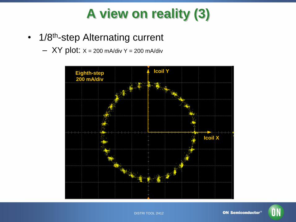
• 1/8th-step Alternating current
– XY plot: X = 200 mA/div Y = 200 mA/div
Icoil X
Icoil YEighth-step
200 mA/div

DISTRI TOOL 2H12
A view on reality (4)
• 1/16th-step Alternating current
– Time stamp: X = 10 ms/div Y = 200 mA/div

DISTRI TOOL 2H12
A view on reality (4)
• 1/16th-step Alternating current
– XY plot: X = 200 mA/div Y = 200 mA/div
Icoil X
Icoil Y

DISTRI TOOL 2H12
How to control the current level
• By using Pulse Width Modulation (PWM)
• Switches in H-bridge are chopping the voltage across the coil:
I
V+
Fixed to
GNDPWM
PWM
PWM
PWM
I
t
t
t
When the battery voltage is across the coil the current increase → called rise
I
V+
Fixed to
GNDPWM
PWM
PWM
PWM
I
t
t
t
When the coil is shorted the current decrease → called decay

DISTRI TOOL 2H12
Slow
Decay_1
t_off
Fast Decay
Slow
Decay_2
Setpoint level
comparator toggled
t_on
PWM I-regulator with mixed decay
Setpoint level
comparator toggled
t_on
Slow
Decay_1
Setpoint level
comparator toggled
t_on
Slow
Decay_1
Fast Decay
Setpoint level
comparator toggled
t_on
Slow
Decay_1
t_off
Fast Decay
Slow
Decay_2
Setpoint level
comparator toggled
t_on
t_on + t_off = T = cte

DISTRI TOOL 2H12
t
PC20051123.4
Coil X
Coil Y
Ix
Iy
How to control the current level
• Implemented on a full cycle
PWM regulation
Current in 1/16th
micro stepping

DISTRI TOOL 2H12
Focus Motor Drivers

DISTRI TOOL 2H12
ONSEMI.com Selector Guide

DISTRI TOOL 2H12
• Vcc: supply voltage for controller
• Vm: motor supply voltage
• Io: output current
• Step Resolution
• Control type
• Feedback Method: used for closed loop positional control
• Current sense: what is used to confirm drive current/fault
• Fault detection: what faults are detected/observed
Key Selector Columns

DISTRI TOOL 2H12
Sanyo LV8860V
ON Target

DISTRI TOOL 2H12
LV8860V: Target Market
LV8860V: 24V single phase motor driver with PWM speed control.
No other products can control speed in this voltage range where working
voltage and heat generation are high.
Target
・ For cooling fans of office automation equipments
For factory automation equipments
24V operating conditions
・ For projectors
High temperature operating conditions
・ For 12V fan which requires the pulse test for high voltage.
High voltage operating conditions
・ Household electrical appliances (rice cookers, IH machines, toilet
seats, etc)

DISTRI TOOL 2H12
★ New drive system
Noise reduction PWM drive is adopted. ・Features noise reduction, high efficiency,
and kickback reduction all together.
★ Low power consumption and low heat generation ・BiDC process
・Low ON resistance (high and low Ron = 1.4Ω)
・Synchronous rectification
★ Small package ・ SSOP16 ( 6.4mmx5.2mmx1.3mm ) Small mounting area
★High voltage (Vccmax = 36V)
Wide operating temperature range (-40 to 95°C)
★Speed control with PWM input
Feature of LV8860V
Evaluation
board
Simple and easy-to-use!
High safety!
High efficiency!
Low Consumption!
LV8860VGEVB
DISTRI TOOL 2H12
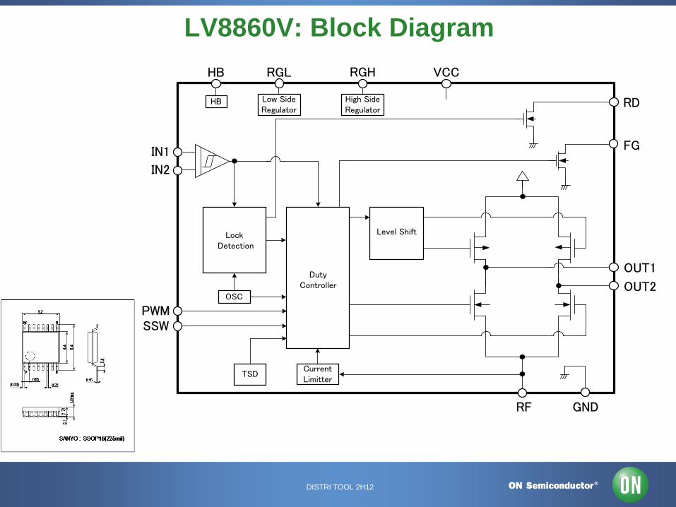
LV8860V: Block Diagram
TSD
Lock Detection
OSC
HB
Duty Controller
Low SideRegulator
High SideRegulator
Level Shift
CurrentLimitter
IN1
IN2
OUT1
OUT2
VCC
RD
RF
HB RGL RGH
FG
GND
PWMSSW

DISTRI TOOL 2H12
LV8860V: Pin Names and Functions Pin No. Pin name Description
1 OUT1 Output pin for motor driver
16 OUT2 The motor coil is connected between OUT1 (pin1) and OUT2 (16pin).
2,3 NC NC pin
Power supply pin
VCC voltage is impressed. The operation voltage range is from 7.0 to 34.0(V).
The capacitor is connected to GND pin (14pin) for stabilization.
Regulator voltage output pin for the upper output Tr driver
The capacitor is connected to VCC pin (3pin) for stabilization.
Input pin for PWM control
The PWM signal is supplied for speed control.
* OPEN: pull up to High
* When input is High output is High
When input is Low output is Low
FG(rotation detection) pulse output pin
The resistor is connected to VCC pin (3pin) for detection signal.
RD(lock detection) signal output pin
*During rotation output is Low , During lock output is High
The resistor is connected to VCC pin (3pin) for detection signal.
Hall input + pin & Hall input – pin
The Hall device outputs are connected.
11 IN2 If hall signal is affected by noise, the capacitor should be connected between IN1 pin (9pin) and IN2 pin (11pin).
Hall bias output pin
The voltage supply pin of Hall device is connected.
Regulator voltage output pin for internal circuit and lower output Tr driver
The capacitor is connected to GND pin (14pin) for stabilization.
Voltage input pin for control between soft switches
The resistor is connected to for RGL or GND pin (14pin) for adjusting soft switch width.
*OPEN: pin voltage is 2V
*Soft switch zone is changed by connecting a resistance to RGL or GND to adjust pin voltage.
14 GND Ground pin
Resistive connection pin for current limiter
The resistor is connected to GND (14pin) for detection of current value.
15 RF
10 HB
12 RGL
13 SSW
7 FG
8 RD
9 IN1
4 VCC
5 RGH
6 PWM

DISTRI TOOL 2H12
LV8860VGEVB
Evaluation Board
Board size: 45 x 45 x 1.6mm Glass epoxy double layer
board
Evaluation board schematic
FG(FG signal output)
RD(RD signal output)
PWM(Speed control signal input terminal)
13
12
11
10
9
4
5
6
7
8 IN1
IN2
OUT2
VCC
RD
RF
HB
RGLRGH
3
2
1
14
15
16
FG
(NC) GND
PWM
SSW
(NC)
OUT1
R210kΩ
R310kΩ
C11uF
C20.1uF
R11Ω
C30.1uF
VCC(Power supplyInput terminal)
Moto
r connection t
erm
inal
LV8860V
Halldevice
Motor Substrate
C1:VCC bypass capacitorChip Laminated Ceramic Capacitor1uF(size:0805)
C2:RGL stabilization capacitorChip Laminated Ceramic Capacitor0.1uF(size:1608)
C3:RGH stabilization capacitorChip Laminated Ceramic Capacitor0.1uF(size:1608)
VCC(Motor and IC Power Supply)
PWM(Speed Control Signal Supply)
R1:Sense ResistorChip Resistor1Ω(size:0603)
R2,R3:Pull-up ResistorChip Resistor1Ω(size:1608)

DISTRI TOOL 2H12
For Single Phase Motor Driver : LV8860V
• LV8860V • Single phase fan motor driver
• Silent PWM drive
Features
・VM max : 36V / Io max : 0.7A
・Low power consumption, low heat generation
・MOS output transistor
(upper + lower Ron = 1.4 ohm typ.)
・silent drive, high efficiency, reduced kickback
・Small-size package SSOP16 (225mil)
(External dimensions : 6.4mm x 5.2mm)
・Protection functions
Lock Protector , Current limiter , Under-voltage,
Thermal protection
LV8860V valued
conservation of energy. Under Mass Production (MP)
TSD
Lock Detection
OSC
HB
Duty Controller
Low SideRegulator
High SideRegulator
Level Shift
CurrentLimitter
IN1
IN2
OUT1
OUT2
VCC
RD
RF
HB RGL RGH
FG
GND
PWMSSW

DISTRI TOOL 2H12
Stepper Motor Driver Alignment

DISTRI TOOL 2H12
LB11847
LB1847
LB11946
AMIS30542
AMIS30532
AMIS3052x
AMIS30512
AMIS3062x
Stepper Motor Current vs. Voltage
2-7V 9-18V 18-30V 40-50V
0.8
1.5
3
5
> 5
A AMIS3042x
(Pre-Driver)
Consumer Automotive
<1.5 A
Industrial 1.5 A– 6A
> 6A
Medical 1.5 A– 3A
LV874x
LV873x
LV854x
LV84xx
LV871x
LV80xx
LV84xx

DISTRI TOOL 2H12
LV8414 LV8713
Stepper Motor Current vs. Step Resolution
2 4 8 16 32 64 128 256 …
0.8
1.5
3
5
> 5
A
Micro Steps
AMIS3042x
(Pre-Driver)
AMIS305xx
Consumer Automotive
<1.5 A
Industrial 1.5 A– 6A
> 6A
Medical 1.5 A– 3A
LV873x
AMIS3062x

DISTRI TOOL 2H12
LV8713
AMIS30542
AMIS30532
AMIS3052x
AMIS30512
Stepper Motor Power vs. Features
Basic Simplified Control High Res Sensor-Less
8
20
40
80
> 100
W AMIS3042x
(Pre-Driver)
LV874x
LV873x
LV871x
LV84xx
LV80xx
LV854x
AMIS3062x
LV8702
No ext.
controller

DISTRI TOOL 2H12
Sanyo LV854x Family
ON Target

DISTRI TOOL 2H12
★Drastic reduction of power consumption ・Current consumption during standby is 0
extremely low power consumption
・ DMOS process and low RON
Low heat and high efficiency
★Small Package ・ MFP10S (5.35×4.4=23.54m㎡) Small mounting area
★High safety ・ Margin for VM (20V) Few IC destruction
・ DMOS process No penetration current
★Based on time-proven results ・The pin is compatible with LB1948M that received a favorable reception
from a Japanese major manufacturer as the standard of damper motor IC.
★2 motor driver functions. ・Usable as stepping motor driver or forward reverse DC motor driver.
Feature of LV8548M
Evaluation
board
Simple and easy-to-use!
High safety!
High efficiency!
Low Consumption!

DISTRI TOOL 2H12
Parameter LV8548M TB6552FN
Toshiba
Merit of LV8548M
Package MFP10S
5.0mm x 6.4mm x 1.7mm
SSOP16
5.5mm x 6.4mm×1.6mm
Mounting area reduced by 10%
approx.
Pin count 10 pin 16 pin Easy pattern layout
Pin pitch 1.0mm 0.65mm Fat pattern layout effective for
high current operation
Power Device DMOS Pch/Nch output DMOS Pch/Nch output
External parts capacitor x 1 capacitor x 2 Few external parts
(power line capacitor included)
Supply Voltage (max ) 20.0V (VM) 15.0V (VM)
6.0V (VCC)
LV8548M has single power
supply, enough margin for max.
voltage
Output Current (max ) 1.0A 1.0A
Output ON Resistance
Sink + Source
Ron:1.0Ωtyp (at 0.8A) Ron:1.5Ωtyp (at 0.8A) Small loss in output TR
Power dissipation: - 33%
Supply Current 1.5mA typ ? mA typ (VM)
0.9mA typ (VCC)
TB6552FN current of VM line
is unknown
STBY Supply Current 1μA max 1μA max (VM)
10μA max (VCC)
Control input pins 2 pin/ch 4 pin/ ch Microcontroller output port
reducible
External PWM input Feasible Feasible
TSD, UVLO Available W/ o UVLO
Cross Reference: LV8548M and TB6552FN

DISTRI TOOL 2H12
OUTPUT
LV8548M: Block Diagram and Main Functions
Motor driver
output
Driver
control
input pin
LV8548M requires no external part for driver circuit (except
for capacitor of power line)
INPUT

DISTRI TOOL 2H12
LV8548M: Full Step Timing
V OUT1
(PhaseA)
IN1
V OUT3
(PhaseB)
IN2
IN3
IN4
OUT1→2
← Outwards Inwards →
ST
EP
ST
EP
ST
EP
ST
EP
ST
EP
ST
EP
Steps by 90deg
① ② ③ ④ ①④
+
+
ー
ー
②
OUT1→2
OUT2→1
OUT3→4 OUT3→4
OUT4→3
①
②
④
③
Phase A +
Phase B –
LV8548M Full Step Timing Motor electric angle
(Full Step Drive)
90deg
Phase A +
Phase B +
Phase A –
Phase B –
Phase A –
Phase B +
1Step Motor advances by 90°of electric angle

DISTRI TOOL 2H12
LV8548M Half Step Timing
V OUT1
(PhaseA)
IN1
V OUT2
(PhaseB)
IN2
IN3
IN4
OUT1→2 OUT1→2
OUT2→1
← Outwards Inwards →
ST
EP
ST
EP
ST
EP
ST
EP
ST
EP
ST
EP
ST
EP
ST
EP
ST
EP
ST
EP
ST
EP
Steps by 45deg
① ② ③ ④ ⑤ ⑥ ⑦ ⑧ ① ② ③⑧
+
+
ー
ー
OUT1→2 OUT1→2
OUT2→1
OFF OFF OFF
OFF OFF OFF
Phase A +
Phase B OFF
Phase A OFF
Phase B +
Phase A +
Phase B +
Phase A –
Phase B +
① ②
③
④
⑧
⑤ ⑥
⑦
Phase A –
Phase B OFF
Phase A –
Phase B –
Phase A OFF
Phase B –
Phase A –
Phase B –
LV8548M Half Step Timing
45deg
Motor electrical angle
(Half Step Drive)
½ Step Motor advances by 45°of electrical angle

DISTRI TOOL 2H12
LV8548M External Application and Waveform of Each Mode
Easy Layout: Only needs capacitor
as external part!
LV8548M: External Application
Please refer to ne x t page for
details.
1 2 3 4 5
10 9 8 7 6
VC
C
IN2
IN3
IN4
IN1
OU
T1
OU
T2
OU
T3
OU
T4
GN
D
LV8548M
10uF +
Logic input
M
VCC
LV8548M Full-Step VCC=12V 200pps
IOUT1500mA/div
VOUT110V/div
IN15V/div
IN25V/div
T=5ms/div
LV8548M Half-Step VCC=12V 200pps
IOUT1500mA/div
VOUT110V/div
IN15V/div
IN25V/div
T=5ms/div
The only
external
part!
①
②
③
④
①
②
③ ④ ①
②
③
④
Full
Step
Half
Step

DISTRI TOOL 2H12
Sanyo LV873x Family
ON Target

DISTRI TOOL 2H12
LV873x evaluation board: waveform of
each block
①
③
②
①
③
②
④
⑤
LV8731V: waveform
①’
①’’ ②’’
②’
④’ ④
⑤
mag
nific
atio
n
Ex 16th step
mode
Evaluation board: current
of external
⑦ ⑥

DISTRI TOOL 2H12
LV873x series block diagram and main functions
Motor driving
output
Drive
current
setting 1
Overcurrent
protector
circuit
Drive current
switch
Constant
current
ctl current
Charge pump
PWM oscillator
Drive control
input
Driving current
setting 2 Driving current
setting 2
Position
detection
monitor

DISTRI TOOL 2H12
The voltage input to the VREF pin can be switched to four-
step settings depending on the statuses of the two inputs,
ATT1 and ATT2. This is effective for reducing power
consumption when motor holding current is supplied.
Attenuation function for VREF input voltage
ATT1 ATT2 Current setting reference voltage
attenuation ratio
Low Low 100%
High Low 80%
Low High 50%
High High 20%
Note: It’s possible to change current levels
even while the motor is rotating.
LV873x series: Current saving function

DISTRI TOOL 2H12
LV873x evaluation board: waveform of each block
①
③
② ②
③ ①
③
LV8731V: waveform
Ex 16th step mode
Evaluation board: current
of external
①
②

DISTRI TOOL 2H12
Number
of
Channel Package ~1A output
~1.5A
output
~2A
output
~3A
output
Stepping
Motor
Driver
1ch
SSOP44K LV8735V LV8736V LV8734V
LV8731V
LV8732V LV8740V
VQFN44L LV8746LF LV8736LF LV8734LF LV8731LF
DC
Brush
Motor
Driver
1ch
TSSOP20J
LV8763T LV8760T
2ch
SSOP44K
LV8736V LV8734V LV8732V LV8740V
Mass or CS / Development / Plan
※2.5A
※2.5A
In LV8731-36 and LV8740V, drive current of DC motor is increasable
by 2ch parallel connection.(Caution: With parallel connection, current limiter function cannot be used.)
Pin Compatible List (24V Series)
When the change is caused in the current ratings, It’s possible to correspond without changing
the PCB layout by replacing IC. The pin compatibility series eases the design.

DISTRI TOOL 2H12
IN1
IN2
IN3
IN4
Out1
Out2
Out3
Out4
Vcc
GND
Motor2
Motor1 IN1
IN2
IN3
IN4
Out1
Out2
Out3
Out4
Vcc
GND
Motor1
positive and negative 2ch motor driver with
a usual connection
positive and negative 1ch motor driver
when connects it in parallel
Ratings becomes double when a positive and negative 1ch motors drive w/ parallel connection.
For example) LV8731V:Io-max2A ⇒ Io-max4A / Io-peak2.5A ⇒ Io-peak5A
Easy to use !
Ratings is up with parallel connection.
(Caution: With parallel connection, current limiter function cannot be used.)

DISTRI TOOL 2H12
LV873x series
MP
LV873■V SSOP44K
LV873■LF VQFN44L
CS is available
・μSTM 1ch or DCM2ch drive is feasible
・Pin compatible ICs (1 – 2.0A)
・Maximum rating voltage: 36V
・Supports CLK control/ parallel control
・Built-in Motor holding current switching function
・ Over heat, Low voltage shutdown,
Short-circuit protections and warning output

DISTRI TOOL 2H12
AMIS304xx/5xx/6xx
Stepper Motor Drivers
ON Target

DISTRI TOOL 2H12
Standard Velocity Profiles - I2C/LIN
Customer-provides
Master (small micro)
System S/W
Focus on standardized motion
dynamics
AMIS-3062x receives high-
level commands from Master
Modular, Simple
Very low EMC
Programming AND target
position by LIN or I²C
Stepper Motor Driver –Controller
Product Families
Custom Velocity Profiles
Embedded Drivers
Versions up to 3 Amps
continuous, 6 Amps peak
AMIS
3052x MCU or
DSP
Motion
Control
S/W
AMIS-3052x Driver
AMIS
3052x
AMIS
3052x
AMIS
3052x
Master
&
System
S/W
AMIS-3062x LIN or I2C
AMIS
3062x
AMIS
3062x
AMIS
3062x
AMIS
3062x
Custom Velocity Profiles
External Drivers
> ‘unlimited’ current
MCU or
DSP
Motion
Control
S/W
AMIS-304xx Pre-driver
Driver
Driver
Driver
Driver
AMIS
304xx
AMIS
304xx
AMIS
304xx
AMIS
304xx
Custom Velocity Profiles
Customer-provides
MCU/DSP
Control S/W
Focus on customized motion dynamics
Programming : through SPI
Motor control : ‘next step’ pulse

DISTRI TOOL 2H12
Current & Future Offerings Custom Velocity Profile Stepper Motor Pre-drivers
* AMIS30421 SOIC24/NQFP32 1/64 Micro-step, SPI
AMIS30422 SOIC24/NQFP32
1/128 Micro-step, SPI, Vreg
RTM Q3’12 planned OT
AMIS30423 SOIC24/NQFP32
1/128 Micro-step, parallel interface
RTM Q3’12 planned OT
Custom Velocity Profile Stepper Motor Drivers
AMIS305xxGEVK Evaluation Kit for AMIS3052x
*AMIS30512 SOIC24 SPI&NXT, 800mA, 1/32 Micro-step, SLA pin, Vreg
*AMIS30521 NQFP32 SPI&NXT, 1.6A, 1/32 Micro-step , SLA pin
*AMIS30522 NQFP32 AMIS30521 plus Vreg
*AMIS30523 NQFP 52 AMIS30522 with CAN transceiver
*AMIS30532 NQFP32 SPI&NXT, 3A, 1/32 Micro-step , SLA pin Vreg
*AMIS30542 NQFP32 SPI&NXT, 3A, 1/32 Micro-step , SLA pin Vreg
AMIS30543 NQFP32
SPI&NXT, 3A, 1/128 Micro-step , SLA pin Vreg
RTM Q3’12 planned OT
Standard Velocity Profile Stepper Motor Drivers / Controllers
AMIS306xxGEVK Evaluation Kit for the AMIS3062x Family * AMIS30621 SOIC20/NQFP32 LIN, 800mA, 1/16 Micro-step
*AMIS30622 SOIC20/NQFP32 I2C, 800mA, 1/16 Micro-step
*AMIS30623 SOIC20/NQFP32 LIN, 800mA, 1/16 Micro-step, stall detect
*AMIS30624 SOIC20/NQFP32 I2C, 800mA, 1/16 Micro-step, stall detect
* ON Target Registerable

DISTRI TOOL 2H12
Pre-driver
Watchdog
Interface
(I2C, LIN
or
SPI+NXT)
SLA
Logic &
Registers
Power Regulator
T
R
A
N
S
L
A
T
O
R
Current
PWM
Regulator
Charge Pump
Stall
Detect
Positioner
Current
PWM
Regulator
Driver
Driver
Pre-driver
Product Feature Summary
AMIS-306xx only
AMIS-306xx & -305xx In all products
AMIS-304xx and 305xx only

DISTRI TOOL 2H12
AMIS305xx family
Stepper Motor Driver Features • Drivers and PWM current regulator
• Dual H-bridge for 2 phase stepper motors
• Programmable current up to using a 5-bit current DAC
• Maximum peak 0,8-1,6-3,2-6 A depending on the product
• Fully integrated current-sense
• PWM current control,automatic selection of fast and slow decay
• Low EMC PWM with selectable voltage slopes
• Active fly-back diodes
• Vbat (motor voltage) 6V-30V
• Stepper • 7 step modes from full-step up to 128 micro-steps
• On-chip current translator
• Interface • SPI interface to external micro or DSP
• Speed and load-angle output; e.g. sensorless stall detection
• Next step input
• Full output protection and diagnosis
• Thermal warning and shut-down
• Compatible with 5V and 3.3V microcontrollers
• Error flag pin lowers the CPU load in the application
• Integrated Voltage Regulator (AMIS-30522 only) • Supplies 5V to external MCU
• Reset function for external MCU
• Watchdog function
Temp.
Sense
SPIOTP
Timebase
POR
DI
DO
CS
CLK
NXT
SLA
DIR
ERR
Band-
gap
Load
Angle
AMIS-30521
Logic &
Registers
Chargepump
T
R
A
N
S
L
A
T
O
R
CLR
PC20061205.1
VBB
PW
M
I-sense
EMC
PW
M
I-sense
EMC
1
VDD
GND
MOTXP
MOTXN
MOTYP
MOTYN
CPN CPP VCP
2
3 20 17
18
16
19
21
22 15121110
5
14
4
6
7
9
13
8
Packages : SOIC20 (AMIS3051x) and QFN32 (7x7) for all others.

DISTRI TOOL 2H12
AMIS3062x family
Stepper Motor Driver + Controller Features •Drivers and PWM current regulator
– Dual full H-bridge motor drivers for 2-phase stepper motors
– PWM current control with automatic selection of fast and slow decay
– Programmable current up to 800mA at Ta 125°C
– Fully integrated current sensing
– Integrated fly-back diodes
– Vbat (motor voltage) 6V-30V
•Stepper – Micro-stepping 1/2, 1/4, 1/8, 1/16
•Interface – LIN or I²C interface
– Sensorless stall detection (30623 & 30624 only)
– External back EMF average output optional (30623 & 30624 only)
– Continuous motion mode
– Zero hold current option
– Flexible parameter settings for speed, acceleration, safe position
– Fault detection (over/under voltage, shorts, opens, thermal)
•Integrated controller – LIN transceiver/protocol (30621/3) or serial bus I²C (30622/4)
– Integrated motor positioning : converts ‘target position’ in time/speed profile and converts speed profile in PWM coil currents
– Voltage regulator
– Flexible parameter settings for speed, acceleration, safe position
Packages : SOIC20 and QFN32 (7x7)
AMIS-30622
VBAT
2
MOTXP
PC20070111.7
100 nF
MOTXN
MOTYP
MOTYN
11VDD
VBB
12
VCP
SWI
CPPCPN
9
8
SDA
SCK
10
HW
18
M
16
15
13
203
VBB
19
1
10
0 n
F
220 nF
22
0 n
F
Connect
to VBAT
or GND 1 k
100 FC
5C
6
C3
C4
C1
C21 F
GND
7 14 17
TST2TST1
65 4
R1
I2C
bus
Decoder Sinewave
Table DAC's
I2C
Interface
Oscillator Vref Temp sense
Voltage Regulator
TST
I2C
VBB VDD GND
MOTXP
MOTXN
MOTYP
MOTYN
Main Control Registers
OTP - ROM
1 MHz
I -Sense
+ -
I -Sense
+ -
Charge Pump
CPN CPP VCP
PWM regulator
X
PWM regulator
Y
Position Controller
Controller
SWI
HW

DISTRI TOOL 2H12
Voltage Trace from the SLA-pin of the AMIS-305xx
to characterize motor-plus-load
Voltage on
SLA-pin
Resonance
Coil current rise and fall time too low
Motor speed
SLA output

DISTRI TOOL 2H12
Extending the range of use by selectively applying
Microstepping Pull-Out Japan Servo KH39FM2-851 (AMIS-30522)
0
20
40
60
80
100
120
0 1000 2000 3000 4000 5000 6000 7000 8000 9000 10000
Velocity [FS/s]
To
rqu
e [
mN
m]
1/16 microstep 1/2 comp Full step Datasheet
Motor
datasheet Bench test,
Full step
Bench test,
micro step
Motor extended use by switching
Between full and half step

DISTRI TOOL 2H12
Unipolar Stepping Motor Driver
STK672-040,-050,-060
from Sanyo

DISTRI TOOL 2H12
Application
Printers Multi Function Printer, Scanner, Large size printer
ATM Bill / Receipt Feeder, Printer
Vending Machines Beverage, Food, Ticketing, Book
Industrial Machines Factory Automation, Production Equipment, Industrial Robot
Security Camera Pan, Tilt, Zoom

DISTRI TOOL 2H12
Multi Function Printer / Copier
ADF
スキャナー
本体
フィニッシャ
給紙トレイ1
給紙トレイ2
給紙トレイ3
ADF
Scanner
Printer
Finisher
Loading paper cassette
Reversal unit
Large capacity
Loading paper
Equipment
Optical Motor Scanner motor
Drum motor
Belt motor
Paper feed motor
Stepping Motor
DC Motor
Fixation motor
Stepping Motor
Stepping Motor
Stepping Motor
Stepping Motor
DC Motor
<Paper treatment Equipment>
Sorter, Stapler, Folder, etc.
Loading paper cassette
Loading paper cassette
Brushless Motor
DC Motor
Elevator Motor
Paper feed
Paper feed
Stepping Motor
Stepping Motor
Stepping Motor

DISTRI TOOL 2H12
Unipolar STM driver Line Up
Type
IOH
Hollow Package
Transfer Mold Package
Package with Installation hole
for radiation board Small Package
No Protection Function Built-in Protection Function
Phase input 2A
3A
STK672-210
STK672-220 -
-
STK672-740
STK672-732
-
2 phase
Full & Half
Stepping
1A
2A
3A
-
STK672-110
STK672-120
STK672-520
STK672-532
STK672-540
-
STK672-600
STK672-610
-
STK672-630
STK672-640
STK672-622
STK672-632
STK672-642
2 phase
Micro
Stepping
1A
2A
3A
STK672-060
STK672-040
STK672-050
STK672-070
STK672-080
STK672-400
STK672-410
STK672-430
STK672-440
STK672-432
STK672-442
3 phase
Micro
Stepping
2.4A STK673-010
STK673-011*
-
-
-
*Small Package

DISTRI TOOL 2H12
•Hollow Packages for
protection from
smoking or firing
•Built-in current
detection resistors
•Easy to switch
between full step, half
step,1/4 step,1/8 step
and 1/16 step with
prevention of jumping
phase
•Pin compatible design
for out put current
Unique Features Benefits Block Diagram
Series Line Up
Applications
Vcc2 A AB B BB
PWM control
Ref. clk Genera-tor
RC OSC
Phase advance counter
Excitation
mode selection
Edge detection
ENABLE
M1
RESETB
M2
M3
PG
MOI
SUB
Vref
Phase excitation drive signal generator
Pseudo-sine ge- nerator
Current divider ratio SW
CWB
CLK
Excitation state
monitor MO1
MO2
9
7 8 6 5 2 1 12
M5 M4
10
15
14
11
16
19
20
21
18
22 SG
RETURN 17 Rise
detection
3
4
13
Type No. Vcc Io Iomax VM max Size
STK672-040-E 5V 1.5A 2.2A 52V W53:H22:D9
STK672-050-E 5V 3.0A 4.0A 52V W67:H25.5:D9
STK672-060-E 5V 1.2A 1.6A 52V W53:H22:D9
Operating Ratings Tc=105 Tc=25
Packages
STK672-040-E,-060-E STK672-050-E
•Printer, Scanner, Copier, X-Y Plotter
•Industrial Robots, Vending machine
One Page Highlight

DISTRI TOOL 2H12
Feature 1: Built-in Signal Generator
Vcc2 A AB B BB
PWM control
Ref. clk. Generator
RC OSC
Phase advance counter
Excitation
mode selection
Edge detection
ENABLE
M1
RESETB
M2
M3
PG
MOI
SUB
Vref
Phase excitation
drive signal
generator
Pseudo-sine generator
Current divider ratio SW
CWB
CLK
Excitation state
monitor MO1
MO2
9
7 8 6 5 2 1 12
M5 M4
10
15
14
11
16
19
20
21
18
22 SG
RETURN 17 Rise
detection
3
4
13
Signal
Generator
Easy to switch
between Full, half, 1/4,
1/8 and 1/16 step with
prevention of jumping
phase using M1, M2
Inside View

DISTRI TOOL 2H12
Feature 2: Built-in Current Detection Resistors
Vcc2 A AB B BB
PWM control
Ref. clk. Generator
RC OSC
Phase advance counter
Excitation
mode selection
Edge detection
ENABLE
M1
RESETB
M2
M3
PG
MOI
SUB
Vref
Phase excitation
drive signal
generator
Pseudo-sine generator
Current divider ratio SW
CWB
CLK
Excitation state
monitor MO1
MO2
9
7 8 6 5 2 1 12
M5 M4
10
15
14
11
16
19
20
21
18
22 SG
RETURN 17 Rise
detection
3
4
13
Current Detection
Not need external
resisters and can
reduce PCB area
Inside View
Detection Resisters
built in

DISTRI TOOL 2H12
Even if the device destroys inside,
it is hard to smoke or fire outside.
Case
Hollow
Epoxy resin
Epoxy resin
Feature 3: Hollow Packages
Competitor
Full mold Packages

DISTRI TOOL 2H12
Basic Features by IMST
I M S T ®
Power device and
LSI chips
are mounted
directly.
High thermal
conductivity
by Al substrate
Shield effect
by Al substrate
Reducing the total
number
of soldering
Semiconductors, C/R chips,
outer leads
are mounted on the same
substrate
Insulated Metal Substrate Technology
High-density
Mounting
Bare Chip
Mounting
Noise Suppression
Effect High Reliability
Excellent
Thermal Radiation

DISTRI TOOL 2H12
Mounting Technology by IMST
IMST substrate
Power TR MOSFET IGBT/LSI
Printing circuit board Heat sink Shielding board Part of the package itself
Copper foil wiring pattern
Insulating layer
Aluminum plate
Electrical components
mounting
Chip capacitors and resistors Oscillator elements
Bare chip mounting
Ultra sonic bonding
Al wire bonding
Crossover wiring
Role of the IMST substrate
Alumina layer
Alumina layer

DISTRI TOOL 2H12
Comparison of Competitor
SANYO SANKEN SANYO’s
Merit
Product Name
(Io max)
STK672-060 (1.6A)
STK672-040 (2.2A)
STK672-050 (4.0A)
SLA7076MPR (1.5A)
SLA7077MPR (2.0A)
SLA7078MPR (3.0A)
Higher current
capacity
Operating Supply
Voltage
10 to 45V
at Tc=105℃
10 to 44V
at Tc=90℃
Higher voltage
resistance
Excitation Type Line Excitation Self Excitation Motor does not
sound when hold
Phase switching
clock input
edge timing
Selection rising and
falling edges or rising
edges only
Rising edge only Use twice clock
frequency
Current Detection
Resistors Tolerance ±2% Tolerance ±3%
Motor current is
more stable
Packages Hollow Full mold Hard to smoke and
fire outside

DISTRI TOOL 2H12
Sales Collaterals
Documents / Materials Details Note
Data Sheet Specifications, Functions, Timing chart,
Thermal design and so on WEB
Application Note Operating explanation,
Application circuit, Design notes WEB
Presentation Distributor
Training
Application, Product share, Features,
SWOT Analysis, Competitor
Internal
use only
Technical Training Operating explanation, Principle of drive,
Switching excitation mode and so on
Sales Tips Features, Benefits, Competitor, Discovery
questions and response
Internal
use only
One page highlight The equivalent products list of other
companies discontinue products
Internal
use only
Evaluation Board & Manual Schematic, BOM list, Procedure, Gerber file

DISTRI TOOL 2H12
Evaluation Board
Vcc1 power supply
Vcc2 power supply
Function Generator Peak to peak5.0V-0V Clock pulse
2-phase Stepping motor
STK672-040GEVB
STK672-060GEVB
STK672-050GEVB

DISTRI TOOL 2H12
Thank You