dc - shunt motorpic.hu.edu.jo/upload/55000000/55030000/electrical lab machine.pdf · dc - shunt...
TRANSCRIPT

DC-Shunt Motor
Load characteristics (torque-
speed characteristics).
Efficiency characteristics of
the DC-Shunt Motor.
=f(Pout)
Reversing the direction of
rotation.
To study the methods how change
direction of motor rotation.
Speed control of DC-Shunt
Motor.
To study effect Im, U = f ( n ).
DC-Series Motor
Load characteristics (torque-
speed characteristics).
Efficiency characteristics of
the DC-Series Motor.
=f(Pout)
Reversing the direction of
rotation.
To study the methods how to change
direction of motor rotation.
Speed control of DC-series
motor.
To study effect Im, U = f ( n ).

Synchronous Generator
Measurement of no-load
characteristic E = f (Im )
The induced no-load voltage as a
function of the exciting current.
Measurement of short-circuit
characteristic Ia = f ( Im ).
The armature current as a function of the
excitation current when the stator is
short-circuit.
Measurement of load
characteristics U = f ( Ia ).
The generator voltage as a function of
the armature current.
Induction Motor
No-load test and blocked test.To determine according to the losssummation method.
Measuring the efficiency andtorque characteristic.To measure the efficiency at differentloads and to measure the torquecharacteristic the delivered torque asfunction of the slip. M = f ( S ).
Determine the startingcurrents and to investigateplugging.Start/delta start is effected by changingover the windings. The start current forstart/delta start is reduced.
Plugging is effected by reversing two ofthe motor terminations, so causing atendency to rotate in the oppositedirection.

Separately Excited DC-Generator
No-load test:
To determine the characteristic
emf=f (Im), the induced on-load voltage
as a function of the excitation current.
Load (output) characteristics:
To determine the external characteristic
U=f(IB),the voltage of the generator as a
function of the load current IB.
Efficiency of the separately
excited DC-generator.
Single Phase Transformer
(2)
Short circuit test:
To carry out a short circuit test on single
phase transformer, to determine the
constants of the equivalent circuit, to
determine the losses, and to determine
the impedance of transformer.
Load test:
To carry out the load test on a single
phase transformer by direct loading and
to find its efficiency and regulation.

Single Phase Transformer
(1)
Open circuit test:
To determine the magnetic branch
circuit constant, on load current, iron
losses at various voltage.
Turn ratio test:
To study the relation between voltage on
the primary and secondary side of
single phase transformer.
Polarity test:
To find the polarity of transformer
winding and to study its importance.
Measuring the resistance of
transformer windings:
To determine the value of winding
resistances which required to determine
the copper loss and the voltage drop.
DC-Shunt generator
No-load test:
To determine characteristic
emf=f(Im), the induced on-load
voltage as a function of the
excitation current.
Load (output) characteristics:
To determine the external
characteristic U=f(IB),the
voltage of the generator as a
function of the load current IB.
Efficiency of the DC-Shunt
generator

Auto Transformer
Open circuit test:
To determine the magnetic branch circuitconstant, on load current, iron losses atvarious voltage.
Turn ratio test:
To study the relation between voltage onthe primary and secondary side ofsingle phase transformer.
Load test:
To carry out the load test on a singlephase transformer by direct loading andto find its efficiency and regulation.
Short circuit test:
To carry out a short circuit test on singlephase transformer, to determine theconstants of the equivalent circuit, todetermine the losses, and to determinethe impedance of transformer.
Motor Frequency
Control
The motor frequency control
(Inverter) is designed for speed
control of three-phase induction
motors.
Controlling the unit locally by
using the computer or remotely
This unit suitable for general
industrial applications, as control
of pump and fans.

Power supply
Include fixed and variable output
voltages – for laboratory exercises
on electrical machine and power
systems. The power pack contains
a three-phase transformer,
rectifier and variable voltage
transformer connected so that
fixed and variable DC and AC can
be supplied.
Digital Torque
Meter
The torque meter is coupled to a
load cell mounted on an
electromagnetic brake or on a
dynamometer.
Allows direct reading of torque,
measured in Nm.

Digital Measuring
Unit
Using for measuring:
DC-value as: DC-current, DC-
voltage.
AC-value as: AC-current, AC-
voltage, AC-power.
For three phase and single phase.
Load Resistor
Load resistor contains ganged
resistor with continuous spindle
regulation.
The resistors are connected to
terminals for three-phase, single-
phase or DC- voltage
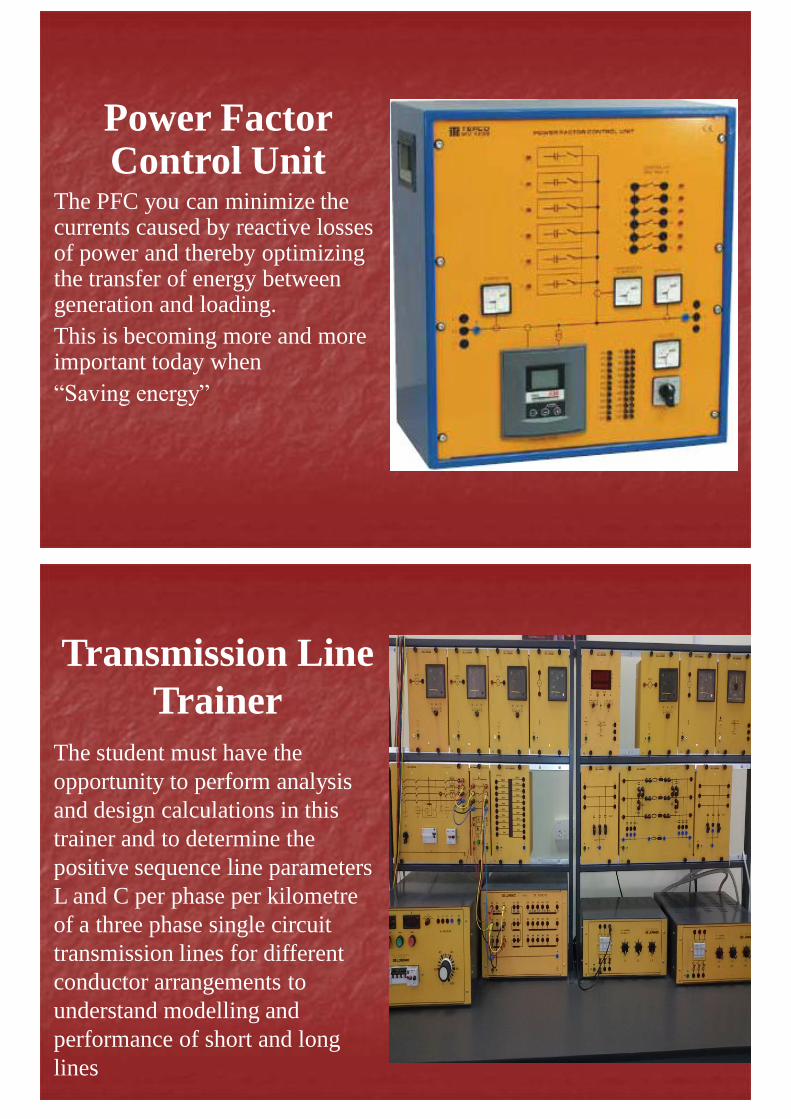
Power Factor Control Unit
The PFC you can minimize the currents caused by reactive losses of power and thereby optimizing the transfer of energy between generation and loading.
This is becoming more and more important today when
“Saving energy”
Transmission Line
Trainer
The student must have the
opportunity to perform analysis
and design calculations in this
trainer and to determine the
positive sequence line parameters
L and C per phase per kilometre
of a three phase single circuit
transmission lines for different
conductor arrangements to
understand modelling and
performance of short and long
lines