dcd-1 data cartridge drive
TRANSCRIPT

· . DATA PRODUCTS ~m
mincom Division ~CDmpANY 3M CENTER • ST. PAUL, MINNESOTA 55101 • (612) 733-8863
DCD-1
INSTRUCTION MANUAL
DATA CARTRIDGE DRIVE
INSTRUCTION MANUAL
LIST PRICE $7.50 C/N 681-3540-9470-8 ISSUE 2

SECTION I.
1·1 1·2 1·3
SECTION II.
2·1 2·2 2-3 2-4 2-5 2-6 2-7 2-8 2-9 2-10
SECTION III.
3-1 3-1·1 3-1-2
3·1-2-1 3-1·2-2 3·1-2-3 3-1-2-4
3-2 3-3
3·3·1
SECTION IV.
TABLE OF CONTENTS
INTRODUCTION
Scope . . . . General Description . Specifications. . . .
GENERAL OPERATING PROCEDURES
Installation Power Application Interface Logic . Interface Signals . . Cartridge Loading Interrecord Gap Timing Writing a Data Block Reading Data. . . . Drive Unit Selection Recommended Maintenance
SUBASSEMBLY DESCRIPTIONS
Mechanical Assembly Description Maintenance . .
Head and Puck Cleaning EOT -BOT Bulb Replacement. . Motor Replacement. . . . . Head Replacement . . . . .
Servo Electronics and READ/WRITE Amplifier PC Assembly Encode/Decode PC Assembly
Description . . . . . . . . . . . . . . .
PARTS LISTS, SCHEMATICS, AND PC BOARD LAYOUTS
APPENDIX
Page
1·1 1·1 1·3
· 2-0 · 2-1
2-1 · 2-1 · 2-8 · 2-8
2-8 2-9
· 2-9 2-9
. . 3-0 · 3-0
3-0 · 3-0
3-0 3-1
· 3·1 3·2 3-9
· 3·9
Page
APPENDIX I. WARRANTY. . . . . . . . . . . . . . . . . . . . . . . Appendix 1-0
© Copyright Minnesota Mining and Manufacturing Company, May 1977
LITHO IN USA WITH 3M BRAND PHOTO OFFSET PLATES

Figure Number
1-1 1-2
2-1 2-2
2-3 24 2-5 2-6 2-7 2-8
3-1 3-2 3-3 34 3-5 3-6 3-7 3-8 3-9 3-10
4-1 4-2 4-3 44 4-5 4-6 4-7
May 1977
LIST OF ILLUSTRATIONS
DCD-l . . . . . Assembly Locations.
Installation Mounting Dimensions for Encode/Decode and Servo Electronics Read/Write
Amplifier PC Assembly . . . . . . . . . . Holes for Flush or Recess Mounting of DCD-l Mechanism Connecting One or More Slave DCD-l Units into a System Interconnecting Cables. " . . . . . Recommended Interface Circuits Block Diagram DCD-l Data Cartridge Drive Magnetic Tape Dimensions
EOT /BOT Bulb Replacement Motor Replacement. . .. . Head Adjustment Screws . . Block Diagram - Drive Logic, Direction Control and Read/Write Amplifier. Block Diagram - Servo Electronics . . . . . . . . . . . . . . . Motion Control R/W Amp Circuit Board, Test Points and Adjustment Potentiometers Block Diagram, Encode/Decode PC Assembly Variable Pulse Width Recording Format . Write Operation Encode Timing Diagram . Read Operation Timing Diagram
Exploded View, Drive Unit, Mechanical Assembly . End Sense Amplifier Board Component Layout Schematic, End Sense Amplifier PC Assembly . . Servo Electronics and Read/Write Amplifier Board Component Layout . Schematic, Servo Electronics and Read/Write Amplifier PC Assembly Encode/Decode Board Component Layout Schematic, Encode/Decode PC Assembly. . . . . . . . . .
ii
Page
1-1 1-2
2-0
2-0 2-1 2-2 2-3 24 2-6 2-6
3-0 3-1 3-2 3-3
. 3-4 3-7 3-8
. 3-9 3-11 3-12
4-1 4-3 4-3 44 4-7 4-8 4-9

Table
2·1 2·2
2·3 24 2·5 2·6
3·1
3·2
3·3
34
3·5
3·6
3·7 3·8 3·9 3·10 3·11
LIST OF TABLES
Page
Active Drive Selection . . . . . . . . . . . . . . . . . . . . . . . 2·5 DCD·l Power Connector Pin Assignments (Servo Electronics and Read/Write
Ampl. PC Assembly) . . • . . . . . . . . . . . .. . . . . . . 2·7 DCD·l Power Connector Pin Assignments (Encode/Decode PC Assembly).. .. 2·7 Interface Connector Pin Assignments . . . . . 2·8 Display Connector Pin Assignments . . . . . . 2·9 Drive Unit Selection . . . . . . . . 2·9
Connector Pin Assignments Servo Electronics and READ/WRITE Amplifier PC Assembly CO 1 Connector. . . . . . . . . . . . . . . .
Connector Pin Assignments Servo Electronics and READ/WRITE Amplifier PC Assembly J 1 A JIB Photocell Connector. . . . . . . . . . .
Connector Pin Assignments Servo Electronics and READ/WRITE Amplifier PC Assembly J2 Head Connector . . . . . . . . . . . . .
Connector Pin Assignments Servo Electronics and READ/WRITE Amplifier PC Assembly J3 Display Connector . . . . . . . . . . . . .
Connector Pin Assignments Servo Electronics and R/W Amplifier PC Assembly J4A J4B Test Point Connector . . . . . . . . . . . . . . . .
Connector Pin Assignments Servo Electronics and R/W Amplifier PC Assembly J 5 Motor Connector . . . . . . . . . . . . .
Interface Pin Assignments C02 on Encode/Decode PC Assembly . Connector Pin Assignments Encode/Decode PC Assembly . .
· 3·6
· 3·6
· 3·6
. . 3·6
. . . 3·7
3·7 3·9 3·10 3·10 Power Connector Pin Assignments Encode/Decode PC Assembly .
Cartridge Capacity as a Function of Data (256 Bytes/Block, 1 Inch IRG) Drive Transfer Rate as a Function of Data (30 ips Tape Speed)
. . .. 3·10 . . 3·10
iii May 1977

NOTES
May 1977 iv

SECTION I. INTRODUCTION
1-1 SCOPE
This manual describes the OCD-l Data Cartridge Drive along with its operation, interface, use, mounting, and maintenance.
Figure 1-1. DCD-l
This manual is divided into 4 sections each of which describes specific aspects of the drive.
SECTION I. INTRODUCTION
This section provides general information and specifications for the drive system as a whole.
SECTION II. GENERAL OPERATING PROCEDURES
This section describes the mounting, interface, use and scheduled maintenance requirements of the OCD-l Cartridge Drive.
SECTION III. SUBASSEMBLY DESCRIPTIONS
This section describes the operation of the various subassemblies which comprise a OCD-I Cartridge Drive.
SECTION IV. PARTS LISTS, SCHEMATICS, AND PC BOARD LAYOUTS
This section contains the engineering documentation for the system.
1-1
1-2 GENERAL DESCRIPTION
The OCD-I Data Cartridge Drive has been designed for use with the "Scotch" Brand OCI00A Data Cartridge. The drive and cartridge provide a tape storage system capable of recording and reading approximately 100,000 eight bit bytes in a physically small, highly reliable unit.
The OCD-l consists of three major subassemblies. These subassemblies are:
1-2-1 MECHANICAL ASSEMBLY
The Mechanical Assembly includes those items necessary to position and hold a cartridge within the drive, to sense the presence of a cartridge within the drive, to detect the position of the cartridge File Protect Slide Switch, and to detect the tape position holes located on the cartridge tape. The mechanical assembly also includes a motor, a tape head, and a light source used in detection of tape position holes.
1-2-2 READ/WRITE AMPLIFIER AND SERVO ELECTRONICS PC ASSEMBLY
This PC Assembly includes the circuitry necessary (1) to maintain tape speed and direction according to input command; (2) to interlock all tape motion commands with tape position status so that improper commands (such as requesting REWIND when tape is at BOT) will not cause activation of the drive motor; (3) to accept TTL Compatible Serial data to be written which places flux transitions on the tape for each change of logic state in the input; and (4) to accept low level read data from the tape head and convert it to a TTL compatible serial data which is identical to the input used when writing data.
This assembly also contains select circuitry which allows up to four units, consisting of a mechanical assembly, read/ write amplifier and servo electronics PC Assembly, to be connected to one Encode/Decode PC Assembly.
1-2-3 ENCODE/DECODE PC ASSEMBLY
This assembly consists of that circuitry necessary to accept 8 bit bytes (bit parallel) as a data input and decode a serial TTL bit stream for use by the write amplifier. This assembly also accepts a serial TTL bit stream from the read amplifier and decodes an 8 bit byte read output for the user.
May 1977

Mechanical Assembly
I nterboard Cable
CA-5 83-0003-0972-0 Customer I nterface Cable
CA-1 83-0003-0968-8 End Sense Cable
Figure 1-2. Assembly Locations
May 1977 1-2
Read/Write Amplifier and Servo Electronics PC Assembly

1-3 SPECIFICATIONS
The specifications of the DCD-l Data Cartridge are as given below:
Cartridge ................................. .
Operating Speeds ............................ .
Tape Head ................................ .
Recording FormatCD ......................... .
Transfer Rate .............................. .
Cartridge Capacity ........................... .
Start Delay. . . . . . . . . . . . . . . . . . . . . . . . . . . . . . . . .
Stop Delay ................................ .
Interface Logic ............................. .
Power ................................... .
Duty Cycle ................................ .
Ambient Temperature ........................ .
Relative Humidity ........................... .
Size .................................... .
Weight ................................... .
Finish ................................... .
NOTES:
CD See Section 3.3.2 for description.
G) PATENT PENDING
1-3
Uses the "Scotch" Brand DCI00A Data Cartridge
FORWARD: 30 ips (76.2 cmps) REVERSE: 30 ips (76.2 cmps) or
60 ips (152.4 cmps)
Single channel, single gap, full width
Variable Cell Width Recording@
2400 bytes/second, average
102,400 bytes, average (256 bytes per block, 1 inch IRG)
27 milliseconds
5 milliseconds
TTL compatible
+5 VDC ±5%, 1.5 amps; +12 VDC (+10.8 VDC to +15 VDC), 1 amp average, 3 amps peak (20 msec duration) while running; 250 rna idle
7 start/stop operations per second maximum
20% to 80%, noncondensing
Drive 5-3/4" wide (14.6 cm) 4" high (10.2 cm) 4-1/2" deep (11.4 cm)
Electronics Two 5" x 12" cards (12.7 x 30.48 cm)
3-1/4 pounds maximum (1.47 kg)
All metal surfaces finished per best commercial practices.
May 1977

SECTION II. GENERAL OPERATING PROCEDURES
Before applying power to or attempting to use the DeD-l, the user should become familiar with this section of the manual.
1 each* Encode/Decode PC Assembly 1 each* Interboard Cable 1 each * Interboard Connector
2-1 INSTALLATION
When unpackaging a DeD-l, the user should insure that the following items were received:
1 each* 6' Interface Cable and Connector Header 3 each * PC Card Pbwer and Display Connectors 2 each** PC Card Power and Display Connectors
leach 1 each
.468-..
1 each Instruction Manual
Mechanical Assembly Read/Write Amplifier and Servo Electronics PC Assembly
* Included with master drive units only ** Included with slave drive units only
.188
1 .... ---4.47---~ 1 ..... 439
~~~~~ltt--·-b ]0 1.11
.587 -rl J25 3.98
l~-~
2.025
L .86 J 3.
84 1 ~o ~~_. 1 --i
1.50 MIN. II.....-_. ____ ~~-----~ 01-------~--
FRONT VIEW TOP VIEW
Figure 2-1. Mounting Dimensions for DCD-! Mechanism
.120 Dia. 4 Holes
Notes: Data Control Board shown. Motion Control/RW Amp Board shown in phantom.
P.C. Board clearances: Allow min. 5/8" component side of P.C. Board. Allow min. 3/8" non-component side.
4.70
4.400
.15 ~ 14------6.307 ~;-d~E·-::5 3-t:·307 II ,-
.15 ~l: -----10.850 • .. f.+.---------------11.15 •
Figure 2-2. Mounting Dimensions for Encode/Decode and Servo Electronics Read/Write Amplifier PC Assembly
May 1977 2-0

-~ I
#632 UNC (6 HOLES)
! ~ • 0 0 1=7 -
.375 ~
I
H t>- O I 3% 2.625
L. .375
H ~ I
I
I· 1.187
~ .... "-~H () - - () ~ ~ - -i.
i Ii .281 ~-~ ~~
I. 5.375 .1 t I I I~. ----5%-----.,.1 Figure 2-3. Holes for Flush or Recess Mounting of DCD-l Mechanism
The OCD-l mechanical assembly may be mounted in any attitude. As shown in Figure 2-1, the unit may be secured at the three ears of the top plate casting. Or if desired, the shipping bracket, used to protect the motor, may be used as a mounting frame. Location of holes for mounting in this frame are shown in Figure 2-1 and 2-2. Note that the top plate casting can be secured to the mounting frame in two different positions as shown in Figure· 2-3. In the forward position, the frame can be attached to a front panel by through-bolting. In the recessed position, the frame can be attached to studs welded to the back of a front panel.
Figure 24 illustrates cable modification procedure for connecting one or more salve units to a master. Electrical interconnection of the three subassemblies is accomplished as shown in Figure 2-5. The two PC Assemblies may be mounted up to 12 inches away from the mechanical assembly. All connectors are keyed to prevent improper interconnection.
2-2 POWER APPLICATION
When applying power to the DCD-l, the + 12 VDC power should be applied prior to application of the +5 VDC power
2-1
input. This prevents any possibility of motor movement during the power up cycle. When removing power, turn off the +5 VDC input first.
2-3 INTERF ACE LOGIC
All inputs and outputs of the DeD-l are TTL compatible with 0 to +0.8 VDC = logic 1 = low and +2.5 VDe to +5.0 VOC = logic 0 = high. The read data output is from 74125 tri-state drivers. The write data input goes directly to 74100 latches. All other outputs are from either 7416 or equivalent open collector buffer drivers. All inputs go to 7404 or equivalent gates. Except for select 0 and 1, which go to a 74155 2 line to 4 line decoder.
Recommended logic interfaces for the DCD-l are as shown in Figure 2-6. When less than 4 feet of cable is used, the 220 ohm/330 ohm resistor terminations may be replaced with lK ohm pull ups if desired.
2-4 INTERF ACE SIGNALS
The interface signals of the OCD-l and their functions are as described below. Details concerning the use of these signals are presented in various sections dealing with specific operations.
May 1977

Surface Insulation
Smooth Side of Cable
Note*
Notch Insulation
Housing
Note*
To connect one or more OCO-1 slave units into a system add connector kit 83-0003-1027-2 to 26 conductor cable as follows:
oeo-, Master Unit
1. At the desired location on the cable where plug is to be added, score the insulation on the shielding side of the cable (smooth side) to enable removal of 3/4" of insulation and shielding. Peel the insulation from the shield, then peel the shield from the cable.
2. Cut sufficient amount of insulation from each side of cable to allow acceptance of the plug to be installed, taking care not to cut into edge conductors.
3. Align plug on the prepared area of the cable, smooth surface to plug connectors.
4. Compress the cable between the plug and the plug plate. (If connector tool is not available for compressing connectors on the cable, a vice may be used.) Top plate should be even with plug tabs when connector is properly seated.
Figure 2-4. Connecting One or More Slave DCD-! Units into a System
May 1977 2-2

26 CIRCUIT CARD EDGE CONNECTOR 3M #3462-0001
/
KEYED BETWEEN CONTACT NO.
COO 4AND6 ~C07
DATA CONTROL LOGIC
J1
1
C01
C02
50
CUSTOMERINTERFACE~ CONNECTOR 50 CIRCUIT CARD EDGE CONNECTOR 3M #3415-0001 KEYED BETWEEN CONTACT NO.8 AND 10 KEY #3439·0000
26 CONDUCTOR FLAT CABLE 3M #3469/26
CA4
INTERCONNECT .J CABLE
C09 C010
<~POWERCONNECTOR~> < 5 CIRCUIT >
< MOLEX #22-01-2051 > TERMINAL
< #08-56-0110 >
< >
50 CONDUCTOR FLAT CABLE 3M #3469/50 (WITH GND. PLANE) 6 FT. LONG
CA5
26
C01
J1A J1B
MOTION CONTROLI RWAMP
J6
J3
2 1
J2
J5
VVVVV C06
DISPLAY OPTION CONNECTOR 5 CIRCUIT MOLEX #22-01-2051
C012 '--______________ ......... ~TERMINAL #08-56-0110
I 50 CIRCUIT SOCKET
C013 I CONNECTOR L-____________ ~ 3M #3425-0000
50 CIRCUIT RIGHT / ANGLE HEADER .---./ 3M # 3433-1 002
C02
END SENSE CABLE 10 CONDUCTOR FLAT CABLE (28 GAUGE)
3M #3365/10 C01 ~ ______________________________________________________________ ~109
CA1
~2~1~~.--------------------10CIRCUITSOCKETCONNECTOR-------------------'.~~2~1 l-l 3M #3473-0000 KEYED ON CONTACT 7 KEY 3M #3435-0000
END SENSE
J1A J1B
HEAD CABLE (CA3) C03
R/W HEAD (REAR VIEW)
4
;> __ ~~ __ ~. ___________ :_~_~ ____________ 7:r-\--~:~~-~-:~[~OOOOO~OOOOO~ ....... I I WHT • I J2 > ~ ~ ~ y 28 AWG 3 CONDo SHIELDED Y ~ >--------..... r LJ DEARBORN 942803 U J4 'l)4 1 3 2
Ls CIRCUIT CONNECTOR HEAD CASE KEYED ON PIN 2 MOLEX #22-01-2051 NORTRONICS SINGLE PIN CONNECTORS TERMINAL #08-56-0110 3M #8127184600 KEY # 15-04-9209
MOTOR CABLE (CA2) MOTOR ASSEMBLY
OJ C04 COS J1
:> r'\ RED .r'\. 2;;. ~ 00000' , > BLK I I 4 > >-1~ _____ --t~ __ ...., / I I I I '7 :> I I CLR I I 3;;. >2~ ___ ..........
~ 22 AWG3CONDUCTOR Lff >4 CABLED, SHI ELDED, >------1-
\ L ALPHA WIRE # 2403 rh L..5 CIRCUIT CONNECTOR KEYED AT POSITION 1
MOLEX #22-01-2051 WITH 08-56-0110 TERMINAL KEY MOLEX # 15-04-9209
4 CI RCUIT CONNECTOR MOLEX #09-50-3041 WITH 08-56-0108 TERMINAL
MOTOR CASE
4 CIRCUIT CONNECTOR MOLEX #09-90-1041
Figure 2·S. Interconnecting Cables
2-3 May 1977

DRIVE USER 74125 74125 or Equivalent
Flat Cable
7404 7404 or Equivalent
NOTE: For short line «4 feet) these lines could be driven from aMOS tri-state driver. Such as is used in some microprocessor systems.
7416 or Equivalent
Flat Cable 7404 or Equivalent
Output From Drive
Flat Cable
7404 or Equivalent
Input to Driver
NOTE: For short lines «4 feet) each line may be pulled up with a single 1 K resistor to +5V and driven by a MaS or standard TTL output. (Remove the 220 - 330 ohm network in tape drive (RN1) and replace with a 1 K network.)
Figure 2-6. Recommended Interface Circuits
24 May 1977

24-1 STATUS OUTPUTS
Two lines which give data relating to tape position and operational status of the drive. These outputs are:
24-1-1 BEGINNING OF TAPE (BOT)
A low level output that occurs when tape is at BOT. A reverse direction motion command will not be accepted when tape is at BOT.
2-4-1-2 READY
An output that is low during read operations when tape is between LOAD POINT and EARLY WARNING. See Figure 2-8. During write operations, the cartridge file protect slide switch must be in the RECORD position and the tape must be between LOAD POINT and EARLY WARNING for READY to go low.
24-2 TAPE MOTION COMMANDS
The DeD-I Data Cartridge Drive has four input lines to control tape motion. These inputs are interlocked to the various drive status and tape position outputs to prevent motions which might damage the cartridge, such as giving a reverse command when the cartridge is already at beginning of tape.
2-4-2-1 FORWARD/REVERSE (F/R)
The status of this line determines the direction of tape motion. A high level causes forward motion and a low level causes reverse motion when the RUN input pulse is applied.
2-4-2-2 RUN
A low going pulse of 500 nanosecond minimum, maximum of 200 microsecond duration on this line causes tape motion to commence in the direction determined by the state of the FORWARD/REVERSE input. Motion com· mences upon the low to high transition.
24-2-3 STOP
A low going pulse on this line of 50 nanosecond minimum duration causes tape motion to stop. The STOP input overrides the RUN input, so that if both RUN and STOP are simultaneously low no tape motion will result.
2-5
24-24 RESET
A low going pulse on this input causes the READY input to go low regardless of tape position. This line is used to clear drive logic after a power interrupt. If tape is in motion when the RESET pulse is applied, tape motion will halt. RESET should be a pulse of 500 nanoseconds minimum duration and should be held low until power is completely up. Note that RESET clears system logic and forces the READY output to the true (low) state. Consequently, improper use of the RESET input (stopping at EOT, apply. ing a reset pulse, commanding forward tape motion, and repeating this sequence) could cause damage to the cartridge. It is therefore recommended that after applying a RESET command, the cartridge be rewound to BOT before commencing further operations.
24·3 SELECT 0 AND SELECT 1
These two lines are used to select the active drive in multiple drive systems according to the following table:
Table 2-1. Active Drive Selection
SELECT 0 SELECT 1 SELECTED DRIVE
High High 0 Low High 1 High Low 2 Low Low 3
244 DATA 0 THROUGH DATA 7
Eight lines which form the data bus (used in both read and write operations). DATA 0 is the least significant bit, DAT A 7 is the most significant bit.
24·5 READ/WRITE CONTROL
A level input which controls mode of operation. This line is held low to perform a write operation (enables head current) and held high to perform a read operation. During write operations, READ/WRITE CONTROL should be set low prior to initiating tape motion and held low until tape motion ceases to insure the writing of clean interrecord gaps.
May 1977

_----. Tape Head
Mechanical Assembly
Inputs & Outputs
"" .. _----Tape Head f.4-
~------ Motor Power
Motor
~-----.
Photocell Assembly
Sensor Outputs
File Protect
t t t +12 Gnd +5
---..---. Power
1 t t t +12 Gnd +5 +12
Motor
t
Motion Control Read/Write Assembly
I I Unit Select
Read RL Bot
(4 Lines)
Motion Write Commands Da1ta (3 Lines)
I
t j I Motion Ready Command Input (4 Lines)
Unit Select (2 Lines)
I
Data Write Cont
Ready Reset
Encode/Decode P.C. Assembly
Select +5VDC Ready
I Incomplete Character
I
File Gnd Protect
-----------.... --~--~-----...... --------Interface Connections -------------Display
Figure 2-7. Block Diagram DCD-l Data Cartridge Drive
C 1102'8 /0023 DIA 111 HDLES)
Trl ..... - ...... -* ~--.. -~ F-.r --- ...
1-2 FTo--L, FTol, FToL2 FTo .1. '40 ;To .1. 2 FTo--L, FTol, FTo--l-2 FToj \ I MINI UM \ I
BOT HOLES LP HOLE EW HOLE EOT HOLES
Figure 2-8. Magnetic Tape Dimensions
May 1977 2-6

2-4-6 READ BUS ENABLE
When this line is pulsed low, the contents of the read buffer are shifted onto the data bus. This pulse also clears the READ BUFFER FULL and INCOMPLETE CHARACTER flags.
The READ BUS ENABLE pulse must be at least 50 nanoseconds in duration and must occur no sooner than 20 nanoseconds after READ BUFFER FULL goes low. The READ BUS ENABLE pulse must return high within 200 microseconds of READ BUFFER FULL going low to avoid missing data.
2-4-7 INTERRECORD GAP
An output that goes low each time an interrecord gap is detected. This output is active when tape is moving in either the forward or reverse direction.
2-4-8 WRITE BUFFER EMPTY
This is an output flag that goes low to indicate that the write buffer is empty and ready to accept another byte of data.
When the first byte of a block is loaded, WRITE BUFFER EMPTY will go low again within from 16.7 microseconds to 83.5 microseconds, depending upon internal logic timing. After going low for the second byte, WRITE BUFFER EMPTY will go low no sooner than every 350 microseconds.
2-4-9 LOAD WRITE BUFFER
A low going pulse on this input causes information on the data bus to be strobed into the write buffer. This pulse must be at least 500 nanoseconds but no greater than 1.5 microseconds long. (The LOAD WRITE BUFFER pulse must occur less than 320 microseconds after WRITE BUFFER EMPTY goes low.) The LOAD WRITE BUFFER pulse also clears the WRITE BUFFER EMPTY output flag.
2-4-10 READ BUFFER FULL
This is an output flag that goes low when the read buffer contains a data byte. This flag will stay low until cleared by a READ BUS ENABLE input flag. READ BUFFER FULL will go true no sooner than every 200 microseconds.
2-7
In order to discriminate against false transitions in the interrecord gap, one 8 bit byte must be read before this flag becomes active.
2-4-11 INCOMPLETE CHARACTER
This is an output flag that goes low if a complete 8 bit byte is not contained in the read buffer when the READ BUFFER FULL output goes low. All bytes containing fewer than 8 bits will result in this flag going low thus indicating an error condition caused typically by tape dropouts. In order to discriminate against false transitions in the interrecord gap, one 8 bit byte must be read before this flag becomes active. A READ BUS ENABLE pulse clears this flag; therefore the status of this flag should be checked after READ BUFFER FULL goes low but before the READ BUS ENABLE input is issued.
Table 2-2. DCD-l Power Connector Pin Assignments (SERVO ELECTRONICS AND READ/WRITE AMPL
PC ASSEMBLy)
Pin
2 3 4 5
Function
+12 VDC 10.8 VDC to 15.0 VDC, 1 Amp Avg.3 Amps Peak (20 msec duration) while running; 250 rna idle Ground +5 VDC ±5%, 0.5 amps Ground +12 VDC
Table 2-3. DCD-l Power Connector Pin Assignments (ENCODE/DECODE PC ASSEMBLy)
Pin
1 2 3 4 5
Function
+ 12 VDC (Not Used) Ground +5 VDC ±5% 1.5 Amps Ground + 12 VDC (Not Used)
Logic interface connection to the DCD-1 is via a 50 pin, PC card edge connector, "Scotchflex" No. 3415-0001 or equivalent, keyed between contacts 8 and 10. For "Scotchflex" connectors, use key No. 3439-0000.
Power connection is via two Molex connectors, No. 22-01-2051 with contacts No. 08-56-0114. One connector is used for each PC card.
May 1977

Table 24. Interface Connector Pin Assignments
Function Pin
Run 2 Load Write Buffer 4 Select 0 6 Select 1 8 Read/Write Control 10 Forward/Reverse 12 Reset 14 Stop 16 Read Bus Enable 18 Ready 20 Write Buffer Empty 22 Interrecord Gap 24 Incomplete Character 26 Read Buffer Full 28 Beginning of Tape 30 Not Used 32 Not Used 34 Data 0 36 Data 1 38 Data 5 40 Data 4 42 Data 2 44 Data 3 46 Data 7 48 Data 6 50 Common All Odd No. Pins 149
2-5 CARTRIDGE LOADING
Loading the cartridge requires inserting a cartridge into the drive and positioning tape at Load Point.
The cartridge is installed in the drive by inserting it into the rectangular slot in the drive facade. With respect to the top plate, the cartridge is inserted with its metal base plate next to the drive top plate and with the cartridge edge containing head door and belt capstan being inserted first (this is the only cartridge orientation that will permit cartridge loading). The cartridge should be pushed fully into the drive; an audible click will be heard and the EJECT button protrudes from the front of the mechanism when the cartridge is engaged by the drive. Should difficulty be encountered, be sure the EJECT button is fully depressed before inserting the cartridge. To remove a cartridge from the drive, depress the EJECT button on the front facade of the drive.
Once the cartridge has been inserted into the drive, the l1rst command issued must be for reverse motion (this is the
May 1977 2-8
only command that will be accepted until BOT is reached). When tape motion stops at BOT, command forward motion until Load Point is reached (the READY output will go true). The drive and cartridge are now initialized and ready for subsequent read/write operations.
It is recommended that an initial gap of 7-1/2 inches or longer be used between the LOAD POINT hole and the first data record. (Approximately 275 ms delay following the READY signal at LOAD POINT will produce this initial gap.)
2-6 INTERRECORD GAP TIMING
To insure the writing of proper length interrecord gaps, the following delays should be employed:
(a) After commanding forward tape movement, delay 27 milliseconds before entering the first data byte.
(b) After writing (or reading) the last data byte, delay 5 milliseconds before commanding a STOP. During read operations, the INTERRECORD GAP output indicates the end of a data block.
2-7 WRITING A DATA BLOCK
When writing data, the following sequence of events should be used:
1. Set the READ/WRITE CONTROL input to the low logic state.
2. Check the READY output (assuming that tape is between LOAD POINT and EARLY WARNING). If it is low, proceed. If it is high, remove the cartridge, place the fIle protect slide switch in the RECORD position, reinsert the cartridge, set READ/WRITE CONTROL high, rewind to BOT, come forward until READY goes low, stop tape motion, and commence operation again at Step 1.
3. Set the FORWARD/REVERSE input high.
4. Apply a pulse to the RUN input.
5. Delay 27 milliseconds during which time the first byte to be written should be placed on the data bus.
6. After 27 milliseconds apply a LOAD WRITE BUFFER pulse.
7. Monitor the WRITE BUFFER EMPTY output. When this output goes true place the next byte to be writ-

ten on the data bus and issue another LOAD WRITE BUFFER pulse. Continue this process until all required bytes have been written.
8. Five milliseconds after the last LOAD WRITE BUFFER input, apply a STOP pulse.
9. Allow 20 milliseconds for tape motion to stop.
10. If the next operation to be performed is a write, leave READ/WRITE CONTROL low. If a read or rewind is to be performed next, set READ/WRITE CONTROL high.
2-8 READING DATA
The reading of data is accomplished per the following procedure:
1. Set the FORWARD/REVERSE input high.
2. Apply a pulse to the RUN input.
3. Apply a pulse to the READ BUS ENABLE input to clear the READ BUFFER FULL and INCOMPLETE CHARACTER flag circuits. This pulse should occur within 20 microseconds of the RUN pulse.
4. Monitor the READ BUFFER FULL output. For the first byte, it will go low about 27 milliseconds after the RUN pulse is applied. Thereafter it will go true approximately every 350 microseconds.
S. When READ BUFFER FULL goes low check the level of the INCOMPLETE CHARACTER output to determine if an error has occurred.
6. Set the READ BUS ENABLE input low. The data byte will have settled on the data bus within SO nanoseconds of this input. Read data is only on the bus as long as this input is low.
7. After the byte has been captured by the user's circuitry, set READ BUS ENABLE high.
8. Alternate between monitoring the READ BUFFER FULL and INTERRECORD GAP flags.
9. If READ BUFFER FULL goes low, return to Step S.
10. If INTERRECORD GAP goes low, wait 5 milliseconds and apply a pulse to the STOP input. Wait 20 milliseconds for tape motion to stop before issuing further commands. A continuous read is accomplished by not issuing the STOP pulse.
2-9
Table 2-5. Display Connector Pin Assignments
FUNCTION
Select +5 VDC File Protect Ground Ready
SYMBOL USED ON SCHEMATIC
SEL +SVDC FP GND RDY
2-9 DRIVE UNIT SELECTION
PIN
1 2 3 4 5
As noted in paragraph 1-2-2, the DCD-l is available in multiple drive configurations. When 2 or more drives are present, the SELECT a and SELECT 1 inputs must be used to determine which drive shall be operative during execution of a given function. Selection is accomplished according to the following table:
Table 2-6. Drive Unit Selection
DRIVE
a 1 2 3
SELECT a
High Low High Low
2-10 RECOMMENDED MAINTENANCE
SELECT 1
High High Low Low
The only periodic maintenance required on the DCD-l is cleaning of the tape head and motor drive roller.
These items should be cleaned with ethyl alcohol and a cotton swab every 1,000 to 1,500 cartridge cycles. A cycle is defined as tape movement from BOT to EOT and back to BOT.
In harsh environments cleaning may be required more frequently.
May 1977

SECTION III. SUBASSEMBLY DESCRIPTIONS
3-1 MECHANICAL ASSEMBLY
3-1-1 DESCRIPTION
The Mechanical Assembly consists of those items necessary to position and hold a cartridge for READ/WRITE OPERATION, to apply rotary power to the cartridge bolt capstan to create motion, to detect the presence of a cartridge within a drive, to determine the status of the cartridge me protect plug, and to detect the tape position holes of the cartridge.
The major components of the assembly are the top plate, the motor-tachometer, the tape head, and the photocell amplifier PC Assembly.
3-1-2 MAINTENANCE
3-1-2-1 HEAD AND PUCK CLEANING
The only periodic maintenance required on the mechanical assembly is cleaning of the tape head and the drive puck. This cleaning operation should be accomplished every 1,000 - 1,500 tape cycles. In harsh environments, cleaning on a more frequent basis may be required.
Cleaning should be accomplished with a cotton swab moistened with ethyl alcohol by gently rubbing the head and then the drive puck.
Left Rail Mounting Screw
Sensing Switch Left Rail Mounting Screws Mounting Screw
NOTE
The useful life of the DCD-I Data Cartridge Drive is estimated at 40,000 tape cycles. At this point, the head and/or motor may be near failure, and the user may elect to change these components.
It is recommended, however, that only the volume user with formalized depot programs and facilities attempt to replace these components in the Mechanical Assembly. Other users are advised to return the unit to the factory for replacement of these items.
Replacement of the EOT /BOT bulb is the one procedure which does not require specialized tools and fixtures.
3-1-2-2 EOT-BOT BULB REPLACEMENT
1. Remove the two front bezel mounting screws.
2. Remove the front bezel.
3. Unplug the cable from the EOT/BOT PC Board.
4. Remove the two rail mounting screws (left rail).
EDT/BOT PC Assembly
EDT/BOT Bulb Photo Transistors
Front Bezel Mounting Screws
Figure 3- t. EOT /BOT Bulb Replacement
May 1977 3-0

5. Remove the left rail and the EOT /BOT PC Assembly from the mechanism.
6. Remove the two sensing switch mounting screws.
CAUTION
Hex nuts are free in block depression.
7. Remove Phillips mounting screw and plastic insulation washer from the EOT /BOT PC Assembly.
8. Remove the EOT/BOT PC Board and switch assembly from the block.
9. Unsolder the old bulb from the board and clean the solder from the holes.
10. Place the new bulb leads through the holes and insert the bulb fully into the block as the PC board is again fitted to the block. Secure with the Phillips mounting screw and insulating washer.
11. Solder bulb leads with the bulb located all the way into the block.
12. Reverse the disassembly procedure from Step 6 through Step 1.
3-1-2-3 MOTOR REPLACEMENT See Figure 3-2
1. Remove the deck from the mounting base.
2. Remove the power cable from the motor.
3. Remove the two motor pivot mounting screws.
4. Remove the motor assembly. Retain the pivot pins.
5. Insert the pivot pins into the new motor mounting.
6. Remount the motor using the screws and pivot hold down clamps.
7. No end play is permissible in the motor pivot mount. Secure one pivot clamp and force the other pivot pin into the motor mount, tighten the second pivot clamp. If end play is not completely removed, loosen one pivot clamp and force the pivot pin in, then retighten the clamp screw.
3-1
See maintenance section for motor control alignment procedure.
8. Whenever a motor is replaced the Servo Electronics MUST BE REBALANCED.
Mounting Screws
Pivot Clamp
V ~tor I/~V~
-__"'\\\\1..< /'
Power Cable
.~ Motor Assembly I
i
I 1
Figure 3-2. Motor Replacement
3-1-2-4 HEAD REPLACEMENT See Figure 3-3
1. Loosen the head clamp screw sufficiently to allow the head to be removed.
2. Be sure the new head has one wrap of mylar tape around the body of the head to give insulation between head and the mounting bracket.
May 1977

3. Slide the new head into place and tighten the mounting screw lightly so that head position can be changed with finger pressure.
4. Position the head so that the head will push the tape . 055" to .065" into the cartridge when a cartridge is inserted fully into the deck. This may be done by measuring the distance from when the head first contacts the tape as a cartridge is inserted, and when the cartridge is firmly in position.
5. Align the two mating surfaces of the head clamp and tighten the head clamp firmly.
6. Install an azimuth alignment cartridge into the drive and adjust the azimuth screw for maximum output at TP3.
Azimuth Adjusting Screw
Do not adjust or remove
.055 to .065 Penetration into Cartridge
Figure 3-3. Head Adjustment Screws
3-2 SERVO ELECTRONICS AND READ/WRITE AMPLIFIER PC ASSEMBLY
This assembly is comprised of the major sub functions listed below. See Block Diagrams, Figure 3-4 and 3-5.
May 1977 3-2
3-2-1 DRIVE SELECT LOGIC
This circuitry consists of the select jumper plug which enables only the selected drive command input gates and output gates .
3-2-2 DIRECTION CONTROL LOGIC
This circuitry is comprised of two sections.
1. The Status Logic section monitors cartridge related factors such as tape position, file protect status, and cartridge in place status.
2. The Command-Status Interlock section prevents acceptance of motion commands which could harm the cartridge (rewinding from BOT, etc.).
3-2-3 SERVO ELECTRONICS
This circuitry consists of several sections which operate in unison to control the direction and speed of tape motion (by controlling motor input voltage).
3-2-4 WRITE CIRCUITRY
This circuitry consists of a write enable transistor switch which only permits head current to flow when the READ/ WRITE Control input is low, and the write head drivers.
3-2-5 READ CIRCUITRY
This circuitry consists of Operational Amplifiers for Read, Threshold Detector, and Peak Detector.
3-2-6 DRIVE SELECT LOGIC See Figures 3-4 and 3-5
One of four ENABLE inputs is connected through a jumper plug at connector J8 to ICI6, pin 9. This signal is routed through 2 inverter stages and then enables negative and gates for input signals (RUN, STOP, READ/WRITE CONTROL, WRITE DATA, FORWARD/REVERSE, and RESET). The same signal also enables tri-state gates for output signals (BOT, READY, and READ DATA). The signal at ICI6, pin 8 is also inverted to provide a SELECT output at IC20, pin 2. This output can sink 40 rna at +5 VDC.

3-2-6-1 LOGIC INTERFACE CONNECTIONS
The interface connections of the drive select logic portion of the read/write amplifier and servo electronics PC Assembly and their use is as described below:
3-2-6-2 ENABLE 0, 1, 2 AND 3
One to four drives may be used in a system. Selection of one of four drives is performed on the data control logic PC
Electronic Assembly. This will hold either EN 0, EN 1, EN 2, or EN 3 to ground and thereby selects the proper drive.
3-2-6-3 UNIT DESIGNATE
J8 requires a jumper plug to select the proper drive. Place the jumper plug in the ° position when only one drive is used. When multiple drives are used designate the drive number by placing the jumper plug in positions 0, 1, 2, or 3.
From Mechanical Assembly -------------WP CT HD HD
RWC
STP
RUN
WD
FIR
EN 0
EN 1
EN 2
EN 3
RST
I~ From I!£.!. Mech < Assembly C IN
FP
t
Drive Select Logic
Status Decode Logic
BOT ROY RD Drive Select Logic
! ! ! BOT ROY RD
RWC
WD
-
Command Status Interlock
!£!1 PC2
CIN
! Write Enable
WE
Write Head Driver
FWD
REV
HD
HD
---.,.-'
To Servo Electronics
Read Amplifier
RD
Threshold Detector
Peak Detector
Figure 34. Block Diagram - Drive Logic, Direction Control and Read/Write Amplifier
3-3 May 1977

3-2-64 FORWARD/REVERSE
The status of this line detennines the direction of the tape motion. A high level causes forward motion while a low causes a reverse motion when the RUN input pulse is applied.
3-2-6-5 RUN
A low going pulse on this line of 500 nanosecond minimum duration causes tape motion to commence in the direction detennined by the status of the command input. Motion commences upon the low to high transition.
3-2-6-6 STOP
A low going pulse of 500 nanosecond minimum, maximum of 200 microsecond duration on this line causes tape motion to commence in the direction determined by the state of the FORWARD/REVERSE input. Motion commences upon the low to high transition.
3-2-7 STATUS DECODE LOGIC
3-2-7-1 CARTRIDGE IN (CIN)
A switch on the mechanical assembly senses the presence of the data cartridge. When the cartridge is out this line clears the 4 bit bidirectional shift register (IC3) and sets the set/reset flip flop (IC 1 0) to the initialization state.
-Error
~ Amplifier
Forward ~
Reference Reverse Amplifier ~
4~ Error + Amplifier
3-2-7-2 PHOTOCELL 1 (PC1)
An input from the Photocell Amplifier PC Assembly. Momentarily high when a hole passes by the Photosensor. Used along with Photocell 2 to develop the various tape position outputs. A hole in the tape passes by Photocell 1 before Photocell 2 when the tape is moving in the forward direction.
3-2-7-3 PHOTOCELL 2 (PC2)
An input from the Photocell Amplifier PC Assembly. Momentarily high when a hole passes by the Photosensor. Used with Photocell 1 to develop the various tape position outputs.
3-2-74 FILE PROTECT
An input from the file protect switch of the photocell amplifier PC Assembly. During write operations the file protect switch on the DC 100A Cartridge must be in the record position. If it is not in the Record position and RWC (Read/Write Control) is forced true, RDY will go false indicating the drive is not in the proper mode for writing. Forward and reverse motion can still take place with RDY false, but no writing will occur since the write current is disabled whenever the record switch on the DCIOOA is not in the record position.
Automatic Switch Select
Driver 1
I Bridge
I Driver 2
Back EMF Amplifier
~ --
I.....-
Switch 2
f To Mota Mechanic Assembl
r al
y
Switch 1
Figure 3-5. Block Diagram - Servo Electronics
May 1977 3-4
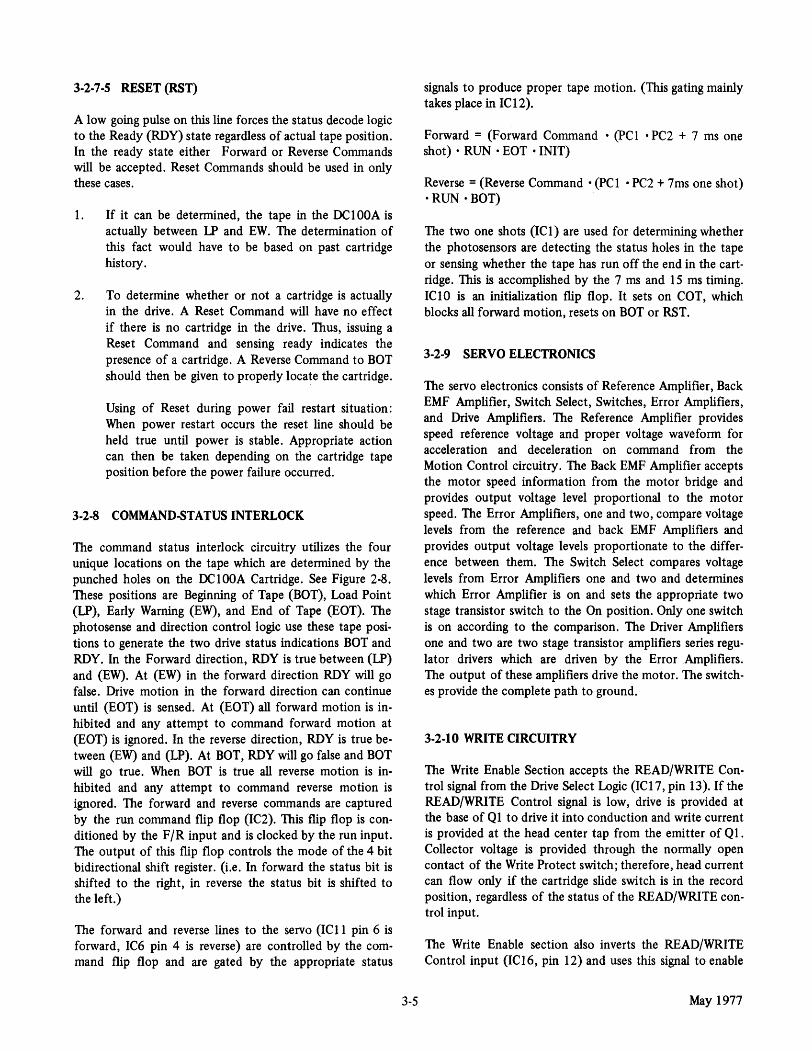
3-2-7-5 RESET (RST)
A low going pulse on this line forces the status decode logic to the Ready (RDY) state regardless of actual tape position. In the ready state either Forward or Reverse Commands will be accepted. Reset Commands should be used in only these cases.
1. If it can be determined, the tape in the DCI00A is actually between lP and EW. The determination of this fact would have to be based on past cartridge history.
2. To determine whether or not a cartridge is actually in the drive. A Reset Command will have no effect if there is no cartridge in the drive. Thus, issuing a Reset Command and sensing ready indicates the presence of a cartridge. A Reverse Command to BOT should then be given to properly locate the cartridge.
Using of Reset during power fail restart situation: When power restart occurs the reset line should be held true until power is stable. Appropriate action can then be taken depending on the cartridge tape position before the power failure occurred.
3-2-8 COMMAND-STATUS INTERLOCK
The command status interlock circuitry utilizes the four unique locations on the tape which are determined by the punched holes on the OCI00A Cartridge. See Figure 2-8. These positions are Beginning of Tape (BOT), Load Point (LP), Early Warning (EW), and End of Tape (EOT). The photosense and direction control logic use these tape positions to generate the two drive status indications BOT and RDY. In the Forward direction, RDY is true between (lP) and (EW). At (EW) in the forward direction RDY will go false. Drive motion in the forward direction can continue until (EOT) is sensed. At (EOT) all forward motion is inhibited and any attempt to command forward motion at (EOT) is ignored. In the reverse direction, RDY is true between (EW) and (lP). At BOT, RDY will go false and BOT will go true. When BOT is true all reverse motion is inhibited and any attempt to command reverse motion is ignored. The forward and reverse commands are captured by the run command flip flop (lC2). This flip flop is conditioned by the F /R input and is clocked by the run input. The output of this flip flop controls the mode of the 4 bit bidirectional shift register. (Le. In forward the status bit is shifted to the right, in reverse the status bit is shifted to the left.)
The forward and reverse lines to the servo (IC 11 pin 6 is forward, lC6 pin 4 is reverse) are controlled by the command flip flop and are gated by the appropriate status
3-5
signals to produce proper tape motion. (This gating mainly takes place in ICI2).
Forward = (Forward Command • (pCI • PC2 + 7 ms one shot) • RUN • EOT • INIT)
Reverse = (Reverse Command • (pC I • PC2 + 7ms one shot) • RUN· BOT)
The two one shots (lCl) are used for determining whether the photosensors are detecting the status holes in the tape or sensing whether the tape has run off the end in the cartridge. This is accomplished by the 7 ms and 15 ms timing. ICI0 is an initialization flip flop. It sets on COT, which blocks all forward motion, resets on BOT or RST.
3-2-9 SERVO ELECTRONICS
The servo electronics consists of Reference Amplifier, Back EMF Amplifier, Switch Select, Switches, Error Amplifiers, and Drive Amplifiers. The Reference Amplifier provides speed reference voltage and proper voltage waveform for acceleration and deceleration on command from the Motion Control circuitry. The Back EMF Amplifier accepts the motor speed information from the motor bridge and provides output voltage level proportional to the motor speed. The Error Amplifiers, one and two, compare voltage levels from the reference and back EMF Amplifiers and provides output voltage levels proportionate to the difference between them. The Switch Select compares voltage levels from Error Amplifiers one and two and determines which Error Amplifier is on and sets the appropriate two stage transistor switch to the On position. Only one switch is on according to the comparison. The Driver Amplifiers one and two are two stage transistor amplifiers series regulator drivers which are driven by the Error Amplifiers. The output of these amplifiers drive the motor. The switches provide the complete path to ground.
3-2-10 WRITE CIRCUITRY
The Write Enable Section accepts the READ/WRITE Control signal from the Drive Select Logic (lC 17, pin 13). If the READ/WRITE Control signal is low, drive is provided at the base of Ql to drive it into conduction and write current is provided at the head center tap from the emitter of Ql. Collector voltage is provided through the normally open contact of the Write Protect switch; therefore, head current can flow only if the cartridge slide switch is in the record position, regardless of the status of the READ/WRITE control input.
The Write Enable section also inverts the READ/WRITE Control input (ICI6, pin 12) and uses this signal to enable
May 1977

the READ DATA output (IC 13, pin 6) only if the READ/ WRITE Control input is high.
The Write Head Driver section consists of two "AND" gates, which are enabled if the write mode is selected.
One gate is provided with the WRITE DATA and the other with WRITE DATA. The output of those two gates (ICll, pin 11, ICll, pin 3) are then routed to the open collector drivers (lC 1 7, pin 9 and pin 11) which drive the tape head.
3-2-11 READ CIRCUITRY
The Read Amplifier section accepts the low level read data from the tape head and amplifies this signal to a nominal 2.0 V pop level (ICI8, pin 6).
This amplified data is then clipped at a 28 percent level by the threshold detector (lCI9, pin 14) to remove any background noise from the signal.
The peak detector senses peaks in the amplified signal and produces a TTL compatible reproduction of the data (lC 19, pin 1).
Table 3-1. Connector Pin Assignments Servo Electronics and READ/WRITE
Amplifier PC Assembly CO 1 Connector
ABBREVIATION USED ON
SIGNAL SCHEMATIC PIN
Beginning of Tape BOT 1 Ready RDY 3 Read Data RD 5 Run Run 7 Stop STP 9 Read/Write Control RWC 11 Write Data WD 13 Forward/Reverse F/R 15 Reset RST 17 Enable Drive 0 ENO 19 Enable Drive 1 ENI 21 Enable Drive 2 EN2 23 Enable Drive 3 EN3 25 Ground GND 2-26
May 1977 3-6
Table 3-2. Connector Pin Assignments Servo Electronics and READ/WRITE
Amplifier PC Assembly JIA JIB Photocell Connector
ABBREVIATION USED ON
SIGNAL SCHEMATIC
Photoce112 PC2 Photocell 1 PCl Cartridge IN CIN File Protect FP Ground GND + 12V Endsense +12V Key Key +5V +5V Write Protect WP Cartridge COT
Table 3-3. Connector Pin Assignments Servo Electronics and READ/WRITE
Amplifier PC Assembly J2 Head Connector
ABBREVIATION USED ON
SIGNAL SCHEMATIC
Center Tap CT Head HD Head HD Shield SHLD Key Key
Table 34. Connector Pin Assignments Servo Electronics and READ/WRITE
Amplifier PC Assembly J3 Display Connector
ABBREVIATION USED ON
SIGNAL SCHEMATIC
Select Select +5VDC +5VDC File Protect File Protect Ground GND Ready Ready
PIN
2 4 3 5 1 9 7 6
10 8
PIN
3 5 1 4 2
PIN
2 3 4 5

Table 3-5. Connector Pin Assignments Servo FJectronics and R/W Amplifier PC Assembly
J4A J4B Test Point Connector
SIGNAL
Ground Reference Amp Output Read Amp Output Back EMF Amp Output Fwd Driver Amp Output Rev. Driver Amp Output Motor Bridge Output Motor Bridge Output
ABBREVIATION USED ON SCHEMATIC PIN
TPI 1 TP2 2 TP3 3 TP4 4 TP5 5 TP6 6 TP7 7 TP8 8
Table 3-6. Connector Pin Assignments Servo Electronics and R/W Amplifier PC Assembly
J 5 Motor Connector
ABBREVIATION USED ON
SIGNAL SCHEMATIC PIN
Motor Motor Shield Sensing Coil Key
3-2-12 MAINTENANCE See Figure 3-6
MTR MTR SHLD SENS Key
3-2-12-1 Motor Control Alignment Procedure Motor Balance Adjustment
4 5 2 3 1
(a) Connect Motor cable to motor and motion control PC Board connector (15).
(b) The following test fixture should be constructed to properly balance the Servo Bridge.
(c) The motor must be locked while balancing the Servo Bridge. This may be accomplished by inserting a cartridge into the deck.
(d) With the test flXture applied to test points adjust R71 balance pot to obtain zero volts on the VTVM readout (±0.5 mv should be easily achieved). Rotate the motor shaft to insure balance is not at high resistance point.
*Either of two types of Drive motors may be used on this drive. Measure the dc resistance of the motor to determine the correct parallel resistor. Measure between TP6 and TP7. For Motors having 3.6 ohms dc resistance use 120 ohms 1/4w resistor. For Motors having 2.4 ohms dc resistance use a 80 ohm resistor to achieve proper balance.
The Servo Null Pot (R69) and the Motor Speed Adjust Pot (R70) will require adjusting whenever components are changed in the Reference or Back EMF Amplifiers. Whenever these adjustments are made, they should be made after the motor balance adjustment has been made.
Reference Amplifier Null Adjust
1. Connect a VTVM or digital voltmeter between test points TP2 and TP4, at J4 on the motion control board.
2. Adjust R69 for zero volts (±5 mv) while the servo system is operational. Whenever the Null R69 is adjusted, the speed adjustment should be checked.
The speed of the motor may be measured by using a 1600 frpi calibration test tape and a counter. Adjust R70 to give 24 kHz at pin 5 on the COl connector. Another method is to use a stop watch to time the length of the READY status output, while running a cartridge from BOT to EOT. 56 seconds is the proper time interval.
5::~~c~~~~~~-o-n-1w-_-_-_-~~~~~~l---;llt--l-* ;;,.-------8 I I I I I I I I ~ ~ R71
I TP 1 2 3 4 5 6 7 8 I I : I ! 0 J4 A,B L_J L_..J
Figure 3-6. Motion Control R/W Amp Circuit Board, Test Points and Adjustment Potentiometers
3-7 May 1977

v.J 00
To/From Servo Electronics & ReadlWrite Amplifier PC Assembly
R D
ead ata
Clock
..... Shift Pulse (1 Per Bit)
Read Data Synchronizer
Up
Clock Divide Down
Clear Serial to Read Decode Parallel (Up-Down Converter Counter) &
Buffer
(7.665 Mhz) (6.132 Mhz Out) Decoded Data
Encode Clock Load Buffer t
Generator (+128)
I ntercharacter Gap
(Flag Clear)
Shift Pulse Error Check
Interrecord Gap Count
Write Encoded Write Data Data Encode Serial Data
~ Start
Encode Parallel Shift Stop Timing to Serial Control Converter
Character Present
(Clear)
Write Flag t Logic
Figure 3-7. Block Diagram, Encode/Decode PC Assembly
f----+ r---+ r---+ r---+ f----+ ~
~
t---+-
Data Output Buffer & Gates
j
~
~J
~! )
f---+-( f---+-
f---+-~
Read Data Output
Gate Enable
(Clear)
R E
ead Bus nable
Read Flag ~R F ead Buffer ull Logic
I ncomplete Character
8 Count
~ (Clear) IRG Flag Logic
~
-----~
~
~
~
f---+-I nterrecord Gap
) , }
I
1 I
Write Data Input
L oad Write Buffer
Write Buffer Empty
To/From User's Logic

Table 3-7. Interface Pin Assignments C02 on Encode/Decode PC Assembly
SYMBOL USED FUNCTION ON SCHEMATIC PIN
Data 0 DATA 0 36 Data 1 DATAl 38 Data 2 DATA 2 44 Data 3 DATA 3 46 Data 4 DATA 4 42 Data 5 DATA 5 40 Data 6 DATA 6 50 Data 7 DATA 7 48 Read Bus Enable RDBEN 18 Interrecord Gap IRG 24 Write Buffer Enable WBE 22 Load Write Buffer LWRTE 4 Read Buffer Full RBF 28 Incomplete Character ICC 26 Ready RDY 20 Beginning of Tape BOT 30 Reset RST 14 Forward/Reverse F/R 12 Run RUN 2 Stop STP 16 Read Write Control RWC 10 Select 0 SEL-O 6 Select 1 SEL-l 8
3-3 ENCODE/DECODE PC ASSEMBLY
3-3-1 DESCRIPTION See Figure 3-7
The Encode/Decode PC Assembly provides a serial byte oriented (eight bit parallel) data interface for the user. During write operations the assembly accepts bytes to be written and converts these bytes to a serial bit stream in Variable Cell Width format (described in paragraph 3-3-2) for use by the Read/Write Amplifier PC Assembly.
During read operations, the assembly accepts data from the Read/Write Amplifier PC Assembly in a TTL compatible, Variable Cell Width format and decodes this information into an eight bit byte (high for a "Zero", low for a "One") for output to the user.
Further, the assembly contains an Interrecord Gap Detector and Error Detector with associated output flags.
Also, the assembly contains a Select Decode function which allows one Encode/Decode Assembly to operate with up to
3-9
four Read/Write Amplifier Assemblies. The assembly also contains 220/330 ohm input line terminators and line drivers for all user input/output signals. See Figure 2-6.
3-3-2 VARIABLE CELL WIDTH RECORDING
Variable cell width recording derives its name from the fact that a given bit cell varies in width according to whether a "1" or a "0" is being recorded. As shown in Figure 3-8, a bit cell consists of two pulses, a timing pulse of length t followed by a data pulse of length t if the bit is a "0" or length 2t if the bit is a "1".
I 1 111010101 110101
--11 I.-OATA PULSE ~ ~TIMING PULSE
I 0 I 1 I
I- BYTE 1 _14 ICG.f..BYTE 2~
Figure 3-8. Variable Pulse Width Recording Format
When writing data, the length of the timing and data pulses is derived from a crystal oscillator. Implementation of the read decode function is as follows:
1. When the first transition of the timing pulse occurs, a counter is cleared and begins counting in a positive direction at frequency f (7.665 mHz).
2. At the next transition, which ends the timing pulse, the counter begins counting in a negative direction at frequency 0.8f (6.132 mHz).
3. At the final transition of the bit cell, the counter contents are sampled. Since counting in the negative direction is accomplished at a lower frequency when counting up, the counter will contain a positive number if the recorded bit was a "0" and a negative number if the recorded bit was a "I".
This encode/decode technique can tolerate a total speed variation of ±20% in the drive mechanism without causing subsequent read errors or impairing the ability to interchange data between drives.
As shown in Figure 3-8, each stream of recorded data ends with a timing pulse so that this encode/decode technique may permit read reverse operation. Although read reverse is
May 1977
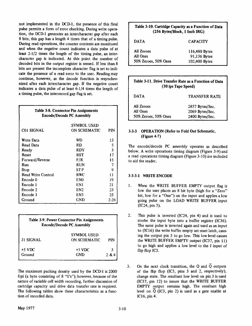
not implemented in the DCD-l, the presence of this final pulse permits a form of error checking. During write opera· tion, the DCD-l generates an intercharacter gap after each 8 bits; this gap has a length 4 times that of a timing pulse. During read operations, the counter contents are monitored and when the negative count indicates a data pulse of at least 2-1/2 times the length of the timing pulse, an inter· character gap is indicated. At this point the number of decoded bits in the output register is sensed. If less than 8 bits are present the incomplete character flag is set to indio cate the presence of a read error to the user. Reading may continue, however, as the decode function is resynchro· nized after each intercharacter gap. If the negative count indicates a data pulse of at least 6-1/4 times the length of a timing pulse, the interrecord gap flag is set.
Table 3-S. Connector Pin Assignments Encode/Decode PC Assembly
SYMBOL USED COl SIGNAL ON SCHEMATIC
Write Data WD Read Data RD Ready ROY Reset RST Forward/Reverse F/R Run RUN Stop STP Read Write Control RWC Encode 0 ENO Encode 1 ENI Encode 2 EN2 Encode 3 EN3 Ground GND
Table 3-9. Power Connector Pin Assignments Encode/Decode PC Assembly
11 SIGNAL
+5VDC Ground
SYMBOL USED ON SCHEMATIC
+5VDC GND
PIN
13 5 3
17 15
7 9
11 19 21 23 25
2-26
PIN
3 2 &4
The maximum packing density used by the DCD-l is 2000 frpi (a byte consisting of 8 "O's"); however, because of the nature of variable cell width recording, further discussion of cartridge capacity and drive data transfer rate is required. The following tables show these characteristics as a func· tion of recorded data.
May 1977 3-10
Table 3-10. Cartridge Capacity as a Function of Data (256 Bytes/Block, 1 Inch IRG)
DATA
All Zeroes All Ones 50% Zeroes, 50% Ones
CAPACITY
116,480 Bytes 91,136 Bytes
102,400 Bytes
Table 3-11. Drive Transfer Rate as a Function of Data (30 ips Tape Speed)
DATA
All Zeroes All Ones 50% Zeroes, 50% Ones
TRANSFER RATE
2857 Bytes/Sec. 2069 Bytes/Sec. 2400 Bytes/Sec.
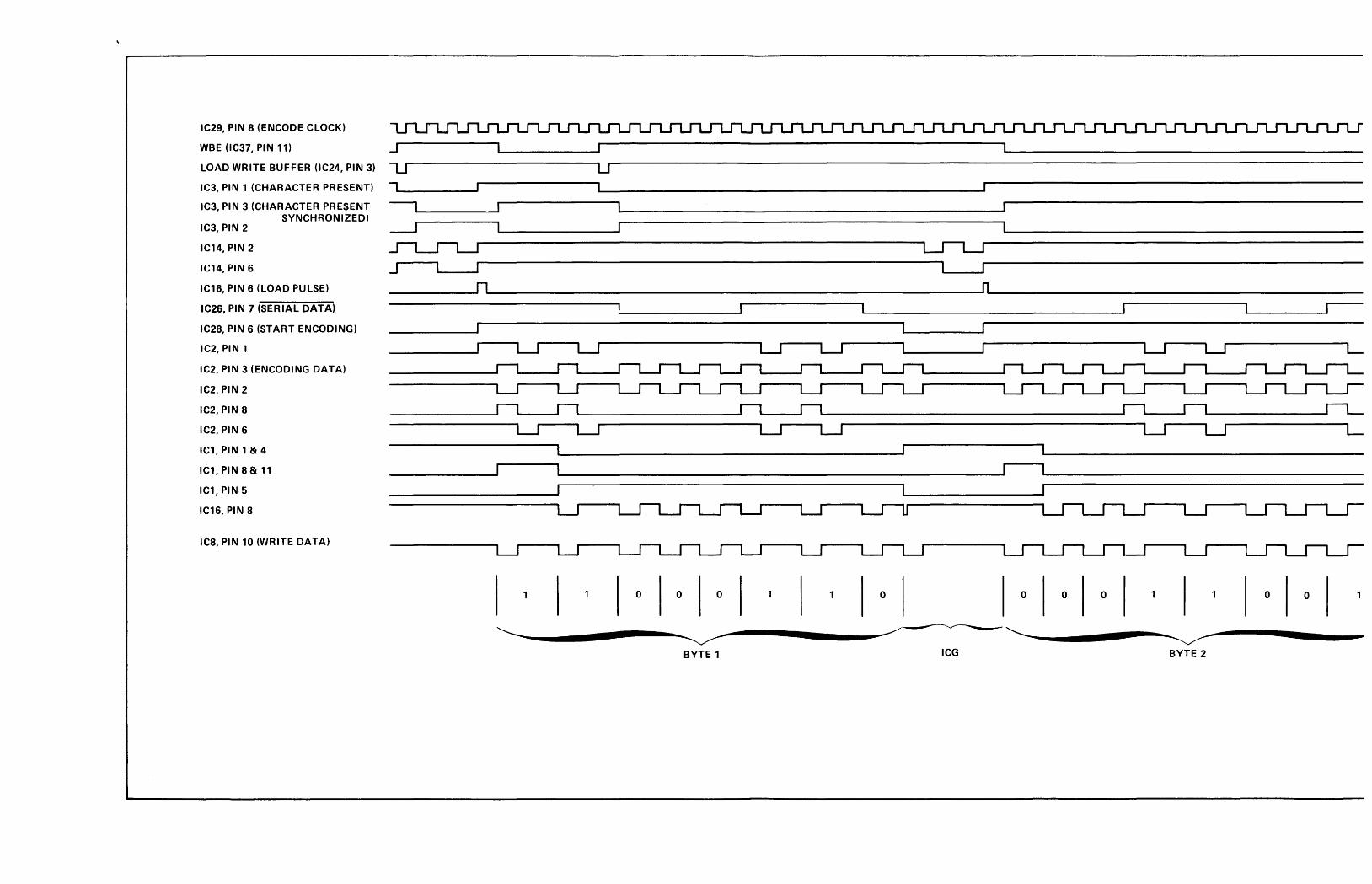
3-3-3 OPERA TION (Refer to Fold Out Schematic, (F igure 4-7)
The encode/decode PC assembly operates as described below. A write operations timing diagram (Figure 3-9) and a read operations timing diagram (Figure 3-10) are included to aid the reader.
3-3-3-1 WRITE ENCODE
1. When the WRITE BUFFER EMPTY output flag is low the user places an 8 bit byte (high for a "Zero" bit, low for a "One") on the input and applies a low going pulse on the LOAD WRITE BUFFER input (IC24, pin 3).
2. This pulse is inverted (IC24, pin 4) and is used to strobe the input byte into a buffer register (IC36). The same pulse is inverted again and used as an input to (ICI6) the write buffer empty set reset latch, caus· ing the output pin 3 to go low. This low level causes the WRITE BUFFER EMPTY output (IC37, pin 11) to go high and applies a low level to the J input of flip flop IC3.
3. On the next clock transition, the Q and Q outputs of the flip flop (IC3, pins 3 and 2, respectively), change state. The resultant low level on pin 3 is used (IC37, pin 12) to insure that the WRITE BUFFER EMPTY output remains high. The resultant high level on Q (IC3, pin 2) is used as a gate enable at ICI6, pin 4.
IC29, PIN a (ENCODE CLOCK)
WBE (lC37, PIN 11)
LOAD WRITE BUFFER (lC24, PIN 3) L.J u IC3, PIN 1 (CHARACTER PRESENT)
IC3, PIN 3 (CHARACTER PRESENT SYNCHRONIZED)
IC3, PIN 2
IC14, PIN 2
IC14, PIN 6
IC16, PIN 6 (LOAD PULSE)
IC26, PIN 7 (SERIAL DATA)
IC2a, PIN 6 (START ENCODING)
IC2, PIN 1
IC2, PIN 3 (ENCODING DATA)
IC2, PIN 2
IC2, PIN a
IC2, PIN 6
IC1,PIN1&4
Itl, PIN a & 11
ICl, PIN 5
IC16, PIN a
Ica, PIN 10 (WRITE DATA)
-, ..... ----~ ----, ..J
--.-J .s-L...rL..J J ______ ~n~ ____________________________________ ~ __________________________ n~ ______________________________________________ __
LJ LJ LJ LJ LJ LJ L
____________ ~r_1 ..... _~r_l~ __________________ ~r_l ..... __ ~r_1~ ______________________________________ ~r_I ..... ___ r_I~ _______________ r_lL_
LJ LJ LJ LJ LJ LJ L
1 o o o 1 o o o o o o
~-----...... --~ ~----.... ----~~~"- ------.... --~ ~ ----...... --~~-BYTE 1 ICG BYTE 2

____________________________________________ ~n~ ____________________________________________________________________________________________________ __
LJ LJ ~~------------------------------------------------------------
____________ ~r_1~ ___ ~r_1~ ______________________________________ ~r_l~ ___ ~r_l~ ______________ ~r_l~ ____________________________________________________ _____
LJ LJ LJ U LJ
o o 1 1 o o o o 1 o o 1
~~----.... ----~-------...... --~~~-----........ --~~-----........ --~~ BYTE 1 leG BYTE 2 IRG
Figure 3-9. Write Operation Encode Timing Diagram
3-11 May 1977

READ DATA (tC20, PIN 1)
(SYNC READ DATA) IC20, PIN 2
(READ DATA DELAY 20) IC20, PIN 5
(CLEAR/SHIFT) IC22, PIN 3
(COUNT UP) IC19, PIN 8
(COUNT DOWN) IC19, PIN 12
(DECODED DATA) IC9, PIN 7
(9 COUNT) IC12, PIN 11
(lNTERRECORD GAP) IC23, PIN 8
(lNTERCHARACTER GAP) IC22, PIN 8
RBF IC10, PIN 6
RDBEN IC24, PIN 1
(lCG 9 COUNT) IC19, PIN 6
ICC (lC31, PIN 12)
IRG (lC31, PIN 4)
DATA LINES
( ) DENOTES INTERNAL SIGNALS
1 o o o 1 o 1 ,,_/ASSUME DROPOUT THIS BYTE
Jn~ ____ ~n~ ____ ~n~ __ ~n~ __ ~n~ __ ~n~ ______ ~n~ __ ~n ______ ~n~ __________ ~n~ __ ~n _______ n~ ____ ~n~ ___________ n~ ______ ~n~ __ ~n~ __ ~n~ __________ ~n~ ____ ~
______ ~rl~ ____ ~rl~ _______________________ rl~ __________ ~r1~ _________________________ rl~ ____ ~r1~ ___________ r1~ ____ ~rl~ ________________________________ _
n n
r U
------------------------------------------------------------------------------------~IACTIVETIME1 I
~-----........ --~ -------........ --~~-----------~ -----........ --~~~''--~ ----.......... --~~ ----BYTE 1 ICG BYTE 2 ICG
May 1977

1 ... ,_/ASSUME DROPOUT THIS BYTE
____ ~n~ __________ ~n~ __ ~n~ ____ ~n~ ____ ~n~ __________ ~n~ ____ ~n~ __ ~n~ __ ~n~ ______ ~ __ ~n~ __ ~n~ __ ~n~ __ ~n~ __ ~n~ ______ n~ __ ~n~ __ ~n~ ____ ~n~ ______________________ __
____ ~r1~ ______________________ ~r1~ ____ ~rl~ ________ ~rl ______ r1~ __________________________________________________ ~n~ ______________ ~r1 _________________________ _
______________ ~r1~ ______________________________________________________________ ~rl--------------____________________________________________ ~n~ ____________ __ ____________________________________________________ ~r_1 _____________ _
~ ______ ~------------------------------------------~ L-J u
------------------------------------tIACTIVE TIMEJ L
'~ -----.......... ---~~-------------------------~--.... --~~ leG BYTE 2 leG BYTE 3 IRG
Figure 3-10. Read Operation Timing Diagram
May 1977 3-12

4. Up to this point, IC14 has been a free running counter whose output was used to generate a short duration pulse at IC 15, pin 6 every four clock periods. When IC3, pin 2 goes high, this pulse is gated through IC16 giving pin 6 a short duration low going pulse. This pulse clears IC27 and QD (lC27, pin 11) goes low, disabling the free running counter (ICI4). The pulse at IC 16, pin 6 is also used as a latch reset for ICI6, pin 2 and as the load input enable for the parallel to serial shift register (IC26). The input data in the buffer (lC36) is thus loaded into the shift register (IC26). One clock period after the pulse occurs at ICI6:, pin 6, IC3, pin 3 goes high and the WRITE BUFFER EMPTY output is enabled at IC37, pin 13.
5. When IC27 is cleared, its low output at pin 11 is ininverted at IC28, pin 6. This high level is used as a gate enable at IC 15, pin 2 and at IC 17, pin 1 to start the encode function.
6. When the encode circuit is enabled, IC2, pin 3 is low and IC2, pin 6 is high. This latter signal is fed back to IC2, pin 1 via an AND gate (lC 15, pin 11). One clock period later, the flip flop output (IC2, pin 3) changes state to the high level. If a "Zero" is to be written, IC26, pin 7 will be low. This level is inputted to ICI7, pin 13. The resultant high output is inverted at (lC28, pin 8) and the J input to the JK flip flop (lC2, pin 8) is held low and IC2, pin 6 remains high. The resultant high input to IC2, pin 3 causes IC2, pin 3 to change state once each clock period. This signal is inverted (IC28, pin 10) to form the Variable Cell Width Recording pattern for a "Zero" as described in Paragraph 3-3-2.
If a "One" is to be recorded IC26, pin 7 will be high and the state of IC2, pin 8 will correspond to the level output at IC2, pin 3. In this instance, when IC2, pin 3 goes high, IC2, pin 8 also goes high. This causes IC2, pin 6 to switch low after one clock period. Because during the first clock period (starting from IC26, pin 7 switching high) IC2, pin 6 (and consequently IC2, pin 1) is high, IC2, pin 3 also switches low at the end of the first clock period according to the rules of operation for a J-K flip flop.
This low level is applied to IC2, pin 8 and consequently IC2, pin 6 returns high at the end of the second clock period. Since IC2, pin 1 is low during second clock period, IC2, pin 3 does not switch at the end of the clock period 2 but remains low. The high input at IC2, pin 1 during' clock period 3 causes IC2, pin 3 to switch low at the end of the third period. The signal at IC2, pin 3 is inverted at IC28, pin 10 to form the variable Cell Width Recording pattern
3-13
for a "One" as described in Paragraph 3-3-2. This signal is low for one clock period then switches high for 2 clock periods before switching low again.
7. The compliment of the signal at IC2, pin 3 (IC2, pin 2) is routed to a shift enable circuit consisting of ICI (Dual J-K flip flop) and NAND gate IC16 (pin 8). At the second low going transition on IC2, pin 2 (which occurs at the end of the first data bit) IC 1, pin 5 goes high to enable the NAND gate at pin 10, ICI6. The low level occurring at ICl, pin 6 is fed back to IC 1, pins 1 and 4 to prevent further flip flop operation as a result of changes in logic state at IC2, pin 2. Thereafter, each time IC2, pin 3 goes high, a low level occurs at ICI6, pin 8. The low going excursions occurring at ICI6, pin 8 are used to step the 8 bit counter, IC27, and to shift excessive bits out of the parallel to serial shift register (lC26).
8. After eight low going transitions {lCI6, pin 8) the counter output (lC27, pin 11) goes high. This high level allows the counter comprised of the dual JK flip flop, ICI4, to count at the clock rate. Every four clock periods ICI4, pin 6 switches high and a high going pulse is produced at ICI5, pin 6. If during writing of a given byte, a second byte is entered into buffer register IC36, IC 15, pin 4 will have been set high and the pulse at ICI5, pin 6 will be gated through to ICI6, pin 6. The low pulse at ICI6, pin 6 causes operation to begin on the second input byte, commencing at step 4 above. The four clock period delay generates the required intercharacter gap between successive bytes. If another byte had not been entered during writing of the previous byte, ICI6, pin 4 will remain low, no further operation will be initiated and the WRITE DATA output to the Read/ Write Amplifier PC Assembly will remain at the high logic state as required during an interrecord gap.
3-3-3-2 READ OPERATIONS
1. The READ DATA input from the read amplifier is applied to the read data Synchronizer {lC20, pin 1). Its compliment is applied to IC20, pin 4. The synchronizer circuit generates a positive going pulse {lC22, pin 3) for each low going transition on the READ DATA input line. This circuit further interlocks transitions of the READ DATA input to the output of the crystal clock so that subsequent read decode functions occur in proper timing sequence.
2. The high going pulse at IC22, pin 3 clears the read decode counters {lC's 7, 8, and 9 (all outputs go
May 1977

low»; it pulses the shift input of serial to parallel converter (IC25, pin 8); and the low going trailing edge of the pulse steps the 9 bit counter (lCI3, pin 14) of the Error Check Logic circuit.
3. When the first low going transition on the READ DAT A input is shifted through the synchronizer, IC20, pin 2 goes high and the 7.665 MHz clock is enabled at ICI8, pin 8. This clock output, when enabled, is applied to the count up input of the updown counters of the read decode circuit. The counters then count up at the clock frequency until the READ DATA input returns high.
4. When READ DATA returns high, IC20, pin 3 goes high and the output of the clock divide circuit (lC 15, pin 8) is enabled (lCI9, pin 12). The clock divide circuit creates a low level (lCI7, pin 8) every fifth period of the clock. This low level is applied to IC 15, pin 10 to prevent every fifth clock pulse from appearing at ICI5, pin 8. The net result is that the clock used at the count down input of the up-down counters contains, per unit time, 0.8 the number of clock transitions as the count up clock input.
5. During the timing pulse of a data bit, as described in Paragraph 3-3-2, the up-down counters (IC's 7, 8, and 9) will be counting up at the clock frequency. When the READ DATA input returns high at the end of the timing pulse, the counters will begin to count down at a rate which is 0.8 that of count up operation. At the end of the data pulse, when READ DATA switches low, counter output (lC9, pin 7) is inverted and strobed into the serial to parallel register (lC25, pins 1 and 2) by the pulse generated at IC22, pin 3. This pulse also resets the counters.
If the input bit to be decoded was a "Zero" the timing pulse and data pulse would be of the same length as described in Paragraph 3-3-2. In this instance, the contents of the counters would be positive at the end of the data pulse and IC9, pin 7 would be at a low logic level. If the input bit was a "One", the data pulse would be twice as long as the timing pulse; at the end of the data pulse, the counter would contain a negative number and IC9, pin 7 would output a high level.
6. When the ninth high going pulse occurs at IC22, pin 3, both the 20 and 23 output bits of counter ICI3 in the error check circuit go high. The high level at the 23 output (pin 11) resets the interrecord gap latch and IC23, pin 8 goes high. This high level enables gates at the inputs to the latches for the READ BUFFER FULL and INCOMPLETE CHARACTER flags.
May 1977 3-14
Since these latches are not enabled until the first full byte is read, immunity to interrecord noise is provided and precludes noise from appearing as data on the Read Data bus.
7. The ninth pulse at IC22, pin 3 occurs at the start of the intercharacter gap, a timing pulse followed by a data pulse which is 4 times the length of the timing pulse. When IC's 7, 8 and 9 reach a count of -128 (all counter outputs are high except for a low on IC8, pin 7) a low level appears at NAND gate IC21, pin 8 which in turn, creates a high level at IC22, pin 8. This high level causes buffer register (IC33) to be loaded with the contents of serial to parallel shift register. It also sets the read flag latch causing ICI0, pin 6 to go high; this level is inverted to form the low going READ BUFFER FULL output.
If the counter (lCI3) had not reached a count of 9 (eight bits were not present in the byte) when the intercharacter gap is sensed IC22, pin 8 goes high (as assumed in byte 2 of Figure 34), a low level is generated at ICI9, pin 6. This low level sets the error flag SET/RESET latch and ICI0, pin 8 goes high. This level is inverted at IC31, pin 12 to form the INC OM -PLETE CHARACTER output flag. Sensing the intercharacter gap (high level at IC22, pin 8) also causes a high going pulse to occur at ICI2, pin 6. This pulse clears the 9 bit counter (lCI3) of the error circuit.
8. If the timing pulse in 7 above is at the end of a reccord, the counters, IC's 7, 8 and 9 will continue in a negative direction. When a count of -512 occurs (all counter outputs are high except for a low on IC9, pin 2), a low level occurs on IC23, pin 3 which sets the interrecord gap latch and IC23, pin 6 goes high. This level is inverted at IC31, pin 4 to form the low going INTERRECORD GAP, output. The low output at IC23, pin 3 also disables the clock inputs to the up down counters at ICI9, pin 2 and at ICI9, pin 9.
9. After the READ BUFFER FULL output goes low, the user must apply a low going pulse of at least 50 nanoseconds duration to the READ BUS ENABLE input. This pulse enables the tri-state data output gates (IC's 32 and 34) and resets the read flag and error flag latches.
3-3-4 INTERRECORD GAP TIME CONSIDERATIONS
To insure the writing of proper length interrecord gaps, the following delays should be used.
1. After commanding forward tape movement, delay 27 milliseconds before entering the first data byte.

2. After writing (or reading) the last data byte, delay 5 milliseconds before commanding a stop.
3-3-5 WRITE FLAG TIMING
When writing data, the following timing restrictions must be considered:
1. When the first byte of data is strobed in, WRITE BUFFER EMPTY will go low again within from 16.67 microseconds to 83.5 microseconds, depending on internal logic timing.
2. The LOAD WRITE BUFFER input must be a pulse of at least SO nanoseconds but no greater than 1.5 microseconds. The LOAD WRITE BUFFER input must occur no sooner than 4 microseconds but prior
3-15
to 340 microseconds after WRITE BUFFER EMPTY goes low.
3-3-6 READ FLAG TIMING
When reading data, the following timing restrictions must be considered:
1. Mter the first byte is decoded, subsequent bytes will occur on the average, every 350 microseconds.
2. The READ BUS ENABLE input must be held true for at least SO nanoseconds for valid data to appear on the data bus. This input must occur no sooner than 20 nanoseconds after READ BUFFER FULL goes low. READ BUS ENABLE should return high within 200 microseconds of READ BUFFER FULL going low.
May 1977

SECTION IV. PARTS LISTS, SCHEMATICS, AND PC BOARD LAYOUTS
Parts List, DCD-l Mechanism Assembly
INDEX NUMBER PART NUMBER DESCRIPTION QTY.
1 81-1530-9670-6 Ejector Slide 1 2 81,(,)930-9770-7 Spiral Pin - 3/32 DIA x 3/16 L 1 3 83-92604501-0 Screw - Mach., Pan Hd., 2-56 x 3/16 2 4 83-92614201-5 Washer - Lock, Flat, Int. Tooth, #2 1 5 83-9260-2001-3 Nut - Hex, Plain 2-56 x .188 WD 1 6 83-9261-21324 Screw - Cap, Skt. Hd., 440 x 5/16 1 7 83-92604507 -7 Screw - Mach., Pan Hd., 2-56 x .625 1 8 81-2716-1860-5 Head - Single Track R/W 1 9 81-1630-9870-0 Head Insulating Tape 1
10 83-0003-09704 Cable Assy. Head 1 11 81.(.)934-3480-1 Ball - Azimuth Adjust 2 12 81-1432-6660-9 Screw 6-32 x 5/16 Pan Head 5 13 83-0003-0993-6 Mechanism Base Assy. 1 14 81-1330-9880-6 Spring - Eject Release Slide 1 15 83-7270-0878-7 Ring - Retng., Ext., .113 Free Dia. 13 16 81-0150-0008-6 Eject Button Assy. 1 17 81-0930-9540-4 Ring - Retaining, Reinforced E 2 18 83-9261-0071-6 Setscrew - Cup Pt., 8-32 x 3/8 2 19 81-1330-97204 Motor Spring 1 20 81-1332-1000-5 Spring - Azimuth 1 21 81.(.)9344680-5 Nut - Stop, 2-56 1 22 81-0430-9620-5 Whiffle Tree Shaft 1 23 81-0430-9790-6 Roller - Detent Lock Arm 1 24 81-0330-9440-0 Release Rocker Arm 1 25 83-0003-0985-2 Detent Lock Arm Assy. 1 26 83-9261-2003-7 Screw - Cap, Skt. Hd., 440 x 1/2 1 27 81-1317-7120-6 Spring Bank Item 1 28 81-0430-9750-0 Shaft - Right Lock Arm 1 29 83-7270-0876-1 Ring - Retng., Ext., .072 Free Dia. 4 30 81-0430-9780-7 Shaft - Detent Lock Arm 1 31 83,(,)003-0988-6 Rear Lock Arm Assy. 1 32 81-0430-9570-2 Roller 2 33 83-0003-0987-8 Right Lock Arm Assy. 1 34 81-1330-9930-9 Spring - Rear Lock Arm 1 35 83-0003-0984-5 Right Lock Cross Bar Assy. 1 36 81,(,)330-9830-2 Link Right Lock Arm 1 37 83-0003-0969-6 Cable Assy. Motor 1 38 81-0330-9480-6 Bottom Cover 1 39 83-0003-09944 Motor Assy. 1 40 81-0430-95504 Motor Pivot Shaft 2 41 81-0334-3350-9 Retainer - Motor Pivot 2 42 83-0003,(,)990-2 Transfer Bracket Assy. 1 43 83,(,)003-09894 Transfer Pivot Bkt. Assy. 1 44 81-1330-9900-2 Return Spring - Transfer Bkt. 1 45 83-0003-0986-0 Left Lo ck Arm Assy. 1 46 81-0430-9760-9 Shaft - Left Lock Arm 1 47 81-0330-94004 Link - Lock Arm 1 48 83-0003,(,)992-8 Right Guide Rail Assy. 1 49 83-9260-2001-3 Nut - Mach. Screw Hex 2-56 2 50 83-0003-0991-0 Left Guide Rail Assy. 1 51 83-92604519-2 Screw - Mach. Pan Hd., 440 x 5/8 1
May 1977 4-0

L' t DCD·1 Mec Parts IS, hanism Assembly (Cont.)
DESCRIPTION . PART NUMBER
d 440 x 5/16 Screw - Pan H P Hd 440 x 1 83·92604514·3 Ma h an ., Screw - c.,
52 83·92604522-6 53
54 81·1530·9640·9 Front Bezel 1 1 2 Lug d 2-56 x 3/4
1
83·9630-0085·2
Screw - Pan H "bly (includes item 50)
1
55 81-14344820·7
End Sense Asse~
2
56 834930·3905·7
W sher #4 PlastIC .
2 a S Aclion OOA
57 81-0884·2440-8
Switch - nap Sens FPTI
1 NPNPhoto
58 83-1550-6166-2
TSTR - SI Lens End TS1748
59 81-2712-7041-5
Lamp -2.SV 60
81-2712-1310-0 61 62 81-0430-9520-7 Washer - Shoulder 1 15 63 83-0003·t"016-S Head Oamp Assy.
50
. Drive Unit, Ex loded View, Figure 4-1. Pha 'cal Assembly Mec ru
4-1 May 1977

NOTES
May 1977 4-2

R12 CR2
R13
R14 R 15 -._..I<='l_.I=
VR1
R16 R17
R18
INDEX NUMBER
C1 C3 C4 C5 C6 CR2 ICI HA,IB LSI QI,Q2 Q3 Rl,2 R3,18 R4,5 R6 R7 R8, 9,14,15 RIO, 11 R12
R13 RI6,17,18 SWl,2 VRI Not shown
R7 R6 R4 R5 J1A J1B 03 01 02 LS1
MI---C1 .---R3
R10 R11 R9 R8 SW1 SW2
Figure 4-2. End Sense Amplifier Board Component Layout
Parts List, End Sense Amplifier PC Assembly, 834930-3905-7, Issue E
PART NUMBER DESCRIPTION QTY.
83-15104648-5 Capacitor - Fixed, Film, 1 UF 100V 10% I 83-1510-2354-2 Capacitor - Fixed, Elc, 100 UF 16V 1 83-1510-1024-2 Capacitor - Fixed, Ceramic, 1000 PF 1000V 10% I 83-1510-5120-4 Capacitor - Fixed, Mic, 500 PF 500V 5% 1 81·1510-10754 Capacitor - Fixed Ceramic, .01 UF 10V 1 83-1530-0083-7 Diode - SI Switching IN914 1 83·1530-8307-2 IC - Quad Comp LM339N 1 83-1610-1912-6 Connector - 5 Contact 2 81-2712-1310-0 Lamp - 2.5V Lens End TSI748 I 81·2712·7041·5 Transistor - SI, NPN Photo-Sens FPT100A 2 83-1530-2434-0 Transistor - SI, NPN Power-Dad MJE800 1 83·9520-2223-0 Resistor - Fixed, Comp, 22M Ohm 1/4W 5% 2 83-9520·2088·7 Resistor - Fixed, Comp, lK Ohm 1/4W 5% 2 83-9520-2089-5 Resistor - Fixed, Comp, 8.2K Ohm 1/4W 5% 2 83-9520-2167-9 Resistor - Fixed, Comp, 39K Ohm 1/4W 5% 1 83-9520-2132-3 Resistor - Fixed, Comp, 200 Ohm 1/4W 5% 1 83-9520-2112-5 Resistor - Fixed, Comp, 10K Ohm 1/4W 5% 4 83-9520-2195-0 Resistor - Fixed, Comp, I.3M Ohm 1/4W 5% 1 83-9520-2182-8 Resistor - Fixed, Comp, 300K Ohm 1/4W 5% 1 83-9520-2162-0 Resistor - Fixed, Comp, 20K Ohm 1/4W 5% 1 83-9520-2098-6 Resistor - Fixed, Comp, 2.7K Ohm 1/4W 5% 3 83·1550-6166-2 Switch - Snap Action 2 83-1530-0465-6 Diode - SI Zener 6.8V 1 83-0003-0991-0 Guide Rail, Left, Assy 1 83-9260-4501-0 Screw Pan Head 2·56 x 3/16 1 81-1434·4820-7 Screw Pan Head 2·56 x 3/4 2 83-9620-2001·3 Nut Mach. Screw Hex 2·56 2 81·0884·2440·8 Washer #4 1
COMPONENT SIDE
R15 10K
VR1 C6 1N473SA .0111f 6.SV
':"
R2 +12V 22M
RS 39K
R7 200n
':"
R1 22M
C6 500PF
r R14 10K
+12V
R3 1K
R4 B.2K
R5 S.2K
':'
':'
CR2 1NS14
R13 20K
R11 1.3M
R10 1.3M
13
R12 lOOK
2
+12V
Pl17 2.7K
+12V
+5
+5
R18 2.7K
RS 10K
RS 10K
J1
CIN
PC2
+5
PC1
+12V
'--................. .J LSI TS 1748
CARTRIDGE POSITION SWITCH S2
IN N.O.
I I C I ~-__
OUT' N.C.
r----o N.C.
J+-----....... ~ +5V
C4 O.OO1j.lf
H------+--_~ +12V
Figure 4-3. Schematic, End Sense Amplifier PC Assembly 834930-3905·7 Issue E
4-3 May 1977

May 1977
C24 C25
R73
J5 R71-,-~ __ "'"ftiiW"'l
R72~~=:m R70 R69 R59 4----r_+_~ R58 J4B J4A R45 R46 C30 R47 R11
R60 THRU R67 R15 C14 R13 C12 R12 J1A J1B C16 R8 C6 R7 c::::::::>C5 R5~
R4 =8f4
C
Parts List, Servo Electronics and Read/Write Amplifier PC Assembly 834930-3904-0, Issue E
INDEX NUMBER PART NUMBER DESCRIPTION QTY.
CI,6-10 83-1510-2307-0 Capacitor - Fixed, Ceramic, .05 UF 10V 6 C2 83-1510-6415-7 Capacitor - Fixed, Tan, 2.2UF 3SV 10% 1 C3,28 83-1510-6413-2 Capacitor - Fixed, Tan, 1.0 UF 3SY 10% 2 C4, 5,11 83 -151 0-1 024-2 Capacitor - Fixed, Ceramic, 1000 PF 1000V 10% 3 C12 83-1510-5041-2 Capacitor - Fixed, Mic, 1000 PF SOOV 5% 1 C13,14 83-1510-1187-7 Capacitor - Fixed, Ceramic, .1 UF SOV 2 C15 83-1510-5164-2 Capacitor - Fixed, Mic, 150 PF 500V 5% 1 C16 83-1510-5263-2 Capacitor - Fixed, Mic, 2 PF 500V 1 CI7,19,30 83-1510-10754 Capacitor - Fixed, Ceramic, .01 UF 50Y 3 C18 83-1510-2355-9 Capacitor - Fixed, Etc, 100 UF 16Y 1 C20 83-1510-6411-6 Capacitor - Fixed, Tan,.47 UF 35V 10% 1 C21, 22 83-1510-6126-0 Capacitor - Fixed, Tan, .18 UF 35V 10% 2 C23-27 83-1510-4649-3 Capacitor - Fixed, Film, .01 UF 100V 10% 5 C29 83-1510-5028-9 Capacitor - Fixed, Mic, 470 PF 500V 10% 1 CRI 83-1530-0151-2 Diode - Rectifier 1 N4004 1 Fl 83-7550-8159-9 Fuse - 2 Amp, Microfuse 1 HSI 81-0930-9710-3 Heat Sink 1 ICI 83-1530-8162-1 IC - Dual One Shot SN74123N 1 IC2 83-1530-8163-9 IC - Dual J-K SN74107N 1 IC3 83-1530-8171-2 IC - Shaft Req SN74194N 1 IC4, 6, 16 83-1530-8142-3 IC - Hex Inverter SN7404N 3 IC5,7 83-1530-8060-7 IC - Quad 2 Input NAND SN7400N 2 IC8, 12 83-1530-8069-8 IC - Dual 4 Input NAND SN7420N 2 IC9, 10 83-1530-8143-1 IC - Tri 3 Input NANDD SN741 ON 2 ICl1 83-1530-8168-8 IC - Quad 2 Input AND SN7408N 1 ICl3, 15 83-1530-8333-8 IC - Quad 2 Input OR SN7432N 2 IC14 83-1530-8356-9 IC - Hex, Tri·State SN74125N 1 IC17,20 83-1530-8174-6 IC - Hex, Inverter Buf SN7406N 2 IC18 83-1530-8358-5 IC - Op Amp 8 Pin Dip SN72748P 1 ICI9 83-1530-8307-2 IC - Quad Comp LM339N 1 IC21 78-8032-2739-2 IC - Quad Op Amp LM324N 1 JIA,IB 83-1610-1912-6 Connector - 5 Circuit 2 12,3,5,6 83-1610-1913-4 Connector - 5 Circuit 4 J4A,4B 83-1610-1914-2 Connector - 4 Circuit 2 17 83-1610-1915-9 Connector - 3 Circuit 1 J8 83-1610-1916-7 Connector - 6 Circuit 1 J9 81-28174620-6 Connector - 2 Circuit 1 Pl,2 83-1610-1907-6 Plug - Jumper 2 Ql 81-2712-5290-0 Transistor - SI, NPN Low Power 2N3416 1 Q2,3,6,7,8 81-2712-5530-9 Transistor - SI, NPN 7553A 5 Q4,5 83-1530-2424-1 Transistor - SI, PNP High Power MJE2955 2 Q9,10 83-1530-2425-8 Transistor - SI, NPN High Power MJE305S 2 Qll 83-1530-2155-1 Transistor - SI, PNP Low Power 2N3638A 1 Rl,3 83-9520-2164-6 Resistor, Fixed, Cmp, 24K Ohm 1!4W 5% 2 R2, 8, 14, 19, 83 -9 5 20-2088-7 Resistor - Fixed, Cmp, lK Ohm 1/4W 5% 10
24,44,54, 55,59,67
R4 83-9520-20994 Resistor - Fixed, Cmp, 82 Ohm 1/4W 5% I R5,86 83-9520-2107-5 Resistor - Fixed, Cmp, 100 Ohm 1/4W 5% 2 R6,75,81 83-9520-2132-3 Resistor - Fixed, Cmp, 200 Ohm 1/4W 5% 3 R7 83-1520-7349-6 Resistor - Fixed. Film, 300 Ohm 1/2W 2% 1
4-5 May 1977

Parts List, Servo Electronics and Read/Write Amplifier PC Assembly (Cont.)
INDEX NUMBER PART NUMBER DESCRIPTION QTY.
R9 83-95204144-6 Resistor - Fixed, Cmp, 510 Ohm 1W 5% 1 RIO 83-1520-7174-8 Resistor - Fixed, Film, 390 Ohm 1/2W 2% 1 Rll,70 83-1520-1574-5 Resistor - Variable, Ceramic, 1K Ohm 2 R12, 13, 18 83-1520-7308-2 Resistor - Fixed, Film, 10K Ohm 1/4W 2% 3 R15 83-1520-7259-7 Resistor - Fixed, Film, 20K Ohm 1/4W 2% 1 R16 83-1520-0356-8 Resistor - Fixed, Film, 150 Ohm 1/4W 2% 1 R17, 23, 29 83-9520-2112-5 Resistor - Fixed, Cmp, 10K Ohm 1/4W 5% 5 37,38 R20, 21 83-1520-7282-9 Resistor - Fixed, Film, lK Ohm 1/4W 2% 2 R22, 4143, 83-9520-2096-0 Resistor - Fixed, Cmp, 3.9K Ohm 1/4W 5% 6
84,85 R25, 26 83-9520-2152-1 Resistor - Fixed, Cmp, 4.3K Ohm 1/4W 5% 2 R27,34 83-9520-2095-2 Resistor - Fixed, Cmp, 3.3K Ohm 1/4W 5% 2 R28,35 83-1520-0500-1 Resistor - Fixed, Film, 499K Ohm 1/4W 1% 2 R30 83-9520-2119-0 Resistor - Fixed, Cmp, lOOK Ohm 1/4W 5% 1 R31,32 83-9520-2162-0 Resistor - Fixed, Cmp, 20K Ohm 1/4W 5% 2 R33 83-9520-21794 Resistor - Fixed, Cmp, 180K Ohm 1/4W 5% 1 R36 83-9520-2180-2 Resistor - Fixed, Cmp, 200K Ohm 1/4W 5% 1 R39,40 83-9520-2172-9 Resistor - Fixed, Cmp, 82K Ohm 1/4W 5% 2 R45, 46, 61, 83-1520-0501-9 Resistor - Fixed, Film, 15K Ohm 1/4W 1 % 6
63,65,66 R47 83-1520-0502-7 Resistor - Fixed, Film, 68.1K Ohm 1/4W 1 % 1 R48,49 83-1520-0503-5 Resistor - Fixed, Film, 47.5K Ohm 1/4W 1 % 2 R50, 53 83-1520-0504-3 Resistor - Fixed, Film, 78.7K Ohm 1/4W 1 % 2 R51 83-1520-0505-0 Resistor - Fixed, Film, 57.6K Ohm 1/4W 5% 1 R52 83-1520-0506-8 Resistor - Fixed, Film, 158K Ohm 1/4W 1 % 1 R56 83-1520-7220-9 Resistor - Fixed, Film, 220 Ohm I/2W 2% 1 R57 83-1520-7340-5 Resistor - Fixed, Film, 68 Ohm 1/2W 2% 1 R58 83-1520-0507 -6 Resistor - Fixed, Film, 54.9K Ohm 1/4W 1 % 1 R60, 62, 83-1520-05084 Resistor - Fixed, Film, 243K Ohm 1/4W 1% 4
64,68 R69 83-1520-1568-7 Resistor - Variable, Ceramic, 20K Ohm 1 R71 83-1520-1573-7 Resistor - Variable, Ceramic, 500 Ohm 1 R72 83-1520-0509-2 Resistor - Fixed, Film, 2.74K Ohm 1/4W 1 % 1 R73 83-1520-0510-0 Resistor - Fixed, Film, 221 Ohm 1/4W 1 % 1 R74, 79 83-1520-7339-7 Resistor - Fixed, Film, 62 Ohm 1/2W 2% 2 R76, 78 83-1520-7332-2 Resistor - Fixed, Film, 30 Ohm 1/2W 2% 2 R77,80 83-95204132-1 Resistor - Fixed, Cmp, 120 Ohm 1 W 5% 2 R82,83 83-1520-7342-1 Resistor - Fixed, Film, 82 Ohm 1/2W 2% 2 R87 83-9520-2232-1 Resistor - Fixed, Cmp 10 Ohm 1/4W 5% 1 VRI 83-1530-0389-8 Diode - Zener 1O.0V IN4708A 1 VR2 83-1530-0377-3 Diode - Zener 5.1V IN4733A 1 VR3 83-1530-0376-5 Diode - Zener 7.5V IN4737A 1
May 1977 4-6
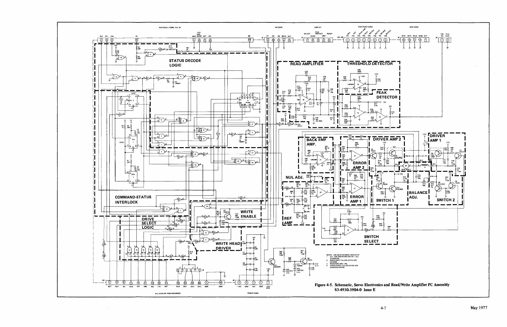
PHOTOCELL CONN. J1A. 18
Pe2 PC, CIN FP
+'2V END
GND SENSE KEY +5V
HocorlN
WI' CT HO HD SHLD KEY
DISPLAV
SELECT
+5\1OC
FILE PROTECT
GND
TEST POINT CONN MfR CONN
(:);,.0 ~¢ ~",~O~:~cl ~o"'o~ ~o"'o~ 'I><i'<s>'" 'I>~,<s>'" TPS TP10
TP' TP2 TP3 TP.. TPS TPS TP7 TPS MfR MTR SHlO SENS KEY AD GND J2~~~--__ -=~ __ ~ r: ~ IV (V ® G) (! ~ G) 121 - _CV ~ ~ ~ ~
1 rl -~ -~ .1-~+5~ - - .~- - - ,: :-~~&1 R87 1 I 1 IL-------, L J 1 ~ 8 ~ r-_ell!!!!! T ! r- ~'---f----1f 1'---+--11+----=-,3 ~ I '"10 01
1 I
R8 19 _ v PROTECTL'2V>-,-N'8_-----+------+.:..:
5V:...------------------------------Ir--.
l' R6 10 I l~K ~ ..... 1'\....8 L.;; _____________ _
12 13 200
I ~ STATUS DECODE I LOGIC r - READAMPLiFlER - - r- -THREsHOLDDETEcTOR' I 1 R36 I
~II I~ _: _ ~'3 _):3~ __ +-~ __ "!;'-55-"'_ }L3~ _~4 .'2 ~ 10 :, 6 /1:>'''---~~~~~-'0''''~ a 5 4,::;:.06"---______ -+-+-______ -+ __________ ---, I ~~ R'6 1 R37 ~ +12V I ~ r--- ~io J- C5 I ~ v I ~~. ~~ I 10K 1 9 + 3 ~.ft. 1 L--------~----H,....J l 'OOOPF I C15 +12V 1 lM339N r 19 14 1
.I ~~O'jPF R,K,g ~ I 12 R35
I R12 11 ;ri: ... ~~8 I R38 ~ 499K r- - - - -. .--+-++--+-__ -'-' ~~ 1 ~--,+-,314 5W- g~3 ~K 2~ ~ 2% 10% II-I_ =- _ ~:"...I PEAK I
t 10 el A • C D:~' t- II e'2 J 'ZT IP3 • ~:" DETECTOR 1
I
: ~ c." 2 Q 2 .---____ -+-+-1---__ .!.9-l& I:Sl 7'~94 C: 7 I : :r:~~' 7~1~'8 C~7 Rll 1% +12v
r-
TCl Q~:",--+-+-'I GAOB 00 R I. v • 0.01 1. +12V I R26 R27 I
15 1.1 13 121 21 I • C14 R13 ".3K 3.3K +5V
L-__ +-__ ....J13 I I I L- L 0.1 ~K ~~~ ~~o I R25.l 2 ~':K 7.., R2. I
'~ 8 .r1h-----... T I g.~~ I ~t~ J cIa R21 I 4.3KJ R29 19 ~' -t-'"-" -----.I-----------------------...J r+-~ I .----__ +--_-+-+---+ __ +-+-----<>-+-+-+--_-+--J1 ~ -: .. I. 4/ 19 ~ I
+5 +5 I. 9' 11 ~I- ~.~~ - 1'00 ,. I C29 ~ 10K 6 I R21 R3l II ~ 9 "):>"-6 +_HI1II-+1H--¥5.q1' 6 3 1~4 ~5 -, -~ -20 +80% ~ ~~F T -1K 24K C3 1 ~.R II (ROY) a.. ____ L.: _________ -I
~~9~ ~11 I ~ 11~% II ~ I ~ 12 \ 9 .~8~NR"" _.l....!.!J-4-!'4~_ 55-, ~ 11 lJ rt' C23 '+ i'2V r DRiVE: R- - - .., 15
y ____ --f......!.,l A 7m. rI '----'j'j 9rf- 2 C~2 4-I ~AckTMT' r -~~~- _~~9_ T DRTvER' AMP2' lAMP 1 I
74123 1 I: ~ .5-r-7 \..6 l000PF ~ I I J
2 _ 4 ~ U r- AMP. ~P4 TP ~~K I +12V 1 ~1' +12V 1 l,B 3cr~L+_~~rt------':il-~-y3'--I;::::tI--==-==-=:t-9P"_:::_"- - .1- -~ ... " - - - -. - -1-1 I R47 R61 HSI I 681" I I 15K I R75 r----i ,-----,R81 R80 I
Rl 2'"
~ --+----------+-J1 ~6 2 ~ 12 • 9 6'>"-8-+-+-l __ +--+ ___________ ~5 11 ~. -+-HIII-1I-+-f-+> I r~ ~~---+1-2V .... ,"'%V'---> I I~~ 13 14 I. ?:) R::
O
: (-t1 : TI i; as ~"\ : 200 ~~O ?;53A
... V I "121- :1- 4 '5K 21 '.\~~ 120 I ~ 04 'TPSo----. r-+--oTP7IL~~J tu-I ~12ri yJ I I ~::. LM324N 21 1 ~ • ,% 12 + I. '--=' R~: C;. -- ~g9~ J53 1.:;;;. - C27 ~
~ ~ / ----st 10 I 1% 3 R7Q IR62K
{ VERROR I 62 0.01 ..,-1- I"'"r- -.... 0.01 ~i9 I J~ ~l ~ 6 I ~~".;; ~" lK I I ~~Kl AMP 2 I A76 1I2W 10% J5-4JiI - Ml + .5 iIn IlL,J55 10% 1/2W R78 I
II ~ I 1% Vref - - - --- 30 MTRA$BlY 30 L-l£.,.,5m. L __ I_---" I 1/2W ~lV----IiiiioiiI--Iiil--iiilii-' --+~ 1i2W U
II 1 I NUL ADJ. ~: ~v"r =- ~~7 ~~K ~~ t,:M~R83 ....... -<>TP6 R721 g~~ ,-,T
1P5o-- A8~1 ~ """I
II 9~A CL a 12 .-- _____ ~ __ 47.5. 1 I~:~ 1% 1 ~~2W ~~4~1 10% ... 1' ... 1: ~~2W aB
I R53 R50 1% I LI. 1% 9.., 07 '-. ,:~ 09 11 78.7K 78.7K [ -> 7553A tv -I ~~ 1 ~J: ~MJE.3055 -'S53A I
II II 11 ~ 10 1% 1% 6.... II R65 I I • v9 - I 11 '5• 21 8 ~ f- ~~3055 1% 1-+---'<.:--
II II 1 ~ + ~~ I~~~· l3> 7 .'% 10 ~ ~~ l I BALANCE I h~~ I II COMMAND-STATUS ~ 3~,.?'4 __ --t-+"LJI--+-t-+--+-- V .. f + e21 5 + I I~~J ERROR I "l ~ ADJ. I ~ l I II INTERLOCK .--_~I_ v---, ~ - - -.- - - -- - - - ~I-~ 113~ ~~ :~K- ~30~'PS __ .J_L:' ~':2._~ lc- ~~~1.,._ J L ~W_IT~ _2 . • I ~-------~+LH-k-I.! -B'-61pJ0 8 I ~ I I V J7 -1- r ,.... ,..,.. -I
II Ll-l--t--___ -+==========~f 9 7 I R9 ~' WRITE· I I .I 510 2N3416 Al0 I RS1 60 IPS
. +5V I Cl1
0.001
1- -.1-- - -r - - I- D'RWE- - - -6-~~ I ~~12~-I_'W-+-+\--If-.. i'l'~w ENABLE. I REF ~~6K+r~~ I 1
I. '4 f- l 13..D.. '2 ' ~VRI I A r-~ SELECT 8 ~~ 9 I ~ '~;~~740A I ~~ _ -= _ J
! I LOGIC 11'3~'2 ... ---· .. --T-...,....---
A43
~ 1 R33 6
180" R41 L ~ A42 R44 I +5V
A32
~
v .. ,
I I .---------------=:"----------+--I-!----1 ~ 8 I I 2 I ~~ ll" 1~3 11~ '0 1 +5V
1 ~"~ I 8 6 3 8 " l7 !:E~~ WRITE HEADI~":.. >-if-
:f~ :~J 19 13 3:~i>o_4~----3.9-·-4--""K'I'----i_f_-------------------------------1 1 v SWITCH I I ~ SELECT
II I (: r: (,':J (,; 15 R14 \. - - -P.!i!'!S.R __ I C7 ~~ g~ lOr 4rs 2H ,or '3 12 ~~ lK r O.05I'~ ,. I 6 16 5 8 16 9 I 3 _,,- _ .. __ 1_ ........ ___ -.I--.J Mf- ~05
o I 1 2 3
I:> C> 0 Q 6 oj J8
_____________ ..J
~fw ~2W RB6 06
180 ~'7 CRI \..~7:3A~ v ... ,
~~~638A 1 N4004 1 5 1V
+12V ,,",VR3 rlc- VR2 g~~
NOTES: UNLESS OTHERWISE INDICATED " Alll/2W RESISTORS ARE 2% - ALL
OTHERS 5%. 2 RESISTANCE VALUES GIVEN ARE
IN OHMS. 3. RESISTORS ARE 1/4W. 4. CAPACITANCE VALUES GIVEN ARE
IN MICROFARADS I I 1
L _COl CD lV lV (u r!l (1~ (1~ (1~ ('!l 1 1
~, R57
. l' ;,:> lN4737A i;"lN4733A I I 75V 51V Ir----f------+--+--+-I---.J ~ ~ ~
- J6 0 (~ 0 001 BOT RDV STP RWC WD FIR RST ENO EN' EN 2
All EVEN NO. PINS GROUNDED
EN3 GND GND +12V GND +5V GND +12V MTR
Figure 4-5. Schematic, Servo Electrorucs and Read/Write Amplifier PC Assembly 83-493()'3904-0 Issue E
4-7 May 1977

May 1977
o
R5 ~
oCEJo C12 C7
Gn R4
GJ C1[J
R 3 ==e::::::F=>
Gn oGlJ C6
o
o
Figure 4-6. Encode/Decode Board Component Layout
4-8

Parts List, Encode/Decode PC Assembly 834930-3906-5, Issue C
INDEX NUMBER PART NUMBER DESCRIPTION
Cl, 2, 6, 8, 83-1510-2307 -0 Capacitor - Fixed, Ceramic, .05 UF 10V 10-12
C3,4 83-1510-1077-0 Capacitor - Fixed, Ceramic, .1 UF 10V C5 83-1510-1095-2 Capacitor - Fixed, DSC, 100 PF 1000V 20% C7 83-1510-1158-8 Capacitor - Fixed, Ceramic, 220 PF 1000V 10% C9 83-1510-1151-3 Capacitor - Fixed, Ceramic, .01 UF 200Y 10% C13 83-1510-5103-0 Capacitor - Fixed, Mic, 330 PF 500V 5% C14 83-1510-1024-2 Capacitor - Fixed, Ceramic, 1000 PF 1000Y 10% ICI-3, 14,20 83-1530-8163-9 IC - Dual J-K SN74107N IC4 78-8005-8300-3 IC - 4 Bit Synchronizer Counter SN74163N IC5 83-1530-8359-3 IC - Crystal Oscillator MC12061P IC6,11, 83-1530-8142-3 IC - Hex Inverter SN7404N
24,28 IC7-9 83-1530-8357-7 IC - 4 Bit Synchronizer Counter SN74193N ICIO,12, 83 -15 30-8060-7 IC - Quad 2 Input NAND SN7400N
16,23 ICI3,18, 83 -1530-80664 IC - 4 Bit Counter SN7493N
27,29 IC15,22 83-1530-8168-8 IC - Quad 2 Input AND SN7408N IC17,19 83-1530-8143-1 IC - Tri 3 Input NAND SN7410N IC21 83-1530-8061-5 IC - 8 Input NAND SN7430N IC25 83-1530-8320-5 IC - Shift Register ParI Out SN74164N IC26 83-1530-8172-0 IC - Shift Register ParI Load SN74165N IC30 83-1530-8271-0 IC - Hex Buffer Driver SN7417N IC31 83-1530-81894 IC - Hex Inverter Driver SN7416N IC32,34 83-1530-8356-9 IC - Quad Tri-State SN74125N IC33,36 83-1530-8355-1 IC - Latch 8 Bit BSTBL SN74100N IC35 83-1530-8242-1 IC - Decoder Dual 2LN-4LN DM74155N IC37 83-1530-8341-1 IC - Quad 2 Input NAND SN7438N J1 83-1610-19134 Connector - 5 Circuit J2 81-2817-4590-1 Socket - 14 Pin Dip RI-3,5, 83-9520-2088-7 Resistor - Fixed, Comp, lK Ohm 1!4W 5% 8-13
R4,6,7 83-9520-2107-5 Resistor - Fixed, Comp, 180 Ohm 1!4W 5% R14 83-9520-2139-8 Resistor - Fixed, Comp, 510 Ohm 1!4W 5% RNI 83-1520-0492-1 Resistor - Fixed, Network, 330/220 Ohm Yl 81-2716-6011-0 Crystal, 7.665 MHz Fund Serial Resistor
QTY.
7
2 1 1 1 1 1 5 1 1 4
3 4
4
2 2 1 1 1 1 1 2 2 1 1 1 1 9
3 1 1 1
~----r-----r-----------------~ I CLOCK -5V I -5V CLOCK I READ DATA SYNCHRONIZER I I I R2 DIVIDE I I 5~ I 'K I, ' J 7"07 Q 3 8 J Q 6 I
W I I I I '2 CK
I I' · I I I '0 I I I ________ ~
: :~:L:J I READ '''" :
I ~,'~ I ,. 2 I I I I L ,~~ I I I I
I I
12 6 5 4
I~~~~~~~--------~~ ----'3--- , ,2 37 ):>"-,-' --+------+---+--111-1+-_
7438 I ,+-----~~4_--~+_--
. WRITE FLAG: Q 3
LOGIC R7
I '80 ~ _____ ~ L..~¥--_i!.<:l '>!L--_--+--J!Ji -- ~
I
lL __ _
I +5V
I I I
~~~-------------------------+--~I
ENCODE TIMING CONTROL
I I I I L ___________________________ ~
..---1-.....

QTY.
7
2 1
1 1 5
4
3 4
4
2 2
1 2 2
1 1 9
3
+5 GNO GNO we RD ROY BOT RST F'R RUN STP Rwe
NOTES FOR USER IN/OUT
1 OPTIONAL NETWORK FOR USER CABLE LENGTH GF~EATER THEN 4 FT IF NETWORK IS UGED USER MUST EMPlOV BUFfER DRIVER GATES
2 ALL NON TFHSIATE G~\TES REGUIRE PULLUPS AT USER END
3 DATA BUSSHOULO BE: TERMINATED iIo'lTH TRISTATE GATE'S
EN3 EN2 EN1 t:NO
Figure 4-7. Schematic, Encode/Decode PC Assembly 83-4930-3906-5, Issue C
4-9 May ~977

APPENDIX I. WARKA'N'TY
DCD-l DATA CARTRIDGE DRIVE WARRANTY
MINCOM DIVISION/DATA PRODUCTS, MINNESOTA MINING & MANUFACTURING CO. HEREINAFTER REFERRED TO AS 3M, WARRANTS THE EQUIPMENT COVERED HEREBY TO BE FREE FROM DEFECTS IN MATERIAL AND WORKMANSHIP FOR TWELVE (12) MONTHS FROM DATE OF ORIGINAL SHIPMENT TO PURCHASER. DURING THIS WARRANTY PERIOD 3M WILL REP AIR OR REPLACE DEFECTIVE EQUIPMENT FOB ITS PLACE OF BUSINESS WITHOUT CHARGE TO PURCHASER.
THIS WARRANTY APPLIES TO DEFECTS ARISING OUT OF NORMAL USE AND SERVICE OF THE EQUIPMENT AS SPECIFIED BY 3M. THIS WARRANTY DOES NOT COVER ABNORMAL OPERATION OF THE EQUIPMENT, ACCIDENT, ALTERATION, NEGLIGENCE, MISUSE AND REPAIRS OR SERVICING PERFORMED BY OTHER THAN 3M AUTHORIZED REPRESENTATIVES. PURCHASER SHALL UPON REQUEST BY 3M FURNISH REASONABLE EVIDENCE THAT THE DEFECT AROSE FROM CAUSES PLACING A LIABILITY ON 3M. IF THE DEFECT DID NOT ARISE FROM CAUSES PLACING A LIABILITY ON 3M, PURCHASER SHALL REIMBURSE 3M FOR EXPENSES INCURRED IN INSPECTING THE EQUIPMENT AT THE REQUEST OF PURCHASER.
THE OBLIGATION OF 3M UNDER THIS WARRANTY IS LIMITED TO REPAIR OR REPLACEMENT OF THE DEFECTIVE EQUIPMENT AND IS THE ONLY WARRANTY APPLICABLE TO THE EQUIPMENT. 3M SHALL NOT BE LIABLE FOR ANY INJURY, LOSS OR DAMAGE DIRECT OR CONSEQUENTIAL ARISING OUT OF THE USE OF OR INABILITY TO USE THE PRODUCT. NO CHANGES IN THE WARRANTY SHALL BE EFFECTIVE WITHOUT THE PRIOR APPROVAL IN WRITING OF BOTH PARTIES. THIS WARRANTY AND THE OBLIGATIONS AND LIABILITIES THEREUNDER SHALL REPLACE ALL WARRANTIES OR GUARANTEES EXPRESS OR IMPLIED ARISING BY LAW OR OTHERWISE.
MW-DCD-I
miNNESOTA miNING AND mANUFACTURING COmPANY
May 1977 Appendix 1-0