dc/dc lvdt sensors · xlt0950 compact long life range dc/dc lvdt sensors the xlt0956 and xlt0957...
TRANSCRIPT
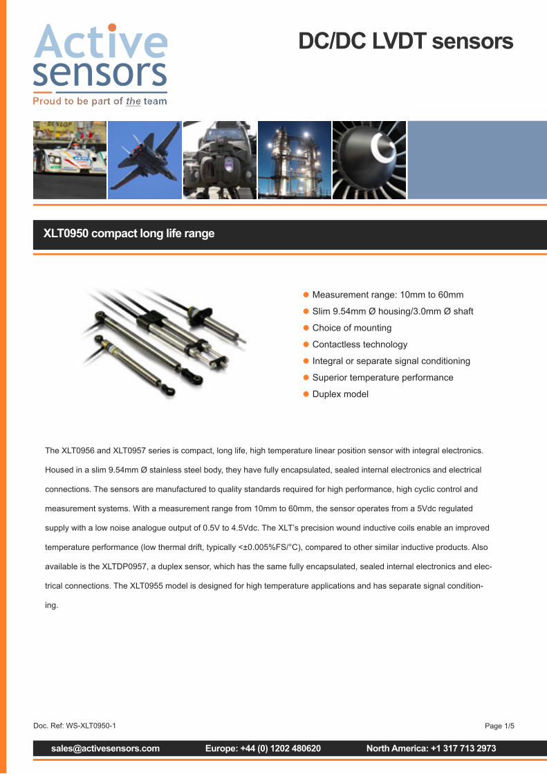
XLT0950 compact long life range
DC/DC LVDT sensors
The XLT0956 and XLT0957 series is compact, long life, high temperature linear position sensor with integral electronics.
Housed in a slim 9.54mm Ø stainless steel body, they have fully encapsulated, sealed internal electronics and electrical
connections. The sensors are manufactured to quality standards required for high performance, high cyclic control and
measurement systems. With a measurement range from 10mm to 60mm, the sensor operates from a 5Vdc regulated
supply with a low noise analogue output of 0.5V to 4.5Vdc. The XLT’s precision wound inductive coils enable an improved
temperature performance (low thermal drift, typically <±0.005%FS/°C), compared to other similar inductive products. Also
available is the XLTDP0957, a duplex sensor, which has the same fully encapsulated, sealed internal electronics and elec-
trical connections. The XLT0955 model is designed for high temperature applications and has separate signal condition-
ing.
• Measurement range: 10mm to 60mm
• Slim 9.54mm Ø housing/3.0mm Ø shaft
• Choice of mounting
• Contactless technology
• Integral or separate signal conditioning
• Superior temperature performance
• Duplex model
[email protected] Europe: +44 (0) 1202 480620 North America: +1 317 713 2973
Page 1/5Doc. Ref: WS-XLT0950-1
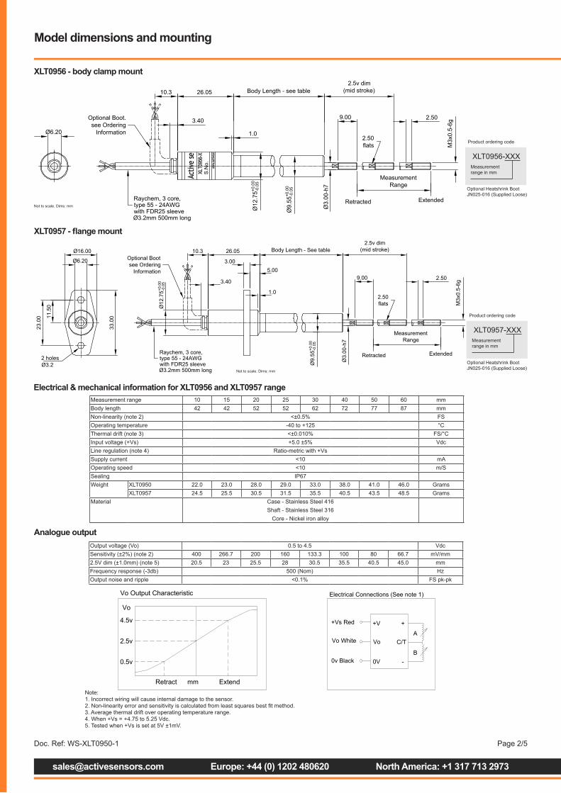
Electrical & mechanical information for XLT0956 and XLT0957 range
XLT0957 - flange mount
[email protected] Europe: +44 (0) 1202 480620 North America: +1 317 713 2973
Page 2/5
Measurement range 10 15 20 25 30 40 50 60 mmBody length 42 42 52 52 62 72 77 87 mmNon-linearity (note 2) <±0.5% FSOperating temperature -40 to +125 °CThermal drift (note 3) <±0.010% FS/°CInput voltage (+Vs) +5.0 ±5% VdcLine regulation (note 4) Ratio-metric with +VsSupply current <10 mAOperating speed <10 m/SSealing IP67Weight XLT0950 22.0 23.0 28.0 29.0 33.0 38.0 41.0 46.0 Grams
XLT0957 24.5 25.5 30.5 31.5 35.5 40.5 43.5 48.5 GramsMaterial Case - Stainless Steel 416
Shaft - Stainless Steel 316Core - Nickel iron alloy
XLT0957-XXXMeasurement range in mm
Product ordering code
Not to scale. Dims: mm
Raychem, 3 core,type 55 - 24AWGwith FDR25 sleeveØ3.2mm 500mm long
Body Length - See table
Ø9.
55+0
.00
-0.0
5
3.40
Ø6.20
Ø12
.75+0
.00
-0.0
5
1.0
5.003.00
26.05
11.5
0
23.0
0
Ø16.00
33.0
0
2 holesØ3.2
10.3Optional Bootsee Ordering
Information
Retracted
2.50flats M
3x0.
5-6g
Ø3.
00-h
7
2.5v dim(mid stroke)
MeasurementRange
Extended
9.00 2.50
Analogue outputOutput voltage (Vo) 0.5 to 4.5 VdcSensitivity (±2%) (note 2) 400 266.7 200 160 133.3 100 80 66.7 mV/mm2.5V dim (±1.0mm) (note 5) 20.5 23 25.5 28 30.5 35.5 40.5 45.0 mmFrequency response (-3db) 500 (Nom) HzOutput noise and ripple <0.1% FS pk-pk
Vo Output Characteristic
0.5v
4.5v
Retract Extendmm
2.5v
Vo
Note 2
Electrical Connections (See note 1)
+Vs Red
Vo White
0v Black
A
B
C/T
-
++V
Vo
0V
Model dimensions and mounting
XLT0956 - body clamp mount
XLT0956-XXXMeasurement range in mm
Product ordering code
Not to scale. Dims: mmRetracted
2.50flats M
3x0.
5-6g
Raychem, 3 core,type 55 - 24AWGwith FDR25 sleeveØ3.2mm 500mm long
Body Length - see table
Ø9.
55+0
.00
-0.0
5
Ø3.
00-h
7
3.40
Ø6.20
Ø12
.75+0
.00
-0.0
5
2.5v dim(mid stroke)
MeasurementRange
Extended
1.0
26.0510.3
Optional Boot.see Ordering
Information
S.N
o.
9.00 2.50
Optional Heatshrink Boot JN025-016 (Supplied Loose)
Optional Heatshrink Boot JN025-016 (Supplied Loose)
Note:1. Incorrect wiring will cause internal damage to the sensor.2. Non-linearity error and sensitivity is calculated from least squares best fit method.3. Average thermal drift over operating temperature range.4. When +Vs = +4.75 to 5.25 Vdc.5. Tested when +Vs is set at 5V ±1mV.
Doc. Ref: WS-XLT0950-1

[email protected] Europe: +44 (0) 1202 480620 North America: +1 317 713 2973
Page 3/5
XLTDP0957 - duplex model
XLTDP0957-060
Product ordering code
Not to scale. Dims: mm
Electrical & mechanical information for XLTDP0957 rangeMeasurement range 60 mmInput voltage (+Vs) 5 ±5% Volts DCSupply current <10 mA dcOutput voltage (Vo) 0.5 to 4.5 Volts DCNon-linearity <±0.5 %Phasing (channel to channel) <1.0 %Thermal drift <±0.01% FS/°COutput load >150 ohmsOutput noise and ripple 0.1% FS (pk-pk)Frequency response (-3dB) 500 (Nom) HzMechanical range Measurement range +1 mmShaft velocity <1000 mm/secOperating temp. range -40° to +125° °CSealing IP66Shaft operating force <100 (typical) gramsMaterial Case - Stainless steel 416
Shaft - Stainless Steel 316
Note:1. Incorrect wiring will cause internal damage to the sensor.
Optional Heatshrink Boot JN025-016 (Supplied Loose)
(See Note 1)XLTDP DC Output Characteristic
mm
Doc. Ref: WS-XLT0950-1
[email protected] Europe: +44 (0) 1202 480620 North America: +1 317 713 2973
Page 4/5
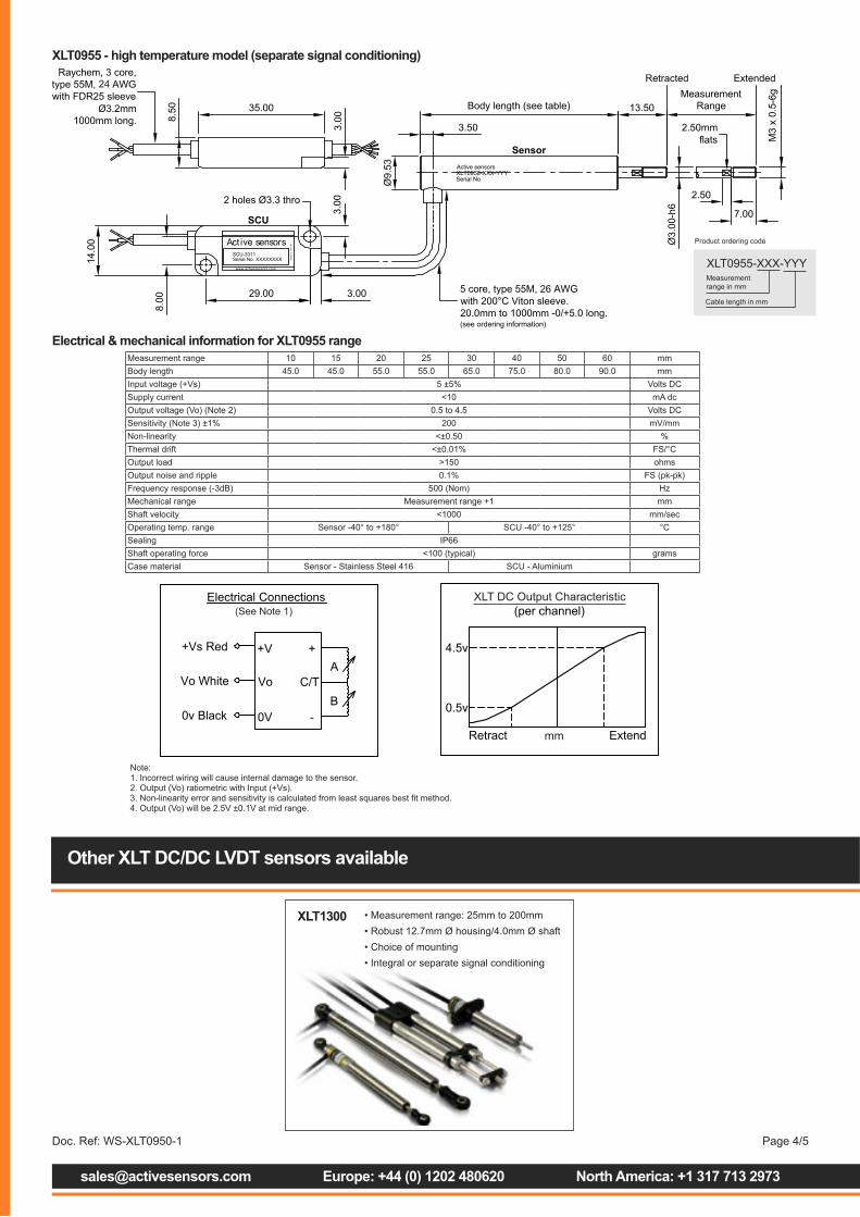
Electrical & mechanical information for XLT0955 range
XLT0955 - high temperature model (separate signal conditioning)
Measurement range 10 15 20 25 30 40 50 60 mmBody length 45.0 45.0 55.0 55.0 65.0 75.0 80.0 90.0 mmInput voltage (+Vs) 5 ±5% Volts DCSupply current <10 mA dcOutput voltage (Vo) (Note 2) 0.5 to 4.5 Volts DCSensitivity (Note 3) ±1% 200 mV/mmNon-linearity <±0.50 %Thermal drift <±0.01% FS/°COutput load >150 ohmsOutput noise and ripple 0.1% FS (pk-pk)Frequency response (-3dB) 500 (Nom) HzMechanical range Measurement range +1 mmShaft velocity <1000 mm/secOperating temp. range Sensor -40° to +180° SCU -40° to +125° °CSealing IP66Shaft operating force <100 (typical) gramsCase material Sensor - Stainless Steel 416 SCU - Aluminium
XLT0955-XXX-YYYMeasurement range in mm
Product ordering code
Cable length in mm
Note:1. Incorrect wiring will cause internal damage to the sensor.2. Output (Vo) ratiometric with Input (+Vs).3. Non-linearity error and sensitivity is calculated from least squares best fit method.4. Output (Vo) will be 2.5V ±0.1V at mid range.
Other XLT DC/DC LVDT sensors available
XLT1300 • Measurement range: 25mm to 200mm• Robust 12.7mm Ø housing/4.0mm Ø shaft • Choice of mounting• Integral or separate signal conditioning
24
(See Note 1)XLT DC Output Characteristic
mm
Doc. Ref: WS-XLT0950-1

Contact details
EuropeActive Sensors Ltd
Unit 12, Wilverley Road
Christchurch, Dorset
BH23 3RU
UK
Tel +44 (0)1202 480620
Fax +44 (0)1202 480664
North AmericaActive Sensors Inc.
8520 Allison Point Blvd Suit 220
Indianapolis
IN 46250
USA
Tel + 317 713 2973
Fax + 317 713 2950
[email protected] Europe: +44 (0) 1202 480620 North America: +1 317 713 2973
Page 5/5Doc. Ref: WS-XLT0950-1
Additional product informationThe information contained in this data sheet on product applications should be used by customers for guidance only. Active Sensors makes no warranty or representation in respect of product fitness or suitability for any particular design application, environment or otherwise except as may subsequently be agreed in the contract for the sale and purchase of products. Additionally, Active Sensors gives no guarantee or warranty for it products in critical control applications, typically in life support systems and the aviation and nuclear industries, where product failure may result in injury, loss of life or catastrophic property damage. Customers should therefore satisfy themselves of the actual performance requirements and subsequently the products suitability for any particular design application and the environment in which the product is to be used. Continual research and development may require change to products and specification without prior notification. © Active Sensors

XLT1320 compact long life range
DC/DC LVDT sensors
The XLT1321 and XLT1325 is a compact, long life, high temperature linear position sensor with integral electronics. It is
housed in a slim 12.70mm Ø stainless steel body and has fully encapsulated, sealed internal electronics and electrical
connections. The sensor is manufactured to quality standards required for high performance, high cyclic control and
measurement systems. With a measurement range from 25mm to 200mm, the sensor operates from 6 to 30Vdc
unregulated supply with a low noise analogue output of 0.5V to 4.5Vdc. The XLT’s precision wound inductive coils enable
an improved temperature performance (low thermal drift, typically <±0.005%FS/°C), compared to other similar inductive
products. Also available in the XLT1328 sensor which is designed for high temperature applications and has separate
• Measurement range: 25mm (1”) to 200mm (8”)
• Robust 12.7mm Ø housing/4.0mm Ø shaft
• Choice of mounting
• Contactless technology
• Integral or separate signal conditioning
• Superior temperature performance
[email protected] Europe: +44 (0) 1202 480620 North America: +1 317 713 2973
Page 1/5Doc. Ref: WS-XLT1300-1
[email protected] Europe: +44 (0) 1202 480620 North America: +1 317 713 2973
Page 2/5
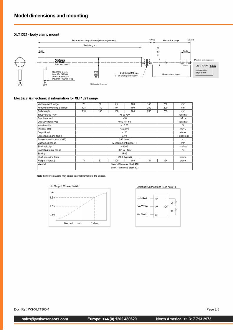
Electrical & mechanical information for XLT1321 rangeMeasurement range 25 50 75 100 150 200 mmRetracted mounting distance 124 149 174 199 249 299 mmBody length 110 135 160 185 235 285 mmInput voltage (+Vs) +6 to +30 Volts DCSupply current <10 mA dcOutput voltage (Vo) 0.50 to 4.50 Volts DCNon-linearity <±0.30 %Thermal drift <±0.01% FS/°COutput load >150 ohmsOutput noise and ripple 0.1% FS (pk-pk)Frequency response (-3dB) 250 (Nom) HzMechanical range Measurement range +1 mmShaft velocity <1000 mm/secOperating temp. range -40° to +125° °CSealing IP66Shaft operating force <100 (typical) gramsWeight (approx.) 71 83 105 108 141 166 gramsMaterial Case - Stainless Steel 410
Shaft - Stainless Steel 303
Vo Output Characteristic
0.5v
4.5v
Retract Extendmm
2.5v
Vo
Note 2
Electrical Connections (See note 1)
+Vs Red
Vo White
0v Black
A
B
C/T
-
++V
Vo
0V
Model dimensions and mounting
XLT1321 - body clamp mount
XLT1321-XXXMeasurement range in mm
Product ordering code
Not to scale. Dims: mm
Raychem, 3 core,
with FDR25 sleevetype 55 - 24AWG
Ø3.2mm 1000mm long
M4x
0.7-
6g
Body length
Measurement range
Mechanical rangeRetracted mounting distance (±1mm adjustment) Retract Extend
Ø12
.70
12.6
5
9.25
2 off S/steel M4 nuts& 1 off shakeproof washer
13.00
S.No. XXXXXXXX
Note 1: Incorrect wiring may cause internal damage to the sensor.
Doc. Ref: WS-XLT1300-1

XLT1325 - rod end mount
[email protected] Europe: +44 (0) 1202 480620 North America: +1 317 713 2973
Page 3/5
XLT1325-XXXMeasurement range in mm
Product ordering code
Not to scale. Dims: mm
Raychem, 3 core,
with FDR25 sleevetype 55 - 24AWG
Ø3.2mm 1000mm long
Spherical bearingmounting holeØ5 (+0.05/-0.00)fitted both ends
6.00
24°
8.00
Ø4-
h713.00
Body length
Measurement range
Mechanical rangeRetracted mounting distance (±1mm adjustment) Retract Extend
Ø12
.70
12.6
5
S.No. XXXXXXXX
Electrical & mechanical information for XLT1325 rangeMeasurement range 25 50 75 100 150 200 mmRetracted mounting distance 173 198 223 248 298 348 mmBody length 143 168 193 218 268 318 mmInput voltage (+Vs) +6 to +30 Volts DCLine regulation ( Vo) <0.025%FS (+Vs = +6 to +30Vdc)Supply current <10 mA dcOutput voltage (Vo) 0.50 to 4.50 Volts DCSensitivity (Note 3) ±1% 160 80 53.3 40 26.7 20 mV/mmNon-linearity (Note 3) <±0.30 %Thermal drift <±0.010% FS/°COutput load >150 ohmsOutput noise and ripple 0.05% FS (pk-pk)Frequency response (-3dB) 500 (Nom) HzMechanical range Measurement range +1 mmShaft velocity <1000 mm/secOperating temp. range -40° to +125° °CSealing IP66Shaft operating force <100 (typical) gramsMaterial Case - Stainless Steel 410
Shaft - Stainless Steel 303
Vo Output Characteristic
0.5v
4.5v
Retract Extendmm
2.5v
Vo
Note 2
Electrical Connections (See note 1)
+Vs Red
Vo White
0v Black
A
B
C/T
-
++V
Vo
0V
Note 1: Incorrect wiring may cause internal damage to the sensor.Note 2: Sensor calibrated to 2.5v±0.01v at Retracted mounted distance + (Measurement range/2)Note 3: Non-linearity error and sensitivity is calculated from least squares best fit method.
Doc. Ref: WS-XLT1300-1

[email protected] Europe: +44 (0) 1202 480620 North America: +1 317 713 2973
Page 4/5
XLT1328 - high temperature model (separate signal conditioning)
Not to scale. Dims: mm
Electrical & mechanical information for XLT1328 rangeMeasurement range 25 50 75 100 150 200 mmBody length 80.0 105.0 130.0 155.0 205.0 255.0 mmInput voltage (+Vs) 5 ±5% Volts DCSupply current <10 mA dcOutput voltage (Vo) (Note 2) 0.50 to 4.50 Volts DCNon-linearity <±0.50 %Thermal drift <±0.010% FS/°COutput load >150 ohmsOutput noise and ripple 0.1% FS (pk-pk)Frequency response (-3dB) 500 (Nom) HzOperating temp. range Sensor - -40° to +180° SCU - -40° to +125° °CSealing IP66Material Sensor - Stainless Steel 410 SCU - Aluminium
Vo Output Characteristic
0.5v
4.5v
Retract Extendmm
2.5v
Vo
Note 2
Electrical Connections (See note 1)
+Vs Red
Vo White
0v Black
A
B
C/T
-
++V
Vo
0V
Note 1: Incorrect wiring may cause internal damage to the sensor.Note 2: Output (Vo) ratiometric with input (+Vs)
Other XLT DC/DC LVDT sensors available
XLT0950 • Measurement range: 10mm to 60mm• Slim 9.54mm Ø housing/3.0mm Ø shaft • Choice of mounting• Integral or separate signal conditioning
24
XLT1328-XXX-YYYMeasurement range in mm
Product ordering code
Cable length in mm
Doc. Ref: WS-XLT1300-1
Contact details
EuropeActive Sensors Ltd
Unit 12, Wilverley Road
Christchurch, Dorset
BH23 3RU
UK
Tel +44 (0)1202 480620
Fax +44 (0)1202 480664
North AmericaActive Sensors Inc.
8520 Allison Point Blvd Suit 220
Indianapolis
IN 46250
USA
Tel + 317 713 2973
Fax + 317 713 2950
Doc. Ref: WS-XLT1300-1
Additional product informationThe information contained in this data sheet on product applications should be used by customers for guidance only. Active Sensors makes no warranty or representation in respect of product fitness or suitability for any particular design application, environment or otherwise except as may subsequently be agreed in the contract for the sale and purchase of products. Additionally, Active Sensors gives no guarantee or warranty for it products in critical control applications, typically in life support systems and the aviation and nuclear industries, where product failure may result in injury, loss of life or catastrophic property damage. Customers should therefore satisfy themselves of the actual performance requirements and subsequently the products suitability for any particular design application and the environment in which the product is to be used. Continual research and development may require change to products and specification without prior notification. © Active Sensors
[email protected] Europe: +44 (0) 1202 480620 North America: +1 317 713 2973
Page 5/5

XLT1321 and XLT1325 DC/DC linear position sensor technical information
DC/DC LVDT sensors
The sensors input circuitry contains its own linear regulator system that incorporates several features which make it ideal for use
in automotive battery-powered systems. In addition to the normal features associated with sensors that contain voltage regulation,
such as current limiting and thermal limiting, the sensor is protected against reverse input voltage. The input of the sensor will
withstand reverse voltages of 50V. Current flow into the device will be limited to less than 6mA (typically less than 100µA) and no
negative voltage will appear at the output, as the sensor protects both itself and the load and therefore provides protection against
reverse connected batteries.
The XLT 1321/25 linear inductive sensor series have internal thermal limiting designed to protect the sensor during overload
conditions. For continuous normal conditions the maximum temperature rating of 125°C must not be exceeded. It is important
to give careful consideration to the thermal resistance from sensor case to ambient during high temperature operation and any
additional heat sources mounted nearby must also be considered.
The output circuit contains a high output drive CMOS operational amplifier with a high tolerance to resistive (RL) and capacitive
(CL) loads and is therefore suitable for line driver applications as it possess a 25mA dc output drive capability The output amplifier
is stable with capacitive loads up to 780pF. When driving higher capacitive loads, a low value isolation resistor (39O) connected
in series with the output improves the transient response and the phase margin. The lead length between the sensor and the dc
power source and the signal output (Vo) and the data aquisition system should be kept below 10m.
• Measurement range: 25mm (1”) to 200mm (8”)
• Contactless technology
• Operation up to +125°C
• 6V to 30Vdc input
• 0.5V to 4.5Vdc output
[email protected] Europe: +44 (0) 1202 480620 North America: +1 317 713 2973
Page 1/5
Internal circuit features
RED (+Vs): A dc voltage is applied to this wire to power the internal signal conditioning electronics of the sensor. The supply can
be a regulated or unregulated voltage supply, providing the level does not exceed that stated in the operating voltage range of the
sensor. Permanent damage may result if the supply voltage exceeds the absolute maximum levels. The voltage supply must be
capable of supplying 10mA of current, to power the internal electronics plus the maximum output current (Iout) supplied to the load.
Wire functions
(See datasheets for mechanical specification)
Doc. Ref: WS-XLT1300TI-1

[email protected] Europe: +44 (0) 1202 480620 North America: +1 317 713 2973
Page 2/5
BLACK (0V): This wire is connected to the supply return, 0v or ground of the sensor’s external power supply system. The black
wire is isolated from the sensors conducting case.
WHITE (Vo): This wire provides a low noise output voltage signal (0.5V to 4.5V) from the sensors output amplifier and is referenced
to the sensors black terminal wire. The resistive (RL) and/or capacitive (CL) loads connected to this terminal and the corresponding
output current (Iout), must not exceed the limit specified.
Absolute maximum ratings
Permanent damage may occur if the XLT1321/25 sensor is exposed to any conditions outside its absolute maximum rating.
Supply voltage (+Vs) +50V
Operating temperature range -40°C to +125°C (Note 1)
Storage temperature range -40°C to +125°C
Maximum power dissipation 1W
Output current (Iout) <30mA (Note 2)
Operating specification
TA= +25°C, +Vs= +12Vdc, RL= 10KΩ, CL= 0pF unless otherwise stated.
♦ see operating characteristics
Parameter Symbols Conditions Min Typ Max Units
Input voltage +Vs 4.75 30 Vdc
Input current Is ♦ +Vs = +4.75 to +30Vdc 7 10 mA
Output voltage Vo 0.5 4.50 Vdc
Sensitivity tolerance (±) Note 3, 4 1.0 %
Output current Iout ♦ see derating graph 25 mA
Output resistance Up to 10Khz 0.10 ohms
Line regulation Vol/ +Vs ♦ +Vs = +6v to +30Vdc 0.01 %FS
Output noise/ripple ♦ RL=10K, CL=0pF 0.10 %FS p-p
Power on settlement ♦ within 0.25%FS of final output 200 mS
Under voltage cutout ♦ RL=100K 4.0 Vdc
Parameter Symbols Conditions Min Typ Max Units
Measurement range 25 200 mm
Non-linearity (±) Note 4 0.2 0.3 %FS
Resolution INFINITE
Operating temperature t°C ♦ Note 1 -40 +125 °C
Thermal drift (±) ♦ Note 5 0.005 0.010 %FS/°C
Frequency response Bw ♦ Note 6 500 Hz
Performance specification
Parameter Symbols Conditions Min Typ Max Units
Load resistance RL 180 ohms
Load capacitance CL 780 pF
Lead length 10 m
Load specification
Doc. Ref: WS-XLT1300TI-1
[email protected] Europe: +44 (0) 1202 480620 North America: +1 317 713 2973
Page 3/5
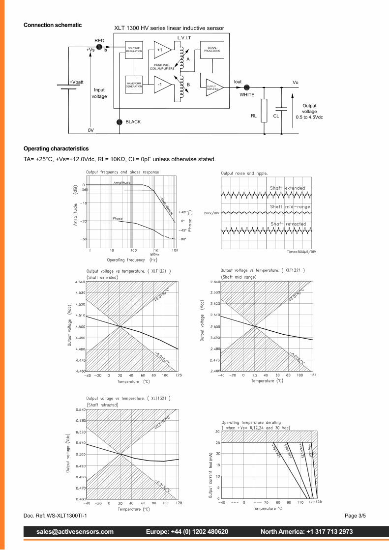
Connection schematic
Operating characteristics
TA= +25°C, +Vs=+12.0Vdc, RL= 10KΩ, CL= 0pF unless otherwise stated.
Doc. Ref: WS-XLT1300TI-1

[email protected] Europe: +44 (0) 1202 480620 North America: +1 317 713 2973
Page 4/5
Note 1: when +Vs=+6Vdc and RL>100KΩ, otherwise see operating temperature derating characteristics.
Note 2: The output current (Iout = Vo/RL) can reach 30mA as long as the maximum power dissipation of the sensor is not
exceeded.
Note 3: Ideal sensitivity (mV/mm) is calculated from the ideal span voltage of 4000mV (4.5-0.5Vdc), divided by the sensor
measurement range in mm.
Note 4: Non-linearity error and sensitivity is calculated from the least squares best fit method.
Note 5: Average thermal drift over –40 to +125°C temperature range.
Note 6: -3dB Bandwidth with a 1st order (-20dB/decade) roll-off.
Notes
Doc. Ref: WS-XLT1300TI-1
Contact details
EuropeActive Sensors Ltd
Unit 12, Wilverley Road
Christchurch, Dorset
BH23 3RU
UK
Tel +44 (0)1202 480620
Fax +44 (0)1202 480664
North AmericaActive Sensors Inc.
8520 Allison Point Blvd Suit 220
Indianapolis
IN 46250
USA
Tel + 317 713 2973
Fax + 317 713 2950
Doc. Ref: WS-XLT1300TI-1
Additional product informationThe information contained in this data sheet on product applications should be used by customers for guidance only. Active Sensors makes no warranty or representation in respect of product fitness or suitability for any particular design application, environment or otherwise except as may subsequently be agreed in the contract for the sale and purchase of products. Additionally, Active Sensors gives no guarantee or warranty for it products in critical control applications, typically in life support systems and the aviation and nuclear industries, where product failure may result in injury, loss of life or catastrophic property damage. Customers should therefore satisfy themselves of the actual performance requirements and subsequently the products suitability for any particular design application and the environment in which the product is to be used. Continual research and development may require change to products and specification without prior notification. © Active Sensors
[email protected] Europe: +44 (0) 1202 480620 North America: +1 317 713 2973
Page 5/5