dcl sis (sales information service) 2: profiles 2 2–2 bosch rexroth corporation aluminum framing...
TRANSCRIPT

We reserve the right to make technical changes at any time without notice. Page 1
Electric Drivesand Controls Hydraulics
Linear Motion andAssembly Technologies Pneumatics ServiceIndustrial
HydraulicsElectric Drivesand Controls
Linear Motion andAssembly Technologies
ServiceAutomation
MobileHydraulicsPneumatics
DCL SIS (Sales Information Service)Date:Issued by:
Bosch Rexroth Corporation • 816 East Third St., Buchanan, MI 49107 • 269-695-0151 08-08-2009
PB-MGE01-09 USProduct Bulletin- Aluminum Structural Framing
Updates and Corrections to Catalog Version 6.0
Product additions and improvements to our aluminum structural framing system have created some significant changes to the current catalog. The following list reflects the updates and corrections that we have made to version 6.0 of the catalog. Please refer to the new pages attached in this product bulletin for the updated information and make a note of them in your catalog. A pdf of this update can also be downloaded from our web site at:
www.boschrexroth-us.com/BRLcatalogs and click on Manuals and Product Updates.
These updates will be included with the next printing of Version 6.5 of the catalog which should be available early in 2010.
Please contact Bosch Rexroth if you require additional information or assistance.
Section 2: Profiles
Page 2-2: A new profile, 40x80 3SA, has been added and Techni-cal Specifications have been updated for 40x40 2S, 40x40 2SA and 40x40 3S.
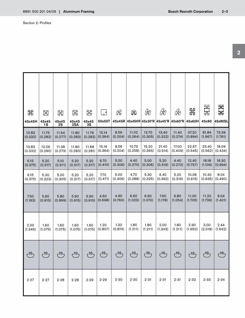
Page 2-3: Technical Specifications for 45x90SL have been updated.
Page 2-4: Technical Specifications for 45x90 2S and 45x90 3VS have been corrected.
Page 2-6: New profiles, 15x120 and 15x180, have been added.
Page 2-7: Technical Specifications have been added for 22.5x30F profile.
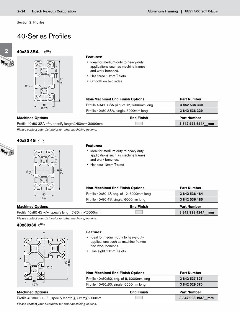
Page 2-24: The new 40x80 3SA profile has been added.
Page 2-29: Updates have been made to 50x50T package and single profile part numbers and lengths.
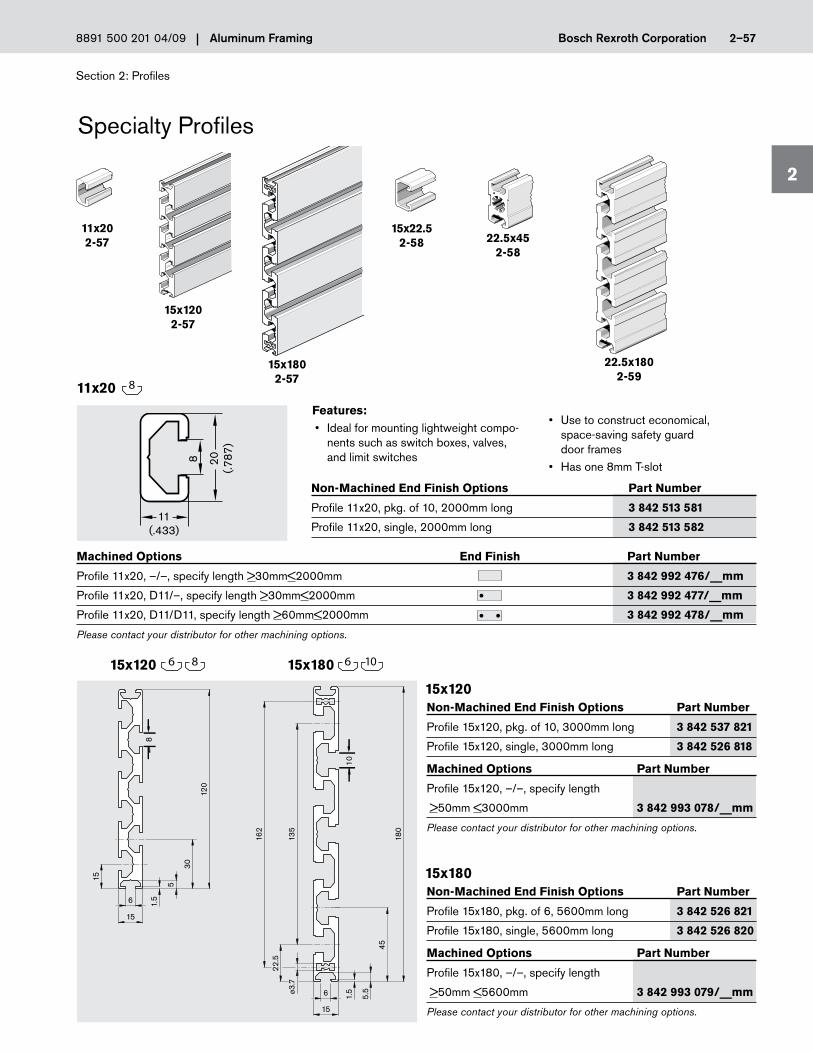
Page 2-57: 15x120 and 15x180 specialty profiles have been added to the product offering. New Profiles

We reserve the right to make technical changes at any time without notice. Page 2
Electric Drivesand Controls Hydraulics
Linear Motion andAssembly Technologies Pneumatics Service
PB-MGE01-09 US (cont’d)
Section 3: Profile Connectors
Page 3-17: 9.8mm designLINE access hole covers now carry part num-ber of 3 842 538 567.
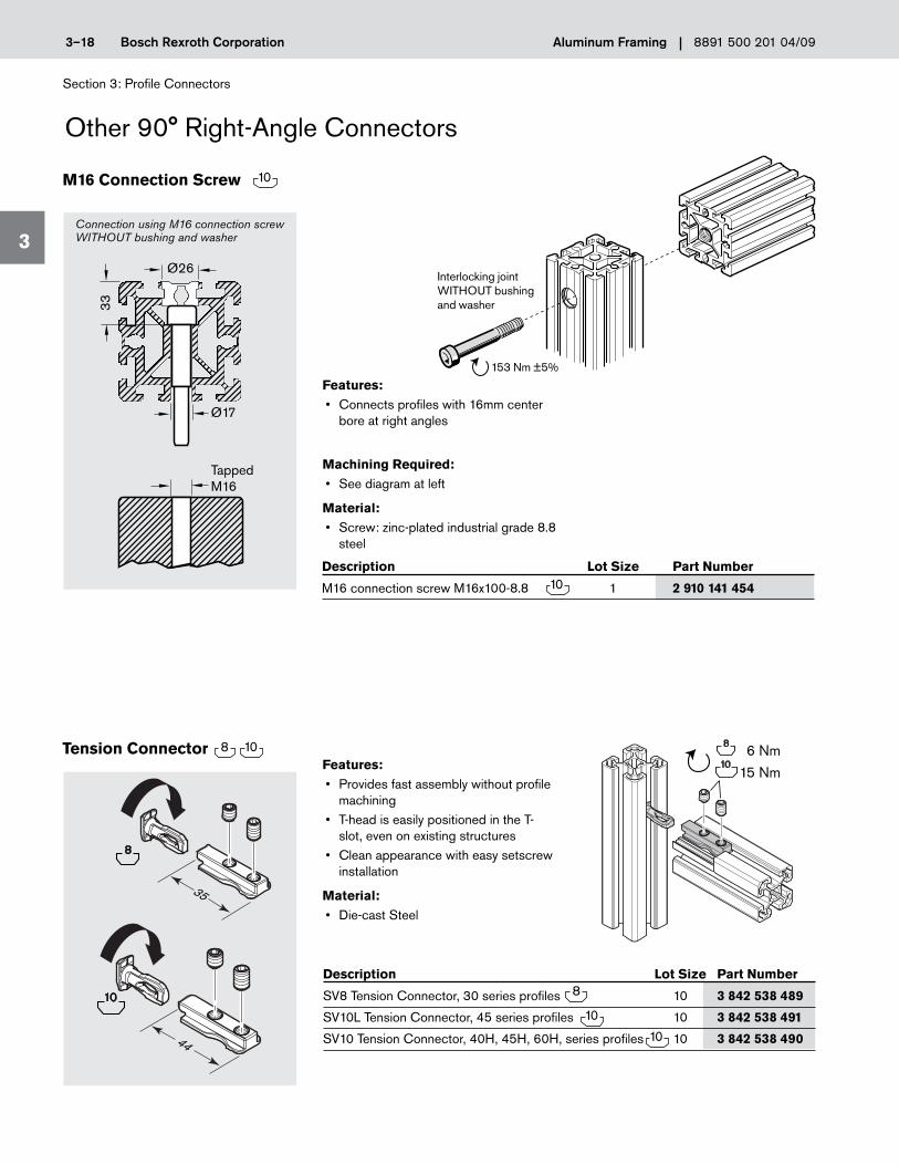
Page 3-18: Torque specs have been added for the M16 connection screw and a NEW Tension Connector has been added to the page.
Page 3-29: The part number for the 45x45 designLine multi-angle conn. kit, lockable is now 3 842 538 687. Also, the description on part number 3 842 502 685 is now, 45x60 multi-angle connector kit.
Page 3-32: The description on part number 3 842 529 020 is now, 40mm adjustable angle gusset only. The part number 3 842 551 580 has been changed to 3 842 521 580
Page 3-33: 80 and 100 series Joining Plates are no longer available and references to them have been removed from the page.
Section 4: Fasteners
Page 4-1: T-Nut Tightening Torque values have been reviewed and up-dated as required.
Page 4-2: Stainless steel T-Nut Tightening Torque values have been reviewed and updated as required.
Page 4-5: T-block Tightening Torque values have been reviewed and updated as required.
Page 4-6: Swivel-in T-block Tightening Torque values have been reviewed and updated as required.
Section 5: Door and Door ComponentsPage 5-6: Fmax load rating has been added to Ball-Bearing Carriage.
Section 6: EcoSafe™ Guarding and Machine/Safety Enclosures
Page 6-4: The 19mm T-bolt kit (#8 981 021 343) has been replaced with a 24mm T-bolt kit, part number 8 981 021 344.
Page 6-18: In the lower Frame Profile dimension drawing the S8x25 and M8x16 screws are now in the correct positions.
Page 6-23: The formula in the Assembly Note has been corrected and made easier to follow.
Section 7: Floor to Frame Elements
Page 7-8: Under Caster Features, the third bullet point has been removed.
Page 7-14: The Foundation Bracket dimension drawings are now shown in the correct orientation.
86 Nm
15 Nm10
New Tension Connector
2.5 Nm
2.5 Nm
5 Nm
10 Nm
25 Nm

We reserve the right to make technical changes at any time without notice. Page 3
Electric Drivesand Controls Hydraulics
Linear Motion andAssembly Technologies Pneumatics Service
PB-MGE01-09 US (cont’d)
Section 10: EcoFlow™ Conveyor and Transport ComponentsPage 10-7: The dimension (Pallet Width–5) in the Assembly Note has been corrected to Pallet Width+5.
Page 10-12: The 24mm Forstner bit is no longer available and the item has been removed from the page. Also, the material for the roller ball is now galvanized steel.
Section 11: Ergonomic Workplace Equipment
Page 11-29: Item A, Bottle Holder, now includes mounting hardware and carries a new part number of 3 842 540 429.
Page 11-38: The 8mm T-slot symbol has been removed from the Fixture Plate heading. While fixture plate uses 8mm T-nuts and T-bolts it is not compatible with other 8mm components such as cover strip. This is now noted in the 5th bullet point.
Section 12: Accessories
Page 12-4: Both Movable Swivel bracket kits have updated part num-bers. Kit A is now part number 3 842 538 275, Kit B is 3 842 538 276.
Section 15: Tools
Page 15-3: The 10mm Miter Drilling Jig part number has been corrected to 3 842 516 731
Section 16: Engineering Data and Specifications
Page 16-0: The US Equivalent material designation and material number has changed from 6063 T6 in the catalog to AW-6063-T66.
Page 16-6: The three profiles at the bottom of the catalog page, (30x30, 40x40, 45x45 and related information) have been removed and replaced with the load carrying capacity data for Quick Connectors and Tension Connectors.
Page 16-7: The load carrying capacity for the Radius Compensator has been added to the bottom of the Corner Cube data chart.
Page 16-8: Some of the special characters on the bending deflection page printed improperly which made the formulas hard to follow. This has been corrected on the updated page.
Fmax
Mmax
Mmax
L
F
F
F
ff
f
1
2
3

Section 2: Profiles
2
Bosch Rexroth Corporation Aluminum Framing 2–2 8891 500 201 04/09
Moment of inertia
Section modulus
Profile surface
Weight (Mass)
T-slot
Page
A[cm2](in2)
m[kg/m](lbs/ft)
[mm]
Wx[cm3](in3)
Wy[cm3](in3)
Iy[cm4](in4)
Ix[cm4](in4)
45x45
11.00
11.00
4.89
4.89
5.70
1.50
2-26
(0.264)
(0.264)
(0.298)
(0.298)
(0.884)
(1.009)
8.10
7.60
4.00
3.60
5.50
1.50
2-23
40x40HR
(0.194)
(0.182)
(0.243)
(0.219)
(0.853)
(1.009)
96.60
96.60
24.10
24.10
15.40
4.10
2-24
40x80x80
(2.319)
(2.319)
(1.469)
(1.469)
(2.388)
(2.757)
466.70
37.20
58.30
18.60
20.50
5.50
2-25
203.20
27.80
33.90
13.90
15.50
4.20
2-25
63.40
17.30
15.90
8.70
9.90
2.70
2-23
40x80 40x803SA
40x160
40x120
(1.522)
(0.417)
(0.974)
(0.532)
(1.533)
(1.815)
67.81
18.99
16.95
9.50
10.56
2.85
2-24
(1.627)
(0.456)
(1.034)
(0.580)
(1.637)
(1.918)
(4.877)
(0.667)
(2.075)
(0.851)
(2.405)
(2.824)
(11.219)
(0.887)
(3.551)
(1.137)
(3.180)
(3.696)
7.20
7.20
3.60
3.60
5.00
1.30
2-22
(0.175)
(0.175)
(0.219)
(0.219)
(0.776)
(0.873)
40x40R
40x402S
40x402SA
40x403S
10.34
9.08
5.17
4.54
5.96
1.61
2-21
(0.248)
(0.218)
(0.315)
(0.277)
(0.924)
(1.083)
9.71
9.71
4.85
4.85
5.36
1.61
2-21
(0.233)
(0.233)
(0.295)
(0.295)
(0.924)
(1.083)
9.07
9.70
4.53
4.85
5.79
1.56
2-22
(0.218)
(0.233)
(0.276)
(0.235)
(0.897)
(1.050)
65.17
19.05
16.29
9.91
10.39
2.80
2-24
(1.564)
(0.457)
(0.994)
(0.605)
(1.610)
(1.882)
40x804S
Technical Specifications
Section 2: Profiles
2
Bosch Rexroth CorporationAluminum Framing 2–38891 500 201 04/09
50x50T 45x45R 45x45HR
15.14
15.16
6.70
7.70
4.60
1.20
2-29
11.02
10.73
4.40
4.70
6.60
1.80
2-30
8.56
8.56
5.00
5.00
4.90
1.30
2-30
(0.204)
(0.204)
(0.306)
(0.306)
(0.760)
(0.874)
(0.364)
(0.364)
(0.410)
(0.471)
(0.698)
(0.807)
(0.264)
(0.258)
(0.270)
(0.288)
(1.023)
(1.211)
45x60H 45x90SL45x9045x30ºR 45x45ºR 45x60ºR
37.20
22.67
12.40
10.08
11.00
2.90
2-32
81.84
23.40
18.18
10.40
11.20
3.00
2-33
12.70
15.20
5.00
5.30
6.90
1.80
2-31
13.40
21.40
5.20
6.40
7.60
2.00
2-31
11.40
17.00
4.40
5.20
6.80
1.80
2-31
73.36
18.09
16.30
8.04
9.04
2.44
2-34
(0.305)
(0.365)
(0.306)
(0.325)
(1.070)
(1.211)
(0.322)
(0.514)
(0.319)
(0.392)
(1.178)
(1.343)
(0.274)
(0.409)
(0.270)
(0.319)
(1.054)
(1.211)
(0.894)
(0.545)
(0.757)
(0.615)
(1.705)
(1.950)
(1.967)
(0.562)
(1.109)
(0.635)
(1.736)
(2.018)
(1.761)
(0.434)
(0.994)
(0.490)
(1.401)
(1.642)
13.83
13.83
6.15
6.15
7.50
2.00
2-27
45x45H
(0.332)
(0.332)
(0.375)
(0.375)
(1.163)
(1.345)
45x45 1S
45x45 2S
45x45 2SA
45x45 3S
11.75
12.06
5.20
5.30
5.90
1.60
2-27
(0.282)
(0.290)
(0.317)
(0.323)
(0.915)
(1.075)
11.54
11.38
5.10
5.00
5.80
1.60
2-28
(0.277)
(0.273)
(0.311)
(0.305)
(0.899)
(1.075)
11.80
11.80
5.20
5.20
5.90
1.60
2-28
(0.283)
(0.283)
(0.317)
(0.317)
(0.915)
(1.075)
11.79
11.68
5.20
5.20
5.90
1.60
2-29
(0.283)
(0.281)
(0.317)
(0.317)
(0.915)
(1.075)

Section 2: Profiles
2
Bosch Rexroth Corporation Aluminum Framing 2–4 8891 500 201 04/09
Technical Specifications
60x90H
212.44
88.53
47.21
29.51
25.30
6.80
2-45
(5.105)
(2.127)
(2.881)
(1.801)
(3.922)
(4.573)
Moment of inertia
Section modulus
Profile surface
Weight (Mass)
T-slot
Page
A[cm2](in2)
m[kg/m](lbs/ft)
[mm]
Wx[cm3](in3)
Wy[cm3](in3)
Iy[cm4](in4)
Ix[cm4](in4)
60x60 60x60H
32.41
32.41
10.80
10.80
9.60
2.60
2-43
52.20
52.20
17.40
17.40
14.39
3.89
2-44
(0.779)
(0.779)
(0.659)
(0.659)
(1.488)
(1.749)
(1.254)
(1.254)
(1.062)
(1.062)
(2.230)
(2.616)
540.00
64.20
72.00
25.70
25.50
6.90
2-42
50x150
(12.979)
(1.543)
(4.393)
(1.568)
(3.952)
(4.641)
45x180H
766.67
57.28
85.19
25.46
25.50
6.90
2-38
(18.423)
(1.376)
(5.199)
(1.554)
(3.953)
(4.640)
(0.512)
(0.512)
(0.524)
(0.524)
(1.442)
(1.681)
50x50
21.20
21.20
8.50
8.50
9.30
2.50
2-40
162.80
42.60
32.60
17.00
17.20
4.60
2-41
50x100
(3.924)
(1.019)
(1.987)
(1.040)
(2.668)
(3.092)
45x270H
3962.00
118.00
300.20
61.50
61.80
16.70
2-39
(95.207)
(2.836)
(18.387)
(3.767)
(9.579)
(11.231)
45x90x90
151.13
151.13
29.10
29.10
21.00
5.67
2-37
(3.631)
(3.631)
(1.776)
(1.776)
(3.255)
(3.810)
45x90H
124.62
32.76
27.69
14.56
15.37
4.15
2-36
(2.995)
(0.787)
(1.690)
(0.889)
(2.382)
(2.791)
87.20
25.21
38.80
5.60
11.82
3.2
2-35
(2.093)
(0.605)
(2.367)
(0.342)
(1.832)
(2.154)
45x90 2S
85.61
26.89
38.05
5.98
12.00
3.24
2-34
(2.055)
(0.645)
(2.32)
(0.365)
(1.86)
(0.022)
45x90 3VS

Section 2: Profiles
2
Bosch Rexroth Corporation Aluminum Framing 2–6 8891 500 201 04/09
Technical Specifications
Moment of inertia
Section modulus
Profile surface
Weight (Mass)
T-slot
Page
A[cm2](in2)
m[kg/m](lbs/ft)
[mm]
Wx[cm3](in3)
Wy[cm3](in3)
Iy[cm4](in4)
Ix[cm4](in4)
2.48
2.92
1.57
1.83
3.16
0.85
6-12
30x30WG40
(0.060)
(0.070)
(0.096)
(0.112)
(0.490)
(0.574)
10.33
5.60
4.23
3.73
4.38
1.23
5-6–
11-28
C30x45
(0.248)
(0.135)
(0.258)
(0.228)
(0.679)
(0.827)
581.01
11.80
64.56
10.47
21.60
5.80
2-59
22.5x180
(13.961)
(0.284)
(3.939)
(0.639)
(3.348)
(3.901)
2.57
3.01
1.64
1.92
3.19
0.86
6-11
6.98
4.11
4.33
1.82
4.49
1.21
6-12
7.00
4.25
4.30
1.80
4.52
1.22
6-11
30x30WG30
30x45WG40
30x45WG30
(0.062)
(0.072)
(0.100)
(0.118)
(0.494)
(0.579)
(0.168)
(0.099)
(0.265)
(0.111)
(0.696)
(0.814)
(0.168)
(0.102)
(0.262)
(0.110)
(0.701)
(0.820)
7.11
2.91
3.16
2.59
4.60
1.30
2-58
22.5x45
(0.171)
(0.070)
(0.193)
(0.158)
(0.713)
(0.874)
0.81
0.34
0.90
0.60
1.20
0.30
2-58
15x22.5
(0.019)
(0.008)
(0.055)
(0.037)
(0.186)
(0.202)
0.52
0.13
0.70
0.30
1.00
0.30
2-57
11x20
(0.012)
(0.002)
(0.043)
(0.018)
(0.155)
(0.202)
100X200
2133.10
602.10
213.30
120.40
54.00
14.60
2-56
(51.442)
(14.520)
(12.992)
(7.368)
(8.377)
(9.815)
318.30
318.30
63.70
63.70
29.90
8.10
2-55
100x100
(7.639)
(7.639)
(3.896)
(3.896)
(4.637)
(5.449)
15x180
303.50
3.14
n.a.
n.a.
11.64
3.14
2-57
(7.284)
(0.075)
(1.804)
(2.113)
110.4
2.16
18.4
2.74
9.00
2.43
2-57
15x120
(2.650)
(0.052)
(11.224)
(0.167)
(1.395)
(1.635)
6
8
6
* Specialty profile. Not designed for structural support.

Section 2: Profiles
2
Bosch Rexroth CorporationAluminum Framing 2–78891 500 201 04/09
* Specialty profile. Not designed for structural support.
22.5x30F
12.50
10.70
4.50
4.50
6.40
1.70
10-5
EcoFlowRollerProfile
(0.300)
(0.257)
(0.276)
(0.276)
(0.992)
(1.143)
1.68
2.97
1.49
1.98
3.20
0.86
6-18
(0.040)
(0.071)
(0.091)
(0.121)
(0.496)
(0.579)
4.50
11.90
5.30
1.40
10-13
45x30RP
(0.108)
(0.286)
(0.822)
(0.942)
n. a.
n. a.
1.16
5.88
1.08
2.94
5.10
1.70
14-5-
14-11
9.45
75.92
7.02
19.53
12.90
3.50
14-12-
14-19
31.85
107.93
23.95
35.98
16.60
4.50
14-20-
14-29
4.59
68.07
3.65
15.13
8.00
2.20
14-5-
14-9
LF6S LF12S LF20S26x90
(0.028)
(0.141)
(0.066)
(0.180)
(0.791)
(1.143)
(0.227)
(1.824)
(0.430)
(1.196)
(2.000)
(2.354)
(0.765)
(2.594)
(1.467)
(2.204)
(2.573)
(3.026)
(0.110)
(1.636)
(0.224)
(0.927)
(1.240)
(1.480)
90.30
9.65
18.00
6.40
9.68
2.61
11-40
30x100End
(2.170)
(0.232)
(1.103)
(0.392)
(1.500)
(1.755)
8.85
6.95
3.18
2.32
4.47
1.20
11-25
9.60
13.30
3.80
6.50
5.40
1.50
10-13
15.20
16.90
5.30
7.50
6.90
1.90
10-13
49.50
25.80
12.10
11.50
10.40
2.80
10-13
2.51
2.04
*
*
2.01
*
11-12
45x45T15x3045x45RP
45x50RP
45x75SP2/B
(0.213)
(0.167)
(0.195)
(0.142)
(0.693)
(0.807)
(0.231)
(0.320)
(0.233)
(0.398)
(0.837)
(1.009)
(0.365)
(0.406)
(0.325)
(0.459)
(1.070)
(1.278)
(1.189)
(0.620)
(0.741)
(0.704)
(1.612)
(1.883)
(0.060)
(0.049)
(0.312)
88.80
9.20
17.80
6.00
9.73
2.63
11-40
30x100Center
(2.134)
(0.221)
(1.090)
(0.368)
(1.508)
(1.769)
Section 2: Profiles
2
Bosch Rexroth Corporation Aluminum Framing 2–24 8891 500 201 04/09
40-Series Profiles
Features:• Idealformedium-dutytoheavy-duty
applications such as machine frames and work benches.
• Haseight10mmT-slots
Non-Machined End Finish Options Part Number
Profile 40x80x80, pkg. of 8, 6000mm long 3 842 537 827
Profile 40x80x80, single, 6000mm long 3 842 529 370
Machined Options End Finish Part Number
Profile 40x80x80, –/–, specify length >30mm<6000mm 3 842 993 193/__mm
Please contact your distributor for other machining options.
40x80x80
80
(3.1
5)
40(1.57)
X
Y
Ø10
Features:• Idealformedium-dutytoheavy-duty
applications such as machine frames and work benches.
• Hasfour10mmT-slots
Features:• Idealformedium-dutytoheavy-duty
applications such as machine frames and work benches.
• Hasthree10mmT-slots• Smoothontwosides
Non-Machined End Finish Options Part Number
Profile 40x80 4S pkg. of 12, 6000mm long 3 842 536 484
Profile 40x80 4S, single, 6000mm long 3 842 536 485
Non-Machined End Finish Options Part Number
Profile 40x80 3SA pkg. of 12, 6000mm long 3 842 538 330
Profile 40x80 3SA, single, 6000mm long 3 842 538 329
Machined Options End Finish Part Number
Profile 40x80 4S –/–, specify length >30mm<6000mm 3 842 993 424/__mm
Please contact your distributor for other machining options.
Machined Options End Finish Part Number
Profile 40x80 3SA –/–, specify length >50mm<6000mm 3 842 993 654/__mm
Please contact your distributor for other machining options.
40x80 4S
40x80 3SA
10
10
10
40(1.57)
80(3
.15)
10
Ø10
40
Ø10
(1.57)
80(3
.15)
10

Section 2: Profiles
2
Bosch Rexroth CorporationAluminum Framing 2–298891 500 201 04/09
Features:• ClosedT-slotprovidesneat,finished
appearance• Hasthree10mmT-slots
Non-Machined End Finish Options Part Number
Profile 45x45 3S, pkg. of 20, 5600mm long 3 842 506 959
Profile 45x45 3S, single, 5600mm long 3 842 506 963
Machined Options End Finish Part Number
Profile 45x45 3S, –/–, specify length >30mm<5600mm 3 842 992 404/__mm
Profile 45x45 3S, M12/M12, specify length >110mm<5600mm 3 842 992 408/__mm
Please contact your distributor for other machining options.
45x45 3S
Features:• Fitsover45x45H,45x45,45x453S,
and 45x45 2SA profiles to create a telescoping sleeve
• LocksinplacewithaT-blockandscrew (sold separately, listed below)
Non-Machined End Finish Options Part Number
Profile 50x50T, pkg. of 6, 5600mm long 3 842 537 817
Profile 50x50T, single, 5600mm long 3 842 537 847
T-Block, M8, one 3 842 528 735
Button-headscrew,DIN9427M8x12 3 842 516 565
Machined Options End Finish Part Number
Profile 50x50T, –/–, specify length >30mm<5600mm 3 842 992 913/__mm
Please contact your distributor for other machining options.
50x50T
50(1
.968
)
11
2
46
3
• Two3mmslotsaccept3mm thick panels
• Usetocreateslidingdoors, telescoping legs, and other adjustable structures
45(1.772)
45(1
.772
)
22.5
10
Ø10
14.5
10
10
Section 2: Profiles
2
Bosch Rexroth CorporationAluminum Framing 2–578891 500 201 04/09
Specialty Profiles
Features:• Idealformountinglightweightcompo-
nents such as switch boxes, valves, and limit switches
Non-Machined End Finish Options Part Number
Profile 11x20, pkg. of 10, 2000mm long 3 842 513 581
Profile 11x20, single, 2000mm long 3 842 513 582
Non-Machined End Finish Options Part Number
Profile 15x120, pkg. of 10, 3000mm long 3 842 537 821
Profile 15x120, single, 3000mm long 3 842 526 818
Non-Machined End Finish Options Part Number
Profile 15x180, pkg. of 6, 5600mm long 3 842 526 821
Profile 15x180, single, 5600mm long 3 842 526 820
11x202-57
Machined Options End Finish Part Number
Profile 11x20, –/–, specify length >30mm<2000mm 3 842 992 476/__mm
Profile 11x20, D11/–, specify length >30mm<2000mm 3 842 992 477/__mm
Profile 11x20, D11/D11, specify length >60mm<2000mm 3 842 992 478/__mm
Please contact your distributor for other machining options.
Machined Options Part Number
Profile 15x120, –/–, specify length
>50mm <3000mm 3 842 993 078/__mm
Please contact your distributor for other machining options.
Machined Options Part Number
Profile 15x180, –/–, specify length
>50mm <5600mm 3 842 993 079/__mm
Please contact your distributor for other machining options.
11x20
15x120
15x120
15x180
15x180
15x22.52-58
15x1202-57
15x1802-57
22.5x452-58
22.5x1802-59
20(.7
87)
11(.433)
8
8
8 10
6
15
1.5
120
30
15
5
8
• Usetoconstructeconomical, space-saving safety guard door frames
• Hasone8mmT-slot
180
6
15
162
45
5 .5
1.5
7.3ø13
5
2 2. 5
10
66

Section 3: Profile Connectors
3
Bosch Rexroth CorporationAluminum Framing 3–178891 500 201 04/09
Description Lot Size Part Number
M12x30 connection screw, 1 8 981 021 301 8mm socket head
M12x30 connection screw, 1 3 842 530 235 T50 Torx head
9.5/9.8mm access hole cover 1 8 981 005 306
10mm swivel-in anti-rotation T-block (optional) 1 3 842 530 326 (see below for details)
9.8mm access hole cover designLINE 100 3 842 538 567
Features:• Provides strong connection with high
resistance to vibration• Available as Torx head or standard hex
socket head• Does not obstruct T-slot
Machining Required:• 9.8mm access hole• Center bore of profile tapped M12
Material:• Screw: zinc-plated industrial grade 8.8
steel• Cover cap: black polyamide 6
M12 Connection Screws
Use M12 Tap on 12mm Center Bore
M12 Screw
Ø9.8mm Access Hole
9.5mm/9.8mm
AccessHole
Cover
30
M12
8mmSocketHead
30
M12
T50TorxHead
or
Anti-Rotation T-Block
Description Lot Size Part Number
8mm swivel-in anti-rotation T-block 1 3 842 530 325
10mm swivel-in anti-rotation T-block 1 3 842 530 326
11.7
4.8
610
14.8
5.8
713
8mm
10mm
Features:• Swivel-in installation• Prevents rotation at connection point• Large surface area contact with
profile’s T-slot ensures solid grip• Ideal for use with connection screws
Material:• Screw: zinc-plated industrial grade 8.8
steel
GoTo boschrexroth-us.com/framing to get these in stock items FAST from your local distributor
Section 3: Profile Connectors
3
Bosch Rexroth Corporation Aluminum Framing 3–18 8891 500 201 04/09
M16 Connection Screw
Tension Connector
Description Lot Size Part Number
M16 connection screw M16x100-8.8 1 2 910 141 454
Description Lot Size Part Number
SV8 Tension Connector, 30 series profiles 10 3 842 538 489
SV10L Tension Connector, 45 series profiles 10 3 842 538 491
SV10 Tension Connector, 40H, 45H, 60H, series profiles 10 3 842 538 490
Features:• Connects profiles with 16mm center
bore at right angles
Machining Required:• See diagram at left
Material:• Screw: zinc-plated industrial grade 8.8
steel
Features:• Provides fast assembly without profile
machining• T-head is easily positioned in the T-
slot, even on existing structures• Clean appearance with easy setscrew
installation
Material:• Die-cast Steel
Other 90° Right-Angle Connectors
Connection using M16 connection screw WITHOUT bushing and washer
Ø17
Tapped M16
Ø26
33
Interlocking joint WITHOUT bushing and washer
153 Nm ±5%
86 Nm
15 Nm10
35
44
8
10

Section 3: Profile Connectors
3
Bosch Rexroth CorporationAluminum Framing 3–298891 500 201 04/09
45mm and 60mm Multi-Angle Connector KitFeatures:• Create a side-to-side, end-to-side,
or end-to-end connection• Allows angle to be adjusted without
loosening any screws or T-nuts, or can be pinned in place for a fixed connection
• Maximum torque loading• Includes all fasteners, no machining
required
Material:• Joint components: die-cast zinc,
nickel-plated
Description Lot Size Part Number
45x45 multi-angle connector kit designLINE 1 3 842 538 686
45x45 multi-angle conn. kit, lockable designLINE 1 3 842 538 687
60x45 multi-angle connector kit designLINE 1 3 842 538 799
60x60 multi-angle connector kit designLINE 1 3 842 539 800
45x45 multi-angle connector kit 1 3 842 502 684
45x60 multi-angle connector kit 1 3 842 502 685
60x45 multi-angle connector kit 1 3 842 502 688
60x60 multi-angle connector kit 1 3 842 502 687
Locking Handle 45mm 1 3 842 538 607
Locking Handle 60mm 1 3 842 505 144
F2
F1
F3
F2
L
1000
10,000 N
F1 F2
1,000 N1,100 N
15,000 N20,000 N
30x30
45x4560x60
45x180
45x90
60x60
45x6045x45
30x30
500
50
100
150
FxL[Nm]
f[mm]
3
Assembly Note
f [mm]
600 N
Multi-Angle Connector A
Dimension in mm
B C
max.in Nm
45x45
45x60
60x45
60x60
45
60
45
60
45
45
60
60
38
38
45.5
45.5
15
15
15
15
BA
CC
182°

Section 3: Profile Connectors
3
Bosch Rexroth Corporation Aluminum Framing 3–32 8891 500 201 04/09
Joining Plates
Description Lot Size Part Number
A 30mm adjustable angle gusset only 1 3 842 515 473
A 30mm adjustable angle gusset kit 1 3 842 538 703 for designLINE
A 30mm adjustable angle gusset kit 1 3 842 515 547 for
A 30mm adjustable angle gusset kit 1 3 842 538 704 for designLINE
A 30mm adjustable angle gusset kit 1 3 842 521 580 for
B 40mm adjustable angle gusset only 1 3 842 529 020
B 40mm adjustable angle gusset kit 1 3 842 538 705 for designLINE
B 40mm adjustable angle gusset kit 1 3 842 532 274 for
B 45mm adjustable angle gusset only 1 3 842 504 760
B 45mm adjustable angle gusset kit 1 3 842 538 706 for designLINE
B 45mm adjustable angle gusset kit 1 3 842 518 424 for
Adjustable Angle Gusset Kits Features:• Allows quick adjustment to any angle• Connects anywhere along profile
T-slots• Optional T-slot alignment pins simplify
positioning and assembly• Available as gusset only or as a kit
with mounting hardware
Material:• Gusset: die-cast zinc• Mounting hardware: zinc-plated steel• Alignment pins and adapters: black
polyamide 6
Adjustable Angle Gusset Size A
Dimension in mm
B C40mm
45mm
2022.5
2022.5
37.542.5
D37.543
E3540
28
38
28 8mm T-nut10mm T-nut
M8
13.814.5 14.5
3.8
AE
C
D10mm T-nut
10mm T-nut
M8
BA
B
Section 3: Profile Connectors
3
Bosch Rexroth CorporationAluminum Framing 3–338891 500 201 04/09
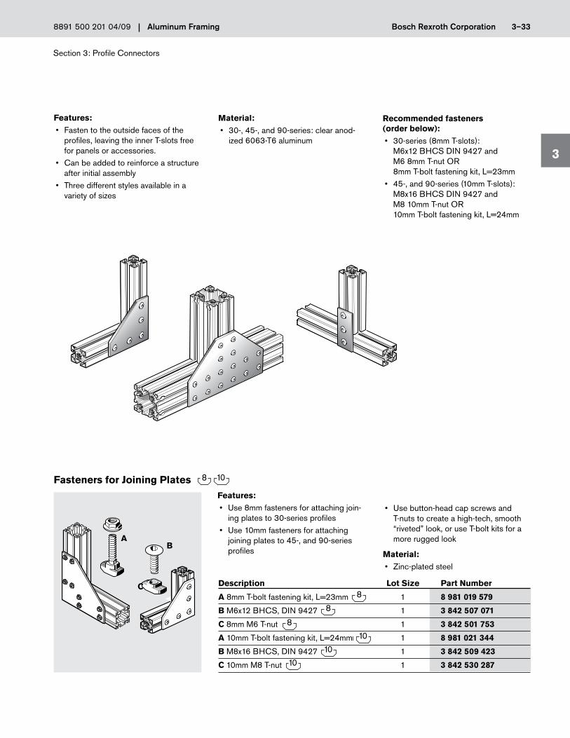
Features:• Fasten to the outside faces of the
profiles, leaving the inner T-slots free for panels or accessories.
• Can be added to reinforce a structure after initial assembly
• Three different styles available in a variety of sizes
Recommended fasteners (order below):• 30-series (8mm T-slots):
M6x12 BHCS DIN 9427 and M6 8mm T-nut OR 8mm T-bolt fastening kit, L=23mm
• 45-, and 90-series (10mm T-slots): M8x16 BHCS DIN 9427 and M8 10mm T-nut OR 10mm T-bolt fastening kit, L=24mm
Fasteners for Joining Plates
Description Lot Size Part Number
A 8mm T-bolt fastening kit, L=23mm 1 8 981 019 579
B M6x12 BHCS, DIN 9427 1 3 842 507 071
C 8mm M6 T-nut 1 3 842 501 753
A 10mm T-bolt fastening kit, L=24mm 1 8 981 021 344
B M8x16 BHCS, DIN 9427 1 3 842 509 423
C 10mm M8 T-nut 1 3 842 530 287
Features:• Use 8mm fasteners for attaching join-
ing plates to 30-series profiles• Use 10mm fasteners for attaching
joining plates to 45-, and 90-series profiles
• Use button-head cap screws and T-nuts to create a high-tech, smooth “riveted” look, or use T-bolt kits for a more rugged look
Material:• Zinc-plated steel
Material:• 30-, 45-, and 90-series: clear anod-
ized 6063-T6 aluminum
AB
C

Section 4: Fasteners
4
Bosch Rexroth CorporationAluminum Framing 4–18891 500 201 04/09
Features:• Installsanywherealongtheprofile’s
T-slot and rotates into position• Ridges“bite”intoprofiletolockthe
T-nut into position, and provide ESD protectionandresistancetovibration
• Largecontactsurfaceimprovesgrip-ping strength
• Taperednecksimplifiesassembly; T-nut is self-aligning in T-slot
• M4&M5threadshave2ridges• M6&M8threadshave4ridges• 8-32&10-32have2ridges• 1/4”&5/16”have4ridges
Material:• Zinc-plated8.8steel(exceptas notedbelow)
Tightening Lot Description Torque (± 5%) Size Part Number
6mm T-Nut M4 2.5 Nm 1 3 842 523 135
8mm T-Nuts M4 2.5 Nm 1 3 842 501 751
M5 5 Nm 1 3 842 501 752
M6 10 Nm 1 3 842 501 753
M6, nickel-plated 10 Nm 1 8 981 020 861
1/4”x20U.N.C. 10Nm 1 8 981 016 124
8-32U.N.C. 10Nm 1 8 981 016 122
10-32U.N.F. 10Nm 1 8 981 016 123
10mm T-Nuts M4 2.5 Nm 1 3 842 530 281
M5 5 Nm 1 3 842 530 283
M6 10 Nm 1 3 842 530 285
M8 25 Nm 1 3 842 530 287
M8, nickel-plated 25 Nm 1 8 981 019 580
1/4”x20U.N.C. 10Nm 1 8 981 021 323
8-32U.N.C. 10Nm 1 8 981 021 321
10-32U.N.F. 10Nm 1 8 981 021 322
5/16”x18U.N.C. 25Nm 1 8 981 021 324
T-Nuts
Fasteners
Die-cast nut gives maximum material thickness for more thread engagement.
Tapered design is self-aligning and locks in T-slot.
Ridges bite through the anodized surface for the best possible ESD connection and vibration resistance.
Helpful Hint
7.9
M4.5
16.5
5.9
M3
11.6
6mm T-Nut
8mm T-Nut
10mm T-Nut
9.8
M5.8
19.5
GoToboschrexroth-us.com/framingtogettheseinstockitemsFASTfromyourlocaldistributor

Section 4: Fasteners
4
Bosch Rexroth Corporation Aluminum Framing 4–2 8891 500 201 04/09
Features:• Insulatedcoverclipsontoan
8mm T-Nut to create an insulated 10mm T-Nut
• Usedtoisolategroundedelectricaldevices, such as light fixtures or outlet strips, from sensitive ESD components on aluminum profile structures
• Easysnap-onassembly• Allowsuseof8mmT-nutsin
10mm T-slots
Isolation Cap for 8mm T-Nut
Description Lot Size* Part Number
Isolation cap for 8mm T-nut 10 3 842 524 012
10
19.6
5.810
.8
Material:• Blackpolyamide6
4-2
* For smaller quantities, please contact your local distributor.
Material:• StainlessSteel316
Tightening Lot Description Torque (± 5%) Size* Part Number
6mm T-Nut M4 2.5 Nm 100 3 842 536 599
8mm T-Nuts M4 2.5 Nm 100 3 842 536 600
M5 5 Nm 100 3 842 536 601
M6 10 Nm 100 3 842 536 602
10mm T-Nuts M4 2.5 Nm 100 3 842 536 606
M5 5 Nm 100 3 842 536 605
M6 10 Nm 100 3 842 536 604
M8 25 Nm 100 3 842 536 603
Stainless Steel T-Nuts
Fasteners
5.9
1
4
11.6
M4
1.5
6
7.9
M
16.5
5.7
9.8
M
19.4
8.7
* For smaller quantities, please contact your local distributor.

Section 4: Fasteners
4
Bosch Rexroth CorporationAluminum Framing 4–58891 500 201 04/09
Features:• SlideintoendsofT-slot• Usedtofastenheavyloadsto T-slottedprofiles;seven-threaden-gagement for strong, secure mounting
• Largecontactsurfacewithinside ofprofile’sT-slotprovidessecurefastening
• CanbeeasilyrepositionedinT-slot• Springcanbeusedonany6mm,8mm,orheavy(H-series)10mmT-slottoholdT-blockinplacewhilemakingvertical connections
Material:• 6mm:stainlesssteel 8mm and 10mm: zinc-plated steel• Spring:springsteel
T-Blocks and Springs
7.5
17
8
8.5
21
8
16
16
6
20
20
10.5
8mm T-Block 8mm Spring
6.5
14
5.8
11.6
12
4
6mm T-Block 6mm Spring
10mm T-Block 10mm Spring
To simplify installation, use a springto hold the T-block in position in theT-slot while making vertical connections.
Helpful Hint
Tightening Lot Description Torque (± 5%) Size Part Number
6mm T-Blocks M4 2.5 Nm 1 3 842 523 140
M5 5 Nm 1 3 842 523 142
Springfor6mmT-block 1 3 842 523 145
8mm T-Blocks M4 2.5 Nm 1 3 842 514 928
M5 5 Nm 1 3 842 514 929
M6 10 Nm 1 3 842 514 930
M8 25 Nm 1 3 842 514 931
Springfor8mmT-block 1 3 842 516 685
10mm T-Blocks M5 5 Nm 1 3 842 528 741
M6 10 Nm 1 3 842 528 738
M8 25 Nm 1 3 842 528 735
Springfor10mmT-block 1 3 842 516 669
GoToboschrexroth-us.com/framingtogettheseinstockitemsFASTfromyourlocaldistributor
* For smaller quantities, please contact your local distributor.

Section 4: Fasteners
4
Bosch Rexroth Corporation Aluminum Framing 4–6 8891 500 201 04/09
Tightening Lot Description Torque (± 5%) Size* Part Number
A 6mm Swivel-In T-Blocks M4 2.5 Nm 1 3 842 536 669
2 x M4, stainless steel 2.5 Nm 100 3 842 536 673
B 8mm Swivel-In T-Blocks M5 5 Nm 1 3 842 529 319
M6 10 Nm 1 3 842 529 320
M8 25 Nm 1 3 842 529 321
M8, stainless steel 25 Nm 1 3 842 530 321
M5 with spring 5 Nm 1 3 842 529 295
M6 with spring 10 Nm 1 3 842 529 296
M8 with spring 25 Nm 1 3 842 529 297
2 x M5 5 Nm 100 3 842 536 675
C 10mm Swivel-In T-Blocks M6 10 Nm 1 3 842 529 323
M8 25 Nm 1 3 842 529 324
M8, stainless steel 25 Nm 1 3 842 530 316
M5 with spring 5 Nm 1 3 842 529 298
M6 with spring 10 Nm 1 3 842 529 299
M8 with spring 25 Nm 1 3 842 529 300
2 x M5 5 Nm 100 3 842 536 676
Features:• Canbeinsertedanywherealong theprofile’sT-slot,evenafterthestruc-turehasbeenbuilt
• UsedtofastenheavyloadstoT-slotted profiles;seven-threadengagementforstrong, secure mounting
• Largecontactsurfacewithinside ofprofile’sT-slotprovidessecurefastening
• CanbeeasilyrepositionedinT-slot• Theswivel-inspringT-blockissimilartostandardswivel-inT-blocks,butadds an integrated spring to hold the T-blockinplacewhilemakingverticalconnections
Material:• T-block:Zinc-platedgrade8steel(exceptasnotedbelow)
• Spring:springsteel
Swivel-In T-Blocks
Fasteners
6
GoToboschrexroth-us.com/framingtogettheseinstockitemsFASTfromyourlocaldistributor
* For smaller quantities, please contact your local distributor.
12
16
5
15
20
6
12
16
4.87.8
15
24
5.310.2
10mm Swivel-InT-Block
10mm Swivel-InSpring T-Block
8mm Swivel-InT-Block
8mm Swivel-InSpring T-Block
6mm Swivel-InT-Block
6mm 2-hole Swivel-In T-Blocks
12
6
9
15
3
9
12
3
8mm 2-hole Swivel-In T-Blocks
15
5.310mm 2-hole Swivel-In T-Blocks
3014
2412
8
A
B
C

Section 5: Doors and Door Components
5
Bosch Rexroth Corporation Aluminum Framing 5–6 8891 500 201 04/09
Features:• Hasopen10mmchannelalongonesidetoholdsliderbearingcarriages
• Usedtocreateoverheadslidingdoors• Optionalendstops(listedbelow)attachtoprofileendswithscrewsforsecurehold
• Optionalball-bearingcarriagesavail-able(listedbelow)
Material:• Rollerchannelprofile:anodizedalumi-
num• Endstop:blackpolyamide6
Roller Channel Profile C30x45
Description Lot Size Part Number
ProfileC30x45rollerchannel,pkg.20,5600mmlong 3 842 523 598
ProfileC30x45rollerchannel,single,5600mmlong 3 842 523 599
Ball-bearingcarriage 1 3 842 524 153
Endstop 1 3 842 521 513
Machined Options End Finish Part Number
ProfileC30x45rollerchannel,–/–,specifylength>100mm<5600mm 3 842 992 946/__mm
Contact your distributor for other machining options.
Ball-BearingCarriage
EndStop
30
10
45
24
12.5
66
50
38
4
21
45
30
Roller Channel Profile C30x45
Ball-Bearing Carriage
End Stop
FMAX=1500 N (337lbs.in)
Section 6: EcoSafe™ Guarding and Machine/Safety Enclosures
6
Bosch Rexroth Corporation Aluminum Framing 6–4 8891 500 201 04/09
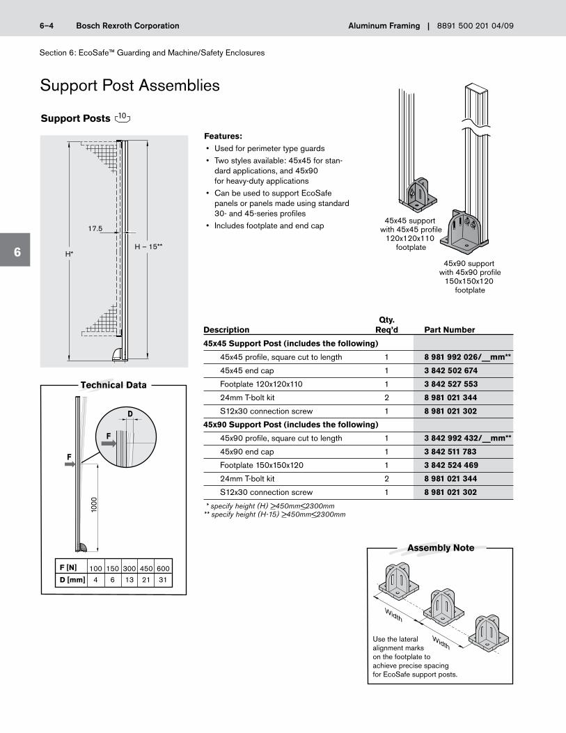
Support Post Assemblies
Features:• Usedforperimetertypeguards• Twostylesavailable:45x45forstan-dardapplications,and45x90 forheavy-dutyapplications
• CanbeusedtosupportEcoSafepanels or panels made using standard 30- and 45-series profiles
• Includesfootplateandendcap
Qty. Description Req’d Part Number
45x45 Support Post (includes the following)
45x45profile,squarecuttolength 1 8 981 992 026/__mm**
45x45endcap 1 3 842 502 674
Footplate120x120x110 1 3 842 527 553
24mmT-boltkit 2 8 981 021 344
S12x30connectionscrew 1 8 981 021 302
45x90 Support Post (includes the following)
45x90profile,squarecuttolength 1 3 842 992 432/__mm**
45x90endcap 1 3 842 511 783
Footplate150x150x120 1 3 842 524 469
24mmT-boltkit 2 8 981 021 344
S12x30connectionscrew 1 8 981 021 302
* specify height (H) >450mm<2300mm ** specify height (H-15) >450mm<2300mm
Support Posts
45x45 support with 45x45 profile
120x120x110 footplate
45x90 support with 45x90 profile
150x150x120 footplate
1000
F [N]
D [mm]
D
F
F
Technical Data
100
4
150
6
300
13
450
21
600
31
H*H – 15**
17.5
Use the lateral alignment marks on the footplate to achieve precise spacing for EcoSafe support posts.
Assembly Note
10

Section 6: EcoSafe™ Guarding and Machine/Safety Enclosures
6
Bosch Rexroth Corporation Aluminum Framing 6–18 8891 500 201 04/09
Frame Profile (22.5x30F)Features:• Steppedslottoholdpanels1.5mm,3mm,or5mmthick
• Economicalmeansforbuildingmate-rialtraysandshelves
• Endcapsandjoiningconnectorsavailableseparately
• Hasone8mmT-slot
Material:• Frameprofile:anodizedaluminum• Endcap:blackpolyamide12 (conductive)
• Joiningconnector:blackpolyamide
Non-Machined End Finish Options Lot Size* Part Number
Profile22.5x30F,pkg.of20,5600mmlong 3 842 515 229
Profile22.5x30F,single,5600mmlong 3 842 515 228
Cornerconnectorwithhardware 4 3 842 535 661
End cap 1 3 842 516 720
Machined Options End Finish Part Number
Profile22.5x30F,–/–,specifylength>30mm<5600mm 3 842 992 493/__mm
Please contact your distributor for other machining options.
OtherGuardingComponents
* For smaller quantities, please contact your local distributor.
S8 x 25
M8 x 16
30
6.5
6030
30
322.5
6.511.413.4
22.5
1.53530
8

Section 6: EcoSafe™ Guarding and Machine/Safety Enclosures
6
Bosch Rexroth CorporationAluminum Framing 6–238891 500 201 04/09
Heavy-Duty 8mm and 10mm Clamp Profiles
Features:• Alloweasyinstallationofpanels,
grilles and panes to standard profile frames
• Useforsurfacemountingthinpanelstoprofileswith8or10mmT-slots
• Lockingscrewsprovidestrong, secure connection
Material:• Anodizedaluminum
Machining Required:• Through-holesinframeprofileforlockingscrews(seeAssemblyNotebelow)
Description Part Number
8mmClampProfile1S,single,3000mmlong 3 842 524 057
8mmClampProfile1S,Pkg.10,3000mmlong 3 842 524 058
8mmClampProfile1S,Single,–/–,Specifylength>30mm<3000mm 3 842 993 017/__mm
8mmClampProfile2S,single,3000mmlong 3 842 524 060
8mmClampProfile2S,Pkg.10,3000mmlong 3 842 524 061
8mmClampProfile2S,Single,–/–,Specifylength>30mm<3000mm 3 842 993 018/__mm
10mmClampProfile1S,single,3000mmlong 3 842 524 063
10mmClampProfile1S,Pkg.10,3000mmlong 3 842 524 064
10mmClampProfile1S,Single,–/–,Specifylength>30mm<3000mm 3 842 993 019/__mm
10mmClampProfile2S,single,3000mmlong 3 842 524 066
10mmClampProfile2S,Pkg.10,3000mmlong 3 842 524 067
10mmClampProfile2S,Single,–/–,Specifylength>30mm<3000mm 3 842 993 020/__mm
27.5
16
13.5
19
10.5
12.5
DIN 912–M6x30
1 - 8
DIN 912–M4x20
1.5 - 5
45
16
13.5
30
10.5
12.5
Assembly Note
a = L - (n x W)2
NOTE: n = The number of screw holesW = Space between holes a = Dimension from hole to end profile must be ≥ 50mm L = Length of profileL
a
W
a
For optimum hole spacing in the frame profile, use the formula above to calculate (a) – the distance between the profile edge and the end holes
8mm Clamp Profiles
10mm Clamp Profiles 1S 2S
1S 2S
1mmto
8mm
45x45 and 10mm Clamp Profile 2S shown

Section 7: Floor to Frame Elements
Aluminum FramingLinear Motion and Assembly Technologies 8981 500 201 11/08Bosch Rexroth Corp.
7
Features:• Suitablefortoolcartsandsmallma-chinesthatmustbetransportedfromone area to another
• Availableinlockingornon-lockingver-sions
• Fourtypesareavailable:1 ConductiveforESDapplications2 Chemical-resistant,reinforcedwheels(resistanttopetroleumandalcoholbasedsolvents)
3 Floor-protectivetopreventmarringoffloorsurfaces
4 Solidcoreabrasion-resistant,whicharesuitableforESDandcleanroomapplications
• Types1, 3 and 4areavailablewith80mmor125mmdiameterwheels
• Type2isavailablewith125mmdiam-eterwheelsonly
Material:• Types1 and 4:solidrubberwiththreadpick-upprotection
• Type2:polyamidereinforced• Type3:solidrubberonpolyamiderim
Heavy-Duty Casters
Casters
57
108
/158
ISO 4762 M12x3035 Nm
Locking
110
40
108
/158
80/125
80/125
108
/158
80/125
Non-Locking
40
40
Trestle
Description Lot Size Part Number
1 Lockingheavy-dutycaster,80mm,conductive 1 3 842 521 682
1 Non-lockingheavy-dutycaster,80mm,conductive 1 3 842 521 680
1 Lockingheavy-dutycaster,125mm,conductive 1 3 842 531 783
1 Non-lockingheavy-dutycaster,125mm,conductive 1 3 842 531 784
2 Lockingheavy-dutycaster,125mm,chemical-resistant 1 3 842 515 367
2 Non-lockingheavy-dutycaster,125mm,chemical-resistant 1 3 842 515 366
3 Lockingheavy-dutycaster,80mm,floor-protective 1 3 842 521 686
3 Non-lockingheavy-dutycaster,80mm,floor-protective 1 3 842 521 684
3 Lockingheavy-dutycaster,125mm,floor-protective 1 3 842 515 369
3 Non-lockingheavy-dutycaster,125mm,floor-protective 1 3 842 515 368
4 Lockingheavy-dutycaster,125mm,solidcoreabrasionresistant 1 3 842 524 499
4 Non-lockingheavy-dutycaster,125mm,solidcoreabrasionresistant 1 3 842 524 500
4 Heavy-dutyTrestlecaster,80mm,solidcoreabrasionresistant 1 3 842 531 227
4 Heavy-dutyTrestlecaster,125mm,solidcoreabrasionresistant 1 3 842 531 229
CasterType 125mm wheel80mm wheel
Max. Load in N(lbs.)
1
2
3
4
600 (135)N/A
600 (135)600
1000 (225)1000 (225)800 (180)
1000 (225)
7-8

Section 7: Floor to Frame Elements
Aluminum FramingLinear Motion and Assembly Technologies 8981 500 201 11/08Bosch Rexroth Corp.
7
Features:• Usedtofastenstructuralprofilestofloors,decks,orshippingskids
• Doesnotinterferewithlevelingfeet• Availablein160mmor210mmlengths• Availablewithmountinghardware(two14mmT-boltfasteningkits),orasfoundationbracketonly
• Anchorboltmustbeordered separately
Material:• Zinc-platedsheetsteel
Foundation Brackets
Description Lot Size Part Number
160mmfoundationbracket 1 3 842 338 979 andmountinghardware
210mmfoundationbracket 1 8 981 003 224 andmountinghardware
160mmfoundationbracketonly 1 3 842 146 815
210mmfoundationbracketonly 1 3 842 146 848
8mm anchor bolt, L=76mm 1 3 842 526 560
7-14
90
90
40
40
8.5
8.0
Order Ø8mm Anchor Bolt Separately
Order Ø8mm Anchor Bolt Separately
22.5
22.5
4
4
42
42
160
210
100
5040
6040
55
409
9
GoToboschrexroth-us.com/framingtogettheseinstockitemsFASTfromyourlocaldistributor
Bosch Rexroth Corp.Linear Motion and Assembly Technologies8981 500 201 11/08 Aluminum Framing
Section 10: EcoFlow™ Conveyor and Transport Components
10
10-7
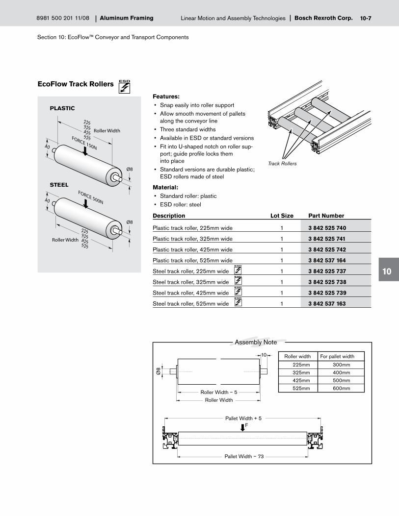
EcoFlow Track Rollers
Features:• Snapeasilyintorollersupport• Allowsmoothmovementofpallets
along the conveyor line• Threestandardwidths• AvailableinESDorstandardversions• FitintoU-shapednotchonrollersup-port;guideprofilelocksthem into place
• Standardversionsaredurableplastic;ESDrollersmadeofsteel
Material:• Standardroller:plastic• ESDroller:steel
Description Lot Size Part Number
Plastictrackroller,225mmwide 1 3 842 525 740
Plastictrackroller,325mmwide 1 3 842 525 741
Plastictrackroller,425mmwide 1 3 842 525 742
Plastictrackroller,525mmwide 1 3 842 537 164
Steeltrackroller,225mmwide 1 3 842 525 737
Steeltrackroller,325mmwide 1 3 842 525 738
Steeltrackroller,425mmwide 1 3 842 525 739
Steeltrackroller,525mmwide 1 3 842 537 163
Track Rollers
40
225325425
225325425
40
FORCE 150N
Ø8
Ø8
FORCE 500N
PLASTIC
STEEL
Roller Width
Roller Width525
525
Roller width
225mm
325mm
425mm
525mm
For pallet width
300mm
400mm
500mm
600mm
Assembly Note
F
Pallet Width − 73
Pallet Width + 5
Ø8
Roller WidthRoller Width − 5
10

Section 10: EcoFlow™ Conveyor and Transport Components
Aluminum FramingLinear Motion and Assembly Technologies 8981 500 201 11/08Bosch Rexroth Corp.
10
Features:• Constructarollercurvetoconnect
two straight sections• Allowssmoothpalletflowwhilemain-
taining leading edge orientation• Kitincludesinnerandouterpalletguides,20RollerBalls,aninstallationtemplate,andallnecessaryhardwareforinstallationonanEcoFlowCornerTabletop(soldseparately,seebelow)
• Canbeusedtoconstructrollercurvesforallthreestandardpalletsizes
• CornerTabletopsavailableineconomyandESDversions
• UseofEcoFlowpalletcornersisrec-ommended on all pallets
Material:• Rollerballs:stainlesssteelballwithgalvanizedsteelcase
• Guides:steel• Tabletops:hard-coatedchipboard
EcoFlow Roller Transfer Kit and EcoFlow Corner Tabletop
Description Lot Size Part Number
EcoFlowrollertransferkit 1 3 842 525 756
EcoFlowcornertabletop,economy 1 3 842 521 675
EcoFlowcornertabletop,ESD 1 3 842 537 247
10-12
555
28 (E
SD
)38
(STD
) 895
b + 5
485
Roller Transfer Kit
Corner Tabletop
EcoFlowManualConveyors
Features:• Constructcustomrollercurvesorrollertransfertables
• Ensuresmoothpalletmovement• ReplacewornordamagedrollersinEcoFlowRollerTransferKits
• Easyinstallation;forproperinstallationusea24mmForstnerbittoprepareahole in the tabletop
Material:• Stainlesssteelballwithgalvanized
steel case
EcoFlow Roller Ball
Description Lot Size Part Number
EcoFlow roller ball 1 3 842 541 008
3124
21
9.5
11.5
Ø15
.8
Fmax = 500N
Bosch Rexroth Corp.Linear Motion and Assembly Technologies8981 500 201 11/08 Aluminum Framing
Section 11: Ergonomic Workplace Equipment
11
11-29
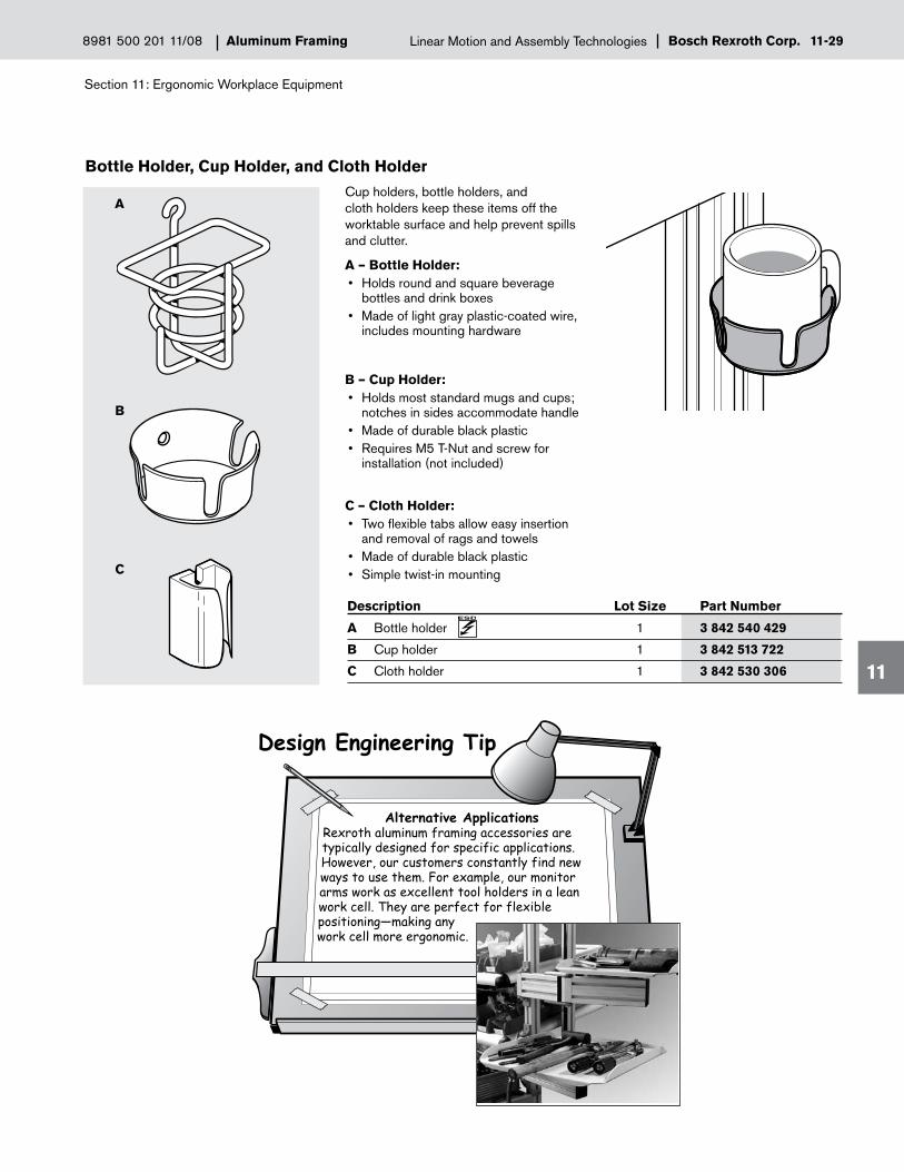
Bottle Holder, Cup Holder, and Cloth Holder
Cup holders, bottle holders, and cloth holders keep these items off the worktable surface and help prevent spills and clutter.
A – Bottle Holder:• Holdsroundandsquarebeverage
bottles and drink boxes • Madeoflightgrayplastic-coatedwire,
includes mounting hardware
B – Cup Holder:• Holdsmoststandardmugsandcups;
notches in sides accommodate handle • Madeofdurableblackplastic• RequiresM5T-Nutandscrewfor
installation (not included)
C – Cloth Holder:• Twoflexibletabsalloweasyinsertion
and removal of rags and towels • Madeofdurableblackplastic• Simpletwist-inmounting
Description Lot Size Part Number
A Bottle holder 1 3 842 540 429
B Cup holder 1 3 842 513 722
C Cloth holder 1 3 842 530 306
A
B
C
Alternative ApplicationsRexroth aluminum framing accessories are typically designed for specific applications. However, our customers constantly find new ways to use them. For example, our monitor arms work as excellent tool holders in a lean work cell. They are perfect for flexible positioning—making any work cell more ergonomic.
Design Engineering Tip

Section 11: Ergonomic Workplace Equipment
Aluminum FramingLinear Motion and Assembly Technologies 8981 500 201 11/08Bosch Rexroth Corp.
11
S8 x 25Self-tapping
Connection ScrewSection 3
30 x 30End CapSection 9
30x30
Center Profile
End Profile
Alignment Insert
5025
Ø7.8
Features:• CreatesasurfacewithmanyevenlyspacedT-slotstoeasilymountandre-locate assembly fixtures and prototype components
• Two100mmwideinterlockingprofilesallow you to create a fixture plate as large as needed by combining end and center profiles
• Alignmentinsertshelpmaintainproperalignment during assembly
• Endscanbetiedtogetherusing30x30profileandself-tappingscrews(sold separately)
• T-slotsuse8mmhardwarehowever,cover strip is not compatible with fixture plate
Machining required:• 7.8mmaccessholesin30x30profile,
spaced every 50mm, starting 25mm from one end
Fixture Plate Components
2525
100
7.3
8.7
12.5
2.7
25252525
30
CENTER PROFILE
2525
100
7.3
8.7
12.5
2.7
25252525
30 8
ENDPROFILE
Description Lot Size Part Number
30x100 end fixture plate profile, 3300mm long 1 3 842 519 447
30x100 center fixture plate profile, 3300mm long 1 3 842 519 448
Alignmentinsert,44mmlong 1 3 842 520 922
Endfixtureplate-/- 1 3 842 993 337
Centerfixtureplate-/- 1 3 842 993 336
11-38

Section 12: Accessories
Aluminum FramingLinear Motion and Assembly Technologies 8981 500 201 11/08Bosch Rexroth Corp.
12
Features:• Idealforattachingshelves,fixtures,etc.thatcanbepositionedatvariableangles and locked in place
• Allowsupto180°rangeofmotion• Canhandlemoments(FxL)upto
mmax=40Nm• SelectswivelbracketkitbyT-slotsizeofmovableprofileandfixedprofile
• Includebracket,lockinglever,allnecessarymountinghardware,andinstructionsheet
Material:• Swivelbracket:galvanizedsteel• Lockingleverhandle:blackpolyamide• Spindle:pressuredie-castzinc• Hardware:zinc-platedsteel• Threadedstem:galvanizedsteel
class 5.8
Swivel Bracket Kits
Description Lot Size Part Number
MovableSwivelbracketkitA 1 3 842 538 275
MovableSwivelbracketkitB 1 3 842 538 276
Accessories
30
100
130
R65
R50
22.56.
3
15
7.5
2.5
8.1
8.2
Fixed
Movable
12-4
P1 � P2
8 8
10 8
108 108
10 1010 10
1088 8
10 1010 8
8
+1x +2x
DIN 125A6.4
M6x12
M8x16M8x16ISO 4762
ISO 4762M6x16
+2x
DIN 125A6.4
ISO 4762
1010 10
8
+1x +2x
DIN 125A6.4
M6x12
M8x12M8x12ISO 4762
ISO 4762M6x16
+2x
DIN 125A6.4
ISO 4762
88 10
A
B

Bosch Rexroth Corp.Linear Motion and Assembly Technologies8981 500 201 11/08 Aluminum Framing
Section 15: Tools
15
Features:• Built-in lock/release knob
simplifies use• Forusewithprofileswith6mmT-slots,including20x20,20x40,etc.
• Twoversionsareavailable:• Positions5.8mmaccessholesforTorxheadconnectionscrewsand8mmholesfor20seriesquickconnectors.
6mm Drill and Boring Jig
Description Lot Size Part Number
Drillandboringjigfor5.8mmholes 1 3 842 537 556
15-3
6
Features:• Providesproperendspacingwhen
drilling 17mm holes in 10mm T-slotted profileswitha45°endmiter
• Typicallyusedwhenpreparing profilesforusewithend-to-endandend-to-sidevariableangleconnectors
• Built-inlock/releaselever simplifies use
10mm Miter Drilling Jig
Description Lot Size Part Number
10mm miter drilling jig 1 3 842 516 731
10
110
40
40
90°135°
Ø1718
Ø5.8
Ø5.8
1220
5.8 8
8
10
10
70
Ø8.0

Section 16: Engineering Data and Specifications
Aluminum FramingLinear Motion and Assembly Technologies 8981 500 201 11/08Bosch Rexroth Corp.
16
Technical Data for Profiles
16-0
Material designation according to DIN (ISO) for Bosch profiles AlMgSi 0.5 F25 AW-6063-T66
Material number according to DIN (ISO) 3.3206.7 AW-6063-T66
Tensile strength (expected) Rm = 250 N/mm2 (36,000 lb./in.2)
0.2% proof stress (expected) Rp0,2 = 200 N/mm2 (29,000 lb./in2)
Elongation at rupture A5 or A10 A5 = 10% A10 = 8%
Modulus of elasticity E E = 70,000 N/mm2 (10x106 lb./in2)
Brinell hardness 75 HB
Coefficient of linear expansion α(-50°...+20°C) = 21.8 x 10-61/K α(-58°...+68°F) = 12.1 x 10⁻⁶in/in/°F α(+20°...+100°C) = 23.4 x 10-61/K α(+68°...+212°F) = 13.0 x 10⁻⁶in/in/°F
Poisson’s ratio µ = 0.34
Anodizing process–layer thickness–layer hardness E6/EV1-12µm - 300HV R204-(.0003 in-300HV)
Metric U.S. Equivalent

Section 16: Engineering Data and Specifications
Aluminum FramingLinear Motion and Assembly Technologies 8981 500 201 11/08Bosch Rexroth Corp.
16
16-6
Ø11 (L = 30 mm)
Ø17 (L = 40 mm)
Ø17 (L = 45 mm)
Ø17 (L = 50 mm)
Ø17 (L = 60 mm)
Ø17 (L = 80 mm)
Ø17 (L = 90 mm)
Ø17 (L = 100 mm)
Ø11 (L = 11 mm)
2500 (562)
4000 (899)
4000 (899)
4000 (899)
4000 (899)
5000 (1124)
5000 (1124)
5000 (1124)
500 (112)
500 (112)
50 (443)
50 (443)
7 (62)
10 (89)
500 (112)
1000 (224)
50 (443)
2200 (495) 50 (443)
2800 (629)
600 (135)
2500 (562)
3000 (674)
3500 (786)
3500 (786)
3500 (786)
3500 (786)
500 (112)
800 (180)
1300 (292)
8 (71)
43 (381)
80 (708)
100 (886)
110 (975)
110 (975)
110 (975)
195 (1728)
-
60 (531)
180 (1593)
180 (1593)
200 (1770)
200 (1770)
800 (7080)
800 (7080)
1000 (8850)
20 (177)
40 (354)
60 (531)
65 (575)
80 (708)
170 (1505)
200 (1770)
480 (4248)
6 Nm (53 lb-in)
20 Nm (177 lb-in)
20 Nm (177 lb-in)
20 Nm (177 lb-in)
20 Nm (177 lb-in)
20 Nm (177 lb-in)
20 Nm (177 lb-in)
20 Nm (177 lb-in)
10
10
1010
10
10
10
8
10
10
8
8
6
Bolt Connector
Bolt Connector
Bolt Connector
Inside-to-Outside Gusset
Inside-to-Inside Gusset
ConnectionScrew
Ø17 (L = 15 mm)
7 Nm (62 lb-in)
12 Nm (106 lb-in)
10
10
Ø28 (L = 19.5 mm)
35 Nm (310 lb-in)S12 x 30 mm
3000 (674) 80 (708)1035 Nm (310 lb-in)
10
10
10
10
M12 x 30 mm
25 Nm (221 lb-in)
N (lbs)
10 10
10 10
12 Nm (106 lb-in)8 mm
15 Nm (133 lb-in)10 mm
8 8
6 mm 6 6
12 Nm (106 lb-in)
3 Nm (26 lb-in)
8 mm 8 8
15 Nm (133 lb-in)
15 Nm (133 lb-in)
15 Nm (133 lb-in)
15 Nm (133 lb-in)
15 Nm (133 lb-in)
10 mm
25 Nm (221 lb-in)
86 Nm (53 lb-in)
S8 x 25 mm
10 Nm (88 lb-in)S6 x 16 mm
10 (89)
30 (266)
30 (266)
30 (266)
60 (531)
15 (133)35 (311)
-
-
50 (443)
100 (886)
-
-
-
-
-
-
-
Load carrying capacities of profile connectors
( ±5%) Nm (lb-in) Nm (lb-in)
Fmax Mmax Mmax
500 (112) 40 (354)
2000 (450) 70 (619)
4000 (899) 140 (1239)
-
-
-
Quick
TensionConnector
Connector12 Nm (106 lb-in)
8 mm T-bolt
SV8–30 series profiles
SV10
SV10L–45 series profiles
40H series profiles
45H series profiles
60H series profiles
Ø11 Barrel
12 Nm (106 lb-in)10 mm T-boltØ11 Barrel
25 Nm (221 lb-in)10 mm T-boltØ17 Barrel
8 10
10 10
8 8

Bosch Rexroth Corp.Linear Motion and Assembly Technologies8981 500 201 11/08 Aluminum Framing
Section 16: Engineering Data and Specifications
16
Mmax Mmax
2
Mmax
2
(±5%)
10 Nm (88 lb-in)
Corner Cube 20/2S
10 Nm (88 lb-in)
Corner Cube 20/3S
25 Nm (221 lb-in)
Corner Cube 30/2S
25 Nm (221 lb-in)
Corner Cube 30/3S
35 Nm (310 lb-in)
Corner Cube 45/2S
35 Nm (310 lb-in)
35 Nm (310 lb-in)
35 Nm (310 lb-in)
Corner Cube 45/3S
8
8
6
6
10
10
10
10
18 (159)
80 (709)
85 (753)
150 (1329)
200 (1772)
170 (1506)
240 (2126)
23 (204)
Nm (lb-in) Nm (lb-in)
45 x 45
45 x 45H
45 x 45
45 x 45H
6 mm
6 mm
8 mm
8 mm
10 mm
10 mm
Load carrying capacities of profile connectors
-
-
-
-
Corner Cube 40/2S
Corner Cube 40/3S
60 (532)
70 (620)
10 mm
10 mm
-
-
35 Nm (310 lb-in)
35 Nm (310 lb-in)
10
10
Corner Cube 50/2S
Corner Cube 50/3S
120 (1063)
140 (1240)
10 mm
10 mm
-
-
-
-
-
-
* Load Ratings when Radius Compensator is used with indicated connector
* * *
600 (135)
600 (135)
1035 Nm (310 lb-in)
1030 Nm (310 lb-in)
825 Nm (221 lb-in)
These values were determined under static conditions and are guide values only. Allow appropriate safety margins during planning!
S8
Quick Connector
Quick Connector
Quick Connector
M12, S12
M12, S12
1000 (224)
1000 (224)
1200 (270)
1200 (270)
37 (327)
37 (327)
47 (416)
47 (416)
53 (469)
53 (469)
28 (248)
28 (248)
55 (487)
55 (487)
59 (522)
59 (522)
30x30
40x40
45x45
Radius Compensator
25 Nm (221 lb-in) 10 10
22 Nm (221 lb-in) 10 10
12 Nm (106 lb-in) 8 8
16-7

Section 16: Engineering Data and Specifications
Aluminum FramingLinear Motion and Assembly Technologies 8981 500 201 11/08Bosch Rexroth Corp.
16
L
FF F
f
f
f
1 2 3
Profile bending deflection for static load case from force F.
Profile bending deflection from the profile’s own weight
Determination of maximum occurring bending stress
E = modulus of elasticity = 70,000 N/mm2
(Young’s modulus = 10x106 lb/in2)
f = F x L3
3E x I x 104mm
f = FL3
3E I in
f = F x L3
48E x I x 104mm
f = FL3
48E I in
f = F x L3
192E x I x 104mm
f = FL3
192E I in
f = F x L3
8E x I x 104mm
f = FL3
8E I in
f = 5 x F x L3
384E x I x 104mm
f = 5FL3
384E I in
f = F x L3
384E x I x 104mm
f = FL3
384E I in
mm in
mm in
mm in
σmax < 200 N/mm2
Force = F [N](lb)Amount of Deflection = f [mm](in)
Length of Profile = L [mm](in)Inertia = I [cm4](in4)
Section Modulus = W [cm3](in3)
Metric
σmax = maximum allowable bending stress = 28,000 lb/in2
Bending Deflection for Aluminum Profiles
16-8
U.S. Equivalent
σ = F x L
W X 103
σ = FL
W
σ = F x L
4W X 103
σ = FL
4W
σ = F x L
8W X 103
σ = FL
8W