ddc and edid - technical authors | technical writers | technical
TRANSCRIPT
�
WHITE PAPER February 2009
DDC and EDIDHow video displays learned to talk back
Although far from being actual living organisms, personal computers have a his-tory with revealing similarities to the fight for survival pursued by all animal spe-cies. Indeed, the rather short but frenetic development period from the late 1970s to the present day exhibits many of the Darwinian traits found within any natural habitat over time: Increasing overall sophistication, long-lived successful dynasties and short-lived evolutionary dead-ends.
Like internal organs of the body, every computer is built from myriad sub-compo-nents, each of which (as a species) is continually undergoing its own progression. One section that has shown increasingly rapid rates of development within the last two decades is the most visible of all: The video graphics system.
Video systems – the early daysThings began relatively simply in the early 1980s with just two options: a simple text-only monochrome video system, called MDA (Monochrome Display Adapter) or a rudimentary colour system, called CGA (Color Graphics Adapter). In those early days IBM determined most of the development directions in the PC world; Apple were on a completely different path with their Apple II and Macintosh systems.
In 1984, IBM introduced a new video system to coincide with the release of the IBM PC/AT computer, creating yet another acronym: EGA (Enhanced Graphics Adapter). The new video system provided improved colour graphic capabilities and could also support the displays designed for the previous two systems. This presented a problem because although MDA, CGA and EGA displays all used the same type of connector, the video signals sent through them were different. Permanent damage could be caused to a monochrome display if connected to a controller that was sending out colour CGA or EGA signals. As there was no way for an EGA controller to determine which type of display was connected, the mode had to be set manually using miniature switches at the rear of the compu-ter. This was prone to error and caused a good many technical support calls. A method was clearly required for the attached display to declare its capabilities to the video controller within the computer.
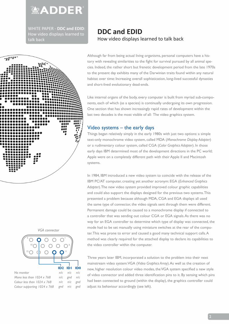
Three years later IBM, incorporated a solution to the problem into their next mainstream video system: VGA (Video Graphics Array). As well as the creation of new, higher resolution colour video modes, the VGA system specified a new style of video connector and added three identification pins to it. By sensing which pins had been connected to ground (within the display), the graphics controller could adjust its behaviour accordingly (see left).
�
WHITE PAPER - DDC and EDID: How video displays learned to talk back
DDC and EDIDHow video displays learned to talk back
ID2n/cn/cn/cgnd
ID1n/cgndn/cn/c
ID0n/cn/cgndgnd
No monitorMono less than 1024 x 768Colour less than 1024 x 768Colour supporting 1024 x 768
1
6
11
5
10
15
VGA connector
This was a significant improvement and meant an end to the cumbersome and mistake-inducing configuration switches. However, as a means of communication between display and computer, it was rudimentary and limiting.
By the end of the decade a significant split was occurring. IBM had been attempt-ing to regain control of the market with its PS/2 range and a new high-end video standard, called XGA (eXtended Graphics Array). The rest of the PC industry had other ideas and, thanks to the newly formed VESA group (Video Electronics Stand-ards Association), a rival video design was available, called Super VGA.
Super VGA: IBM loses controlSuper VGA (or SVGA) was the first major PC video system released to an open
standard; published and available to all, rather than being developed by one com-pany and then reverse-engineered by their competitors. Actually ‘standard’ is too strong a word for Super VGA. It was more of an umbrella term under which nu-merous developments could be made through a combination of common consent and/or commercial evolution. This was the point at which IBM lost its dominant role over the direction of new video standards; from now on development would be more akin to a democracy.
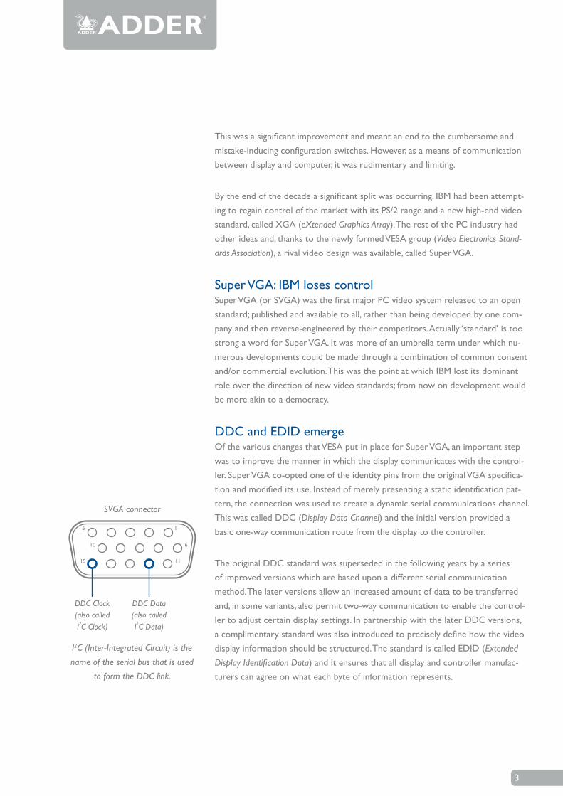
DDC and EDID emergeOf the various changes that VESA put in place for Super VGA, an important step was to improve the manner in which the display communicates with the control-ler. Super VGA co-opted one of the identity pins from the original VGA specifica-tion and modified its use. Instead of merely presenting a static identification pat-tern, the connection was used to create a dynamic serial communications channel. This was called DDC (Display Data Channel) and the initial version provided a basic one-way communication route from the display to the controller.
The original DDC standard was superseded in the following years by a series of improved versions which are based upon a different serial communication method. The later versions allow an increased amount of data to be transferred and, in some variants, also permit two-way communication to enable the control-ler to adjust certain display settings. In partnership with the later DDC versions, a complimentary standard was also introduced to precisely define how the video display information should be structured. The standard is called EDID (Extended Display Identification Data) and it ensures that all display and controller manufac-turers can agree on what each byte of information represents.
�
DDC Clock(also calledI C Clock)2
DDC Data(also calledI C Data)2
1
6
11
5
10
15
I2C (Inter-Integrated Circuit) is the name of the serial bus that is used
to form the DDC link.
SVGA connector
In combination, DDC (the link) and EDID (the content) have been highly success-ful in promoting essential dialogue between controllers and displays. Using this system, each display device and controller can automatically arbitrate and agree upon the most effective configuration to use.
In recent times DDC and EDID have been adopted by the high resolution DVI (Digital Visual Interface) standard. They have also become an integral part of general system setup procedures (for DVI and SVGA systems) for two main reasons:
Firstly, with the advent of large LCD panels, new widescreen resolutions are becoming more prevalent and these require video controllers to significantly alter their output signals. To cater for larger and more complex displays, the later EDID versions provide greater memory space to allow more information to be declared to the video controller.
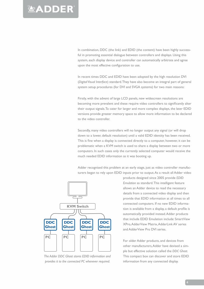
Secondly, many video controllers will no longer output any signal (or will drop down to a lower, default resolution) until a valid EDID identity has been received. This is fine when a display is connected directly to a computer, however, it can be problematic when a KVM switch is used to share a display between two or more computers. In such cases only the currently selected computer would receive the much needed EDID information as it was booting up.
Adder recognised this problem at an early stage, just as video controller manufac-turers began to rely upon EDID inputs prior to output. As a result all Adder video
products designed since 2005 provide EDID Emulation as standard. This intelligent feature allows an Adder device to read the necessary details from a connected video display and then provide that EDID information at all times to all connected computers. If no new EDID informa-tion is available from a display, a default profile is automatically provided instead. Adder products that include EDID Emulation include: SmartView XPro, AdderView Matrix, AdderLink AV series and AdderView Pro DVI series.
For older Adder products, and devices from other manufacturers, Adder have devised a sim-ple but effective solution called the DDC Ghost. This compact box can discover and store EDID information from any connected display.
4
DDCGhost
DDCGhost
DDCGhost
DDCGhost
PC PC PC PC
KVM Switch
The Adder DDC Ghost stores EDID information and provides it to the connected PC whenever required.
The DDC Ghost can then be fitted in-line to a computer’s SVGA video output in order to permanently provide the required information. The DDC Ghost fully supports EDID 2.0, so it is ideal for use with host products that support only the earlier EDID standard and need to be used with widescreen panels.
Beginning with the new AdderView 4 Pro DVI switch, Adder are offering an even more sophisticated feature called Hybrid DDC. This provides continual display information to all computers, as with the existing EDID Emulation scheme. How-ever, Hybrid DDC goes one step further by allowing full two-way communication between the display and the currently selected computer. This allows the compu-ter to make adjustments to the display (e.g. brightness, colour balance, etc.), an important requirement for applications such as medical imaging. Hybrid DDC can also transfer the authorisation signals that are required by HDCP (High-bandwidth Digital Content Protection) compliant video sources and displays that ensure high definition copy protection.
Future generations?This paper has touched upon just a handful of pivotal video graphic systems; there are many more successes and failures that litter the historical records as well as landfill sites worldwide. The evolutionary race to develop ever better, faster, cheaper and smarter graphics systems continues at full pace. Work is currently progressing upon the next mass-market replacement for the DVI and HDMI (High-Definition Multimedia Interface) standards. The front runner for this title appears to be the DisplayPort standard, devised by VESA, which is supported by nu-merous manufacturers. Time, and the market, will tell whether DisplayPort or an alternative scheme achieves the expected levels of success. One thing’s for sure, when the market demands a way to share, extend or secure the next generation of video systems, Adder will create the solution.
5
About Adder
Adder is a leading developer and manufacturer of KVM switches, video and audio extenders, KVM-over-IP devices, and remote management solutions. By empowering IT professionals to securely manage technology resources anywhere in the world, Adder solutions help customers make the best use of those resources while driving down total cost of ownership. In addition, through its advanced video and audio extension solutions, Adder is enabling the next generation of digital signage.
More information about Adder and its solutions is available at www.adder.com.
ADDER TECHNOLOGYTechnology House, Trafalgar Way, Bar Hill,Cambridge, CB23 8SQ UKTel: +44 (0)1954 780044 Fax: +44 (0)1954 780081email: [email protected] www.adder.com
ADDER CORPORATION29 Water StreetNewburyport, MA 01950 USATel: +1 888 932 3337 Fax: +1 888 275 1117email: [email protected] www.adder.com
ADDER TECHNOLOGY ASIA PACIFIC6 New Industrial Road#07-01 Hoe Huat Industrial Building, Singapore 536199Tel: +65 6288 5767 Fax: +65 6284 1150email: [email protected] www.adder.com
Europe
ADDER TECHNOLOGY,
Technology House, Trafalgar Way, Bar Hill, Cambridge, CB23 8SQ, UK
Telephone: +44 (0)1954 780044 Fax: +44 (0)1954 780081,
Email: [email protected]
ADDER BERLIN, Central & Eastern Europe,
Hohenstaufenstr. 37, 10779 Berlin
Telephone: +49 (0)30 8849 67-50, Fax: +49 (0)30 8849 67-48
Email: [email protected]
ADDER AMSTERDAM, BENELUX, FR, ES, IT, PT, GR, TK,
Schinkeldijkje 2a III, 1432 CE Aalsmeer, The Netherlands
Telephone: +31206400120
Email: [email protected]
USA
ADDER CORPORATION,
29 Water Street, Newburyport, MA 01950 USA
Telephone: 888-932-3337, Fax: 888-275-1117
Email us: [email protected]
Asia
ADDER TECHNOLOGY ASIA PACIFIC,
6 New Industrial Road, Hoe Huat Industrial Building #07-01,, Singapore 536199
Telephone: +65 6288 5767, Fax: +65 6284 1150
Email: [email protected]