ddcs expert user's manual v1 (part1) - nvcnc.net
TRANSCRIPT

Shenzhen Digital Dream Numerical Technology Co., Ltd.
DDCS-E x p e r tStandalone Motion Controller
Users Manual V1
Digital Dream Standalone Motion Controller DDCS-Expert Users ManualPage-1
● ● ● ● ● ● ● ● ● ● ● ● ● ● ● ● ● ● ● ● ● ● ● ● ● ● ● ● ● ● ● ● ● ● ● ● ● ● ● ● ● ● ● ● ● ● ● ●
● ● ● ● ● ● ● ● ● ● ● ● ● ● ● ● ● ● ● ● ● ● ● ● ● ● ● ● ● ● ● ● ● ● ● ● ● ● ● ● ● ● ● ●
● ● ● ● ● ● ● ● ● ● ● ● ● ● ● ● ● ● ● ● ● ● ● ● ● ● ● ● ● ● ● ● ● ● ● ● ● ● ● ● ● ● ● ● ● ● ● ● ● ● ● ● ●
● ● ● ● ● ● ● ● ● ● ● ● ● ● ● ● ● ● ● ● ● ● ● ● ● ● ● ● ● ● ● ● ● ● ● ● ● ● ● ● ● ● ● ● ● ● ● ● ● ●
● ● ● ● ● ● ● ● ● ● ● ● ● ● ● ● ● ● ● ● ● ● ● ● ● ● ● ● ● ● ● ● ● ● ● ● ● ● ● ● ● ● ● ● ● ● ●
● ● ● ● ● ● ● ● ● ● ● ● ● ● ● ● ● ● ● ● ● ● ● ● ● ● ● ● ● ● ● ● ● ● ● ● ●
● ● ● ● ● ● ● ● ● ● ● ● ● ● ● ● ● ● ● ● ● ● ● ● ● ● ● ● ● ● ● ● ● ● ● ● ● ● ● ● ● ● ● ● ● ● ● ● ● ● ● ● ● ● ● ● ● ● ●
● ● ● ● ● ● ● ● ● ● ● ● ● ● ● ● ● ● ● ● ● ● ● ● ● ● ● ● ● ● ● ● ● ● ● ● ● ● ● ● ● ● ● ● ● ● ● ● ● ● ● ● ● ●
● ● ● ● ● ● ● ● ● ● ● ● ● ● ● ● ● ● ● ● ● ● ● ● ● ● ● ● ● ● ● ● ● ● ● ● ● ● ● ● ● ● ● ● ● ● ● ● ● ● ● ● ● ● ● ● ● ● ● ● ● ● ● ● ● ● ● ● ● ●
● ● ● ● ● ● ● ● ● ● ● ● ● ● ● ● ● ● ● ● ● ● ● ● ● ● ● ● ● ● ● ● ● ● ● ● ● ● ● ● ● ● ● ● ● ● ● ● ● ● ● ● ● ● ● ● ● ● ● ● ● ● ● ● ● ● ● ● ● ● ● ● ●
● ● ● ● ● ● ● ● ● ● ● ● ● ● ● ● ● ● ● ● ● ● ● ● ● ● ● ● ● ● ● ● ● ● ● ● ● ● ● ● ● ● ● ● ● ● ● ● ● ● ● ● ● ● ● ● ● ● ● ● ● ● ● ● ● ● ● ● ● ● ● ● ●
● ● ● ● ● ● ● ● ● ● ● ● ● ● ● ● ● ● ● ● ● ● ● ● ● ● ● ● ● ● ● ● ● ● ● ● ● ● ● ● ● ● ● ● ● ● ● ● ● ● ● ● ● ● ● ● ● ● ● ● ● ● ● ●
● ● ● ● ● ● ● ● ● ● ● ● ● ● ● ● ● ● ● ● ● ● ● ● ● ● ● ● ● ● ● ● ● ● ● ● ● ● ● ● ● ● ● ● ● ● ● ● ● ● ● ● ● ● ● ● ● ● ● ● ● ● ● ● ● ● ●
● ● ● ● ● ● ● ● ● ● ● ● ● ● ● ● ● ● ● ● ● ● ● ● ● ● ● ● ● ● ● ● ● ● ● ● ● ● ● ● ● ● ● ● ● ● ● ●
● ● ● ● ● ● ● ● ● ● ● ● ● ● ● ● ● ● ● ● ● ● ● ● ● ● ● ● ● ● ● ● ● ● ● ● ● ● ● ● ● ● ● ● ● ● ● ● ● ● ● ● ● ● ● ● ● ● ● ● ● ● ● ● ● ●
● ● ● ● ● ● ● ● ● ● ● ● ● ● ● ● ● ● ● ● ● ● ● ● ● ● ● ● ● ● ● ● ● ● ● ● ● ● ● ● ● ● ● ● ● ● ● ● ● ● ● ● ● ● ● ● ● ● ● ● ● ● ●
● ● ● ● ● ● ● ● ● ● ● ● ● ● ● ● ● ● ● ● ● ● ● ● ● ● ● ● ● ● ● ● ● ● ● ● ● ● ● ● ● ● ● ● ● ● ● ● ● ● ● ● ● ● ● ● ● ● ● ● ● ●
● ● ● ● ● ● ● ● ● ● ● ● ● ● ● ● ● ● ● ● ● ● ● ● ● ● ● ● ● ● ● ● ● ● ● ● ● ● ● ● ● ● ● ● ● ● ● ● ● ● ● ● ● ● ● ● ● ● ● ● ●
● ● ● ● ● ● ● ● ● ● ● ● ● ● ● ● ● ● ● ● ● ● ● ● ● ● ● ● ● ● ● ● ● ● ● ● ● ● ● ● ● ● ● ● ● ● ● ● ● ● ● ● ● ● ● ● ● ● ● ●
● ● ● ● ● ● ● ● ● ● ● ● ● ● ● ● ● ● ● ● ● ● ● ● ● ● ● ● ● ● ● ● ● ● ● ● ● ● ● ● ● ● ● ● ● ● ● ● ● ● ● ● ● ●
● ● ● ● ● ● ● ● ● ● ● ● ● ● ● ● ● ● ● ● ● ● ● ● ● ● ● ● ● ● ● ● ● ● ● ● ● ● ● ● ● ● ● ● ● ● ● ● ● ● ● ● ● ● ● ● ● ● ● ● ● ● ● ● ●
● ● ● ● ● ● ● ● ● ● ● ● ● ● ● ● ● ● ● ● ● ● ● ● ● ● ● ● ● ● ● ● ● ● ● ● ● ● ● ● ● ● ● ● ● ● ● ● ● ● ● ● ● ● ●
● ● ● ● ● ● ● ● ● ● ● ● ● ● ● ● ● ● ● ● ● ● ● ● ● ● ● ● ● ● ● ● ● ● ● ● ● ● ● ● ● ● ● ● ● ●
● ● ● ● ● ● ● ● ● ● ● ● ● ● ● ● ● ● ● ● ● ● ● ● ● ● ● ● ● ● ● ● ● ● ● ● ● ● ● ● ● ● ● ● ● ● ● ● ● ● ● ● ● ● ● ● ●
● ● ● ● ● ● ● ● ● ● ● ● ● ● ● ● ● ● ● ● ● ● ● ● ● ● ● ● ● ● ● ● ● ● ● ● ● ● ● ● ● ● ● ● ● ● ● ● ● ● ● ● ● ● ● ● ● ● ● ● ● ● ● ● ●
● ● ● ● ● ● ● ● ● ● ● ● ● ● ● ● ● ● ● ● ● ● ● ● ● ● ● ● ● ● ● ● ● ● ● ● ● ● ● ● ● ● ● ● ● ● ● ● ● ●
● ● ● ● ● ● ● ● ● ● ● ● ● ● ● ● ● ● ● ● ● ● ● ● ● ● ● ● ● ● ● ● ● ● ● ● ● ● ● ● ● ● ● ● ● ● ● ● ●
● ● ● ● ● ● ● ● ● ● ● ● ● ● ● ● ● ● ● ● ● ● ● ● ● ● ● ● ● ● ● ● ● ● ● ● ● ● ● ● ● ● ● ● ● ● ● ● ●
Contents1 DDCS-Expert Brief Introduction
1.1 Product Brief Introduction
3
3
1.2 DDCS-Expert Brief technical feature 4
1.3 Appe arance, Structure and Size of Product 5
1.4 Explanation of Abbreviations 7
2 Contr oller Panel and Operation 8
3 Input and Output Ports 10
4 Wiring
4.1 Wiring Board Overview
15
15
18
20
20
4.2 Power Supply Input
4.3 Spindle Wiring
4.3.1 Analog Spindle
224.3.2 Servo Spindle (PLUSE/DIRECTION)
224.3.3 Multi-Speed Spindle
244.3.4 Relay Wiring
254.4 Stepper /Servo Driver Wiring
274.5 Limit, Home and Probe Inputs
294.6 External Buttons
294.7 MPG Wiring
204.8 Series Port Wiring
335 Softw are and Operation
345.1.1 The Main Page of the software
385.1.1.1 FRO
385.1.1.2 SRO
395.1.1.3 SJR/Jog Step
415.1.1.4 Feed Rate
435.1.1.5 Analog S/Ser vo S/Multi-Speed
465.1.2 Simulation
● ● ● ● ● ● ● ● ● ● ● ● ● ● ● ● ● ● ● ● ● ● ● ● ● ● ● ● ● ● ● ● ● ● ● ● ● ● ● ● ● ● ● ● ● ● ● ● ● ● ● ● ● ● ● ● ● ● ● ● ● ● ● ● ● ● ● ● ● ●
● ● ● ● ● ● ● ● ● ● ● ● ● ● ● ● ● ● ● ● ● ● ● ● ● ● ● ● ● ● ● ● ● ● ● ● ● ● ● ● ● ● ● ● ● ● ● ● ● ● ● ● ● ● ● ● ● ● ● ● ● ●
495.1.3 Probe
495.1.3.1 Floating Probe
Digital Dream Standalone Motion Controller DDCS-Expert Users ManualPage-2
● ● ● ● ● ● ● ● ● ● ● ● ● ● ● ● ● ● ● ● ● ● ● ● ● ● ● ● ● ● ● ● ● ● ● ● ● ● ● ● ● ● ● ● ● ● ● ● ● ● ● ● ● ● ● ● ● ● ● ● ● ● ● ● ● ● ●
● ● ● ● ● ● ● ● ● ● ● ● ● ● ● ● ● ● ● ● ● ● ● ● ● ● ● ● ● ● ● ● ● ● ● ● ● ● ● ● ● ● ● ● ● ● ● ● ● ● ● ● ● ● ● ● ● ● ● ● ● ● ● ● ● ● ● ● ● ●
● ● ● ● ● ● ● ● ● ● ● ● ● ● ● ● ● ● ● ● ● ● ● ● ● ● ● ● ● ● ● ● ● ● ● ● ● ● ● ● ● ● ● ● ● ● ●
● ● ● ● ● ● ● ● ● ● ● ● ● ● ● ● ● ● ● ● ● ● ● ● ● ● ● ● ● ● ● ● ● ● ● ● ● ● ● ● ● ● ● ● ● ● ● ● ● ● ● ● ● ● ● ● ● ● ● ● ● ● ● ● ● ● ● ● ●
● ● ● ● ● ● ● ● ● ● ● ● ● ● ● ● ● ● ● ● ● ● ● ● ● ● ● ● ● ● ● ● ● ● ● ● ● ● ● ● ● ● ● ● ● ● ● ● ● ● ● ● ● ● ● ● ● ● ● ● ● ● ● ● ● ● ●
● ● ● ● ● ● ● ● ● ● ● ● ● ● ● ● ● ● ● ● ● ● ● ● ● ● ● ● ● ● ● ● ● ● ● ● ● ● ● ● ● ● ● ● ● ● ● ● ● ● ● ● ● ● ● ● ● ● ● ● ● ● ● ●
● ● ● ● ● ● ● ● ● ● ● ● ● ● ● ● ● ● ● ● ● ● ● ● ● ● ● ● ● ● ● ● ● ● ● ● ● ● ● ● ● ● ● ● ● ● ● ● ● ●
● ● ● ● ● ● ● ● ● ● ● ● ● ● ● ● ● ● ● ● ● ● ● ● ● ● ● ● ● ● ● ● ● ● ● ● ● ● ● ● ● ● ● ● ● ● ● ● ● ● ● ● ● ● ● ● ● ● ● ● ● ● ● ● ● ● ●
● ● ● ● ● ● ● ● ● ● ● ● ● ● ● ● ● ● ● ● ● ● ● ● ● ● ● ● ● ● ● ● ● ● ● ● ● ● ● ● ● ● ● ● ● ● ● ● ● ● ● ● ● ● ● ● ●
● ● ● ● ● ● ● ● ● ● ● ● ● ● ● ● ● ● ● ● ● ● ● ● ● ● ● ● ● ● ● ● ● ● ● ● ● ● ● ● ● ● ● ● ● ● ● ● ● ● ● ● ● ● ● ● ● ● ● ● ● ● ● ● ● ● ● ● ● ● ● ● ●
● ● ● ● ● ● ● ● ● ● ● ● ● ● ● ● ● ● ● ● ● ● ● ● ● ● ● ● ● ● ● ● ● ● ● ● ● ● ● ● ● ● ● ● ● ● ● ● ● ● ● ●
● ● ● ● ● ● ● ● ● ● ● ● ● ● ● ● ● ● ● ● ● ● ● ● ● ● ● ● ● ● ● ● ● ● ● ● ● ● ● ● ● ● ● ● ● ● ● ● ● ● ●
● ● ● ● ● ● ● ● ● ● ● ● ● ● ● ● ● ● ● ● ● ● ● ● ● ● ● ● ● ● ● ● ● ● ● ● ● ● ● ● ● ● ● ● ● ● ● ●
● ● ● ● ● ● ● ● ● ● ● ● ● ● ● ● ● ● ● ● ● ● ● ● ● ● ● ● ● ● ● ● ● ● ● ● ● ● ● ● ● ● ● ● ● ● ● ● ● ● ● ● ● ● ● ● ● ● ● ● ● ● ● ●
● ● ● ● ● ● ● ● ● ● ● ● ● ● ● ● ● ● ● ● ● ● ● ● ● ● ● ● ● ● ● ● ● ● ● ● ● ● ● ● ● ● ● ● ● ● ● ● ● ● ● ● ● ● ● ● ● ● ● ● ● ● ● ● ●
● ● ● ● ● ● ● ● ● ● ● ● ● ● ● ● ● ● ● ● ● ● ● ● ● ● ● ● ● ● ● ● ● ● ● ● ● ● ● ● ● ● ● ● ● ● ● ● ● ● ● ● ● ● ● ● ● ● ● ● ● ● ● ● ● ● ● ●
● ● ● ● ● ● ● ● ● ● ● ● ● ● ● ● ● ● ● ● ● ● ● ● ● ● ● ● ● ● ● ● ● ● ● ● ● ● ● ● ● ● ● ● ● ● ● ● ● ● ● ● ● ● ● ● ● ● ● ● ● ● ● ● ●
● ● ● ● ● ● ● ● ● ● ● ● ● ● ● ● ● ● ● ● ● ● ● ● ● ● ● ● ● ● ● ● ● ● ● ● ● ● ● ● ● ● ● ● ● ● ● ● ● ● ● ●
● ● ● ● ● ● ● ● ● ● ● ● ● ● ● ● ● ● ● ● ● ● ● ● ● ● ● ● ● ● ● ● ● ● ● ● ● ● ● ● ●
● ● ● ● ● ● ● ● ● ● ● ● ● ● ● ● ● ● ● ● ● ● ● ● ● ● ● ● ● ● ● ● ● ● ● ● ● ● ● ● ● ● ● ● ● ● ● ● ● ● ● ● ●
● ● ● ● ● ● ● ● ● ● ● ● ● ● ● ● ● ● ● ● ● ● ● ● ● ● ● ● ● ● ● ● ● ● ● ● ● ● ● ● ● ● ● ● ● ● ● ● ● ● ● ● ● ● ● ● ● ●
● ● ● ● ● ● ● ● ● ● ● ● ● ● ● ● ● ● ● ● ● ● ● ● ● ● ● ● ● ● ● ● ● ● ● ● ● ● ● ● ● ● ● ● ● ● ● ● ● ● ● ● ● ● ● ● ● ● ● ● ● ● ● ● ●
● ● ● ● ● ● ● ● ● ● ● ● ● ● ● ● ● ● ● ● ● ● ● ● ● ● ● ● ● ● ● ● ● ● ● ● ● ● ● ● ● ● ● ● ● ● ● ● ● ● ● ● ● ● ● ● ● ● ● ● ● ● ● ● ●
● ● ● ● ● ● ● ● ● ● ● ● ● ● ● ● ● ● ● ● ● ● ● ● ● ● ● ● ● ● ● ● ● ● ● ● ● ● ● ● ● ● ● ● ● ● ● ● ● ● ● ● ● ● ● ● ● ● ● ●
● ● ● ● ● ● ● ● ● ● ● ● ● ● ● ● ● ● ● ● ● ● ● ● ● ● ● ● ● ● ● ● ● ● ● ● ● ●
● ● ● ● ● ● ● ● ● ● ● ● ● ● ● ● ● ● ● ● ● ● ● ● ● ● ● ● ● ● ● ● ● ● ● ● ● ● ● ● ● ● ● ● ● ● ● ● ● ● ● ● ● ● ● ● ● ● ● ● ● ● ● ● ●
● ● ● ● ● ● ● ● ● ● ● ● ● ● ● ● ● ● ● ● ● ● ● ● ● ● ● ● ● ● ● ● ● ● ● ● ● ● ● ● ● ● ● ● ● ● ● ● ● ● ● ● ● ● ● ● ●
● ● ● ● ● ● ● ● ● ● ● ● ● ● ● ● ● ● ● ● ● ● ● ● ● ● ● ● ● ● ● ● ● ● ● ● ●
● ● ● ● ● ● ● ● ● ● ● ● ● ● ● ● ● ● ● ● ● ● ● ● ● ● ● ● ● ● ● ● ● ● ● ● ● ● ● ● ● ● ● ● ● ● ● ● ● ● ● ● ● ● ● ● ● ● ● ● ● ●
● ● ● ● ● ● ● ● ● ● ● ● ● ● ● ● ● ● ● ● ● ● ● ● ● ● ● ● ● ● ● ● ● ● ● ● ● ● ● ● ● ● ● ● ● ● ● ● ● ● ● ● ● ● ● ● ●
● ● ● ● ● ● ● ● ● ● ● ● ● ● ● ● ● ● ● ● ● ● ● ● ● ● ● ● ● ● ● ● ● ● ● ● ● ● ● ● ● ● ● ● ● ● ● ● ● ● ● ● ● ● ● ● ● ● ● ● ● ● ● ● ● ● ● ● ●
● ● ● ● ● ● ● ● ● ● ● ● ● ● ● ● ● ● ● ● ● ● ● ● ● ● ● ● ● ● ● ● ● ● ● ● ● ● ● ● ● ● ● ● ● ● ● ● ● ● ● ● ● ● ● ● ● ● ● ● ● ● ● ● ●
● ● ● ● ● ● ● ● ● ● ● ● ● ● ● ● ● ● ● ● ● ● ● ● ● ● ● ● ● ● ● ● ● ● ● ● ● ● ● ● ● ● ● ● ● ● ● ● ● ● ● ● ● ● ● ● ● ● ● ● ● ● ●
515.1.3.2 Fixed Probe
535.1.4 Go work Zero
545.1.5 Go Home
575.1.6 Clear
585.1.7 Break Run (Breakpoint Resume)
605.1.8 Manual
625.1.9 Coord Set
635.1.9.1 Select Coord
645.1.9.2 Clear X / Y / Z / 4th / 5th A xis
655.1.9.3 Set Z Step
655.1.9.4 Deeper and Move up
665.1.10 MDI
695.1.11 Middle
705.1.11.1 Find Middle Point in X Axis
725.1.11.2 Find Middle Point in Y Axis
745.1.11.3 Find a middle point f or the Arc
785.1.12 Work Record
805.1.13 Sort Process
826 Program
857 Parameters
857.1 Parameters List and Details
1007.2 Search the Parameters by the Number
1027.3 Parameter Setting Backup
1037.4 Parameters Restore
1058 System Info
1068.1 Registration
1098.2 Password Setting
1118.3 System Update (System Software Update)
1148.4 System Set
1148.4.1 System Time Setting
1168.4.2 Set IP Address manually by Ethernet Cable
1318.5 System BackUp
1329 G Code and M Code

Digital Dream Standalone Motion Controller DDCS-Expert Users ManualPage-3
1 DDCS-Expert Brief Introduction
1.1 Product Brief IntroductionThank you for your interest in our standalone motion controller and for taking the time to
read this manual.
Digital Dream is a numerical control company specializing in the research, development and production of various CNC (Computer Numerical Control) systems since 2008. Digital Dream aims to combine high quality and high reliability with affordability.
The DDCS Expert is a 3~5 axes motion controller for open or close stepper and servo systems with 7/10.2 full color display screen. The highest output pulse per axis is 1MHz. The users can self-define the functional keys. This controller supports multiple spindle mode, support straight Tool Magazine, gantry type Magazine, disk type magazine. The Operation system interface even though very comprehensive, can be learned in very short time.
The DDCS Expert numerical control system adopts the ARM+FPGA design framework. ARM controls the human-computer interface and code analysis and the FPGA provides the underlying algorithms and creates the control pulse. This guarantees reliable control and easy operation. The internal operating system is Linux based.
The DDCS Expert can be used for many styles and types of CNC machines. Lathes, Routers, Pick&Place and Mills, lathe and cutters are just a few examples. The DDCS Expert operates as a Stand Alone system without the need of a computer. This guarantees high precision, accuracy and reliability.
The copyright of this manual belongs to Shenzhen Digital Dream Numerical Technology Co., Ltd. (herein after referred as Digital Dream Company). This manual and any image, table, data or other information contained in this manual may not be reproduced, transferred, or translated without any prior written permission of Digital Dream Company.
The information contained in this manual is constantly being updated. You can login to the official website of Digital Dream Company www.ddcnc.com to download the latest PDF edition for free.
Digital Dream Standalone Motion Controller DDCS-Expert Users ManualPage-4
1.2 DDCS-Expert Brief technical feature:1) Max. 5 Axis; 1M Hz output frequency for each axis; 2-4 Axis linear interpolation, any 2
axis circular interpolation;
2) 7 inch full color display screen; resolution ratio: 1024*600, 40 operation keys;
3) 24 photoelectric isolated digital inputs, 21 photoelectric isolated digital outputs;
4) Analog spindle control 0-10V spindle control, also support PWM Output;
5) Magazine type: Supports multiple spindle mode, support straight Tool Magazine, gantry type Magazine, disk type magazine;
6) Probe Mode: Supprt Floating Probe and Fixed Probe;
7) Backlash compensation methods: direction gap compensation, radius gap compensa-tion, length compensation;
8) Interpolation Algorithm: S type, circular hard algorithem, circular soft algorithm;
9) Language: Chinese, English;
10) Software Alarms: Program Error, operation Error, overtravel Error, Driver Error and so on;
11) Network: Support file share and online machining the remote files by Ethernet;
12) Spindle control mode support Multi-speed (3 lines 8 kinds speed), 0-10V Analog output, and servo spindle output;
13) Compatible with standard G-code, support popular CAD/CAM software, such as ArtCam, MasterCam, ProE, JDSoft SurfMill, Aspire, Fusion 360 and so on;
14) The control system can preview the processing path before machining, and it makes the system more steady, working smoothy and precise;
15) Support high speed machining in continuous Polyline segment, system can choose a most efficient algorithm automatically from different kinds Polyline segment algorithm;
16) Support un-limited size file for machining;
17) Support Pause Breakpoint resume, “Power Cut” recovery, Start from the specific line;
18) Support time-lock function;
19) Support 4 kinds operation rights: visitor, operator, admin, super admin;
20) Support function of “Try cutting” (handwheel guiding) and “Single-stage processing mode” and so on;
21) Support the fuction of Back to orignal point
21) The Power Supply for the controller is 24VDC, minimum Current is 0.5A;
22) The Power Supply for IO Port is 24VDC, minimum current is 0.5A; By the IO power supply,system already supply the power to IO ports.So no need the external power supply.
Digital Dream Standalone Motion Controller DDCS-Expert Users ManualPage-5
1
5
6
9
15
9
8
1
PE
258.4268.0
244.0
109148.4172.5
3370
5.2
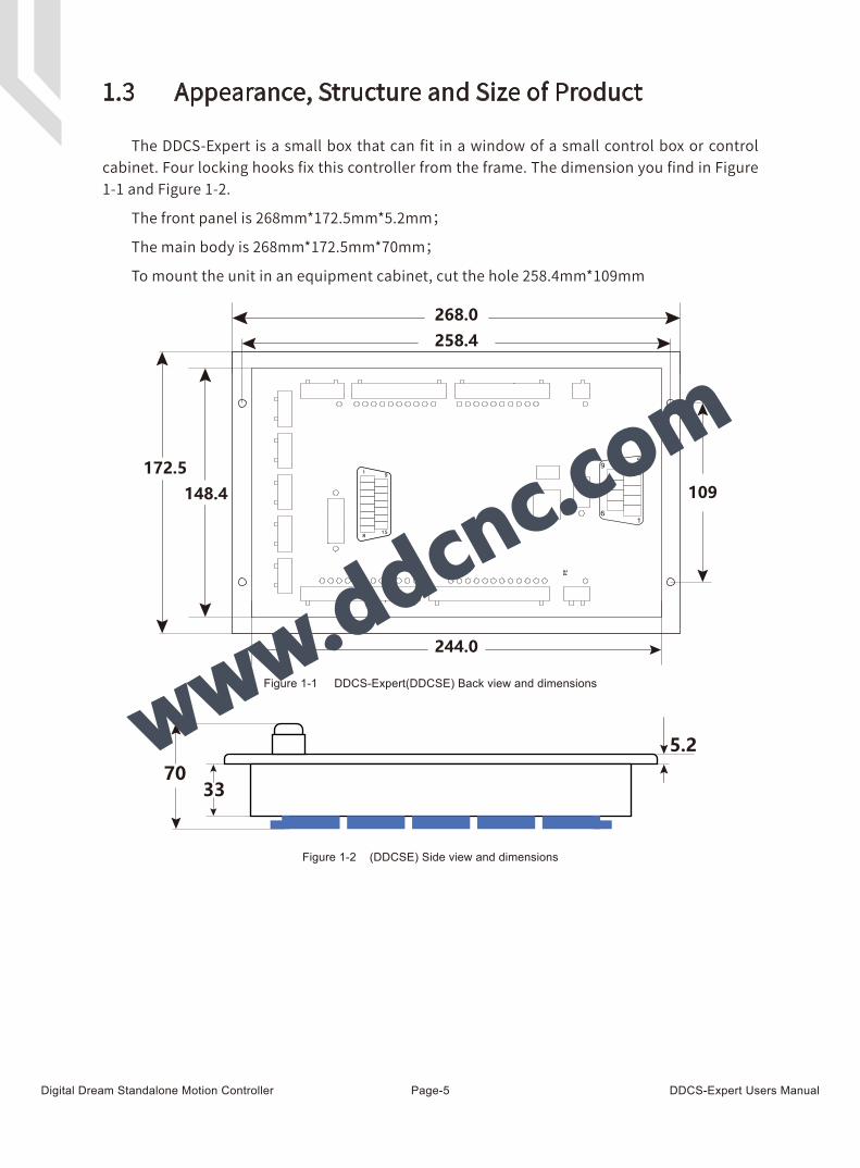
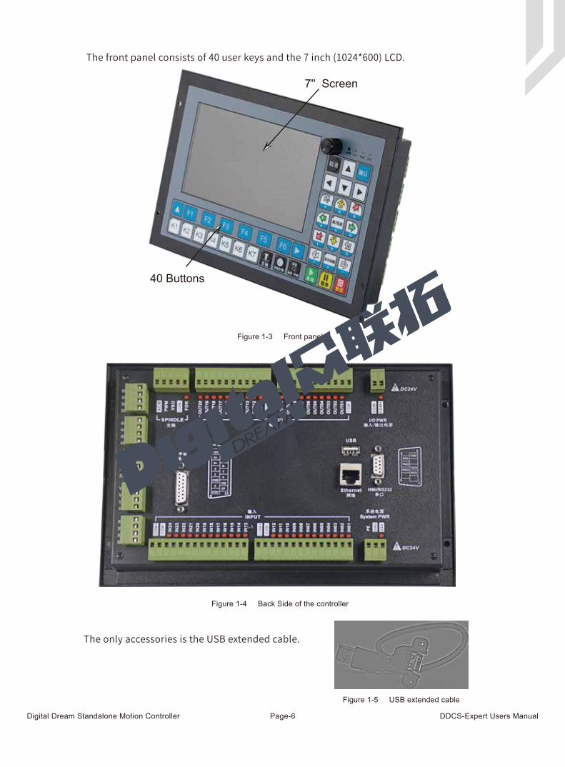
1.3 Appearance, Structure and Size of Product
The DDCS-Expert is a small box that can fit in a window of a small control box or control cabinet. Four locking hooks fix this controller from the frame. The dimension you find in Figure 1-1 and Figure 1-2.
The front panel is 268mm*172.5mm*5.2mm;
The main body is 268mm*172.5mm*70mm;
To mount the unit in an equipment cabinet, cut the hole 258.4mm*109mm
Figure 1-1 DDCS-Expert(DDCSE) Back view and dimensions
Figure 1-2 (DDCSE) Side view and dimensions
Digital Dream Standalone Motion Controller DDCS-Expert Users ManualPage-6
The front panel consists of 40 user keys and the 7 inch (1024*600) LCD.
Figure 1-3 Front panel
Figure 1-4 Back Side of the controller
Figure 1-5 USB extended cable
7'' Screen
40 Buttons
The only accessories is the USB extended cable.
Digital Dream Standalone Motion Controller DDCS-Expert Users ManualPage-7
When operating the DDCS, the users will come across some English abbreviations. Here a list with explanations:
FRO: Feed Rate Override
SRO: Spindle Rate Override
SJR: Jog Speed Setting
F: Feed rate, unit is mm/min
S: Spindle Speed, unit rev/min.
X: The coordinate code of the X axis.
Y: The coordinate code of the Y axis.
Z: The coordinate code of the Z axis.
A: The coordinate code of the A axis
B: The coordinate code of the B axis
BUSY: The system is busy. You still can adjust FRO and SRO
READY: READY mode, any operation can be done
RESET: Reset mode, controller is in “OFF” mode, no operation can be performed
CONT: Continuous mode, each axis can be manually jogged with the arrow keys
Step :Manual Step Mode,each axis can be jogged in defined steps
MPG: MPG mode. Operate the machine with the MPG (Manual Pulse Generator)
BUSY: Run G code. Auto is showing when file is processing
1.4 Explanation of Abbreviations
Keep away from exposure to moisture or water. This product contains sophisticated electronics and must not get wet.
Wiring warning: the IO input terminal of this controller supports equipment with source power (such as Inductive Proximity Switch ). When using this kind of equipment, pay attention to the polarity. Avoid the +terminal to be connect with GND. This controllers has analog output for spindle control (0-10V). Please avoid this terminal to ever connect with GND as damage to
the controller may occur.
Operation warning. Please observe all security measures when operating the machine. The ESTOP must be connected and properly labelled. In case of a problem, press the
E-stop at once to avoid damage to humans, animals and the equipment.
High voltage danger. The DDCS is connected to 24V DC. Obey and follow the electrici-ty safety rules of your country when connecting this equipment.
1.5 Notes and Warnings
Digital Dream Standalone Motion Controller DDCS-Expert Users ManualPage-8
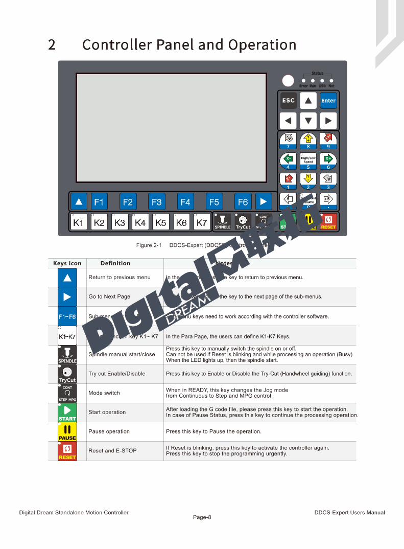
Figure 2-1 DDCS-Expert (DDCSE) Controller Panel
2 Controller Panel and Operation
Definition Notes
Return to previous menu
Go to Next Page
Sub-menu key F1~ F6
Extend function key K1~ K7
Keys Icon
~
~
Spindle manual start/close
Try cut Enable/Disable
Press this key to manually switch the spindle on or off. Can not be used if Reset is blinking and while processing an operation (Busy)When the LED lights up, then the spindle start.
In the Para Page, the users can define K1-K7 Keys.
Sub-menu keys need to work according with the controller software.
In the software, press the key to the next page of the sub-menus.
In the software, press the key to return to previous menu.
Press this key to Enable or Disable the Try-Cut (Handwheel guiding) function.
Mode switch When in READY, this key changes the Jog mode from Continuous to Step and MPG control.
Start operation After loading the G code file, please press this key to start the operation. In case of Pause Status, press this key to continue the processing operation.
Pause operation Press this key to Pause the operation.
Reset and E-STOP If Reset is blinking, press this key to activate the controller again. Press this key to stop the programming urgently.
Digital Dream Standalone Motion Controller DDCS-Expert Users ManualPage-9
Keys Icon Definition Notes
1: Cursor moves Up2: Parameter value increases3: Highlight the Selections
1: Cursor moves quickly2: Ratio/Values increase or decrease3: Push to Enter
1: Cursor moves Down2: Parameter value decreases3: Highlight the Selections
1: Cursor moves Left2: Moves through Para Kinds
1: Cursor moves Right2: Switch through Para Kinds
1: BackSpace Key2: Cancel or Delete Key
1: Confirm and Enter key
1: X axis moves right;2: Number “6”.
1: X axis moves left;2: Number “4”.
1: Y axis moves forward;2: Number “8”.
1: Y axis move backward;2: Number “2”.
1: Z axis Up2: Number “9”.
1: Z axis down2: Number “1”.
1: The 4th Axis rotates in inversion direction2: Number “3”.
1: The 4th Axis rotates in forward direction2: Number “7”.
1: The 5th Axis in forward direction2: The Symbol “-”.
1: The 5th Axis in inversion direction2: The Symbol “.”
1: High or Low Speed selection2: Number “5”.
1: Breakpoint resume active2: Number “0”.
In the Monitor Page, by turnning the knob, it can move amongdifferent column; after selecting the column, we can adjust thevalues fast and easily;In the Program page, by turnning the knob, we can select files quickly and press it to confirm;In the Parm and IO page, it also have the same functions.
In Monitor,the key can highlight the processing parametersFRO/SRO/SJR and so on; In Program/Param/IO page, it hightlight the selections.In Monitor, the key can highlight the processing parametersFRO/SRO/SJR and so on; Program/Param/IO page, it hightlight the selections.
In Param Page, the key moves among the Para Kinds; In IO page,It moves the cursor left.
In Param Page, the key moves among the Para Kinds; In IO page,It moves the cursor right.
By it we can come back to the main page, cancel and delte thevalue input, cancel the current action and so on.
In “CONT Mode”, the 4th axis will continuously move positive after pressing this key. In “STEP Mode” it will move positive in steps.
In “CONT Mode”, the Z axis will continuously move negative after pressing this key. In “STEP Mode” Z will move negative in steps.
In “CONT Mode”, the Z axis will continuously move positive after pressing this key. In “STEP Mode” Z will move positive in steps.
In “CONT Mode”, the Y axis will continuously move negative after pressing this key. In “STEP Mode” Y will move negative in steps.
In “CONT Mode”, the Y axis will continuously move positive after pressing this key. In “STEP Mode” Y will move positive in steps.
In “CONT Mode”, the X axis will Continuously move negative after pressing this key. In “STEP Mode” X will move negative in steps.
In “CONT Mode”, the X axis will Continuously move positive after pressing this key. In “STEP Mode” X will move positive in steps.
In “CONT Mode”, the X axis will Continuously move positive after pressing this key. In “STEP Mode” X will move positive in steps.
In “CONT Mode”, the 4th axis will continuously move negative after pressing this key. In “STEP Mode” it will move negative in steps. In “CONT Mode”, the 5th axis will continuously move positive after pressing this key. In “STEP Mode” it will move positive in steps. In “CONT Mode”, the 5th axis will continuously move negative after pressing this key. In “STEP Mode” it will move negative in steps.
When the LED lights up, it is in high-speed mode.
When the LED lights up,t he breakpoint resume is active.
Digital Dream Standalone Motion Controller DDCS-Expert Users ManualPage-10
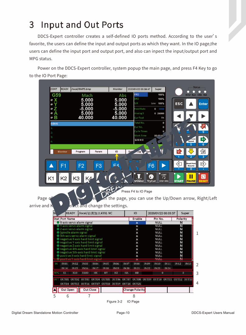
DDCS-Expert controller creates a self-defined IO ports method. According to the user’s favorite, the users can define the input and output ports as which they want. In the IO page,the users can define the input port and output port, and also can inpect the input/output port and MPG status.
Power on the DDCS-Expert controller, system popup the main page, and press F4 Key to go to the IO Port Page:
Page of the IO pop up as below.In the page, you can use the Up/Down arrow, Right/Left arrive and Knob to select and change the settings.
3 Input and Out Ports
1
2
3
4
5 6 7 8
Figure 3-1 Press F4 to IO Page
Figure 3-2 IO Page
Digital Dream Standalone Motion Controller DDCS-Expert Users ManualPage-11
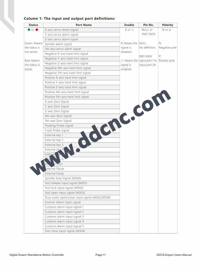
Column 1: The input and output port definitions:
Status Port Name Enable Pin No. Polarity
X or √ N or pNULL orIN01-IN24
Green: Meansthe status is not active.
Red: Means the status isactive.
X: Means thesignal is disabled.
√: Means thesignal is enabled.
NULL:No definition.
IN01-IN24:Input port 1 to Input port 24
N:Negative pole
P:Positive pole
or X-axis servo alarm signal
Y-axis servo alarm signal
Z-axis servo alarm signal
Spindle alarm signal
5th-axis servo alarm signal
Negative X-axis hard limit signal
Negative Y-axis hard limit signal
Negative Z-axis hard limit signal
Negative 4th-axis hard limit signal
Negative 5th-axis hard limit signal
Positive X-axis hard limit signal
Positive Y-axis hard limit signal
Positive Z-axis hard limit signal
Positive 4th-axis hard limit signal
Positive 5th-axis hard limit signal
X-axis Zero Signal
Y-axis Zero Signal
Z-axis Zero Signal
4th-axis Zero Signal
5th-axis Zero Signal
Floating Probe signal
Fixed Probe signal
External key 1
External key 2
External key 3
External key 4
External key 5
External key 6
External Start
External Pause
External Estop
Spindle Stop Signal (M300)
Tool release input signal (M301)
Tool lock input signal (M302)
Tool open input signal (M303)
Dust cover open/close input signal (M305/M306)
Inverter Alarm input signal
Customs alarm input signal 1
Customs alarm input signal 2
Customs alarm input signal 3
Customs alarm input signal 4
Customs alarm input signal 5
Tool close input signal (M304)

Digital Dream Standalone Motion Controller DDCS-Expert Users ManualPage-12
Important:
In the controller default setting, we already define the Output port 21 as the “Spindle forward rotation control signal”. On the controller wiring board, we didn’t name it as “Out21”, we name it as “FRO”.
Status Port Name Enable Pin No. Polarity
X or √ N or pNULL orOUT01-OUT21
Green: Meansthe status is not active.
Red: Means the status isactive.
X: Means thesignal is disabled.
√: Means thesignal is enabled.
NULL:No definition.
OUT1-OUT24:Output port 1to output 21
N:Negative pole
P:Positive pole
or Spindle forward rotation control signal
Spindle reverse rotation control signal
Spindle section speed 1
Spindle section speed 2
Spindle section speed 3
M8/M9 control signal
M10/M11 control signal
System alarm signal
System Running signal
System Brake signal
System ready signal
Tool release/lock signal (M154/M155)
Tool lauch/retract signal (M152/M153)
Front positioning/off signal (M156/M157)
Vacuum pump on/off output signal (M158/M159)
Dust cover open/close output signal (M150/M151)
Push cylinder open/close output signal (M160/M161)
Vacuum cleaner on/off output signal (M162/M163)
Left positioning on/off output signal (M164/M165)
Vacuum valve open/close output signal (M166/M167)
Multi-process 1 Open/close output signal (M168/M169)
Multi-process 2 Open/close output signal (M170/M171)
Multi-process 3 Open/close output signal (M172/M173)
Multi-process 4 Open/close output signal (M174/M175)
Cooling 1 on/off output signal (M176/M177)
Cooling 1 on/off output signal (M178/M179)
Figure 3-3 FOR Output Port

Digital Dream Standalone Motion Controller DDCS-Expert Users ManualPage-13
Show the input ports or output ports are on the short-circuit or not.
If the little block becomes Red,the according port is on the short-circuit; if it’s still black,the according port is not on the short-circuit.
For example, we define the IN01 as the “X-axis Zero Signal”, and when the X axis touched the limited switch, it will show as below:
But,the status is active, doesn’t mean that the according signal is active. For example,we reverse the signal’s polarity, and moves the X axis away from the limit switch, the status light and IO block show as below: the X-axis zero signal is active,and IN01 Block is not on,because IN01 is not conductiong with COM-.
Column 2 and Column 4:
Figure 3-4 Input 01 is conducting with COM-
Figure 3-5 The status is active but IN01 is not ON
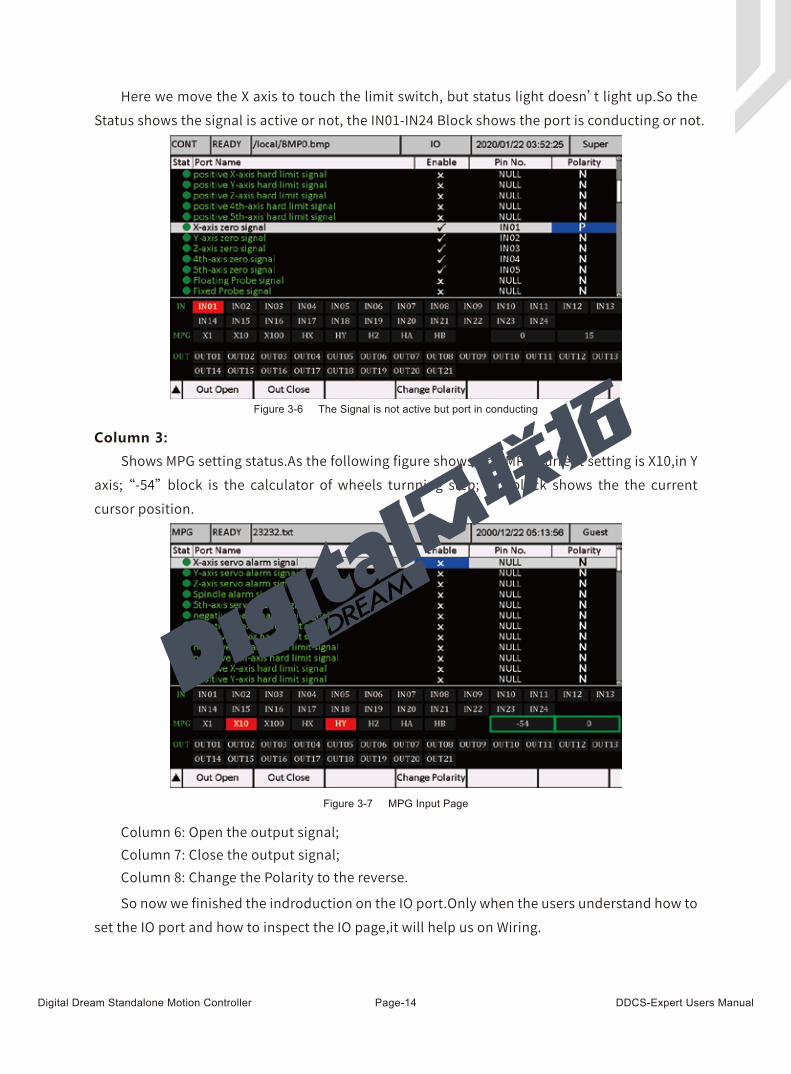
Digital Dream Standalone Motion Controller DDCS-Expert Users ManualPage-14
Shows MPG setting status.As the following figure shows, the MPG current setting is X10,in Y axis; “-54” block is the calculator of wheels turnning step; “0” block shows the the current cursor position.
So now we finished the indroduction on the IO port.Only when the users understand how to set the IO port and how to inspect the IO page,it will help us on Wiring.
Here we move the X axis to touch the limit switch, but status light doesn’t light up.So the Status shows the signal is active or not, the IN01-IN24 Block shows the port is conducting or not.
Column 3:
Column 6: Open the output signal;Column 7: Close the output signal;Column 8: Change the Polarity to the reverse.
Figure 3-6 The Signal is not active but port in conducting
Figure 3-7 MPG Input Page

Digital Dream Standalone Motion Controller DDCS-Expert Users ManualPage-15
4 Wiring
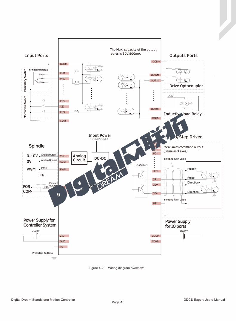
DDCS-Expert wiring board, there are about 7 parts as following:
1) System Power and IO Power supply input Ports; 2) Driver Signal output Ports; 3) Input and Output Ports; 4) Spindle Output Ports; 5) MPG Port; 6) Ethernet and USB interface; 7) HMI/RS232 interface.
4.1 Wiring Board Overview
Figure 4-1 Controller Wiring Ports Overview
SystemPower
IOPower
InputPort
OutputPort
Driver Signal Output
Analog Spindle/PWM SpindleStart & Stop
5P+5P-5D+5D-
4P+4P-4D+4D-
ZP+ZP-ZD+ZD-
YP+YP-YD+YD-
XP+XP-XD+XD-
COM+COM-
COM+COM-
IN24IN23IN22IN21IN20IN19IN18IN17IN16IN15IN14IN13
IN12IN11IN10IN09IN08IN07IN06IN05IN04IN03IN02IN01
24V
GND
PE
ACMPWMVSOCOM-
COM-
COM-
COM-
COM+
FOR
OUT20
OUT10OUT09OUT08OUT07OUT06OUT05OUT04OUT03OUT02OUT01
OUT19OUT18OUT17OUT16OUT15OUT14OUT13OUT12OUT11
1 5
6 9GND
GND
TXD2
RXD2TXD
1RXD
1
A-B-EP15 9
8
YIN4X10
A+B+XINZINX1005 1
GND
5V
COM-
HM
I/RS232Ethernet
MPG
USB
System Pow
er
I/O Power
OUTPU
T
INPU
T
Spindle
DC24V!
DC24V!
Digital Dream Standalone Motion Controller DDCS-Expert Users ManualPage-16
Input Power
Spindle
Power Supply forController System
Power Supplyfor IO ports
Input Ports
NPN Normal Open
Prox
imity
Sw
itch
Mec
hani
cal S
witc
h
Outputs Ports
Anolog Output
Protecting Earthing
0-10V0V Anolog Ground
PWM
ForwardRotation
Ground
PWM
FORCOM
The Max. capacity of the output ports is 30V,500mA.
Shieding Twist Cable
Shieding Twist Cable
YZ45 axes command output(Same as X axes)
Inductive load Relay
Servo/Step Driver
Drive Optocoupler
AnologCircuit DC-DC
Pulse+
Pulse-Direction+
Direction-
Figure 4-2 Wiring diagram overview
Digital Dream Standalone Motion Controller DDCS-Expert Users ManualPage-17
Pulse Signal Positive Output of the 5th Axis (5V)
Pulse Signal Negative Output of the 5th Axis (5V)
Direction Signal Positive Output of the 5th Axis (5V)
Direction Signal Negative Output of the 5th Axis (5V)
Pulse Signal Positive Output of the 4th Axis (5V)
Pulse Signal Negative Output of the 4th Axis (5V)
Direction Signal Positive Output of the 4th Axis (5V)
Direction Signal Negative Output of the 4th Axis (5V)
Pulse Signal Positive Output of the Z Axis (5V)
Pulse Signal Negative Output of the Z Axis (5V)
Direction Signal Positive Output of the Z Axis (5V)
Direction Signal Negative Output of the Z Axis (5V)
Pulse Signal Positive Output of the Y Axis (5V)
Pulse Signal Negative Output of the Y Axis (5V)
Direction Signal Positive Output of the Y Axis (5V)
Direction Signal Negative Output of the Y Axis (5V)
Pulse Signal Positive Output of the X Axis (5V)
Pulse Signal Negative Output of the X Axis (5V)
Direction Signal Positive Output of the X Axis (5V)
Direction Signal Negative Output of the X Axis (5V)
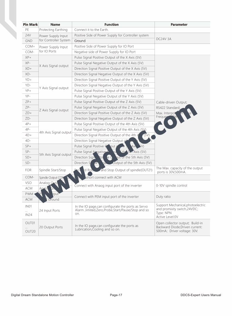
Pin Mark Name Function Parameter
COM-
COM+
24V
PE
GND
5P+
5P-
5D+
5D-
4P+
4P-
4D+
4D-
ZP+
ZP-
ZD+
ZD-
YP+
YP-
YD+
YD-
XP+
XP-
XD+
XD-
ACM
IN01…IN24
OUT01…OUT20
VSO
ACM
PWM
COM-
FOR
Protecting Earthing Connect it to the Earth.
DC24V 3A Power Supply Inputfor Controller System
Power Supply Inputfor IO Ports
X Axis Signal output
Y Axis Signal output
Z Axis Signal output
4th Axis Signal output
5th Axis Signal output
Spindle Start/Stop
Spindle Output COMMON
Analog Output
Analog Ground
PWM Output
PWM Ground
24 Input Ports
20 Output Ports
Forward Rotation and Stop Output of spindle(OUT21)
Cannot short connect with ACM
Connect with Anaog input port of the inverter
Connect with PEM input port of the inverter
Positive Side of Power Supply for Controller system
Ground
Positive Side of Power Supply for IO Port
Negative side of Power Supply for IO Port
In the IO page,can configurate the ports as Servo Alarm ,limited,Zero,Probe,Start/Pause/Stop and so on.
In the IO page,can configurate the ports as Lubrication,Cooling and so on.
Cable-driven Output;
RS422 Standard;
Max. Interpolation Pulse Frequency 1Mhz.
Support Mechanical,photoelectric and promixity switch,24VDC;Type: NPNActive Level:0V
Open collector output; Build-in Backward Diode;Driven current: 500mA; Driver voltage: 30V.
The Max. capacity of the output ports is 30V,500mA.
0-10V spindle control
Duty ratio
Digital Dream Standalone Motion Controller DDCS-Expert Users ManualPage-18
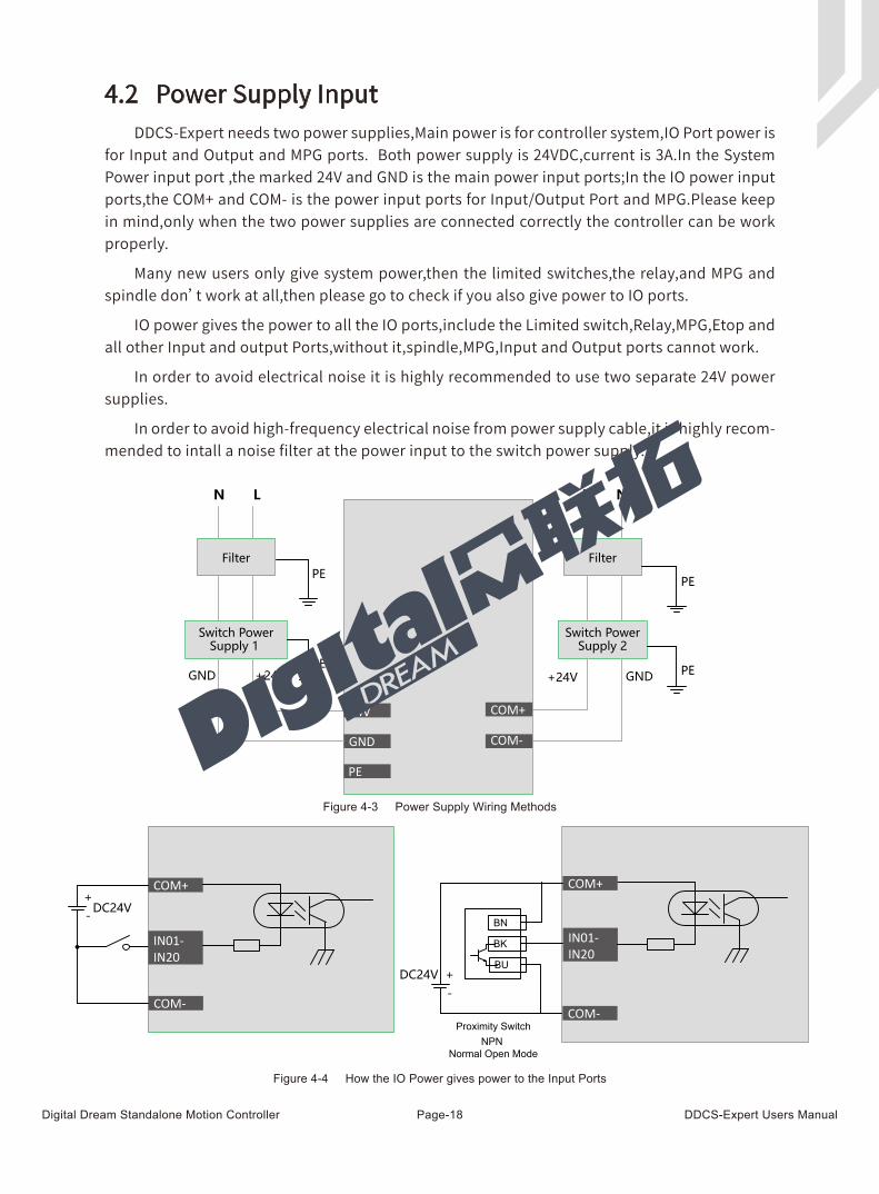
DDCS-Expert needs two power supplies,Main power is for controller system,IO Port power is for Input and Output and MPG ports. Both power supply is 24VDC,current is 3A.In the System Power input port ,the marked 24V and GND is the main power input ports;In the IO power input ports,the COM+ and COM- is the power input ports for Input/Output Port and MPG.Please keep in mind,only when the two power supplies are connected correctly the controller can be work properly.
Many new users only give system power,then the limited switches,the relay,and MPG and spindle don’t work at all,then please go to check if you also give power to IO ports.
IO power gives the power to all the IO ports,include the Limited switch,Relay,MPG,Etop and all other Input and output Ports,without it,spindle,MPG,Input and Output ports cannot work.
In order to avoid electrical noise it is highly recommended to use two separate 24V power supplies.
In order to avoid high-frequency electrical noise from power supply cable,it is highly recom-mended to intall a noise filter at the power input to the switch power supply.
4.2 Power Supply Input
GND
PE
24V
Filter
Switch PowerSupply 1
LN
+24VGNDPE
PE
COM-
COM+
Filter
Switch PowerSupply 2
L N
+24V GND PE
PE
DC24V +-
IN01-IN20
BN
BK
BU
Proximity SwitchNPN
Normal Open Mode
COM+
COM-
DC24V+-
IN01-IN20
COM+
COM-
Figure 4-3 Power Supply Wiring Methods
Figure 4-4 How the IO Power gives power to the Input Ports
Digital Dream Standalone Motion Controller DDCS-Expert Users ManualPage-19
24V
GND
PE
COM
-
COM
+
1
5
6
9 GNDGNDTXD2RXD2
TXD1RXD1
HMI/RS232
System Power
I/O Power
DC24V!
DC24V!
Earthing
L I N E
L O A D
G N
L’ G’
N’
EMI
FILT
ER11
5/25
0V60
/50H
z
CX
CX
CY
CY
L
LL
CE
RoH
S
L I N E
L O A D
G N
L’ G’
N’
EMI
FILT
ER11
5/25
0V60
/50H
z
CX
CX
CY
CY
L
LL
CE
RoH
S
EMI Filter
EMI Filter
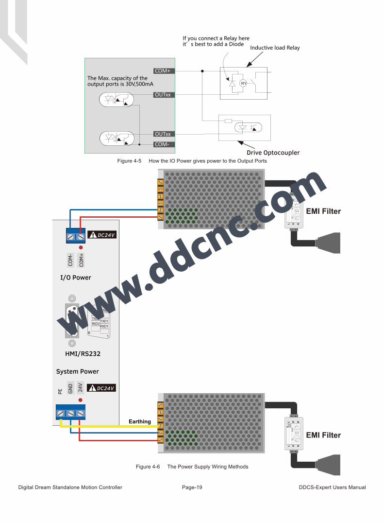
The Max. capacity of the output ports is 30V,500mA
If you connect a Relay hereit’s best to add a Diode
COM+
COM-
OUTxx
OUTxx
Inductive load Relay
Drive OptocouplerFigure 4-5 How the IO Power gives power to the Output Ports
Figure 4-6 The Power Supply Wiring Methods
Digital Dream Standalone Motion Controller DDCS-Expert Users ManualPage-20
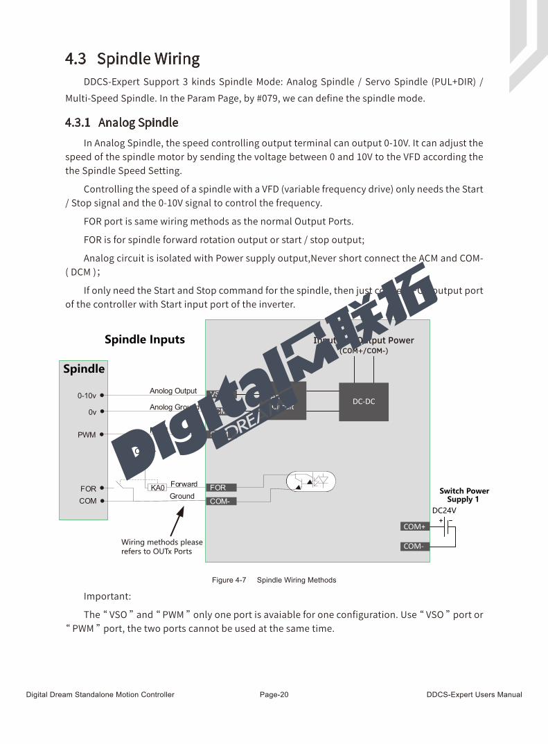
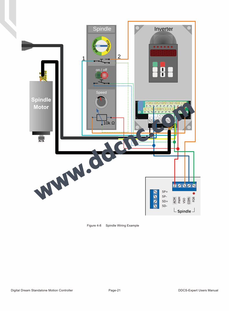
4.3 Spindle Wiring
4.3.1 Analog Spindle
Switch PowerSupply 1
Spindle Inputs
Spindle
COM-
COM+
DC24V
Wiring methods pleaserefers to OUTx Ports
Input and Output Power
AnologCircuit
(COM+/COM-)
DC-DC
Figure 4-7 Spindle Wiring Methods
In Analog Spindle, the speed controlling output terminal can output 0-10V. It can adjust the speed of the spindle motor by sending the voltage between 0 and 10V to the VFD according the the Spindle Speed Setting.
Controlling the speed of a spindle with a VFD (variable frequency drive) only needs the Start / Stop signal and the 0-10V signal to control the frequency.
FOR port is same wiring methods as the normal Output Ports.
FOR is for spindle forward rotation output or start / stop output;
Analog circuit is isolated with Power supply output,Never short connect the ACM and COM- ( DCM );
If only need the Start and Stop command for the spindle, then just connect FOR output port of the controller with Start input port of the inverter.
Important:
The “ VSO ” and “ PWM ” only one port is avaiable for one configuration. Use “ VSO ” port or “ PWM ” port, the two ports cannot be used at the same time.
DDCS-Expert Support 3 kinds Spindle Mode: Analog Spindle / Servo Spindle (PUL+DIR) / Multi-Speed Spindle. In the Param Page, by #079, we can define the spindle mode.
Digital Dream Standalone Motion Controller DDCS-Expert Users ManualPage-21
Figure 4-8 Spindle Wiring Example
5P+5P-5D+5D-
ACM
PWM
VSO
COM
-FO
R
Spindle
SpindleMotor
V W

Digital Dream Standalone Motion Controller DDCS-Expert Users ManualPage-22
In Param Page #079, we set the “ Spindle interface type ” to “ Plu/dir ”, and In Param Page #080 define “ Spindle mapping axis ” to the axis as you need,this axis is defined to be a servo spindle.
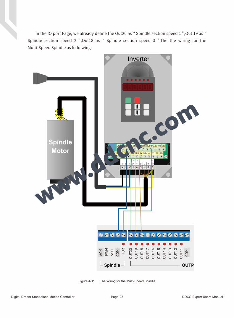
There are 3 parameters related to the Multi-speed spindle:
#079 -- “ Spindle interface type ” ; Here we need to set it to “ Multi-speed ”;
#088 -- “ Multi-speed section counts ”; The section count value range is 2-8, the users can set 2-8 different spindle speed.
#082 -- “ Max. Spindle Speed ”.
For example, if the #088 set as 8,and the #082 is 24000, then if the current section is 2, the current spindle speed is 6000; if the curernt section is 3, the current spindle speed is 9000; If the current section is 4, the current spindle speed is 12000, ect...
There are 3 Output ports related to the Multi-speed spindle, the users need to define them to the according output ports.
Spindle section speed 1 = S1 ;
Spindle section speed 2 = S2 ;
Spindle section speed 3 = S3 ;
4.3.2 Servo Spindle (PLUSE/DIRECTION)
4.3.3 Multi-Speed Spindle
Multi-speed section Spindle section Output
2 S1
3,4 S1,S2
4-8 S1,S2.S3
Current Section
1
Output Status S3 S2 S1
0 0 0
2 0 0 1
3 0 1 0
4 0 1 1
5 1 0 0
6 1 0 1
7 1 1 0
8 1 1 1
Note: 1 is output,0 is no output.
Figure 4-9 The relationship between the Multi-speed section and Spindle section output
Figure 4-10 The Relationship between the Current Section and Output Status
Digital Dream Standalone Motion Controller DDCS-Expert Users ManualPage-23
In the IO port Page, we already define the Out20 as “ Spindle section speed 1 ”,Out 19 as “ Spindle section speed 2 ”,Out18 as “ Spindle section speed 3 ”.The the wiring for the Multi-Speed Spindle as follolwing:
Figure 4-11 The Wiring for the Multi-Speed Spindle
SpindleMotor
V W
ACM
PWM
VSO
COM
-
COM
-
FOR
OUT2
0OU
T19
OUT1
8OU
T17
OUT1
6OU
T15
OUT1
4OU
T13
OUT1
2OU
T11
OUTPUTSpindle
Digital Dream Standalone Motion Controller DDCS-Expert Users ManualPage-24
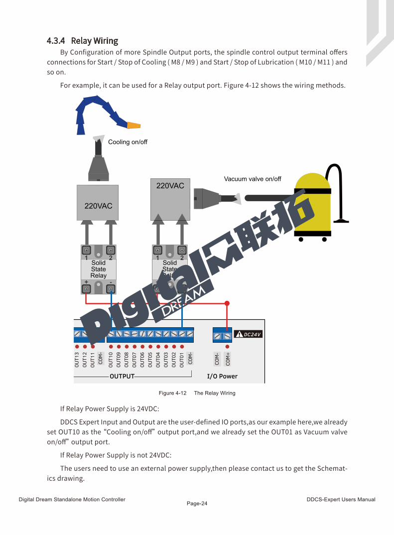
By Configuration of more Spindle Output ports, the spindle control output terminal offers connections for Start / Stop of Cooling ( M8 / M9 ) and Start / Stop of Lubrication ( M10 / M11 ) and so on.
For example, it can be used for a Relay output port. Figure 4-12 shows the wiring methods.
If Relay Power Supply is 24VDC:
DDCS Expert Input and Output are the user-defined IO ports,as our example here,we already set OUT10 as the “Cooling on/off” output port,and we already set the OUT01 as Vacuum valve on/off” output port.
If Relay Power Supply is not 24VDC:
The users need to use an external power supply,then please contact us to get the Schemat-ics drawing.
4.3.4 Relay Wiring
SolidStateRelay
SolidStateRelay
220VAC
220VAC
Cooling on/off
Vacuum valve on/off
+
1 2 1 2
- + -
DC24V!
COM
-
COM
-
COM
-
COM
+
OUT1
0OU
T09
OUT0
8OU
T07
OUT0
6OU
T05
OUT0
4OU
T03
OUT0
2OU
T01
OUT1
3OU
T12
OUT1
1
I/O PowerOUTPUT
Figure 4-12 The Relay Wiring
Digital Dream Standalone Motion Controller DDCS-Expert Users ManualPage-25
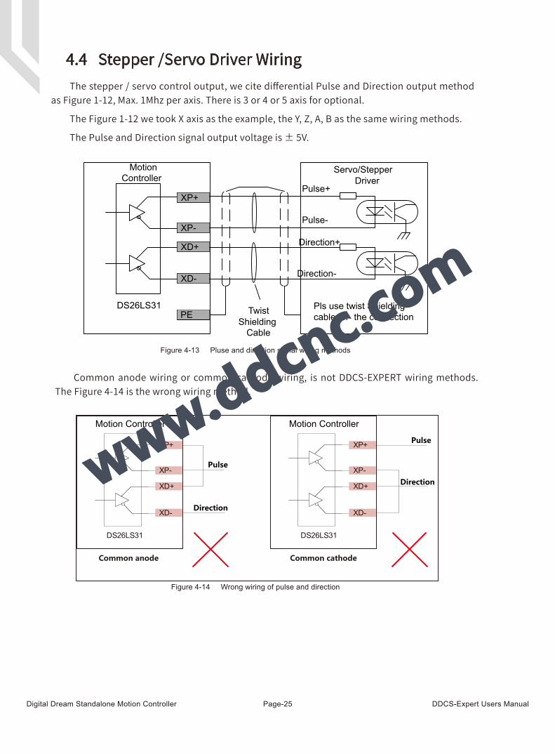
4.4 Stepper /Servo Driver WiringThe stepper / servo control output, we cite differential Pulse and Direction output method
as Figure 1-12, Max. 1Mhz per axis. There is 3 or 4 or 5 axis for optional.
The Figure 1-12 we took X axis as the example, the Y, Z, A, B as the same wiring methods.
The Pulse and Direction signal output voltage is ± 5V.
Pulse+
Twist Shielding
Cable
Pls use twist Shieldingcable for the connection
XP-
XD+
XD-
XP+
PE
Pulse-
Direction+
Direction-
Servo/Stepper Driver
DS26LS31
Motion Controller
Motion Controller Motion Controller
Pulse
Direction
Pulse
Direction
Common anode Common cathode
Figure 4-13 Pluse and direction signal wiring methods
Figure 4-14 Wrong wiring of pulse and direction
Common anode wiring or common cathode wiring, is not DDCS-EXPERT wiring methods. The Figure 4-14 is the wrong wiring method.
Digital Dream Standalone Motion Controller DDCS-Expert Users ManualPage-26
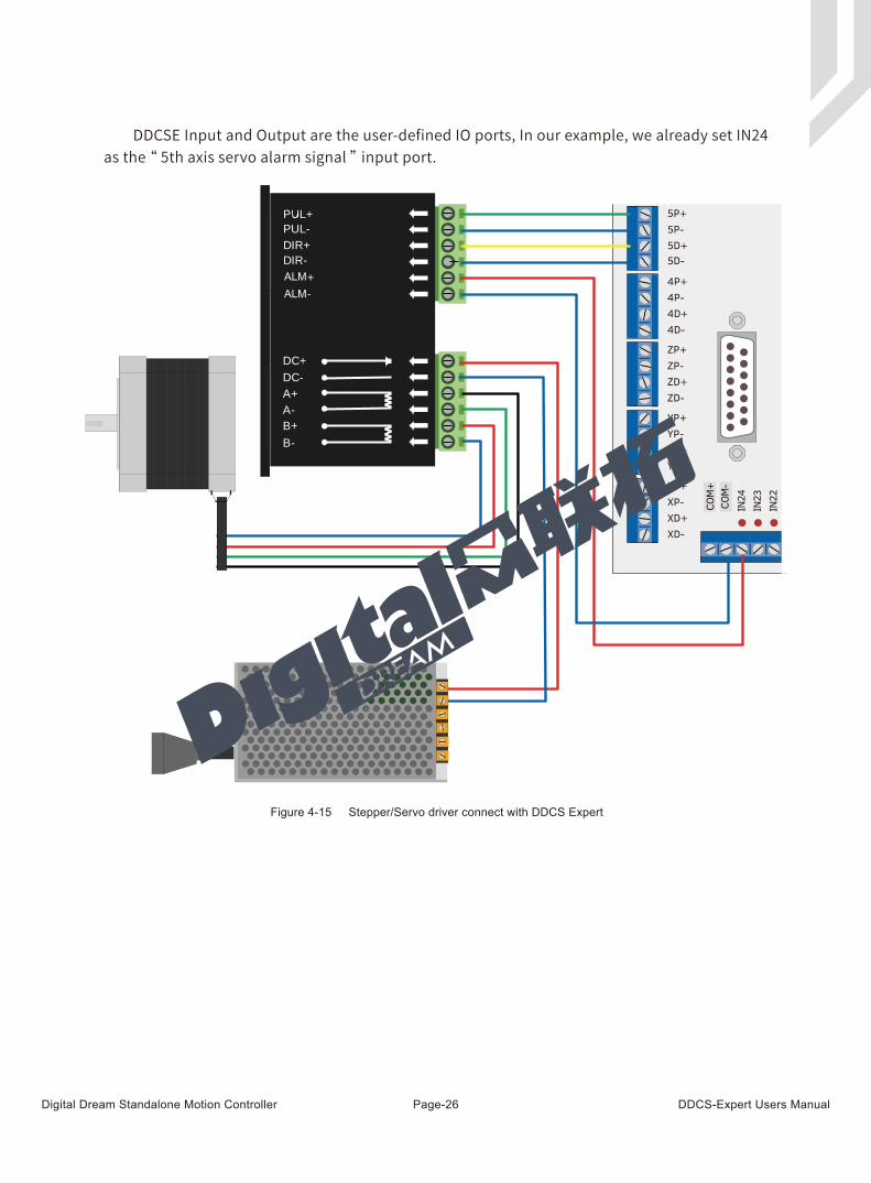
DDCSE Input and Output are the user-defined IO ports, In our example, we already set IN24 as the “ 5th axis servo alarm signal ” input port.
Figure 4-15 Stepper/Servo driver connect with DDCS Expert
ALMALM
5P+5P-5D+5D-
4P+4P-4D+4D-
ZP+ZP-ZD+ZD-
YP+YP-YD+YD-
XP+XP-XD+XD-
COM
+CO
M-
IN24
IN23
IN22
Digital Dream Standalone Motion Controller DDCS-Expert Users ManualPage-27
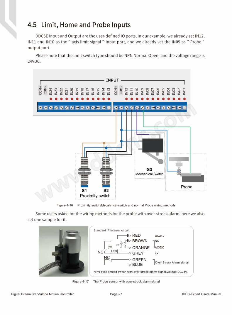
4.5 Limit, Home and Probe InputsDDCSE Input and Output are the user-defined IO ports, In our example, we already set IN12,
IN11 and IN10 as the “ axis limit signal ” Input port, and we already set the IN09 as “ Probe ” output port.
Please note that the limit switch type should be NPN Normal Open, and the voltage range is 24VDC.
Some users asked for the wiring methods for the probe with over-strock alarm, here we also set one sample for it.
Figure 4-16 Proximity switch/Mecahnical switch and normal Probe wiring methods
Figure 4-17 The Probe sensor with over-strock alarm signal
Proximity switchS1 S2
S3Mechanical Switch
Probe
COM
+CO
M-
COM
+CO
M-
IN24
IN23
IN22
IN21
IN20
IN19
IN18
IN17
IN16
IN15
IN14
IN13
IN12
IN11
IN10
IN09
IN08
IN07
IN06
IN05
IN04
IN03
IN02
IN01
INPUT
NC
RED DC24V
NO
AC/DC
0V
Over Strock Alarm signal
BROWN
ORANGEGREYGREENBLUE
NC
LED
I/F
Standard IF internal circuit
NPN Type limited switch with over-strock alarm signal,voltage DC24V.
Digital Dream Standalone Motion Controller DDCS-Expert Users ManualPage-28
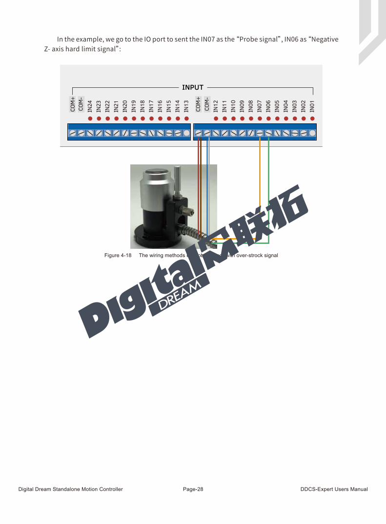
In the example, we go to the IO port to sent the IN07 as the “Probe signal”, IN06 as “Negative Z- axis hard limit signal”:
Figure 4-18 The wiring methods of Probe sensor with over-strock signal
COM
+CO
M-
COM
+CO
M-
IN24
IN23
IN22
IN21
IN20
IN19
IN18
IN17
IN16
IN15
IN14
IN13
IN12
IN11
IN10
IN09
IN08
IN07
IN06
IN05
IN04
IN03
IN02
IN01
INPUT
Digital Dream Standalone Motion Controller DDCS-Expert Users ManualPage-29
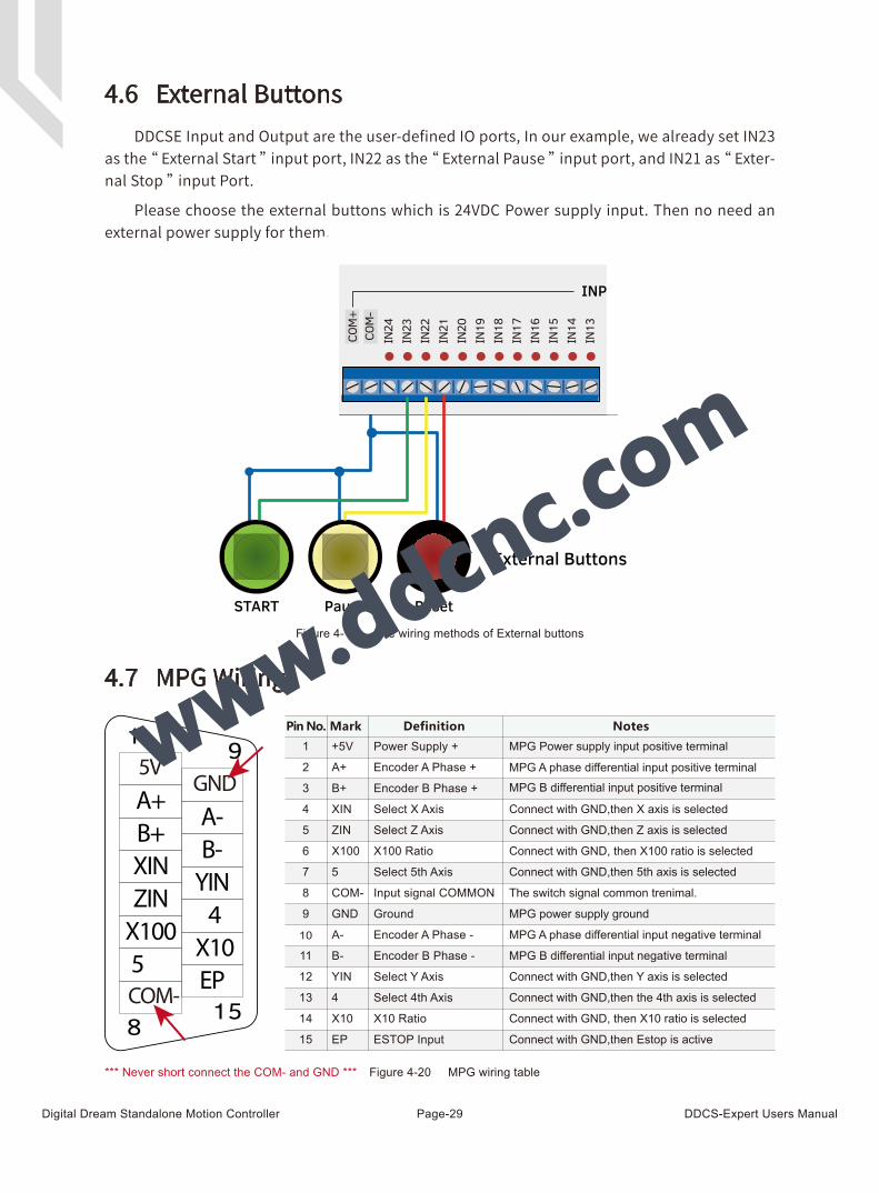
4.6 External ButtonsDDCSE Input and Output are the user-defined IO ports, In our example, we already set IN23
as the “ External Start ” input port, IN22 as the “ External Pause ” input port, and IN21 as “ Exter-nal Stop ” input Port.
Please choose the external buttons which is 24VDC Power supply input. Then no need an external power supply for them.
Figure 4-19 The wiring methods of External buttons
*** Never short connect the COM- and GND ***
4.7 MPG Wiring
Figure 4-20 MPG wiring table
A-B-
EP15
9
8
YIN4X10
A+B+XINZINX1005
1
GND5V
COM-
5
X10
X100
XIN
YIN
ZIN
4
B+
B-
A+
A-
COM-
+5V
EP
GND
7
14
6
4
12
5
13
3
11
2
10
8
1
15
9
X100 Ratio
Select X Axis
Select Z Axis
Encoder B Phase -
Encoder A Phase -
Encoder B Phase +
Encoder A Phase +
Input signal COMMON
Ground
X10 Ratio
Select Y Axis
Select 4th Axis
Select 5th Axis
ESTOP Input
Power Supply +Pin No. Definition Notes
MPG power supply ground
Connect with GND,then Z axis is selected
Connect with GND,then 5th axis is selected
Connect with GND,then X axis is selected
Connect with GND,then Y axis is selected
Connect with GND,then the 4th axis is selected
Connect with GND,then Estop is active
MPG Power supply input positive terminal
MPG B differential input positive terminalMPG A phase differential input positive terminal
MPG B differential input negative terminal
MPG A phase differential input negative terminal
The switch signal common trenimal.
Mark
Connect with GND, then X100 ratio is selected
Connect with GND, then X10 ratio is selected
START Pause Reset
External Buttons
COM
+CO
M-
IN24
IN23
IN22
IN21
IN20
IN19
IN18
IN17
IN16
IN15
IN14
IN13
INPUT
Digital Dream Standalone Motion Controller DDCS-Expert Users ManualPage-30
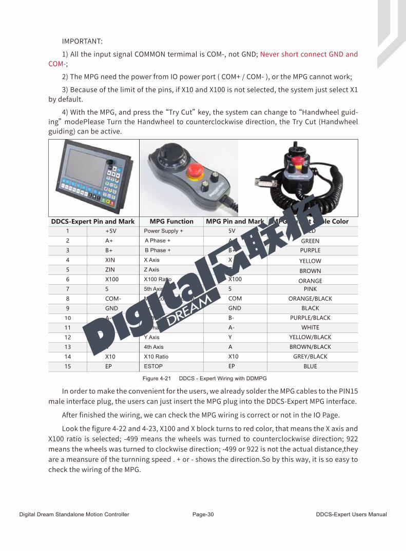
Figure 4-21 DDCS - Expert Wiring with DDMPG
IMPORTANT:
1) All the input signal COMMON termimal is COM-, not GND; Never short connect GND and COM-;
2) The MPG need the power from IO power port ( COM+ / COM- ), or the MPG cannot work;
3) Because of the limit of the pins, if X10 and X100 is not selected, the system just select X1 by default.
4) With the MPG, and press the “Try Cut” key, the system can change to “Handwheel guid-ing” modePlease Turn the Handwheel to counterclockwise direction, the Try Cut (Handwheel guiding) can be active.
In order to make the convenient for the users, we already solder the MPG cables to the PIN15 male interface plug, the users can just insert the MPG plug into the DDCS-Expert MPG interface.
After finished the wiring, we can check the MPG wiring is correct or not in the IO Page.
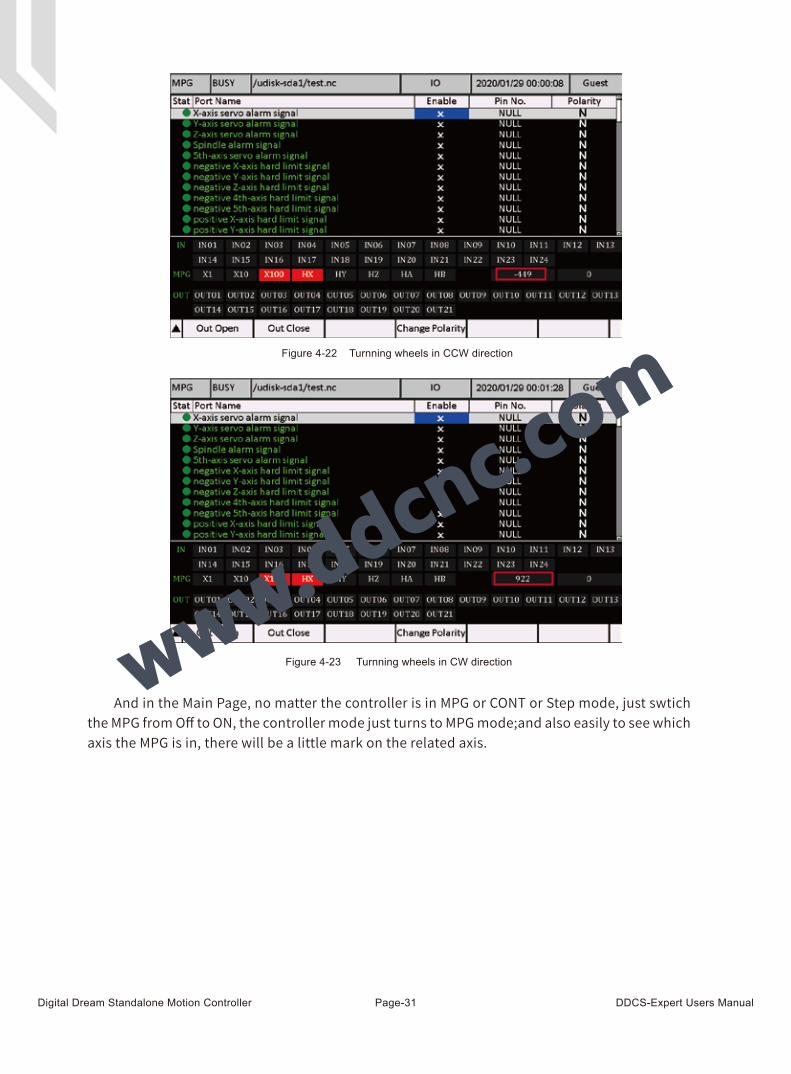
Look the figure 4-22 and 4-23, X100 and X block turns to red color, that means the X axis and X100 ratio is selected; -499 means the wheels was turned to counterclockwise direction; 922 means the wheels was turned to clockwise direction; -499 or 922 is not the actual distance,they are a meansure of the turnning speed . + or - shows the direction.So by this way, it is so easy to check the wiring of the MPG.
DDCS-Expert Pin and Mark
5
X10
X100
X
Y
Z
X100 Ratio
X Axis
Z Axis
5th Axis
MPG common COM-
A
A+
A-
B+
B-
A Phase -
B Phase -
A Phase +
B Phase +
COM
5V
EP
X10 Ratio
Y Axis
4th Axis
ESTOP
GNDGround
Power Supply +MPG Function MPG Pin and Mark MPG Output Cable Color
YELLOW
YELLOW/BLACK
BROWN
BROWN/BLACK
PINK
ORANGE/BLACK
BLACK
GREY/BLACK
ORANGE
BLUE
GREEN
WHITE
PURPLE
PURPLE/BLACK
RED
5
X10
X100
XIN
YIN
ZIN
4
B+
B-
A+
A-
COM-
+5V
EP
GND
7
14
6
4
12
5
13
3
11
2
10
8
1
15
9
DDMPG
Digital Dream Standalone Motion Controller DDCS-Expert Users ManualPage-31
And in the Main Page, no matter the controller is in MPG or CONT or Step mode, just swtich the MPG from Off to ON, the controller mode just turns to MPG mode;and also easily to see which axis the MPG is in, there will be a little mark on the related axis.
Figure 4-22 Turnning wheels in CCW direction
Figure 4-23 Turnning wheels in CW direction
Digital Dream Standalone Motion Controller DDCS-Expert Users ManualPage-32
GND1
TXD1
GND2
TXD2
RXD2
RXD1 Serial port 1 Receiver
Serial port 1 Sender
Serial port 1 Ground
Serial port 2 Receiver
Serial port 2 Sender
Serial port level is 232
Serial port level is 232
Serial port 2 Ground
2
3
4
5
6
7
8
9
1Pin No. Definition NotesMark
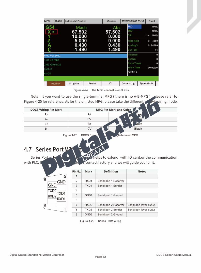
4.7 Series Port Wiring
Figure 4-26 Series Ports wiring
Note: It you want to use the single-terminal MPG ( there is no A-B-MPG ), please refer to Figure 4-25 for reference. As for the unlisted MPG, please take the differential MPG wiring mode.
Series Port is for Modbus extension, it helps to extend with IO card,or the communication with PLC. If some users need it please contact factory and we will guide you for it.
B-
A-
B+
A+ A+ Green0V BlackB+ White0V Black
DDCS Wiring Pin Mark MPG Pin Mark and Color
Figure 4-25 DDCS Expert Wiring with Single-terminal MPG
1
5
6
9 GNDGNDTXD2RXD2
TXD1RXD1
Figure 4-24 The MPG channel is on X axis
Digital Dream Standalone Motion Controller DDCS-Expert Users ManualPage-33
5 Software and Operation
1. Simulation2. Probe
1. Floating Probe
3. Fixed Probe4. Mult Probe5. XY Teach
1. X Go Zero2. Y Go Zero3. Z Go Zero4. 4th Go Zero5. 5th Go Zero
6. Z Teach
3. Go Work Zero
1. X Go Home2. Y Go Home3. Z Go Home4. 4th Go Home5. 5th Go Home
6. All Go Zero
1. Clear X2. Clear Y3. Clear Z4. Clear 4th5. Clear 5th
6. All Go Home
4. Go Home
6. Break Run
5. Clear
1. Start Line2. Power Resume3. Pause Resume
6. Clear All
1. Set X2. Middle X3. Set Y4. Middle Y
7. Manual
1. Select Coord2. Clear X3. Clear Y4. Clear Z5. Z step6. Deeper
1. Move up2. Clear 4th
... ...
8. Coord Set
1. Execute(1)
6. Execute(6)
3. Clear 5th
9. MDI
1. Clear Record
6. 3Pts
10. Middle
12. Sort Process
11. Work Record
1. Up2. Down3. New4. Del5. Times 6. Load List
1. Export List2. Del List
2. To U Disk
Monitor Program Page
1. Switch Disks2. Del3. Rename4. Copy to U Disk6. Simulate
1. Copy2. Paste3. Edit
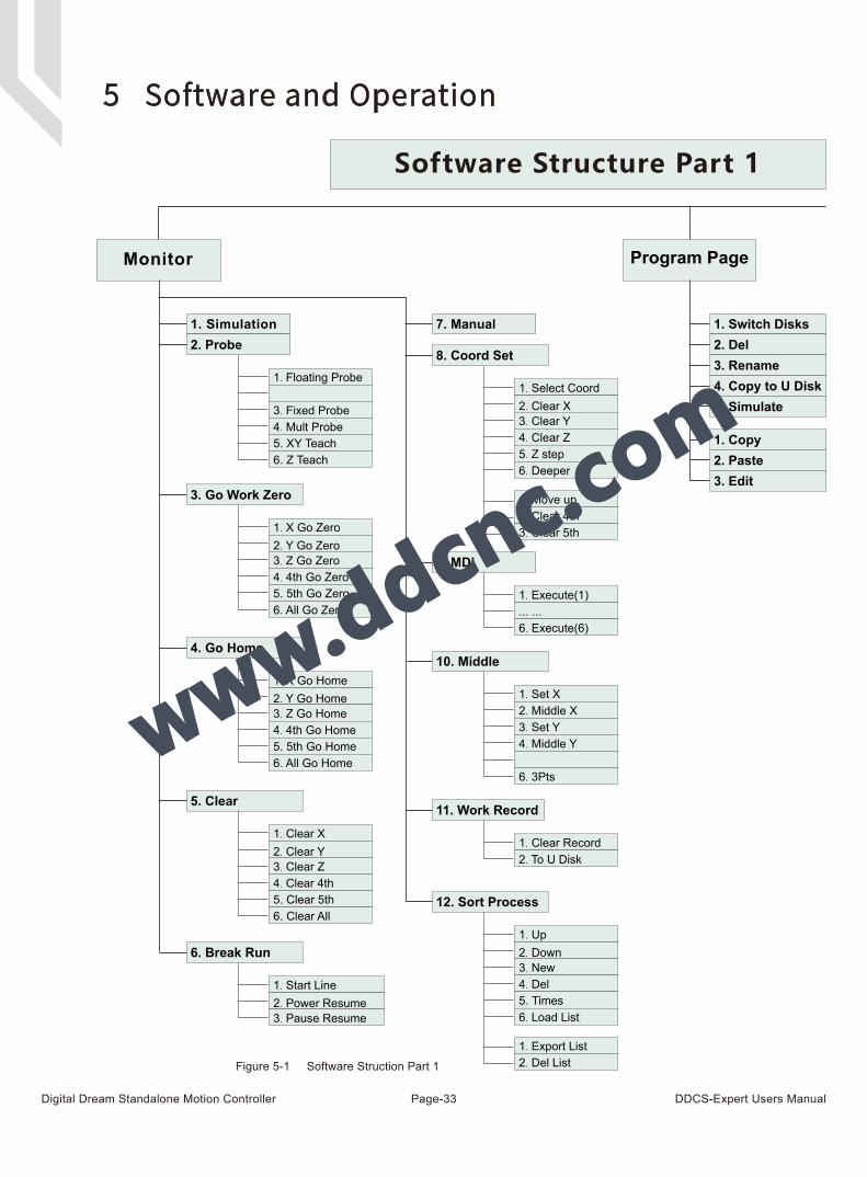
Software Structure Part 1
Figure 5-1 Software Struction Part 1
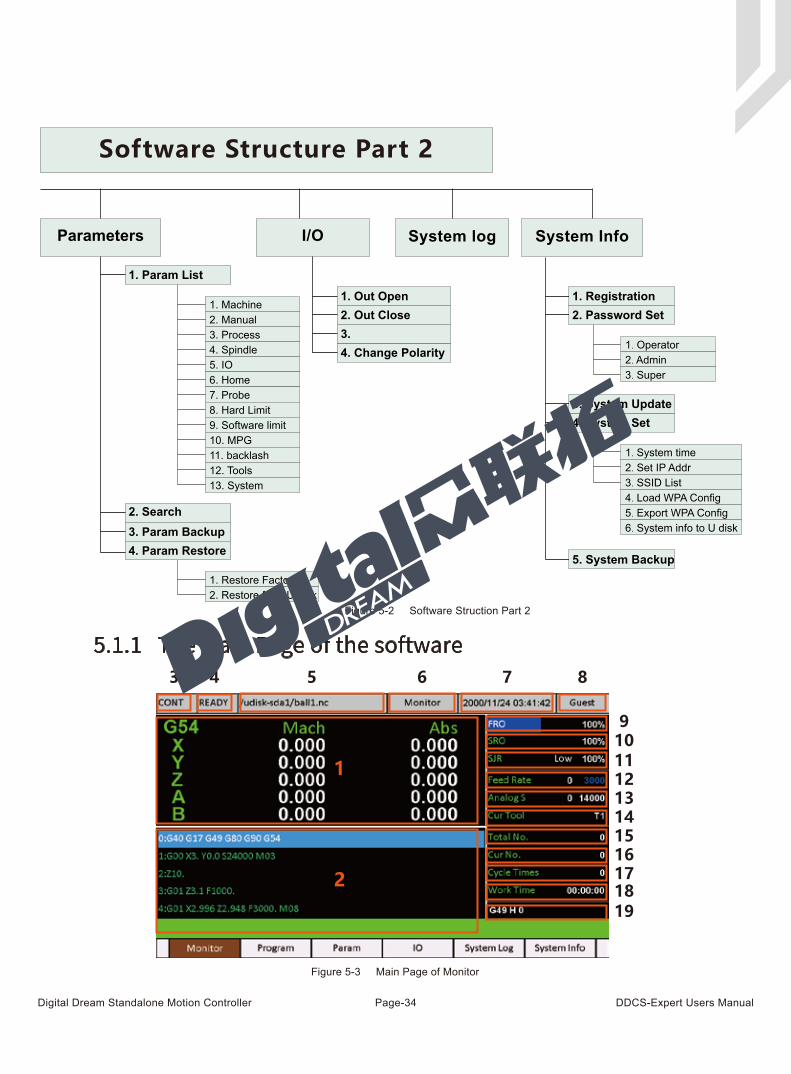
Digital Dream Standalone Motion Controller DDCS-Expert Users ManualPage-34
5.1.1 The Main Page of the software
Parameters I/O
3.
1. Out Open2. Out Close
4. Change Polarity
System log
1. Param List
2. Search3. Param Backup4. Param Restore
1. Restore Factory2. Restore from U-disk
4. Spindle
1. Machine2. Manual3. Process
5. IO6. Home7. Probe8. Hard Limit9. Software limit10. MPG11. backlash12. Tools13. System
System Info
1. Registration2. Password Set
3. System Update4. System Set
5. System Backup
1. Operator2. Admin
1. System time2. Set IP Addr3. SSID List4. Load WPA Config5. Export WPA Config6. System info to U disk
3. Super
Software Structure Part 2
1
2
3 4 5 6 7 8
910111213141516171819
Figure 5-2 Software Struction Part 2
Figure 5-3 Main Page of Monitor
Digital Dream Standalone Motion Controller DDCS-Expert Users ManualPage-35
The Figure 5-3 shows the Main Page of the DDCS Expert. It is divided into status column, coordinate display column, basic parameter column, and notification column. In total, it is divided into 19 sections in detail. Here the detailed description of the 19 sections :
1、 XYZAB Coordinate
This column shows the Machine coordinate and Current coordinate value of XYZAB axis. The display range is -99999.999 ~ +99999.999 in mm;
2、 Status
When the controller runs the G code file, it will show the current operation line and opera-tion status.
3、 Feed status
This window shows the feed status of CONT.
AUTO: displayed while processing and executing the G code file
CONT: indicates Jog CONTINUOUS. You can Jog manually with the “ - ”or “ + ” keys of X Y Z and A and B.
STEP: Indicates STEP Jog mode.You can Jog manually in a defined distance with the “ - ”or
“ + ” keys of X Y Z and A and B.
MPG: Only when shift to MPG mode, you can operate MPG on the controller.
4、 Operating Status
This column shows the operating state. The status and implications can be displayed as follows:
Busy: Operation is running
Reset: Reset flashing = controller not active. To activate the controller click Reset
READY: Ready state. Controller is ready and all operations can be performed
5、 Processing file
This column shows the name of the processing file and file path.
6、Software Interface
This column shows the current software interface.
7、Date and working time
This column shows the date and working time. The Date can be reset.
Digital Dream Standalone Motion Controller DDCS-Expert Users ManualPage-36
8、 User ’s rights
This controller Support 4 kinds operation rights: visitor, operator, admin, super admin.T his column shows the current rights.
9、FRO
FRO controls the Feed Speed. Click FRO till FRO is highlighted. Use rotary button ( knob ) or Up / Down keys to adjust the Feed Speed in 1% increments, the range is 0% - 120%.
10、 SRO
SRO controls the Spindle Speed. Click FRO till SRO is highlighted, use rotary button(knob) or Up / Down keys adjust the Spindle Speed in 1% increments, the range is 0% - 150%.
11、 SJR / Jog Step
Press the Key, the feed status shift among in CONT, STEP and MPG.
When the controller mode is CONT and MPG, it will show the SJR.
SJR controls the jogging of the machine. Turnning the rotary button (knob) till SJR is high-lighted. Turnning rotary button (knob) or Up / Down keys to adjust the speed in 1% increments. The range is 0% - 120%. Press knob to enter the setting.
When in Step Mode, Pressing the rotary button (knob) or keys to change between the 4 distances 0.001 / 0.01 / 0.1 / 1 or define any distance.
When in MPG mode you can use the MPG to jog the machine
High/Low Speed: Manually speed
12、 Feed speed
F stands for Feed Speed. Turnning the rotary button or clicking up or down keys till F is highlighted, click button or Enter to modify and edit the value you want.
Here you can Ignore the F value, then the system will use the F value from Gcode file, and also you can define a default F value. When the color the number is blue, then the system uses the default value, if the color is white, the system uses F speed from G-cdode file.
13、 Speed of spindle
Anolog S stands for Spindle Speed. Turnning the rotary button or clicking up or down keys till Analog S is highlighted, click button or Enter to modify and edit the value you want.
Here you can Ignore the S value, then the system will use the S value from Gcode file, and also you can define a defalt S value.
When the color the number is blue, then the system uses the default value,if the color is white, the system uses S speed from G-cdode file.
Digital Dream Standalone Motion Controller DDCS-Expert Users ManualPage-37
14、 Cur Tool :
This column display the current Tool No.
15、 Total No.
Total Machinning No.
16、 Cur No.
Current Machinning No.
When the Gcode file changed,t he number will be cleared to 0.
When excute M47 or M30, the counter will add 1, the working time cleared to 0; When M47 reached to the cycle times, the system pauses,and the number cleared to 0.
17、 Cycle Times
Set a limited number of cycle times.
When system excute M47 from cycle Gcode file,and M47 excuting time reaches to cycle times which you set, system just pause itself, and clear current machinning No.
18.Work Time
The working time for the current G-code file.
When restart the program,it will start to count.
19. G49 H 0
The compensation setting.
Digital Dream Standalone Motion Controller DDCS-Expert Users ManualPage-38
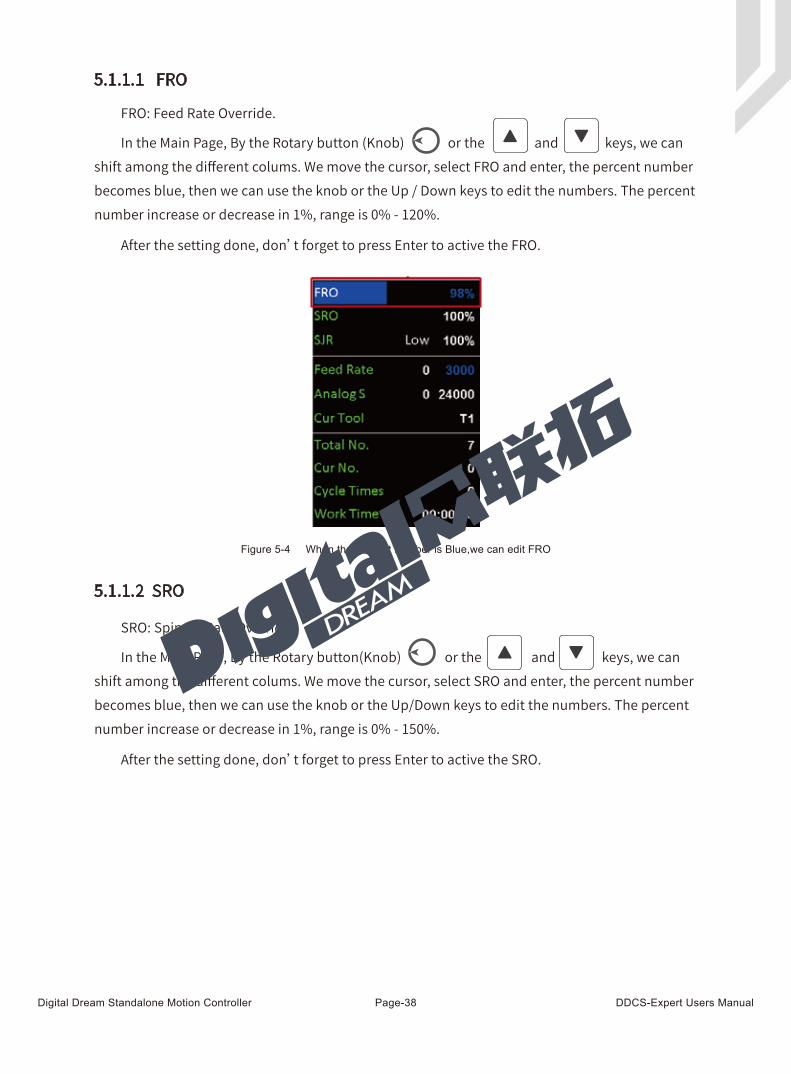
FRO: Feed Rate Override.
Figure 5-4 When the percent number is Blue,we can edit FRO
5.1.1.1 FRO
5.1.1.2 SRO
In the Main Page, By the Rotary button (Knob) or the and keys, we can shift among the different colums. We move the cursor, select FRO and enter, the percent number becomes blue, then we can use the knob or the Up / Down keys to edit the numbers. The percent number increase or decrease in 1%, range is 0% - 120%.
After the setting done, don’t forget to press Enter to active the FRO.
SRO: Spindle Rate Override
In the Main Page, By the Rotary button(Knob) or the and keys, we can shift among the different colums. We move the cursor, select SRO and enter, the percent number becomes blue, then we can use the knob or the Up/Down keys to edit the numbers. The percent number increase or decrease in 1%, range is 0% - 150%.
After the setting done, don’t forget to press Enter to active the SRO.
Digital Dream Standalone Motion Controller DDCS-Expert Users ManualPage-39
Figure 5-5 When the percent number is Blue,we can edit SRO
Figure 5-6 When the percent number is Blue,we can edit SJR
5.1.1.3 SJR/Jog Step
When the controller mode is CONT or MPG, it is “ SJR ”; When the controller mode is STEP,it is “ Jog Step ”.
When in the CONT or MPG mode, By the Rotary button(Knob) or the and
keys, we can shift among the different colums. We move the cursor, select SJR and enter, the
percent number becomes blue, then we can use the knob or the Up / Down keys to edit the
numbers. The percent number increase or decrease in 1%,range is 0% - 120%.
After the setting done, don’t forget to press Enter to active the SJR.
Digital Dream Standalone Motion Controller DDCS-Expert Users ManualPage-40
Figure 5-7 In Jog Step Mode Figure 5-8 Define Distance
Figure 5-9 Input Number Figure 5-20 new distance active
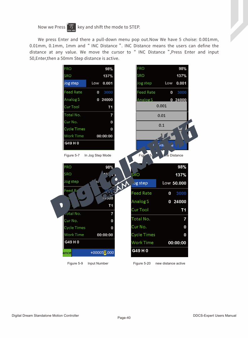
Now we Press key and shift the mode to STEP.
We press Enter and there a pull-down menu pop out.Now We have 5 choise: 0.001mm, 0.01mm, 0.1mm, 1mm and “ INC Distance ”. INC Distance means the users can define the distance at any value. We move the cursor to “ INC Distance ”,Press Enter and input 50,Enter,then a 50mm Step distance is active.
Digital Dream Standalone Motion Controller DDCS-Expert Users ManualPage-41
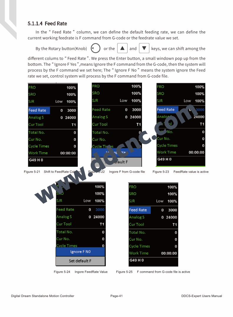
5.1.1.4 Feed Rate
Figure 5-21 Shift to FeedRate Column
Figure 5-24 Ingore FeedRate Value Figure 5-25 F command from G-code file is active
Figure 5-22 Ingore F from G-code file Figure 5-23 FeedRate value is active
By the Rotary button(Knob) or the and keys, we can shift among the
different colums to “ Feed Rate ”. We press the Enter button, a small windown pop up from the bottom. The “ Ignore F Yes ”,means Ignore the F command from the G-code, then the system will process by the F command we set here; The “ Ignore F No ” means the system ignore the Feed rate we set, control system will process by the F command from G-code file.
In the “ Feed Rate ” column, we can define the default feeding rate, we can define the current working feedrate is F command from G-code or the feedrate value we set.
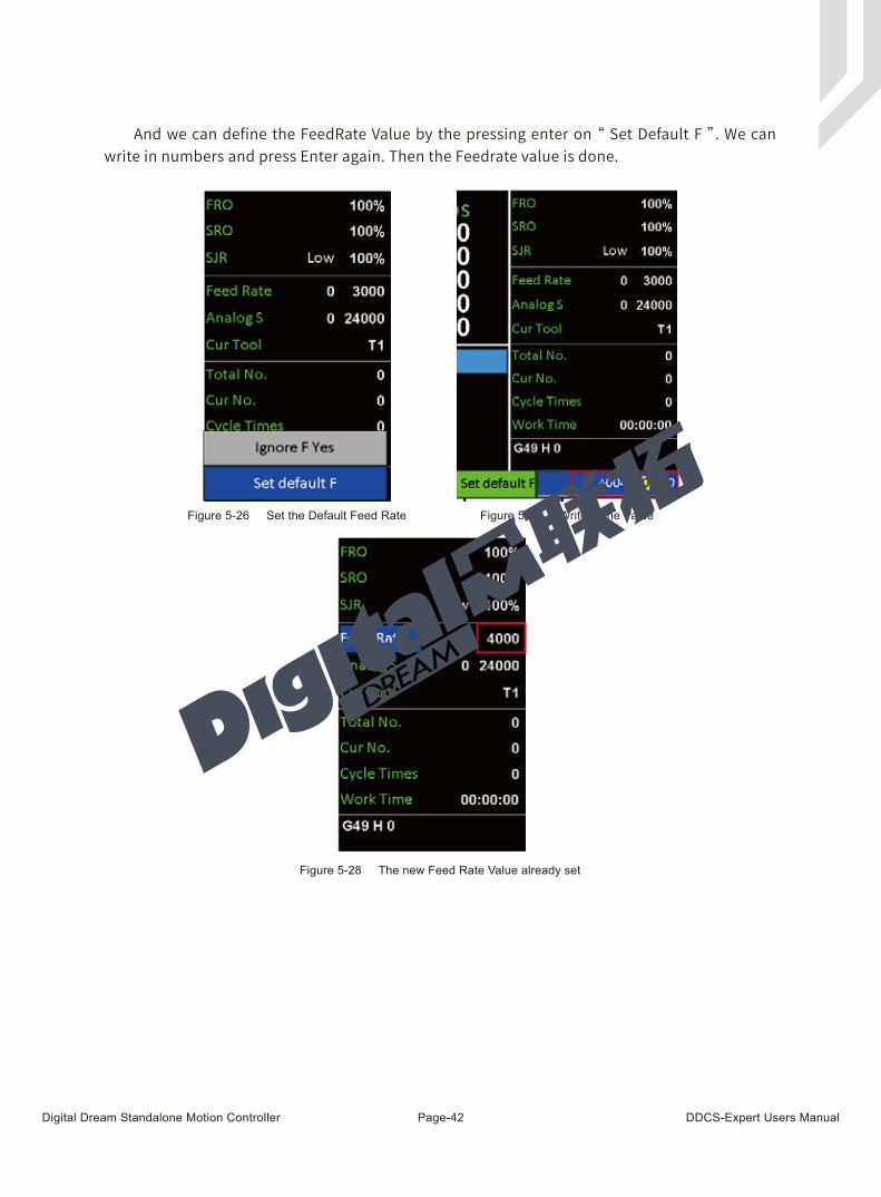
Digital Dream Standalone Motion Controller DDCS-Expert Users ManualPage-42
And we can define the FeedRate Value by the pressing enter on “ Set Default F ”. We can write in numbers and press Enter again. Then the Feedrate value is done.
Figure 5-26 Set the Default Feed Rate Figure 5-27 Write in the Value
Figure 5-28 The new Feed Rate Value already set

Digital Dream Standalone Motion Controller DDCS-Expert Users ManualPage-43
Figure 5-29 3 different spindle modes
Figure 5-30 Spindle in Analog Mode Figure 5-31 Spindle in Pul/Dir Mode Figure 5-32 Spindle in Multi-Speed Mode
5.1.1.5 Analog S/Servo S/Multi-SpeedBecause DDCS-Expert Controller has three kind Spindle Mode:
1) Analog: When the controller control the spindle speed by the anolog 0-10V voltage output;
2) Plu/Dir: When define the spindle mode as the Servo Spindle;
3) Multi-Speed ( Multi Spindle Speed ): When the controller control the spindle speed by 3 input ports, this is Multi spindle speed control.
Go to the Param Page and find the #79 parameter,press Enter,there are 3 options.Each option decide different spindle Mode:
Digital Dream Standalone Motion Controller DDCS-Expert Users ManualPage-44
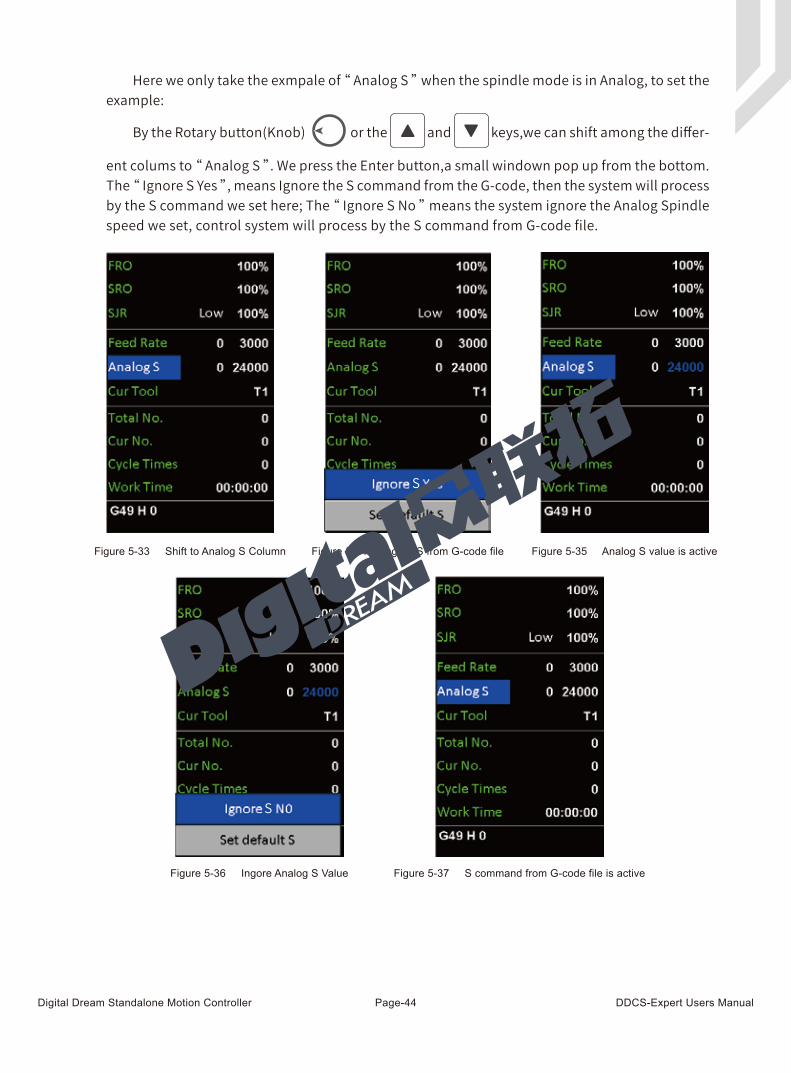
By the Rotary button(Knob) or the and keys,we can shift among the differ-
ent colums to “ Analog S ”. We press the Enter button,a small windown pop up from the bottom. The “ Ignore S Yes ”, means Ignore the S command from the G-code, then the system will process by the S command we set here; The “ Ignore S No ” means the system ignore the Analog Spindle speed we set, control system will process by the S command from G-code file.
Here we only take the exmpale of “ Analog S ” when the spindle mode is in Analog, to set the example:
Figure 5-33 Shift to Analog S Column Figure 5-34 Ingore S from G-code file Figure 5-35 Analog S value is active
S
Figure 5-36 Ingore Analog S Value Figure 5-37 S command from G-code file is active
S
Digital Dream Standalone Motion Controller DDCS-Expert Users ManualPage-45
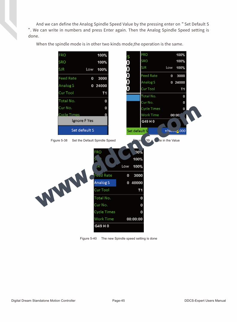
And we can define the Analog Spindle Speed Value by the pressing enter on “ Set Default S ”. We can write in numbers and press Enter again. Then the Analog Spindle Speed setting is done.
When the spindle mode is in other two kinds mode,the operation is the same.
Figure 5-38 Set the Default Spindle Speed Figure 5-39 Write in the Value
Figure 5-40 The new Spindle speed setting is done
Digital Dream Standalone Motion Controller DDCS-Expert Users ManualPage-46
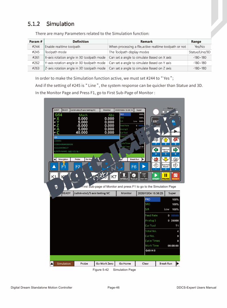
There are many Parameters related to the Simulation function:
In order to make the Simulation function active, we must set #244 to “ Yes ”;
And if the setting of #245 is “ Line ”, the system response can be quicker than Statue and 3D.
In the Monitor Page and Press F1, go to First Sub-Page of Monitor :
5.1.2 Simulation
Param # Definition Remark Range
Yes/No#244 Enable realtime toolpath When processing a file,active realtime toolpath or not
The Toolpath display modes
Can set a angle to simulate Based on X axis
Can set a angle to simulate Based on Y axis
Can set a angle to simulate Based on Z axis
Statue/Line/3D#245 Toolpath mode
-180~180#261 X-axis rotation angle in 3D toolpath mode
-180~180#262 Y-axis rotation angle in 3D toolpath mode
-180~180#263 Z-axis rotation angle in 3D toolpath mode
Figure 5-41 In the First Sub-page of Monitor and press F1 to go to the Simulation Page
Figure 5-42 Simulation Page
Digital Dream Standalone Motion Controller DDCS-Expert Users ManualPage-47
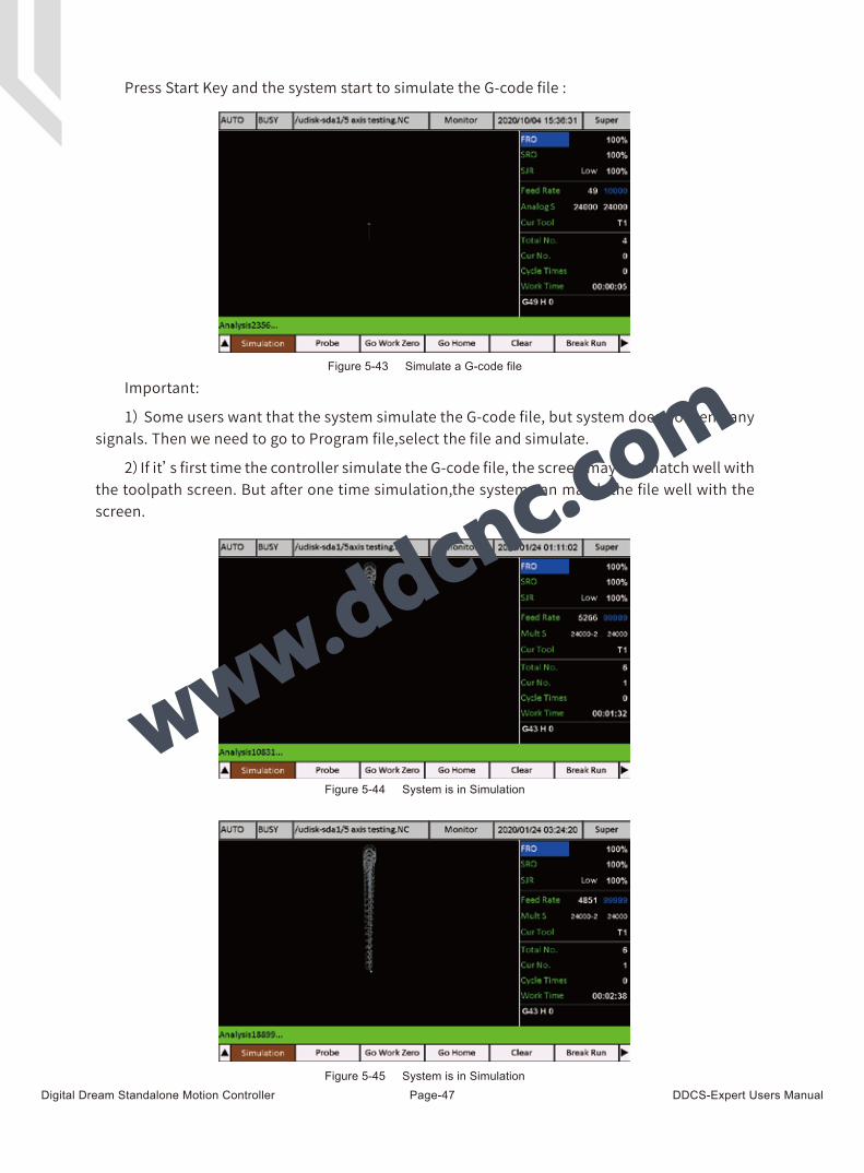
Press Start Key and the system start to simulate the G-code file :
Important:
1) Some users want that the system simulate the G-code file, but system does not send any signals. Then we need to go to Program file,select the file and simulate.
2)If it’s first time the controller simulate the G-code file, the screen may not match well with the toolpath screen. But after one time simulation,the system can match the file well with the screen.
Figure 5-43 Simulate a G-code file
Figure 5-44 System is in Simulation
Figure 5-45 System is in Simulation
Figure 1-15 DDCS-Expert start to simulate a G-code file
Digital Dream Standalone Motion Controller DDCS-Expert Users ManualPage-48
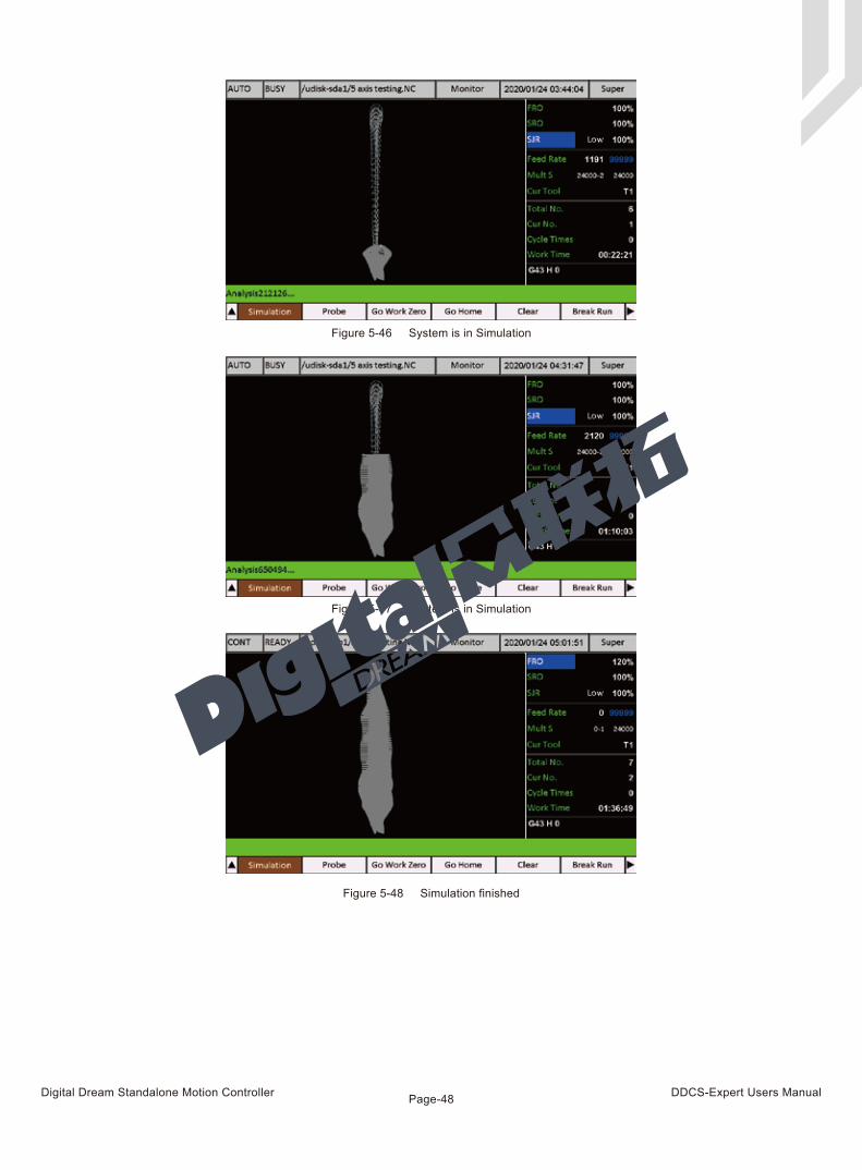
Figure 5-46 System is in Simulation
Figure 5-47 System is in Simulation
Figure 5-48 Simulation finished
Digital Dream Standalone Motion Controller DDCS-Expert Users ManualPage-49
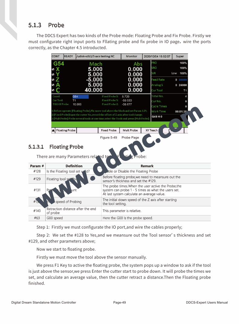
Figure 5-49 Probe Page
5.1.3 ProbeThe DDCS Expert has two kinds of the Probe mode: Floating Probe and Fix Probe. Firstly we
must configurate right input ports to Fllating probe and fix probe in IO page, wire the ports correctly, as the Chapter 4.5 introducted.
There are many Parameters related to the Floating Probe:
Step 1: Firstly we must configurate the IO port,and wire the cables properly;
Step 2: We set the #128 to Yes,and we meansure out the Tool sensor’s thickness and set #129, and other parameters above;
Now we start to floating probe.
Firstly we must move the tool above the sensor manually.
We press F1 Key to active the floating probe, the system pops up a window to ask if the tool is just above the sensor,we press Enter the cutter start to probe down. It will probe the times we set, and calculate an average value, then the cutter retract a distance.Then the Floating probe finished.
5.1.3.1 Floating Probe
Param # Definition Remark
#129 Floating tool set thickness
Is the Floating tool set valid?#128
Before floating probe,we need to meansure out the sensor ’s thickness and set the #129.
Enable or Disable the Floating Probe
The probe times.When the user active the Probe,thesystem can probe 1 - 5 times as what the users set.At last system calculate an average value.
#131 Probing cycle count
The initial down speed of the Z axis after starting the tool setting.#132 Initial speed of Probing
This parameter is relative.#140 Retraction distance after the endof probe
Here the G00 is the probe speed.#63 G00 speed
Digital Dream Standalone Motion Controller DDCS-Expert Users ManualPage-50
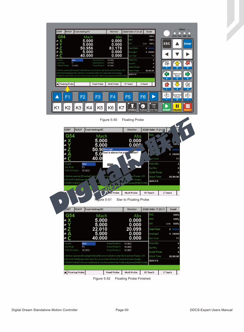
Figure 5-50 Floating Probe
Figure 5-51 Star to Floating Probe
Figure 5-52 Floating Probe Finished
Digital Dream Standalone Motion Controller DDCS-Expert Users ManualPage-51
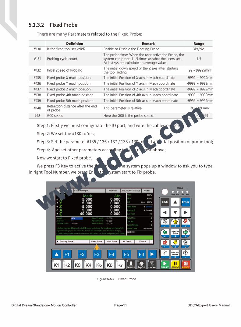
Figure 5-53 Fixed Probe
Param #
1-5
#130
#131
#132
#135
#136
#137
#138
#139
#140
#63 G00 speed
There are many Parameters related to the Fixed Probe:
Step 1: Firstly we must configurate the IO port, and wire the cables properly;
Step 2: We set the #130 to Yes;
Step 3: Set the parameter #135 / 136 / 137 / 138 / 139 to find an inital position of probe tool;
Step 4: And set other parameters according to your request above;
Now we start to Fixed probe.
We press F3 Key to active the fixed probe, the system pops up a window to ask you to type in right Tool Number, we press Enter,the system start to Fix probe.
5.1.3.2 Fixed Probe
Definition Remark Range
Yes/NoIs the fixed tool set valid? Enable or Disable the Floating Probe
The probe times.When the user active the Probe, thesystem can probe 1 - 5 times as what the users set.At last system calculate an average value.
Probing cycle count
99 - 99999mmThe initial down speed of the Z axis after starting the tool setting.Initial speed of Probing
-9999 ~ 9999mmThe initial Position of X axis in Mach coordinateFixed probe X mach position
-9999 ~ 9999mmThe initial Position of Y axis in Mach coordinateFixed probe Y mach position
-9999 ~ 9999mmThe initial Position of Z axis in Mach coordinateFixed probe Z mach position
-9999 ~ 9999mmThe initial Position of 4th axis in Mach coordinateFixed probe 4th mach position
-9999 ~ 9999mmThe initial Position of 5th axis in Mach coordinateFixed probe 5th mach position
0 - 999 mmThis parameter is relative.Retraction distance after the endof probe
99 - 99999Here the G00 is the probe speed.
Digital Dream Standalone Motion Controller DDCS-Expert Users ManualPage-52
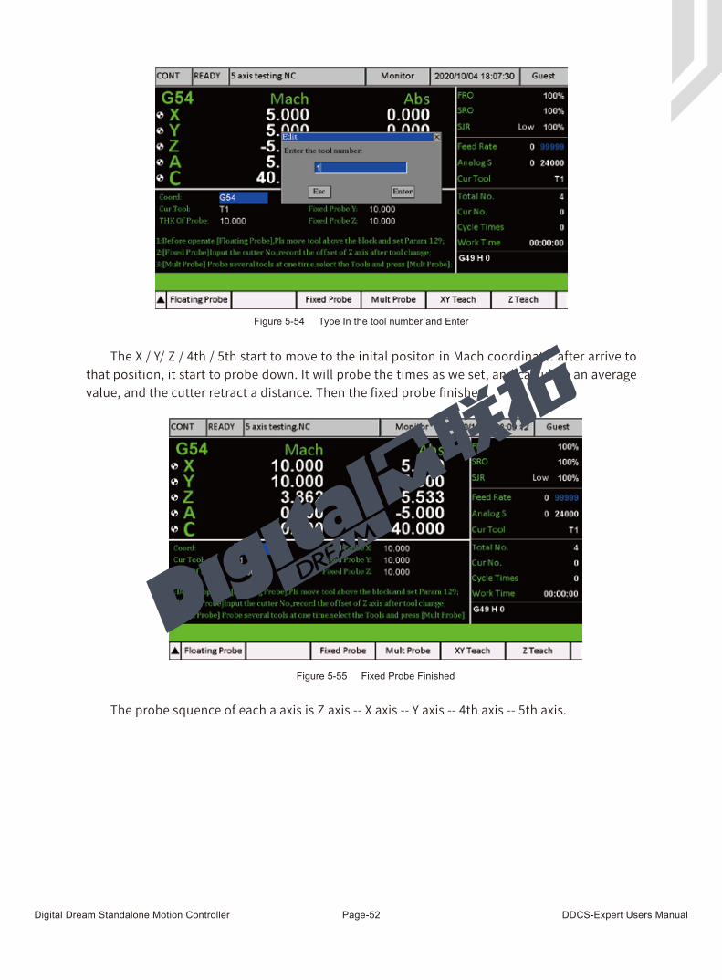
The X / Y/ Z / 4th / 5th start to move to the inital positon in Mach coordinate. after arrive to that position, it start to probe down. It will probe the times as we set, and calculate an average value, and the cutter retract a distance. Then the fixed probe finished.
The probe squence of each a axis is Z axis -- X axis -- Y axis -- 4th axis -- 5th axis.
Figure 5-54 Type In the tool number and Enter
Figure 5-55 Fixed Probe Finished
Digital Dream Standalone Motion Controller DDCS-Expert Users ManualPage-53
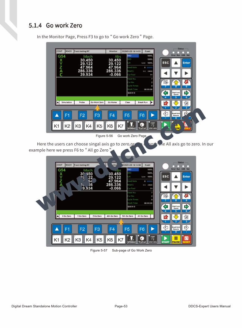
In the Monitor Page, Press F3 to go to “ Go work Zero ” Page.
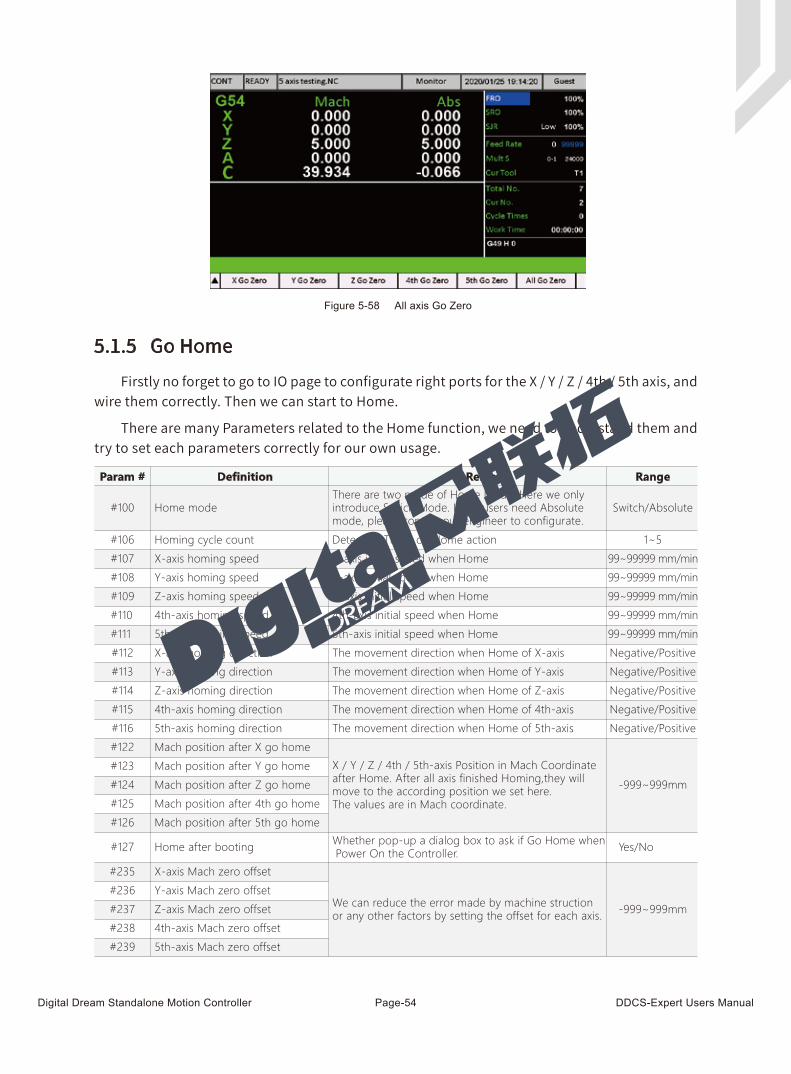
Here the users can choose singal axis go to zero,or can choose the All axis go to zero. In our example here we press F6 to “ All go Zero ”.
Figure 5-57 Sub-page of Go Work Zero
5.1.4 Go work Zero
Figure 5-56 Go work Zero Page
Digital Dream Standalone Motion Controller DDCS-Expert Users ManualPage-54
Firstly no forget to go to IO page to configurate right ports for the X / Y / Z / 4th / 5th axis, and wire them correctly. Then we can start to Home.
There are many Parameters related to the Home function, we need to understand them and try to set each parameters correctly for our own usage.
Figure 5-58 All axis Go Zero
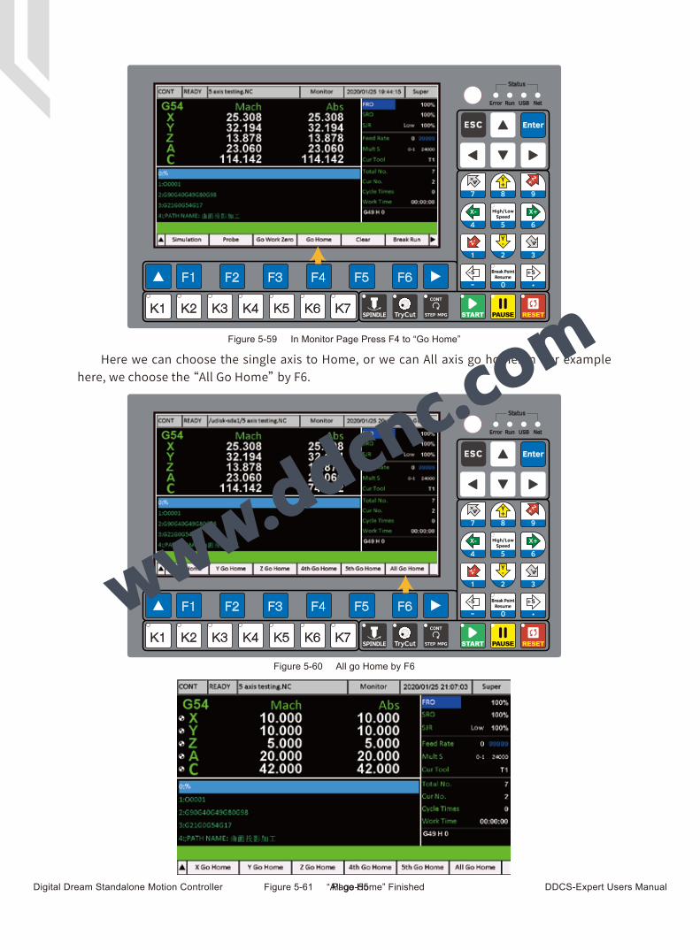
5.1.5 Go Home
Param # Definition Remark Range
There are two mode of Home Mode, Here we only introduce Swtich Mode. If the users need Absolute mode, please contact our engineer to configurate.
#100
#106
#107
#112
#113
#114
#115
#116
#122
#123
#124
#125
#126
#127
#235
#236
#237
#238
#239
Home mode Switch/Absolute
-999~999mm
Homing cycle count 1~5Detection Times of Home action
X-axis homing speed 99~99999 mm/minX-axis initial speed when Home
#108 Y-axis homing speed 99~99999 mm/minY-axis initial speed when Home
#109 Z-axis homing speed 99~99999 mm/minZ-axis initial speed when Home
#110 4th-axis homing speed 99~99999 mm/min4th-axis initial speed when Home
#111 5th-axis homing speed 99~99999 mm/min5th-axis initial speed when Home
The movement direction when Home of X-axis
The movement direction when Home of Y-axis
The movement direction when Home of Z-axis
The movement direction when Home of 4th-axis
The movement direction when Home of 5th-axis
X / Y / Z / 4th / 5th-axis Position in Mach Coordinate after Home. After all axis finished Homing,they will move to the according position we set here. The values are in Mach coordinate.
Yes/NoWhether pop-up a dialog box to ask if Go Home when Power On the Controller.
X-axis homing direction Negative/Positive
Negative/Positive
Negative/Positive
Negative/Positive
Negative/Positive
Y-axis homing direction
Z-axis homing direction
4th-axis homing direction
5th-axis homing direction
Mach position after X go home
Mach position after Y go home
Mach position after Z go home
Mach position after 4th go home
-999~999mm
Mach position after 5th go home
Home after booting
X-axis Mach zero offset
We can reduce the error made by machine structionor any other factors by setting the offset for each axis.
Y-axis Mach zero offset
Z-axis Mach zero offset
4th-axis Mach zero offset
5th-axis Mach zero offset
Digital Dream Standalone Motion Controller DDCS-Expert Users ManualPage-55
Here we can choose the single axis to Home, or we can All axis go home. In our example here, we choose the “All Go Home” by F6.
Figure 5-59 In Monitor Page Press F4 to “Go Home”
Figure 5-60 All go Home by F6
Figure 5-61 “All go Home” Finished
Digital Dream Standalone Motion Controller DDCS-Expert Users ManualPage-56
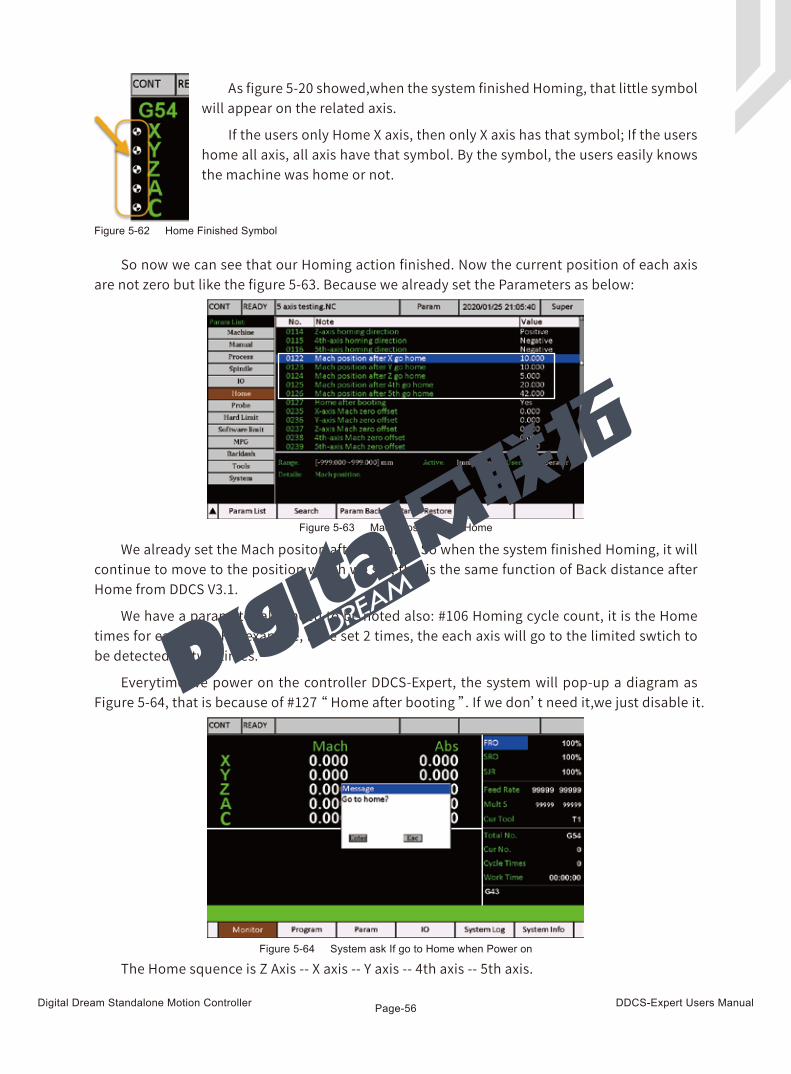
So now we can see that our Homing action finished. Now the current position of each axis are not zero but like the figure 5-63. Because we already set the Parameters as below:
We already set the Mach positon after Homing. So when the system finished Homing, it will continue to move to the position which we set, this is the same function of Back distance after Home from DDCS V3.1.
We have a parameter also need to be noted also: #106 Homing cycle count, it is the Home times for each axis. For example, if we set 2 times, the each axis will go to the limited swtich to be detected by two times.
Everytime we power on the controller DDCS-Expert, the system will pop-up a diagram as Figure 5-64, that is because of #127 “ Home after booting ”. If we don’t need it,we just disable it.
The Home squence is Z Axis -- X axis -- Y axis -- 4th axis -- 5th axis.
As figure 5-20 showed,when the system finished Homing, that little symbol will appear on the related axis.
If the users only Home X axis, then only X axis has that symbol; If the users home all axis, all axis have that symbol. By the symbol, the users easily knows the machine was home or not.
Figure 5-62 Home Finished Symbol
Figure 5-63 Mach Postion after Home
Figure 5-64 System ask If go to Home when Power on
Digital Dream Standalone Motion Controller DDCS-Expert Users ManualPage-57
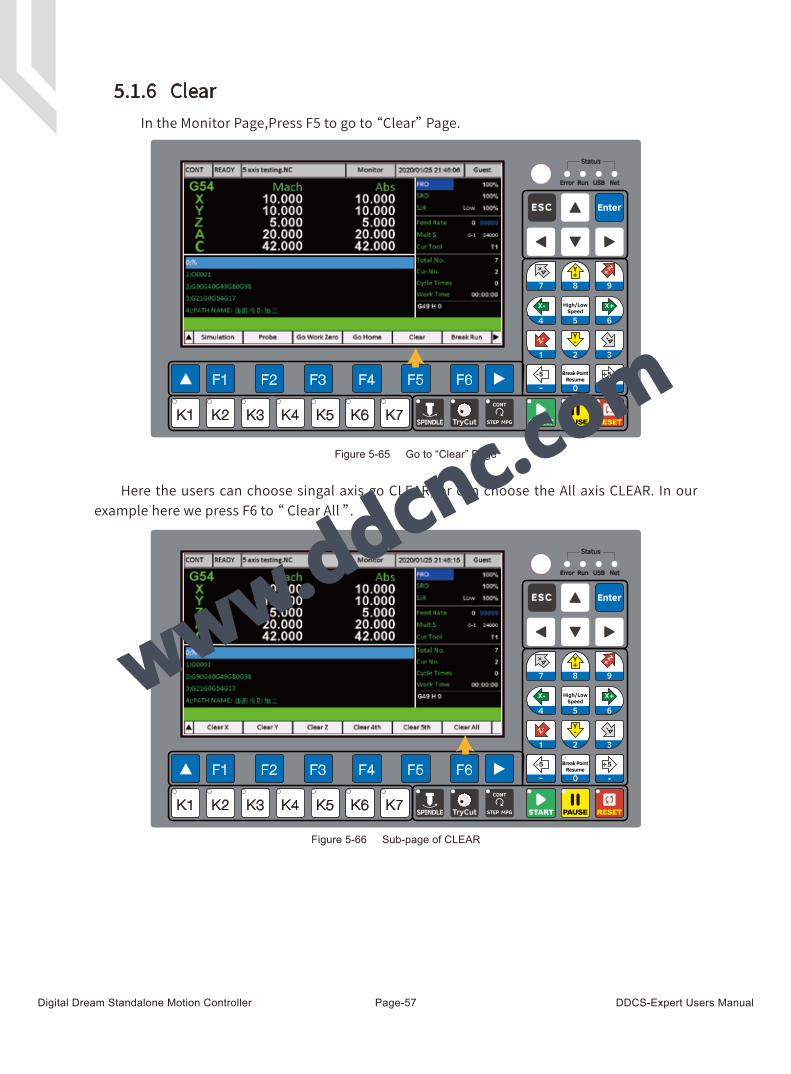
In the Monitor Page,Press F5 to go to “Clear” Page.
Here the users can choose singal axis go CLEAR, or can choose the All axis CLEAR. In our example here we press F6 to “ Clear All ”.
Figure 5-65 Go to “Clear” Page
Figure 5-66 Sub-page of CLEAR
5.1.6 Clear
Digital Dream Standalone Motion Controller DDCS-Expert Users ManualPage-58
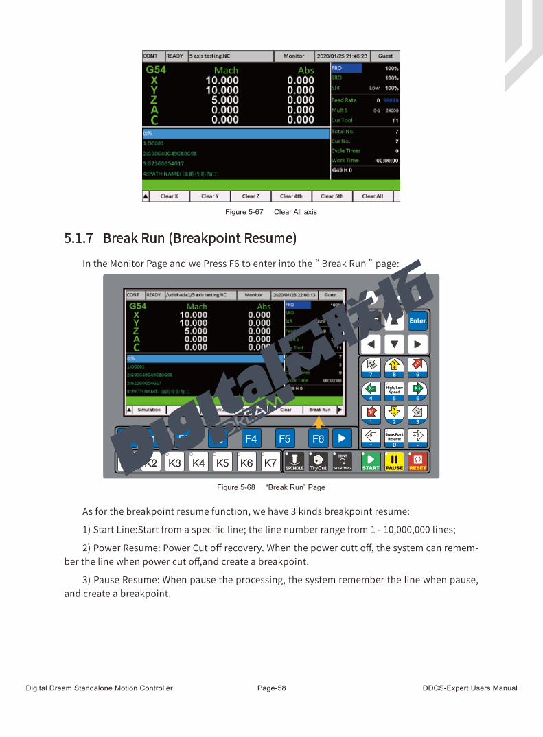
As for the breakpoint resume function, we have 3 kinds breakpoint resume:
1) Start Line:Start from a specific line; the line number range from 1 - 10,000,000 lines;
2) Power Resume: Power Cut off recovery. When the power cutt off, the system can remem-ber the line when power cut off,and create a breakpoint.
3) Pause Resume: When pause the processing, the system remember the line when pause, and create a breakpoint.
In the Monitor Page and we Press F6 to enter into the “ Break Run ” page:
Figure 5-67 Clear All axis
Figure 5-68 “Break Run” Page
5.1.7 Break Run (Breakpoint Resume)
Digital Dream Standalone Motion Controller DDCS-Expert Users ManualPage-59
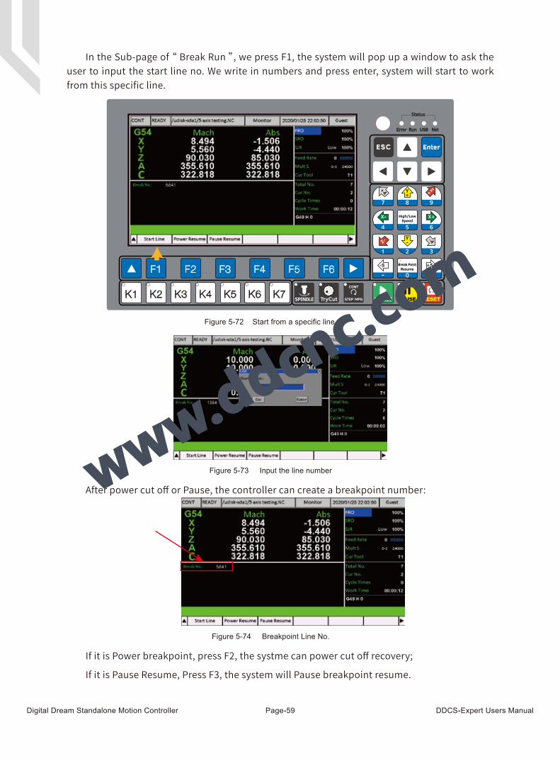
In the Sub-page of “ Break Run ”, we press F1, the system will pop up a window to ask the user to input the start line no. We write in numbers and press enter, system will start to work from this specific line.
After power cut off or Pause, the controller can create a breakpoint number:
If it is Power breakpoint, press F2, the systme can power cut off recovery;
If it is Pause Resume, Press F3, the system will Pause breakpoint resume.
Figure 5-72 Start from a specific line
Figure 5-73 Input the line number
Figure 5-74 Breakpoint Line No.
Digital Dream Standalone Motion Controller DDCS-Expert Users ManualPage-60
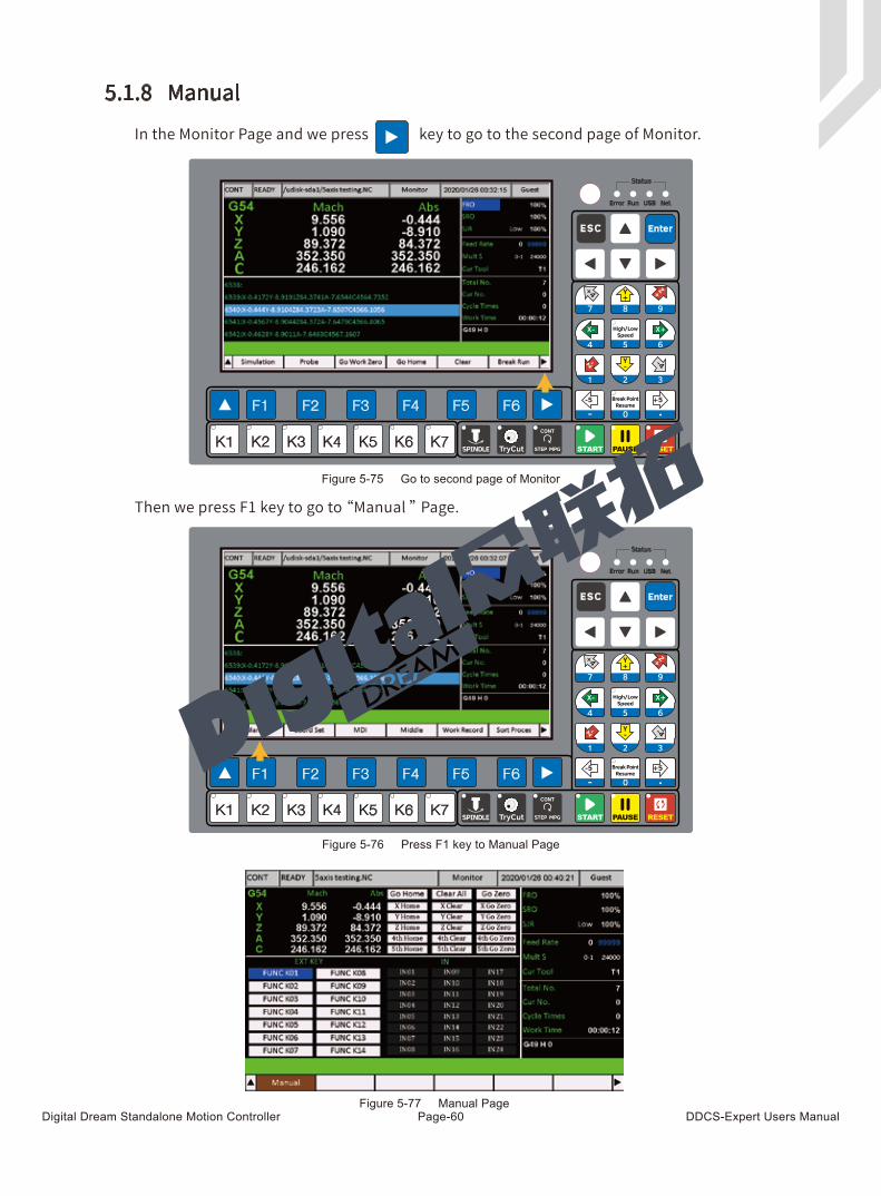
Figure 5-75 Go to second page of Monitor
Figure 5-76 Press F1 key to Manual Page
Figure 5-77 Manual Page
5.1.8 Manual
In the Monitor Page and we press key to go to the second page of Monitor.
Then we press F1 key to go to “Manual ” Page.
Digital Dream Standalone Motion Controller DDCS-Expert Users ManualPage-61
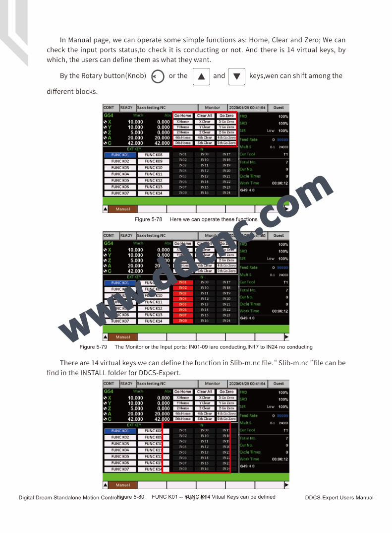
Figure 5-78 Here we can operate these functions
There are 14 virtual keys we can define the function in Slib-m.nc file.“ Slib-m.nc ”file can be find in the INSTALL folder for DDCS-Expert.
In Manual page, we can operate some simple functions as: Home, Clear and Zero; We can check the input ports status,to check it is conducting or not. And there is 14 virtual keys, by which, the users can define them as what they want.
By the Rotary button(Knob) or the and keys,wen can shift among the
different blocks.
Figure 5-79 The Monitor or the Input ports: IN01-09 iare conducting,IN17 to IN24 no conducting
Figure 5-80 FUNC K01 -- FUNC K14 Vitual Keys can be defined

Digital Dream Standalone Motion Controller DDCS-Expert Users ManualPage-62
5.1.9 Coord Set
Then we press F2 key to go to “ Coord Set ” Page. In the Coord Set Page, we can Select coor-dinate, and also we can edit the offset between the G54 / G55 / G56 / G57 / G58 / G59 and Mach-anical Coordinate.
In the first Page, there is functions as:Select Coord / Clear X / Clear Z / Z Step / Deeper:
We Press the Key to go to the second page of Coord Set:
Figure 5-81 Press F1 key to “Coord Set” Page
Figure 5-82 First Page of Coord Set
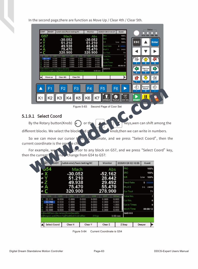
Digital Dream Standalone Motion Controller DDCS-Expert Users ManualPage-63
5.1.9.1 Select Coord
In the second page,there are function as Move Up / Clear 4th / Clear 5th.
So we can move our cursor to any Coordinate, and we press “Select Coord”, then the current coordinate is the one we choose.
For example, we move the cursor to any block on G57, and we press “Select Coord” key, then the current Coordinate change from G54 to G57:
Figure 5-84 Current Coordinate is G54
Figure 5-83 Second Page of Coor Set
By the Rotary button(Knob) or the and keys,wen can shift among the
different blocks. We select the block,and press Enter or knob,then we can write in numbers.
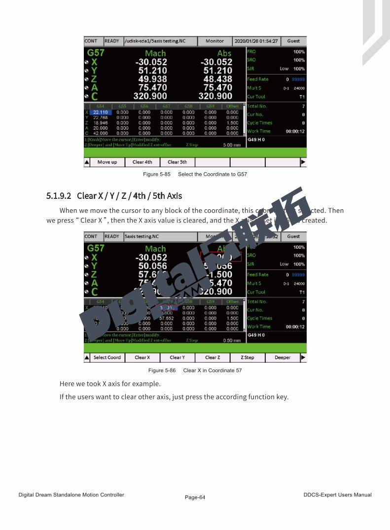
Digital Dream Standalone Motion Controller DDCS-Expert Users ManualPage-64
5.1.9.2 Clear X / Y / Z / 4th / 5th AxisWhen we move the cursor to any block of the coordinate, this coordinate is selected. Then
we press “ Clear X ”, then the X axis value is cleared, and the X axis offset in G57 is created.
Here we took X axis for example.
If the users want to clear other axis, just press the according function key.
Figure 5-85 Select the Coordinate to G57
Figure 5-86 Clear X in Coordinate 57
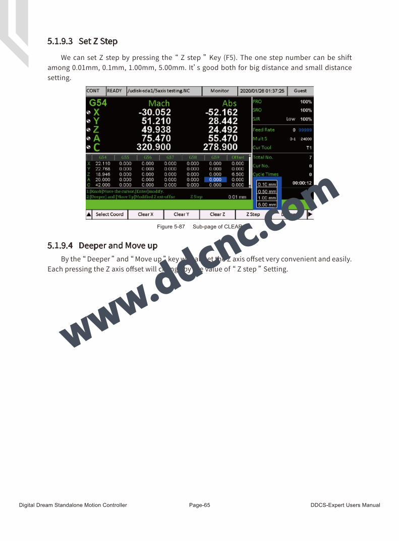
Digital Dream Standalone Motion Controller DDCS-Expert Users ManualPage-65
Figure 5-87 Sub-page of CLEAR
5.1.9.3 Set Z Step
5.1.9.4 Deeper and Move up
We can set Z step by pressing the “ Z step ” Key (F5). The one step number can be shift among 0.01mm, 0.1mm, 1.00mm, 5.00mm. It’s good both for big distance and small distance setting.
By the “ Deeper ” and “ Move up ” key we can set the Z axis offset very convenient and easily. Each pressing the Z axis offset will change by the value of “ Z step ” Setting.
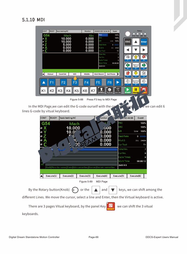
Digital Dream Standalone Motion Controller DDCS-Expert Users ManualPage-66
In the MDI Page,we can edit the G-code ourself with the controller panel. Here we can edit 6 lines G-code by vitual keyboard.
Figure 5-89 MDI Page
5.1.10 MDI
Figure 5-88 Press F3 key to MDI Page
By the Rotary button(Knob) or the and keys, we can shift among the
different Lines. We move the cursor, select a line and Enter, then the Virtual keyboard is active.
There are 3 pages Vitual keyboard, by the panel Key we can shift the 3 vitual
keyboards.
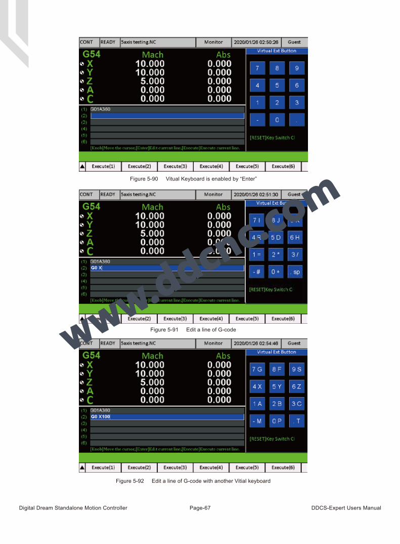
Digital Dream Standalone Motion Controller DDCS-Expert Users ManualPage-67
Figure 5-90 Vitual Keyboard is enabled by “Enter”
Figure 5-91 Edit a line of G-code
Figure 5-92 Edit a line of G-code with another Vitial keyboard
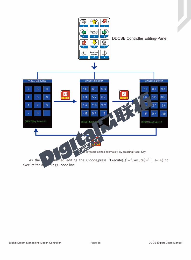
Digital Dream Standalone Motion Controller DDCS-Expert Users ManualPage-68
As the users finished editing the G-code,press “Execute(1)”--“Execute(6)” (F1--F6) to execute the according G-code line.
Figure 5-93 The 3 pages vitual keyboard shifted alternately by pressing Reset Key
DDCSE Controller Editing-Panel
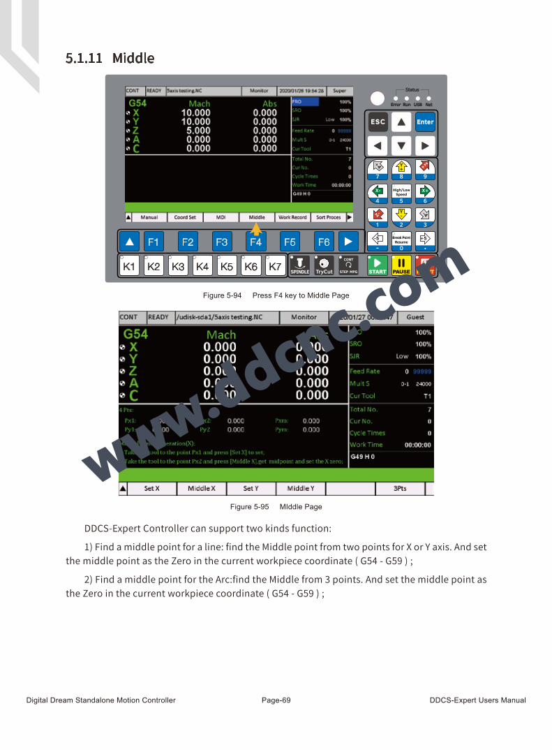
Digital Dream Standalone Motion Controller DDCS-Expert Users ManualPage-69
DDCS-Expert Controller can support two kinds function:
1) Find a middle point for a line: find the Middle point from two points for X or Y axis. And set the middle point as the Zero in the current workpiece coordinate ( G54 - G59 ) ;
2) Find a middle point for the Arc:find the Middle from 3 points. And set the middle point as the Zero in the current workpiece coordinate ( G54 - G59 ) ;
5.1.11 Middle
Figure 5-94 Press F4 key to Middle Page
Figure 5-95 MIddle Page
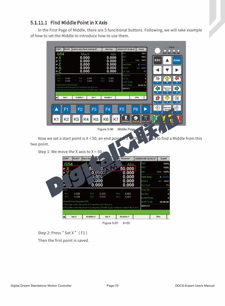
Digital Dream Standalone Motion Controller DDCS-Expert Users ManualPage-70
5.1.11.1 Find Middle Point in X AxisIn the First Page of Middle, there are 5 funcitional buttons. Following, we will take example
of how to set the Middle to introduce how to use them.
Now we set a start point is X = 50, an end point is X = 100. We need to find a Middle from this two point.
Step 1: We move the X axis to X = 50 :
Step 2: Press “ Set X ” ( F1 )
Then the first point is saved.
Figure 5-96 Middle Page
Figure 5-97 X=50
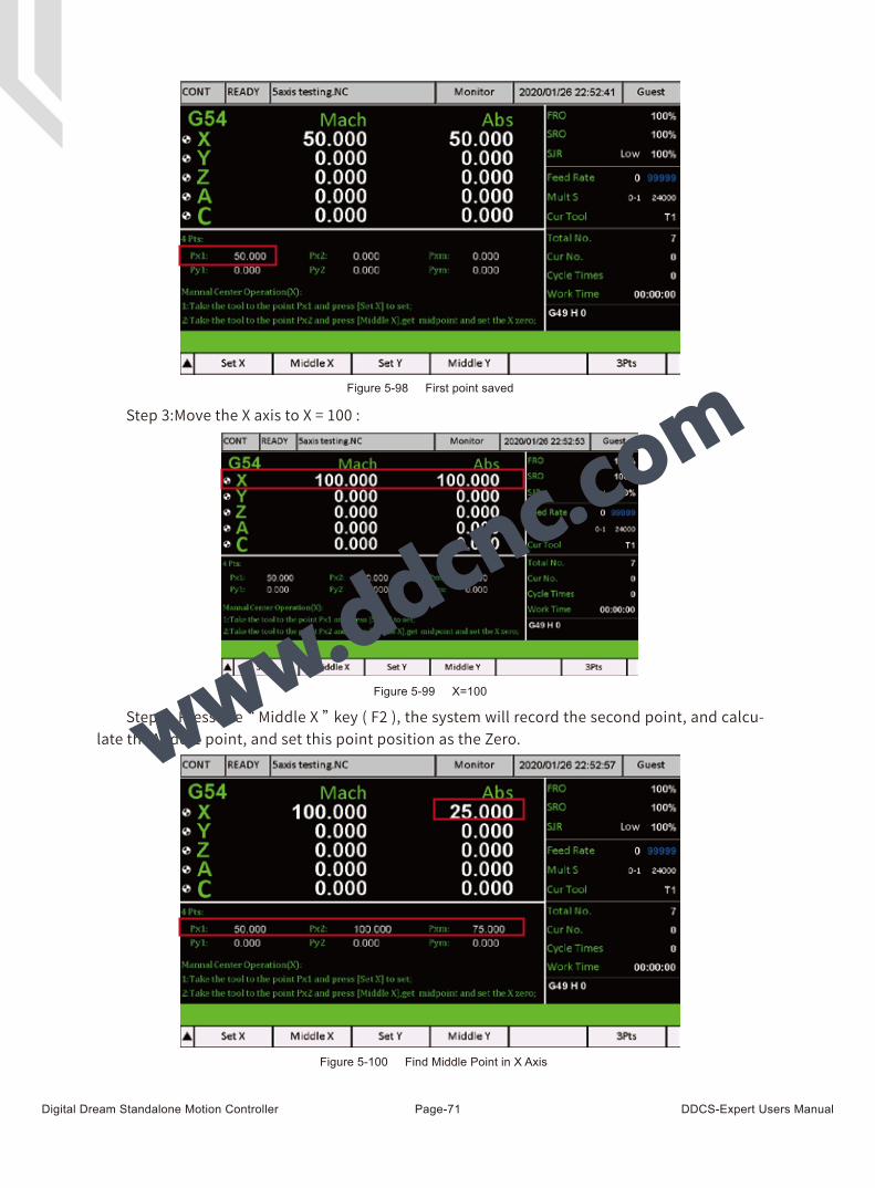
Digital Dream Standalone Motion Controller DDCS-Expert Users ManualPage-71
Step 3:Move the X axis to X = 100 :
Step 4: Press the “ Middle X ” key ( F2 ), the system will record the second point, and calcu-late the Middle point, and set this point position as the Zero.
Figure 5-99 X=100
Figure 5-100 Find Middle Point in X Axis
Figure 5-98 First point saved
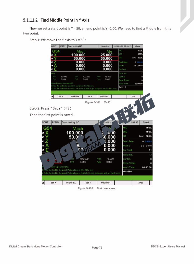
Digital Dream Standalone Motion Controller DDCS-Expert Users ManualPage-72
5.1.11.2 Find Middle Point in Y Axis
Now we set a start point is Y = 50, an end point is Y =1 00. We need to find a Middle from this two point.
Step 1: We move the Y axis to Y = 50 :
Step 2: Press “ Set Y ” ( F3 )
Then the first point is saved.
Figure 5-101 X=50
Figure 5-102 First point saved
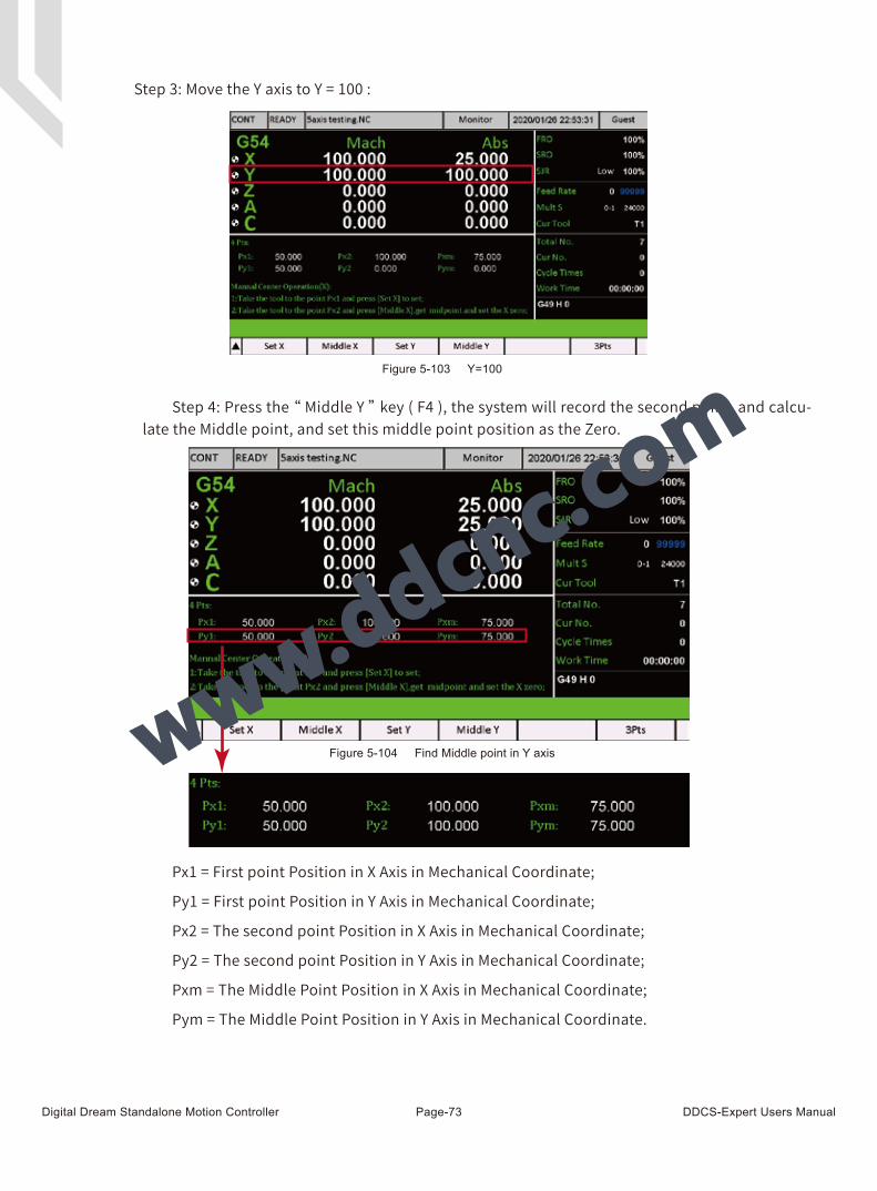
Digital Dream Standalone Motion Controller DDCS-Expert Users ManualPage-73
Step 3: Move the Y axis to Y = 100 :
Step 4: Press the “ Middle Y ” key ( F4 ), the system will record the second point, and calcu-late the Middle point, and set this middle point position as the Zero.
Px1 = First point Position in X Axis in Mechanical Coordinate;
Py1 = First point Position in Y Axis in Mechanical Coordinate;
Px2 = The second point Position in X Axis in Mechanical Coordinate;
Py2 = The second point Position in Y Axis in Mechanical Coordinate;
Pxm = The Middle Point Position in X Axis in Mechanical Coordinate;
Pym = The Middle Point Position in Y Axis in Mechanical Coordinate.
Figure 5-103 Y=100
Figure 5-104 Find Middle point in Y axis
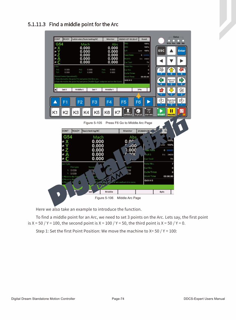
Digital Dream Standalone Motion Controller DDCS-Expert Users ManualPage-74
5.1.11.3 Find a middle point for the Arc
Here we also take an example to introduce the function.
To find a middle point for an Arc, we need to set 3 points on the Arc. Lets say, the first point is X = 50 / Y = 100, the second point is X = 100 / Y = 50, the third point is X = 50 / Y = 0.
Step 1: Set the first Point Position: We move the machine to X= 50 / Y = 100:
Figure 5-105 Press F6 Go to MIddle Arc Page
Figure 5-106 MIddle Arc Page
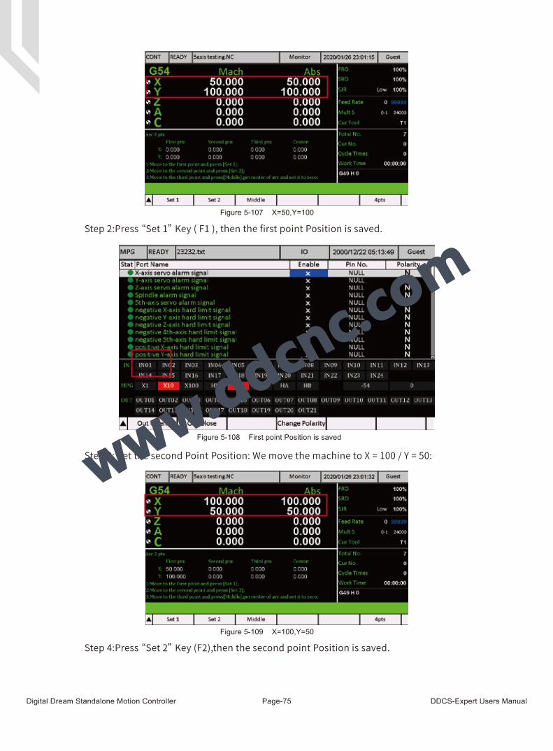
Digital Dream Standalone Motion Controller DDCS-Expert Users ManualPage-75
Step 3: Set the second Point Position: We move the machine to X = 100 / Y = 50:
Figure 5-107 X=50,Y=100
Figure 5-108 First point Position is saved
Figure 5-109 X=100,Y=50
Step 2:Press “Set 1” Key ( F1 ), then the first point Position is saved.
Step 4:Press “Set 2” Key (F2),then the second point Position is saved.
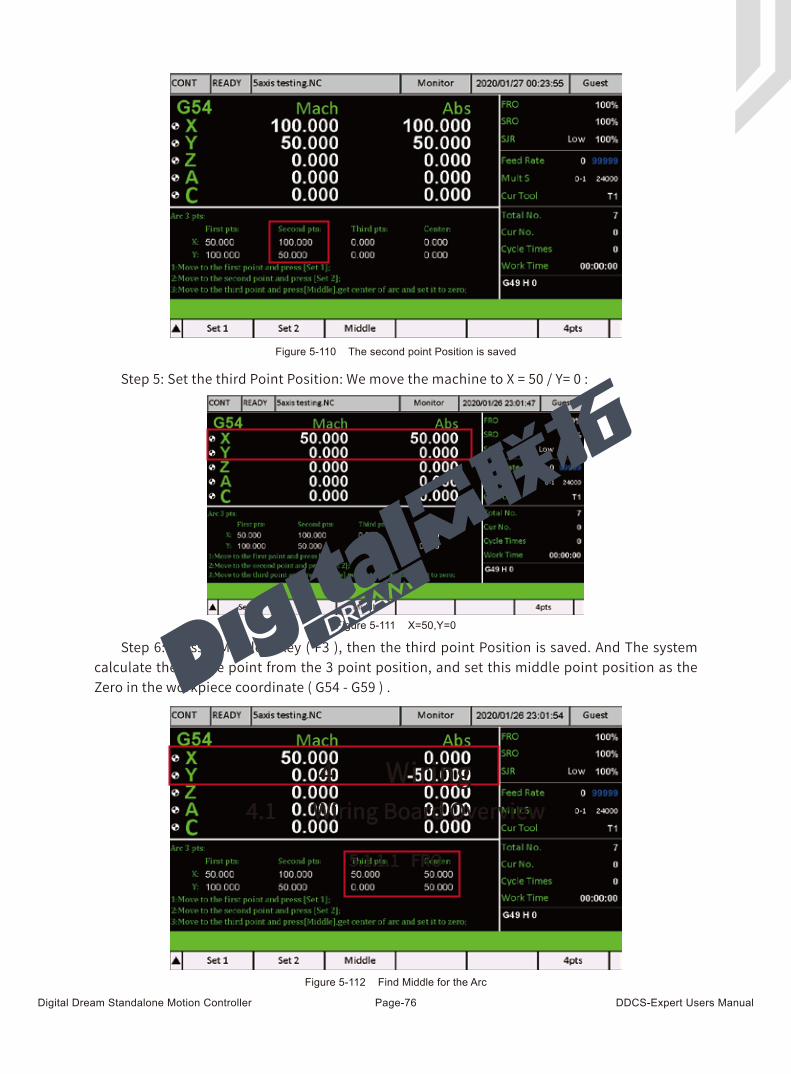
Digital Dream Standalone Motion Controller DDCS-Expert Users ManualPage-76
Step 5: Set the third Point Position: We move the machine to X = 50 / Y= 0 :
Figure 5-110 The second point Position is saved
Figure 5-112 Find Middle for the Arc
Figure 5-111 X=50,Y=0
Step 6: Press “ Middle ” Key ( F3 ), then the third point Position is saved. And The system calculate the Middle point from the 3 point position, and set this middle point position as the Zero in the workpiece coordinate ( G54 - G59 ) .
4 Wiring4.1 Wiring Board Overview
5.1.1.1 FRO
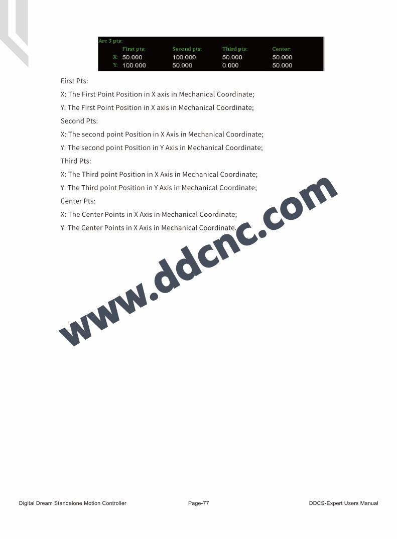
Digital Dream Standalone Motion Controller DDCS-Expert Users ManualPage-77
First Pts:
X: The First Point Position in X axis in Mechanical Coordinate;
Y: The First Point Position in X axis in Mechanical Coordinate;
Second Pts:
X: The second point Position in X Axis in Mechanical Coordinate;
Y: The second point Position in Y Axis in Mechanical Coordinate;
Third Pts:
X: The Third point Position in X Axis in Mechanical Coordinate;
Y: The Third point Position in Y Axis in Mechanical Coordinate;
Center Pts:
X: The Center Points in X Axis in Mechanical Coordinate;
Y: The Center Points in X Axis in Mechanical Coordinate.
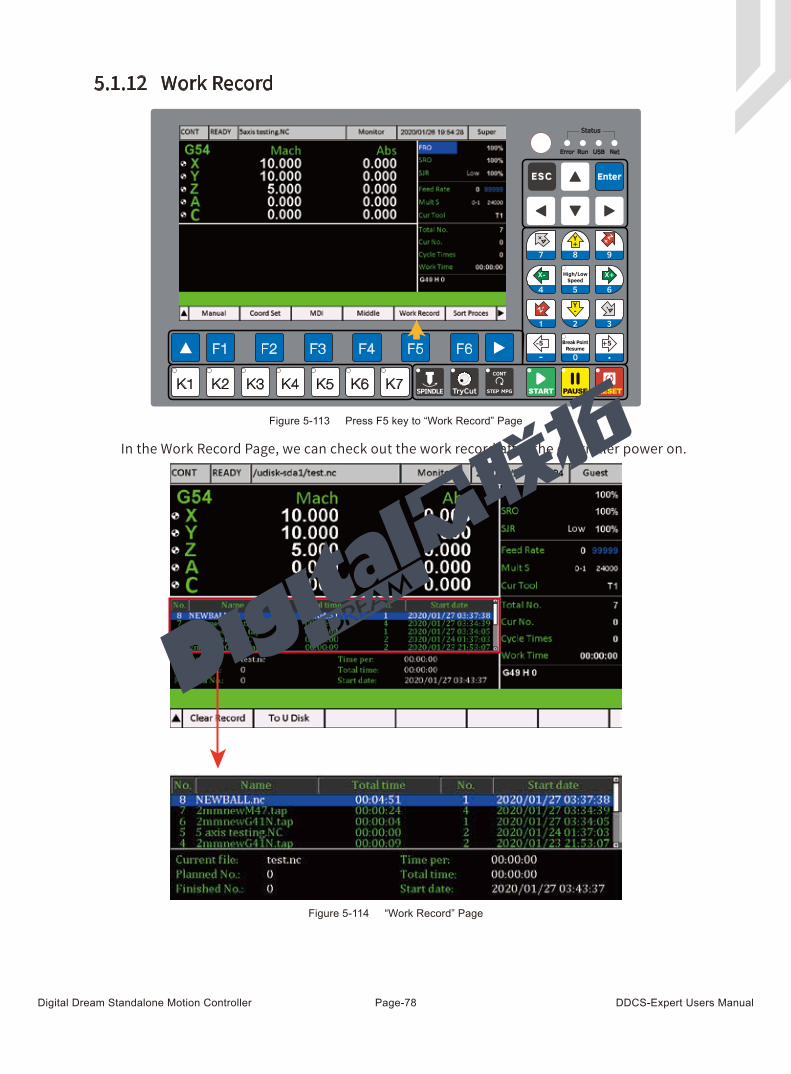
Digital Dream Standalone Motion Controller DDCS-Expert Users ManualPage-78
In the Work Record Page, we can check out the work record after the controller power on.
5.1.12 Work Record
Figure 5-113 Press F5 key to “Work Record” Page
Figure 5-114 “Work Record” Page
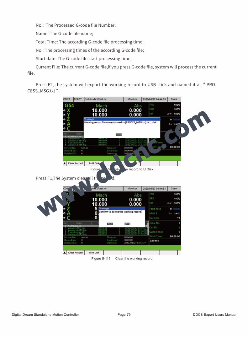
Digital Dream Standalone Motion Controller DDCS-Expert Users ManualPage-79
Press F2, the system will export the working record to USB stick and named it as “ PRO-CESS_MSG.txt ”.
Press F1,The System clear all the record.
No.: The Processed G-code file Number;
Name: The G-code file name;
Total Time: The according G-code file processing time;
No.: The processing times of the according G-code file;
Start date: The G-code file start processing time;
Current File: The current G-code file,if you press G-code file, system will process the current file.
Figure 5-115 Save the record to U Disk
Figure 5-116 Clear the working record
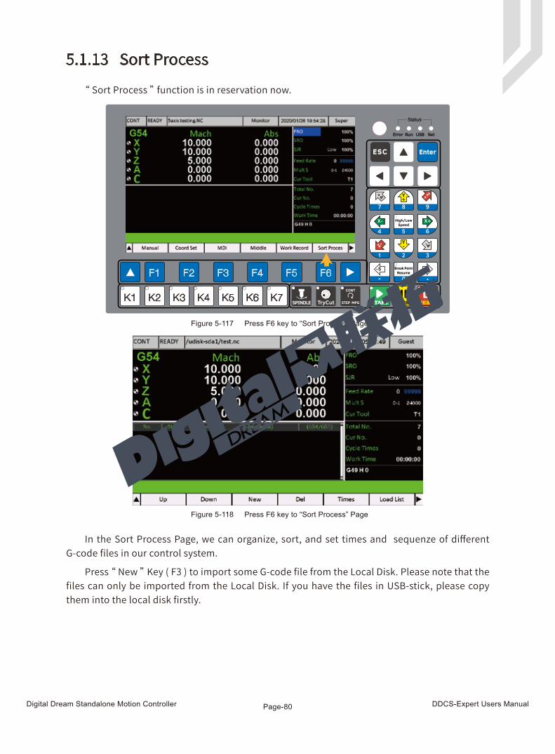
Digital Dream Standalone Motion Controller DDCS-Expert Users ManualPage-80
5.1.13 Sort Process
In the Sort Process Page, we can organize, sort, and set times and sequenze of different G-code files in our control system.
Press “ New ” Key ( F3 ) to import some G-code file from the Local Disk. Please note that the files can only be imported from the Local Disk. If you have the files in USB-stick, please copy them into the local disk firstly.
“ Sort Process ” function is in reservation now.
Figure 5-117 Press F6 key to “Sort Process” Page
Figure 5-118 Press F6 key to “Sort Process” Page
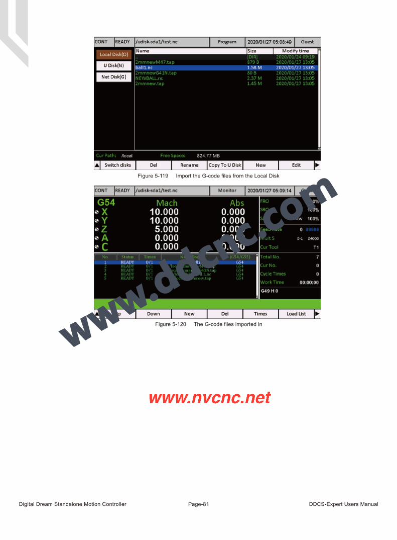
Digital Dream Standalone Motion Controller DDCS-Expert Users ManualPage-81
Figure 5-119 Import the G-code files from the Local Disk
Figure 5-120 The G-code files imported in