ddd11-9: instrumentation · ddd11-9: instrumentation this is the ddd reference document for the...
TRANSCRIPT
PDF generated on 20 Apr 2016DISCLAIMER : UNCONTROLLED WHEN PRINTED – PLEASE CHECK THE STATUS OF THE DOCUMENT IN IDM
Technical Specifications (In-Cash Procurement)
DDD11-9: Instrumentation
This is the DDD reference document for the instrumentation of magnets, feeders and structures.
IDM UID
2F2B53VERSION CREATED ON / VERSION / STATUS
25 Mar 2016 / 4.0 / Approved
EXTERNAL REFERENCE / VERSION

ITER_D_2F2B53 v4.0
Magnet Instrumentation DDD - Page 1 of 123
Remain topics to be fixed/completed/updated
Functional specs for Safety functions to update
Functional specs for Interlock functions to complete
Functional specs for cryogenic cooling to complete
Magnet grounding scheme to complete
HV wire type 2, ground shield and jacket solutions to complete
Splicing device design, qualification and production to complete
HV cable qualification procedure to complete
HV plug design, qualification and production to complete
HV feedthrough design, qualification and production to complete
HV air cable design, qualification and production to complete
HV conditioner design, qualification and production to complete
HV T sensor design, qualification and production to complete
CL heater design, qualification and production to complete
LV and optical feedthroughs design, qualification and production to complete
RT patch-panels design, qualification and production to complete
Rogowski coils design, qualification and production to complete
Specifications of the RTLV IB to finalise.
Remaining installation guidelines to issue and qualify.
AIPs to update accordingly
ITER_D_2F2B53 v4.0
Magnet Instrumentation DDD - Page 2 of 123
Table of Contents
1 INTRODUCTION......................................................................................................................................... 13
2 SCOPE ........................................................................................................................................................... 13
3 DESIGN REQUIREMENTS ....................................................................................................................... 14
3.1 OPERATION REQUIREMENTS 14
3.2 FUNCTIONAL REQUIREMENTS 15
3.2.1 Scope of the Magnet Instrumentation and Control System ................................................................ 15
3.2.2 Identification of instrumentation functional requirements ................................................................ 15
3.3 INTERFACE REQUIREMENTS 15
3.4 ENVIRONMENTAL REQUIREMENTS 16
3.5 RAMI REQUIREMENTS 16
4 WORK FLOW FROM DESIGN REQUIREMENTS TO INSTRUMENTATION COMPONENT
TECHNICAL SPECIFICATIONS – SHARED DESIGN OPTIONS .............................................................. 17
4.1 WORKFLOW OVERVIEW 17
4.2 THERMO-HYDRAULIC ANALYSIS, ELECTROMAGNETIC ANALYSIS, OPERATION REQUIREMENTS AND
FUNCTIONAL SPECIFICATIONS 17
4.3 P&IDS 19
4.3.1 Scope .................................................................................................................................................. 19
4.3.2 Production, approval workflow and repository ................................................................................. 19
4.3.3 Illustrations ........................................................................................................................................ 21
4.4 SENSOR AND ACTUATOR IDENTIFICATION AND NAMING 22
4.5 FOCUS ON QUENCH DETECTION 23
4.5.1 Primary quench detection .................................................................................................................. 23
4.5.2 Backup primary quench detection for TF .......................................................................................... 27
4.5.3 Secondary quench detection .............................................................................................................. 28
4.6 FOCUS ON THERMO-MECHANICAL BEHAVIOUR MONITORING OF STRUCTURAL ELEMENTS 29
4.7 DESIGN OPTIONS FOR THE INSTRUMENTATION CHAINS AND COMPONENT FAMILY IDENTIFICATION 30
4.7.1 HV chains - Voltage measurements ................................................................................................... 30
4.7.2 HV chains – CL heaters ..................................................................................................................... 31
4.7.3 HV chains – HV T sensor ................................................................................................................... 31
4.7.4 LV and optical chains – temperature, strain and displacement......................................................... 32
4.7.5 LV chains – pressure and flow ........................................................................................................... 32
4.7.6 LV chains – position switch ............................................................................................................... 33
4.7.7 LV chains – Rogowski coils ............................................................................................................... 33
4.7.8 LV chains – control valves ................................................................................................................. 33
4.7.9 Voltage insulating breaks .................................................................................................................. 33
4.8 SUMMARY OF THE COMPONENT FAMILIES AND PART NUMBERS 34
4.9 GROUNDING SCHEME AND EMC 36
4.9.1 HV signals .......................................................................................................................................... 36
4.9.2 LV signals from inside the cryostat .................................................................................................... 37

ITER_D_2F2B53 v4.0
Magnet Instrumentation DDD - Page 3 of 123
4.9.3 LV signals from outside the cryostat .................................................................................................. 38
4.10 MEASUREMENT CALIBRATION STRATEGY 39
4.11 MATERIAL, TECHNOLOGY AND COMPONENT QUALIFICATION STRATEGY 40
4.12 PROCUREMENT STRATEGY 41
4.13 COMPONENT LIFE-CYCLE 43
5 INSTRUMENTATION SOLUTIONS – ELEMENTARY COMPONENTS .......................................... 44
5.1 HV INSTRUMENTATION COMPONENT FAMILIES 44
5.1.1 HV connectors .................................................................................................................................... 44
5.1.2 Co-Wound Tapes: CWT ..................................................................................................................... 46
5.1.3 HV wires ............................................................................................................................................ 49
5.1.4 HV wire ground shields and jacket .................................................................................................... 52
5.1.5 HV vacuum cables ............................................................................................................................. 54
5.1.6 HV Splicing Devices .......................................................................................................................... 59
5.1.7 HV plugs ............................................................................................................................................ 61
5.1.8 HV feedthroughs ................................................................................................................................ 62
5.1.9 HV air cable ....................................................................................................................................... 65
5.1.10 HV conditioner ................................................................................................................................... 67
5.1.11 HV T sensors ...................................................................................................................................... 72
5.1.12 HV CL heaters ................................................................................................................................... 75
5.2 LV INSTRUMENTATION COMPONENT FAMILIES 78
5.2.1 LV T sensor block support, LV T sensor and LV T sensor conditioner ............................................. 78
5.2.2 Flow measurement ............................................................................................................................. 82
5.2.3 Pressure measurement – SIC pressure switches – capillary tubes & feedthroughs .......................... 87
5.2.4 Patch panels – LV patch-panels and optical patch panels ................................................................ 90
5.2.5 Trunk cables – LV and optical trunk/bundle cables .......................................................................... 93
5.2.6 LV and optical feedthroughs .............................................................................................................. 94
5.2.7 RT patch-panels ................................................................................................................................. 95
5.2.8 Rogowski coils ................................................................................................................................... 96
5.3 THERMO-MECHANICAL INSTRUMENTATION COMPONENT FAMILIES 97
5.3.1 LV displacement sensors and conditioner ......................................................................................... 97
5.3.2 LV strain gages and conditioners ...................................................................................................... 98
5.3.3 Optical T sensors and conditioners ................................................................................................... 99
5.3.4 Optical displacement sensors and conditioners............................................................................... 100
5.3.5 Optical strain gages and conditioners ............................................................................................. 101
5.3.6 Fiber optic cables for optical instrumentation ................................................................................ 102
5.4 INSULATING BREAKS COMPONENT FAMILIES 103
5.4.1 Low Temperature High Voltage Insulating Breaks (LTHV IB) ....................................................... 103
5.4.2 Room Temperature High Voltage Insulating Breaks (RTHV IB) .................................................... 105
5.4.3 Low Temperature Low Voltage Insulating Breaks (LTLV IB) ......................................................... 107

ITER_D_2F2B53 v4.0
Magnet Instrumentation DDD - Page 4 of 123
5.5 VALVES COMPONENT FAMILIES 108
6 WORK FLOW FROM COMPONENT TECHNICAL SPECIFICATIONS TO DELIVERABLES . 109
6.1 WORKFLOW OVERVIEW 109
6.1.1 Procurement contract management ................................................................................................. 109
6.2 MANUFACTURE 109
6.2.1 Procurement contract QA and QC management ............................................................................. 109
6.2.2 Scope of the IO-CT contract technical RO ...................................................................................... 109
6.3 QUALIFICATION 110
6.3.1 Qualification scope and criteria ...................................................................................................... 110
6.3.2 Performing qualification .................................................................................................................. 110
6.4 QUALITY CONTROL 111
6.4.1 QC scope and implementation ......................................................................................................... 111
6.5 DELIVERING 112
6.5.1 What to deliver, to whom and when ................................................................................................. 112
6.5.2 Delivery process .............................................................................................................................. 112
6.6 QA, QC, TECHNICAL MATERIALS AND DELIVERY TRACKING 113
6.6.1 QA and QC materials and delivery tracking ................................................................................... 113
7 WORK FLOW FROM COMPONENT DELIVERABLES TO COMMISSIONING ......................... 115
7.1 WORKFLOW OVERVIEW 115
7.2 INSTALLATION GUIDELINES AND PROCEDURES 115
7.2.1 Installation guidelines for Magnet instrumentation components..................................................... 116
7.2.2 Producing Installation procedures from guidelines ........................................................................ 117
7.2.3 Scope and Illustration of the component installation guidelines ..................................................... 117
7.2.4 Installation Quality Control ............................................................................................................. 118
7.3 ASSEMBLY AND INSPECTION PLANS (AIP) 119
7.3.1 AIPs for Magnet instrumentation components ................................................................................ 119
7.3.2 Integration of Instrumentation AIPs in Magnet system AIPs .......................................................... 120
7.3.3 Illustrations of instrumentation component AIPs ............................................................................ 121
7.4 LINKS TO COMPONENT DATABASES AND TO THE MAGNET CONTROL DDD 122
APPENDIX A ....................................................................................................................................................... 123
APPLICABLE DOCUMENTS 123
REFERENCE DOCUMENTS 123

ITER_D_2F2B53 v4.0
Magnet Instrumentation DDD - Page 5 of 123
List of Figures
Figure 1-1: Overview of the Magnet Design documentation and location of this DDD ............................................ 13
Figure 4-1: Workflow to get sensor/actuator component specifications .................................................................... 17
Figure 4-2: Illustration of coil thermo-mechanical P&ID, TF1 .................................................................................. 20
Figure 4-3: Illustration of coil and feeder electrical and hydraulic P&ID, PF1 ......................................................... 21
Figure 4-4: Voltage across DPs for TF BB compensation ......................................................................................... 25
Figure 4-5: CWT compensation for TF DPs .............................................................................................................. 25
Figure 4-6: CWT compensation for CS pancakes ...................................................................................................... 25
Figure 4-7: CDA compensation for CS DPs ............................................................................................................... 25
Figure 4-8: Generic scheme for protecting a busbar element from joint to joint ....................................................... 26
Figure 4-9: CWT arrangement for TF busbars ........................................................................................................... 26
Figure 4-10: VT arrangement for CLs ........................................................................................................................ 26
Figure 4-11: TF backup primary quench detection scheme ....................................................................................... 27
Figure 4-12: Simulation of He flow along the time for a quench at inlet (top left), outlet (top right) and middle of
TF coil (bottom).......................................................................................................................................................... 28
Figure 4-13: Chain model of HV voltage measurements ........................................................................................... 30
Figure 4-14: Chain model of the HV CL heaters........................................................................................................ 31
Figure 4-15: Chain model of the HV T sensors .......................................................................................................... 31
Figure 4-16: Chain model of the LV and optical measurements ................................................................................ 32
Figure 4-17: Chain model of the pressure and flow measurements ........................................................................... 32
Figure 4-18: Model of state position chain – They are not represented in P&IDs ..................................................... 33
Figure 4-19: Model of control valve control chain ..................................................................................................... 33
Figure 4-20: Symbol of Insulating break .................................................................................................................... 33
Figure 4-21: Grounding scheme for HV signals, single wire ground shield and HV shield not represented. ............ 36
Figure 4-22: Grounding scheme for LV signals from in cryostat ............................................................................... 37
Figure 4-23: Comparison of 3 grounding candidates for LV signal grounding, courtesy of CEA Grenoble ............. 38
Figure 4-24: Grounding scheme for LV signals from out cryostat ............................................................................. 38
Figure 4-25: Picture of the signal flow model ............................................................................................................ 39
Figure 4-26: Component life-cycle mode applicable to any Magnet instrumentation component ............................. 43
Figure 5-1: Implementation of a VT connection, (view from drawing 2FBE2W) ..................................................... 44
Figure 5-2: SC to HV wire connection ....................................................................................................................... 45
Figure 5-3: CWT to HV wire connection ................................................................................................................... 45
Figure 5-4: Illustrations of the mechanical and electrical HV connector qualification tests. ..................................... 45
Figure 5-5: Illustration of CWT implementation: the TF cable insulation ................................................................. 46
Figure 5-6: Illustration of CWT implementation: the bus bars. ................................................................................. 46
Figure 5-7: Illustration of CWT type 1 (left) and type 2 (right) ................................................................................. 48
Figure 5-8: Illustration of CWT type 1 wrapping on a TF conductor. ....................................................................... 48
Figure 5-9: Illustration of CWT type 2 tensile test. .................................................................................................... 48
Figure 5-10: Illustration of CWT wrapping trials at ELYTT ..................................................................................... 48
ITER_D_2F2B53 v4.0
Magnet Instrumentation DDD - Page 6 of 123
Figure 5-11: Extract from HV wiring scheme. Coil and TF Feeders (9FY7HS v1.4 and 1101WP_003397 : TF WP
insulation (2FBE2W) .................................................................................................................................................. 49
Figure 5-12: Forming twisted triplets (TF configuration) .......................................................................................... 49
Figure 5-13: Illustration of a HV wire 1 spool. .......................................................................................................... 51
Figure 5-14: Pictures of the chemical compatibility tests (courtesy of MARTI SUPRATECH) ............................... 52
Figure 5-15: Twisted wires with ground shields and jacket layout – Quintuplet, quadruplet, triplet and pair ........... 52
Figure 5-16: Overview of the HV cable routing – TF illustration .............................................................................. 54
Figure 5-17: Illustration of the HV wire - HV cable connection schemes: TF coils. ................................................. 54
Figure 5-18: Illustration of HV vacuum cable configuration – type 2 ....................................................................... 55
Figure 5-19: Illustration of HV vacuum cable spool and picture of the stripping test ............................................... 58
Figure 5-20: Illustration of HV splicing device in the TF terminal area – Extract from P5SMHV drawing ............. 59
Figure 5-21: Draft design of the HV splicing device.................................................................................................. 60
Figure 5-22: Location of the HV plugs on extension pipes from the VB in the SBB ................................................ 61
Figure 5-23: Draft design of the HV plug .................................................................................................................. 61
Figure 5-24: Instrumentation satellite and feedthrough location. ............................................................................... 62
Figure 5-25: Picture of the HV feedthrough and air plug ........................................................................................... 63
Figure 5-26: 30 kV – 6 pins HV feedthrough cross section – vacuum cable interface part. ...................................... 63
Figure 5-27: Illustration of HV air cable configuration – type 2 ................................................................................ 65
Figure 5-28: Functional diagram of the primary Quench Detection System .............................................................. 68
Figure 5-29: Functional diagram of the HV conditioner ............................................................................................ 68
Figure 5-30: Functional diagram of the HV conditioner (CS version) ....................................................................... 68
Figure 5-31: Analogue front end diagram – principles............................................................................................... 69
Figure 5-32: Analogue front end diagram – details for TF......................................................................................... 70
Figure 5-33: Functional location of the HV T sensors ............................................................................................... 72
Figure 5-34: Physical location of the HV T sensors ................................................................................................... 72
Figure 5-35: Wiring the HV T sensors ....................................................................................................................... 73
Figure 5-36: Configuration of the T sensor wire extraction from the CL in the terminal area. .................................. 73
Figure 5-37: Functional diagrams of the HV T conditioner. ...................................................................................... 74
Figure 5-38: Dry box, transparent view ...................................................................................................................... 75
Figure 5-39: View of the warm CL terminal on the 68 kA lead ................................................................................. 75
Figure 5-40: sketch of the HV insulated heating cartridge ......................................................................................... 76
Figure 5-41: Breakdown of the T sensor components – pipe fixing solution, ............................................................ 78
Figure 5-42: Cross section of T sensor – flat surface pipe fixing solution, courtesy of CEA Grenoble .................... 78
Figure 5-43: Assembly of the main components (1: cover plate; 2: PCB; 3: copper heat sink; 4: block support),
courtesy of CEA Grenoble ......................................................................................................................................... 78
Figure 5-44: Thermometric blocks mounted on welded studs, with and without thermal shield. .............................. 79
Figure 5-45: Modelling of the thermal flow of the thermometric block. The number and sizes of the arrows
represent the intensity of the loads. Courtesy of CEA Grenoble ................................................................................ 79
Figure 5-46: 19” crate including ................................................................................................................................. 79
Figure 5-47: Cable layout, 1 = twisted wire, 2 = braided ground shield, 3&4 Insulation layers ................................ 80
ITER_D_2F2B53 v4.0
Magnet Instrumentation DDD - Page 7 of 123
Figure 5-48: The experimental test cryostat: design and components, courtesy of CEA Grenoble ........................... 81
Figure 5-49: validation @ 4.2 K and 80 K of ITER requirements, courtesy of CEA Grenoble ................................. 82
Figure 5-50: Identification of flow measurement in P&IDs ....................................................................................... 82
Figure 5-51: Illustration of a Venturi tube for TF, courtesy of CEA Grenoble .......................................................... 83
Figure 5-52: Differential pressure versus pressure tap position along the VT at different steps of time after a TF
quench event, courtesy of CEA Grenoble .................................................................................................................. 84
Figure 5-53: Predicted flow measurement accuracy versus flow rate for the DN25 400 g/s VTs ............................. 85
Figure 5-54: VT leak test facility, courtesy of CEA Grenoble ................................................................................... 86
Figure 5-55: HELIOS cold test facility, courtesy of CEA Grenoble .......................................................................... 86
Figure 5-56: Configuration of VT testing in the HELIOS test facility: 3 parallel branches equipped with 3 VTs and
a Coriolis flowmeter downstream. .............................................................................................................................. 86
Figure 5-54: Illustration of potential differential pressure transmitter and switch products ...................................... 87
Figure 5-55: Picture of the magnetic field test facility, courtesy of CEA Grenoble .................................................. 90
Figure 5-56: LV cabling scheme in vacuum area ....................................................................................................... 90
Figure 5-57: Electrical connection scheme for LV cables into the LV PP ................................................................. 91
Figure 5-58: Picture of LV patch panel ...................................................................................................................... 91
Figure 5-59: LV PP drawing ...................................................................................................................................... 91
Figure 5-60: Optical patch-panel and splice tray layouts. .......................................................................................... 92
Figure 5-61: Splice tray arrangement. ........................................................................................................................ 92
Figure 5-62: General cabling scheme for instrumentation air cables. ........................................................................ 95
Figure 5-63: Illustration of Rogowski coil, courtesy of NFRI - KSTAR ................................................................... 96
Figure 5-64: Illustration of LV displacement sensor and support .............................................................................. 97
Figure 5-65: Illustration of LV displacement sensor location in feeders to monitor the thermal contraction of the
busbars ........................................................................................................................................................................ 97
Figure 5-66: Illustration of LV strain gage and support ............................................................................................ 98
Figure 5-67: Illustration of optical T sensor ............................................................................................................... 99
Figure 5-68: Illustration of optical displacement sensor (left 40 mm range FP, right 3 mm range FBG) ................ 100
Figure 5-69: Illustration of optical strain gage ......................................................................................................... 101
Figure 5-70: Schematic arrangement of ITER Axial Insulating Break .................................................................... 103
Figure 5-71: Functional location of LTHV IBs for TF coils (red doted circles) ...................................................... 103
Figure 5-72: Illustration of LTHV 30 kV IB ............................................................................................................ 104
Figure 5-73: Functional location of RTHV IBs for TF coils (red doted circles) ...................................................... 105
Figure 5-74: Functional location of LTLV IBs ........................................................................................................ 107
Figure 5-75: Illustration of LTLV IBs ...................................................................................................................... 107
Figure 6-1: Results of fiber optic cable radiation qualification at CERN –courtesy of CERN ................................ 110
Figure 6-2: Picture of the Magnet HV test facility at CEA Cadarache – Courtesy of CEA Cadarache ................... 110
Figure 6-3: Picture of optical sensor test facility @ 4K –courtesy of CEA SBT ..................................................... 111
Figure 6-4: Picture of the LV T sensor test facility –courtesy of CEA SBT ............................................................ 111
Figure 6-5: Illustration of MIP for the CWT production .......................................................................................... 111
Figure 6-6: Magnet instrumentation routing model .................................................................................................. 112
ITER_D_2F2B53 v4.0
Magnet Instrumentation DDD - Page 8 of 123
Figure 6-7: Picture of the Magnet instrumentation shipment work-flow ................................................................. 112
Figure 6-8: Illustration of MMD tracking features for a Magnet T sensor Pt 100 kit part ....................................... 113
Figure 6-9: Illustration of MMD tracking features for shipments ............................................................................ 114
Figure 7-1: Overview of the Magnet instrumentation life-cycle up to Installation and testing. ............................... 115
Figure 7-2: Workflow to get qualified installation procedures ................................................................................. 115
Figure 7-3: Pictures extracted from the component installation guidelines ............................................................. 117
Figure 7-4: Magnet I&C AIP workflow overview ................................................................................................... 120
Figure 7-5: Magnet Instrumentation DDD and Control DDD boundary .................................................................. 122
List of Tables
Table 1: Magnet instrumentation environmental conditions ........................................................................................................ 16
Table 2: Functional specifications for Magnet I&C ..................................................................................................................... 18
Table 3: Magnet P&IDs ............................................................................................................................................................... 20
Table 4: List of sensors and actuators identified throughout the P&IDs ...................................................................................... 22
Table 5: Symbols of sensors and actuators as used ...................................................................................................................... 23
Table 6: QD redundancy strategy ................................................................................................................................................. 26
Table 7: List of instrumentation product families and component part number ........................................................................... 35
Table 8: Instrumentation component procurement strategy ......................................................................................................... 42
Table 9: Technical specification of the HV connectors ................................................................................................................ 45
Table 10: Technical specification of the CWT ............................................................................................................................. 47
Table 11: Technical specification of the HV wires: electrical performance requirements ........................................................... 50
Table 12: Technical specification of the HV wires: mechanical performance requirements ....................................................... 50
Table 13: Technical specification of the HV wires: conductor specifications – Centricity of insulation is > 70 % .................... 51
Table 14: Wire twisting arrangements for all Magnet sub-systems. ............................................................................................ 52
Table 15: Technical specifications of the wire ground shields and jacket ................................................................................... 53
Table 16: HV vacuum cable types ............................................................................................................................................... 56
Table 17: Electrical performance requirements for the HV vacuum cables ................................................................................. 57
Table 18: Mechanical/Physical performance requirements for the HV vacuum cables ............................................................... 57
Table 19: HV vacuum cables total length per cable type ............................................................................................................. 58
Table 20: Non-electrical requirements for the HV plugs ............................................................................................................. 60
Table 21: HV vacuum cables total length per cable type ............................................................................................................. 60
Table 22: Non-electrical requirements for the HV plugs ............................................................................................................. 62
Table 23: Electrical performance requirements for the HV feedthroughs .................................................................................... 64
Table 24: Non-electrical requirements for the HV feedthroughs ................................................................................................. 64
Table 25: HV feedthroughs quantities per type ............................................................................................................................ 64
Table 26: HV air cable types ........................................................................................................................................................ 66
Table 27: Electrical performance requirements for the HV air cables ......................................................................................... 66
Table 28: Mechanical - Physical performance requirements for the HV air cables ..................................................................... 67
Table 29: HV air ........................................................................................................................................................................... 67
Table 30: Input signal range for HV conditioners ........................................................................................................................ 70
Table 31: Heating cartridges technical specifications .................................................................................................................. 76
ITER_D_2F2B53 v4.0
Magnet Instrumentation DDD - Page 9 of 123
Table 32: Power unit technical specifications .............................................................................................................................. 77
Table 33: VT nominal flowrate specifications at nominal operation ........................................................................................... 84
Table 34: Minimum length of straight pipe upstream to the VT .................................................................................................. 85
Table 35: Specifications for the absolute pressure transducers .................................................................................................... 88
Table 36: Specifications for the differential pressure transducers ................................................................................................ 88
Table 37: Specifications for the differential pressure transducers ................................................................................................ 89
Table 38: Specifications for the differential pressure transducers ................................................................................................ 89
Table 39: vacuum and air capillary tube specifications ................................................................................................................ 89
Table 40: LV trunk cable specifications ....................................................................................................................................... 93
Table 41: Optical bundle cable specifications .............................................................................................................................. 93
Table 42: Electrical performance requirements for the LTHV IBs ............................................................................................ 104
Table 43: Mechanical performance requirements for the LTHV IBs ......................................................................................... 104
Table 44: Other requirements for the LTHV IBs ....................................................................................................................... 104
Table 45: LTHV IB quantities per type ...................................................................................................................................... 104
Table 46: Electrical performance requirements for the RTHV IBs ............................................................................................ 106
Table 47: Mechanical performance requirements for the RTHV IBs ........................................................................................ 106
Table 48: Other requirements for the RTHV IBs ....................................................................................................................... 106
Table 49: RTHV IB quantities per type ..................................................................................................................................... 106
Table 50: Technical requirements for the LTLV IBs ................................................................................................................. 107
Table 51: Valve components and amounts ................................................................................................................................. 108
Table 52: Magnet instrumentation guidelines ............................................................................................................................ 116
Table 53: QC at component installation ..................................................................................................................................... 118
Table 54: Magnet instrumentation AIPs ..................................................................................................................................... 119
Table 55: AIP for the LV T sensor installation .......................................................................................................................... 121
ITER_D_2F2B53 v4.0
Magnet Instrumentation DDD - Page 10 of 123
Acronyms
BB Balanced Bridge
CAD Computer Aided Design
CBN Common Bonding Network
CC Correction Coil
CD Cryo-Distribution
CDA Central Difference Averaging
CER Continuous External Rogowski
CFT Cryostat Feedthrough
CIS Central Interlock System
CL Current Lead
COTS Commercial Off-The-Shelf
CS Central Solenoid (coil)
CTB Cold Termination Box
CWT Co-Wound Tape
DA Domestic Agency
DB Dry Box
DC Direct Current
DP Double Pancake
DR Deviation Request
EDB Engineering Data Base
EDH Electrical Design Handbook
EMC Electro-Magnetic Compatibility
EMI Electro-Magnetic Interference
EQDD Electronic Quench Detection Device
FAT Factory Acceptance Test
FB Field-Bus
FBG Fiber Bragg Grating
FDU Fast Discharge Unit
FP Fabry-Perot
FS Full Scale
GHe Gaseous Helium
HTS High Temperature Superconductor
HV High Voltage
IB Insulating Break
ICF In-Cryostat-Feeder
ID Inner Diameter
IDM Iter Document Management
I&C Instrumentation and Control
IO ITER Organization
IO-CT IO Central Team
IS Interface Sheet

ITER_D_2F2B53 v4.0
Magnet Instrumentation DDD - Page 11 of 123
ISA International Society of Automation
ISO International Standards Organization
ITER International Thermonuclear Experimental Reactor
LT Low temperature
LV Low Voltage
MAG Magnet Control group
MCR Main Control Room
MQP Management and Quality Program
MIK Mik Mutual inductance between ith and k
th component
MIP Manufacture Inspection Plan
MMD Magnet Manufacture Database
NA Non Applicable
NCR Non Conformity Report
NDA Non-Disclosure Agreement
NDT Non Destructive Tests
OS Occupational Safety
OD Outer Diameter
P&ID Process and Instrumentation Diagram
PA Procurement Arrangement
PBS Plant Breakdown Structure
PCB Printed Circuit Board
PCDH Plant Control Design Handbook
PCS Plasma Control System
PD Paschen Discharge
PF Poloidal Field (coil)
PFD Process Flow Diagram
PI Polyimide
PRVR Pressure Release Valve Rack
PSP Plant System Database
QA Quality Assurance
QC Quality Control
QD Quench Detector
RAMI Reliability, Availability, Maintainability and Inspectability
RO Responsible Officer
RT Room Temperature
RTD Resistance Temperature Detector
S-ICD System Interface Control Document
SAT Site Acceptance Test
SBB S Bend Box
SC Superconductive Conductor
SCVB Structure Cooling Valve Box
SHe Supercritical Helium
SIC Safety Importance Class
ITER_D_2F2B53 v4.0
Magnet Instrumentation DDD - Page 12 of 123
SIL Safety Integrity Level
SP Single Pancake
SRD System Requirements Document
SSD See System Design database
SW Software
TBC To be Confirmed
TBD To Be Defined, To Be Done
TF Toroidal Field (coil)
Tg Glass Transition temperature
UL Unit Lenght
VB Vacuum Barrier
VT Voltage Tap – Venturi Tube
ITER_D_2F2B53 v4.0
Magnet Instrumentation DDD - Page 13 of 123
1 Introduction
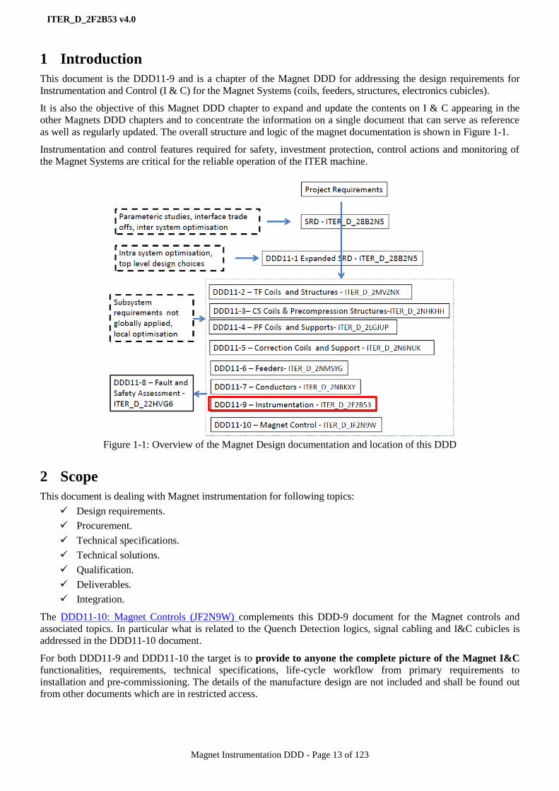
This document is the DDD11-9 and is a chapter of the Magnet DDD for addressing the design requirements for
Instrumentation and Control (I & C) for the Magnet Systems (coils, feeders, structures, electronics cubicles).
It is also the objective of this Magnet DDD chapter to expand and update the contents on I & C appearing in the
other Magnets DDD chapters and to concentrate the information on a single document that can serve as reference
as well as regularly updated. The overall structure and logic of the magnet documentation is shown in Figure 1-1.
Instrumentation and control features required for safety, investment protection, control actions and monitoring of
the Magnet Systems are critical for the reliable operation of the ITER machine.
Figure 1-1: Overview of the Magnet Design documentation and location of this DDD
2 Scope
This document is dealing with Magnet instrumentation for following topics:
Design requirements.
Procurement.
Technical specifications.
Technical solutions.
Qualification.
Deliverables.
Integration.
The DDD11-10: Magnet Controls (JF2N9W) complements this DDD-9 document for the Magnet controls and
associated topics. In particular what is related to the Quench Detection logics, signal cabling and I&C cubicles is
addressed in the DDD11-10 document.
For both DDD11-9 and DDD11-10 the target is to provide to anyone the complete picture of the Magnet I&C
functionalities, requirements, technical specifications, life-cycle workflow from primary requirements to
installation and pre-commissioning. The details of the manufacture design are not included and shall be found out
from other documents which are in restricted access.
0

ITER_D_2F2B53 v4.0
Magnet Instrumentation DDD - Page 14 of 123
3 Design Requirements
This chapter elaborates on the primary design requirements to consider for the Magnet Instrumentation: the
operation requirements, the functional requirements, the interface requirements and the environmental
requirements.
These requirements are extracted from the set of documents mentioned in the document introduction and a bit
expanded in below sections.
3.1 Operation requirements
[S1] The Magnet system is operated during Short Term Maintenance (STM), Test and Conditioning (TCS) and
Plasma Operation (POS). The Magnet system is locked in Safe state during the Long Term Maintenance
(LTM) of ITER.
[S2] The Magnet system is commissioned under the Magnet RO responsibility before being used for ITER plant
operation in scope of Plant Conditioning and Plasma Operation.
[S3] The Magnet system is protected by a set of Interlock and Safety functions implemented in the relevant
Interlock and Safety systems for appropriate actions in the Magnet system and other plant systems. The
Magnet control system is responsible for detecting, alarming and transmitting the Magnet Interlock and
Safety events only.
[S4] The Magnet system is fully operated by the Magnet operators from the Main Control Room (MCR) for
following operation scope:
Magnet system monitoring and alarming during Magnet cool down and warm up.
Magnet system pre-commissioning before powering.
Magnet system monitoring and alarming during powering.
Magnet system quality assurance and failure analysis (e.g. quench or fast discharge).
[S5] The Magnet system is powered by the Coil Power Supplies System (PBS41) for magnet energizing and de-
energizing under the ITER plant Operation authority for all Magnet System operating states.
[S6] The Magnet System is cooled down, kept in cryogenic operation condition and warmed-up by the
Cryogenic System (PBS34) under the ITER plant Operation authority for all Magnet System operating
states.
[S7] It is not the role of the Magnet operator to set up the magnet currents, to check the magnet current
configuration and to control the magnet cooling but it is his role and responsibility to monitor and alarm the
Magnet system for following scope:
Mechanical behaviour of magnet structural elements.
Electromagnetic behaviour of coils, feeders and current leads.
Thermo-hydraulic behaviour of coils, bus-bars and current leads.
Quench detection systems of coils, jumpers, bus-bars and current leads.
Magnet interface with other systems.

ITER_D_2F2B53 v4.0
Magnet Instrumentation DDD - Page 15 of 123
3.2 Functional requirements
3.2.1 Scope of the Magnet Instrumentation and Control System
Derived from the operation requirements expressed in the section 3.1, the Magnet control system scope is:
For pre-commissioning and commissioning the Magnet System:
To perform the Magnet System test procedure for the scope concerned by the Magnet control system.
For operating the Magnet System:
To implement the N-Safety functions assigned to the Magnet system.
To detect the quench events in coils, jumpers, bus bars and current leads. In case of quench event, trigger a
protective energy discharge as part of a Magnet system protection.
To monitor the electromagnetic behaviour of the coils.
To monitor the thermo-mechanical behaviour of structural elements which are considered as critical for the
integrity of the Magnet System.
To control the Magnet cryogenic cooling and protect the Magnet system against any cooling and vacuum
failure.
To provide the data set including pre-triggered data in scope of Magnet failure analysis.
3.2.2 Identification of instrumentation functional requirements
This section provides an overview of the instrumentation functional requirements; the control requirements are
addressed in the DDD11-10: Magnet Controls (JF2N9W). Following functional requirements shall be considered
for the Magnet instrumentation:
Instrumentation related to Safety (N-Safety):
The flow measurements required to implement the TF magnet fast discharge safety I&C function.
The state and control signals related to the burst discs, the pressure relief valves and control valves required
to implement the Cryogenic distribution circuit isolation.
The quench valve state signals required to implement the cryogenic circuit pressure relief monitoring.
Instrumentation related to the Magnet system protection (Interlock):
The coil, busbar, and current lead voltage measurements required to implement the primary quench
detection for all Magnet systems.
The Quench Detection System (QDS) state signals.
The coil, busbar, and current lead cryogenic measurements required to detect any cooling failure.
The CTB and SCVB vacuum measurements required to detect any loss of vacuum.
Instrumentation related to the electromagnetic behaviour monitoring and failure analysis:
This scope is matching the primary quench detection scope completed with some data to be provided by the
PBS41 (e.g. magnet currents, power supply states, FDU states, …).
Instrumentation related to magnet thermo-mechanical behaviour monitoring of structural elements:
The temperature, strain and displacement measurements required in the thermo-mechanical behaviour
monitoring of the structural elements of the coils and structures.
Instrumentation related to cryogenic controls and monitoring:
The temperature, pressure, flow measurements, electric heater control, valve control and any state signal
required to monitor and control the Magnet cryogenic operation (PBS11 scope only)
3.3 Interface requirements
The Magnet instrumentation is made of sensors and actuators. These sensors and actuators are all integrated in the
Magnet sub-systems: TF, CS, PF, CC coils and feeders. The detailed integration is elaborated in the Magnet sub-
system design materials and therefore is addressed in this DDD for main principles only, see the section 7.
There is no direct interface of any Magnet instrumentation component to any other ITER plant system: These
components are connected to the Magnet I&C controllers only and these controllers are interfaced to the CODAC
ITER_D_2F2B53 v4.0
Magnet Instrumentation DDD - Page 16 of 123
networks. Therefore the functional interfaces of the Magnet system with other ITER plant systems are implemented
through CODAC; see the DDD11-10: Magnet Controls (JF2N9W) for further details about.
3.4 Environmental requirements
The ITER environmental conditions are specified in the reference document [RD8]. In addition, ITER EMC and
radiation policy as specified in [AD5] applies.
The Magnets thermo-mechanical and cryogenic instrumentation (sensors, wires and cables) shall be insensitive to
radiation and to magnetic fields. These can result in effective transmission rate and degradation or failures of
instrumentation signals from sensors.
The Magnets HV instrumentation shall be insensitive to radiation sources. These can result in degradation of the
voltage insulation, mechanical properties and activation of materials.
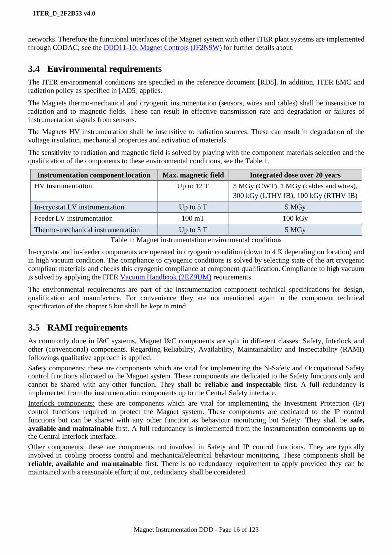
The sensitivity to radiation and magnetic field is solved by playing with the component materials selection and the
qualification of the components to these environmental conditions, see the Table 1.
Instrumentation component location Max. magnetic field Integrated dose over 20 years
HV instrumentation Up to 12 T 5 MGy (CWT), 1 MGy (cables and wires),
300 kGy (LTHV IB), 100 kGy (RTHV IB)
In-cryostat LV instrumentation Up to 5 T 5 MGy
Feeder LV instrumentation 100 mT 100 kGy
Thermo-mechanical instrumentation Up to 5 T 5 MGy
Table 1: Magnet instrumentation environmental conditions
In-cryostat and in-feeder components are operated in cryogenic condition (down to 4 K depending on location) and
in high vacuum condition. The compliance to cryogenic conditions is solved by selecting state of the art cryogenic
compliant materials and checks this cryogenic compliance at component qualification. Compliance to high vacuum
is solved by applying the ITER Vacuum Handbook (2EZ9UM) requirements.
The environmental requirements are part of the instrumentation component technical specifications for design,
qualification and manufacture. For convenience they are not mentioned again in the component technical
specification of the chapter 5 but shall be kept in mind.
3.5 RAMI requirements
As commonly done in I&C systems, Magnet I&C components are split in different classes: Safety, Interlock and
other (conventional) components. Regarding Reliability, Availability, Maintainability and Inspectability (RAMI)
followings qualitative approach is applied:
Safety components: these are components which are vital for implementing the N-Safety and Occupational Safety
control functions allocated to the Magnet system. These components are dedicated to the Safety functions only and
cannot be shared with any other function. They shall be reliable and inspectable first. A full redundancy is
implemented from the instrumentation components up to the Central Safety interface.
Interlock components: these are components which are vital for implementing the Investment Protection (IP)
control functions required to protect the Magnet system. These components are dedicated to the IP control
functions but can be shared with any other function as behaviour monitoring but Safety. They shall be safe,
available and maintainable first. A full redundancy is implemented from the instrumentation components up to
the Central Interlock interface.
Other components: these are components not involved in Safety and IP control functions. They are typically
involved in cooling process control and mechanical/electrical behaviour monitoring. These components shall be
reliable, available and maintainable first. There is no redundancy requirement to apply provided they can be
maintained with a reasonable effort; if not, redundancy shall be considered.

ITER_D_2F2B53 v4.0
Magnet Instrumentation DDD - Page 17 of 123
4 Work flow from design requirements to instrumentation component
technical specifications – Shared design options
This chapter elaborates on how the Magnet instrumentation components have been identified and about the shared
design options which were used to get some component design consistency.
4.1 Workflow overview
For dealing with technical specifications for manufacture the work flow scheme of the Figure 4-1 was applied to
any Magnet sensor and actuator. The workflow starting point is obviously the set of thermohydraulic and
electromagnetic analysis and operation requirements which is needed to capture a comprehensive picture of the
Magnet system operation.
From that point a set of Magnet I&C functional specifications was issued for defining how the Magnet system will
be monitored, protected and controlled. These functional specifications were implemented in PFD and P&IDs
drawings. RAMI requirements were considered at this stage for the redundancy requirements. Today for resource
optimisation only the P&IDs are kept updated.
Then the sensors and actuators were identified as measurement chains; the performance and the design options
were defined; families of components identified and a part number assigned to each family.
In the meantime some R&D programs were conducted for qualifying the proper technology to be used for
component production.
The last step was to compute everything for issuing the component technical specifications and then be able to
move to the component contract call for tenders. The Figure 4-1 provides the general picture of this workflow
while the section 4.13 elaborates on the individual component life-cycle.
Figure 4-1: Workflow to get sensor/actuator component specifications
4.2 Thermo-hydraulic analysis, electromagnetic analysis, operation requirements
and functional specifications
The analysis inputs and the operation requirements are extracted from the Magnet Design documentation
mentioned into the chapter 1 and from statements given in the sections 3.1 and 3.2.
The Magnet I&C functional specifications are listed in the Table 2. They address the Instrumentation and Control
requirements and are introduced in this DDD as inputs for the instrumentation components technical specifications.
These Magnet I&C functional specifications are further elaborated in the DDD11-10: Magnet Controls (JF2N9W).
Functional specs
Implementation in P&IDs
Instrumentation requirements
Measurement chainsIdentification and
performance requirements
R&D activities, proof of concept, prototypes
Instrumentation component tech
specs
Thermohydraulic analysis
Operation requirements
Design options
Environmental conditionsRAMI
Qualified technology
Electromagnetic analysis
Component family identification

ITER_D_2F2B53 v4.0
Magnet Instrumentation DDD - Page 18 of 123
Functional specification Comment
Functions related to N-Safety
TF magnets Fast Discharge safety I&C function
(6QCZT5)
To update regarding the pressure sensor technology
I&C safety functions specification for the magnet
cryogenic distribution circuit isolation (BKNKKE)
Draft versions.
The attached Safety requirements are specified in:
Tokamak building cryocircuits safety criteria
(JQTGEH I&C safety function specification for Magnet
cryogenic circuit pressure relief (F59A4N)
Functions related to Investment Protection
Central Interlock System Strategy for ITER Magnet
Protection: Machine Protection Functions (K7G8GN)
Provides the fast discharge overview including coil
power supplies and CIS
Principle of Quench Detection In TF (PHTQM2) Final and approved version. The complete scheme of
the primary Quench Detection is elaborated in
DDD11-10: Magnet Controls (JF2N9W) Principle of Quench Detection in CS (N5UYMR)
1
Principle of Quench Detection in PF (PJ37K3)
Principle of Quench Detection In CC (N9R6TT)
Principle of Quench Detection in the Feeders and
Jumpers (Q4JLUB)
Specification for the Operation, Controls and Interlock
Strategies for the ITER HTS CL (48VMWM)
Secondary quench detection Based on flow measurements for coils and T
measurements for busbars. The details are still TBD
Overcurrent protection PBS41scope since implemented in power supplies
Unbalanced forces from inappropriate coil currents Plasma Control System (PCS) scope
Magnet dependencies for fast discharges Central Interlock System (CIS) scope
Loss of He cooling (LOFA) detected from Flow
measurements
The needed instrumentation is there, the functional
specs are still TBD
Overheating detected from T measurements
Loss of voltage insulation to the ground Details are still TBD
Functions related to conventional control and monitoring
Mechanical instrumentation of the TF, CS, CC, PF coil
structures (2LHDXW)
Initial version of requirements for the thermo-
mechanical monitoring
Functional requirements of the thermo-mechanical
instrumentation on TF coil structures (Q8ZZ3C)
Amendment of the thermo-mechanical monitoring for
TF
DR No. 10: CS Structure Instrumentation Changes
(PTJJE8)
Amendment of the thermo-mechanical monitoring for
CS
Electromagnetic behaviour monitoring and failure
analysis: see the section 3 of the Magnet control
DDD-10 (JF2N9W),
The tools required for failure analysis are still TBD.
Cryogenic control and monitoring., see the section 3
of the Magnet control DDD-10 (JF2N9W). The CL
control and monitoring is addressed in (48VMWM)
Details to incorporate to: Functional Analysis of the
Cryo-distribution System (GDPH37).
TF CER data acquisition: see the section 3 of the
Magnet control DDD-10 (JF2N9W)
The CER coils are in the PBS55 scope. PBS11
provides the signal and the data handling only.
Table 2: Functional specifications for Magnet I&C
1 Summary of CS Quench Detection Study (QDS) Instrumentation Requirements (HY3T2S)
ITER_D_2F2B53 v4.0
Magnet Instrumentation DDD - Page 19 of 123
4.3 P&IDs
4.3.1 Scope
The Magnet P&IDs are the 2D diagrams showings the electrical and hydraulic circuits running within the Magnet
system up to the PBS41 and PBS34 interfaces.
To get a complete picture of these circuits the coil and the attached feeder are represented on the same diagram.
The boundary of the PAs involved in is shown by coloured dash lines.
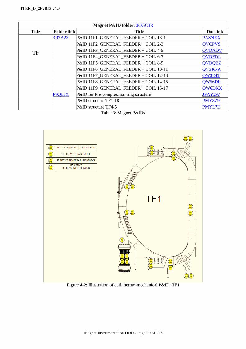
By extension of the P&ID scope and for convenience, 2D diagrams have been issued for specifying the type and
location of the thermo-mechanical instrumentation.
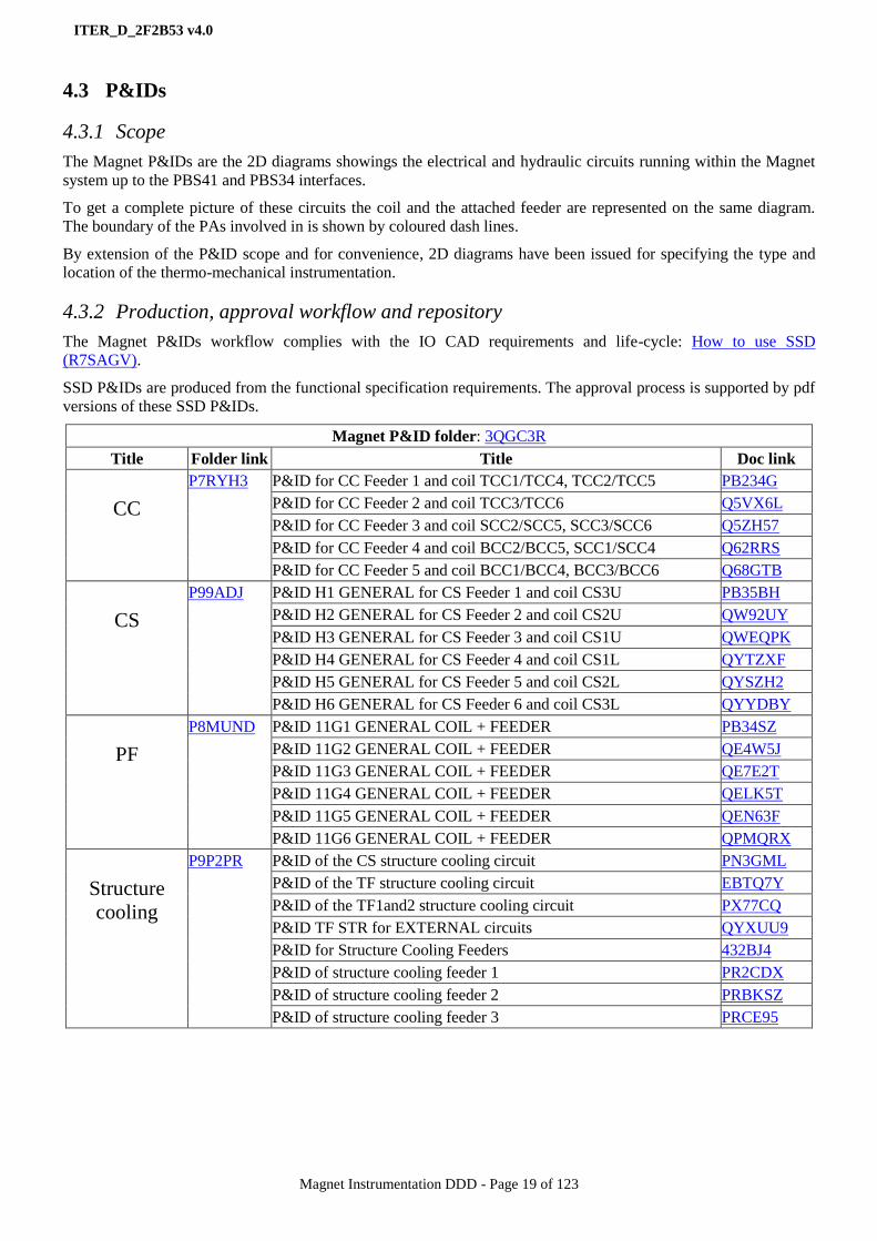
4.3.2 Production, approval workflow and repository
The Magnet P&IDs workflow complies with the IO CAD requirements and life-cycle: How to use SSD
(R7SAGV).
SSD P&IDs are produced from the functional specification requirements. The approval process is supported by pdf
versions of these SSD P&IDs.
Magnet P&ID folder: 3QGC3R
Title Folder link Title Doc link
CC
P7RYH3 P&ID for CC Feeder 1 and coil TCC1/TCC4, TCC2/TCC5 PB234G
P&ID for CC Feeder 2 and coil TCC3/TCC6 Q5VX6L
P&ID for CC Feeder 3 and coil SCC2/SCC5, SCC3/SCC6 Q5ZH57
P&ID for CC Feeder 4 and coil BCC2/BCC5, SCC1/SCC4 Q62RRS
P&ID for CC Feeder 5 and coil BCC1/BCC4, BCC3/BCC6 Q68GTB
CS
P99ADJ P&ID H1 GENERAL for CS Feeder 1 and coil CS3U PB35BH
P&ID H2 GENERAL for CS Feeder 2 and coil CS2U QW92UY
P&ID H3 GENERAL for CS Feeder 3 and coil CS1U QWEQPK
P&ID H4 GENERAL for CS Feeder 4 and coil CS1L QYTZXF
P&ID H5 GENERAL for CS Feeder 5 and coil CS2L QYSZH2
P&ID H6 GENERAL for CS Feeder 6 and coil CS3L QYYDBY
PF
P8MUND P&ID 11G1 GENERAL COIL + FEEDER PB34SZ
P&ID 11G2 GENERAL COIL + FEEDER QE4W5J
P&ID 11G3 GENERAL COIL + FEEDER QE7E2T
P&ID 11G4 GENERAL COIL + FEEDER QELK5T
P&ID 11G5 GENERAL COIL + FEEDER QEN63F
P&ID 11G6 GENERAL COIL + FEEDER QPMQRX
Structure
cooling
P9P2PR P&ID of the CS structure cooling circuit PN3GML
P&ID of the TF structure cooling circuit EBTQ7Y
P&ID of the TF1and2 structure cooling circuit PX77CQ
P&ID TF STR for EXTERNAL circuits QYXUU9
P&ID for Structure Cooling Feeders 432BJ4
P&ID of structure cooling feeder 1 PR2CDX
P&ID of structure cooling feeder 2 PRBKSZ
P&ID of structure cooling feeder 3 PRCE95
ITER_D_2F2B53 v4.0
Magnet Instrumentation DDD - Page 20 of 123
Magnet P&ID folder: 3QGC3R
Title Folder link Title Doc link
TF
3R7A2S P&ID 11F1_GENERAL_FEEDER + COIL 18-1 PASNXX
P&ID 11F2_GENERAL_FEEDER + COIL 2-3 QVCPVS
P&ID 11F3_GENERAL_FEEDER + COIL 4-5 QVDADV
P&ID 11F4_GENERAL_FEEDER + COIL 6-7 QVDFDL
P&ID 11F5_GENERAL_FEEDER + COIL 8-9 QVDQEZ
P&ID 11F6_GENERAL_FEEDER + COIL 10-11 QVZKPA
P&ID 11F7_GENERAL_FEEDER + COIL 12-13 QW3DJT
P&ID 11F8_GENERAL_FEEDER + COIL 14-15 QW56DR
P&ID 11F9_GENERAL_FEEDER + COIL 16-17 QW6DKX
P9QLJX
P&ID for Pre-compression ring structure JFAY2W
P&ID structure TF1-18 PMY8Z9
P&ID structure TF4-5 PMYL7H
Table 3: Magnet P&IDs
Figure 4-2: Illustration of coil thermo-mechanical P&ID, TF1

ITER_D_2F2B53 v4.0
Magnet Instrumentation DDD - Page 21 of 123
4.3.3 Illustrations
Figure 4-3: Illustration of coil and feeder electrical and hydraulic P&ID, PF1

ITER_D_2F2B53 v4.0
Magnet Instrumentation DDD - Page 22 of 123
4.4 Sensor and actuator identification and naming
After identification in P&IDs the sensors and actuators are named. The ITER naming convention: ITER
Numbering System for Components and Parts (28QDBS) applies on the PBS and TTT codes identifiers.
The document Update of Magnet PBS and Part Names (Q7N328) applies on the NNNN numbers.
The Table 4 provides the list of the sensors and actuators which are identified throughout the P&IDs.
Sensor and actuators Primary scope and link to the instrumentation scope TTT code
High Voltage
Electrical measurements Primary quench detection and electromagnetic behaviour
monitoring.
ME
Electrical breaks Cryogenic circuit voltage insulation2. EIB
Temperature sensor Monitor and interlock the HTS current leads MT
Low Voltage
Temperature sensors Monitor the thermo-mechanical behaviour of structures and
control the Magnet cryogenic cooling.
MT and
MTO
Pressure sensor Control the Magnet cryogenic cooling. MP
Differential pressure sensor Control the Magnet cryogenic cooling
TF magnets Fast Discharge safety I&C function MPD
Flow measurements Control the Magnet cryogenic cooling and implement the
TF N-Safety quench detection.
MF
Displacement gages Monitor the thermo-mechanical behaviour of structures. MDR and
MDO
Strain gages Monitor the thermo-mechanical behaviour of structures. MWR and
MWO
Control valves Control the Magnet cryogenic cooling and implement the
cryogenic distribution circuit N-Safety function.
VC
Quench valves Protect the cryogenic circuits and involved in the cryogenic
distribution circuit isolation N-Safety function.
VR
Pressure relief valves Protect the cryogenic circuits and involved in the cryogenic
distribution circuit isolation N-Safety function.
VR
Burst discs Protect the cryogenic circuits and involved in the cryogenic
distribution circuit N-Safety function.
DK
CL heaters Primary purpose is CL RT terminal thermalisation and is
involved the Magnet cryogenic cooling.
HT
Feedthrough For cables to cross any wall EFT
Signal conditioners Signal interface between sensor and controller SCI
Table 4: List of sensors and actuators identified throughout the P&IDs
For tracking purpose the main Magnet instrumentation components are identified by a serial number in general
graved on a metallic part of the component. In case this rule is not applicable (e.g. wire and cables) the serial
number is put on the component container (e.g spool, rack…)
In addition and for an absolute tracking within the ITER project the components are registered into the Magnet
Manufacture Database (MMD) and a MMD registration number is allocated to each. The serial number if any is
registered in addition for double cross-checking purpose.
The reference for TTT code allocation is EDB.
2 Not formally part of instrumentation components but pushed to that scope for convenience. Also there are HV and LV , RT
and LT electrical breaks.

ITER_D_2F2B53 v4.0
Magnet Instrumentation DDD - Page 23 of 123
Table 5: Symbols of sensors and actuators as used
in P&IDs
4.5 Focus on quench detection
A primary quench detection based on electrical measurements and a secondary quench detection based on
thermos-hydraulic measurements will be implemented on the Magnet system. This section elaborates on both
detection systems regarding the instrumentation scope only. What is related to the controls, quench detection
logics and interface with the other systems involved in is addressed in the DDD11-10: Magnet Controls
(JF2N9W).
4.5.1 Primary quench detection
The primary quench detection principles are specified in the following documents:
Principle of Quench Detection In TF (PHTQM2)
Principle of Quench Detection in CS (N5UYMR)
Principle of Quench Detection in PF (PJ37K3)
Principle of Quench Detection In CC (N9R6TT)
Principle of Quench Detection in the Feeders and Jumpers (Q4JLUB)
Specification for the Operation, Controls and Interlock for the ITER HTS Current Leads (48VMWM)
From these specifications, the followings methods are implemented on the Magnet system to implement the
voltage compensation required to get the proper quench detection signals:
ITER_D_2F2B53 v4.0
Magnet Instrumentation DDD - Page 24 of 123
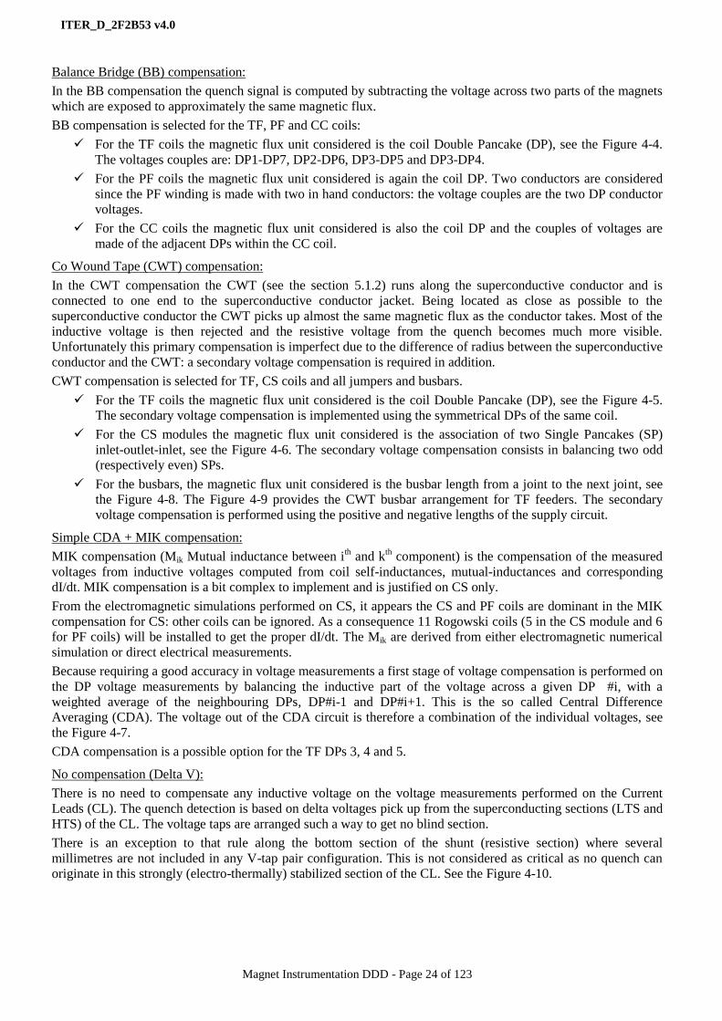
Balance Bridge (BB) compensation:
In the BB compensation the quench signal is computed by subtracting the voltage across two parts of the magnets
which are exposed to approximately the same magnetic flux.
BB compensation is selected for the TF, PF and CC coils:
For the TF coils the magnetic flux unit considered is the coil Double Pancake (DP), see the Figure 4-4.
The voltages couples are: DP1-DP7, DP2-DP6, DP3-DP5 and DP3-DP4.
For the PF coils the magnetic flux unit considered is again the coil DP. Two conductors are considered
since the PF winding is made with two in hand conductors: the voltage couples are the two DP conductor
voltages.
For the CC coils the magnetic flux unit considered is also the coil DP and the couples of voltages are
made of the adjacent DPs within the CC coil.
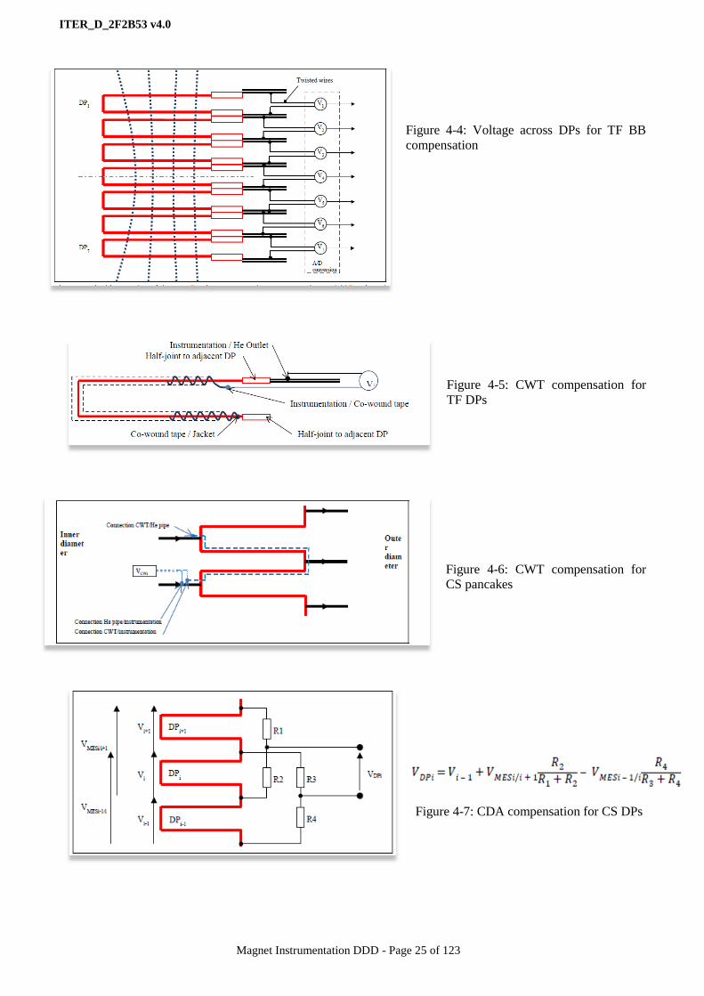
Co Wound Tape (CWT) compensation:
In the CWT compensation the CWT (see the section 5.1.2) runs along the superconductive conductor and is
connected to one end to the superconductive conductor jacket. Being located as close as possible to the
superconductive conductor the CWT picks up almost the same magnetic flux as the conductor takes. Most of the
inductive voltage is then rejected and the resistive voltage from the quench becomes much more visible.
Unfortunately this primary compensation is imperfect due to the difference of radius between the superconductive
conductor and the CWT: a secondary voltage compensation is required in addition.
CWT compensation is selected for TF, CS coils and all jumpers and busbars.
For the TF coils the magnetic flux unit considered is the coil Double Pancake (DP), see the Figure 4-5.
The secondary voltage compensation is implemented using the symmetrical DPs of the same coil.
For the CS modules the magnetic flux unit considered is the association of two Single Pancakes (SP)
inlet-outlet-inlet, see the Figure 4-6. The secondary voltage compensation consists in balancing two odd
(respectively even) SPs.
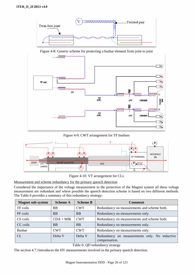
For the busbars, the magnetic flux unit considered is the busbar length from a joint to the next joint, see
the Figure 4-8. The Figure 4-9 provides the CWT busbar arrangement for TF feeders. The secondary
voltage compensation is performed using the positive and negative lengths of the supply circuit.
Simple CDA + MIK compensation:
MIK compensation (Mik Mutual inductance between ith and k
th component) is the compensation of the measured
voltages from inductive voltages computed from coil self-inductances, mutual-inductances and corresponding
dI/dt. MIK compensation is a bit complex to implement and is justified on CS only.
From the electromagnetic simulations performed on CS, it appears the CS and PF coils are dominant in the MIK
compensation for CS: other coils can be ignored. As a consequence 11 Rogowski coils (5 in the CS module and 6
for PF coils) will be installed to get the proper dI/dt. The Mik are derived from either electromagnetic numerical
simulation or direct electrical measurements.
Because requiring a good accuracy in voltage measurements a first stage of voltage compensation is performed on
the DP voltage measurements by balancing the inductive part of the voltage across a given DP #i, with a
weighted average of the neighbouring DPs, DP#i-1 and DP#i+1. This is the so called Central Difference
Averaging (CDA). The voltage out of the CDA circuit is therefore a combination of the individual voltages, see
the Figure 4-7.
CDA compensation is a possible option for the TF DPs 3, 4 and 5.
No compensation (Delta V):
There is no need to compensate any inductive voltage on the voltage measurements performed on the Current
Leads (CL). The quench detection is based on delta voltages pick up from the superconducting sections (LTS and
HTS) of the CL. The voltage taps are arranged such a way to get no blind section.
There is an exception to that rule along the bottom section of the shunt (resistive section) where several
millimetres are not included in any V-tap pair configuration. This is not considered as critical as no quench can
originate in this strongly (electro-thermally) stabilized section of the CL. See the Figure 4-10.
ITER_D_2F2B53 v4.0
Magnet Instrumentation DDD - Page 25 of 123
Figure 4-4: Voltage across DPs for TF BB
compensation
Figure 4-5: CWT compensation for
TF DPs
Figure 4-6: CWT compensation for
CS pancakes
Figure 4-7: CDA compensation for CS DPs
ITER_D_2F2B53 v4.0
Magnet Instrumentation DDD - Page 26 of 123
Figure 4-8: Generic scheme for protecting a busbar element from joint to joint
Figure 4-9: CWT arrangement for TF busbars
Figure 4-10: VT arrangement for CLs
Measurement and scheme redundancy for the primary quench detection
Considered the importance of the voltage measurement in the protection of the Magnet system all these voltage
measurement are redundant and where possible the quench detection scheme is based on two different methods.
The Table 6 provides a summary of this redundancy strategy:
Magnet sub-system Scheme A Scheme B Comment
TF coils BB CWT Redundancy on measurements and scheme both.
PF coils BB BB Redundancy on measurements only.
CS coils CDA + MIK CWT Redundancy on measurements and scheme both.
CC coils BB BB Redundancy on measurements only.
Busbar CWT CWT Redundancy on measurements only.
CL Delta V Delta V Redundancy on measurements only. No inductive
compensation.
Table 6: QD redundancy strategy
The section 4.7.1introduces the HV measurements involved in the primary quench detection.
TP
m
TP
m
HEXSHUNT (and HTS)JOINT
RT TERMINALINTERFACE
BB
T
P
5 K SHe outlet (m, T and P to interlock and data log)
50 K GHe inlet(all to data log)
300 K GHe outlet (m to interlock, all to data log)
IB
sensor
Signal (HV)
Signal (LV)
T
heater feedback loop
T-CONDITIONER T-CONTROL PLC
T set-point
FLOW-CONTROL PLC
m set-point?data log Interlock
T-control feed-back loop
T-CONDITIONER
Interlockdata log
RT Terminal temp control
T
T-CONDITIONER
T-CONTROLLER
HEATER PS
data log
Shunt voltage measurement and HTS quench detection
V-CONDITIONER & QUENCH DET MODULE
Interlockdata log
LTS LINKER
V threshold
min T set-point
HTS-CL Control & Interlock
Diagram, PB, April 27th 2012
CTB vacuum interlock
V
V
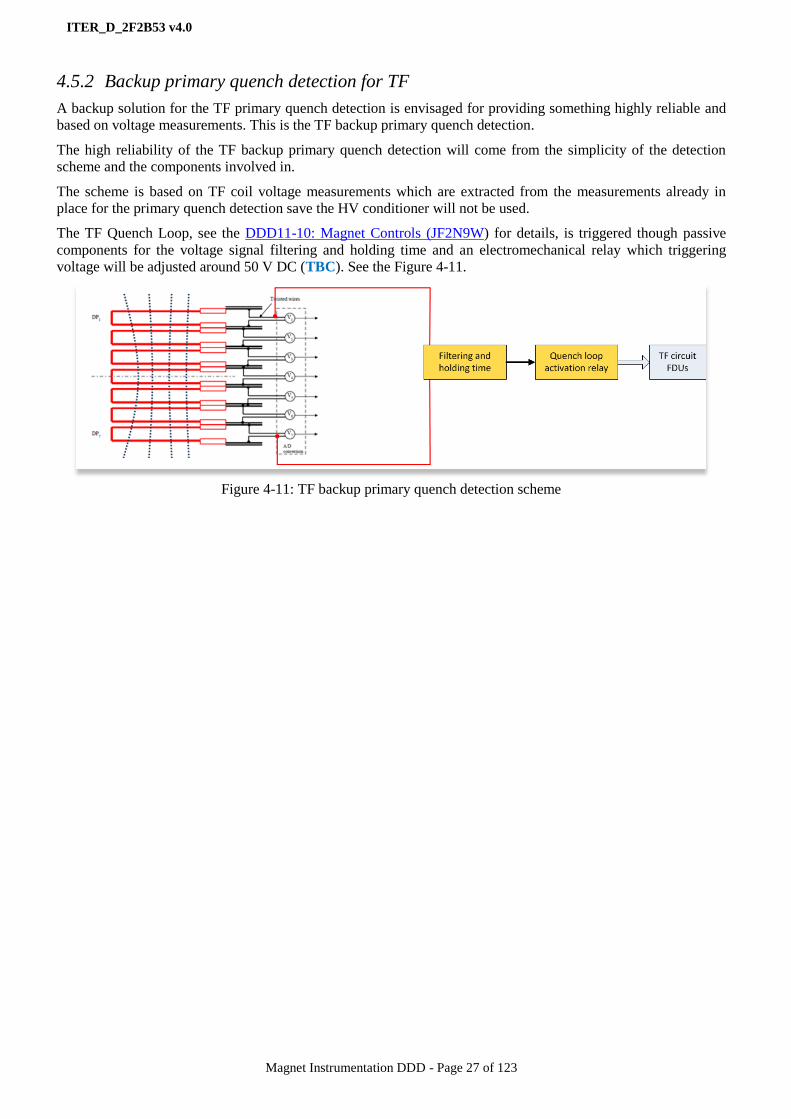
ITER_D_2F2B53 v4.0
Magnet Instrumentation DDD - Page 27 of 123
4.5.2 Backup primary quench detection for TF
A backup solution for the TF primary quench detection is envisaged for providing something highly reliable and
based on voltage measurements. This is the TF backup primary quench detection.
The high reliability of the TF backup primary quench detection will come from the simplicity of the detection
scheme and the components involved in.
The scheme is based on TF coil voltage measurements which are extracted from the measurements already in
place for the primary quench detection save the HV conditioner will not be used.
The TF Quench Loop, see the DDD11-10: Magnet Controls (JF2N9W) for details, is triggered though passive
components for the voltage signal filtering and holding time and an electromechanical relay which triggering
voltage will be adjusted around 50 V DC (TBC). See the Figure 4-11.
Figure 4-11: TF backup primary quench detection scheme
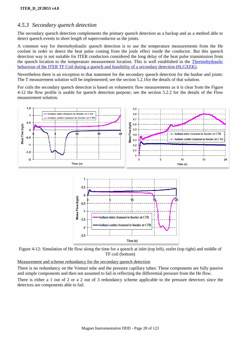
ITER_D_2F2B53 v4.0
Magnet Instrumentation DDD - Page 28 of 123
4.5.3 Secondary quench detection
The secondary quench detection complements the primary quench detection as a backup and as a method able to
detect quench events in short length of superconductor as the joints.
A common way for thermohydraulic quench detection is to use the temperature measurements from the He
coolant in order to detect the heat pulse coming from the joule effect inside the conductor. But this quench
detection way is not suitable for ITER conductors considered the long delay of the heat pulse transmission from
the quench location to the temperature measurement location. This is well established in the Thermohydraulic
behaviour of the ITER TF Coil during a quench and feasibility of a secondary detection (6LGXEK).
Nevertheless there is an exception to that statement for the secondary quench detection for the busbar and joints:
The T measurement solution will be implemented; see the section 5.2.1for the details of that solution.
For coils the secondary quench detection is based on volumetric flow measurements as it is clear from the Figure
4-12 the flow profile is usable for quench detection purpose; see the section 5.2.2 for the details of the Flow
measurement solution.
Figure 4-12: Simulation of He flow along the time for a quench at inlet (top left), outlet (top right) and middle of
TF coil (bottom)
Measurement and scheme redundancy for the secondary quench detection
There is no redundancy on the Venturi tube and the pressure capillary tubes: These components are fully passive
and simple components and then not assumed to fail in reflecting the differential pressure from the He flow.
There is either a 1 out of 2 or a 2 out of 3 redundancy scheme applicable to the pressure detectors since the
detectors are components able to fail.

ITER_D_2F2B53 v4.0
Magnet Instrumentation DDD - Page 29 of 123
4.6 Focus on thermo-mechanical behaviour monitoring of structural elements
The superconducting magnets are cooled with Supercritical Helium (SHe) at 5 K. They operate with electrical
currents of up to 70 kA and produce time-controlled varying magnetic fields peaking at 5 T in volumes of several
hundred cubic meters.
The large electro-magnetic forces to which the magnet structures are submitted lead to high stresses and
displacements. In addition to the electromagnetic loads the magnets are submitted to thermal contraction stresses
and displacements, and possible seismic events. Furthermore the ITER machine is designed to operate in a
cycling mode for 20 years, during which eventual fatigue effects and damage to the structures must be monitored.
Therefore measuring points for temperature [5 - 300 K], very small displacement (< 0.1 mm), long range multi
mm displacements, and strains (up to 10’000 micro-strain) are considered necessary to monitor the behaviour of
the magnet structures throughout the lifetime of the ITER machine. The primary target of the thermo-mechanical
instrumentation is to verify the design is under the various loads.
The secondary target is to monitor the behaviour of the structure during the life-time of the machine and reveal
eventual fatigue effects under cyclic loading. Measurements will be quasi static, with little or no constraint on the
data acquisition sampling rate. The necessary functional information concerning the thermo-mechanical
instrumentation to be installed on the TF, CS, CC and PF coil mechanical structures are given in the following
documents:
Mechanical instrumentation of the TF, CS, CC, PF coil structures (2LHDXW)
Functional requirements of the thermo-mechanical instrumentation on TF coil structures (Q8ZZ3C)
DR No. 10: CS Structure Instrumentation Changes (PTJJE8)
Instrumentation sensors are installed on the magnet structures in locations of highest physical value to be
expected from FEM simulations and analysis. The values of the structures’ strains, displacements and
temperatures will be acquired and checked at regular intervals, and no interlocking of the tokamak systems based
on signals from sensors is foreseen. Furthermore, redundancy is not a mandatory requirement, as magnets are not
part of the Safety Important Class (SIC) and there is no Magnet protection function implemented using these
sensors. Despite this the physical layout and the technologies selected for this thermos-mechanical
instrumentation are chosen so that some partial redundancy subsists in case of sensor failure:
Sensors locations respect the magnets’ periodic repeatability: if a sensor fails on a magnet structure, the
generic information is available from other identical periods
Sensors are selected among already well proven technologies given the environmental conditions such as
resistive (about 20% of all measuring points) with new emerging techniques essentially relying on optical
methods, these having the advantage of being totally immune to Electro-Magnetic Interferences (EMI)
(about 80% of all measuring points) and of connecting several sensors (up to 4) on the same fiber optic
loop.

ITER_D_2F2B53 v4.0
Magnet Instrumentation DDD - Page 30 of 123
4.7 Design options for the instrumentation chains and component family
identification
From the workflow picture of the Figure 4-1, sensors and actuators are identified in P&IDs as functional
components. These functional components are practically implemented by a number of physical components: for
dealing with component procurement and integration, all these physical components shall be identified and
specified separately.
The concept of measurement chain is used to proceed to the physical component identification. The measurement
chain starts up from the sensor element including the sensor support and ends up to the signal conditioner device.
The signal conditioner is interfaced to a Magnet controller; the details on this interface are provided in the
DDD11-10: Magnet Controls (JF2N9W).
The chain performance requirements are elaborated in the chapter 5.
4.7.1 HV chains - Voltage measurements
The model of the HV voltage measurement chain selected for ITER Magnets is shown in the Figure 4-13.
The option is to collect the signals from voltages taps using wires running into the insulating materials up to the
point these wires can be merged into vacuum cables. The vacuum cables are running into the cryostat and feeders
crossing the vacuum barrier without any cable break for connecting the HV feedthroughs of the instrumentation
feeder satellites. Then an air cable connects the HV feedthrough to the HV signal conditioners.
The signal to be transported by the wires and cables from the sensors is around 100 mA with a frequency in the
range of [0 - 1 kHz]. The HV conditioner converts the HV signals to data optically transmitted to the Magnet
control system. The HV conditioners are installed in cubicles close to the feeders for not exporting too far away
the HV signals.
This chain model introduces the following families of components:
The HV connectors for implementing the Voltage Taps (VT)
The Co Wound Tape (CWT)
The HV wires for connecting the VTs and CWTs.
The HV wire ground shields and jacket.
The HV splicing devices for connection the HV wires to HV cables.
The HV vacuum cables.
The HV plugs for crossing the Vacuum Barrier (VB)
The HV feedthrough for crossing the feeder wall.
The HV air cables.
The HV signal conditioners and optical fibre cables.
Figure 4-13: Chain model of HV voltage measurements
Over current chain protection
Over current in wires and cables of the HV chain may severely damage the components of the chain. Over current
would be the result of a double ground fault on any component of the HV chain. Ground faults are understood as
the result of a direct contact or a Paschen discharge to the ground.
For protecting the HV wires and HV cables against over current, it was considered to introduce resistors and/or
HV fuses into the HV signal paths. The resistors would be located at the level of the voltage taps for limiting the

ITER_D_2F2B53 v4.0
Magnet Instrumentation DDD - Page 31 of 123
short current while the fuses would be located at the closest of the voltage taps but in an accessible area for being
replaced.
Both options have been discarded for feasibility issue, access issue and impact on the QD reliability and accuracy.
This decision is acted in the previous version of this document: DDD11-9: Instrumentation (2F2B53 v3.0).
4.7.2 HV chains – CL heaters
The model of the CL terminal heater selected for ITER Magnets is shown in the Figure 4-14.
The baseline design is to electrically insulate the heater element from the HV voltage of the CL terminal,
basically for not exporting the HV signals too far away from the CL terminals. The heater element is electrically
connected to terminal blocks for being easily replaced for maintenance. The terminal blocks are connected by LV
cables to a power and control unit. The power and control unit is powered by the standard ITER main supply and
is interfaced to the Magnet control system through a standard data link; they installed in cubicles located in the
B74 building. The heating power per CL terminal is in the range of [1- 3 kW].
Whatever the option these models introduce the following families of components:
The heater elements (cartridges)
The heater terminal blocks.
The heater power units.
Figure 4-14: Chain model of the HV CL heaters
4.7.3 HV chains – HV T sensor
The model of the CL HV T sensor selected for ITER Magnets is shown in the Figure 4-14.
The option is to get the T sensors element installed within the warm end of the HTSCL element without any
strong voltage insulation to get a good thermal contact with the T sensor element.
The T sensor element is a Resistance Temperature Detector (RTD) technology. The T sensor is connected with
twisted wires to a CL feedthrough for crossing the CL internal vacuum/air interface. Another set of twisted wires
connects the feedthrough on the air side to the HV cable splicing device (SD).
The HV cable completes the signal path up to a HV T conditioner; the HV T conditioner converts the HV T
sensor signals to T data optically transmitted to the Magnet control system. The HV T conditioners are installed in
cubicles close to the feeders for not exporting too far away the HV T sensor signals.
Figure 4-15: Chain model of the HV T sensors

ITER_D_2F2B53 v4.0
Magnet Instrumentation DDD - Page 32 of 123
4.7.4 LV and optical chains – temperature, strain and displacement
The ITER Magnet model of LV measurement chains is shown in the Figure 4-16. This model is applicable to the
electrical LV and optical instrumentation. The selection of the proper technology and the performance
requirements for each component are elaborated in the chapter 5. The electric and optical signals shall be
conditioned for being interfaced to the Magnet control system. This chain model introduces the following families
of components:
The temperature sensors, supports and attached cables.
The displacement sensors, supports and attached cables.
The strain gages, supports and attached cables.
The patch panels (electrical and optical) for collecting locally the sensor signals.
The trunk/bundle cables (vacuum and air, electrical and optical) for connecting the signals of one patch-
panel (and only one).
The cold feedthroughs (electrical and optical) to enable the trunk/bundle cables to cross the VB.
The RT feedthroughs (electrical and optical) same purpose but for the CTB wall.
The signal conditioners for interfacing the Magnet control system. The LV signal conditioners are located
in B74 cubicles for not being exposed to the B11 building environmental constraints.
Figure 4-16: Chain model of the LV and optical measurements
4.7.5 LV chains – pressure and flow
The ITER Magnet model of pressure and flow measurement chain is shown in the Figure 4-17. The basic
principle for flow measurement is to get differential pressures from Venturi tubes introduced in the SHe flow.
These differential pressures are transmitted by capillary tubes to pressure transducers or switches located on the
air side of the feeders. The feeder wall is crossed through a capillary tube feedthrough. The pressure transducers
and switches are pneumatic/electric signal converters. The transducer signals are low level and shall be
conditioned for being interfaced to the Magnet control system; the switches signals are high level signals. This
chain model introduces the following families of components:
The Venturi tubes, pressure taps and capillary tubes.
The capillary feedthroughs.
The pressure transducers, switches and attached cables.
The patch panels for collecting locally the sensor signals. SIC (for pressure switches) and non-SIC signals
are segregated in different patch panels.
The trunk cables for transporting the patch panel signals to the signal conditioners.
The pressure signal conditioners for interfacing the Magnet control system (transducers only). They are
located in B74 cubicles for not being exposed to the B11 building environmental constraints.
Figure 4-17: Chain model of the pressure and flow measurements

ITER_D_2F2B53 v4.0
Magnet Instrumentation DDD - Page 33 of 123
4.7.6 LV chains – position switch
The control valves, burst discs, pressure relief valves and quench valves are equipped with position switches for
monitoring the valve position state (open/close) and the burst disc state (broken/intact). As a general rule, these
position switches will be procured and delivered as part of the valves and discs and will be considered in this
document for signal interface only; therefore the position switches are not represented in the Magnet P&IDs but
the valves and discs are.
The position state signal is digital and does not require any signal conditioning device. Only a patch panel is
required for collecting these signals in trunk cables prior to the control system connection. See the Figure 4-18.
This chain model introduces one family of component: The patch panels for collecting locally the position switch
signals. SIC and non-SIC are segregated in different patch panels.
Figure 4-18: Model of state position chain – They are not represented in P&IDs
4.7.7 LV chains – Rogowski coils
Rogowski coils are required to get the dI/dt for implementing the MIK quench detection scheme on CS. The
details of the suitable measurement chain model are still TBD.
4.7.8 LV chains – control valves
The control valves installed in CTBs are proportional valves pneumatically actuated but electrically controlled.
As for the position switches it is assumed the valve position sensors and the pre-actuators if any are procured and
delivered as part of the valves. In addition, the valve proportional control requires a positioner device; this device
will be integrated in B74 cubicles for not being exposed to the B11 building environmental constraints as for the
sensor signal conditioners. See the Figure 4-19.
This chain model introduces the following families of components:
The patch panels for collecting locally the valve control and state monitoring signals. SIC and non-SIC
are segregated in different patch panels.
The valve positioners.
Figure 4-19: Model of control valve control chain
4.7.9 Voltage insulating breaks
For convenience the Insulating Breaks (IB) installed on the He pipes for voltage to the
ground insulation purpose have been pushed into the instrumentation component scope and
then are addressed in this document.
IBs are passive components and therefore are not signal consumers or providers: there is no
signal chain attached to the IBs.
Figure 4-20: Symbol
of Insulating break
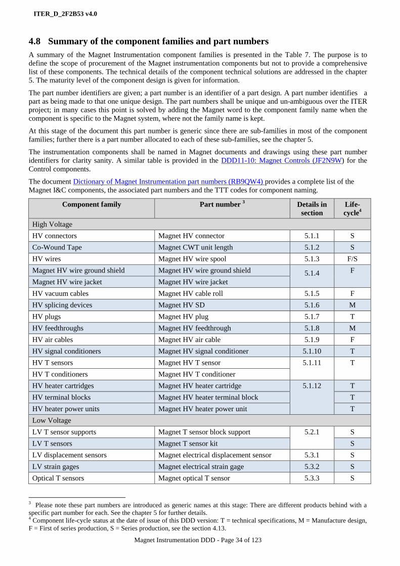
ITER_D_2F2B53 v4.0
Magnet Instrumentation DDD - Page 34 of 123
4.8 Summary of the component families and part numbers
A summary of the Magnet Instrumentation component families is presented in the Table 7. The purpose is to
define the scope of procurement of the Magnet instrumentation components but not to provide a comprehensive
list of these components. The technical details of the component technical solutions are addressed in the chapter
5. The maturity level of the component design is given for information.
The part number identifiers are given; a part number is an identifier of a part design. A part number identifies a
part as being made to that one unique design. The part numbers shall be unique and un-ambiguous over the ITER
project; in many cases this point is solved by adding the Magnet word to the component family name when the
component is specific to the Magnet system, where not the family name is kept.
At this stage of the document this part number is generic since there are sub-families in most of the component
families; further there is a part number allocated to each of these sub-families, see the chapter 5.
The instrumentation components shall be named in Magnet documents and drawings using these part number
identifiers for clarity sanity. A similar table is provided in the DDD11-10: Magnet Controls (JF2N9W) for the
Control components.
The document Dictionary of Magnet Instrumentation part numbers (RB9QW4) provides a complete list of the
Magnet I&C components, the associated part numbers and the TTT codes for component naming.
Component family Part number 3 Details in
section
Life-
cycle4
High Voltage
HV connectors Magnet HV connector 5.1.1 S
Co-Wound Tape Magnet CWT unit length 5.1.2 S
HV wires Magnet HV wire spool 5.1.3 F/S
Magnet HV wire ground shield Magnet HV wire ground shield 5.1.4 F
Magnet HV wire jacket Magnet HV wire jacket
HV vacuum cables Magnet HV cable roll 5.1.5 F
HV splicing devices Magnet HV SD 5.1.6 M
HV plugs Magnet HV plug 5.1.7 T
HV feedthroughs Magnet HV feedthrough 5.1.8 M
HV air cables Magnet HV air cable 5.1.9 F
HV signal conditioners Magnet HV signal conditioner 5.1.10 T
HV T sensors Magnet HV T sensor 5.1.11 T
HV T conditioners Magnet HV T conditioner
HV heater cartridges Magnet HV heater cartridge 5.1.12 T
HV terminal blocks Magnet HV heater terminal block T
HV heater power units Magnet HV heater power unit T
Low Voltage
LV T sensor supports Magnet T sensor block support 5.2.1 S
LV T sensors Magnet T sensor kit S
LV displacement sensors Magnet electrical displacement sensor 5.3.1 S
LV strain gages Magnet electrical strain gage 5.3.2 S
Optical T sensors Magnet optical T sensor 5.3.3 S
3 Please note these part numbers are introduced as generic names at this stage: There are different products behind with a
specific part number for each. See the chapter 5 for further details. 4 Component life-cycle status at the date of issue of this DDD version: T = technical specifications, M = Manufacture design,
F = First of series production, S = Series production, see the section 4.13.
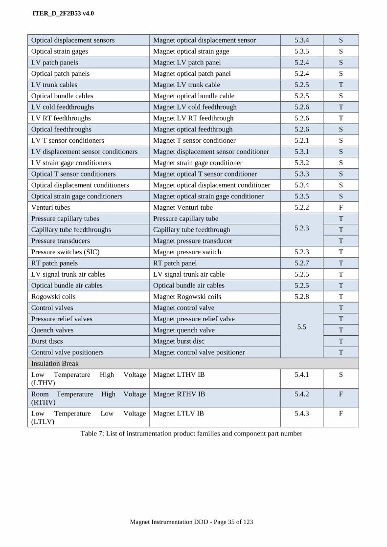
ITER_D_2F2B53 v4.0
Magnet Instrumentation DDD - Page 35 of 123
Optical displacement sensors Magnet optical displacement sensor 5.3.4 S
Optical strain gages Magnet optical strain gage 5.3.5 S
LV patch panels Magnet LV patch panel 5.2.4 S
Optical patch panels Magnet optical patch panel 5.2.4 S
LV trunk cables Magnet LV trunk cable 5.2.5 T
Optical bundle cables Magnet optical bundle cable 5.2.5 S
LV cold feedthroughs Magnet LV cold feedthrough 5.2.6 T
LV RT feedthroughs Magnet LV RT feedthrough 5.2.6 T
Optical feedthroughs Magnet optical feedthrough 5.2.6 S
LV T sensor conditioners Magnet T sensor conditioner 5.2.1 S
LV displacement sensor conditioners Magnet displacement sensor conditioner 5.3.1 S
LV strain gage conditioners Magnet strain gage conditioner 5.3.2 S
Optical T sensor conditioners Magnet optical T sensor conditioner 5.3.3 S
Optical displacement conditioners Magnet optical displacement conditioner 5.3.4 S
Optical strain gage conditioners Magnet optical strain gage conditioner 5.3.5 S
Venturi tubes Magnet Venturi tube 5.2.2 F
Pressure capillary tubes Pressure capillary tube
5.2.3
T
Capillary tube feedthroughs Capillary tube feedthrough T
Pressure transducers Magnet pressure transducer T
Pressure switches (SIC) Magnet pressure switch 5.2.3 T
RT patch panels RT patch panel 5.2.7 T
LV signal trunk air cables LV signal trunk air cable 5.2.5 T
Optical bundle air cables Optical bundle air cables 5.2.5 T
Rogowski coils Magnet Rogowski coils 5.2.8 T
Control valves Magnet control valve
5.5
T
Pressure relief valves Magnet pressure relief valve T
Quench valves Magnet quench valve T
Burst discs Magnet burst disc T
Control valve positioners Magnet control valve positioner T
Insulation Break
Low Temperature High Voltage
(LTHV)
Magnet LTHV IB 5.4.1 S
Room Temperature High Voltage
(RTHV)
Magnet RTHV IB 5.4.2 F
Low Temperature Low Voltage
(LTLV)
Magnet LTLV IB 5.4.3 F
Table 7: List of instrumentation product families and component part number

ITER_D_2F2B53 v4.0
Magnet Instrumentation DDD - Page 36 of 123
4.9 Grounding scheme and EMC
The Magnet system grounding scheme overview and the main principles to apply are given in the following
document: Magnet Grounding scheme status (QV49XG) . This section focuses on the Magnet I&C component
grounding scheme only.
The ITER requirements for grounding and EMC as specified in [RD5] apply. They are implemented the following
ways for HV and LV instrumentation components:
4.9.1 HV signals
The applicable scheme for HV signals is shown in the Figure 4-21:
Any Magnet superconductive component is protected by a ground plane for suppressing the risk coming
from the local accumulation of electrostatic charges.
This ground plane is connected to the Magnet ground on a single point.
The HV signal wires are running in the component voltage insulation system from the voltage taps up to
the HV splicing device location. The HV wires are gathered in cables of twisted pairs, triplets,
quadruplets or quintuplets depending on the applicable HV signal routing scheme.
Where not protected by the ground plane the HV wires are equipped with a wire ground shield and an
overall twisted wire ground shield and insulated jacket.
The HV Splicing Device (SD) connects the HV wires to the HV cable wires. This SD is equipped with a
ground shield connected to the HV wire and HV cable ground shields. This configuration complies with
the single earthing scheme in use within the cryostat.
The HV cable is made of twisted wires and is connected to the HV feedthrough at the other end. The
cable ground shield is connected to the HV feedthrough ground shield.
The HV feedthrough ground shield is connected to the feeder wall. The feeder wall is connected to the
ITER Common Bonding Network (CBN)
On the HV feedthrough air side, the HV air cable connects the HV feedthrough to the HV signal
conditioners. The HV air cable ground shield is connected at both ends: HV feedthrough and HV cubicle
enclosure.
The HV cubicle enclosure is connected to the CBN.
Figure 4-21: Grounding scheme for HV signals, single wire ground shield and HV shield not represented.
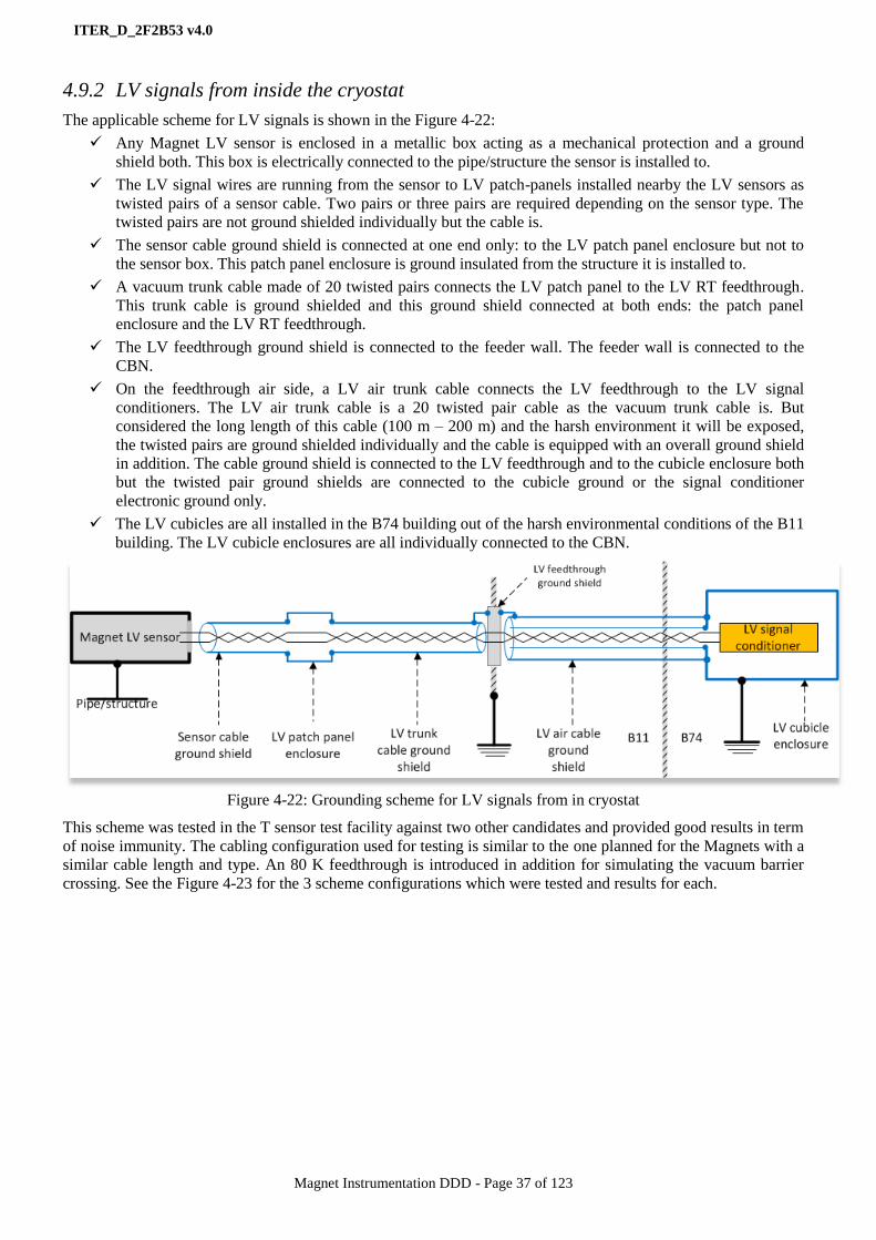
ITER_D_2F2B53 v4.0
Magnet Instrumentation DDD - Page 37 of 123
4.9.2 LV signals from inside the cryostat
The applicable scheme for LV signals is shown in the Figure 4-22:
Any Magnet LV sensor is enclosed in a metallic box acting as a mechanical protection and a ground
shield both. This box is electrically connected to the pipe/structure the sensor is installed to.
The LV signal wires are running from the sensor to LV patch-panels installed nearby the LV sensors as
twisted pairs of a sensor cable. Two pairs or three pairs are required depending on the sensor type. The
twisted pairs are not ground shielded individually but the cable is.
The sensor cable ground shield is connected at one end only: to the LV patch panel enclosure but not to
the sensor box. This patch panel enclosure is ground insulated from the structure it is installed to.
A vacuum trunk cable made of 20 twisted pairs connects the LV patch panel to the LV RT feedthrough.
This trunk cable is ground shielded and this ground shield connected at both ends: the patch panel
enclosure and the LV RT feedthrough.
The LV feedthrough ground shield is connected to the feeder wall. The feeder wall is connected to the
CBN.
On the feedthrough air side, a LV air trunk cable connects the LV feedthrough to the LV signal
conditioners. The LV air trunk cable is a 20 twisted pair cable as the vacuum trunk cable is. But
considered the long length of this cable (100 m – 200 m) and the harsh environment it will be exposed,
the twisted pairs are ground shielded individually and the cable is equipped with an overall ground shield
in addition. The cable ground shield is connected to the LV feedthrough and to the cubicle enclosure both
but the twisted pair ground shields are connected to the cubicle ground or the signal conditioner
electronic ground only.
The LV cubicles are all installed in the B74 building out of the harsh environmental conditions of the B11
building. The LV cubicle enclosures are all individually connected to the CBN.
Figure 4-22: Grounding scheme for LV signals from in cryostat
This scheme was tested in the T sensor test facility against two other candidates and provided good results in term
of noise immunity. The cabling configuration used for testing is similar to the one planned for the Magnets with a
similar cable length and type. An 80 K feedthrough is introduced in addition for simulating the vacuum barrier
crossing. See the Figure 4-23 for the 3 scheme configurations which were tested and results for each.
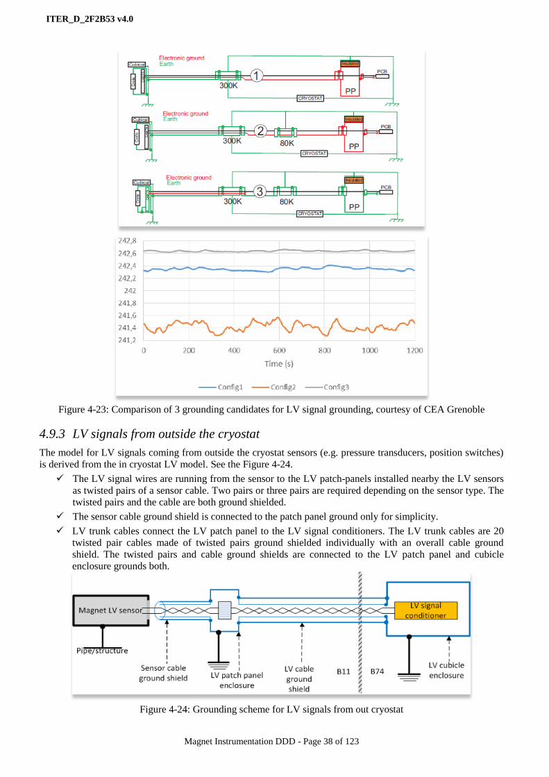
ITER_D_2F2B53 v4.0
Magnet Instrumentation DDD - Page 38 of 123
Figure 4-23: Comparison of 3 grounding candidates for LV signal grounding, courtesy of CEA Grenoble
4.9.3 LV signals from outside the cryostat
The model for LV signals coming from outside the cryostat sensors (e.g. pressure transducers, position switches)
is derived from the in cryostat LV model. See the Figure 4-24.
The LV signal wires are running from the sensor to the LV patch-panels installed nearby the LV sensors
as twisted pairs of a sensor cable. Two pairs or three pairs are required depending on the sensor type. The
twisted pairs and the cable are both ground shielded.
The sensor cable ground shield is connected to the patch panel ground only for simplicity.
LV trunk cables connect the LV patch panel to the LV signal conditioners. The LV trunk cables are 20
twisted pair cables made of twisted pairs ground shielded individually with an overall cable ground
shield. The twisted pairs and cable ground shields are connected to the LV patch panel and cubicle
enclosure grounds both.
Figure 4-24: Grounding scheme for LV signals from out cryostat

ITER_D_2F2B53 v4.0
Magnet Instrumentation DDD - Page 39 of 123
4.10 Measurement calibration strategy
The signal flow model starts-up at the signal producer level (the sensor); the sensor signal is then transmitted as a
raw analogue signal for being conditioned to get a standard range signal. Sometimes this signal conditioning is
performed by some built-in electronics (e.g. pressure transmitters); if not a specific signal conditioning device is
required.
The signal is then converted into raw data by the controller signal interface ADC or the signal conditioner ADC.
Finally the raw data is converted into engineering data by a Magnet controller or the signal conditioner. See an
illustration of this signal flow in the Figure 4-25.
Figure 4-25: Picture of the signal flow model
The measurement calibration model applicable to the Magnet system targets all components of the measurement
chain and the measurement chain life-cycle:
Calibration at installation phase:
The signal producer (the sensor) shall be calibrated and the calibration factors plus the procedure for re-
calibration shall be provided by the sensor supplier.
The signal conditioner shall be calibrated and the calibration procedure shall be provided by the
conditioner supplier.
The signal interface ADC shall be calibrated and the calibration procedure shall be provided by the signal
interface supplier.
The engineering data conversion shall be performed against the calibration factors provided by the signal
producer supplier. For this purpose a library of signal treatments will be developed by the control system
software supplier such a way the calibration factors will be used as configuration data by the CODAC
system. See the definition of the configuration data in the CODAC system user manuals.
Re-calibration at operation phase:
The calibration of the Magnet system measurement chains will be performed during the Long Term
Maintenance (LTM) when the Magnet system is in safe state.
The non-accessible sensors as temperature, displacement and strain gauges will not be considered for re-
calibration. Only the accessible sensors will be (pressure transducers basically)
For simplification and resource saving purpose, the signal conditioners and the signal interface ADC will
be tested against linearity and range both as a fully integrated component (not individually) and will be
recalibrated either at conditioner or signal interface side depending on the test results.
As a first approach, the raw data / engineering data conversion will not be modified along the life span of
the sensor. An exception for non-accessible sensors may be considered in case the sensor can be re-
calibrated (e.g. through indirect measurements).
Signal
conditioner
Signal
producer
Signal
interface
ADC
Engineering
data
conversion
Raw signalStandard
signal Raw data
Engineering
data
Data
consumers
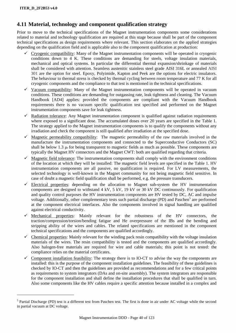
ITER_D_2F2B53 v4.0
Magnet Instrumentation DDD - Page 40 of 123
4.11 Material, technology and component qualification strategy
Prior to move to the technical specifications of the Magnet instrumentation components some considerations
related to material and technology qualification are required at this stage because shall be part of the component
technical specifications as design requirements where relevant. This section elaborates on the applied strategies
depending on the qualification field and is applicable also to the component qualification at production:
Cryogenic compatibility: Many of the Magnet instrumentation components will be operated in cryogenic
conditions down to 4 K. These conditions are demanding for steels, voltage insulation materials,
mechanical and optical systems. In particular the differential thermal expansion/shrinkage of materials
shall be considered with attention. Seamless austenitic stainless steel grade AISI 316L or annealed AISI
301 are the option for steel. Epoxy, Polyimide, Kapton and Peek are the options for electric insulators.
The behaviour to thermal stress is checked by thermal cycling between room temperature and 77 K for all
cryogenic components and the compliance to that test is mentioned in the technical specifications.
Vacuum compatibility: Many of the Magnet instrumentation components will be operated in vacuum
conditions. These conditions are demanding for outgassing rate, leak tightness and cleaning. The Vacuum
Handbook [AD4] applies: provided the components are compliant with the Vacuum Handbook
requirements there is no vacuum specific qualification test specified and performed on the Magnet
instrumentation components save for leak tightness.
Radiation tolerance: Any Magnet instrumentation component is qualified against radiation requirements
where exposed to a significant dose. The accumulated doses over 20 years are specified in the Table 1.
The strategy applied to the Magnet instrumentation components is to qualify the components without any
irradiation and check the component is still qualified after irradiation at the specified dose.
Magnetic permeability compatibility: The magnetic permeability of the raw materials involved in the
manufacture the instrumentation components and connected to the Superconductive Conductors (SC)
shall be below 1.3 μr for being transparent to magnetic fields as much as possible. These components are
typically the Magnet HV connectors and the Magnet CWT: both are qualified regarding that criteria.
Magnetic field tolerance: The instrumentation components shall comply with the environment conditions
of the location at which they will be installed: The magnetic field levels are specified in the Table 1. HV
instrumentation components are all passive, no qualification is required. For LV measurements, the
selected technology is well-known in the Magnet community for not being magnetic field sensitive. In
case of doubt a magnetic field qualification shall be performed, e.g. the pressure transducers.
Electrical properties: depending on the allocation to Magnet sub-system the HV instrumentation
components are designed to withstand 4 kV, 5 kV, 19 kV or 30 kV DC continuously. For qualification
and quality control purposes the HV instrumentation components are HV tested by DC, AC and impulse
voltage. Additionally, other complementary tests such partial discharge (PD) and Paschen5 are performed
at the component electrical interfaces. Also the components involved in signal handling are qualified
against electrical conductivity.
Mechanical properties: Mainly relevant for the robustness of the HV connectors, the
traction/compression/torsion/bending fatigue and He overpressure of the IBs and the bending and
stripping ability of the wires and cables. The related specifications are mentioned in the component
technical specifications and the components are qualified accordingly.
Chemical properties: Mainly relevant for the winding pack resin compatibility with the voltage insulation
materials of the wires. The resin compatibility is tested and the components are qualified accordingly.
Also halogen-free materials are required for wire and cable materials; this point is not tested: the
compliance relies on the material certificates.
Component installation feasibility: The strategy there is to IO-CT to advise the way the components are
installed: this is the purpose of the component installation guidelines. The feasibility of these guidelines is
checked by IO-CT and then the guidelines are provided as recommendations and for a few critical points
as requirements to system integrators (DAs and on-site assembly). The system integrators are responsible
for the component installation and shall define the installation procedures that shall be qualified in turn.
Also some components like the HV cables require a specific attention because installed in a complex and
5 Partial Discharge (PD) test is a different test from Paschen test. The first is done in air under AC voltage while the second
in partial vacuum at DC voltage.
ITER_D_2F2B53 v4.0
Magnet Instrumentation DDD - Page 41 of 123
difficult to access environment: In such a case the installation procedure is qualified in a test facility set
up on purpose.
More details about these requirements are given in the component technical specifications in the chapter 5 and
how they are implemented in the chapters 6 and 7.
4.12 Procurement strategy
The Magnet instrumentation components being identified see the Table 7 and specified see the chapter 5, the next
step is to define the procurement strategy, basically answer the question: who will procure what and how?
The “What” is determined by the part number list of the Table 7; the “Who” is driven by the ITER PA sharing
and the “How” is determined from some integration and technology considerations (for the procurements
performed by IO-CT only)
For mitigating the integration issues the option is to procure complete measurement chains instead of separate
components from separate contracts where possible (typically for the case LV measurements but not for HV
measurements which are far too much specific).
For the components which are part of the HV measurement chains and since the IO-CT strategy is to drive the
design and procurement, the design workflow starts-up at the HV connector and CWT components and ends-up at
the control system interface. Wires and cables are designed first; connecting devices (HV connectors, plugs, and
feedthroughs) are coming after; then the HV conditioners.
For cost optimisation purpose the option is to gather together different components of same technology and
procure all of them through a single and same contract.
As a consequence the Magnet Instrumentation component strategy is as shown in the Table 8 below:
What: part number Who How
High Voltage
Magnet HV connectors IO-CT Direct and dedicated contract placed by IO-CT
Magnet CWT unit lengths IO-CT Direct and dedicated contract placed by IO-CT
Magnet HV wire spools IO-CT Direct and dedicated contract placed by IO-CT
Magnet HV wire ground shield IO-CT
Magnet HV wire jacket
Magnet HV SDs IO-CT Direct and dedicated contract placed by IO-CT
Magnet HV cable rolls
Magnet HV plugs IO-CT Direct and dedicated contract placed by IO-CT
Magnet HV feedthroughs IO-CT Direct and dedicated contract placed by IO-CT
Magnet HV air cables IO-CT Standard ITER cables selected from the ITER
catalogue and provided through an IO-CT
framework contract.
Magnet HV signal conditioners IO-CT Direct and dedicated contract placed by IO-CT
Magnet HV signal optical fibres
Magnet HV T sensors IO-CT Direct and dedicated contract placed by IO-CT
Magnet HV T conditioners Merged with the HV signal conditioner contract
Magnet HV heater cartridges IO-CT Direct and dedicated contract placed by IO-CT.
Scope is the heating chain, all included save the HV
air cables Magnet HV heater terminal blocks
Magnet HV heater power units

ITER_D_2F2B53 v4.0
Magnet Instrumentation DDD - Page 42 of 123
Low Voltage
Magnet T sensor block support IO-CT Direct and dedicated contract placed by IO-CT.
Scope is the T sensor chain. The contract scope
includes the RT feedthroughs. Magnet T sensor kit
Magnet T sensor conditioner
Magnet displacement sensor IO-CT Direct and dedicated contract placed by IO-CT.
Scope is the T sensor chain. The contract scope
includes the RT feedthroughs. Magnet strain gage
Magnet electrical displacement sensor
conditioner
Magnet LV strain gage conditioner
Magnet optical T sensor IO-CT Direct and dedicated contract placed by IO-CT.
Scope is the T sensor chain. The contract scope
includes the RT feedthroughs. Magnet optical displacement sensor
Magnet optical strain gage
Magnet optical feedthrough
Magnet optical T sensor conditioner
Magnet optical displacement conditioner
Magnet optical strain gage conditioner
Magnet LV patch panel IO-CT Direct and dedicated contract placed by IO-CT
Magnet optical patch panel
Magnet LV trunk cold cable IO-CT Standard ITER cables selected from the ITER
catalogue and provided through an IO-CT
framework contract. Magnet optical bundle cable
Magnet LV cold feedthrough IO-CT Direct and dedicated contract placed by IO-CT
Magnet LV RT feedthrough IO-CT These feedthroughs are included in the scope of
delivery of the LV measurement contracts
Magnet Venturi tube IO-CT Direct and dedicated contract placed by IO-CT
Pressure capillary tube
Capillary tube feedthrough CNDA Are part of the CNDA feeder PA delivery
Magnet pressure transducer IO-CT Direct and dedicated contract placed by IO-CT
Magnet pressure switch
RT patch panel IO-CT Standard ITER products selected from the ITER
catalogue and provided through an IO-CT
framework contract LV signal trunk air cable
Optical bundle air cable
Magnet control valve CNDA Are part of the CNDA feeder PA delivery but are
specified by IO-CT Magnet pressure relief valve
Magnet quench valve
Magnet burst disc
Magnet control valve positioner
Rogowski coils IO-CT Still TBD
Others
Magnet LTHV IB IO-CT Direct and dedicated contract placed by IO-CT
Magnet RTHV IB IO-CT Direct and dedicated contract placed by IO-CT
Magnet LTLV IB IO-CT Direct and dedicated contract placed by IO-CT
Table 8: Instrumentation component procurement strategy

ITER_D_2F2B53 v4.0
Magnet Instrumentation DDD - Page 43 of 123
4.13 Component life-cycle
For the components identified as to be procured by IO-CT, see the Table 8, a standard
life-cycle is applied and implemented by the IO-CT Magnet division.
This standard component life-cycle is a linear sequence of phases each one formally
completed through a decision to move to next phase or to a successful test result:
a) The requirements in the top box are those mentioned in the chapter 3 and
completed by the design options of the chapter 4. The compilation of these requirements
provides a conceptual component design.
b) The R&D targets at selecting the right technology out of what is available in the
industry for mitigating any risks at qualification. The outcomes of the R&D phase
enable to refine the conceptual design to get a preliminary design. It may happen the
technology qualification drives the supplier selection; if so the potential suppliers are
identified at this level.
c) The technical specifications are the result of the compilation of the outcomes of
phases a) and b) for moving to the component call for tender. The technical
specifications are formally reviewed and approved as a final component design.
d) The call for tender is performed through a standard IO-CT procurement
procedure and is ended by the supplier selection and the contract signature. For cost
reason it could happen the call for tender fails, in such a case the requirements are kept
but the technical specifications are refined to get something acceptable in cost and
performance both.
e) The detailed design is pushed in the scope of the procurement contract. This
detailed design is formally reviewed and approved by IO-CT.
f) Then the supplier proceeds to a first of series production. This production is
qualified by IO-CT regarding performance requirements and other requirements listed
in the section 4.11. Despite the R&D work performed at the beginning of that process it
could happen to face some qualification issues. For most cases these issues have been
solved by moving on the manufacture design until the qualification was passed
successfully.
g) Whether the qualification is successful the series production is started. QA and
QC requirements apply at series production as well; see the chapter 6 for details.
Figure 4-26: Component life-cycle mode applicable to any Magnet instrumentation
component
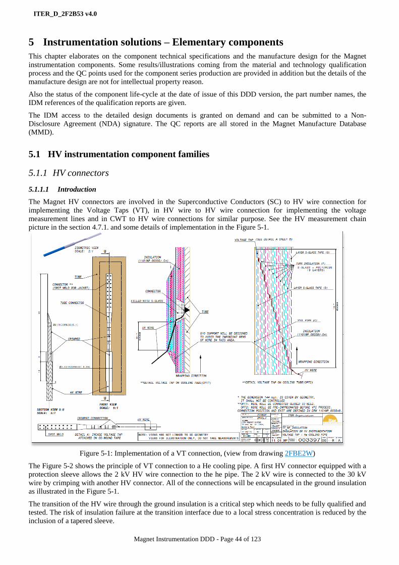
ITER_D_2F2B53 v4.0
Magnet Instrumentation DDD - Page 44 of 123
5 Instrumentation solutions – Elementary components
This chapter elaborates on the component technical specifications and the manufacture design for the Magnet
instrumentation components. Some results/illustrations coming from the material and technology qualification
process and the QC points used for the component series production are provided in addition but the details of the
manufacture design are not for intellectual property reason.
Also the status of the component life-cycle at the date of issue of this DDD version, the part number names, the
IDM references of the qualification reports are given.
The IDM access to the detailed design documents is granted on demand and can be submitted to a Non-
Disclosure Agreement (NDA) signature. The QC reports are all stored in the Magnet Manufacture Database
(MMD).
5.1 HV instrumentation component families
5.1.1 HV connectors
5.1.1.1 Introduction
The Magnet HV connectors are involved in the Superconductive Conductors (SC) to HV wire connection for
implementing the Voltage Taps (VT), in HV wire to HV wire connection for implementing the voltage
measurement lines and in CWT to HV wire connections for similar purpose. See the HV measurement chain
picture in the section 4.7.1. and some details of implementation in the Figure 5-1.
Figure 5-1: Implementation of a VT connection, (view from drawing 2FBE2W)
The Figure 5-2 shows the principle of VT connection to a He cooling pipe. A first HV connector equipped with a
protection sleeve allows the 2 kV HV wire connection to the he pipe. The 2 kV wire is connected to the 30 kV
wire by crimping with another HV connector. All of the connections will be encapsulated in the ground insulation
as illustrated in the Figure 5-1.
The transition of the HV wire through the ground insulation is a critical step which needs to be fully qualified and
tested. The risk of insulation failure at the transition interface due to a local stress concentration is reduced by the
inclusion of a tapered sleeve.
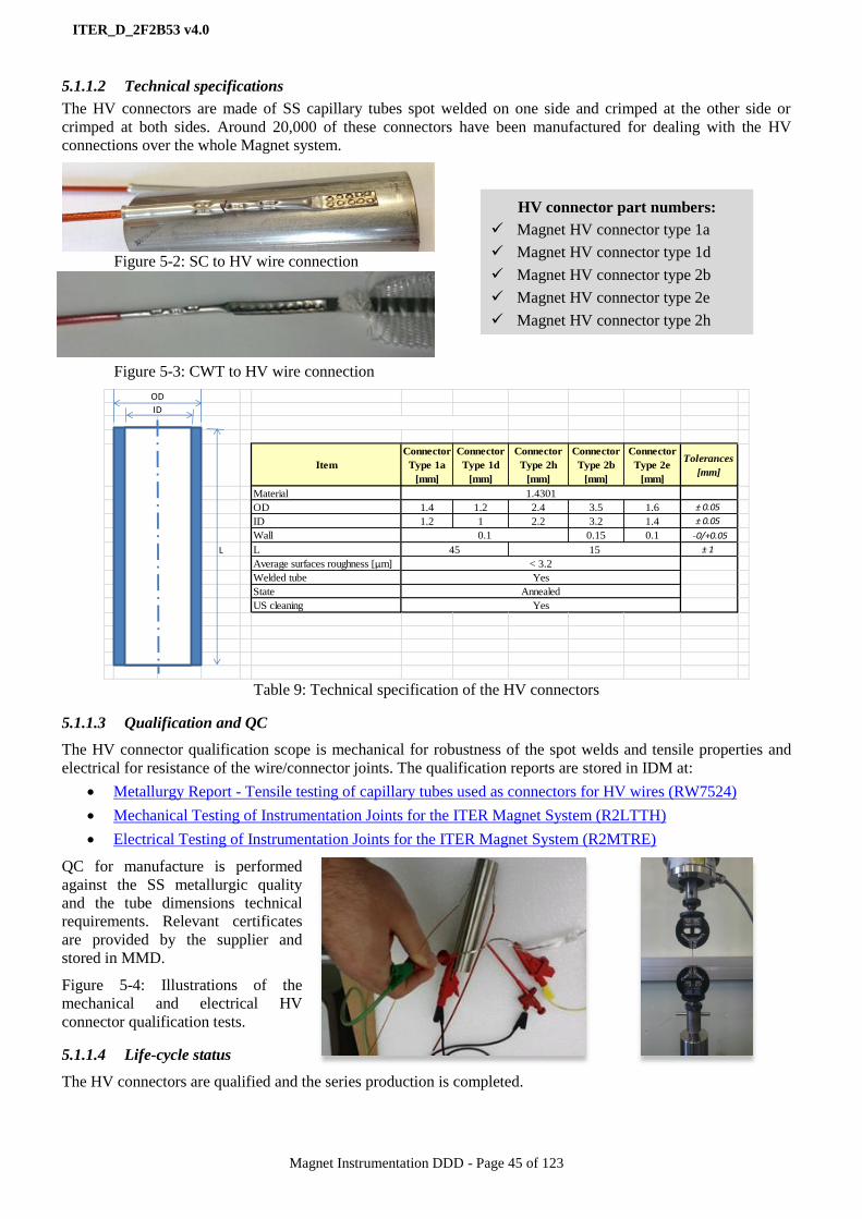
ITER_D_2F2B53 v4.0
Magnet Instrumentation DDD - Page 45 of 123
5.1.1.2 Technical specifications
The HV connectors are made of SS capillary tubes spot welded on one side and crimped at the other side or
crimped at both sides. Around 20,000 of these connectors have been manufactured for dealing with the HV
connections over the whole Magnet system.
Figure 5-2: SC to HV wire connection
Figure 5-3: CWT to HV wire connection
Table 9: Technical specification of the HV connectors
5.1.1.3 Qualification and QC
The HV connector qualification scope is mechanical for robustness of the spot welds and tensile properties and
electrical for resistance of the wire/connector joints. The qualification reports are stored in IDM at:
Metallurgy Report - Tensile testing of capillary tubes used as connectors for HV wires (RW7524)
Mechanical Testing of Instrumentation Joints for the ITER Magnet System (R2LTTH)
Electrical Testing of Instrumentation Joints for the ITER Magnet System (R2MTRE)
QC for manufacture is performed
against the SS metallurgic quality
and the tube dimensions technical
requirements. Relevant certificates
are provided by the supplier and
stored in MMD.
Figure 5-4: Illustrations of the
mechanical and electrical HV
connector qualification tests.
5.1.1.4 Life-cycle status
The HV connectors are qualified and the series production is completed.
Item
Connector
Type 1a
[mm]
Connector
Type 1d
[mm]
Connector
Type 2h
[mm]
Connector
Type 2b
[mm]
Connector
Type 2e
[mm]
Tolerances
[mm]
Material
OD 1.4 1.2 2.4 3.5 1.6 ± 0.05
ID 1.2 1 2.2 3.2 1.4 ± 0.05
Wall 0.15 0.1 -0/+0.05
L L ± 1
Average surfaces roughness [µm]
Welded tube
State
US cleaning Yes
0.1
1545
< 3.2
OD
ID
1.4301
Yes
Annealed
HV connector part numbers:
Magnet HV connector type 1a
Magnet HV connector type 1d
Magnet HV connector type 2b
Magnet HV connector type 2e
Magnet HV connector type 2h
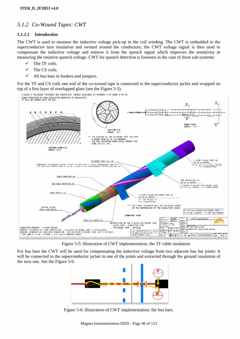
ITER_D_2F2B53 v4.0
Magnet Instrumentation DDD - Page 46 of 123
5.1.2 Co-Wound Tapes: CWT
5.1.2.1 Introduction
The CWT is used to measure the inductive voltage pick-up in the coil winding. The CWT is embedded in the
superconductor turn insulation and twisted around the conductors; the CWT voltage signal is then used to
compensate the inductive voltage and remove it from the quench signal which improves the sensitivity in
measuring the resistive quench voltage. CWT for quench detection is foreseen in the case of three sub-systems:
The TF coils.
The CS coils.
All bus bars in feeders and jumpers.
For the TF and CS coils one end of the co-wound tape is connected to the superconductor jacket and wrapped on
top of a first layer of overlapped glass (see the Figure 5-5).
Figure 5-5: Illustration of CWT implementation: the TF cable insulation
For bus bars the CWT will be used for compensating the inductive voltage from two adjacent bus bar joints: It
will be connected to the superconductor jacket in one of the joints and extracted through the ground insulation of
the next one. See the Figure 5-6.
.
Figure 5-6: Illustration of CWT implementation: the bus bars.

ITER_D_2F2B53 v4.0
Magnet Instrumentation DDD - Page 47 of 123
After studying different alternatives: a) stainless steel in polyimide sandwich, b) polyester fabric conductive tape
and c) stainless steel strips made of rounded wires embedded in fiberglass, the last option has been chosen as a
good compromise:
It is supposed to be easier to wrap up than option a because of the lower spring back. Besides its
stainless steel strip is not a potential threat to the turn insulation because of the rounded edges.
It is easier to connect (to jacket, wires and to the He pipe) and to repair than b (fabric tape). Besides it
does not need further qualification with respect to impregnation and radiation because uses stainless
steel and fiberglass are already present in the conductor and turn insulation.
5.1.2.2 Technical specifications
Two types of CWT are required, see the Table 10:
Type 1: One metal strip grade 1.4310 solution annealed and S-glass for TF coils and the Feeder bus bars.
Type 2: Two metal strips 1.4310 solution annealed and E-glass for CS coils
Item CWT Type 1 (for TF
coils and Feeders)
CWT Type 2 (for
CS coils)
Note
Steel
tape
Material Stainless Steel: 1.4310 solution annealed Ultra-Sonic cleaned
Magnetic perm. < 10 µr
Dimensions 0.05 ± 0.01 × 2.8 ± 0.1[mm]
El. resistance [kΩ]
0.6 – 0.7 (120 m)
1.8 – 2.0 (350 m)
2.1 – 2.4 (410 m)
6.0(*)+10% (550 m)
(*) Series of two strips
Notes Rounded edges
Glass
Yarn
Type of glass S-glass E-glass
Same yarn as the coil
turn insulation Yarn type 493 S-2 Glass Yarn
SCG150 (SC9 33) 1/0
Z40 (1.0Z) size 493
Tex 68×1, Silan Size
(Warp thread)
Tex 34×1, Silan Size
(Weft thread)
Yarn treatment Silan Silan
CWT
No. of steel strips 1 2
Position of the steel strip Centered ± 1 mm 3 ± 1 mm
from each border
Type of texture Plain weave Plain weave
Width [mm] 15 ± 1 50 ± 1
Mid tape thickness [mm] 0.14 +0.04 /-0.02 0.20 ± 0.03 Micrometer pressure:
5 N, area: Φ 10 mm
Warp thread 34 yarns
1 metal strip
71 yarns
2 metal strip
ISO 4602
Weft density [Yarns/cm] 8×2 ± 0.5 12×2 ± 0.5 ISO 4602
Weight [g/m2] 200+10% 225 ± 10%
Weight [g/m] 3.0±10% 11.25 ±10%
Breaking load [N] ≥ 900 ≥ 2500 ISO 4606
Table 10: Technical specification of the CWT
A total of 222,500 m and 250,000 m is required for the CWT type 1 and 2 respectively.

ITER_D_2F2B53 v4.0
Magnet Instrumentation DDD - Page 48 of 123
Figure 5-7: Illustration of CWT type 1 (left) and type 2 (right)
Figure 5-8: Illustration of CWT type 1 wrapping on a TF conductor.
5.1.2.3 Qualification and QC
The CWT qualification scope is mechanical for thickness and strength, tolerance to cryogenic and radiation
conditions and easy wrapping (absence of wrinkles and waves). See the qualification reports:
Tensile tests on Co-wound tapes - Irradiated and non-irradiated (R5THFV)
Tensile test report on SS co-wound strips at RT from CERN
Tensile test report on SS co-wound strips at 4.2 K from CERN
Mechanical testing & roughness on CWT joints from CERN
The thickness requirements and the absence of waves have been solved by playing with the CWT manufacture
procedure, the tolerance to cryogenic conditions have been met by the selection of the raw materials (e-glass, s-
glass and SS) and the easy wrapping required a dedicated R&D program before being solved by playing with the
CWT tension and twist pitch values. See an illustration of wrapping trial in the Figure 5-10.
QC at manufacture is performed against the CWT SS metallurgic quality for tape and
glass; CWT dimensions, weight, flatness, absence of wrinkles, continuity and electrical
resistance and spool dimensions and flatness technical specification requirements.
Relevant conformity certificates are provided by the supplier and stored in MMD.
Figure 5-9: Illustration of CWT type 2 tensile test.
Figure 5-10: Illustration of CWT wrapping trials at ELYTT
5.1.2.4 Life-cycle status
The CWT type 1 and 2 are qualified and the series production is running.
CWT part numbers:
Magnet CWT type 1 unit length
Magnet CWT type 2 unit length

ITER_D_2F2B53 v4.0
Magnet Instrumentation DDD - Page 49 of 123
5.1.3 HV wires
5.1.3.1 Introduction
The HV wires are used to implement the Voltage Taps
(VTs) with the HV connectors and connect the VTs and
CWTs to the HV cables, see an illustration of HV wiring
scheme for TF in the Figure 5-11. This illustration
reflects what is performed on other Magnet sub-systems
for VT and CWT wiring. Basically the scheme introduces
two wire types:
The type 1 wire is running from the VTs and
CWT connection points to a ground insulation
feedthrough.
The type 2 wire is running from the ground
insulation feedthrough to the HV cable connecting point.
See the complete picture of the HV chain in the Figure
4-13.
In addition there is a type 3 HV wire which is required
for dealing with the Current Lead VTs.
Figure 5-11: Extract from HV wiring scheme. Coil and
TF Feeders (9FY7HS v1.4 and 1101WP_003397 : TF
WP insulation (2FBE2W)
The HV wires are critical components because exposed to
many technical constraints coming from the interface with the ground insulation materials, from the voltage
insulation requirements where running out the ground insulation, from the mechanical stress induced by the wire
routing and installation and in addition from the exposure to vacuum, cryogenic and radiation conditions.
From the exit point of the ground insulation to the connecting point to the HV cables, the HV wires (type 2) are
running to a location they can be grouped together for forming twisted pairs, triplets, quadruplets or quintuplets
depending on the coil/busbar wiring scheme. See the Figure 5-12.
Where running outside the ground insulation, the HV wires
type 2 shall be mechanically and electrically protected:
The single wires are protected by a wire ground shield
while the twisted wires (plus wire ground shield) are
protected by a surrounding ground shield and jacket.
The wire ground shields are acting as an extension of the
HV cable ground shield and then are connected to the HV
cable ground shields TBC. See the HV signal grounding
scheme principles in the section 4.9.
The wire type 3 is running within the Current Lead from
the Voltage Tap connection point up to the busbar joint
location for being connected to the wire typed2 and further
to the HV cable.
Figure 5-12: Forming twisted triplets (TF configuration)
5.1.3.2 Technical specifications
The HV wires are made of AWG20, AWG22 and AWG28 depending on the wire type, silver-coated, copper-
filament conductors. Each wire shall be composed of 7 to 19 copper filaments as a compromise of flexibility and
noise immunity; the electrical and mechanical requirements are summarized in the Table 11 and Table 12.
For convenience the wires jackets are coloured in 3 different colours for identification purpose when the wires are
twisted together.

ITER_D_2F2B53 v4.0
Magnet Instrumentation DDD - Page 50 of 123
Item DC Voltage [kV] Note
Wire 1
Rated voltage 2 For Feeders, CC because of space and flexibility
issues and of their location inside the coil insulation.
Insulation material is a single layer of extruded PI. Test voltage for
a max. of 10’ 4
Wire 1a
Rated voltage 5 Same purpose as Wire 1 but with a better HV
insulation for PF and CS. Insulation material is a
single layer of extruded PI. Test voltage for
a max. of 10’ 8
Wire 1b
Rated voltage 5 Same purpose as Wire 1 but with a PEEK insulation
for TF winding pack for solving the Cyanate Ester
resin compatibility issues with the extruded PI Test voltage for
a max. of 10’ 8
Wire 2
Rated voltage 20 For TF and CC. Insulation material is made of two
layers of extruded PI. Test voltage for
a max. of 10’ 56
Wire 2a
Rated voltage 30 For PF and CS, in addition a 20 kV AC requirement
shall be met. Insulation material is a single layer of
extruded PI. Test voltage for
a max. of 10’ 56
Wire 3
Rated voltage 1 For implementing the VT within the Current Leads.
The insulation material is a single layer of extruded PI. Test voltage for
a max. of 10’ 2
Table 11: Technical specification of the HV wires: electrical performance requirements
Item Requirement Note
Continuous dielectric
insulation Low porosity
To ensure the galvanic separation under Paschen
conditions of helium around the HV instrumentation
cable.
Material Halogen free
The wires must be halogen-free and that extrusion
should not carry any additives unless authorised by the
IO.
Outgassing rate
< 1 x 10⁻⁹
Pa m3 s
-1
m-2
@20°C after 100 h in vacuum conditions
Minimum bending radius
of individual wire
1, 1a: 20 mm @4K
2, 2a: 30 mm @4K
3: 10 mm @4K
Flexibility requirement
Insulation stripping Stripping ability The insulation of the wire will allow stripping at the
ends with a standard tool
Operating temperature [4K 300K]
Different at the two ends: cold (4 K) near the
superconducting coils and warmer at the other end.
Insulation must withstand up to 440 K for up to 65
hours as some wires will have to withstand the curing
process cycle as part of coil insulation.
Operating life 20 years High degree of reliability required
Tensile stress 50 N/mm
2 Max stress allowed during installation
15 N/mm2
Max stress allowed during operation
Table 12: Technical specification of the HV wires: mechanical performance requirements

ITER_D_2F2B53 v4.0
Magnet Instrumentation DDD - Page 51 of 123
Wire type Gauge Max ϴ
[mm]
Average
area
[mm2]
Average
resistance at
20 oC [Ω/km]
Outer diameter
[mm]
1, 1a AWG22 (19x0.16 mm) 0.79 0.37 49 1.15 ± 0.05 (1)
1.5 ± 0.05 (1a)
1b, 2, 2a AWG20 (19x0.203 mm) 0.99 0.58 31 1.98 ± 0.05 (1b)
2.9 ± 0.1 (2, 2a)
3 AWG28 (19x0.127 mm) 0.39 0.09 210 0.54 +0.01/-0.03
Table 13: Technical specification of the HV wires: conductor specifications – Centricity of insulation is > 70 %
A total of 10,500 m, 52,500 m and 1,700 m are required for the wires 1, 2 and 3 respectively.
Figure 5-13: Illustration of a HV wire 1 spool.
5.1.3.3 Qualification and QC
The HV wire qualification scope is:
Thermal for checking the compatibility with the curing cycle of the resin in which the wires shall be
embedded and the tolerance to cryogenic temperature.
Chemical for checking the chemical compatibility with the resin. At testing it was discovered a
compatibility issue with the extruded PI of the wires and the Cyanate Ester resin used for the TF winding
packs. This issue was solved by moving to PEEK insulation material for the TF wire type 1 leading to
two different products for this wire type.
Electrical for checking the performance to DC and AC.
Mechanical for testing the wire bending and traction at 77 K and 300 K.
Installation for checking the capability to install the HV wire at coil manufacture. Some resin/wire
interface issues were identified at qualification leading to move to a specific HV wire type 1 for the CS
modules by increasing the PI thickness from 0.18 to 0.35 and introducing a wire protection sleeve. These
results are reported in the RK79Z8 and RJSRCF qualification reports.
The HV wire qualification reports are stored in the IDM PQPQYN folder.
HV wire part numbers:
Magnet HV TF wire type 1 spool
Magnet HV wire type 1 spool
Magnet HV wire type 1a spool
Magnet HV wire type 2 spool
Magnet HV wire type 2a spool
Magnet HV wire type 3 spool

ITER_D_2F2B53 v4.0
Magnet Instrumentation DDD - Page 52 of 123
Figure 5-14: Pictures of the chemical compatibility tests
(courtesy of MARTI SUPRATECH)
Quality Control at manufacture is performed against material quality, electrical conductivity, voltage insulation,
dimensions and stripping ability. Relevant conformity certificates are provided by the supplier and stored in
MMD.
The wire test procedure Test procedure for HV wires (Q4QAMM) is applied.
5.1.3.4 Life-cycle status
The HV wire type 1 is qualified and the series production is completed.
The HV wire type 2 and 3 are qualified and in first of series production phase.
5.1.4 HV wire ground shields and jacket
5.1.4.1 Introduction
From the HV signal grounding scheme as specified in the section 4.9, HV wire ground shields are required. The
wire twisting arrangements are specified in the IDM materials: HV wiring scheme and summarized in the Table
14. The purpose of the jacket is to insulate the ground shields to avoid any contact through different grounded
surfaces and create paths for inductive current.
Wire twisting arrangement Magnet sub-system
Pair All Feeders, TF coils
Triplet TF coils, PF coils
Quadruplet CS modules
Quintuplets CC coils
Table 14: Wire twisting arrangements for all Magnet sub-systems.
Figure 5-15: Twisted wires with ground shields and jacket layout – Quintuplet, quadruplet, triplet and pair
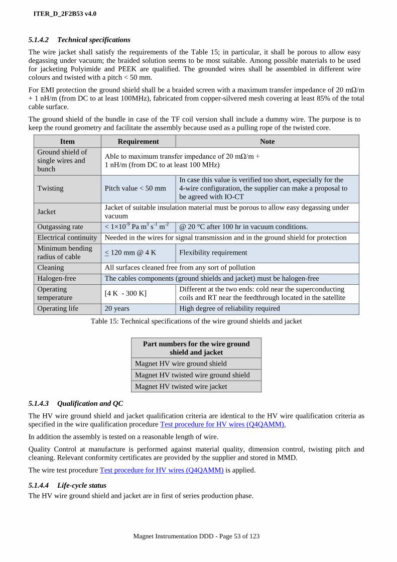
ITER_D_2F2B53 v4.0
Magnet Instrumentation DDD - Page 53 of 123
5.1.4.2 Technical specifications
The wire jacket shall satisfy the requirements of the Table 15; in particular, it shall be porous to allow easy
degassing under vacuum; the braided solution seems to be most suitable. Among possible materials to be used
for jacketing Polyimide and PEEK are qualified. The grounded wires shall be assembled in different wire
colours and twisted with a pitch < 50 mm.
For EMI protection the ground shield shall be a braided screen with a maximum transfer impedance of 20 mΩ/m
+ 1 nH/m (from DC to at least 100MHz), fabricated from copper-silvered mesh covering at least 85% of the total
cable surface.
The ground shield of the bundle in case of the TF coil version shall include a dummy wire. The purpose is to
keep the round geometry and facilitate the assembly because used as a pulling rope of the twisted core.
Table 15: Technical specifications of the wire ground shields and jacket
Part numbers for the wire ground
shield and jacket
Magnet HV wire ground shield
Magnet HV twisted wire ground shield
Magnet HV twisted wire jacket
5.1.4.3 Qualification and QC
The HV wire ground shield and jacket qualification criteria are identical to the HV wire qualification criteria as
specified in the wire qualification procedure Test procedure for HV wires (Q4QAMM).
In addition the assembly is tested on a reasonable length of wire.
Quality Control at manufacture is performed against material quality, dimension control, twisting pitch and
cleaning. Relevant conformity certificates are provided by the supplier and stored in MMD.
The wire test procedure Test procedure for HV wires (Q4QAMM) is applied.
5.1.4.4 Life-cycle status
The HV wire ground shield and jacket are in first of series production phase.
Item Requirement Note
Ground shield of
single wires and
bunch
Able to maximum transfer impedance of 20 mΩ/m +
1 nH/m (from DC to at least 100 MHz)
Twisting Pitch value < 50 mm
In case this value is verified too short, especially for the
4-wire configuration, the supplier can make a proposal to
be agreed with IO-CT
Jacket Jacket of suitable insulation material must be porous to allow easy degassing under
vacuum
Outgassing rate < 1×10⁻⁹
Pa m3 s
-1 m
-2 @ 20 °C after 100 hr in vacuum conditions.
Electrical continuity Needed in the wires for signal transmission and in the ground shield for protection
Minimum bending
radius of cable < 120 mm @ 4 K Flexibility requirement
Cleaning All surfaces cleaned free from any sort of pollution
Halogen-free The cables components (ground shields and jacket) must be halogen-free
Operating
temperature [4 K - 300 K]
Different at the two ends: cold near the superconducting
coils and RT near the feedthrough located in the satellite
Operating life 20 years High degree of reliability required

ITER_D_2F2B53 v4.0
Magnet Instrumentation DDD - Page 54 of 123
5.1.5 HV vacuum cables
5.1.5.1 Introduction
The HV vacuum cables connect the HV wires to the HV feedthroughs as shown in the Figure 4-13. The cable
connecting point on the wire side is located in the coil terminal for coils and in the ICF and CFT for feeders.
The wire-cable connecting device is called “HV Splicing device”. From that point the HV cables are routed to the
feeder instrumentation satellites where the “HV feedthroughs” are located. Most of these cables shall cross the
Vacuum Barrier (VB) to reach the HV feedthroughs; the VB crossing is performed without any cable break
thanks to the so called “HV plug”.
The HV Splicing devices, HV plugs and HV feedthrough are further specified in the sections 0, 5.1.7 and 5.1.8
respectively. The
Figure 5-16 shows an overview of the HV cable routing for the TF coils.
Figure 5-16: Overview of the HV
cable routing – TF illustration
The configuration of the HV wire - HV cable connection are governed by some rules related both to the
mitigation of the voltage perturbations induced by the variation of the magnetic field the wires are exposed and to
the schemes of the Quench Detection (QD) as specified in the section 4.5. These configurations are further
elaborated in the HV wiring loops specifications stored in the IDM folder: 11. Magnet Instrumentation Systems
and Insulating Breaks Cabling and Routing HV.
An illustration of these HV wiring loops for TF is provided in the Figure 5-17. Much more details can be found
out from the DDD11-10: Magnet Controls (JF2N9W).
Figure 5-17: Illustration of the
HV wire - HV cable connection
schemes: TF coils.
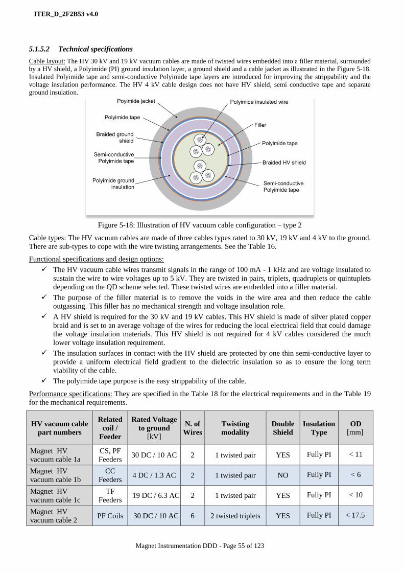
ITER_D_2F2B53 v4.0
Magnet Instrumentation DDD - Page 55 of 123
5.1.5.2 Technical specifications
Cable layout: The HV 30 kV and 19 kV vacuum cables are made of twisted wires embedded into a filler material, surrounded
by a HV shield, a Polyimide (PI) ground insulation layer, a ground shield and a cable jacket as illustrated in the Figure 5-18.
Insulated Polyimide tape and semi-conductive Polyimide tape layers are introduced for improving the strippability and the
voltage insulation performance. The HV 4 kV cable design does not have HV shield, semi conductive tape and separate
ground insulation.
Figure 5-18: Illustration of HV vacuum cable configuration – type 2
Cable types: The HV vacuum cables are made of three cables types rated to 30 kV, 19 kV and 4 kV to the ground.
There are sub-types to cope with the wire twisting arrangements. See the Table 16.
Functional specifications and design options:
The HV vacuum cable wires transmit signals in the range of 100 mA - 1 kHz and are voltage insulated to
sustain the wire to wire voltages up to 5 kV. They are twisted in pairs, triplets, quadruplets or quintuplets
depending on the QD scheme selected. These twisted wires are embedded into a filler material.
The purpose of the filler material is to remove the voids in the wire area and then reduce the cable
outgassing. This filler has no mechanical strength and voltage insulation role.
A HV shield is required for the 30 kV and 19 kV cables. This HV shield is made of silver plated copper
braid and is set to an average voltage of the wires for reducing the local electrical field that could damage
the voltage insulation materials. This HV shield is not required for 4 kV cables considered the much
lower voltage insulation requirement.
The insulation surfaces in contact with the HV shield are protected by one thin semi-conductive layer to
provide a uniform electrical field gradient to the dielectric insulation so as to ensure the long term
viability of the cable.
The polyimide tape purpose is the easy strippability of the cable.
Performance specifications: They are specified in the Table 18 for the electrical requirements and in the Table 19
for the mechanical requirements.
HV vacuum cable
part numbers
Related
coil /
Feeder
Rated Voltage
to ground [kV]
N. of
Wires
Twisting
modality
Double
Shield
Insulation
Type
OD
[mm]
Magnet HV
vacuum cable 1a
CS, PF
Feeders 30 DC / 10 AC 2 1 twisted pair YES Fully PI < 11
Magnet HV
vacuum cable 1b
CC
Feeders 4 DC / 1.3 AC 2 1 twisted pair NO Fully PI < 6
Magnet HV
vacuum cable 1c
TF
Feeders 19 DC / 6.3 AC 2 1 twisted pair YES Fully PI < 10
Magnet HV
vacuum cable 2 PF Coils 30 DC / 10 AC 6 2 twisted triplets YES Fully PI < 17.5

ITER_D_2F2B53 v4.0
Magnet Instrumentation DDD - Page 56 of 123
Table 16: HV vacuum cable types
30 kV cables
Rated voltage 30 kV DC / 10 kV AC Σ individual wires + HV
Shield Vs. ground Shield Test voltage 56 kV DC / 20 kV AC
Max. 1 min (AC), 10 min (DC).
Rated voltage 2.5 kV DC /0.9 kV AC - Between individual wires
- Σ individual wire Vs. HV
shield Test voltage
5 kV DC / 1.7 kV AC
Max. 1 min (AC), 10 min (DC).
19 kV cables
Rated voltage 19 kV DC / 6.3 kV AC Σ individual wires + HV
Shield Vs. ground Shield Test voltage 35 kV DC / 10 kV AC
Max. 1 min (AC), 10 min (DC).
Rated voltage 2.5 kV DC /0.9 kV AC - Between individual wires
- Σ individual wire Vs. HV
shield Test voltage
5 kV DC / 1.7 kV AC
Max. 1 min (AC), 10 min (DC).
4 kV cables
Rated voltage 4 kV DC / 1.3 kV AC Σ individual wires Vs. ground
Shield Test voltage 8 kV DC / 2.7 kV AC
Max. 1 min (AC), 10 min (DC)
Rated voltage 1 kV DC / 0.3 kV AC
Between individual wires Test voltage
2 kV DC / 0.7 kV AC
Max. 1 min (AC), 10 min (DC)
Table 17: Electrical performance requirements for the HV vacuum cables
Magnet HV
vacuum cable 3b CS coils 30 DC / 10 AC 8 4 twisted pairs YES Fully PI < 17
Magnet HV
vacuum cable 3b CS coils 30 DC / 10 AC 8 4 twisted pairs YES Fully PI < 17
Magnet HV
vacuum cable 4a TF Coils 19 DC / 6.3 AC 6 3 twisted pairs YES Fully PI < 15.5
Magnet HV
vacuum cable 4b TF coils 19 DC / 6.3 AC 6 2 twisted triplets YES Fully PI < 15.5
Magnet HV
vacuum cable 4c
CC
Coils 4 DC / 1.3 AC 5
1 twisted
quintuplets NO Fully PI < 11
Item Voltage requirements [kV] Galvanic separation

ITER_D_2F2B53 v4.0
Magnet Instrumentation DDD - Page 57 of 123
30 kV cables
Rated voltage 30 kV DC / 10 kV AC Σ individual wires + HV
Shield Vs. ground Shield Test voltage 56 kV DC / 20 kV AC
Max. 1 min (AC), 10 min (DC).
Rated voltage 2.5 kV DC /0.9 kV AC - Between individual wires
- Σ individual wire Vs. HV
shield Test voltage
5 kV DC / 1.7 kV AC
Max. 1 min (AC), 10 min (DC).
19 kV cables
Rated voltage 19 kV DC / 6.3 kV AC Σ individual wires + HV
Shield Vs. ground Shield Test voltage 35 kV DC / 10 kV AC
Max. 1 min (AC), 10 min (DC).
Rated voltage 2.5 kV DC /0.9 kV AC - Between individual wires
- Σ individual wire Vs. HV
shield Test voltage
5 kV DC / 1.7 kV AC
Max. 1 min (AC), 10 min (DC).
4 kV cables
Rated voltage 4 kV DC / 1.3 kV AC Σ individual wires Vs. ground
Shield Test voltage 8 kV DC / 2.7 kV AC
Max. 1 min (AC), 10 min (DC)
Rated voltage 1 kV DC / 0.3 kV AC
Between individual wires Test voltage
2 kV DC / 0.7 kV AC
Max. 1 min (AC), 10 min (DC)
Table 18: Electrical performance requirements for the HV vacuum cables
Table 19: Mechanical/Physical performance requirements for the HV vacuum cables
Item Voltage requirements [kV] Galvanic separation
Item Requirement Note
Continuous dielectric
insulation Low porosity
To ensure the galvanic separation under Paschen condition of
helium around the HV instrumentation cable.
Material Halogen free The cables must be halogen-free and that extrusion should not
carry any additives unless authorised by the IO.
Outgassing rate < 1 × 10⁻⁹
Pa m3 s
-1 m
-2
@ 20 °C after 100 hr in vacuum conditions. This excludes the
use of oils in the external layers of the cable (main insulation,
ground shield and outer jacket, though oil could be accepted in
the single wires for easing stripping – to be agreed by the IO)
Minimum bending
radius of cable < 300 mm @ RT flexibility requirement
Minimum bending
radius of wires < 30 mm @ RT flexibility requirement
Insulation stripping Stripping ability It shall be possible to strip the outer insulation jacket and the
ends of each single wire with a standard tool
Operating
temperature range [4 K - 300 K]
Different at the two ends: cold near the superconducting coils
and warm near the feedthrough located in the satellite
Operating life 20 years High degree of reliability required

ITER_D_2F2B53 v4.0
Magnet Instrumentation DDD - Page 58 of 123
Table 20: HV vacuum cables total length per cable type
5.1.5.3 Qualification and QC
The HV cable qualification scope is:
Electrical for checking the performance to DC and AC as specified in the Table 18 regarding the wire to
wire and the wire to ground insulation performance.
Mechanical for checking the cable bending, strippability and the cable pulling ability.
Cryogenic compliance regarding thermal cycles.
Vacuum compliance regarding cable outgassing.
Figure 5-19: Illustration of HV
vacuum cable spool and picture of
the stripping test
The Type Testing Plan for High-Voltage Instrumentation Cables (RGKHYT) is applied.
Quality Control at manufacture is performed against the conformity of the manufacture material certificates, the
silver plating thickness and homogeneity, the wire electrical conductivity and the strand number, the wire
assembly pitch and diameter, the cable diameter and the insulation material thickness, the dielectric voltage, the
cable concentricity, the cable weight and stripping ability. The relevant conformity certificates are provided by
the supplier and stored in MMD.
5.1.5.4 Life-cycle status
The HV vacuum cables are in first of series production phase.
The HV vacuum cable types shall be updated with the latest version of the cabling schemes
6 Still to be confirmed
7 Still to be confirmed
HV vacuum cable part numbers 6 Total length
7 (m)
Magnet HV vacuum cable 1a 2341
Magnet HV vacuum cable 1b 3058
Magnet HV vacuum cable 1c 1394
Magnet HV vacuum cable 2 1731
Magnet HV vacuum cable 3b 5340
Magnet HV vacuum cable 4a 1517
Magnet HV vacuum cable 4b 5041
Magnet HV vacuum cable 4c 3288
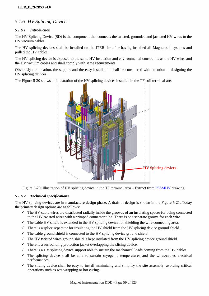
ITER_D_2F2B53 v4.0
Magnet Instrumentation DDD - Page 59 of 123
5.1.6 HV Splicing Devices
5.1.6.1 Introduction
The HV Splicing Device (SD) is the component that connects the twisted, grounded and jacketed HV wires to the
HV vacuum cables.
The HV splicing devices shall be installed on the ITER site after having installed all Magnet sub-systems and
pulled the HV cables.
The HV splicing device is exposed to the same HV insulation and environmental constraints as the HV wires and
the HV vacuum cables and shall comply with same requirements.
Obviously the location, the support and the easy installation shall be considered with attention in designing the
HV splicing devices.
The Figure 5-20 shows an illustration of the HV splicing devices installed in the TF coil terminal area.
Figure 5-20: Illustration of HV splicing device in the TF terminal area – Extract from P5SMHV drawing
5.1.6.2 Technical specifications
The HV splicing devices are in manufacture design phase. A draft of design is shown in the Figure 5-21. Today
the primary design options are as follows:
The HV cable wires are distributed radially inside the grooves of an insulating spacer for being connected
to the HV twisted wires with a crimped connector tube. There is one separate groove for each wire.
The cable HV shield is extended in the HV splicing device for shielding the wire connecting area.
There is a splice separator for insulating the HV shield from the HV splicing device ground shield.
The cable ground shield is connected to the HV splicing device ground shield.
The HV twisted wires ground shield is kept insulated from the HV splicing device ground shield.
There is a surrounding protection jacket overlapping the slicing device.
There is a HV splicing device support able to sustain the mechanical loads coming from the HV cables.
The splicing device shall be able to sustain cryogenic temperatures and the wires/cables electrical
performances.
The slicing device shall be easy to install minimizing and simplify the site assembly, avoiding critical
operations such as wet wrapping or hot curing.
HV Splicing devices

ITER_D_2F2B53 v4.0
Magnet Instrumentation DDD - Page 60 of 123
Figure 5-21: Draft design of the HV splicing device
Performance specifications
They are specified in the Table 18 for the electrical requirements (identical to the HV cables) and in the Table 21
for non-electrical requirements.
Item Requirement
Operating temperature range [4 K - 300 K]
Other Halogen free
Table 21: Non-electrical requirements for the HV plugs
Table 22: HV vacuum cables total length per cable type
5.1.6.3 Qualification and QC
The HV splicing device will be qualified against acceptance criteria similar to the HV vacuum cables save for
mechanical tests. Details and procedures are still TBD.
QC at manufacture is still TBD.
5.1.6.4 Life-cycle status
The HV Splicing Devices are in manufacture design phase.
8 Still to be confirmed
HV Splicing Device part numbers 8 Quantities
Magnet HV vacuum SD 1a 156
Magnet HV vacuum SD 1b 152
Magnet HV vacuum SD 1c 108
Magnet HV vacuum SD 2 60
Magnet HV vacuum SD 3 132
Magnet HV vacuum SD 4a 4a+4b : 234
Magnet HV vacuum SD 4b
Magnet HV vacuum SD 4c 78
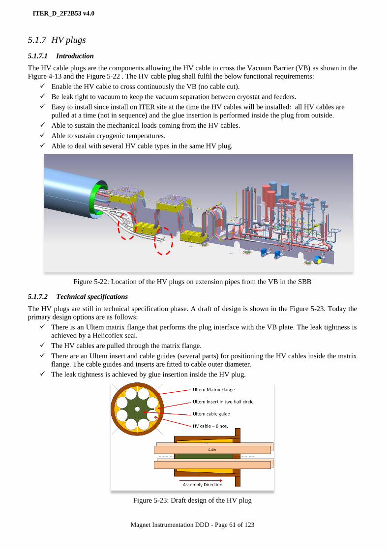
ITER_D_2F2B53 v4.0
Magnet Instrumentation DDD - Page 61 of 123
5.1.7 HV plugs
5.1.7.1 Introduction
The HV cable plugs are the components allowing the HV cable to cross the Vacuum Barrier (VB) as shown in the
Figure 4-13 and the Figure 5-22 . The HV cable plug shall fulfil the below functional requirements:
Enable the HV cable to cross continuously the VB (no cable cut).
Be leak tight to vacuum to keep the vacuum separation between cryostat and feeders.
Easy to install since install on ITER site at the time the HV cables will be installed: all HV cables are
pulled at a time (not in sequence) and the glue insertion is performed inside the plug from outside.
Able to sustain the mechanical loads coming from the HV cables.
Able to sustain cryogenic temperatures.
Able to deal with several HV cable types in the same HV plug.
Figure 5-22: Location of the HV plugs on extension pipes from the VB in the SBB
5.1.7.2 Technical specifications
The HV plugs are still in technical specification phase. A draft of design is shown in the Figure 5-23. Today the
primary design options are as follows:
There is an Ultem matrix flange that performs the plug interface with the VB plate. The leak tightness is
achieved by a Helicoflex seal.
The HV cables are pulled through the matrix flange.
There are an Ultem insert and cable guides (several parts) for positioning the HV cables inside the matrix
flange. The cable guides and inserts are fitted to cable outer diameter.
The leak tightness is achieved by glue insertion inside the HV plug.
Figure 5-23: Draft design of the HV plug

ITER_D_2F2B53 v4.0
Magnet Instrumentation DDD - Page 62 of 123
Item Requirement
Vacuum leak tightness Leak rate < 10-9
Pa m3/s
Operating temperature range [77 K - 300 K]
Other Halogen free
Table 23: Non-electrical requirements for the HV plugs
HV plugs part numbers: still TBD
5.1.7.3 Qualification and QC
The HV plugs will be qualified against vacuum leak tightness, radiation tolerance and installation feasibility. The
qualification procedure is still TBD.
QC at manufacture is still TBD.
5.1.7.4 Life-cycle status
The HV plugs are in technical specification phase.
5.1.8 HV feedthroughs
5.1.8.1 Introduction
The HV feedthroughs are the components allowing the HV signals cable to cross the feeder wall at the
instrumentation satellites, see the Figure 5-24. The HV feedthroughs shall fulfil the below functional
requirements:
Make the HV signals to cross the feeder wall.
Be air leak tight to vacuum.
Sustain the HV coming from the HV signals to the ground and pin to pin.
Make the vacuum cable disconnectable from the air cable.
Easy to install since installed on ITER site at the time the HV cables will be.
Able to sustain the mechanical loads coming from the HV cables.
Able to deal with all HV cable types.
Figure 5-24: Instrumentation satellite and feedthrough location.
5.1.8.2 Technical specifications
HV feedthrough layout: The HV feedthrough is made of two parts: one is the feedthrough part which shall fulfil
all requirements; this part is quite specific and the related requirements are not met by any market product: a
specific design is required even derived from a Commercial Off-The-Shelf (COTS) product. The second is the air
plug and can be selected from available COTS products. See the Figure 5-25.

ITER_D_2F2B53 v4.0
Magnet Instrumentation DDD - Page 63 of 123
Feedthrough types: The HV feedthroughs are
made of three types rated to 30 kV and 4 kV to
the ground. Where the wire amount is identical,
30 kV feedthroughs are used for 19 kV cables.
There are sub-types to cope with the cable wire
configuration, see the Table 16.
Figure 5-25: Picture of the HV feedthrough and
air plug
Functional specifications and design options:
The HV feedthroughs transmit signals in the range of 100 mA - 1 kHz and are voltage insulated to sustain
pin to pin voltages up to 5 kV and pin to ground up to 30 kV.
The HV feedthroughs are designed in two parts. One is fixed and is dealing with the HV vacuum cable
interface, the vacuum leak tightness and the crossing of the vacuum wall. The other is disconnectable
from the fixed part and is dealing with the HV air cable interface.
A HV shield is required for the 30 kV feedthroughs for mitigating the local electrical field gradient
around the HV pin connection and then improving the HV feedthrough HV performance regarding
electrical breakdown and Paschen discharges. This HV shield is not required for the 4 kV feedthroughs
for matching the 4 kV HV cable configuration.
The feedthrough cavity where the HV vacuum cable is connected to the feedthrough pin is resin potted
under vacuum for a better quality of the potting.
This pin connection cavity is surrounded by a HV shield which shall overlap the cable HV shield for a
good uniformity of the electrical field.
There is a Peek wire spacer for well guiding the cable wires from the cable end to the feedthrough pin
connection.
Figure 5-26: 30 kV – 6 pins HV feedthrough cross section – vacuum cable interface part.
Courtesy of CERAMTEC
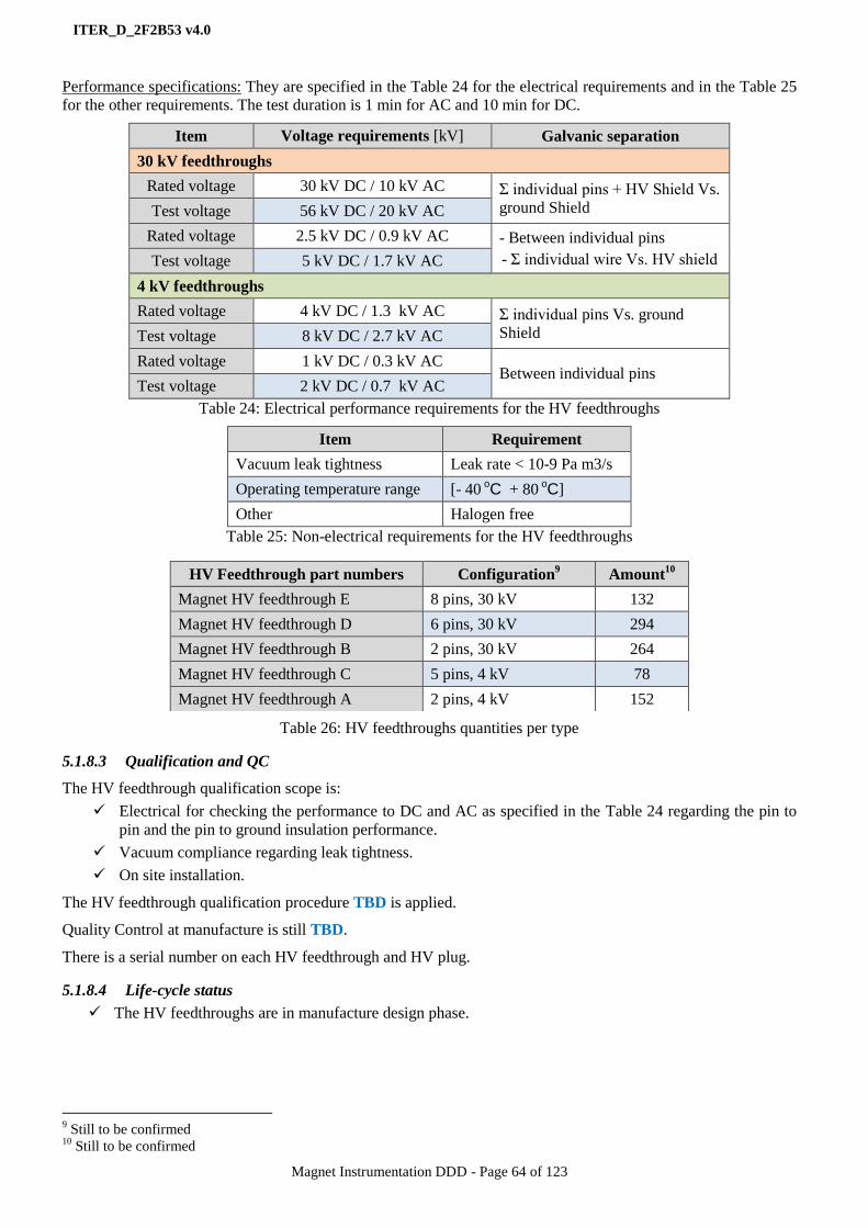
ITER_D_2F2B53 v4.0
Magnet Instrumentation DDD - Page 64 of 123
Performance specifications: They are specified in the Table 24 for the electrical requirements and in the Table 25
for the other requirements. The test duration is 1 min for AC and 10 min for DC.
Item Voltage requirements [kV] Galvanic separation
30 kV feedthroughs
Rated voltage 30 kV DC / 10 kV AC Σ individual pins + HV Shield Vs.
ground Shield Test voltage 56 kV DC / 20 kV AC
Rated voltage 2.5 kV DC / 0.9 kV AC - Between individual pins
- Σ individual wire Vs. HV shield Test voltage 5 kV DC / 1.7 kV AC
4 kV feedthroughs
Rated voltage 4 kV DC / 1.3 kV AC Σ individual pins Vs. ground
Shield Test voltage 8 kV DC / 2.7 kV AC
Rated voltage 1 kV DC / 0.3 kV AC Between individual pins
Test voltage 2 kV DC / 0.7 kV AC
Table 24: Electrical performance requirements for the HV feedthroughs
Item Requirement
Vacuum leak tightness Leak rate < 10-9 Pa m3/s
Operating temperature range [- 40 oC + 80
oC]
Other Halogen free
Table 25: Non-electrical requirements for the HV feedthroughs
Table 26: HV feedthroughs quantities per type
5.1.8.3 Qualification and QC
The HV feedthrough qualification scope is:
Electrical for checking the performance to DC and AC as specified in the Table 24 regarding the pin to
pin and the pin to ground insulation performance.
Vacuum compliance regarding leak tightness.
On site installation.
The HV feedthrough qualification procedure TBD is applied.
Quality Control at manufacture is still TBD.
There is a serial number on each HV feedthrough and HV plug.
5.1.8.4 Life-cycle status
The HV feedthroughs are in manufacture design phase.
9 Still to be confirmed
10 Still to be confirmed
HV Feedthrough part numbers Configuration9 Amount
10
Magnet HV feedthrough E 8 pins, 30 kV 132
Magnet HV feedthrough D 6 pins, 30 kV 294
Magnet HV feedthrough B 2 pins, 30 kV 264
Magnet HV feedthrough C 5 pins, 4 kV 78
Magnet HV feedthrough A 2 pins, 4 kV 152

ITER_D_2F2B53 v4.0
Magnet Instrumentation DDD - Page 65 of 123
5.1.9 HV air cable
5.1.9.1 Introduction
The HV air cables connect the HV feedthrough plugs to the HV conditioners as shown in the Figure 4-13.
The HV air cable is the extension of the HV vacuum cable behind the HV feedthrough and up to the HV
conditioner. It runs from the feeder instrumentation satellites to the HV conditioning cubicles where the HV
conditioners are.
The HV air cables are then quite similar to the HV vacuum cables regarding HV requirements and wire
configuration but the vacuum and cryogenic operating condition requirements do not apply. Also the outer
diameter requirements are relaxed since the space requirements into the air cable trays are less demanding than
those coming from the vacuum cable pipes.
In addition there is another type introduced for connecting the HV T sensor wires to the HV T sensor signal
conditioners, See the section 5.1.11.
5.1.9.2 Technical specifications
Cable layout: The HV air cables are made of twisted wires and plastic strands, surrounded by a HV shield, a
ground insulation layer, a ground shield and a cable jacket as illustrated in the Figure 5-27. Insulated material tape
and semi-conductive tape layers are introduced for improving the strippability and the voltage insulation
performance. The plastic strands are fillers to get a circular shape.
Figure 5-27: Illustration of HV air cable configuration – type 2
Cable types: The HV air cables are made of three cables types rated to 30 kV, 19 kV and 4 kV to the ground.
There are sub-types to cope with the wire twisting arrangements. See the Table 27.
Functional specifications and design options:
The HV cable wires transmit signals in the range of 100 mA - 1 kHz and are voltage insulated to sustain
the wire to wire voltages up to 5 kV. They are twisted in pairs, triplets or quadruplets depending on the
QD scheme selected. These twisted wires are embedded into a filler material.
The HV shield is required for the 30 kV and 19 kV cables. This shield is made of copper braid and is set
to an average voltage of the wires for reducing the local electrical field that could damage the voltage
insulation materials. This HV shield is not required for the 4 kV cables considered the much lower
voltage insulation requirement.
The insulation surfaces in contact with the shields are protected by one thin semi-conductive layer to
provide a uniform electrical field gradient to the dielectric insulation so as to ensure the long term
viability of the cable.
Standard requirements: Low smoke, Fire retardant, no halogen: IEC 60754
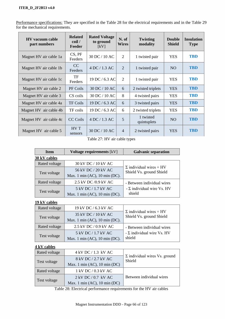
ITER_D_2F2B53 v4.0
Magnet Instrumentation DDD - Page 66 of 123
Performance specifications: They are specified in the Table 28 for the electrical requirements and in the Table 29
for the mechanical requirements.
Table 27: HV air cable types
30 kV cables
Rated voltage 30 kV DC / 10 kV AC Σ individual wires + HV
Shield Vs. ground Shield Test voltage 56 kV DC / 20 kV AC
Max. 1 min (AC), 10 min (DC).
Rated voltage 2.5 kV DC /0.9 kV AC - Between individual wires
- Σ individual wire Vs. HV
shield Test voltage
5 kV DC / 1.7 kV AC
Max. 1 min (AC), 10 min (DC).
19 kV cables
Rated voltage 19 kV DC / 6.3 kV AC Σ individual wires + HV
Shield Vs. ground Shield Test voltage 35 kV DC / 10 kV AC
Max. 1 min (AC), 10 min (DC).
Rated voltage 2.5 kV DC / 0.9 kV AC - Between individual wires
- Σ individual wire Vs. HV
shield Test voltage
5 kV DC / 1.7 kV AC
Max. 1 min (AC), 10 min (DC).
4 kV cables
Rated voltage 4 kV DC / 1.3 kV AC Σ individual wires Vs. ground
Shield Test voltage 8 kV DC / 2.7 kV AC
Max. 1 min (AC), 10 min (DC)
Rated voltage 1 kV DC / 0.3 kV AC
Between individual wires Test voltage
2 kV DC / 0.7 kV AC
Max. 1 min (AC), 10 min (DC)
Table 28: Electrical performance requirements for the HV air cables
HV vacuum cable
part numbers
Related
coil /
Feeder
Rated Voltage
to ground [kV]
N. of
Wires
Twisting
modality
Double
Shield
Insulation
Type
Magnet HV air cable 1a CS, PF
Feeders 30 DC / 10 AC 2 1 twisted pair YES TBD
Magnet HV air cable 1b CC
Feeders 4 DC / 1.3 AC 2 1 twisted pair NO TBD
Magnet HV air cable 1c TF
Feeders 19 DC / 6.3 AC 2 1 twisted pair YES TBD
Magnet HV air cable 2 PF Coils 30 DC / 10 AC 6 2 twisted triplets YES TBD
Magnet HV air cable 3 CS coils 30 DC / 10 AC 8 4 twisted pairs YES TBD
Magnet HV air cable 4a TF Coils 19 DC / 6.3 AC 6 3 twisted pairs YES TBD
Magnet HV air cable 4b TF coils 19 DC / 6.3 AC 6 2 twisted triplets YES TBD
Magnet HV air cable 4c CC Coils 4 DC / 1.3 AC 5 1 twisted
quintuplets NO TBD
Magnet HV air cable 5 HV T
sensors 30 DC / 10 AC 4 2 twisted pairs YES TBD
Item Voltage requirements [kV] Galvanic separation
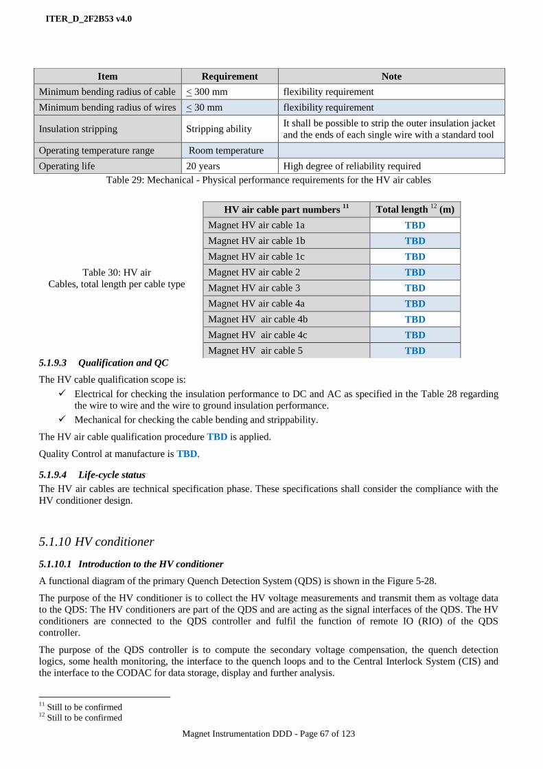
ITER_D_2F2B53 v4.0
Magnet Instrumentation DDD - Page 67 of 123
Table 29: Mechanical - Physical performance requirements for the HV air cables
Table 30: HV air
Cables, total length per cable type
5.1.9.3 Qualification and QC
The HV cable qualification scope is:
Electrical for checking the insulation performance to DC and AC as specified in the Table 28 regarding
the wire to wire and the wire to ground insulation performance.
Mechanical for checking the cable bending and strippability.
The HV air cable qualification procedure TBD is applied.
Quality Control at manufacture is TBD.
5.1.9.4 Life-cycle status
The HV air cables are technical specification phase. These specifications shall consider the compliance with the
HV conditioner design.
5.1.10 HV conditioner
5.1.10.1 Introduction to the HV conditioner
A functional diagram of the primary Quench Detection System (QDS) is shown in the Figure 5-28.
The purpose of the HV conditioner is to collect the HV voltage measurements and transmit them as voltage data
to the QDS: The HV conditioners are part of the QDS and are acting as the signal interfaces of the QDS. The HV
conditioners are connected to the QDS controller and fulfil the function of remote IO (RIO) of the QDS
controller.
The purpose of the QDS controller is to compute the secondary voltage compensation, the quench detection
logics, some health monitoring, the interface to the quench loops and to the Central Interlock System (CIS) and
the interface to the CODAC for data storage, display and further analysis.
11
Still to be confirmed 12
Still to be confirmed
Item Requirement Note
Minimum bending radius of cable < 300 mm flexibility requirement
Minimum bending radius of wires < 30 mm flexibility requirement
Insulation stripping Stripping ability It shall be possible to strip the outer insulation jacket
and the ends of each single wire with a standard tool
Operating temperature range Room temperature
Operating life 20 years High degree of reliability required
HV air cable part numbers 11
Total length 12
(m)
Magnet HV air cable 1a TBD
Magnet HV air cable 1b TBD
Magnet HV air cable 1c TBD
Magnet HV air cable 2 TBD
Magnet HV air cable 3 TBD
Magnet HV air cable 4a TBD
Magnet HV air cable 4b TBD
Magnet HV air cable 4c TBD
Magnet HV air cable 5 TBD
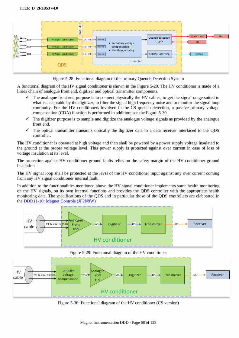
ITER_D_2F2B53 v4.0
Magnet Instrumentation DDD - Page 68 of 123
Figure 5-28: Functional diagram of the primary Quench Detection System
A functional diagram of the HV signal conditioner is shown in the Figure 5-29. The HV conditioner is made of a
linear chain of analogue front end, digitizer and optical transmitter components.
The analogue front end purpose is to connect physically the HV cables, to get the signal range suited to
what is acceptable by the digitizer, to filter the signal high frequency noise and to monitor the signal loop
continuity. For the HV conditioners involved in the CS quench detection, a passive primary voltage
compensation (CDA) function is performed in addition; see the Figure 5-30.
The digitizer purpose is to sample and digitize the analogue voltage signals as provided by the analogue
front end.
The optical transmitter transmits optically the digitizer data to a data receiver interfaced to the QDS
controller.
The HV conditioner is operated at high voltage and then shall be powered by a power supply voltage insulated to
the ground at the proper voltage level. This power supply is protected against over current in case of loss of
voltage insulation at its level.
The protection against HV conditioner ground faults relies on the safety margin of the HV conditioner ground
insulation.
The HV signal loop shall be protected at the level of the HV conditioner input against any over current coming
from any HV signal conditioner internal fault.
In addition to the functionalities mentioned above the HV signal conditioner implements some health monitoring
on the HV signals, on its own internal functions and provides the QDS controller with the appropriate health
monitoring data. The specifications of the QDS and in particular those of the QDS controllers are elaborated in
the DDD11-10: Magnet Controls (JF2N9W)
Figure 5-29: Functional diagram of the HV conditioner
Figure 5-30: Functional diagram of the HV conditioner (CS version)
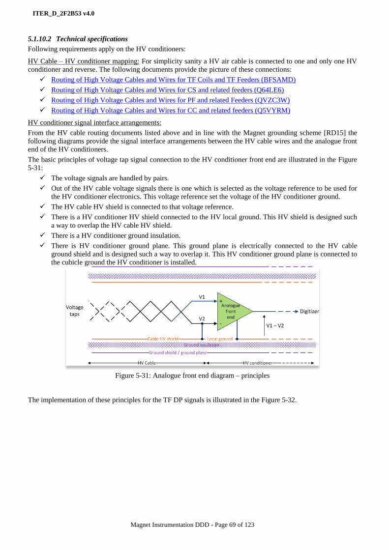
ITER_D_2F2B53 v4.0
Magnet Instrumentation DDD - Page 69 of 123
5.1.10.2 Technical specifications
Following requirements apply on the HV conditioners:
HV Cable – HV conditioner mapping: For simplicity sanity a HV air cable is connected to one and only one HV
conditioner and reverse. The following documents provide the picture of these connections:
Routing of High Voltage Cables and Wires for TF Coils and TF Feeders (BFSAMD)
Routing of High Voltage Cables and Wires for CS and related feeders (Q64LE6)
Routing of High Voltage Cables and Wires for PF and related Feeders (QVZC3W)
Routing of High Voltage Cables and Wires for CC and related feeders (Q5VYRM)
HV conditioner signal interface arrangements:
From the HV cable routing documents listed above and in line with the Magnet grounding scheme [RD15] the
following diagrams provide the signal interface arrangements between the HV cable wires and the analogue front
end of the HV conditioners.
The basic principles of voltage tap signal connection to the HV conditioner front end are illustrated in the Figure
5-31:
The voltage signals are handled by pairs.
Out of the HV cable voltage signals there is one which is selected as the voltage reference to be used for
the HV conditioner electronics. This voltage reference set the voltage of the HV conditioner ground.
The HV cable HV shield is connected to that voltage reference.
There is a HV conditioner HV shield connected to the HV local ground. This HV shield is designed such
a way to overlap the HV cable HV shield.
There is a HV conditioner ground insulation.
There is HV conditioner ground plane. This ground plane is electrically connected to the HV cable
ground shield and is designed such a way to overlap it. This HV conditioner ground plane is connected to
the cubicle ground the HV conditioner is installed.
Figure 5-31: Analogue front end diagram – principles
The implementation of these principles for the TF DP signals is illustrated in the Figure 5-32.
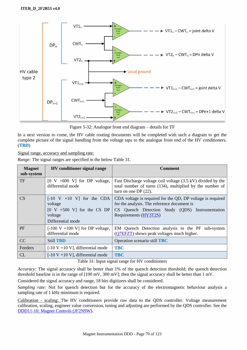
ITER_D_2F2B53 v4.0
Magnet Instrumentation DDD - Page 70 of 123
Figure 5-32: Analogue front end diagram – details for TF
In a next version to come, the HV cable routing documents will be completed with such a diagram to get the
complete picture of the signal handling from the voltage taps to the analogue front end of the HV conditioners.
(TBD)
Signal range, accuracy and sampling rate:
Range: The signal ranges are specified in the below Table 31.
Magnet
sub-system
HV conditioner signal range Comment
TF [0 V +600 V] for DP voltage,
differential mode
Fast Discharge voltage coil voltage (3.5 kV) divided by the
total number of turns (134), multiplied by the number of
turn on one DP (22).
CS [-10 V +10 V] for the CDA
voltage
[0 V +500 V] for the CS DP
voltage
Differential mode
CDA voltage is required for the QD, DP voltage is required
for the analysis. The reference document is
CS Quench Detection Study (QDS) Instrumentation
Requirements (HY3T2S)
PF [-100 V +100 V] for DP voltage,
differential mode
EM Quench Detection analysis in the PF sub-system
(Q7EFZT) shows peak voltages much higher.
CC Still TBD Operation scenario still TBC
Feeders [-10 V +10 V], differential mode TBC
CL [-10 V +10 V], differential mode TBC
Table 31: Input signal range for HV conditioners
Accuracy: The signal accuracy shall be better than 1% of the quench detection threshold; the quench detection
threshold baseline is in the range of [100 mV, 300 mV]; then the signal accuracy shall be better than 1 mV.
Considered the signal accuracy and range, 18 bits digitizers shall be considered.
Sampling rate: Not for quench detection but for the accuracy of the electromagnetic behaviour analysis a
sampling rate of 1 kHz minimum is required.
Calibration - scaling: The HV conditioners provide raw data to the QDS controller. Voltage measurement
calibration, scaling, engineer value conversion, tuning and adjusting are performed by the QDS controller. See the
DDD11-10: Magnet Controls (JF2N9W).
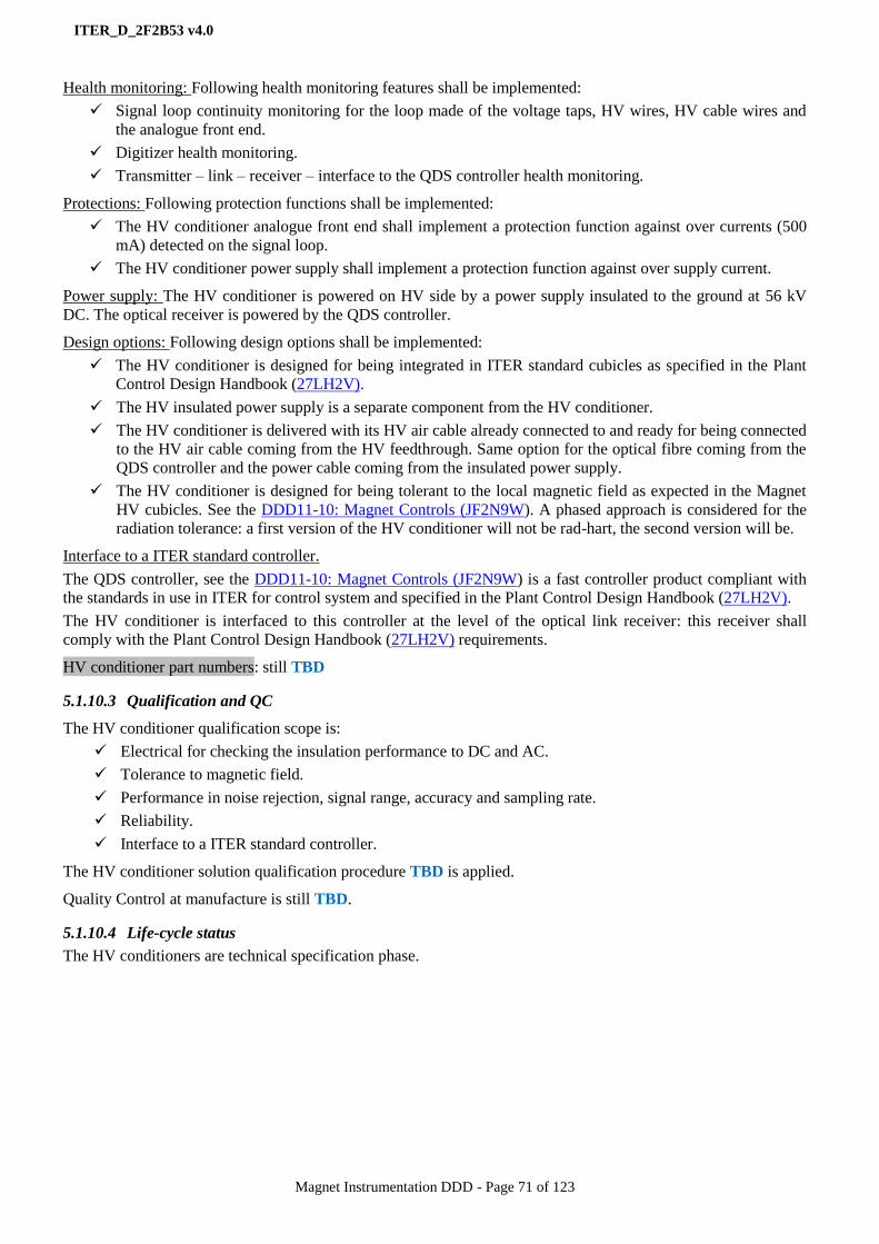
ITER_D_2F2B53 v4.0
Magnet Instrumentation DDD - Page 71 of 123
Health monitoring: Following health monitoring features shall be implemented:
Signal loop continuity monitoring for the loop made of the voltage taps, HV wires, HV cable wires and
the analogue front end.
Digitizer health monitoring.
Transmitter – link – receiver – interface to the QDS controller health monitoring.
Protections: Following protection functions shall be implemented:
The HV conditioner analogue front end shall implement a protection function against over currents (500
mA) detected on the signal loop.
The HV conditioner power supply shall implement a protection function against over supply current.
Power supply: The HV conditioner is powered on HV side by a power supply insulated to the ground at 56 kV
DC. The optical receiver is powered by the QDS controller.
Design options: Following design options shall be implemented:
The HV conditioner is designed for being integrated in ITER standard cubicles as specified in the Plant
Control Design Handbook (27LH2V).
The HV insulated power supply is a separate component from the HV conditioner.
The HV conditioner is delivered with its HV air cable already connected to and ready for being connected
to the HV air cable coming from the HV feedthrough. Same option for the optical fibre coming from the
QDS controller and the power cable coming from the insulated power supply.
The HV conditioner is designed for being tolerant to the local magnetic field as expected in the Magnet
HV cubicles. See the DDD11-10: Magnet Controls (JF2N9W). A phased approach is considered for the
radiation tolerance: a first version of the HV conditioner will not be rad-hart, the second version will be.
Interface to a ITER standard controller.
The QDS controller, see the DDD11-10: Magnet Controls (JF2N9W) is a fast controller product compliant with
the standards in use in ITER for control system and specified in the Plant Control Design Handbook (27LH2V).
The HV conditioner is interfaced to this controller at the level of the optical link receiver: this receiver shall
comply with the Plant Control Design Handbook (27LH2V) requirements.
HV conditioner part numbers: still TBD
5.1.10.3 Qualification and QC
The HV conditioner qualification scope is:
Electrical for checking the insulation performance to DC and AC.
Tolerance to magnetic field.
Performance in noise rejection, signal range, accuracy and sampling rate.
Reliability.
Interface to a ITER standard controller.
The HV conditioner solution qualification procedure TBD is applied.
Quality Control at manufacture is still TBD.
5.1.10.4 Life-cycle status
The HV conditioners are technical specification phase.
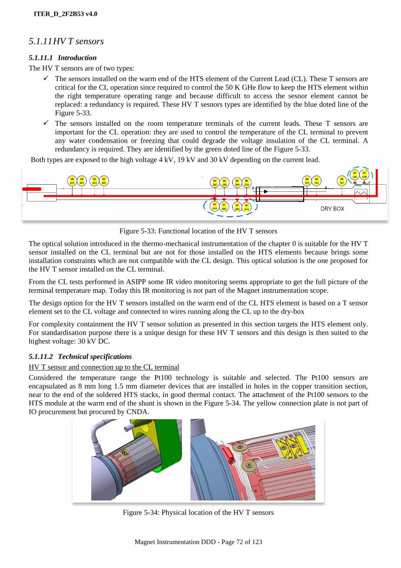
ITER_D_2F2B53 v4.0
Magnet Instrumentation DDD - Page 72 of 123
5.1.11 HV T sensors
5.1.11.1 Introduction
The HV T sensors are of two types:
The sensors installed on the warm end of the HTS element of the Current Lead (CL). These T sensors are
critical for the CL operation since required to control the 50 K GHe flow to keep the HTS element within
the right temperature operating range and because difficult to access the sesnor element cannot be
replaced: a redundancy is required. These HV T sesnors types are identified by the blue doted line of the
Figure 5-33.
The sensors installed on the room temperature terminals of the current leads. These T sensors are
important for the CL operation: they are used to control the temperature of the CL terminal to prevent
any water condensation or freezing that could degrade the voltage insulation of the CL terminal. A
redundancy is required. They are identified by the green doted line of the Figure 5-33.
Both types are exposed to the high voltage 4 kV, 19 kV and 30 kV depending on the current lead.
Figure 5-33: Functional location of the HV T sensors
The optical solution introduced in the thermo-mechanical instrumentation of the chapter 0 is suitable for the HV T
sensor installed on the CL terminal but are not for those installed on the HTS elements because brings some
installation constraints which are not compatible with the CL design. This optical solution is the one proposed for
the HV T sensor installed on the CL terminal.
From the CL tests performed in ASIPP some IR video monitoring seems appropriate to get the full picture of the
terminal temperature map. Today this IR monitoring is not part of the Magnet instrumentation scope.
The design option for the HV T sensors installed on the warm end of the CL HTS element is based on a T sensor
element set to the CL voltage and connected to wires running along the CL up to the dry-box
For complexity containment the HV T sensor solution as presented in this section targets the HTS element only.
For standardisation purpose there is a unique design for these HV T sensors and this design is then suited to the
highest voltage: 30 kV DC.
5.1.11.2 Technical specifications
HV T sensor and connection up to the CL terminal
Considered the temperature range the Pt100 technology is suitable and selected. The Pt100 sensors are
encapsulated as 8 mm long 1.5 mm diameter devices that are installed in holes in the copper transition section,
near to the end of the soldered HTS stacks, in good thermal contact. The attachment of the Pt100 sensors to the
HTS module at the warm end of the shunt is shown in the Figure 5-34. The yellow connection plate is not part of
IO procurement but procured by CNDA.
Figure 5-34: Physical location of the HV T sensors

ITER_D_2F2B53 v4.0
Magnet Instrumentation DDD - Page 73 of 123
Insulated (2 kV) copper wires type 3 are used for wiring the
temperature sensors. Within the current lead the voltages between
temperature sensor wires and the lead are low justifying the low
wire insulation requirement.
The wires shall be twisted. Shielding is ensured by routing through
the central hole in the lead out to the CL terminal feedthrough. See
the section 5.1.3 for the wire type 3 specifications and the Figure
5-39 for an illustration on mock-up.
Figure 5-35: Wiring the HV T sensors
Each lead terminal is equipped with two identical vacuum tight CL feedthroughs. The sets of voltage taps and
temperature sensors wires are connected to these CL feedthroughs and the feedthrough shell is connected
hermetically to the lead via a brazed stub tube. See the Figure 5-36 for the overview and the section 5.2.6 for the
feedthrough specifications.
Figure 5-36: Configuration of the T sensor wire extraction from the CL in the terminal area.
HV T conditioner and connection from the CL terminal:
In compliance with the HV T sensor chain model as specified in the section 4.7.3, the next step is to wire the air
side of the CL feedthrough. This will be done with HV insulated (30 kV) to ground wires. The type 2 wire as
specified in the section 5.1.3 is appropriate.
Then the HV wire type 2 is jointed to a HV air cable. This connection will be performed on ITER-site and the
details of implementation are still TBD. The proper cable to use is the Magnet HV air cable 5; see the cable
details in the section 5.1.9. The Magnet HV air cable 5 connects the HV T conditioner.
The purpose of the HV T conditioner is to collect the HV T sensor signals and transmit them as resistance data to
the Magnet control system. The conversion from resistance data to temperature data is performed by the Magnet
control system controllers. The HV T conditioner is designed to handle 2 HV T sensors out of the 4 installed in
the HTSCL CL. The remaining 2 as kept unconnected at the level of the CL feedthrough for backup purpose.
A functional diagram of the HV T conditioner is shown in the Figure 5-37. The HV T conditioner is made of a
linear chain of analogue front end, digitizer and optical transmitter components.
The analogue front end purpose is to connect physically the HV air cable 5, to power the T sensor and
get the signal range suited to what is acceptable by the digitizer, to filter the signal high frequency noise
and to monitor the signal loop continuity.
The digitizer purpose is to sample and digitize the analogue voltage signals as provided by the analogue
front end.
The optical transmitter transmits optically the digitizer data to a data receiver interfaced to the Magnet
controllers in charge of the HTSCL CL cryogenic controls.
The HV T conditioner is operated at high voltage and then shall be powered by a power supply voltage insulated
to the ground at the proper voltage level. This power supply is protected against over current in case of loss of
voltage insulation at its level.
The protection against HV conditioner ground faults relies on the safety margin of the HV T conditioner ground
insulation.

ITER_D_2F2B53 v4.0
Magnet Instrumentation DDD - Page 74 of 123
The HV T sensor signal loop shall be protected at the level of the HV conditioner input against any over current
coming from any HV signal conditioner internal fault.
In addition to the functionalities mentioned above the HV T conditioner implements some health monitoring on
the HV T sensor signals, on its own internal functions and provides the Magnet controller with the appropriate
health monitoring data. The specifications of the Magnet controller are elaborated in the DDD11-10: Magnet
Controls (JF2N9W). The other technical requirements as mentioned in the section 5.1.10 for the HV conditioners
are applicable to the HV T conditioners.
Figure 5-37: Functional diagrams of the HV T conditioner.
The top diagram is the functional one of the complete HV T conditioner. The bottom diagram is the functional
one of the analogue front end with the voltage ground references
5.1.11.3 Qualification and QC
The HV T sensor qualification scope is:
Performance for checking the HV T sensor chain accuracy.
Electrical for checking the voltage insulation to DC and AC voltages.
Tolerance to magnetic field.
Reliability.
The HV T sensor solution qualification procedure TBD is applied.
Quality Control at manufacture is still TBD.
5.1.11.4 Life-cycle status
The HV T sensors are in technical specification phase for prototyping.
13
The HV wire type 2 and 3, the HV air cable 5 and the CL feedthroughs are introduced in dedicated sections of this
document
Part numbers for the HT T sensors 13
Content Amount
Magnet HT T sensor The sensor element only 408
Magnet HV T conditioner Suited to 2 T sensors 102

ITER_D_2F2B53 v4.0
Magnet Instrumentation DDD - Page 75 of 123
5.1.12 HV CL heaters
5.1.12.1 Introduction
The Current Lead (CL) terminals are designed to be operated without any water condensation at the surface of the
terminals at the rated operation current level. Considering the various conditions of the CL cryogenic cooling and
power supplying, the temperature of the CL terminals cannot always be kept above the dew point without any
additional external heating. The envisaged heating solution is made of heating cartridges installed within the CL
terminal.
The Figure 5-38 shows a transparent view of the dry-box. The Dry-box wall is covered inside by some HV
insulation material like Epoxy or Kapton panel in order to prevent any electric breakdown between the CL
Terminals and the Dry-box chassis or earth ground.
Figure 5-38: Dry box, transparent view
For the TF coil CL at 68 kA, a heating power of 2-3 kW is estimated to be required for each warm terminal. The
warm CL terminals are designed to allow insertion of rod type heating cartridges into the terminal body. The
Figure 5-39 shows a picture of such a warm CL terminals.
Figure 5-39: View of the warm CL terminal on the 68 kA lead

ITER_D_2F2B53 v4.0
Magnet Instrumentation DDD - Page 76 of 123
5.1.12.2 Technical specifications
Several options have been assessed for the HV CL heaters. Out of them are the HV insulated cartridge and the
non-insulated cartridge solutions.
The non-insulated cartridge solution brings a smaller cartridge outer diameter and a better heat transfer but push
the HV insulation requirement to the power supply leading to export that risk out of the dry-box and to a quite
expensive solution for the power supply.
The HV insulated cartridge solution brings the opposite benefits and drawbacks. It was considered anyway the
balance is in favour of this configuration provided the proof of concept of the HV insulated cartridge is
successfully demonstrated.
Insulated cartridge:
A sketch of such an insulated cartridge is shown in the Figure 5-40. The cartridge design is based on a COTS
heating cartridge on which a voltage insulation sheath (Polyimide, Mica still TBD) is added. This design shall be
qualified regarding the heat conduction to the CL terminal and the voltage insulation performances both. Also the
ageing coming with the thermal cycles shall be checked.
These cartridges shall be easily maintainable and then replaceable. There is an attached cable for connecting the
cartridge to the dry-box terminal blocks.
Figure 5-40: sketch of the HV insulated heating cartridge
The Table 32 provides the main specifications for the heating cartridges:
Type of heating
cartridge
Heater length L
[mm]
Nominal
Power
[W]
Operating voltage
(DC)
Comments
Ø Length
Type 1 [14 - 20] 500 500 19 kV TF
Type 2 [14 - 20] 500 500 30 kV CS/PF
Type 3 [14 - 20] 250 200 5 kV CC
Table 32: Heating cartridges technical specifications
Terminal blocks:
Terminal blocks are required to connect the cartridge cables to the power unit. They are located in the dry-box.
Power units:
For being able to control individually the temperature of the CL terminals, there is one power unit allocated to
each CL terminal.
In order to supply the power to the heating cartridges DC electric power supplies shall be considered. DC supply
is required for avoiding any vibration of the electrical components of the heating cartridges from the local
magnetic fields. In order to make it simple, all power supply units have same technical specifications to satisfy
the maximum power level.
There is a control interface for implementing the control and monitoring functions. This control interface shall be
compatible with ITER standards for PLC controllers; the PCDH [AD3] applies. The operating mode of the
converter is off/on. The heating current is monitored for heating cartridge health monitoring purpose. This
measurement is pushed to the control interface.
There is an over-current protection designed to protect the power supply from heating cartridge shorts.

ITER_D_2F2B53 v4.0
Magnet Instrumentation DDD - Page 77 of 123
The Table 33 provides the main specifications for the power units:
Type of heating
cartridge
Power
(kVA)
Isolated voltage
(DC) level
Input
voltage(AC)
Output
voltage(DC)
Comments
Type 1 4 19 kV 3p 400 V 230 V TF
Type 2 4 30 kV 3p 400 V 230 V CS/PF
Type 3 1 5 kV 3p 400 V 230 V CC
Table 33: Power unit technical specifications
5.1.12.3 Qualification and QC
The HV CL heater solution qualification scope is:
Performance for heating capability.
Electrical for checking the voltage insulation to DC and AC.
Tolerance to radiation.
Ageing of the HV insulation regarding temperature cycling.
The HV CL heater qualification procedure TBD is applied.
Quality Control at manufacture is still TBD.
5.1.12.4 Life-cycle status
The HV CL heaters are in technical specification phase for prototyping.
14
The HV wire type 2 and 3, the HV air cable 5 and the CL feedthroughs are introduced in dedicated sections of this
document
Part numbers for the HV CL heaters 14
Amount
HV CL heater cartridge type 1 120
HV CL heater cartridge type 2 56
HV CL heater cartridge type 3 40
HV CL heater terminal block 216
HV CL heater power unit 102
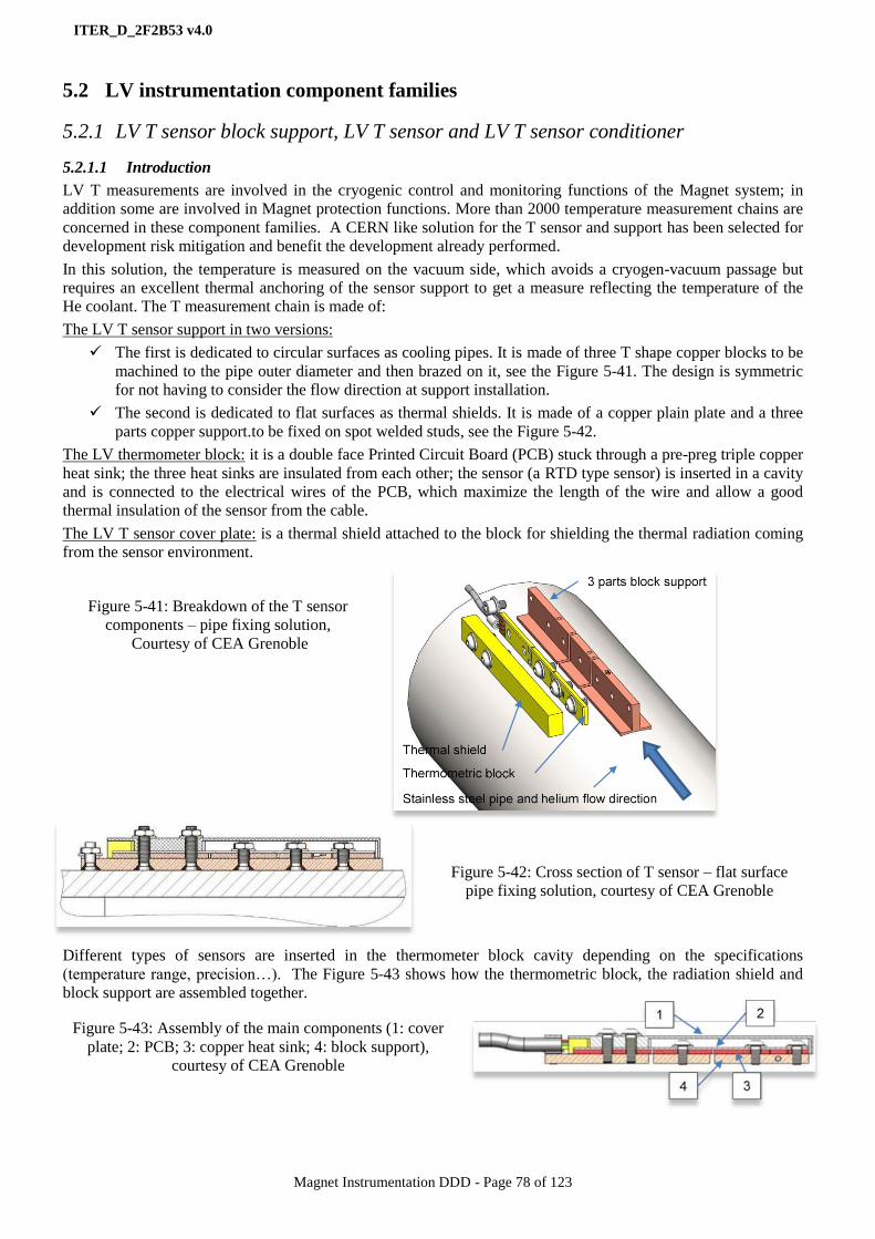
ITER_D_2F2B53 v4.0
Magnet Instrumentation DDD - Page 78 of 123
5.2 LV instrumentation component families
5.2.1 LV T sensor block support, LV T sensor and LV T sensor conditioner
5.2.1.1 Introduction
LV T measurements are involved in the cryogenic control and monitoring functions of the Magnet system; in
addition some are involved in Magnet protection functions. More than 2000 temperature measurement chains are
concerned in these component families. A CERN like solution for the T sensor and support has been selected for
development risk mitigation and benefit the development already performed.
In this solution, the temperature is measured on the vacuum side, which avoids a cryogen-vacuum passage but
requires an excellent thermal anchoring of the sensor support to get a measure reflecting the temperature of the
He coolant. The T measurement chain is made of:
The LV T sensor support in two versions:
The first is dedicated to circular surfaces as cooling pipes. It is made of three T shape copper blocks to be
machined to the pipe outer diameter and then brazed on it, see the Figure 5-41. The design is symmetric
for not having to consider the flow direction at support installation.
The second is dedicated to flat surfaces as thermal shields. It is made of a copper plain plate and a three
parts copper support.to be fixed on spot welded studs, see the Figure 5-42.
The LV thermometer block: it is a double face Printed Circuit Board (PCB) stuck through a pre-preg triple copper
heat sink; the three heat sinks are insulated from each other; the sensor (a RTD type sensor) is inserted in a cavity
and is connected to the electrical wires of the PCB, which maximize the length of the wire and allow a good
thermal insulation of the sensor from the cable.
The LV T sensor cover plate: is a thermal shield attached to the block for shielding the thermal radiation coming
from the sensor environment.
Figure 5-41: Breakdown of the T sensor
components – pipe fixing solution,
Courtesy of CEA Grenoble
Figure 5-42: Cross section of T sensor – flat surface
pipe fixing solution, courtesy of CEA Grenoble
Different types of sensors are inserted in the thermometer block cavity depending on the specifications
(temperature range, precision…). The Figure 5-43 shows how the thermometric block, the radiation shield and
block support are assembled together.
Figure 5-43: Assembly of the main components (1: cover
plate; 2: PCB; 3: copper heat sink; 4: block support),
courtesy of CEA Grenoble
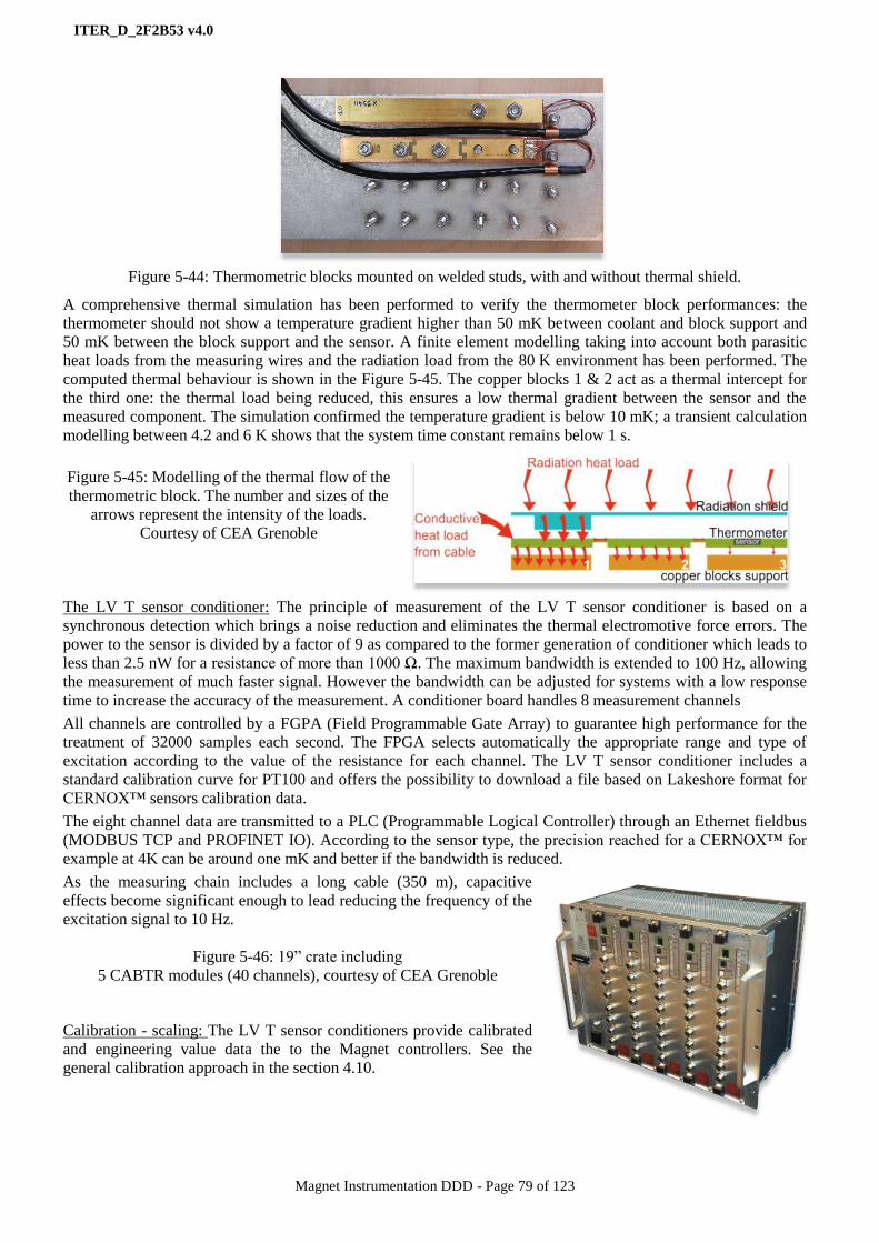
ITER_D_2F2B53 v4.0
Magnet Instrumentation DDD - Page 79 of 123
Figure 5-44: Thermometric blocks mounted on welded studs, with and without thermal shield.
A comprehensive thermal simulation has been performed to verify the thermometer block performances: the
thermometer should not show a temperature gradient higher than 50 mK between coolant and block support and
50 mK between the block support and the sensor. A finite element modelling taking into account both parasitic
heat loads from the measuring wires and the radiation load from the 80 K environment has been performed. The
computed thermal behaviour is shown in the Figure 5-45. The copper blocks 1 & 2 act as a thermal intercept for
the third one: the thermal load being reduced, this ensures a low thermal gradient between the sensor and the
measured component. The simulation confirmed the temperature gradient is below 10 mK; a transient calculation
modelling between 4.2 and 6 K shows that the system time constant remains below 1 s.
Figure 5-45: Modelling of the thermal flow of the
thermometric block. The number and sizes of the
arrows represent the intensity of the loads.
Courtesy of CEA Grenoble
The LV T sensor conditioner: The principle of measurement of the LV T sensor conditioner is based on a
synchronous detection which brings a noise reduction and eliminates the thermal electromotive force errors. The
power to the sensor is divided by a factor of 9 as compared to the former generation of conditioner which leads to
less than 2.5 nW for a resistance of more than 1000 Ω. The maximum bandwidth is extended to 100 Hz, allowing
the measurement of much faster signal. However the bandwidth can be adjusted for systems with a low response
time to increase the accuracy of the measurement. A conditioner board handles 8 measurement channels
All channels are controlled by a FGPA (Field Programmable Gate Array) to guarantee high performance for the
treatment of 32000 samples each second. The FPGA selects automatically the appropriate range and type of
excitation according to the value of the resistance for each channel. The LV T sensor conditioner includes a
standard calibration curve for PT100 and offers the possibility to download a file based on Lakeshore format for
CERNOX™ sensors calibration data.
The eight channel data are transmitted to a PLC (Programmable Logical Controller) through an Ethernet fieldbus
(MODBUS TCP and PROFINET IO). According to the sensor type, the precision reached for a CERNOX™ for
example at 4K can be around one mK and better if the bandwidth is reduced.
As the measuring chain includes a long cable (350 m), capacitive
effects become significant enough to lead reducing the frequency of the
excitation signal to 10 Hz.
Figure 5-46: 19” crate including
5 CABTR modules (40 channels), courtesy of CEA Grenoble
Calibration - scaling: The LV T sensor conditioners provide calibrated
and engineering value data the to the Magnet controllers. See the
general calibration approach in the section 4.10.

ITER_D_2F2B53 v4.0
Magnet Instrumentation DDD - Page 80 of 123
5.2.1.2 Technical specifications
LV T measurement chain specifications:
4K – 300 K range:
Standard precision:
- Resolution: 0.1 K
- ± 0.2 K below 10 K
- ± 1 K between 10 K and 80 K
- ± 10 K above 80 K
- Three points calibration: 4 K, 77 K and 300 K. Then a best fit with similar T sensor calibration
data is performed from CERN data.
High precision:
- Resolution: 50 mK below 100 K, 0.1 K above
- ± 0.1 K from 4.2 K to 10 K
- ± 0.3 K between 10 K and 80 K
- ± 0.5 K above 80 K
- Full calibration over the temperature range.
50 K – 300 K range:
Class A or better from 173 K to 300K and class B from 77K to 173 K as specified in the IEC 751-95 in
two versions: uncalibrated and calibrated.
LV T sensor:
4K – 300 K range: RTD CERNOX™ technology in two versions: Fully calibrated over the range span
and standard calibration on three points (295 K, 77 K, 4.2 K). For fully calibrated CERNOX™ the
accuracy is better than 7 mK and the long-term stability better than 5 mK.
50K – 300K range: RTD Platinum technology in two versions: Fully calibrated over the range span and
not calibrated but compliant with the class A and class B requirements as specified in the IEC 751-95.
LV T sensor cable:
2 twisted pairs of AWG28 silver plated wire, single shielded for the sensor cable. The cable length is
suited to what is required for connecting the local LV patch panel.
Compliant with the vacuum handbook [AD4].
Figure 5-47: Cable layout, 1 = twisted wire, 2 = braided ground shield, 3&4 Insulation layers
LV T sensor RT feedthrough:
Still TBD
LV T sensor conditioner specifications:
Dissipated power < 25 nW for R=1000 Ω
Synchronous detection.
Bandwidth 100 Hz.
1 kHz acquisition rate for each channel.
Communication PROFINET IO & Modbus TCP.
EMC: 61000-4-4, criterion A.
350 m sensor cables.
40 channels per crate.

ITER_D_2F2B53 v4.0
Magnet Instrumentation DDD - Page 81 of 123
Quantities:
840 chains for the high precision [4 K 300 K] range, 320 chains for the standard precision [4 K 300 K] range and
450 chains for the [50 K 300 K] range uncalibrated sensors and the same amount for the calibrated sensors will be
manufactured.
Allocation:
The high precision [4 K 300 K] range sensors are allocated to coil, busbar inlets and outlets.
The standard precision [4 K 300 K] range sensors to the cryogenic controls into the feeders.
The [50 K 300 K] range sensors are allocated to the 50 K (calibrated version) and 80 K circuits
(uncalibrated version)
5.2.1.3 Qualification and QC
The qualification has been performed regarding the measurement performance, radiation tolerance, magnetic field
tolerance and the LV T sensor installation.
Measurement performance qualification: In order to validate the whole measurement chain, a test cryostat
has been designed and manufactured for reproducing the most salient features of the LV T sensor chain.
In addition this cryostat is used for the acceptance tests of the chain components.
The results of measurements @ 4 K and 80 K have been checked against a reference calibrated temperature
sensor using the complete T measurement chain solution. The results fully satisfy the technical specifications, see
the Figure 5-49. The LV T measurement chain qualification procedure TBD is applied.
Part numbers for the LV T measurement Content
Magnet T sensor block support The LV T sensor support to be grazed on pipes
Magnet T sensor flat support The LV T sensor support for flat surfaces
Magnet T sensor Pt 100 kit The set of LV thermometer block equipped with a
platinum sensor plus the sensor cable, the LV T
sensor cover plate and the fixing set to the support.
Magnet T sensor calibrated Pt100 kit Same as Pt 100 kit but equipped with a platinum
sensor calibrated at 77 K and 300 K.
Magnet T sensor calibrated Cernox kit Same as Pt 100 kit but equipped with a high precision
CERNOX™ sensor calibrated on the full range span
Magnet T sensor un-calibrated Cernox kit Same as Pt 100 kit but equipped with a standard
precision CERNOX™ sensor calibrated on three
points.
Magnet T sensor conditioner The LV T sensor conditioner
Figure 5-48: The experimental test
cryostat: design and components,
courtesy of CEA Grenoble
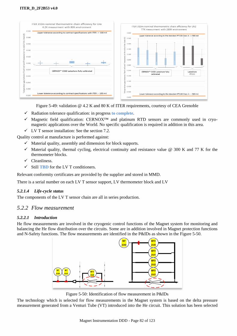
ITER_D_2F2B53 v4.0
Magnet Instrumentation DDD - Page 82 of 123
Figure 5-49: validation @ 4.2 K and 80 K of ITER requirements, courtesy of CEA Grenoble
Radiation tolerance qualification: in progress to complete.
Magnetic field qualification: CERNOX™ and platinum RTD sensors are commonly used in cryo-
magnetic applications over the World. No specific qualification is required in addition in this area.
LV T sensor installation: See the section 7.2.
Quality control at manufacture is performed against:
Material quality, assembly and dimension for block supports.
Material quality, thermal cycling, electrical continuity and resistance value @ 300 K and 77 K for the
thermometer blocks.
Cleanliness.
Still TBD for the LV T conditioners.
Relevant conformity certificates are provided by the supplier and stored in MMD.
There is a serial number on each LV T sensor support, LV thermometer block and LV
5.2.1.4 Life-cycle status
The components of the LV T sensor chain are all in series production.
5.2.2 Flow measurement
5.2.2.1 Introduction
He flow measurements are involved in the cryogenic control functions of the Magnet system for monitoring and
balancing the He flow distribution over the circuits. Some are in addition involved in Magnet protection functions
and N-Safety functions. The flow measurements are identified in the P&IDs as shown in the Figure 5-50.
Figure 5-50: Identification of flow measurement in P&IDs
The technology which is selected for flow measurements in the Magnet system is based on the delta pressure
measurement generated from a Venturi Tube (VT) introduced into the He circuit. This solution has been selected

ITER_D_2F2B53 v4.0
Magnet Instrumentation DDD - Page 83 of 123
for its reliability and its compliance with to the harsh environmental conditions of ITER, in particular regarding
magnetic field and radiation.
But this technology provides a volumetric flow while in many cases a mass flow is required. For this reason He
temperature and absolute pressure measurements are always associated to the VTs as it is shown in the Figure
5-50. The temperature measurements are installed upstream to the VT.
The flow measurement solution includes the VT, the capillary tubes for connecting the VT pressure taps to the
pressure transducers, the capillary tube feedthrough and the differential pressure transducers and associated signal
conditioners.
For contract optimisation the differential pressure transducers and the signal conditioners have been pushed to the
pressure transducer procurement scope (absolute and differential all included). The capillary tube feedthrough is
made of a simple vacuum flange fitted to connect the vacuum capillary tubes to the air capillary tubes, see the
Figure 4-17 of the section 4.7.5.
Most of the VTs are operated at cryogenic temperature but some are installed into the dry-box for the control and
monitoring of the Current Lead cooling are operated at RT.
For cost saving and considered the amount of VT to manufacture, the approach is to perform a design which
offers high repeatability in manufacture, reduces the geometrical uncertainties and improves the final helium
flowrate measurement accuracy.
The VT design follows the standard NF EN ISO 5167-4; a picture of the VT is shown in the Figure 5-51.
Figure 5-51: Illustration of a Venturi tube for TF, courtesy of CEA Grenoble
Venturis tubes for Magnet N-Safety functions: they are those involved in the TF magnets Fast Discharge safety
I&C function (6QCZT5). These TF VTs are SIC components used for detecting the reverse He flow generated by
the massive heat load deposition in the SHe TF coolant coming from the TF coil quench event.
The Figure 5-52 shows the delta pressure from the inlet pressure tap along the VT axis and along the time from
the quench initiation: whatever the flow direction the delta pressure keeps positive even if its value is significantly
increased a few seconds behind the quench event.
The delta pressure detection device will be SIC as this TF VT is; for being reliable such SIC components are
using simplistic technologies which are not able to detect reliably such pressure profile. To solve this issue a third
pressure tap has been added at the TF VT outlet for generating a reverse delta pressure for a reverse flow, this
third tap is located in the middle of the VT divergent.

ITER_D_2F2B53 v4.0
Magnet Instrumentation DDD - Page 84 of 123
Figure 5-52: Differential pressure versus pressure tap position along the VT at different steps of time after a TF
quench event, courtesy of CEA Grenoble
5.2.2.2 Technical specifications
The VT flow range and quantities requirements are specified in the Table 34:
VT size Pipe size Mass flowrate Operating
temperature
Operating
Pressure
DN8 DN 8 0.1 to 1 g/s Near 300 K 3 to 4 bars
DN10 DN 10 1 to 7 g/s Near 300 K 3 to 4 bars
DN15.20 DN 15 2 to 20 g/s 4.2 to 6 K 4 to 6 bars
DN15.30 DN 15 3 to 30 g/s 4.2 to 6 K 4 to 6 bars
DN20 DN 20 13 to 130 g/s 4.2 to 6 K 4 to 6 bars
DN25 DN 25 40 to 400 g/s 4.2 to 6 K 4 to 6 bars
DN25 3 taps DN 25 40 to 400 g/s 4.2 to 6 K 4 to 6 bars
Table 34: VT nominal flowrate specifications at nominal operation
Other requirements:
Pressure drop: from 50 mbar to 100 mbar depending on the Venturi tube type.
Material: seamless austenitic stainless steel, grade AISI 316L.
Mechanical requirements: Due to the difficulty of installing the VT flowmeters in a completely stress-free
environment, the minimum wall thickness of the VT body must be equal or greater than the wall
thickness of the connecting pipework.
Pressure: design 30 bars, test 43 bars.
Leak tightness: < 1x 10⁻⁹
Pa m3/s at 43 bars.
Accuracy: the required absolute accuracy of the measured mass flow rate is set to +/- 5% of the full scale
at nominal operation. The accuracy of the thermometry is around +/- 2.5 % of the measured value @ 4 K
(0.1 K); the accuracy of the absolute pressure transducer must be equal or better than 0.2 % of the full
scale, whilst that of the differential pressure transducers must be equal or better than 0.25 % of the full
scale. The Figure 5-53 shows the variation of this accuracy versus the mass flow rate; the dramatic

ITER_D_2F2B53 v4.0
Magnet Instrumentation DDD - Page 85 of 123
degradation of the flow accuracy at low flow is the result of the very low delta pressure, the volumetric
flow differential pressure square root dependency and the accuracy of the differential pressure transducer.
Figure 5-53: Predicted flow measurement accuracy versus flow rate for the DN25 400 g/s VTs
Installation requirements:
- Space reservations: maximum length from 800 mm to 250 mm depending on the VT type.
- Pressure tap capillary tubes: OD 6 mm, thickness 1 mm.
- In order to get a stable flow at the upstream or restriction pressure taps, as well as flows as
axisymmetric for a correct flow measurement, it is mandatory to install a sufficient length of
straight piping before the upstream pressure tap. These lengths indicated as a number of inner
tube diameters are given in the Table 35.
VT Size Total allowed length
(mm)
Required number of
upstream inner diameter
DN 8 250 8
DN 10 250 10
DN 15-20 300 8
DN 15-30 300 8
DN 20 500 8
DN 25 800 10
DN 25 3 taps 800 10
Table 35: Minimum length of straight pipe upstream to the VT
Part numbers for Venturi tubes Amount
Magnet warm DN 8 Venturi tubes 18
Magnet warm DN 10 Venturi tubes 42
Magnet cold DN15.20 Venturi tubes 89
Magnet cold DN15.30 Venturi tubes 28
Magnet cold DN20 Venturi tubes 40
Magnet cold DN25 Venturi tubes 42
Magnet cold DN25 TF Venturi tubes 18

ITER_D_2F2B53 v4.0
Magnet Instrumentation DDD - Page 86 of 123
5.2.2.3 Qualification and QC
Cryogenic VTs (DN 15, 20 and 25) will be used in the
cryogenic conditions as specified in the Table 34.
For qualification purpose the CEA HELIOS test
facility is used. The VT will be flow tested and the
measured flowrate compared to the measured
flowrate from Coriolis flowmeters. The benefit of the
Coriolis flowmeter is that it does not require any
determination of the helium density to get the mass
flowrate.
The warm flowmeters will be flow calibrated on a
warm bench.
Figure 5-54: VT leak test facility, courtesy of CEA
Grenoble
Figure 5-55: HELIOS cold test facility, courtesy of CEA
Grenoble
Figure 5-56: Configuration of VT testing in the HELIOS
test facility: 3 parallel branches equipped with 3 VTs and
a Coriolis flowmeter downstream.
The VT qualification procedure TBD is applied.
For the whole production the Quality Control at
manufacture is performed against:
Material quality.
Welding inspection.
Assembly and dimension.
Pressure tests.
Thermal cycling.
He leak tightness.
Cleanness.
The flow measurement performance is controlled for a
part of the production only.
5.2.2.4 Life-cycle status
The Venturi tubes are in series production to get the prototype samples that will be submitted to the qualification.
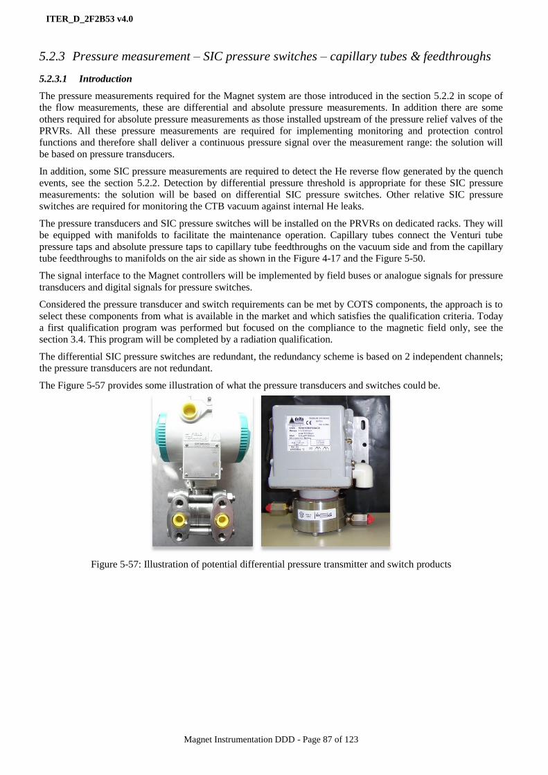
ITER_D_2F2B53 v4.0
Magnet Instrumentation DDD - Page 87 of 123
5.2.3 Pressure measurement – SIC pressure switches – capillary tubes & feedthroughs
5.2.3.1 Introduction
The pressure measurements required for the Magnet system are those introduced in the section 5.2.2 in scope of
the flow measurements, these are differential and absolute pressure measurements. In addition there are some
others required for absolute pressure measurements as those installed upstream of the pressure relief valves of the
PRVRs. All these pressure measurements are required for implementing monitoring and protection control
functions and therefore shall deliver a continuous pressure signal over the measurement range: the solution will
be based on pressure transducers.
In addition, some SIC pressure measurements are required to detect the He reverse flow generated by the quench
events, see the section 5.2.2. Detection by differential pressure threshold is appropriate for these SIC pressure
measurements: the solution will be based on differential SIC pressure switches. Other relative SIC pressure
switches are required for monitoring the CTB vacuum against internal He leaks.
The pressure transducers and SIC pressure switches will be installed on the PRVRs on dedicated racks. They will
be equipped with manifolds to facilitate the maintenance operation. Capillary tubes connect the Venturi tube
pressure taps and absolute pressure taps to capillary tube feedthroughs on the vacuum side and from the capillary
tube feedthroughs to manifolds on the air side as shown in the Figure 4-17 and the Figure 5-50.
The signal interface to the Magnet controllers will be implemented by field buses or analogue signals for pressure
transducers and digital signals for pressure switches.
Considered the pressure transducer and switch requirements can be met by COTS components, the approach is to
select these components from what is available in the market and which satisfies the qualification criteria. Today
a first qualification program was performed but focused on the compliance to the magnetic field only, see the
section 3.4. This program will be completed by a radiation qualification.
The differential SIC pressure switches are redundant, the redundancy scheme is based on 2 independent channels;
the pressure transducers are not redundant.
The Figure 5-57 provides some illustration of what the pressure transducers and switches could be.
Figure 5-57: Illustration of potential differential pressure transmitter and switch products

ITER_D_2F2B53 v4.0
Magnet Instrumentation DDD - Page 88 of 123
5.2.3.2 Technical specifications
The specifications for absolute transducers, differential transducers, differential switches and relative pressure
switches are specified in the Table 36, Table 37, Table 38 and Table 39 respectively.
Absolute pressure transducers
Item Requirement Note
Measuring range 0 – 30 bars Absolute pressure
Accuracy < +/- 0.1 % Of the full scale (FS)
Stability < +/- 0.1 % Of the full scale
Signal interface Analogue 4-20 mA or
PROFIBUS/PROFINET/HART
Optional: In such a case the transducer is
also performing the signal conditioning.
This option will be considered for a first
version not rad-hard of the transducer
waiting for the final rad-hard version.
Power supply 24 V DC -
Over range protection > 2 x FS (60 bars) -
Burst pressure > 3 x FS (90 bars) -
Operational lifetime 20 years -
Pressure cycles > 100 millions -
Leak tightness < 1x 10⁻⁹
Pa m3/s @ 43 bars. Including manifolds and connections to
the capillary tubes
Table 36: Specifications for the absolute pressure transducers
Differential pressure transducers
Item Requirement Note
Measuring range 0 - 200 mbar Differential pressure. All the All the
Venturi tubes are designed for maximum
200 mbar differential pressure at max
flowrate conditions.
Accuracy < +/- 0.1 % Of the full scale
Stability < +/- 0.1 % Of the full scale
Signal interface Analogue 4-20 mA or
PROFIBUS/PROFINET/HART
-
Power supply 24 V DC -
Over range protection > 160 bars -
Burst pressure > 90 bars -
Operational lifetime 20 years -
Pressure cycles > 100 millions -
Leak tightness < 1x 10⁻⁹
Pa m3/s @ 43 bars. Including manifolds and connections to
the capillary tubes
Table 37: Specifications for the differential pressure transducers

ITER_D_2F2B53 v4.0
Magnet Instrumentation DDD - Page 89 of 123
Differential SIC pressure switches
Item Requirement Note
Measuring range TBD Differential pressure
Accuracy < +/- 1 % Of the full scale
Stability < +/- 1 % Of the full scale
Signal interface Dry contact – 1 A – 24 V DC -
Over range protection > 30 bars -
Burst pressure > 60 bars -
Operational lifetime 20 years -
Pressure cycles > 100 millions -
Leak tightness < 1x 10⁻⁹
Pa m3/s @ 43 bars. Including manifolds and connections
to the capillary tubes
SIC class SIC 2B
Table 38: Specifications for the differential pressure transducers
Relative SIC pressure switches
Item Requirement Note
Measuring range -1 bar to + 200 mbar Relative pressure to the atmosphere
Other items As for the differential SIC pressure switches
Table 39: Specifications for the differential pressure transducers
Capillary tubes for pressure taps
There are vacuum capillary tubes and air capillary tubes; both are sharing the specifications of the Table 40.
Item Requirement
Material AISI 316 L
ID 4 mm
OD 6 ± 0.1 mm
Wall 1 mm
Test pressure 43 bar
Leak tightness 1x 10⁻⁹
Pa m3/s @ 43 bars.
Surface average roughness < 3.2
Seamless and annealed tube Yes
Cleaned surface Yes
Table 40: vacuum and air capillary tube specifications
Capillary tube feedthroughs
Details are still TBD. The basic idea is to start from a standard SS vacuum flange equipped with SS pipes at the
OD of the pressure tap capillary tubes. The flange pipes are connected/welded to the capillary tubes on vacuum
side. Then the flange is installed on the CTB, the air capillary tubes are connected/welded on the flange side and
the pressure transducer manifold at the other end. A leak test is performed by He capillary tube pressurization.
Part numbers for the pressure measurement
components
Amounts
Magnet absolute pressure transducer TBD
Magnet differential pressure transducer TBD
Magnet SIC differential pressure switch 36
Magnet SIC relative pressure switch 58

ITER_D_2F2B53 v4.0
Magnet Instrumentation DDD - Page 90 of 123
5.2.3.3 Qualification and QC
To complete with the CEA qualification outcomes when available
Figure 5-58: Picture of the magnetic field test facility,
courtesy of CEA Grenoble
5.2.3.1 Life-cycle status
The absolute pressure transmitters, differential pressure
transmitters, SIC differential pressure switches and manifolds
are in technical specification phase.
5.2.4 Patch panels – LV patch-panels and optical patch panels
The general scheme for LV cabling arrangements (vacuum and air) is defined in the LV instrumentation signals
distribution for TF feeder (QVHFVC). This document is focused on the TF magnet but the exposed principles are
applicable to any other Magnet sub-system.
5.2.4.1 Introduction to the LV patch panels
The LV Patch-Panels (PP) are parts of the LV measurement chains as introduced in the section 4.7.4. The purpose
of the LV PPs is to collect the LV signals of instrumentation components installed into the cryostat and feeders in
order to create batches of LV signals transmitted by LV trunk cables for cabling optimisation. See the cabling
scheme of the Figure 5-59.
The LV PPs shall be designed to sustain the cryogenic, vacuum, magnetic field and radiation conditions detailed
in the chapter 3.4 and shall comply with the LV grounding scheme specified in the chapter 4.9.2.
Because some of the LV PPs will be located in difficult to access area, the installation easiness is an important
design criterion. For the same reason, some of the LV patch-panels shall be installed at magnet component
manufacture as for the feeders. In such a case the LV sensors (typically the LV T sensors) are installed and
connected to the LV patch-panels for preparing the further connection of the LV trunk cable.
The LV PPs shall comply with the grounding scheme selected for the Magnet system; see the section 4.9.2 for the
LV signals inside the cryostat. The LV patch panel is acting as a junction box extending the LV trunk cables. It is
made of a metallic enclosure with limited paths for electromagnetic interferences shielding and voltage insulated
from the surface it is installed to be protected from eddy currents running into the structures. See the Figure 5-60.
Figure 5-59: LV cabling scheme in vacuum area
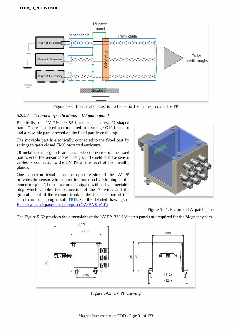
ITER_D_2F2B53 v4.0
Magnet Instrumentation DDD - Page 91 of 123
Figure 5-60: Electrical connection scheme for LV cables into the LV PP
5.2.4.2 Technical specifications – LV patch panel
Practically, the LV PPs are SS boxes made of two U shaped
parts. There is a fixed part mounted to a voltage G10 insulator
and a movable part screwed on the fixed part from the top.
The movable part is electrically connected to the fixed part by
springs to get a closed EMC protected enclosure.
10 metallic cable glands are installed on one side of the fixed
part to enter the sensor cables. The ground shield of these sensor
cables is connected to the LV PP at the level of the metallic
glands.
One connector installed at the opposite side of the LV PP
provides the sensor wire connection function by crimping on the
connector pins. The connector is equipped with a disconnectable
plug which enables the connection of the 40 wires and the
ground shield of the vacuum trunk cable. The selection of this
set of connector-plug is still TBD. See the detailed drawings in
Electrical patch panel design report (QZ8BNK v1.0)
Figure 5-61: Picture of LV patch panel
The Figure 5-62 provides the dimensions of the LV PP. 330 LV patch panels are required for the Magnet system.
Figure 5-62: LV PP drawing

ITER_D_2F2B53 v4.0
Magnet Instrumentation DDD - Page 92 of 123
5.2.4.3 Introduction to the optical patch panels
The purpose of the optical patch panel is identical to the electrical patch panels: collect the signals coming from
the optical measurement loops to get them out of the instrumentation feeders through optical trunk cables and
optical feedthroughs.
The design requirements for the environmental constraints and access are identical. The grounding requirements
are not relevant.
The optical patch panels are all installed on ITER site at the time the optical measurements are.
5.2.4.4 Technical specifications – Optical patch panel
The optical patch panels are designed a modular way for housing splice trays. The optical fiber cables enter the
optical patch panels through cable glands, then they are fanned out over these splice trays. The primary purpose
of the splice trays is to protect the spliced area and fix in loops the free length of the optical fiber cables. A splice
trays is designed for 6 splices, a total of 180 splice trays are distributed over 40 optical patch panels for all
Magnet sub-systems optical measurements
These optical patch panels are each one fitted to the local need using the modular design for dealing with splicing
of 6 and 42 optical fiber cables.
The fiber splicing is performed on-site using a separate splicing device.
Figure 5-63: Optical patch-panel and splice tray layouts.
Figure 5-64: Splice tray arrangement.
5.2.4.5 Qualification and QC
The LV patch-panel qualification is performed regarding installation feasibility for checking the sensor cable
connection to the LV PP connector, radiation tolerance of the connector and plug and thermal cycling tolerance.
The Quality Control at manufacture is performed against:
Material quality.
Assembly and dimension.
Cleanness.
5.2.4.6 Life-cycle status
The LV and optical patch panels are in series production.
Part numbers for patch panels Amount
Magnet LV patch panel
Magnet OPT patch panel
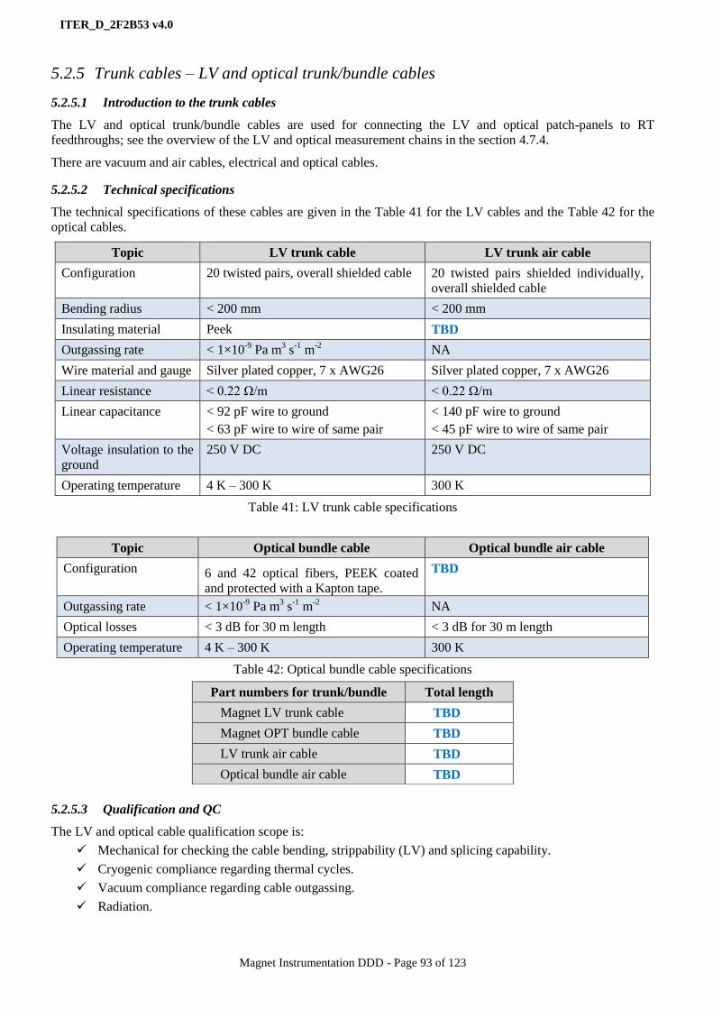
ITER_D_2F2B53 v4.0
Magnet Instrumentation DDD - Page 93 of 123
5.2.5 Trunk cables – LV and optical trunk/bundle cables
5.2.5.1 Introduction to the trunk cables
The LV and optical trunk/bundle cables are used for connecting the LV and optical patch-panels to RT
feedthroughs; see the overview of the LV and optical measurement chains in the section 4.7.4.
There are vacuum and air cables, electrical and optical cables.
5.2.5.2 Technical specifications
The technical specifications of these cables are given in the Table 41 for the LV cables and the Table 42 for the
optical cables.
Topic LV trunk cable LV trunk air cable
Configuration 20 twisted pairs, overall shielded cable 20 twisted pairs shielded individually,
overall shielded cable
Bending radius < 200 mm < 200 mm
Insulating material Peek TBD
Outgassing rate < 1×10⁻⁹
Pa m3 s
-1 m
-2 NA
Wire material and gauge Silver plated copper, 7 x AWG26 Silver plated copper, 7 x AWG26
Linear resistance < 0.22 Ω/m < 0.22 Ω/m
Linear capacitance < 92 pF wire to ground
< 63 pF wire to wire of same pair
< 140 pF wire to ground
< 45 pF wire to wire of same pair
Voltage insulation to the
ground
250 V DC 250 V DC
Operating temperature 4 K – 300 K 300 K
Table 41: LV trunk cable specifications
Topic Optical bundle cable Optical bundle air cable
Configuration 6 and 42 optical fibers, PEEK coated
and protected with a Kapton tape.
TBD
Outgassing rate < 1×10⁻⁹
Pa m3 s
-1 m
-2 NA
Optical losses < 3 dB for 30 m length < 3 dB for 30 m length
Operating temperature 4 K – 300 K 300 K
Table 42: Optical bundle cable specifications
5.2.5.3 Qualification and QC
The LV and optical cable qualification scope is:
Mechanical for checking the cable bending, strippability (LV) and splicing capability.
Cryogenic compliance regarding thermal cycles.
Vacuum compliance regarding cable outgassing.
Radiation.
Part numbers for trunk/bundle Total length
Magnet LV trunk cable TBD
Magnet OPT bundle cable TBD
LV trunk air cable TBD
Optical bundle air cable TBD

ITER_D_2F2B53 v4.0
Magnet Instrumentation DDD - Page 94 of 123
5.2.5.4 Life-cycle status
The LV trunk cables (vacuum and air both) and the optical bundle air cables are in technical specification
phase; they will be selected from the ITER standard cable catalogues [RD13] and [RD14].
The optical bundle cables are in series production.
5.2.6 LV and optical feedthroughs
5.2.6.1 Introduction to LV and optical feedthroughs
The LV and optical feedthroughs are used for the LV trunk cables and optical bundle cables to cross the vacuum
barrier and the CTB wall for connecting the air cables; see the overview of the LV and optical measurement
chains in the section 4.7.4.
The LV and optical feedthroughs shall be fitted to the cables they are connected to; there are cold feedthroughs
and RT feedthroughs for LV and optical feedthroughs.
There are CL feedthroughs for extracting the HT T sensor signals and the VTs signals from the CL terminal.
These feedthroughs are not exposed directly to the HV and then will be selected from LV products.
5.2.6.2 Technical specifications
LV feedthroughs:
Suited to 40 wires.
Details are still TBD
Optical feedthroughs:
Suited for 36 optical fibers.
CL feedthroughs:
Fischer type connector DBEE104A066-130 8-pin with PEEK insulation.
5.2.6.3 Qualification and QC
The LV and optical feedthrough qualification scope is:
Cryogenic compliance regarding thermal cycles (cold feedthroughs only)
Vacuum compliance regarding leak tightness.
Radiation.
5.2.6.4 Life-cycle status
The cold LV feedthroughs are in technical specification phase.
The cold optical feedthroughs are in series production.
The RT LV and optical feedthroughs are in series production.
Part numbers for LV and optical feedthroughs Amount
Magnet LV RT feedthrough TBD
Magnet LV cold feedthrough TBD
Magnet CL feedthrough 136
Magnet optical RT feedthrough
Magnet optical cold feedthrough
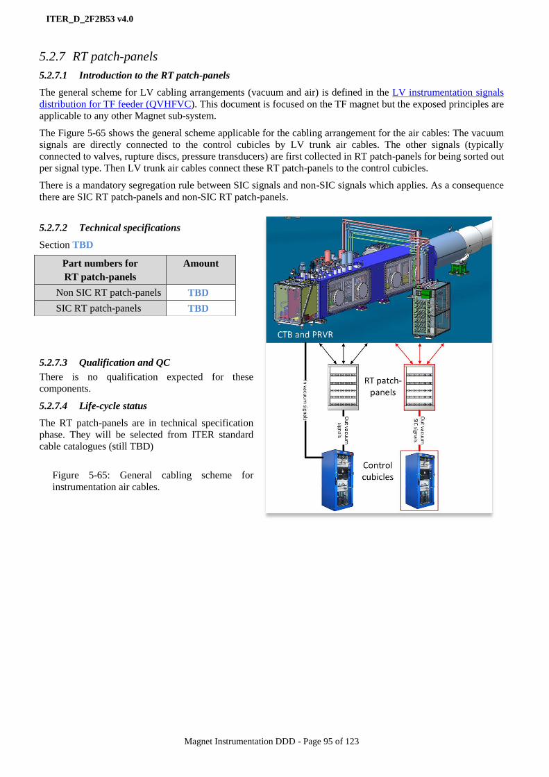
ITER_D_2F2B53 v4.0
Magnet Instrumentation DDD - Page 95 of 123
5.2.7 RT patch-panels
5.2.7.1 Introduction to the RT patch-panels
The general scheme for LV cabling arrangements (vacuum and air) is defined in the LV instrumentation signals
distribution for TF feeder (QVHFVC). This document is focused on the TF magnet but the exposed principles are
applicable to any other Magnet sub-system.
The Figure 5-65 shows the general scheme applicable for the cabling arrangement for the air cables: The vacuum
signals are directly connected to the control cubicles by LV trunk air cables. The other signals (typically
connected to valves, rupture discs, pressure transducers) are first collected in RT patch-panels for being sorted out
per signal type. Then LV trunk air cables connect these RT patch-panels to the control cubicles.
There is a mandatory segregation rule between SIC signals and non-SIC signals which applies. As a consequence
there are SIC RT patch-panels and non-SIC RT patch-panels.
5.2.7.2 Technical specifications
Section TBD
5.2.7.3 Qualification and QC
There is no qualification expected for these
components.
5.2.7.4 Life-cycle status
The RT patch-panels are in technical specification
phase. They will be selected from ITER standard
cable catalogues (still TBD)
Figure 5-65: General cabling scheme for
instrumentation air cables.
Part numbers for
RT patch-panels
Amount
Non SIC RT patch-panels TBD
SIC RT patch-panels TBD

ITER_D_2F2B53 v4.0
Magnet Instrumentation DDD - Page 96 of 123
5.2.8 Rogowski coils
5.2.8.1 Introduction to Rogowski coils
From the quench detection scheme selected for the PF and CS
Magnets see the section 4.5, dI/dt measurements are required for
performing the MIK compensation prior to the quench detection. The
efficient way to get the dI/dt is to introduce Rogowski coils in the
path of the power busbars. The appropriate location is today still
TBD.
Figure 5-66: Illustration of Rogowski coil, courtesy of NFRI -
KSTAR
5.2.8.2 Technical specifications
Section TBD
5.2.8.3 Qualification and QC
Section TBD
5.2.8.4 Life-cycle status
The Rogowski coils are in technical specification phase.
Part numbers for Rogowski coils Amount
Magnet Rogowski coil TBD

ITER_D_2F2B53 v4.0
Magnet Instrumentation DDD - Page 97 of 123
5.3 Thermo-mechanical instrumentation component families
The thermo-mechanical instrumentation requirements are expressed in the section 4.6. From these requirements
displacement, strain, and temperature measurements implemented by electrical and optical based technologies are
required to monitor the Magnet structures.
The LV T measurement solution as introduced in the section 5.2.1 answers the electrical temperature
measurement requirement, below sections elaborate on other measurement solutions.
The thermo-mechanical instrumentation will be installed on ITER site at the time the Magnet mechanical
structures will be. The protection of these fragile components during the installation phase is then an important
point to pay a particular attention.
These thermo-mechanical measurements are quasi-static in term of sampling rate and require a precision better
than 10% of the measured value.
5.3.1 LV displacement sensors and conditioner
5.3.1.1 Introduction to LV displacement sensors
Capacitive and resistive potentiometers based technologies from COTS products were initially considered. For
cost containment the selected solution is the resistive potentiometer technology. The measurement principle is
simple: For long measurement span (e.g. busbar S-bend, CS height) there are two supports fixed on the two
structure elements the displacement to monitor; cable is fixed on one support at one end and the other cable end is
connected to a displacement sensor. For short span (e.g. PF) there is a direct contact of the sensor rod.
Figure 5-67: Illustration of LV displacement sensor and
support
Figure 5-68: Illustration of LV displacement sensor
location in feeders to monitor the thermal
contraction of the busbars
5.3.1.2 Technical specifications: the sensor
The sensor range is 0 to 100 mm with a precision better than 1 mm.
The linearity of the potentiometer is better than 2% of the full range.
The resistance material has a low temperature coefficient.
The maximum power dissipated by the potentiometer is below 0.5 Watts.
The sensors are delivered with a voltage insulated support, a 6 wire signal cable already
connected and equipped with an insulated shaft.
5.3.1.3 Technical specifications: the signal conditioner
The measurement of the resistances is AC using a carrier frequency. The signal readout is EMI
noise insensitive (noise level less than 1% of the true signal).
The signal sampling rate around 10 s.
The conditioner/controller interface is implemented with the PROFIBUS protocol.
Conditioners delivered in 19”chassis ready for integration in standard ITER I&C cubicles.
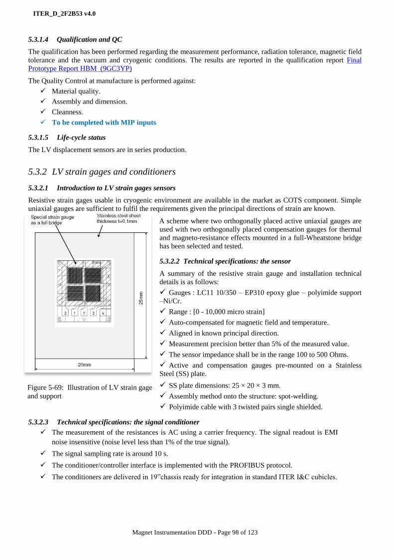
ITER_D_2F2B53 v4.0
Magnet Instrumentation DDD - Page 98 of 123
5.3.1.4 Qualification and QC
The qualification has been performed regarding the measurement performance, radiation tolerance, magnetic field
tolerance and the vacuum and cryogenic conditions. The results are reported in the qualification report Final
Prototype Report HBM (9GC3YP)
The Quality Control at manufacture is performed against:
Material quality.
Assembly and dimension.
Cleanness.
To be completed with MIP inputs
5.3.1.5 Life-cycle status
The LV displacement sensors are in series production.
5.3.2 LV strain gages and conditioners
5.3.2.1 Introduction to LV strain gages sensors
Resistive strain gages usable in cryogenic environment are available in the market as COTS component. Simple
uniaxial gauges are sufficient to fulfil the requirements given the principal directions of strain are known.
A scheme where two orthogonally placed active uniaxial gauges are
used with two orthogonally placed compensation gauges for thermal
and magneto-resistance effects mounted in a full-Wheatstone bridge
has been selected and tested.
5.3.2.2 Technical specifications: the sensor
A summary of the resistive strain gauge and installation technical
details is as follows:
Gauges : LC11 10/350 – EP310 epoxy glue – polyimide support
–Ni/Cr.
Range : [0 - 10,000 micro strain]
Auto-compensated for magnetic field and temperature.
Aligned in known principal direction.
Measurement precision better than 5% of the measured value.
The sensor impedance shall be in the range 100 to 500 Ohms.
Active and compensation gauges pre-mounted on a Stainless
Steel (SS) plate.
SS plate dimensions: 25 × 20 × 3 mm.
Assembly method onto the structure: spot-welding.
Polyimide cable with 3 twisted pairs single shielded.
5.3.2.3 Technical specifications: the signal conditioner
The measurement of the resistances is AC using a carrier frequency. The signal readout is EMI
noise insensitive (noise level less than 1% of the true signal).
The signal sampling rate is around 10 s.
The conditioner/controller interface is implemented with the PROFIBUS protocol.
The conditioners are delivered in 19”chassis ready for integration in standard ITER I&C cubicles.
Figure 5-69: Illustration of LV strain gage
and support
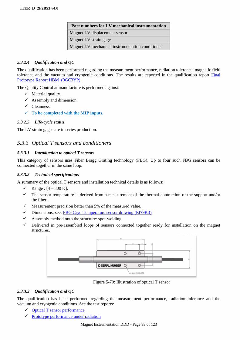
ITER_D_2F2B53 v4.0
Magnet Instrumentation DDD - Page 99 of 123
5.3.2.4 Qualification and QC
The qualification has been performed regarding the measurement performance, radiation tolerance, magnetic field
tolerance and the vacuum and cryogenic conditions. The results are reported in the qualification report Final
Prototype Report HBM (9GC3YP)
The Quality Control at manufacture is performed against:
Material quality.
Assembly and dimension.
Cleanness.
To be completed with the MIP inputs.
5.3.2.5 Life-cycle status
The LV strain gages are in series production.
5.3.3 Optical T sensors and conditioners
5.3.3.1 Introduction to optical T sensors
This category of sensors uses Fiber Bragg Grating technology (FBG). Up to four such FBG sensors can be
connected together in the same loop.
5.3.3.2 Technical specifications
A summary of the optical T sensors and installation technical details is as follows:
Range : [4 – 300 K].
The sensor temperature is derived from a measurement of the thermal contraction of the support and/or
the fiber.
Measurement precision better than 5% of the measured value.
Dimensions, see: FBG Cryo Temperature sensor drawing (PJ79K3)
Assembly method onto the structure: spot-welding.
Delivered in pre-assembled loops of sensors connected together ready for installation on the magnet
structures.
Figure 5-70: Illustration of optical T sensor
5.3.3.3 Qualification and QC
The qualification has been performed regarding the measurement performance, radiation tolerance and the
vacuum and cryogenic conditions. See the test reports:
Optical T sensor performance
Prototype performance under radiation
Part numbers for LV mechanical instrumentation
Magnet LV displacement sensor
Magnet LV strain gage
Magnet LV mechanical instrumentation conditioner

ITER_D_2F2B53 v4.0
Magnet Instrumentation DDD - Page 100 of 123
The Quality Control at manufacture is performed against:
Material quality.
Assembly and dimension.
Thermal cycle and spectral validation.
Cleanness.
Calibration and operation (conditioners)
5.3.3.4 Life-cycle status
The optical T sensors are in series production.
5.3.4 Optical displacement sensors and conditioners
5.3.4.1 Introduction to optical displacement sensors
This category of sensors uses Fiber Bragg Grating (FBG) and Fabry-Perot (FP) technologies. Up to four such
FBG sensors can be connected together in the same loop.
There are three displacement ranges required to fulfil the Magnet structure requirements.
5.3.4.2 Technical specifications
A summary of the optical displacement sensor and installation technical details is as follows:
Ranges :
• [0 – 6 mm] FBG
• [0 – 40 mm] FP
• [0 – 80 mm] FBG
Measurement precision better than 5% of the measured value.
Dimensions:
• FBG Cryo Displacement sensor 3mm drawing
• FP Cryo large Displacement sensor 40 mm drawing
• FBG Cryo large Displacement sensor 80 mm drawing
Assembly method onto the structure: spot-welding.
Delivered in pre-assembled loops of sensors connected together ready for installation on the magnet
structures.
Figure 5-71: Illustration of optical displacement sensor (left 40 mm range FP, right 3 mm range FBG)
5.3.4.3 Qualification and QC
The qualification has been performed regarding the measurement performance, radiation tolerance and the
vacuum and cryogenic conditions. See the test reports:
Displacement Sensor performance at 5.5K
Prototype performance FBG under radiation

ITER_D_2F2B53 v4.0
Magnet Instrumentation DDD - Page 101 of 123
The Quality Control at manufacture is performed against:
Material quality.
Assembly and dimension.
Thermal cycle and spectral validation
Cleanness.
Calibration and operation (conditioners only)
5.3.4.4 Life-cycle status
The optical displacement sensors are in series production.
5.3.5 Optical strain gages and conditioners
5.3.5.1 Introduction to optical strain gages
This sensor category of sensors uses Fiber Bragg Grating technology. Up to three such sensors can be connected
together in the same loop.
5.3.5.2 Technical specifications
A summary of the optical T sensors and installation technical details is as follows:
Range: [0 – 10,000 microstrain]
Auto-compensated for temperature.
Measurement precision better than 5% of the measured value.
Dimensions: see the FBG Cryo Strain sensor drawing
Assembly method onto the structure: spot-welding.
Delivered in pre-assembled loops of sensors connected together ready for installation on the magnet
structures.
Figure 5-72: Illustration of
optical strain gage
5.3.5.3 Qualification and QC
The qualification has been performed regarding the measurement performance, radiation tolerance and the
vacuum and cryogenic conditions. See the test reports:
Strain Sensor Prototype Performance at 5.5K
Prototype performance FBG under radiation
The Quality Control at manufacture is performed against:
Material quality.
Assembly and dimension.
Thermal cycle and spectral validation
Cleanness.
Calibration and operation (conditioners only)
5.3.5.4 Life-cycle status
The optical strain gages are in series production.
ITER_D_2F2B53 v4.0
Magnet Instrumentation DDD - Page 102 of 123
5.3.6 Fiber optic cables for optical instrumentation
5.3.6.1 Introduction to fiber optic cables for optical instrumentation
They are the optic cables used for connecting together the optical instrumentation sensors assembled in sensor
loops connected to optical patch-panels and further to optical feedthroughs through bundles of cables.
5.3.6.2 Technical specifications
Glass Fiber (single-mode or Multi-mode): 125 ±2 microns diameter
• Polyimide coating (cryogenic fiber protection function)
• Epoxy acrylate buffer (softer material to mechanically uncouple fibre and PEEK and facilitate
stripping)
• PEEK coating (outside mechanical protection function, vacuum-facing)
Bundle of 6 optical fibers:
• PEEK coated fibers placed around Kevlar core to form hexagon.
• Central core of Kevlar yarns.
• PEEK fibers wound with "double open spiral" shape around core.
• Bundle to be wound with open Kapton tape (no gluing, no welding, no re-polymerization)
Bundle of 42 optical fibers:
• Produced by assembling 7 bundles of 6 fibers each (see above)
• 7 fibers bundles wound with "double open spiral" shape.
5.3.6.3 Qualification and QC
The qualification has been performed regarding the measurement performance, radiation tolerance and the
vacuum and cryogenic conditions. See the test report: Fiber Optic Cable Prototype Performance (6LFL85)
5.3.6.4 Life-cycle status
The fiber optic cables are in series production.
Part numbers for Optical mechanical instrumentation
Magnet OPT FP displacement sensor
Magnet OPT FGB displacement sensor
Magnet OPT FBG large displacement sensor
Magnet OPT FBG strain gage
Magnet OPT FBG T sensor
Magnet Optical FBG instrumentation conditioner
Magnet Optical FP instrumentation conditioner
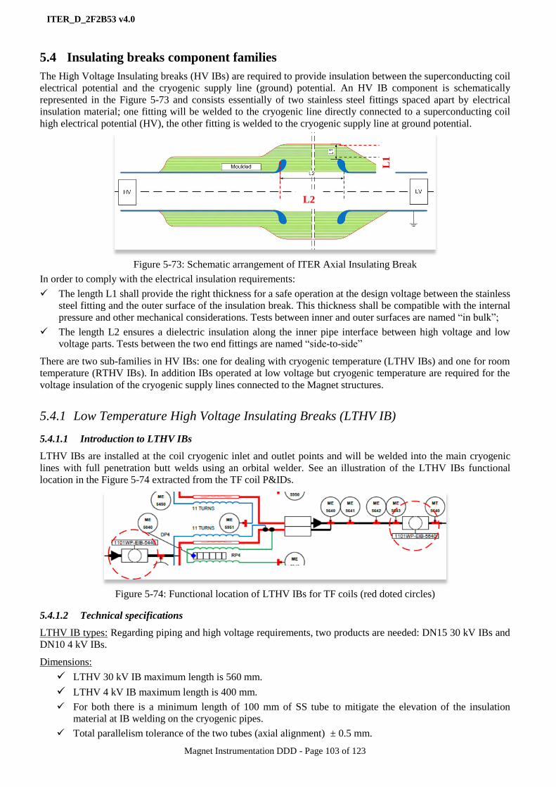
ITER_D_2F2B53 v4.0
Magnet Instrumentation DDD - Page 103 of 123
5.4 Insulating breaks component families
The High Voltage Insulating breaks (HV IBs) are required to provide insulation between the superconducting coil
electrical potential and the cryogenic supply line (ground) potential. An HV IB component is schematically
represented in the Figure 5-73 and consists essentially of two stainless steel fittings spaced apart by electrical
insulation material; one fitting will be welded to the cryogenic line directly connected to a superconducting coil
high electrical potential (HV), the other fitting is welded to the cryogenic supply line at ground potential.
Figure 5-73: Schematic arrangement of ITER Axial Insulating Break
In order to comply with the electrical insulation requirements:
The length L1 shall provide the right thickness for a safe operation at the design voltage between the stainless
steel fitting and the outer surface of the insulation break. This thickness shall be compatible with the internal
pressure and other mechanical considerations. Tests between inner and outer surfaces are named “in bulk”;
The length L2 ensures a dielectric insulation along the inner pipe interface between high voltage and low
voltage parts. Tests between the two end fittings are named “side-to-side”
There are two sub-families in HV IBs: one for dealing with cryogenic temperature (LTHV IBs) and one for room
temperature (RTHV IBs). In addition IBs operated at low voltage but cryogenic temperature are required for the
voltage insulation of the cryogenic supply lines connected to the Magnet structures.
5.4.1 Low Temperature High Voltage Insulating Breaks (LTHV IB)
5.4.1.1 Introduction to LTHV IBs
LTHV IBs are installed at the coil cryogenic inlet and outlet points and will be welded into the main cryogenic
lines with full penetration butt welds using an orbital welder. See an illustration of the LTHV IBs functional
location in the Figure 5-74 extracted from the TF coil P&IDs.
Figure 5-74: Functional location of LTHV IBs for TF coils (red doted circles)
5.4.1.2 Technical specifications
LTHV IB types: Regarding piping and high voltage requirements, two products are needed: DN15 30 kV IBs and
DN10 4 kV IBs.
Dimensions:
LTHV 30 kV IB maximum length is 560 mm.
LTHV 4 kV IB maximum length is 400 mm.
For both there is a minimum length of 100 mm of SS tube to mitigate the elevation of the insulation
material at IB welding on the cryogenic pipes.
Total parallelism tolerance of the two tubes (axial alignment) ± 0.5 mm.
L1
L2

ITER_D_2F2B53 v4.0
Magnet Instrumentation DDD - Page 104 of 123
Materials:
Stainless steel pipe: AISI 316L.
Insulating material: shall be radiation tolerant and boron free.
Performance specifications: They are specified in the Table 43 for the electrical requirements, in the Table 44 for
the mechanical requirements and in the Table 45 for the other requirements.
Item Voltage requirements Qualification criteria
30 kV LTHV IBs
Rated voltage 30 kV DC Pure He gas
Leakage current < 15 µ𝐴 Test voltage 56 kV DC
Paschen discharge 30 kV AC < 5 pC
4 kV LTHV IBs
Rated voltage 4 kV DC Pure He gas
Leakage current < 6 µ𝐴 Test voltage 8 kV DC
Paschen discharge 4 kV AC < 5 pC
Table 43: Electrical performance requirements for the LTHV IBs
Item Requirement
30 kV LTHV IBs 4 kV LTHV IBs
Vacuum leak tightness Leak rate < 10-9
Pa m3/s Leak rate < 10-9
Pa m3/s
Rated pressure 30 bars 15 bars
Test Pressure 39 15
bars (RT and 77 K) 19.5 bars (RT and 77 K)
Thermal cycle [77 K 300 K] 50 cycles [77 K 300 K] 50 cycles
Bending test 100 Nm - (RT and 77 K) 15 Nm - (RT and 77 K)
Torsion test
Tension/compression 2 kN - (RT and 77 K) 1 kN (RT and 77 K)
Table 44: Mechanical performance requirements for the LTHV IBs
Item Requirement
Operating temperature range [4 K 300 K]
Lifetime > 20 years
Table 45: Other requirements for the LTHV IBs
Table 46: LTHV IB quantities per type
Figure 5-75: Illustration of LTHV 30 kV IB
15
Type tests are performed by IO @ 42 bars
LTHV IBs part numbers Amount
Magnet LTHV 30 kV IB 1000
Magnet LTHV 4 kV IB 400
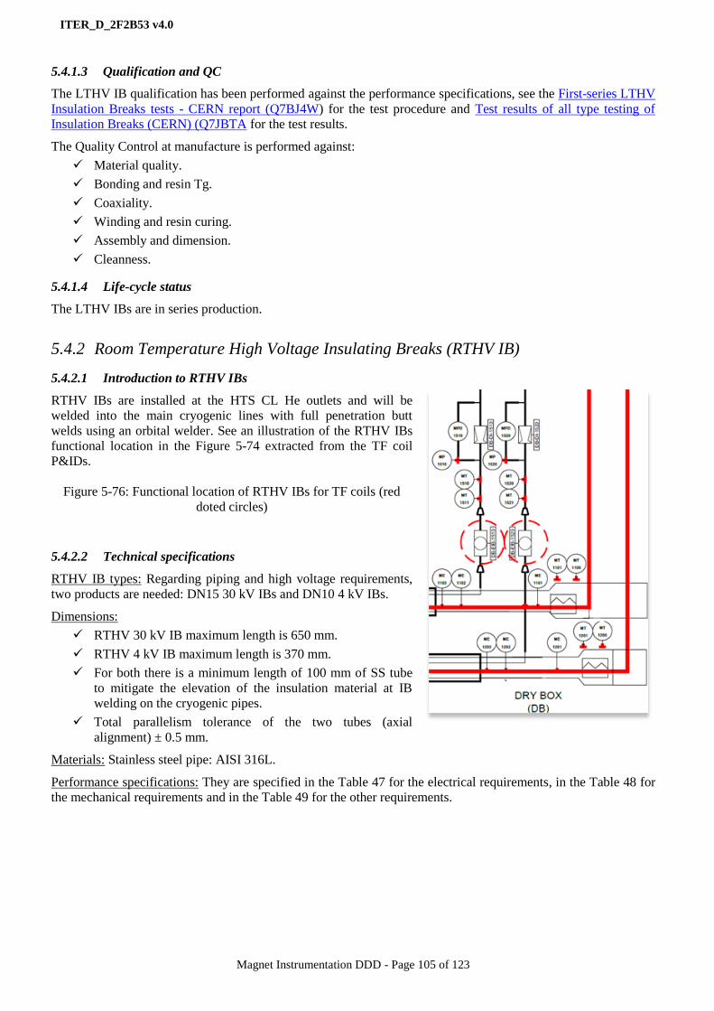
ITER_D_2F2B53 v4.0
Magnet Instrumentation DDD - Page 105 of 123
5.4.1.3 Qualification and QC
The LTHV IB qualification has been performed against the performance specifications, see the First-series LTHV
Insulation Breaks tests - CERN report (Q7BJ4W) for the test procedure and Test results of all type testing of
Insulation Breaks (CERN) (Q7JBTA for the test results.
The Quality Control at manufacture is performed against:
Material quality.
Bonding and resin Tg.
Coaxiality.
Winding and resin curing.
Assembly and dimension.
Cleanness.
5.4.1.4 Life-cycle status
The LTHV IBs are in series production.
5.4.2 Room Temperature High Voltage Insulating Breaks (RTHV IB)
5.4.2.1 Introduction to RTHV IBs
RTHV IBs are installed at the HTS CL He outlets and will be
welded into the main cryogenic lines with full penetration butt
welds using an orbital welder. See an illustration of the RTHV IBs
functional location in the Figure 5-74 extracted from the TF coil
P&IDs.
Figure 5-76: Functional location of RTHV IBs for TF coils (red
doted circles)
5.4.2.2 Technical specifications
RTHV IB types: Regarding piping and high voltage requirements,
two products are needed: DN15 30 kV IBs and DN10 4 kV IBs.
Dimensions:
RTHV 30 kV IB maximum length is 650 mm.
RTHV 4 kV IB maximum length is 370 mm.
For both there is a minimum length of 100 mm of SS tube
to mitigate the elevation of the insulation material at IB
welding on the cryogenic pipes.
Total parallelism tolerance of the two tubes (axial
alignment) ± 0.5 mm.
Materials: Stainless steel pipe: AISI 316L.
Performance specifications: They are specified in the Table 47 for the electrical requirements, in the Table 48 for
the mechanical requirements and in the Table 49 for the other requirements.
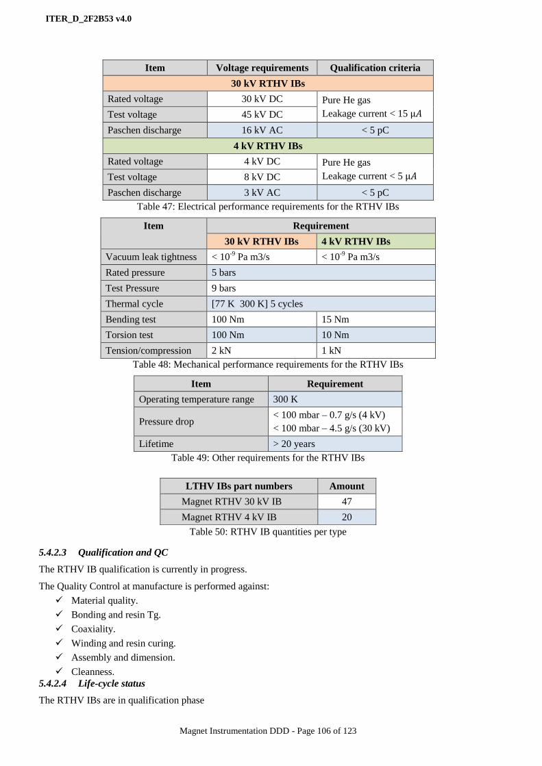
ITER_D_2F2B53 v4.0
Magnet Instrumentation DDD - Page 106 of 123
Item Voltage requirements Qualification criteria
30 kV RTHV IBs
Rated voltage 30 kV DC Pure He gas
Leakage current < 15 µ𝐴 Test voltage 45 kV DC
Paschen discharge 16 kV AC < 5 pC
4 kV RTHV IBs
Rated voltage 4 kV DC Pure He gas
Leakage current < 5 µ𝐴 Test voltage 8 kV DC
Paschen discharge 3 kV AC < 5 pC
Table 47: Electrical performance requirements for the RTHV IBs
Item Requirement
30 kV RTHV IBs 4 kV RTHV IBs
Vacuum leak tightness < 10-9
Pa m3/s < 10-9
Pa m3/s
Rated pressure 5 bars
Test Pressure 9 bars
Thermal cycle [77 K 300 K] 5 cycles
Bending test 100 Nm 15 Nm
Torsion test 100 Nm 10 Nm
Tension/compression 2 kN 1 kN
Table 48: Mechanical performance requirements for the RTHV IBs
Item Requirement
Operating temperature range 300 K
Pressure drop < 100 mbar – 0.7 g/s (4 kV)
< 100 mbar – 4.5 g/s (30 kV)
Lifetime > 20 years
Table 49: Other requirements for the RTHV IBs
Table 50: RTHV IB quantities per type
5.4.2.3 Qualification and QC
The RTHV IB qualification is currently in progress.
The Quality Control at manufacture is performed against:
Material quality.
Bonding and resin Tg.
Coaxiality.
Winding and resin curing.
Assembly and dimension.
Cleanness.
5.4.2.4 Life-cycle status
The RTHV IBs are in qualification phase
LTHV IBs part numbers Amount
Magnet RTHV 30 kV IB 47
Magnet RTHV 4 kV IB 20
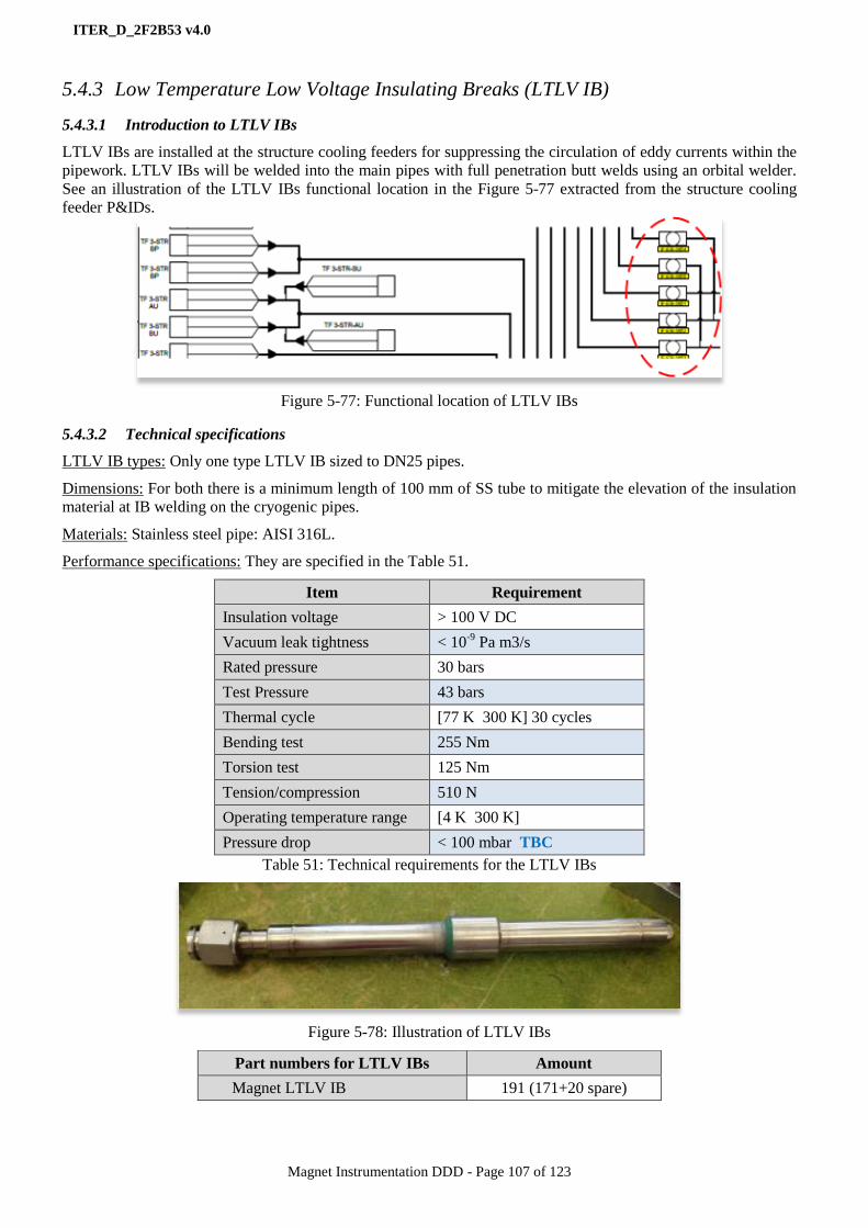
ITER_D_2F2B53 v4.0
Magnet Instrumentation DDD - Page 107 of 123
5.4.3 Low Temperature Low Voltage Insulating Breaks (LTLV IB)
5.4.3.1 Introduction to LTLV IBs
LTLV IBs are installed at the structure cooling feeders for suppressing the circulation of eddy currents within the
pipework. LTLV IBs will be welded into the main pipes with full penetration butt welds using an orbital welder.
See an illustration of the LTLV IBs functional location in the Figure 5-77 extracted from the structure cooling
feeder P&IDs.
Figure 5-77: Functional location of LTLV IBs
5.4.3.2 Technical specifications
LTLV IB types: Only one type LTLV IB sized to DN25 pipes.
Dimensions: For both there is a minimum length of 100 mm of SS tube to mitigate the elevation of the insulation
material at IB welding on the cryogenic pipes.
Materials: Stainless steel pipe: AISI 316L.
Performance specifications: They are specified in the Table 51.
Item Requirement
Insulation voltage > 100 V DC
Vacuum leak tightness < 10-9
Pa m3/s
Rated pressure 30 bars
Test Pressure 43 bars
Thermal cycle [77 K 300 K] 30 cycles
Bending test 255 Nm
Torsion test 125 Nm
Tension/compression 510 N
Operating temperature range [4 K 300 K]
Pressure drop < 100 mbar TBC
Table 51: Technical requirements for the LTLV IBs
Figure 5-78: Illustration of LTLV IBs
Part numbers for LTLV IBs Amount
Magnet LTLV IB 191 (171+20 spare)

ITER_D_2F2B53 v4.0
Magnet Instrumentation DDD - Page 108 of 123
5.4.3.3 Qualification and QC
The LTHV IB qualification is currently in progress.
The Quality Control at manufacture is performed against:
Material quality.
Bonding and resin Tg.
Coaxiality.
Winding and resin curing.
Assembly and dimension.
Pressure leak.
Thermal cycle.
Cleanness.
5.4.3.4 Life-cycle status
The LTLV IBs are in qualification phase
5.5 Valves component families
This family is made of different components which are part of the CTBs, SCVBs and auxiliaries (PRVR),
involved in cryogenic control and protection functions. These components are I&C related since generators and
consumers of I&C signals and as such are connected to the Magnet I&C system. By extension of scope and for
convenience other components as burst discs and pumps are also considered in this family.
These components are identified in the Table 52; they are technically specified by IO-CT but procured by CNDA.
The document Inventory of Feeder Cryogenic Valves and Components in the PRVR (6NWKGP) provides the
detailed list of them.
The 3-way valves, purge valves and vacuum pumps are not mentioned because manually controlled and not
monitored by the Magnet I&C system (a design option there).
The interface schemes of these valve components with the Magnet I&C system are given in the sections 4.7.6 and
4.7.8 and much more detailed in the DDD11-10: Magnet Controls (JF2N9W).
The technical specifications of the valve components are elaborated in the following documents:
Technical Specification for the Cryogenic Valves for the ITER Magnets 9FXE9U
Technical Specification for the Cryogenic Quench Valves AW5MJB
Technical Specification for the Pressure Relief Valves B8BGXF
Technical Specification for the Burst Discs for the ITER Magnets AVY46Q
Part number Amount
Magnet control valves (cold and RT) 385
Magnet quench valves 115
Magnet pressure relief valves 110
Magnet burst discs 115
Table 52: Valve components and amounts

ITER_D_2F2B53 v4.0
Magnet Instrumentation DDD - Page 109 of 123
6 Work flow from component technical specifications to deliverables
6.1 Workflow overview
From the Magnet instrumentation component life-cycle scheme presented in the chapter 4.13, the next step after
the definition of the technical specifications is the Call for Tender for manufacture.
The details of the IO-CT procedure for tendering and contract placing are out of scope of this DDD and then will
be skipped to jump directly to the manufacture contract management.
6.1.1 Procurement contract management
The Magnet instrumentation component procurement strategy is summarized in the chapter 4.12. For the
contracts mentioned in the Table 8 and placed by IO-CT the following rules apply on contract management:
The contract technical matters as technical specifications, supplier technical offer assessments, … are
placed under the responsibility of a contract technical RO from the IO-CT Magnet division.
The contract non-technical matters as financial offer assessment, liabilities,… are placed under the
responsibility of a contract procurement RO from the IO-CT Procurement division.
IO-CT procurement contracts are deliverable based.
The Magnet instrumentation procurement contracts are split in several phases: design and if required
prototyping – design approval / prototype qualification – first of series production – first of series
qualification – series production – delivery and acceptance. Hold points for go/no-go are introduced at
qualification.
IO-CT keeps responsible for the component qualification process and criteria and for the deliverable
acceptance.
The contract technical, QA and QC materials are stored in dedicated IDM folders and MMD with the
appropriate access rights and Non-Disclosure Agreements signed (NDA). Tracking features are
implemented by MMD.
6.2 Manufacture
6.2.1 Procurement contract QA and QC management
Regarding QA and QC management the following rules apply:
The contract QA matters as Quality Plans, Quality Requirements, … are submitted to the approval of a
QA RO of the QA IO-CT division.
Manufacture Quality Control (QC) is formalized by a Manufacture and Inspection Plan (MIP). The MIP
is proposed by the supplier and approved by the IO-CT contract technical RO and the QA RO for each
manufacturing phase of the contract.
Inspection at supplier manufacture plant can be performed by IO-CT at any phase of the manufacture.
The following IO-CT QA reference documents apply:
• ITER Procurement Quality Requirements (22MFG4).
• MQP Deviations and Non Conformities (22F53X)
• Quality Plan (22MFMW)
• Manufacturing and Inspection Plan (22MDZD)
6.2.2 Scope of the IO-CT contract technical RO
The IO-CT contract technical RO is in charge of the following tasks:
The definition of the technical specifications from draft to final versions.
The interface with the contract procurement RO for supplier selection and contract placing.
The technical interface with the supplier.
The review/approval of QA/QC documentation and procedures (MIP).
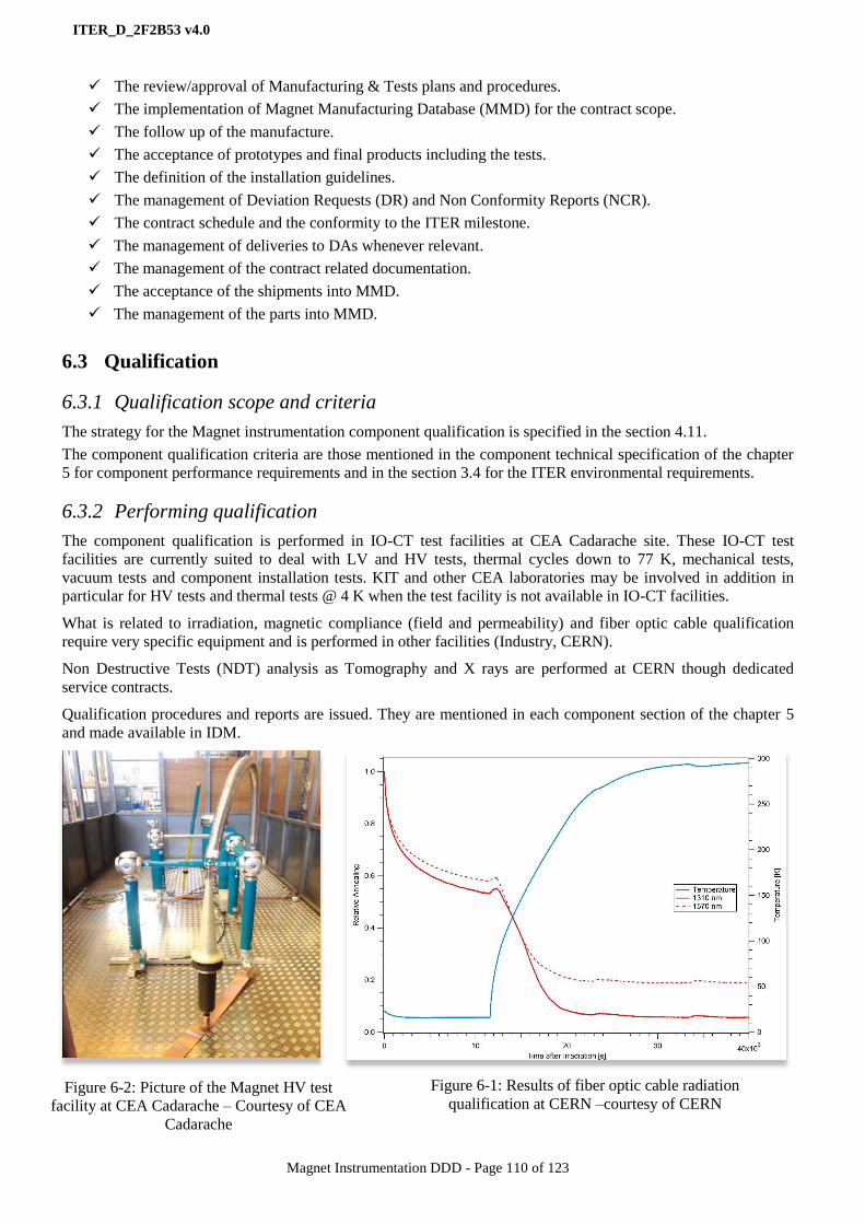
ITER_D_2F2B53 v4.0
Magnet Instrumentation DDD - Page 110 of 123
The review/approval of Manufacturing & Tests plans and procedures.
The implementation of Magnet Manufacturing Database (MMD) for the contract scope.
The follow up of the manufacture.
The acceptance of prototypes and final products including the tests.
The definition of the installation guidelines.
The management of Deviation Requests (DR) and Non Conformity Reports (NCR).
The contract schedule and the conformity to the ITER milestone.
The management of deliveries to DAs whenever relevant.
The management of the contract related documentation.
The acceptance of the shipments into MMD.
The management of the parts into MMD.
6.3 Qualification
6.3.1 Qualification scope and criteria
The strategy for the Magnet instrumentation component qualification is specified in the section 4.11.
The component qualification criteria are those mentioned in the component technical specification of the chapter
5 for component performance requirements and in the section 3.4 for the ITER environmental requirements.
6.3.2 Performing qualification
The component qualification is performed in IO-CT test facilities at CEA Cadarache site. These IO-CT test
facilities are currently suited to deal with LV and HV tests, thermal cycles down to 77 K, mechanical tests,
vacuum tests and component installation tests. KIT and other CEA laboratories may be involved in addition in
particular for HV tests and thermal tests @ 4 K when the test facility is not available in IO-CT facilities.
What is related to irradiation, magnetic compliance (field and permeability) and fiber optic cable qualification
require very specific equipment and is performed in other facilities (Industry, CERN).
Non Destructive Tests (NDT) analysis as Tomography and X rays are performed at CERN though dedicated
service contracts.
Qualification procedures and reports are issued. They are mentioned in each component section of the chapter 5
and made available in IDM.
Figure 6-2: Picture of the Magnet HV test
facility at CEA Cadarache – Courtesy of CEA
Cadarache
Figure 6-1: Results of fiber optic cable radiation
qualification at CERN –courtesy of CERN

ITER_D_2F2B53 v4.0
Magnet Instrumentation DDD - Page 111 of 123
6.4 Quality Control
6.4.1 QC scope and implementation
The manufacture Quality Control scope is defined in the component technical specifications of the chapter 5 for
each component.
The details of QC points are formalised in MIPs. As expressed in the section 6.2.1, there is a MIP defined for
each component and each contract manufacture phase.
The details of the QC implementation are specified in supplier manufacture procedures. These supplier
procedures are not delivered to IO-CT but shall be referenced clearly in the MIPs and can be checked by IO-CT at
manufacturer inspection.
Figure 6-5: Illustration of MIP for the CWT production
Figure 6-4: Picture of the LV T sensor test
facility –courtesy of CEA SBT
Figure 6-3: Picture of optical sensor test
facility @ 4K –courtesy of CEA SBT

ITER_D_2F2B53 v4.0
Magnet Instrumentation DDD - Page 112 of 123
6.5 Delivering
6.5.1 What to deliver, to whom and when
The delivery process introduces the concept of “part”. A “part” is a one manufactured element. The contract
deliverables are splits in batches; there may be different part types in scope of a procurement contract and many
parts in one delivery batch.
The definition of the batch contents and due dates are specified in the contract technical specifications but
discussed and updated at the procurement contract Kick-Off Meeting.
After manufacture the parts are routed from supplier manufacture plants to end-users as illustrated in the Figure
6-6. This routing model assumes the components are shipped first to the Magnet storage site close to the ITER
construction site for being inspected by IO-CT, for temporary storage and qualification purpose depending on the
contract phase. There is no direct shipment from the supplier manufacture plant to any end-users (save IO-CT).
From that Magnet storage some parts are shipped to end-users: Magnet PA suppliers (DA contractors) where the
components are involved in a Magnet procurement. The parts left are kept stored into the IO-CT storage waiting
for installation to the Magnet system at Magnet assembly on the ITER construction site.
The definition of what to deliver to DAs has been defined from the Magnet P&IDs (see the section 4.3)
depending on the Procurement Arrangement (PA) scope and formally agreed through PA Deviation Requests
(DR). The repository of these DR materials is there.
The definition of when is defined and kept update though schedule IPLs.
Figure 6-6: Magnet instrumentation routing model
6.5.2 Delivery process
The document Management of shipments for Magnet instrumentation (PVGADE) defines the details of the
Magnet instrumentation shipment process and workflow. The picture of the workflow is shown in the Figure 6-7.
Figure 6-7: Picture of the Magnet instrumentation shipment work-flow
Instrumentation supplier site
Magnet storage site
Magnet lab site
Procurement supplier site /
DA site
ITER construction
site
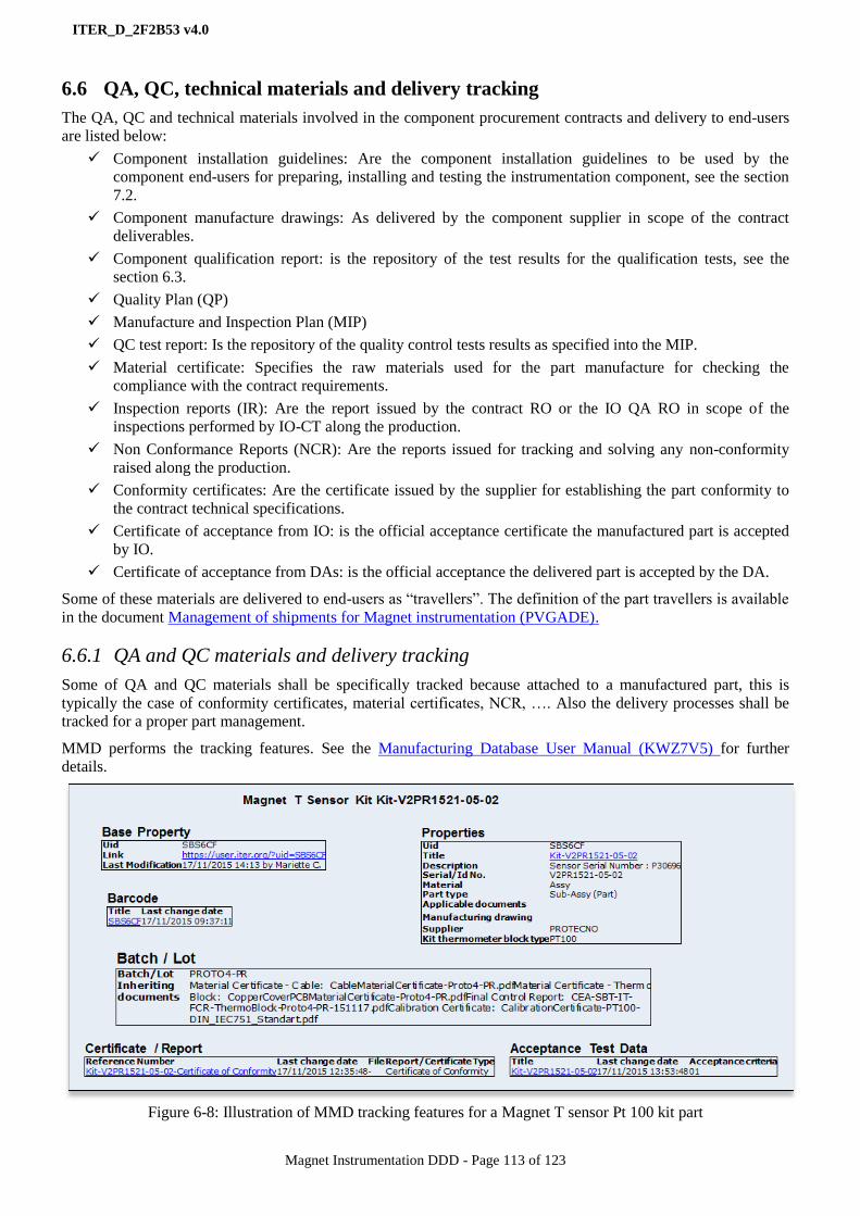
ITER_D_2F2B53 v4.0
Magnet Instrumentation DDD - Page 113 of 123
6.6 QA, QC, technical materials and delivery tracking
The QA, QC and technical materials involved in the component procurement contracts and delivery to end-users
are listed below:
Component installation guidelines: Are the component installation guidelines to be used by the
component end-users for preparing, installing and testing the instrumentation component, see the section
7.2.
Component manufacture drawings: As delivered by the component supplier in scope of the contract
deliverables.
Component qualification report: is the repository of the test results for the qualification tests, see the
section 6.3.
Quality Plan (QP)
Manufacture and Inspection Plan (MIP)
QC test report: Is the repository of the quality control tests results as specified into the MIP.
Material certificate: Specifies the raw materials used for the part manufacture for checking the
compliance with the contract requirements.
Inspection reports (IR): Are the report issued by the contract RO or the IO QA RO in scope of the
inspections performed by IO-CT along the production.
Non Conformance Reports (NCR): Are the reports issued for tracking and solving any non-conformity
raised along the production.
Conformity certificates: Are the certificate issued by the supplier for establishing the part conformity to
the contract technical specifications.
Certificate of acceptance from IO: is the official acceptance certificate the manufactured part is accepted
by IO.
Certificate of acceptance from DAs: is the official acceptance the delivered part is accepted by the DA.
Some of these materials are delivered to end-users as “travellers”. The definition of the part travellers is available
in the document Management of shipments for Magnet instrumentation (PVGADE).
6.6.1 QA and QC materials and delivery tracking
Some of QA and QC materials shall be specifically tracked because attached to a manufactured part, this is
typically the case of conformity certificates, material certificates, NCR, …. Also the delivery processes shall be
tracked for a proper part management.
MMD performs the tracking features. See the Manufacturing Database User Manual (KWZ7V5) for further
details.
Figure 6-8: Illustration of MMD tracking features for a Magnet T sensor Pt 100 kit part

ITER_D_2F2B53 v4.0
Magnet Instrumentation DDD - Page 114 of 123
Figure 6-9: Illustration of MMD tracking features for shipments
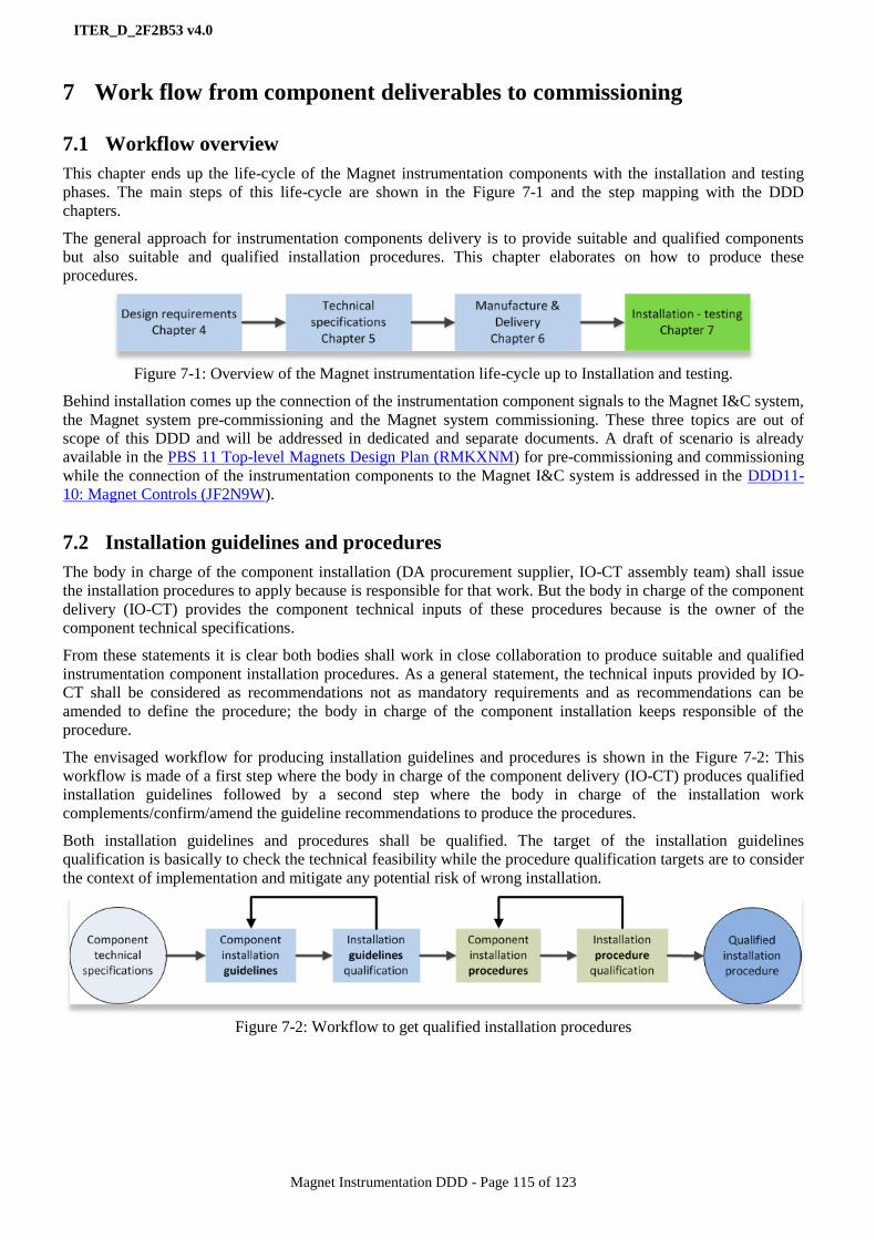
ITER_D_2F2B53 v4.0
Magnet Instrumentation DDD - Page 115 of 123
7 Work flow from component deliverables to commissioning
7.1 Workflow overview
This chapter ends up the life-cycle of the Magnet instrumentation components with the installation and testing
phases. The main steps of this life-cycle are shown in the Figure 7-1 and the step mapping with the DDD
chapters.
The general approach for instrumentation components delivery is to provide suitable and qualified components
but also suitable and qualified installation procedures. This chapter elaborates on how to produce these
procedures.
Figure 7-1: Overview of the Magnet instrumentation life-cycle up to Installation and testing.
Behind installation comes up the connection of the instrumentation component signals to the Magnet I&C system,
the Magnet system pre-commissioning and the Magnet system commissioning. These three topics are out of
scope of this DDD and will be addressed in dedicated and separate documents. A draft of scenario is already
available in the PBS 11 Top-level Magnets Design Plan (RMKXNM) for pre-commissioning and commissioning
while the connection of the instrumentation components to the Magnet I&C system is addressed in the DDD11-
10: Magnet Controls (JF2N9W).
7.2 Installation guidelines and procedures
The body in charge of the component installation (DA procurement supplier, IO-CT assembly team) shall issue
the installation procedures to apply because is responsible for that work. But the body in charge of the component
delivery (IO-CT) provides the component technical inputs of these procedures because is the owner of the
component technical specifications.
From these statements it is clear both bodies shall work in close collaboration to produce suitable and qualified
instrumentation component installation procedures. As a general statement, the technical inputs provided by IO-
CT shall be considered as recommendations not as mandatory requirements and as recommendations can be
amended to define the procedure; the body in charge of the component installation keeps responsible of the
procedure.
The envisaged workflow for producing installation guidelines and procedures is shown in the Figure 7-2: This
workflow is made of a first step where the body in charge of the component delivery (IO-CT) produces qualified
installation guidelines followed by a second step where the body in charge of the installation work
complements/confirm/amend the guideline recommendations to produce the procedures.
Both installation guidelines and procedures shall be qualified. The target of the installation guidelines
qualification is basically to check the technical feasibility while the procedure qualification targets are to consider
the context of implementation and mitigate any potential risk of wrong installation.
Figure 7-2: Workflow to get qualified installation procedures
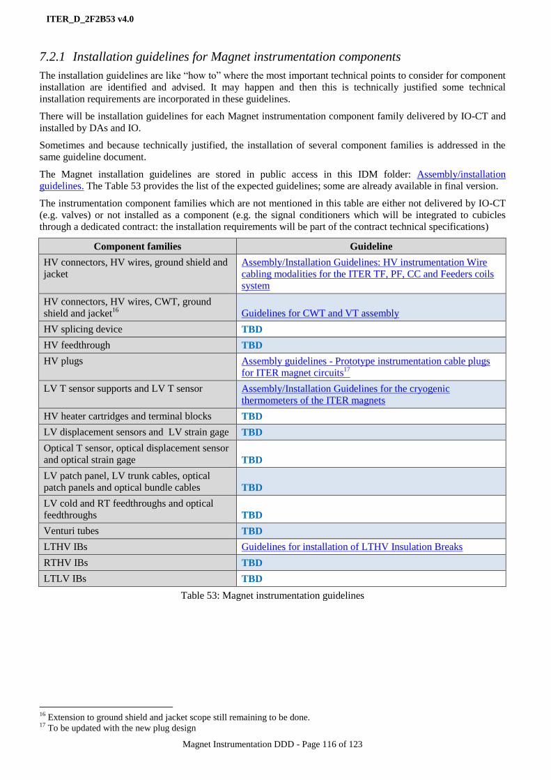
ITER_D_2F2B53 v4.0
Magnet Instrumentation DDD - Page 116 of 123
7.2.1 Installation guidelines for Magnet instrumentation components
The installation guidelines are like “how to” where the most important technical points to consider for component
installation are identified and advised. It may happen and then this is technically justified some technical
installation requirements are incorporated in these guidelines.
There will be installation guidelines for each Magnet instrumentation component family delivered by IO-CT and
installed by DAs and IO.
Sometimes and because technically justified, the installation of several component families is addressed in the
same guideline document.
The Magnet installation guidelines are stored in public access in this IDM folder: Assembly/installation
guidelines. The Table 53 provides the list of the expected guidelines; some are already available in final version.
The instrumentation component families which are not mentioned in this table are either not delivered by IO-CT
(e.g. valves) or not installed as a component (e.g. the signal conditioners which will be integrated to cubicles
through a dedicated contract: the installation requirements will be part of the contract technical specifications)
Component families Guideline
HV connectors, HV wires, ground shield and
jacket
Assembly/Installation Guidelines: HV instrumentation Wire
cabling modalities for the ITER TF, PF, CC and Feeders coils
system
HV connectors, HV wires, CWT, ground
shield and jacket16
Guidelines for CWT and VT assembly
HV splicing device TBD
HV feedthrough TBD
HV plugs Assembly guidelines - Prototype instrumentation cable plugs
for ITER magnet circuits17
LV T sensor supports and LV T sensor Assembly/Installation Guidelines for the cryogenic
thermometers of the ITER magnets
HV heater cartridges and terminal blocks TBD
LV displacement sensors and LV strain gage TBD
Optical T sensor, optical displacement sensor
and optical strain gage TBD
LV patch panel, LV trunk cables, optical
patch panels and optical bundle cables TBD
LV cold and RT feedthroughs and optical
feedthroughs TBD
Venturi tubes TBD
LTHV IBs Guidelines for installation of LTHV Insulation Breaks
RTHV IBs TBD
LTLV IBs TBD
Table 53: Magnet instrumentation guidelines
16
Extension to ground shield and jacket scope still remaining to be done. 17
To be updated with the new plug design
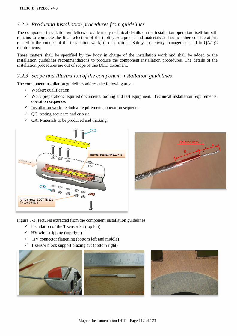
ITER_D_2F2B53 v4.0
Magnet Instrumentation DDD - Page 117 of 123
7.2.2 Producing Installation procedures from guidelines
The component installation guidelines provide many technical details on the installation operation itself but still
remains to complete the final selection of the tooling equipment and materials and some other considerations
related to the context of the installation work, to occupational Safety, to activity management and to QA/QC
requirements.
These matters shall be specified by the body in charge of the installation work and shall be added to the
installation guidelines recommendations to produce the component installation procedures. The details of the
installation procedures are out of scope of this DDD document.
7.2.3 Scope and Illustration of the component installation guidelines
The component installation guidelines address the following area:
Worker: qualification
Work preparation: required documents, tooling and test equipment. Technical installation requirements,
operation sequence.
Installation work: technical requirements, operation sequence.
QC: testing sequence and criteria.
QA: Materials to be produced and tracking.
Figure 7-3: Pictures extracted from the component installation guidelines
Installation of the T sensor kit (top left)
HV wire stripping (top right)
HV connector flattening (bottom left and middle)
T sensor block support brazing cut (bottom right)

ITER_D_2F2B53 v4.0
Magnet Instrumentation DDD - Page 118 of 123
7.2.4 Installation Quality Control
The component installation qualification may identify some potential issues that could jeopardize the performance
or the reliability of the component at operation. These potential issues are duly mentioned in the installation
guidelines with the appropriate QC test and criteria for checking the issue is not met or for mitigating that risk.
The installation procedure shall incorporate these QC tests and criteria. A list of these potential issues already
identified is given in the Table 54.
Component families Potential installation issues
HV connectors, HV wires, ground shield and jacket Lack of electrical continuity of the VT circuit.
Lack of ground insulation.
Wrong wire connection.
Damage to the wire insulation at resin /vacuum interface.
HV connectors, HV wires, CWT, ground shield and
jacket18
As above and in addition the risk of CWT wrinkles at
wrapping.
HV splicing device TBD waiting for the guidelines qualification.
HV feedthrough TBD waiting for the guidelines qualification.
HV plugs Lack of leak tightness.
Damage to the HV cable.
LV T sensor supports and LV T sensor Lack of thermal contact of the T sensor block support.
Damage to the cable/T sensor kit connection.
HV heater cartridges and terminal blocks TBD waiting for the guidelines qualification
LV displacement sensors and LV strain gage TBD waiting for the guidelines qualification
Optical T sensor, optical displacement sensor and
optical strain gage
Damage to the optical fiber
TBD waiting for the guidelines qualification
LV patch panel, LV trunk cables, optical patch
panels and optical bundle cables TBD waiting for the guidelines qualification
LV cold and RT feedthroughs and optical
feedthroughs
Lack of leak tightness.
TBD waiting for the guidelines qualification
Venturi tubes Damage to the pressure taps and capillary tubes
TBD waiting for the guidelines qualification
LTHV IBs Insulation damage from over mechanical load at welding
Insulation damage from over temperature at welding
Introduction of impurity within the IB
Lack of final ground insulation and coating
RTHV IBs Insulation damage from over mechanical load at welding
Insulation damage from over temperature at welding
Introduction of impurity within the IB
Lack of final ground insulation and coating
LTLV IBs Insulation damage from over mechanical load at welding
Insulation damage from over temperature at welding
Introduction of impurity within the IB
Table 54: QC at component installation
18
Extension to ground shield and jacket scope still remaining to be done.

ITER_D_2F2B53 v4.0
Magnet Instrumentation DDD - Page 119 of 123
7.3 Assembly and Inspection Plans (AIP)
7.3.1 AIPs for Magnet instrumentation components
Assembly guidelines and procedures are technical materials for specifying technical work. In addition and for
resource and schedule management purpose some additional inputs are required to define how long it will take,
what is the expected entry point in the overall assembly schedule, how many people are involved in, which profile
for these people, which shift factor…All these inputs are not mentioned or drafted only in the component
assembly guidelines but are required to produce the resource loaded schedules for system assembly.
The Assembly and Inspection Plan (AIP) purpose is to complete the installation procedures with these inputs.
Instrumentation component AIPs target component installation and testing for the component installed on ITER
site by IO-CT only. There is no Magnet system functionality or performance addressed in the AIPs.
The document Explanatory note on AIP for Magnet Instrumentation (RSFRL9) introduces the AIPs for the
Magnet instrumentation components. Practically AIPs are defined using a standard spreadsheet format. They can
be accessed from the IDM folder: AIP for instrumentation. The Table 55 provides the list of these Magnet
instrumentation component AIPs, all of then shall be refined and updated when the installation guidelines will be
all finalised.
Component families Component AIP
HV connectors, HV wires, CWT,
ground shield and jacket AIP for wire-CWT implementation for feeder joints
HV cable, HV plugs, HV splicing
device, HV feedthrough AIP for installing HV cables, plugs, splicing device and feedthrough
LV T sensors and supports AIP for T sensor installation
LV patch panels AIP for electrical patch panel
LV trunk cables AIP for cable trays
AIP for laying LV trunk cable
Optical patch panels AIP for optical patch panel
Optical trunk cables AIP for laying optical trunk cable
Optical feedthroughs AIP for optical feedthroughs and bundles
LV displacement sensors AIP for electrical displacement sensor
AIP for sensor mechanical supports
LV strain gage AIP for electrical strain gage
All optical sensors AIP for optical FP displ sensor
AIP for optical sensor loop
All LV feedthroughs AIP for cold electrical feedthrough and cables
AIP for warm VB electrical feedthrough and cable
AIP for warm elec feedthrough to atm and cable
Cubicle AIP for LV cubicles and associated cabling
AIP for HV conditioner cubicle installation
AIP for HV heater cubicle installation
AIP for plant system IandC
Table 55: Magnet instrumentation AIPs

ITER_D_2F2B53 v4.0
Magnet Instrumentation DDD - Page 120 of 123
7.3.2 Integration of Instrumentation AIPs in Magnet system AIPs
There will be AIPs for the Magnet sub-systems (feeders, TF coil, structure, CS module, PF coil, …). The
approach for Magnet instrumentation components is to provide elementary AIPs for each of instrumentation
components as done for the installation guidelines and then get these elementary AIPs incorporated into the
Magnet sub-system AIPs.
The feeder control components (cubicles, ..) AIPs will be considered in the Magnet plant control AIP.
The Figure 7-4 provides the workflow overview of the I&C AIPs for the Magnet system and the link with the pre-
commissioning and commissioning phases for information.
Figure 7-4: Magnet I&C AIP workflow overview

ITER_D_2F2B53 v4.0
Magnet Instrumentation DDD - Page 121 of 123
7.3.3 Illustrations of instrumentation component AIPs
Table 56: AIP for the LV T sensor installation
Sequence
numberOperation
Immediately
Preceeding Step
Steps that must be
completed before this
step can be started
Total effort
(man hours)
for step
Elapsed time
(working
days) for step
Number of magnet
staff or specialist
contractors needed
Staff skills (skill sets
from table)
(X, M, E, N, L, W, S)
Duration of
operation (hours of
working time)
Shift Factor
(8, 16, 24)
Tooling and Material Preparation
1
Delivery of assembly materials to IO site
- T sensor kit 0.2 0.025 1 X 0.2 8
2 Inspect materials 0.2 0.025 1 X 0.2 83 Accept materials 0.2 0.025 1 X 0.2 8
T sensor kit 2.25 0.28
1
Check the thermometer block serial number and the sensor
type the block support location, the cable tray and the
patch panel location
0.5 0.0625 1 E 0.5 8
2 Install the thermometer block on the block support 0.25 0.03125 1 M 0.25 8
3 Tag the thermometer block with the sensor name 0.25 0.03125 1 M 0.25 8
4 Route the sensor cable to the patch panel 0.5 0.0625 1 M 0.5 8
5Find out the pin connection from cabling drawings and
connect the cable to the patch panel connector0.25 0.03125 1 E 0.25 8
6 Proceed to continuity tests form the patch panel connector 0.25 0.03125 1 E 0.25 8
7 Record the installation into MMD 0.25 0.03125 1 E 0.25 8
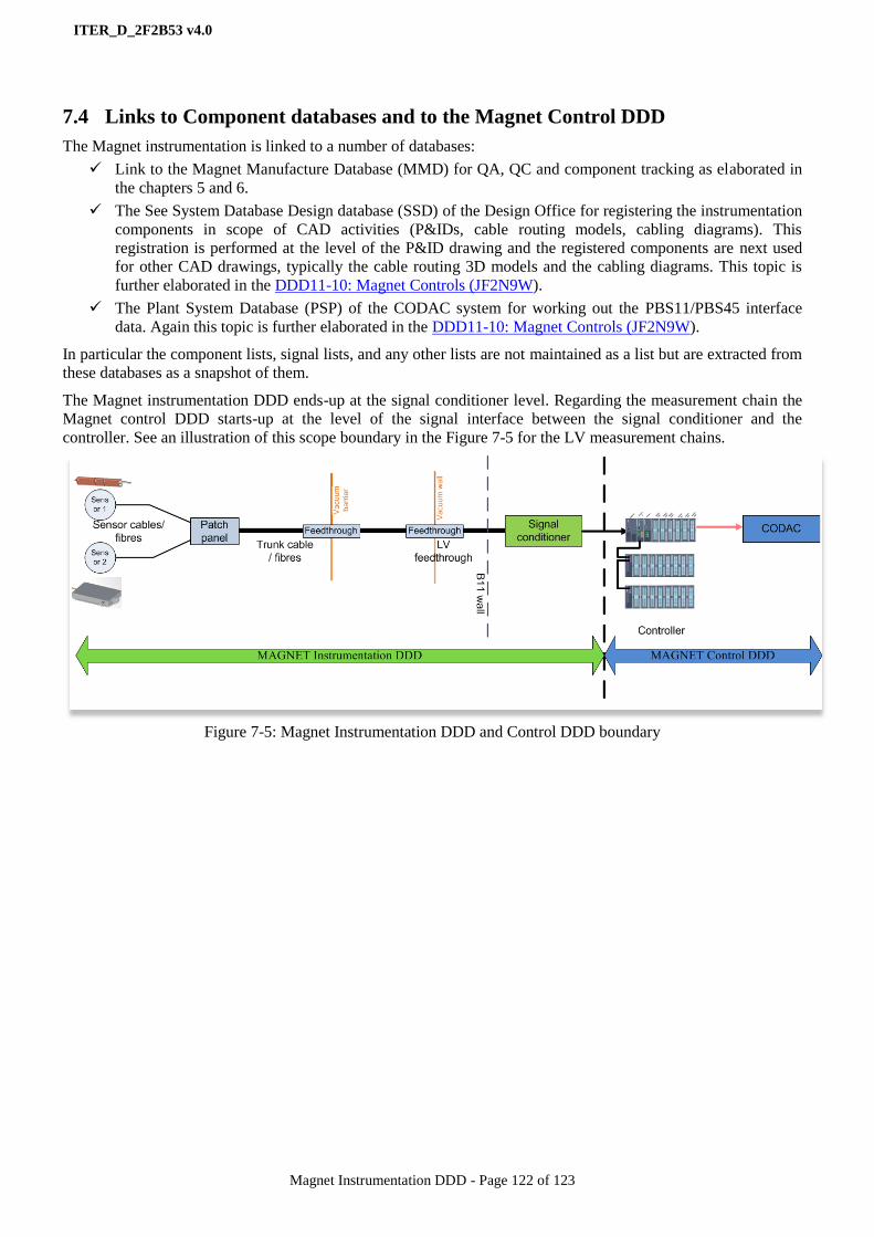
ITER_D_2F2B53 v4.0
Magnet Instrumentation DDD - Page 122 of 123
7.4 Links to Component databases and to the Magnet Control DDD
The Magnet instrumentation is linked to a number of databases:
Link to the Magnet Manufacture Database (MMD) for QA, QC and component tracking as elaborated in
the chapters 5 and 6.
The See System Database Design database (SSD) of the Design Office for registering the instrumentation
components in scope of CAD activities (P&IDs, cable routing models, cabling diagrams). This
registration is performed at the level of the P&ID drawing and the registered components are next used
for other CAD drawings, typically the cable routing 3D models and the cabling diagrams. This topic is
further elaborated in the DDD11-10: Magnet Controls (JF2N9W).
The Plant System Database (PSP) of the CODAC system for working out the PBS11/PBS45 interface
data. Again this topic is further elaborated in the DDD11-10: Magnet Controls (JF2N9W).
In particular the component lists, signal lists, and any other lists are not maintained as a list but are extracted from
these databases as a snapshot of them.
The Magnet instrumentation DDD ends-up at the signal conditioner level. Regarding the measurement chain the
Magnet control DDD starts-up at the level of the signal interface between the signal conditioner and the
controller. See an illustration of this scope boundary in the Figure 7-5 for the LV measurement chains.
Figure 7-5: Magnet Instrumentation DDD and Control DDD boundary

ITER_D_2F2B53 v4.0
Magnet Instrumentation DDD - Page 123 of 123
Appendix A
Applicable documents
[AD1] Project Requirements (27ZRW8 v4.6 or higher).
[AD2] ITER Electrical Design Handbook (EDH) - Part 1: Introduction (2F7HD2 v1.4 or higher).
[AD3] Plant Control Design Handbook (27LH2V v7.0 or higher)
[AD4] ITER Vacuum Handbook (2EZ9UM v2.3 or higher)
[AD5] ITER Policy on EEE in Tokamak Complex (6ZX6S3)
Reference documents
[RD1] DDD11-1: System Requirements Expansion and Design Choices (2NPLKM)
[RD2] DDD11-6: Feeders, CTBs and Current Leads (2NMSYG)
[RD3] DDD11-9: Instrumentation and controls (2F2B53)
[RD4] ITER Numbering System for Parts/Components (28QDBS)
[RD5] EDH Part 4: Electromagnetic compatibility (4B523E)
[RD6] ITER Quality Assurance Program (22K4QX)
[RD7] MQP Deviations and Non Conformances (for EXT) (22F53X)
[RD8] Safety requirement Room-book (KF63PB)
[RD9] ITER Procurement Quality Requirements (22MFG4).
[RD10] Deviations and Non Conformances (for IO) (2LZJHB)
[RD11] IO cabling rules (335VF9)
[RD12] EDH Guide C: Electrical Installations for EPS Client Systems (2F6BBN)
[RD13] IO out-cryostat cable catalogue (355QX2)
[RD14] IO In-cryostat cable catalogue (HXVPWS)
[RD15] Magnet Grounding scheme (QV49XG)