dear mifco customermifco.com/dip-outoperatingmanualforfm.pdfonly licensed electricians or qualified...
TRANSCRIPT
-1-
Dear MIFCO Customer:
We would like to thank and congratulate you on the purchase of the McEnglevan machine andaccessories, and to share with you our confidence in the quality and reliability of our equipment.
The enclosed Operating Manual and Warranty Registration Card are important to both of us fortwo reasons:
1. Your Registration Card, with proper serial number, will be documented in our files and yourwritten warranty will be forwarded to you upon the receipt of this card. Please complete andmail the return card now.
2. Proper instruction on the maintenance of your machine is very important. Please read yourinstruction manual completely for best results and maximum machine tool life.
Should you ever need service, it is available through the distributors, our factoryrepresentatives or directly from the factory. It is the obligation of our franchised distributor who sells youthis equipment to conduct field service where possible. Please contact your local distributor first andthey will assist you in resolving any problems you may encounter.
We take pride along with you in your purchase of this equipment. We will be happy to assist youin any way possible to receive optimum results in its operation and use.
Sincerely yours,
Matt WalterCEO
-2-
DO NOT REMOVE THIS PAGE
In accordance with the National Electric Code, A.G.A., Canadian Standard Association, O.S.H.A.,N.F.P.A., and the F.I.A. recommendations, this specification sheet must remain a part of this manual.Most of the components are U.L. and A.G.A. listed. The wiring and Ultra-Violet Combustion SafeguardSystems, designed to conform to Illinois O.S.P.I. Circular 156 as amended, are in compliance perapproval letter received from the Office of Public Instruction dated November 20,1974.
This manual contains the Electrical Wiring schematic applicable to this particular equipment. Ifthere are any questions, contact your distributor or the factory. Only licensed electricians or qualifiedfactory representatives should trouble shoot the electrical system of this equipment.
The electrical portion of this equipment is built in compliance with the National Electric Code ineffect as of this date.
Purchased from ________________________________________ Date _____________________
City ______________________ State __________ Zip Code _____________________________
Model Number _____________________ Serial Number __________________________________
Electrical Service Specifications
____________________ Volts _____________________ Phase ___________________ Hertz
Note: Schematic drawings showing different voltages, phase and hertz data are included in the manual.
The Drawing Number for this furnace is: ______________
Note:Maximum incoming gas pressure: 7 psi.
HIGHER PRESSURE WILL DAMAGE REGULATOR AND MODULAR VALVE SYSTEM.
-3-
MIFCO PROPORTIONING BURNER FURNACES
When your furnace was ordered, your company was contacted to determine the gas pressurethat would be available at your furnace installation. The gas regulator that is part of this burner systemwas sized accordingly. The unit was test fired as close to this pressure as was possible. Only minoradjustments should be necessary, if at all.
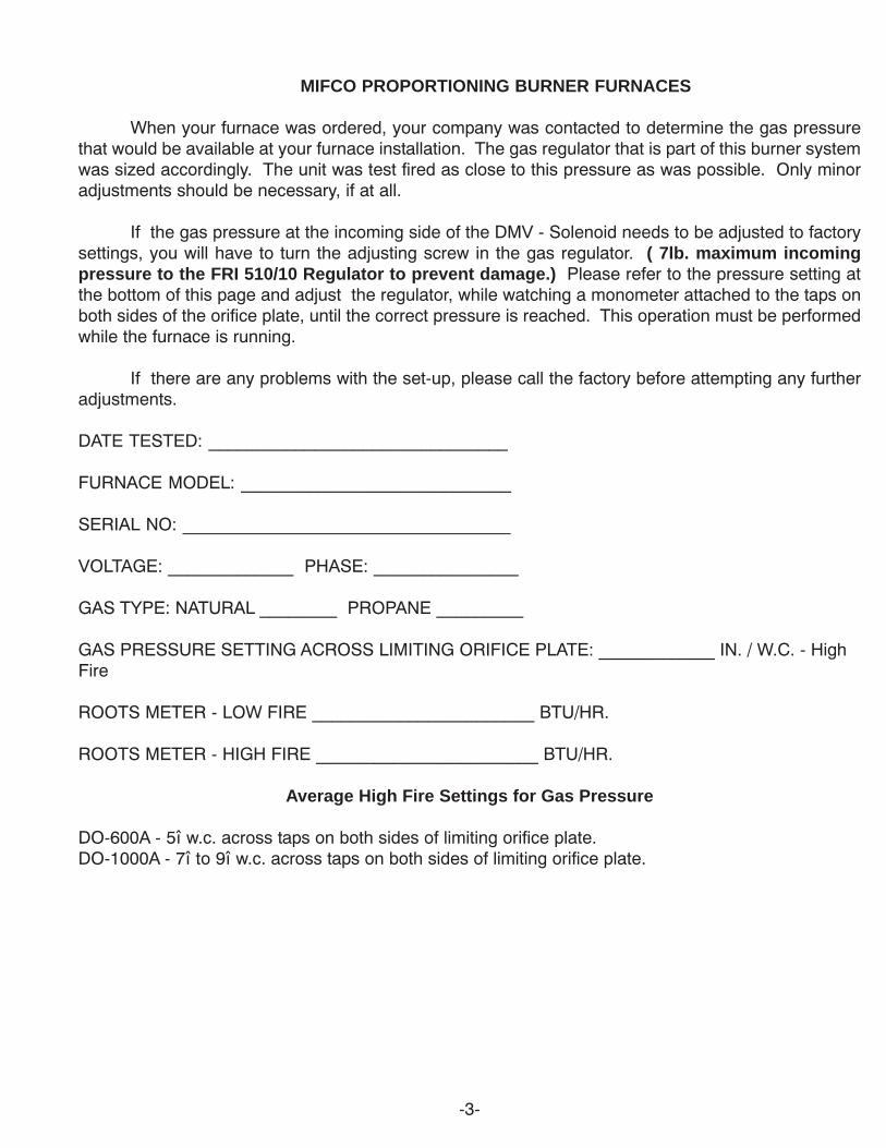
If the gas pressure at the incoming side of the DMV - Solenoid needs to be adjusted to factorysettings, you will have to turn the adjusting screw in the gas regulator. ( 7lb. maximum incomingpressure to the FRI 510/10 Regulator to prevent damage.) Please refer to the pressure setting atthe bottom of this page and adjust the regulator, while watching a monometer attached to the taps onboth sides of the orifice plate, until the correct pressure is reached. This operation must be performedwhile the furnace is running.
If there are any problems with the set-up, please call the factory before attempting any furtheradjustments.
DATE TESTED: _______________________________
FURNACE MODEL: ____________________________
SERIAL NO: __________________________________
VOLTAGE: _____________ PHASE: _______________
GAS TYPE: NATURAL ________ PROPANE _________
GAS PRESSURE SETTING ACROSS LIMITING ORIFICE PLATE: ____________ IN. / W.C. - HighFire
ROOTS METER - LOW FIRE _______________________ BTU/HR.
ROOTS METER - HIGH FIRE _______________________ BTU/HR.
Average High Fire Settings for Gas Pressure
DO-600A - 5î w.c. across taps on both sides of limiting orifice plate.DO-1000A - 7î to 9î w.c. across taps on both sides of limiting orifice plate.
-4-
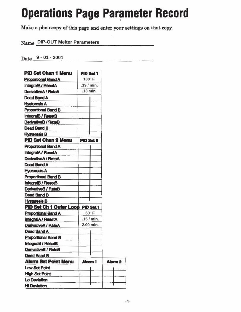
138o F
.19 / min..13 min.
60o F
.15 / min.2.00 min.
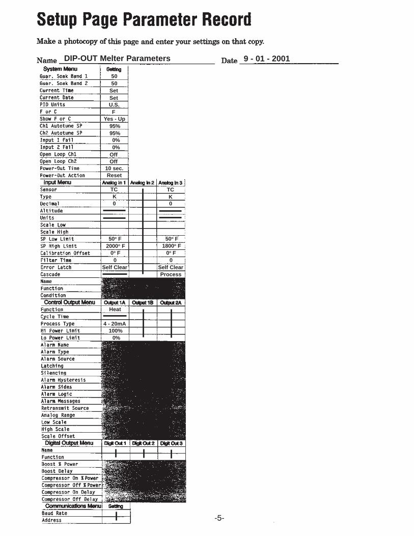
DIP-OUT Melter Parameters
9 - 01 - 2001
-5-
U.S.F
Yes - Up
TCK0
2000o F0o F0
Self Clear
DIP-OUT Melter Parameters 9 - 01 - 2001
5050
SetSet
95%95%0%0%
OffOff
10 sec.Reset
TCK0
50o F 50o F1800o F
0o F0
Self ClearProcess
Heat
4 - 20mA100%
0%
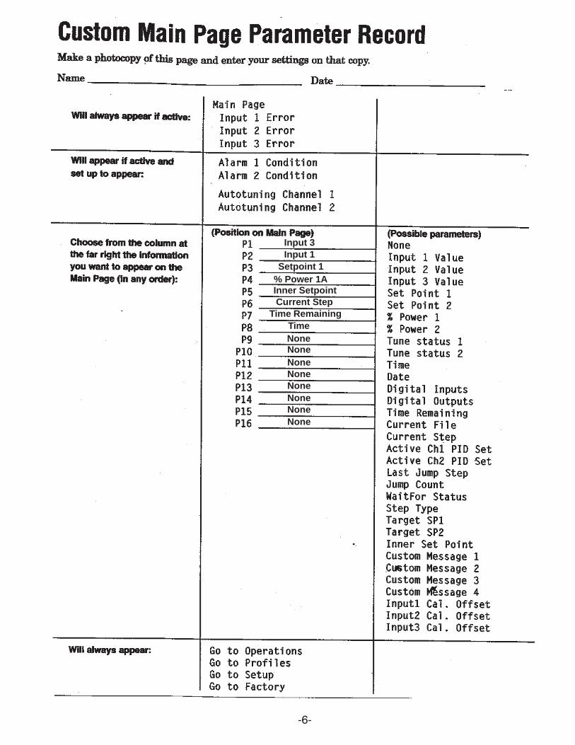
-6-
Input 3Input 1
Setpoint 1% Power 1AInner Setpoint
NoneNoneNoneNoneNoneNone
NoneNone
Current StepTime Remaining
Time

-7-
2050o F0
Chamber Temp.SAFE
TCH
50o F2050o F0
0
HI3
PR 1
USER
SAFE
OUCH
FNON
-8-
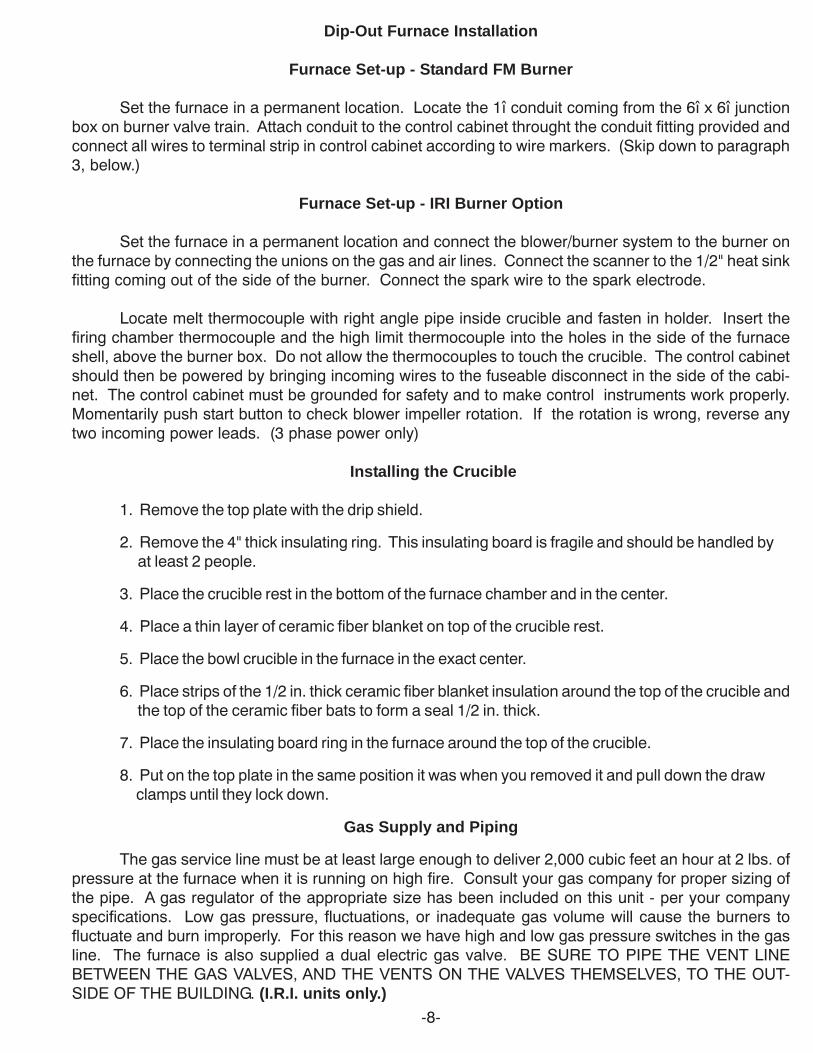
Dip-Out Furnace Installation
Furnace Set-up - Standard FM Burner
Set the furnace in a permanent location. Locate the 1î conduit coming from the 6î x 6î junctionbox on burner valve train. Attach conduit to the control cabinet throught the conduit fitting provided andconnect all wires to terminal strip in control cabinet according to wire markers. (Skip down to paragraph3, below.)
Furnace Set-up - IRI Burner Option
Set the furnace in a permanent location and connect the blower/burner system to the burner onthe furnace by connecting the unions on the gas and air lines. Connect the scanner to the 1/2" heat sinkfitting coming out of the side of the burner. Connect the spark wire to the spark electrode.
Locate melt thermocouple with right angle pipe inside crucible and fasten in holder. Insert thefiring chamber thermocouple and the high limit thermocouple into the holes in the side of the furnaceshell, above the burner box. Do not allow the thermocouples to touch the crucible. The control cabinetshould then be powered by bringing incoming wires to the fuseable disconnect in the side of the cabi-net. The control cabinet must be grounded for safety and to make control instruments work properly.Momentarily push start button to check blower impeller rotation. If the rotation is wrong, reverse anytwo incoming power leads. (3 phase power only)
Installing the Crucible
1. Remove the top plate with the drip shield.
2. Remove the 4" thick insulating ring. This insulating board is fragile and should be handled byat least 2 people.
3. Place the crucible rest in the bottom of the furnace chamber and in the center.
4. Place a thin layer of ceramic fiber blanket on top of the crucible rest.
5. Place the bowl crucible in the furnace in the exact center.
6. Place strips of the 1/2 in. thick ceramic fiber blanket insulation around the top of the crucible and the top of the ceramic fiber bats to form a seal 1/2 in. thick.
7. Place the insulating board ring in the furnace around the top of the crucible.
8. Put on the top plate in the same position it was when you removed it and pull down the draw clamps until they lock down.
Gas Supply and Piping
The gas service line must be at least large enough to deliver 2,000 cubic feet an hour at 2 lbs. ofpressure at the furnace when it is running on high fire. Consult your gas company for proper sizing ofthe pipe. A gas regulator of the appropriate size has been included on this unit - per your companyspecifications. Low gas pressure, fluctuations, or inadequate gas volume will cause the burners tofluctuate and burn improperly. For this reason we have high and low gas pressure switches in the gasline. The furnace is also supplied a dual electric gas valve. BE SURE TO PIPE THE VENT LINEBETWEEN THE GAS VALVES, AND THE VENTS ON THE VALVES THEMSELVES, TO THE OUT-SIDE OF THE BUILDING. (I.R.I. units only.)

-9-
Furnace Preparation Prior to Start-up
DO NOT OBSTRUCT THE EXHAUST PORT IN ANY MANNER WHILE IN OPERATION.
If the crucible breaks while in the furnace, the molten metal will flow out the drain on the floor ofthe furnace. Be sure the drain hole remains unobstructed by checking it regularly.
A layer of high temperature refractory insulation is cast between the pre-burned high aluminalining and the steel furnace shell. This increases melting efficiency and reduces heat loss through thefurnace walls to a minimum. Because the insulation is a castable material, a certain amount of moistureis absorbed by the furnace lining. It is recommended that the initial firing periods should not exceedfifteen minutes, to allow the lining to expel the moisture slowly. The moisture may appear as steam ordrops of water. Two or three short firing periods will be sufficient to remove the excess moisture. To drythe insulation, fire at about 1/3 of the firing rate until the steaming stops and moisture stops coming outof the furnace. After the furnace has been fired at low temperature, up to 1000o F for a day's time usingseveral firing periods, it will be ready to fire at full fire.
Instructions in the Use and Care of Crucibles should be followed as closely as possible. Thispractice is routine in the foundry trade, and will increase crucible life and prevent failure due to crackingand spalling.
Standard FM Burner System - Sequence of Operation
1. Depress the start button. Power is applied to the Honeywell Control Module.
2. The system goes through a self diagnostic check. During this segment, the Control Module tests allcircuits for continuity, makes sure that all valves are in their proper positions and analyzes theTemperature Control Instrument as well. At the same time, the Temperature Control Instrument isperforming its own internal diagnostics.
3. Once everything is checked out and is in proper position, the Control Module powers the blower andthesystem then goes through a 60 second pre-purge to insure that there are no combustible gasespresent in the firing chamber. After this pre-purge, the system undergoes a 15 second purge hold.After the purge hold, there is a 10 second pilot ignition period during which the low fire is established.Once low fire is established and proven, the unit goes to a run mode. At this point the safety systemis done with its tests and control is taken over by the Temperature Control Instrument.
6. Enter a set point in the Temperature Control Instrument and the furnace will travel to that setpointand remain there until a change is made. For further information about the Temperature ControlInstrument, see the page entitled: Programming the Control Instrument.
I.R.I. Burner System - Sequence of Operation
1. Depress the start button. Power is applied to the Honeywell Control Module.
2. The system goes through a self diagnostic check. During this segment, the Control Module tests allcircuits for continuity, makes sure that all valves are in their proper positions and analyzes theTemperature Control Instrument as well. At the same time, the Temperature Control Instrument isperforming its own internal diagnostics.

-10-
I.R.I. Burner System - Sequence of Operation - (cont.)
3. Once everything is checked out and is in proper position, the Control Module powers the blower andopens the air modulating motor to the High Air position. The system then goes through a 60 secondHigh Air Purge to insure that there are no combustible gases present in the firing chamber. After thispurge, the air modulating motor is driven closed and the Low Fire Interlock Switch is made.
4. At this point the spark ignition and bypass pilot come on. After a 10 second trial ignition period, thespark ignition turns off and the bypass pilot stays on. When the Control Module has a good flamesignal, it turns on the Main Gas.
5. When the Main Gas comes on, the Control Module checks again to be sure that there is a goodflame signal, then the bypass pilot takes over. At this point the safety system is done with its testsand control is taken over by the Temperature Control Instrument.
6. Enter a set point in the Temperature Control Instrument and the furnace will travel to that setpointand remain there until a change is made. For further information about the Temperature ControlInstrument, see the page entitled: Programming the UDC-3300
Re-ignition After Flame Failure
1. When there is a flame failure, the Flame Failure light on the control panel will be lit. Reset the UVSafety System by depressing the reset button on the Honeywell Flame Safety control box. TheSafety System will not reset until the motor is at a complete stop.
2. If the Honeywell control will not reset after flame failure refer to the Diagnostic Keypad. The HoneywellFlame Safety system is equipped with a diagnostic read-out. If the furnace cannot be restartedplease refer to the Keyboard Display Module section of this manual for a listing of the error codes.This will help determine which component has failed.

-11-
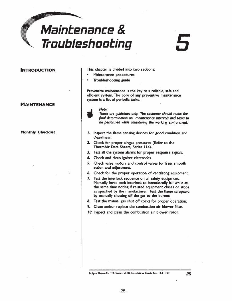
Maintenance
All McEnglevan furnaces are constructed with hard, pre-burned sectional refractory shapes.Each brick is made by air ramming the granular refractory particles into a steel mold, forming thedesired shape. The shape is removed from the mold, dried to remove all moisture, then fired. Defectivebricks fail during the final burning and are discarded. This assures controlled quality refractory for allMcEnglevan furnacesbefore assembly into a furnace lining.
We can control quality through the point of manufacture of the furnace, but preventativemaintenance is necessary for maximum productive life of the furnace lining. The exposed surfacesof the refractory lining should be resealed when scuffing and wear takes place.
Minro Wash Refractory Sealer for Furnace Lining
Minro Wash is a dry, air setting bonding mortar that gives an exceptionally strong bond at alltemperatures. Minro Wash sealer, unlike most dry mortars, is ready to use immediately after mixingwith water. When mixing is completed, its fine workability has already been developed and the bondingagent is completely dissolved, ready to put on the brick surface. The sealer forms a mechanical bondwith the refractory wall and in order for it to form a ceramic bond the furnace should be taken to 2000o
F. The mechanical bond in the sealer will burn away by 1500∞ and the sealer will fall off unless the2000∞ F+ temperature is reached. The maximum temperature rating of the sealer is 3000∞F.
Refractory Plastic Patching Material
If the refractory lining has been chipped or broken, and the damaged areas are too large to befilled with refractory sealer, they should be filled with patching material. The plastic patching material isa similar material as the sealer except that it is pre-mixed and has a putty consistency.
Application of Sealer and Patching Material
Remove all loose scale and foreign material from the surface to be sealed. Wire brush to re-move flux and old loose sealer. Excessive flux and spilled metal are detrimental to refractory andshould be removed prior to resealing. Prepare the surface by priming with a saturated solution ofsodium silicate (water glass). This material is available from drug supply houses. Brush or sponge thesolution liberally on the refractory.
The refractory patching material should be used at this point to fill larger holes. Saturate dam-aged areas with primer or water. Work a thin layer of plastic into the damaged section. This forms astrong bond between the refractory and patching plastic. Place a layer of patching plastic with a maxi-mum thickness of 1/8î into the area being filled.The thin patch should be allowed to dry for one hour, then the area heated to a red temperature by usingthe furnace. When the furnace has cooled, add another thin layer, not exceeding 1/8î thick until thepatch conforms to the original contour of the furnace lining. If the procedure of applying and 'burning in"the successive thin layers is not followed and a heavy patch is used to fill the damaged area, themoisture retained in the center of the heavy patch will generate sufficient steam to cause it to ruptureand peel.
After the primer has been applied, and any severely damaged sections have been repaired withplastic patching, prepare the sealer as follows:
-12-
Application of Sealer and Patching Material (cont.)
Step 1 Use one pint of warm water in a metal container.
Step 2 Sift the refractory into the water while stirring constantly.
Step 3 Remove the lid from the furnace so both the bottom and top surfaces can be sealed. With the use of a sponge, saturate exposed refractory with water and immediately brush the prepared sealer into the surface of the refractory lining and lid. Unless the refractory is presaturated with water, it will draw the moisture from the sealer, preventing a tight bonding action and the seal coating will peel. (Light coatings applied often, are more satisfactory than one heavy application).
Step 4 Allow the furnace to dry for a period of at least two hours.
Step 5 Light furnace and fire slowly for about five minutes, then shut furnace down. (This provides heat to expel moisture from the patching plastic).
Step 6 Allow the furnace to dry an additional one hour, then light furnace and increase heat slowly to red heat. The furnace chamber should be inspected and cleaned of any accumulation of slag or spilled metal prior to start up. Proper cleaning and the use of sealer should triple the life of the refractory in your furnace.
The Use and Care of Foundry Crucibles
Composition - Types of Material
Crucibles are manufactured in two basic compositions; the clay graphite ceramic bonded andthe silicon carbide carbon bonded types. Both types utilize the refractory materials, graphite and silicon,as conductors of heat and for structural strength. Graphite is predominant in the composition of the claygraphite crucible while silicon carbide predominates in the silicon carbide crucible. Due to its higherheat conductivity and greater strength, the silicon carbide crucible is more popular in industry. The lessexpensive clay graphite crucible is generally used in the school shop. Crucible failure in school shopsis generally due to mishandling by inexperienced students, so the benefits of the more expensive siliconcarbide crucible would not be realized.
Either type crucible can be used for melting aluminum, brass, or grey iron. However, differentmetals should not be melted in the same crucible. This practice will cause contamination of each meltand it will be very difficult to get good castings. Different crucibles should be used for each type of metalmelted. If grey iron is to be melted in appreciable quantity, a special clay lined silicon carbide crucibleis recommended. Do not use just ìany sizesî crucible in your furnace. Use the size for which thefurnace was designed. To prevent oxidation of the crucible wall, always melt with a full charge in thecrucible. Half full crucible melts will shorten crucible life considerably.
-13-
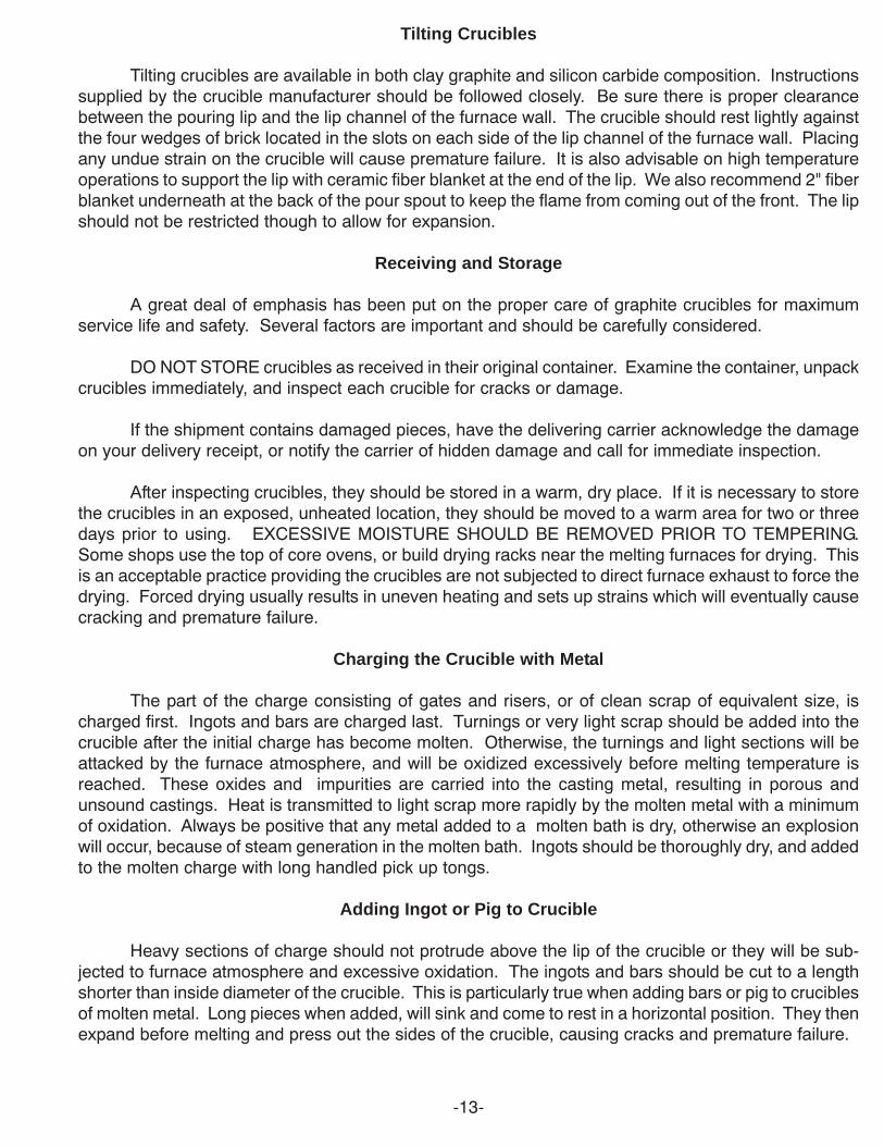
Tilting Crucibles
Tilting crucibles are available in both clay graphite and silicon carbide composition. Instructionssupplied by the crucible manufacturer should be followed closely. Be sure there is proper clearancebetween the pouring lip and the lip channel of the furnace wall. The crucible should rest lightly againstthe four wedges of brick located in the slots on each side of the lip channel of the furnace wall. Placingany undue strain on the crucible will cause premature failure. It is also advisable on high temperatureoperations to support the lip with ceramic fiber blanket at the end of the lip. We also recommend 2" fiberblanket underneath at the back of the pour spout to keep the flame from coming out of the front. The lipshould not be restricted though to allow for expansion.
Receiving and Storage
A great deal of emphasis has been put on the proper care of graphite crucibles for maximumservice life and safety. Several factors are important and should be carefully considered.
DO NOT STORE crucibles as received in their original container. Examine the container, unpackcrucibles immediately, and inspect each crucible for cracks or damage.
If the shipment contains damaged pieces, have the delivering carrier acknowledge the damageon your delivery receipt, or notify the carrier of hidden damage and call for immediate inspection.
After inspecting crucibles, they should be stored in a warm, dry place. If it is necessary to storethe crucibles in an exposed, unheated location, they should be moved to a warm area for two or threedays prior to using. EXCESSIVE MOISTURE SHOULD BE REMOVED PRIOR TO TEMPERING.Some shops use the top of core ovens, or build drying racks near the melting furnaces for drying. Thisis an acceptable practice providing the crucibles are not subjected to direct furnace exhaust to force thedrying. Forced drying usually results in uneven heating and sets up strains which will eventually causecracking and premature failure.
Charging the Crucible with Metal
The part of the charge consisting of gates and risers, or of clean scrap of equivalent size, ischarged first. Ingots and bars are charged last. Turnings or very light scrap should be added into thecrucible after the initial charge has become molten. Otherwise, the turnings and light sections will beattacked by the furnace atmosphere, and will be oxidized excessively before melting temperature isreached. These oxides and impurities are carried into the casting metal, resulting in porous andunsound castings. Heat is transmitted to light scrap more rapidly by the molten metal with a minimumof oxidation. Always be positive that any metal added to a molten bath is dry, otherwise an explosionwill occur, because of steam generation in the molten bath. Ingots should be thoroughly dry, and addedto the molten charge with long handled pick up tongs.
Adding Ingot or Pig to Crucible
Heavy sections of charge should not protrude above the lip of the crucible or they will be sub-jected to furnace atmosphere and excessive oxidation. The ingots and bars should be cut to a lengthshorter than inside diameter of the crucible. This is particularly true when adding bars or pig to cruciblesof molten metal. Long pieces when added, will sink and come to rest in a horizontal position. They thenexpand before melting and press out the sides of the crucible, causing cracks and premature failure.

-14-
Preheating Charge Metal
It is very poor practice to preheat scrap or bars by placing them across the exhaust port in the lidof the furnace. Such practice causes excessive oxidation of the metal and will result in poor castings.For the same reason, long bars should not protrude through the exhaust port into the crucible. Inextreme cases, some of the bars will reach melting temperature, allowing the molten metal to run downinside the furnace lid and walls. This molten metal is oxidized very rapidly and attacks the refractorylining, causing premature replacement of the lid and lining. Ingots can be placed around the lid, wellaway from the exhaust port.

-15-
Programming the Control Instrument
First of all, the Watlow Control Instrument is pre-programmed here at the factory and has tuningparameters entered into it that have been arrived at by extensive testing. Everyoneís needs are differentand the control parameters chosen were decided on for a mixture of speed, to get the metal up totemperature as fast as possible and to recover additional metal to pouring temperature quickly, and tominimize overshoot of the setpoint. You may decide to tune the instrument to suit your needs moreclosely. This is a relatively easy process, but it is strongly suggested that you read the accompanyingbook on your particular Watlow Controller FIRST.
To enter a setpoint into the controller, look at the lower display of the instrument. You will noticethat the Setpoint 1 is the third parameter displayed. Use the down arrow to get to it, then the right arrowto enter the setpoint. Use the up or down arrows to determine the setpoint and right arrow again, afterthe setpoint is entered. The burner should begin to go to high fire. This is all that is required.
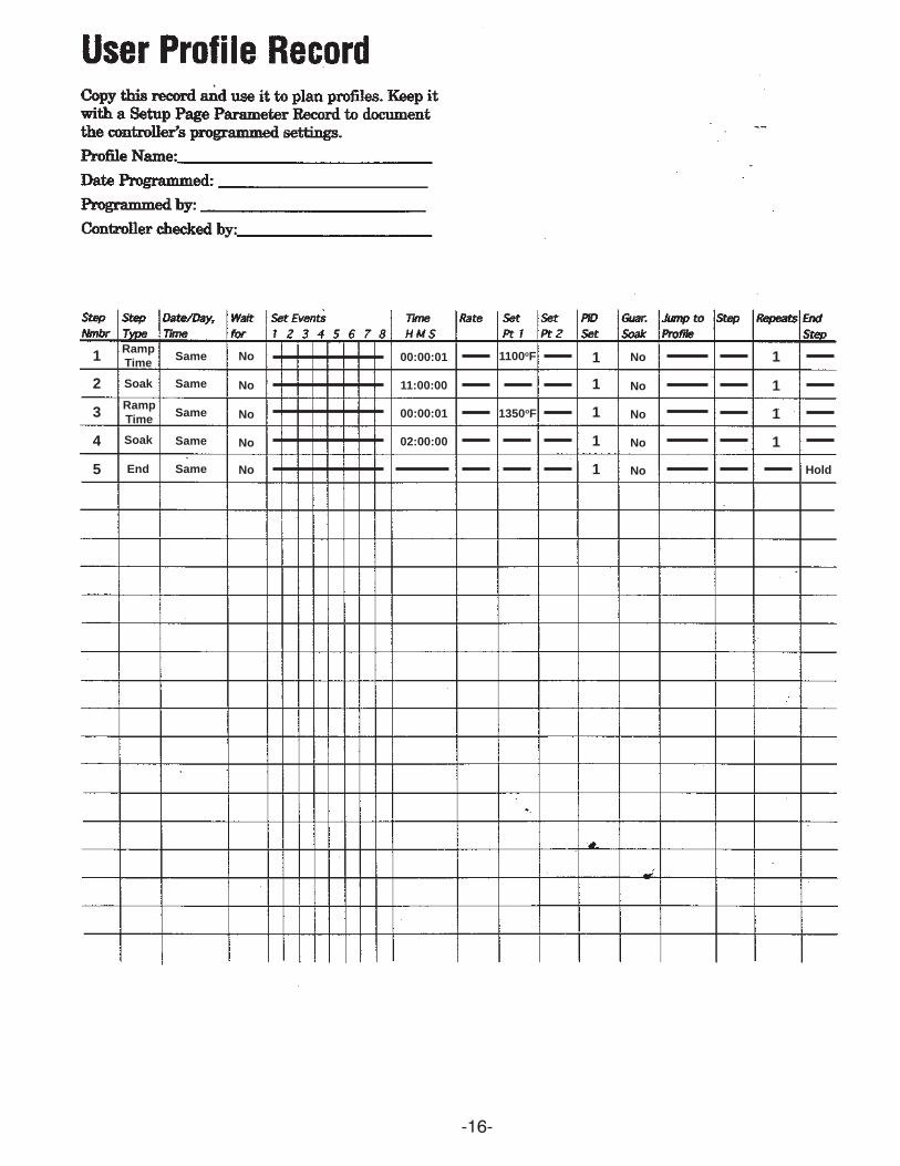
Entering a Ramp / Soak Profile
The instrument is shipped from our factory with a sample profile that is named OVERNITE 1. Itcan be viewed by going down the Main Page list in the lower display to the line that says Go to Profiles.Use the right arrow to go into the group. The display will read Create Profile, Edit Profile, Delete Profile.Choose Edit Profile and use the right arrow to step through the existing profile. OVERNITE 1 is a simple5 step profile for idling the furnace down at 5:00 pm to a setpoint of 1100oF. Step 1 has a ramp time of 1second, the lowest setting, to immediately change the setpoint. Step 2 is a 11 hour soak period to holdthe metal at the setpoint until 4:00 am. Step 3 is a 1 second ramp back up to a setpoint of 1350oF. Step4 is a soak period of 2 hours at the setpoint and will get the metal back up to temperature for pouring by6:00 am. Step 5 is the end segment. This tells the controller what to do at the end of the profile. In thiscase, we have programmed it to hold at the final setpoint. We do not employ the feature called guaranteedsoak, which delays timing of steps until the process temperature is within a specified range of thesetpoint, because of the nature of the process in a melting furnace.
There are other questions that have to be answered for each step when a profile is being createdthat tell it to perform certain functions, or to observe certain parameters. Refer to the sample profilepage on the next page of this manual to see the standard settings for these steps in this furnace. It isalso strongly suggested that you refer to the chapter on page 4.1, entitled Profile Programming, of theWatlow manual supplied with this operating manual for further details pertaining to creating profiles.
To run the profile, press the profile button in the lower left corner of the instrument. It will askwhich profile you wish to run. Select the profile, right arrow out of the group, and the profile will start.You can confirm this by referring to the lower display. Line 6 reads out the current step, line 7 tells thetime remaining for that step, and line 8 tells the actual time in 24 clock readout. To stop a profile, pressthe profile button again and tell the instrument to terminate the profile. Right arrow out of the group andthe profile terminates. The Setpoint 1 reading will say OFF. Arrow down to the Setpoint 1 line and rightarrow into it, enter a setpoint again and right arrow out of the group and a new setpoint will be entered.
-16-
1
2
3
4
5
RampTime
RampTime
Soak
Soak
End
Same
Same
Same
Same
Same
No
No
No
No
No
00:00:01
11:00:00
00:00:01
02:00:00
1100oF
1350oF
1
1
1
1
1
No
No
No
No
No
1
1
1
1
Hold
-17-
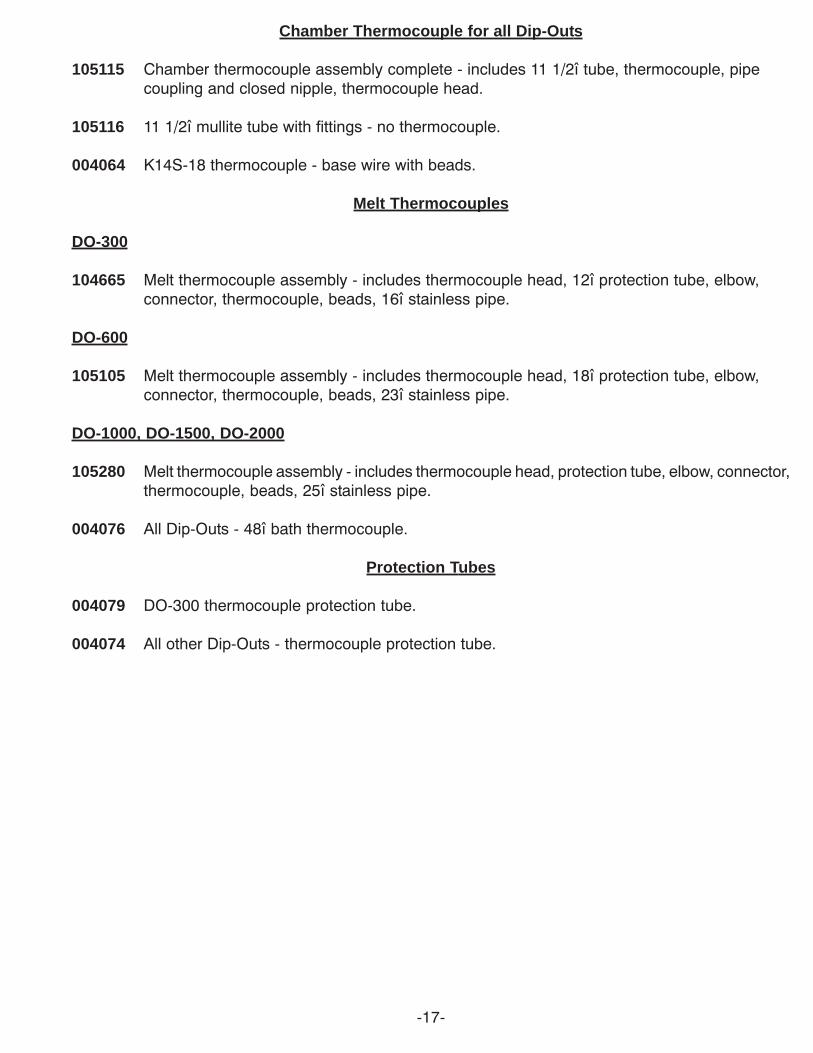
Chamber Thermocouple for all Dip-Outs
105115 Chamber thermocouple assembly complete - includes 11 1/2î tube, thermocouple, pipecoupling and closed nipple, thermocouple head.
105116 11 1/2î mullite tube with fittings - no thermocouple.
004064 K14S-18 thermocouple - base wire with beads.
Melt Thermocouples
DO-300
104665 Melt thermocouple assembly - includes thermocouple head, 12î protection tube, elbow,connector, thermocouple, beads, 16î stainless pipe.
DO-600
105105 Melt thermocouple assembly - includes thermocouple head, 18î protection tube, elbow,connector, thermocouple, beads, 23î stainless pipe.
DO-1000, DO-1500, DO-2000
105280 Melt thermocouple assembly - includes thermocouple head, protection tube, elbow, connector,thermocouple, beads, 25î stainless pipe.
004076 All Dip-Outs - 48î bath thermocouple.
Protection Tubes
004079 DO-300 thermocouple protection tube.
004074 All other Dip-Outs - thermocouple protection tube.
-18-
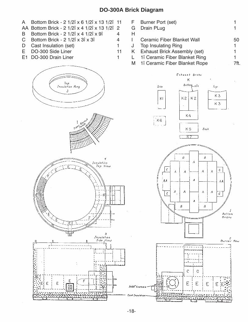
DO-300A Brick Diagram
A Bottom Brick - 2 1/2î x 6 1/2î x 13 1/2î 11 F Burner Port (set) 1AA Bottom Brick - 2 1/2î x 4 1/2î x 13 1/2î 2 G Drain PLug 1B Bottom Brick - 2 1/2î x 4 1/2î x 9î 4 HC Bottom Brick - 2 1/2î x 3î x 3î 4 I Ceramic Fiber Blanket Wall 50D Cast Insulation (set) 1 J Top Insulating Ring 1E DO-300 Side Liner 11 K Exhaust Brick Assembly (set) 1E1 DO-300 Drain Liner 1 L 1î Ceramic Fiber Blanket Ring 1
M 1î Ceramic Fiber Blanket Rope 7ft.
-19-
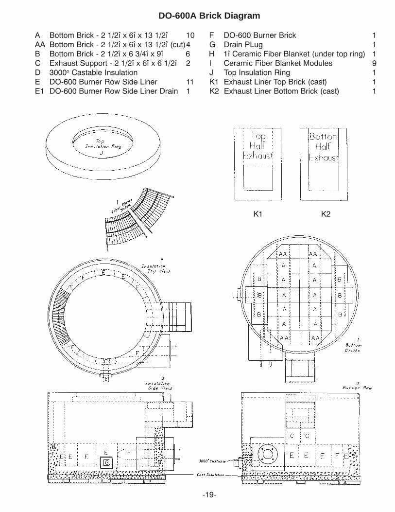
DO-600A Brick Diagram
A Bottom Brick - 2 1/2î x 6î x 13 1/2î 10 F DO-600 Burner Brick 1AA Bottom Brick - 2 1/2î x 6î x 13 1/2î (cut)4 G Drain PLug 1B Bottom Brick - 2 1/2î x 6 3/4î x 9î 6 H 1î Ceramic Fiber Blanket (under top ring) 1C Exhaust Support - 2 1/2î x 6î x 6 1/2î 2 I Ceramic Fiber Blanket Modules 9D 3000o Castable Insulation J Top Insulation Ring 1E DO-600 Burner Row Side Liner 11 K1 Exhaust Liner Top Brick (cast) 1E1 DO-600 Burner Row Side Liner Drain 1 K2 Exhaust Liner Bottom Brick (cast) 1
K1 K2
-20-
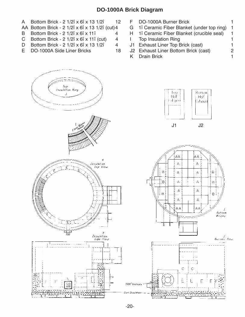
DO-1000A Brick Diagram
A Bottom Brick - 2 1/2î x 6î x 13 1/2î 12 F DO-1000A Burner Brick 1AA Bottom Brick - 2 1/2î x 6î x 13 1/2î (cut)4 G 1î Ceramic Fiber Blanket (under top ring) 1B Bottom Brick - 2 1/2î x 6î x 11î 4 H 1î Ceramic Fiber Blanket (crucible seal) 1C Bottom Brick - 2 1/2î x 6î x 11î (cut) 4 I Top Insulation Ring 1D Bottom Brick - 2 1/2î x 6î x 13 1/2î 4 J1 Exhaust Liner Top Brick (cast) 1E DO-1000A Side Liner Bricks 18 J2 Exhaust Liner Bottom Brick (cast) 2
K Drain Brick 1
J1 J2
-21-
L1 105310 - Lid Assembly - includes105348 Fulcrum
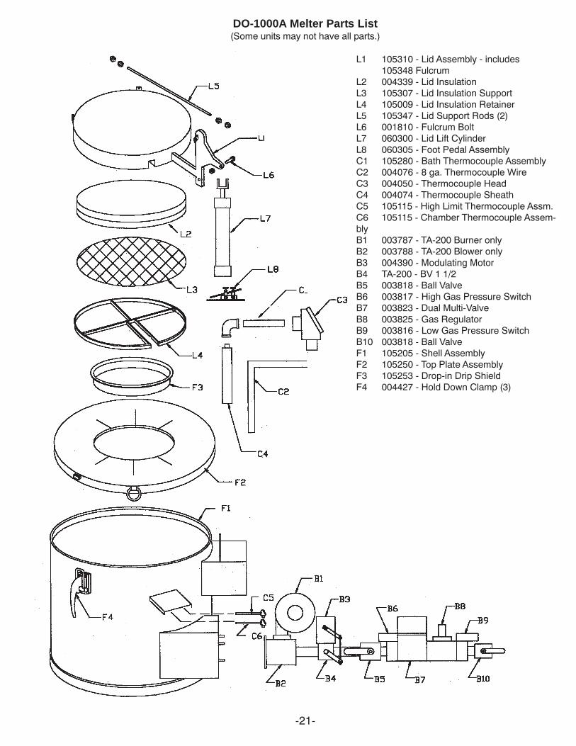
L2 004339 - Lid InsulationL3 105307 - Lid Insulation SupportL4 105009 - Lid Insulation RetainerL5 105347 - Lid Support Rods (2)L6 001810 - Fulcrum BoltL7 060300 - Lid Lift CylinderL8 060305 - Foot Pedal AssemblyC1 105280 - Bath Thermocouple AssemblyC2 004076 - 8 ga. Thermocouple WireC3 004050 - Thermocouple HeadC4 004074 - Thermocouple SheathC5 105115 - High Limit Thermocouple Assm.C6 105115 - Chamber Thermocouple Assem-blyB1 003787 - TA-200 Burner onlyB2 003788 - TA-200 Blower onlyB3 004390 - Modulating MotorB4 TA-200 - BV 1 1/2B5 003818 - Ball ValveB6 003817 - High Gas Pressure SwitchB7 003823 - Dual Multi-ValveB8 003825 - Gas RegulatorB9 003816 - Low Gas Pressure SwitchB10 003818 - Ball ValveF1 105205 - Shell AssemblyF2 105250 - Top Plate AssemblyF3 105253 - Drop-in Drip ShieldF4 004427 - Hold Down Clamp (3)
DO-1000A Melter Parts List(Some units may not have all parts.)
-22-
L1 105121 - Lid Assembly - includes105348 Fulcrum
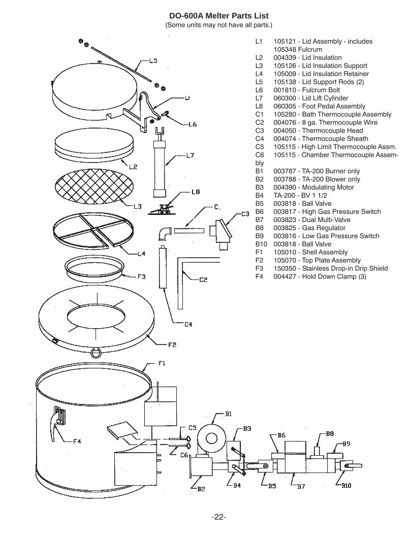
L2 004339 - Lid InsulationL3 105126 - Lid Insulation SupportL4 105009 - Lid Insulation RetainerL5 105138 - Lid Support Rods (2)L6 001810 - Fulcrum BoltL7 060300 - Lid Lift CylinderL8 060305 - Foot Pedal AssemblyC1 105280 - Bath Thermocouple AssemblyC2 004076 - 8 ga. Thermocouple WireC3 004050 - Thermocouple HeadC4 004074 - Thermocouple SheathC5 105115 - High Limit Thermocouple Assm.C6 105115 - Chamber Thermocouple Assem-blyB1 003787 - TA-200 Burner onlyB2 003788 - TA-200 Blower onlyB3 004390 - Modulating MotorB4 TA-200 - BV 1 1/2B5 003818 - Ball ValveB6 003817 - High Gas Pressure SwitchB7 003823 - Dual Multi-ValveB8 003825 - Gas RegulatorB9 003816 - Low Gas Pressure SwitchB10 003818 - Ball ValveF1 105010 - Shell AssemblyF2 105070 - Top Plate AssemblyF3 150350 - Stainless Drop-in Drip ShieldF4 004427 - Hold Down Clamp (3)
DO-600A Melter Parts List(Some units may not have all parts.)
-23-
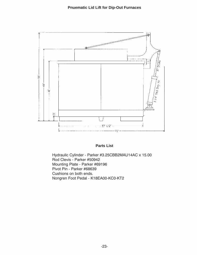
Pnuematic Lid Lift for Dip-Out Furnaces
Parts List
Hydraulic Cylinder - Parker #3.25CBB2MAU14AC x 15.00Rod Clevis - Parker #50942Mounting Plate - Parker #69196Pivot Pin - Parker #68639Cushions on both ends.Nongren Foot Pedal - K18EA00-KC0-KT2
-24-
-25-
-26-

-27-
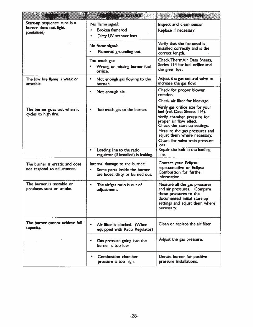
-28-
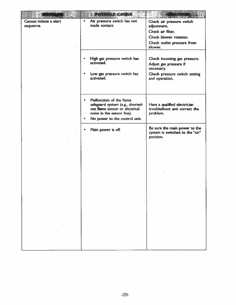
-29-