debugging embedded mixed-signal designs using · pdf filedebugging embedded mixed-signal...
TRANSCRIPT
Debugging Embedded Mixed-Signal DesignsUsing Mixed Signal Oscilloscopes
Application Note 1562
Introduction
Today’s embedded designs basedon microcontrollers (MCUs) anddigital signal processors (DSPs)often include a combination of analog and digital signalcontent. Design engineers have traditionally used bothoscilloscopes and logic analyzersto test and debug thesemixed-signal embedded designs,but a new class of measurementtools known as mixed signaloscilloscopes (MSOs) may offer abetter way for you to debug yourMCU- and DSP-based designs.
Although MSOs have been on the market for nearly ten years,most engineers have never usedone, and many engineers havemisconceptions about theirbenefits and use model. Withmore oscilloscope vendorsintroducing hybrid time-domaininstruments that mergetime-correlated analog and digitalmeasurement capabilities, it isimportant that you understandthe differences between theseinstruments and that you areaware of what they can andcannot do.
Table of Contents
Introduction . . . . . . . . . . . . . . . . . . . . . . . 1
What is a mixed signal oscilloscope (MSO)? . . . . . . . . . . . . . . . 2
Typical MSO measurement applications and required performance . . . . . . . . . . . . . . . . . . . . . . . 4
Triggering on mixed signals . . . . . . . . . 7
Turning on and debugging a real mixed-signal embedded design . . . . . 11
Limitation of MSOs . . . . . . . . . . . . . . . . 15
Summary . . . . . . . . . . . . . . . . . . . . . . . . . 16
Glossary . . . . . . . . . . . . . . . . . . . . . . . . . 17
Support, Services, and Assistance . . 19
This paper begins by definingmixed signal oscilloscopes,including an overview of theprimary applications where MSOs should be used. This paper discusses the number ofchannels, bandwidth, and samplerates required to effectivelymonitor various analog anddigital I/O signals in typicalMCU/DSP-based designs, as wellas covers the various types ofmixed-signal triggering youshould look for in an MSO inorder to effectively test and debugembedded designs. Using anexample of a mixed-signalembedded design based on a16-bit-wide instruction-setmicrocontroller (MicrochipPIC18), this paper also provides a typical turn-on and debuggingmethodology using an MSO toverify proper signal quality of a
pulsed analog “chirp” outputsignal generated by the MCU and its associated peripheralhardware based on a variety ofanalog, digital, and serial I/O(I2C) input conditions.
2
What is a mixed signal oscilloscope (MSO)?
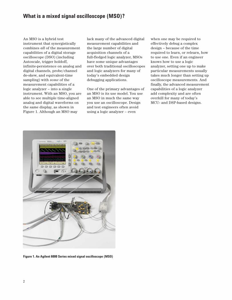
An MSO is a hybrid testinstrument that synergisticallycombines all of the measurementcapabilities of a digital storageoscilloscope (DSO) (includingAutoscale, trigger holdoff,infinite-persistence on analog anddigital channels, probe/channelde-skew, and equivalent-timesampling) with some of themeasurement capabilities of alogic analyzer – into a singleinstrument. With an MSO, you areable to see multiple time-alignedanalog and digital waveforms onthe same display, as shown inFigure 1. Although an MSO may
lack many of the advanced digitalmeasurement capabilities and the large number of digitalacquisition channels of afull-fledged logic analyzer, MSOshave some unique advantagesover both traditional oscilloscopesand logic analyzers for many oftoday’s embedded designdebugging applications.
One of the primary advantages ofan MSO is its use model. You usean MSO in much the same wayyou use an oscilloscope. Designand test engineers often avoidusing a logic analyzer – even
when one may be required toeffectively debug a complexdesign – because of the timerequired to learn, or relearn, howto use one. Even if an engineerknows how to use a logicanalyzer, setting one up to makeparticular measurements usuallytakes much longer than setting uposcilloscope measurements. Andfinally, the advanced measurementcapabilities of a logic analyzeradd complexity and are oftenoverkill for many of today’s MCU- and DSP-based designs.
Figure 1. An Agilent 6000 Series mixed signal oscilloscope (MSO)
3
Oscilloscopes are the mostcommonly used test instrumentsin an R&D environment. Allembedded hardware designengineers should have a basicoperating knowledge of how touse an oscilloscope to makefundamental signal-quality andtiming measurements of theirmixed-signal embedded designs.However, 2- and 4-channeloscilloscope measurements areoften insufficient to monitor andtest critical timing interactionsbetween multiple analog anddigital signals. This is where anMSO proves useful.
Because an MSO provides “just enough” logic analyzermeasurement capability withoutadding too much complexity, it isoften just the right tool fordebugging embedded designs.And as previously mentioned, theuse-model of an MSO is that of an oscilloscope. In fact, an MSOcan simply be thought of as amulti-channel oscilloscope withsome channels (analog) providinglots of vertical resolution(typically 8-bits), with severaladditional channels (logic/digital)
providing low-resolution (1-bit)measurements. A highlyintegrated MSO, as opposed to a loosely tethered two-box,mixed-signal measurementsolution, should be user-friendly,provide fast waveform updaterates, and operate more like an oscilloscope – not like a logic analyzer.
One important characteristic ofall oscilloscopes is waveformupdate rate, which can directlyaffect the usability of aninstrument. Attempting tooperate a scope that is slow andunresponsive can be frustrating,and sluggish response limitsusability. For an instrument’sdisplay and user-controls to lookand feel responsive, waveformupdate rates should be in therange of 20 waveforms per secondor higher. This applies to DSOs aswell as MSOs. This means thatwhen oscilloscope vendors portlogic acquisition channels into aDSO to create an MSO, waveformupdate rates should not besacrificed. Otherwise, thetraditional oscilloscopeuse-model will also be sacrificed.
Mixed-signal measurementsolutions based on two-boxsolutions and/or external logicpods linked via an externalcommunication bus such as USBtend to be very unresponsive anddifficult to use. MSOs based on a highly integrated hardwarearchitecture will tend to be much more responsive and easier to use.
For more detailed informationabout the importance ofwaveform update rates, download Agilent’s ApplicationNote #1551, “Improve YourAbility to Capture Elusive Events:Why Oscilloscope WaveformUpdate Rates are Important,” atwww.agilent.com/find/mso6000.
Although the first step inevaluating which MSO topurchase may be to comparefeatures and measurementperformance in each vendor’sprinted and online literature(data sheets), the only way totruly evaluate the usability andresponsiveness of an instrumentis to actually use it yourself.
What is a mixed signal oscilloscope (MSO)? (continued)
4
Typical MSO measurement applications and required performance
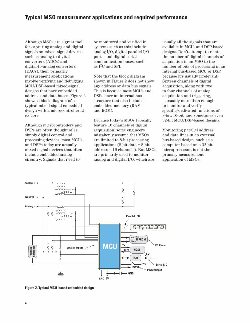
Although MSOs are a great toolfor capturing analog and digitalsignals on mixed-signal devicessuch as analog-to-digitalconverters (ADCs) anddigital-to-analog converters(DACs), their primarilymeasurement applicationsinvolve verifying and debuggingMCU/DSP-based mixed-signaldesigns that have embeddedaddress and data buses. Figure 2shows a block diagram of atypical mixed-signal embeddeddesign with a microcontroller atits core.
Although microcontrollers andDSPs are often thought of assimply digital control andprocessing devices, most MCUsand DSPs today are actuallymixed-signal devices that ofteninclude embedded analogcircuitry. Signals that need to
Volta
geR
efer
ence MCU
EEPROM
HOST
IR-IF
4n
TX
RCV
VccClk
Data
2.5PWM
I2C Comm.
Serial I/O
PWM OutputGND
GND 5V
Parallel I/O
GND
Analog +
Neutral
Analog -
Analog Inputs
be monitored and verified insystems such as this includeanalog I/O, digital parallel I/Oports, and digital serialcommunication buses, such as I2C and SPI.
Note that the block diagramshown in Figure 2 does not showany address or data bus signals.This is because most MCUs andDSPs have an internal busstructure that also includesembedded memory (RAM and ROM).
Because today’s MSOs typicallyfeature 16 channels of digitalacquisition, some engineersmistakenly assume that MSOs are limited to 8-bit processingapplications (8-bit data + 8-bitaddress = 16 channels). But MSOsare primarily used to monitoranalog and digital I/O, which are
usually all the signals that areavailable in MCU- and DSP-baseddesigns. Don’t attempt to relatethe number of digital channels ofacquisition in an MSO to thenumber of bits of processing in aninternal bus-based MCU or DSP,because it’s usually irrelevant.Sixteen channels of digitalacquisition, along with two to four channels of analogacquisition and triggering, is usually more than enough to monitor and verifyspecific/dedicated functions of8-bit, 16-bit, and sometimes even32-bit MCU/DSP-based designs.
Monitoring parallel address and data lines in an externalbus-based design, such as acomputer based on a 32-bitmicroprocessor, is not theprimary measurementapplication of MSOs.
Figure 2. Typical MCU-based embedded design
5
If you need to capture multipleaddress and data bus signals toverify timing and source-codeflow in an external bus-basedsystem, a logic analyzer withstate analysis and disassemblymay be a better measurement toolfor you. And if you also need totime-correlate analog signalsand/or analog characteristics ofdigital signals at the same time,there are two-box solutions(scope + logic analyzer) availablefrom multiple vendors that willimport oscilloscope waveformsinto the logic analyzer with atime-correlated display. But withthis type of higher-performancetwo-box test solution, you mustalso accept the more complex
use-model of a logic analyzerincluding slow or single-shotwaveform update rates.
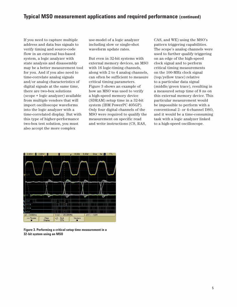
But even in 32-bit systems withexternal memory devices, an MSOwith 16 logic-timing channels,along with 2 to 4 analog channels,can often be sufficient to measurecritical timing parameters.Figure 3 shows an example ofhow an MSO was used to verify a high-speed memory device(SDRAM) setup time in a 32-bitsystem (IBM PowerPC 405GP).Only four digital channels of theMSO were required to qualify themeasurement on specific readand write instructions (CS, RAS,
CAS, and WE) using the MSO’spattern triggering capabilities.The scope’s analog channels wereused to further qualify triggeringon an edge of the high-speedclock signal and to performcritical timing measurements on the 100-MHz clock signal(top/yellow trace) relative to a particular data signal(middle/green trace), resulting ina measured setup time of 8 ns onthis external memory device. Thisparticular measurement would be impossible to perform with aconventional 2- or 4-channel DSO,and it would be a time-consumingtask with a logic analyzer linkedto a high-speed oscilloscope.
Typical MSO measurement applications and required performance (continued)
Figure 3. Performing a critical setup time measurement in a32-bit system using an MSO
6
Typical MSO measurement applications and required performance (continued)
The analog and digital acquisitionperformance of the MSO is moreimportant than the number of channels for these types ofsignal integrity measurements in mixed-signal embeddeddesigns. The most fundamentalspecifications of an oscilloscope’sanalog acquisition performanceare bandwidth and sample rate.For reasonably accurate analogmeasurements, a scope’sbandwidth should be four to fivetimes the highest frequency ofinterest in your signals. Forinstance, if you need to monitor a digital signal with a maximumtoggle/clock frequency of200 MHz with your oscilloscope’sanalog channels, you need ananalog bandwidth of 1 GHz inorder for the scope to capture the fifth harmonic withreasonable accuracy. And for real-time/single-shotmeasurements, the scope’ssample rate should beapproximately four times higherthan the scope’s bandwidth, orfaster. For more detailedinformation about therelationship between a scope’sbandwidth and sample rate,download Agilent’s ApplicationNote #1494, “Advantages andDisadvantages of Using DSPFiltering on OscilloscopeWaveforms,” atwww.agilent.com/find/InfiniiMax.
Unfortunately, some oscilloscopeand logic analyzer users do notfully comprehend the requireddigital acquisition performance of MSOs and logic analyzers. It is important for the digitalacquisition performance of anMSO to be commensurate withthe scope's analog acquisitionperformance. It just doesn’t make sense to combine ahigh-performance oscilloscopewith a low-performancelogic-timing analyzer. Agilentrecommends that an MSO’sdigital/logic acquisition systemprovide sample rates that are at least twice the bandwidth ofthe scope's analog channels ofacquisition. For the example wejust discussed where a 1-GHzoscilloscope is required tocapture analog characteristic ofdigital signals with toggle/clockrates of 200 MHz, capturing thesame signals on the logic/digitalchannels of the MSO withreasonable timing accuracyrequires a 2 GSa/s sample rate on the digital/logic channels.
When you use logic/digitalacquisition channels,measurement resolution islimited to ± one sample period.For example, if you areattempting to capture digitalsignals with a maximumtoggle/clock rate of 200 MHz
(period = 5 ns), each high or lowpulse can be as narrow as 2.5 ns(assuming a 50% duty cycle). Thismeans that if your MSO’s digitalacquisition system samples at amaximum rate of 2 GSa/s, thentiming measurements on eachedge of a pulse can be in error byas much as ± 500 ps producing aworst-case peak-to-peak error of1 ns for delta-time measurements,which is 40% error on a 2.5 nspulse. We believe that exceeding40% timing errors is unacceptablefor digital acquisition channels ofan MSO or logic analyzer, whichis why we recommend that digitalchannel acquisition sample ratesbe at least twice the bandwidth ofthe scope, or higher.
In addition to bandwidth andsample rate, another criticalfactor to consider is probingbandwidth, including both analogand digital system probing.Capturing analog or digitalsignals with significant frequencycontent in excess of 500 MHzrequires active probing on analogchannels. Likewise, digitalacquisition systems must haveprobes that can deliver higherfrequency signals to the digitalsystem’s sampling circuitry inorder to reliably capture everypulse within higher frequencypulse trains.
7
Triggering on mixed signals
More channels of acquisition inan MSO (compared to a DSO)means that you now have moretriggering possibilities in order to zero-in on specific analog anddigital I/O signal interaction.Although an MSO can’t evenbegin to approach the complextriggering capabilities of ahigh-performance logic analyzer,MSO triggering goes far beyond thelimited triggering of a standard 2- or 4-channel oscilloscope.
Most MSOs and mixed-signalmeasurement solutions on themarket today are able to triggeron at least one level of parallelpattern trigger conditions, andsome provide up to two levels ofpattern sequence triggering withreset conditions. But even whenyou use relatively simple one-levelpattern triggering, you will findbig differences in triggeringcapabilities between variousMSOs/mixed-signal measurementsolutions. First of all, it is
important that an MSO is able to trigger on a combination ofanalog and digital inputs. Somemixed-signal measurementsolutions are only able to providetriggering across one side of theacquisition system or the other.In other words, you may only beable to trigger your oscilloscopeon a traditional analog triggercondition, or trigger on just aparallel digital condition – notboth. MSOs should providemixed-signal triggeringcapabilities. The high-speed setup time measurement on the external SDRAM devicepreviously shown in Figure 3illustrates one example wheremixed-signal triggering (analogand digital) is required. Later inthis paper we will show anotherexample where it is necessary totrigger on mixed-signal conditionsin order to synchronize theoscilloscope’s acquisition on aspecific output phase of a DACcontrolled by an MCU.
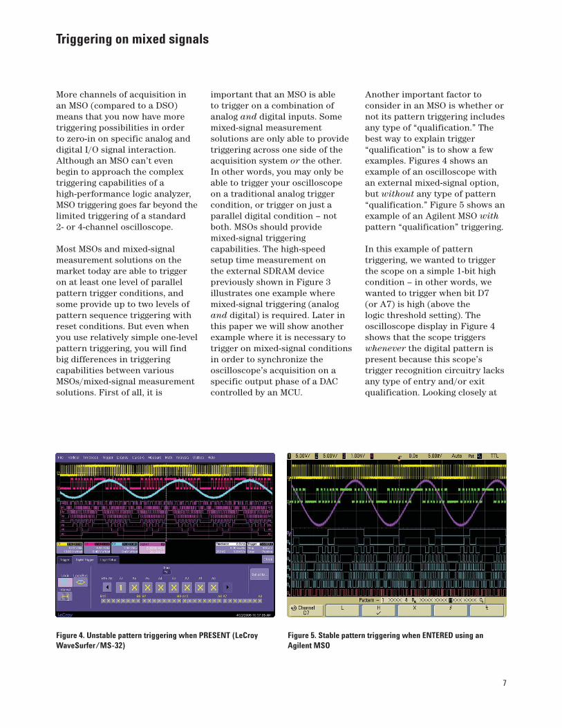
Another important factor toconsider in an MSO is whether ornot its pattern triggering includesany type of “qualification.” Thebest way to explain trigger“qualification” is to show a fewexamples. Figures 4 shows anexample of an oscilloscope withan external mixed-signal option,but without any type of pattern“qualification.” Figure 5 shows anexample of an Agilent MSO withpattern “qualification” triggering.
In this example of patterntriggering, we wanted to triggerthe scope on a simple 1-bit highcondition – in other words, wewanted to trigger when bit D7 (or A7) is high (above the logic threshold setting). Theoscilloscope display in Figure 4shows that the scope triggerswhenever the digital pattern ispresent because this scope’strigger recognition circuitry lacksany type of entry and/or exitqualification. Looking closely at
Figure 4. Unstable pattern triggering when PRESENT (LeCroyWaveSurfer/MS-32)
Figure 5. Stable pattern triggering when ENTERED using anAgilent MSO
8
Triggering on mixed signals (continued)
these screen images, the triggerpoint for both scopes is at thecenter of the display horizontally.The bottom digital trace (A7) inFigure 4 is a high pulse at centerscreen. Unfortunately, the scopetriggers whenever A7 is high,which in this case is during themiddle of this pattern condition.With repetitive acquisitions, it ispossible that this scope couldtrigger at the beginning of thehigh condition, the end of thehigh condition, or anywhere inbetween. The result is an unstabletrigger condition and an unstabledisplay of analog and digitalwaveforms on the scope’s display.Although it is impossible todynamically show this unstabletriggering effect in this paper,when capturing these signalsrepetitively, the displayedwaveforms are not stable, but arejumping around on the scope’sdisplay. This unstable triggeringis unacceptable triggeringperformance for an MSO.
Figure 5 shows the display of an Agilent MSO that includespattern trigger qualificationconditions. Looking closely at thisparticular screen image, note thatwhen D7 (top/blue digital trace)goes high, the scope triggers.Again, the trigger point is atcenter-screen. This MSO’s defaulttrigger qualification is to triggeronly when the specified patterncondition is entered. When thescope is running repetitively, youwill observe stable waveforms onits display. Although the scope’sdefault pattern qualification is totrigger only when the pattern isentered, you are also able tooverride the default selection inorder to specify that the scopetrigger when the pattern isexited, if you want.
There is one more importanttrigger qualification to watch for in MSOs/mixed-signalmeasurement solutions forpattern triggering. In addition
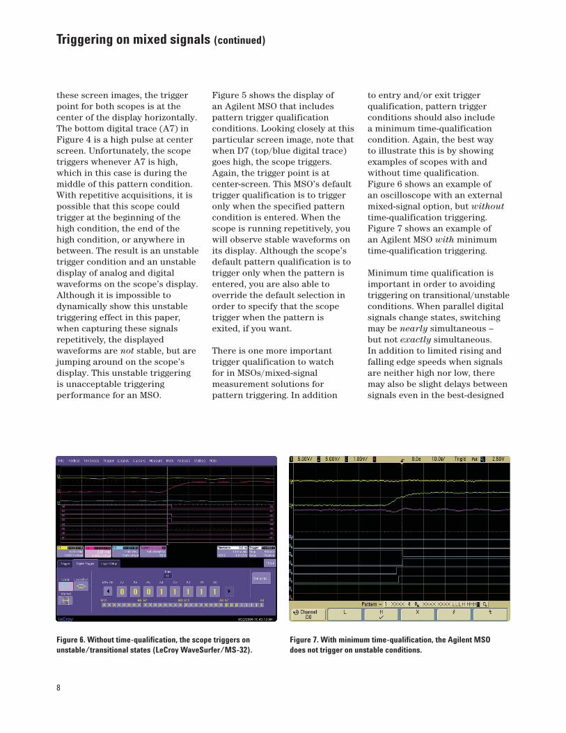
to entry and/or exit triggerqualification, pattern triggerconditions should also include a minimum time-qualificationcondition. Again, the best way to illustrate this is by showingexamples of scopes with andwithout time qualification.Figure 6 shows an example of an oscilloscope with an externalmixed-signal option, but withouttime-qualification triggering.Figure 7 shows an example of an Agilent MSO with minimumtime-qualification triggering.
Minimum time qualification isimportant in order to avoidingtriggering on transitional/unstableconditions. When parallel digitalsignals change states, switchingmay be nearly simultaneous – but not exactly simultaneous. In addition to limited rising andfalling edge speeds when signalsare neither high nor low, theremay also be slight delays betweensignals even in the best-designed
Figure 6. Without time-qualification, the scope triggers onunstable/transitional states (LeCroy WaveSurfer/MS-32).
Figure 7. With minimum time-qualification, the Agilent MSOdoes not trigger on unstable conditions.
9
Triggering on mixed signals (continued)
systems. This means that there willalways be transitional/unstablesignal conditions in your systemwhen signals are switching. Youwill probably want your DSO/MSOor logic analyzer to avoidtriggering on these unstableconditions if possible.
Figure 6 shows an example of an oscilloscope that lackstime-qualification patterntriggering. The scope was set up to trigger on an 8-bit binarypattern: 0001 1111. Lookingclosely at center-screen (thetrigger point), you can see slightdelays between the various digitaltraces (purple). Because of theseslight signal delays, the scopedetects the 0001 1111 pattern forone sample period and triggersthe scope. But this was anunstable/transitional condition.Although the oscilloscope usuallytriggers on the desired stablepattern condition, it sometimestriggers on unstable/transitionalconditions because it lacks anytype of time-qualificationtriggering.
Figure 7 shows an example of an Agilent MSO that includestime-qualification patterntriggering. This oscilloscope isable to reliably trigger on thesame LLLH HHHH parallelpattern condition when thepattern is entered, but only afterthe digital signals have stabilized.This MSO has a default minimumtime-qualification of 2 ns. Inother words, the pattern must bepresent for at least 2 ns beforebeing qualified as a stable triggersource, and then the scope willalways trigger at the beginning(entry point) of the stabilizedpattern. In addition, you canoverride the default setting of >2 ns and select varioustime-qualification conditions,including longer qualificationtimes for slower digital systems.Conversely, if you want the MSOto trigger exclusively on unstableconditions, the scope’s triggerqualification can be set up totrigger only if a pattern is presentfor less than a specified timeincluding patterns that arepresent for less than 2 ns.
Oscilloscopes (including MSOs)have the ability to preciselytrigger at analog triggerlevel/threshold crossing points,while logic analyzers typically use sample-based triggering.Sample-based triggering produces a peak-to-peak triggerjitter/uncertainty of ± one sampleperiod (worst-case peak-to-peakuncertainty = 2 sample periods).By “sample-based triggering,” we mean that the instrumentrandomly samples the inputsignal first, and then establishes a trigger reference point based on sampled data. This type oftriggering, which producessignificant trigger jitter, may besufficient for some typical logicanalyzer measurements, but is unacceptable for eitherconventional oscilloscope or MSO measurements for viewingrepetitive signals.
10
Triggering on mixed signals (continued)
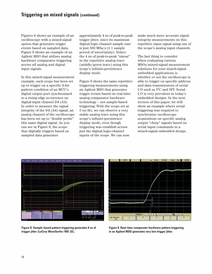
Figures 8 shows an example of anoscilloscope with a mixed-signaloption that generates triggerevents based on sampled data.Figure 9 shows an example of anAgilent MSO that utilizes analoghardware comparator triggeringacross all analog and digital input signals.
In this mixed-signal measurementexample, each scope has been setup to trigger on a specific 8-bitpattern condition of an MCU’sdigital output port synchronizedto a rising edge occurrence ondigital-input channel D4 (A4). In order to measure the signalintegrity of the D4 (A4) signal, ananalog channel of the oscilloscopehas been set up to “double probe”this same digital signal. As youcan see in Figure 8, the scope that digitally triggers based onsampled data generates
approximately 4 ns of peak-to-peaktrigger jitter, since its maximumdigital/logic-channel sample rateis just 500 MSa/s (± 1 sampleperiod of uncertainty). Notice the 4 ns of peak-to-peak “smear”in the repetitive analog trace(middle/green trace) using thisscope’s infinite-persistencedisplay mode.
Figure 9 shows the same repetitivetriggering measurements using an Agilent MSO that generatestrigger events based on real-timeanalog comparator hardwaretechnology – not sample-basedtriggering. With the scope set at5 ns/div, we can observe a verystable analog trace using thisscope’s infinite-persistencedisplay mode, even thoughtriggering was establish acrossjust the digital/logic-channelinputs of the scope. We can now
make much more accurate signalintegrity measurements on thisrepetitive input signal using one ofthe scope’s analog input channels.
The last thing to consider when evaluating variousMSOs/mixed-signal measurementsolutions for your mixed-signalembedded applications iswhether or not the oscilloscope isable to trigger on specific addressand data transmissions of serialI/O such as I2C and SPI. SerialI/O is very prevalent in today’sembedded designs. In the nextsection of this paper, we willshow an example where serialtriggering was required tosynchronize oscilloscopeacquisitions on specific analogoutput “chirp” signals based onserial input commands in amixed-signal embedded design.
Figure 8. Sample-based pattern triggering generates 4 ns oftrigger jitter (LeCroy WaveSurfer/MS-32).
Figure 9. Real-time comparator hardware pattern triggeringin an Agilent MSO generates very low trigger jitter.
11
Turning on and debugging a real mixed-signal embedded design
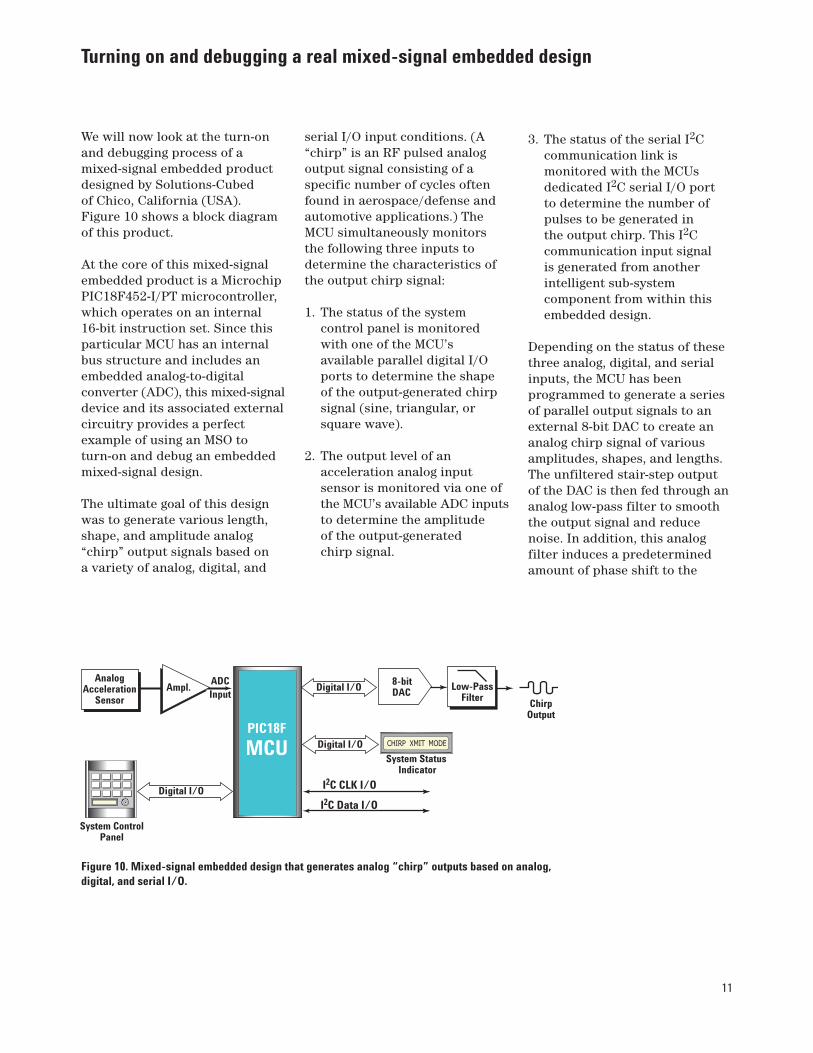
We will now look at the turn-onand debugging process of amixed-signal embedded productdesigned by Solutions-Cubed of Chico, California (USA).Figure 10 shows a block diagramof this product.
At the core of this mixed-signalembedded product is a MicrochipPIC18F452-I/PT microcontroller,which operates on an internal16-bit instruction set. Since thisparticular MCU has an internalbus structure and includes anembedded analog-to-digitalconverter (ADC), this mixed-signaldevice and its associated externalcircuitry provides a perfectexample of using an MSO toturn-on and debug an embeddedmixed-signal design.
The ultimate goal of this designwas to generate various length,shape, and amplitude analog“chirp” output signals based on a variety of analog, digital, and
serial I/O input conditions. (A“chirp” is an RF pulsed analogoutput signal consisting of aspecific number of cycles oftenfound in aerospace/defense andautomotive applications.) TheMCU simultaneously monitors the following three inputs todetermine the characteristics ofthe output chirp signal:
1. The status of the systemcontrol panel is monitoredwith one of the MCU’savailable parallel digital I/Oports to determine the shapeof the output-generated chirpsignal (sine, triangular, orsquare wave).
2. The output level of anacceleration analog inputsensor is monitored via one ofthe MCU’s available ADC inputsto determine the amplitude of the output-generated chirp signal.
3. The status of the serial I2Ccommunication link ismonitored with the MCUsdedicated I2C serial I/O port to determine the number ofpulses to be generated in the output chirp. This I2Ccommunication input signal is generated from anotherintelligent sub-systemcomponent from within thisembedded design.
Depending on the status of thesethree analog, digital, and serialinputs, the MCU has beenprogrammed to generate a seriesof parallel output signals to anexternal 8-bit DAC to create ananalog chirp signal of variousamplitudes, shapes, and lengths.The unfiltered stair-step outputof the DAC is then fed through ananalog low-pass filter to smooththe output signal and reducenoise. In addition, this analogfilter induces a predeterminedamount of phase shift to the
Analog Acceleration
SensorAmpl.
Digital I/O
PIC18F
MCU
System ControlPanel
Digital I/OSystem Status
Indicator
I2C CLK I/O
I2C Data I/O
Digital I/O Low-Pass Filter
8-bitDAC
ChirpOutput
ADC Input
Figure 10. Mixed-signal embedded design that generates analog “chirp” outputs based on analog,digital, and serial I/O.
12
Turning on and debugging a real mixed-signal embedded design (continued)
input signal. Finally, the MCUgenerates a parallel digital outputvia another available digital I/Oport to drive an LCD display thatprovides the user with systemstatus information.
The first step indesigning/programming the MCU in this design was toconfigure the MCU’s I/O for theappropriate number of analogand digital I/O ports. Note thatthe embedded designer cantrade-off the number of analogI/O for digital I/O ports and vice versa in this particularmicrocontroller from MicroChip.
Before attempting to code theMCU to monitor various inputsand generate the final specifiedoutput signals, the design teamdecided it might be best to firstdevelop test code to turn on onesection/function of the product at a time and verify properoperation and signal integrity
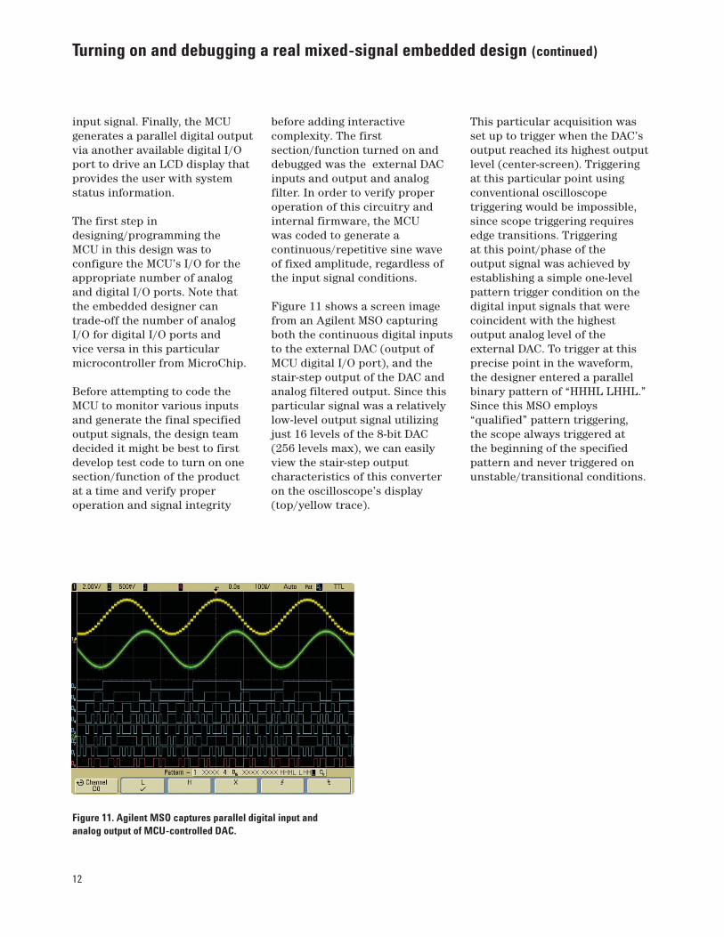
before adding interactivecomplexity. The firstsection/function turned on anddebugged was the external DACinputs and output and analogfilter. In order to verify properoperation of this circuitry andinternal firmware, the MCU was coded to generate acontinuous/repetitive sine waveof fixed amplitude, regardless ofthe input signal conditions.
Figure 11 shows a screen imagefrom an Agilent MSO capturingboth the continuous digital inputsto the external DAC (output ofMCU digital I/O port), and thestair-step output of the DAC andanalog filtered output. Since thisparticular signal was a relativelylow-level output signal utilizingjust 16 levels of the 8-bit DAC(256 levels max), we can easilyview the stair-step outputcharacteristics of this converteron the oscilloscope’s display(top/yellow trace).
This particular acquisition wasset up to trigger when the DAC’soutput reached its highest outputlevel (center-screen). Triggeringat this particular point usingconventional oscilloscopetriggering would be impossible,since scope triggering requiresedge transitions. Triggering at this point/phase of the output signal was achieved byestablishing a simple one-levelpattern trigger condition on thedigital input signals that werecoincident with the highestoutput analog level of theexternal DAC. To trigger at thisprecise point in the waveform,the designer entered a parallelbinary pattern of “HHHL LHHL.”Since this MSO employs“qualified” pattern triggering, the scope always triggered at the beginning of the specifiedpattern and never triggered onunstable/transitional conditions.
Figure 11. Agilent MSO captures parallel digital input andanalog output of MCU-controlled DAC.
13
Turning on and debugging a real mixed-signal embedded design (continued)
Figure 12. Agilent MSO triggers at the 50% crossing point usinga combination of analog AND digital pattern triggering.
Figure 13. Conventional oscilloscope edge triggering fails tosynchronize on specific-length chirps.
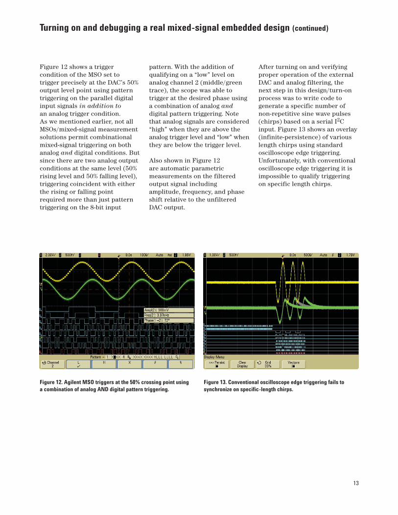
Figure 12 shows a triggercondition of the MSO set totrigger precisely at the DAC’s 50%output level point using patterntriggering on the parallel digitalinput signals in addition toan analog trigger condition. As we mentioned earlier, not allMSOs/mixed-signal measurementsolutions permit combinationalmixed-signal triggering on bothanalog and digital conditions. Butsince there are two analog outputconditions at the same level (50%rising level and 50% falling level),triggering coincident with eitherthe rising or falling pointrequired more than just patterntriggering on the 8-bit input
pattern. With the addition ofqualifying on a “low” level onanalog channel 2 (middle/greentrace), the scope was able totrigger at the desired phase usinga combination of analog anddigital pattern triggering. Notethat analog signals are considered“high” when they are above theanalog trigger level and “low” whenthey are below the trigger level.
Also shown in Figure 12 are automatic parametricmeasurements on the filteredoutput signal includingamplitude, frequency, and phaseshift relative to the unfilteredDAC output.
After turning on and verifyingproper operation of the externalDAC and analog filtering, the next step in this design/turn-onprocess was to write code togenerate a specific number ofnon-repetitive sine wave pulses(chirps) based on a serial I2Cinput. Figure 13 shows an overlay(infinite-persistence) of variouslength chirps using standardoscilloscope edge triggering.Unfortunately, with conventionaloscilloscope edge triggering it isimpossible to qualify triggeringon specific length chirps.
14
Figure 14. Triggering on a 3-cycle chirp with I2C triggeringin an Agilent MSO.
Figure 15. Triggering on a 1-cycle chirp with I2C triggeringin an Agilent MSO.
Turning on and debugging a real mixed-signal embedded design (continued)
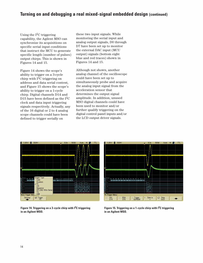
Using the I2C triggeringcapability, the Agilent MSO cansynchronize its acquisitions onspecific serial input conditionsthat instruct the MCU to generatespecific length (number of pulses)output chirps. This is shown inFigures 14 and 15.
Figure 14 shows the scope’sability to trigger on a 3-cyclechirp with I2C triggering onaddress and data serial content,and Figure 15 shows the scope’sability to trigger on a 1-cyclechirp. Digital channels D14 andD15 have been defined as the I2Cclock and data input triggeringsignals respectively. Actually, anyof the 16 digital or 2 to 4 analogscope channels could have beendefined to trigger serially on
these two input signals. Whilemonitoring the serial input andanalog output signals, D0 throughD7 have been set up to monitorthe external DAC input (MCUoutput) signals (bottom eight blue and red traces) shown inFigures 14 and 15.
Although not shown, anotheranalog channel of the oscilloscopecould have been set up tosimultaneously probe and acquirethe analog input signal from theacceleration sensor thatdetermines the output signalamplitude. In addition, unusedMSO digital channels could havebeen used to monitor and/orfurther qualify triggering on thedigital control panel inputs and/orthe LCD output driver signals.
15
Limitation of MSOs
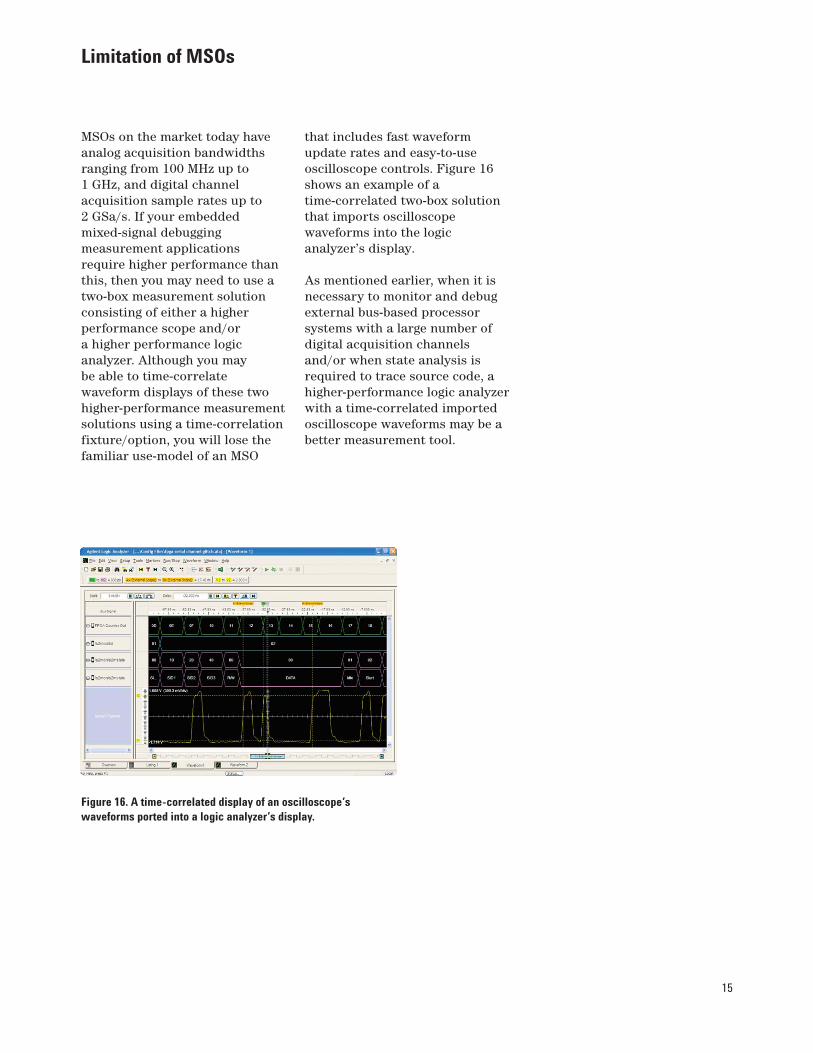
MSOs on the market today haveanalog acquisition bandwidthsranging from 100 MHz up to1 GHz, and digital channelacquisition sample rates up to2 GSa/s. If your embeddedmixed-signal debuggingmeasurement applicationsrequire higher performance thanthis, then you may need to use atwo-box measurement solutionconsisting of either a higherperformance scope and/or a higher performance logicanalyzer. Although you may be able to time-correlatewaveform displays of these twohigher-performance measurementsolutions using a time-correlationfixture/option, you will lose thefamiliar use-model of an MSO
that includes fast waveformupdate rates and easy-to-useoscilloscope controls. Figure 16shows an example of atime-correlated two-box solutionthat imports oscilloscopewaveforms into the logicanalyzer’s display.
As mentioned earlier, when it isnecessary to monitor and debugexternal bus-based processorsystems with a large number ofdigital acquisition channelsand/or when state analysis isrequired to trace source code, ahigher-performance logic analyzerwith a time-correlated importedoscilloscope waveforms may be abetter measurement tool.
Figure 16. A time-correlated display of an oscilloscope’swaveforms ported into a logic analyzer’s display.
16
Summary
Mixed signal oscilloscopes (MSOs)are the new tools-of-choice fordebugging and verifying properoperation of many of today’sMCU- and DSP-basedmixed-signal designs. Withtime-correlated displays of bothanalog and digital waveforms in a single integrated instrument,along with powerful mixed-signaltriggering across all analog anddigital channels, an MSO canoften enable designers to morequickly debug their mixed-signalembedded designs using a familiartool based on an oscilloscope’suser-interface/use-model.
With more MSOs and hybridmixed-signal measurement toolscoming on the market today, it isimportant that you carefullyevaluate the measurementcapabilities and usability of theseinstruments before making apurchase decision. You shouldlook for the following eightcharacteristics:
1. An MSO should operate like afamiliar oscilloscope – not likea logic analyzer.
2. An MSO should have all of the measurement capabilitiesof an oscilloscope withoutsacrificing features such asAutoscale, trigger holdoff,infinite-persistence (on analog and digital channels),probe/channel de-skew, andequivalent-time sampling.
3. An MSO should provide fastwaveform update rates like anoscilloscope – not slowupdates like a logic analyzer.
4. An MSO should havedigital/logic-channelacquisition systemperformance (sample rate and probing bandwidth)commensurate with theperformance of the analogacquisition system of the oscilloscope.
5. An MSO should be able totrigger across both analog anddigital channels (mixed-signaltriggering).
6. An MSO should be able totrigger on pattern conditionsbased on either entry- orexit-qualification conditions inthe pattern – not whenever thepattern is present.
7. An MSO should be able totrigger on patterns based on aminimum qualification time inorder to avoid triggering onunstable/transitional digitalswitching conditions.
8. An MSO should provide both analog and digitaltriggering that is based onreal-time analog comparatortechnology – not sample-basedtriggering which producessignificant trigger jitter onrepetitive analog waveforms.
To view an online videodemonstration of an AgilentMSO6000 series MSO, go towww.agilent.come/find/scope-demo, and then click on the video, “Expanding Beyond Two Dimensions.”
17
Glossary
ADC Analog-to-digital converter, sometimes referred to as an A-to-D
Analog I/O Real-time analog input and output signals of amicrocontroller (MCU) or digital signal processor (DSP)
Chirp An RF-pulsed analog signal consisting of a specific number of pulses
DAC Digital-to-analog converter, sometimes referred to as a D-to-A
Digital I/O Latched input and output signals of a microcontroller(MCU) or digital signal processor (DSP)
DSO Digital storage oscilloscope that acquires and displays analog characteristics of input signals using either real-time orequivalent-time sampling techniques
DSP Digital signal processor
I2C Inter-integrated circuit bus, which is a common 2-wire serial busthat utilizes a self-arbitration protocol
MSO Mixed signal oscilloscope that synergistically combines all of the measurement capabilities of an oscilloscope with some of themeasurement capabilities of a logic analyzer and includes atime-correlated display of both analog and digital waveforms
MCU Microcontroller unit
Qualified pattern triggering Triggering at a specific location within adigital parallel pattern (usually entry or exit points) and ensuring thatan input pattern has stabilized with a minimum time qualification(present for >x time) before generating a trigger event so that the scopeor logic analyzer does not trigger on unstable/transitional inputswitching conditions
RAM Random access memory
Real-time analog hardware comparator triggering Precise triggering thatoccurs before and separate from digital acquisition sampling to insurereliable/stable triggering with minimal trigger uncertainty/jitter
ROM Read-only memory
Sample-based pattern triggering Pattern triggering that is based onsampled data that will induce as much as ± one sample period oftrigger uncertainty/jitter
SDRAM Synchronous dynamic random access memory
SPI Serial protocol interface
18
Related Literature
Publication Title Publication Type Publication Number
Agilent 6000 Series Oscilloscopes Data sheet 5989-2000EN
Agilent 6000 Series Oscilloscope Probes Data sheet 5968-8153ENand Accessories
Agilent 54830 Series Infiniium Oscilloscopes Data sheet 5988-3788EN
Agilent 54830 Series Infiniium Oscilloscopes Data sheet 5968-7141ENProbes and Accessories
Why Oscilloscope Waveform Update Rates Application note 5989-2002ENare Important
Oscilloscope Display Quality Impacts Ability to Application note 5989-2003ENUncover Signal Anomalies – Agilent 6000 Series versus Tek TDS3000B series oscilloscope
Oscilloscope Display Quality Impacts Ability to Application note 5989-2004ENUncover Signal Anomalies - Agilent 6000 Series versus LeCroy WaveSurfer 400 series oscilloscope
Deep Memory Oscilloscopes: The New Tools Application note 5988-9106ENof Choice
Evaluating Oscilloscope Vertical Application note 5989-3020ENNoise Characteristics
Advantages and Disadvantages of Using Application note 5989-1145ENDSP Filtering on Oscilloscope Waveforms
Ten Things to Considers When Selecting Your Application note 5989-0552ENNext Oscilloscope
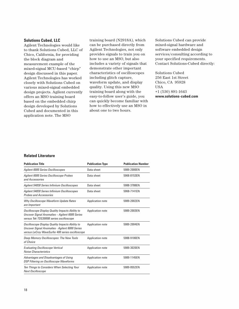
Solutions Cubed, LLCAgilent Technologies would liketo thank Solutions Cubed, LLC ofChico, California, for providingthe block diagram andmeasurement example of themixed-signal MCU-based “chirp”design discussed in this paper.Agilent Technologies has workedclosely with Solutions Cubed onvarious mixed-signal embeddeddesign projects. Agilent currentlyoffers an MSO training boardbased on the embedded chirpdesign developed by SolutionsCubed and documented in thisapplication note. The MSO
training board (N2918A), whichcan be purchased directly fromAgilent Technologies, not onlyprovides signals to train you onhow to use an MSO, but alsoincludes a variety of signals thatdemonstrate other importantcharacteristics of oscilloscopesincluding glitch capture,waveform update, and displayquality. Using this new MSOtraining board along with theeasy-to-follow user’s guide, youcan quickly become familiar withhow to effectively use an MSO inabout one to two hours.
Solutions Cubed can providemixed-signal hardware andsoftware embedded designservices/consulting according toyour specified requirements.Contact Solutions-Cubed directly:
Solutions Cubed256 East 1st StreetChico, CA 95928USA+1 (530) 891-1643www.solutions-cubed.com
Agilent Technologies’ Test and Measurement Support, Services, and AssistanceAgilent Technologies aims to maximize the value you receive, while minimizing your risk andproblems. We strive to ensure that you get the test and measurement capabilities you paidfor and obtain the support you need. Our extensive support resources and services can helpyou choose the right Agilent products for your applications and apply them successfully.Every instrument and system we sell has a global warranty. Two concepts underlie Agilent’soverall support policy: “Our Promise” and “Your Advantage.”
Our PromiseOur Promise means your Agilent test and measurement equipment will meet its advertisedperformance and functionality. When you are choosing new equipment, we will help youwith product information, including realistic performance specifications and practicalrecommendations from experienced test engineers. When you receive your new Agilentequipment, we can help verify that it works properly and help with initial product operation.
Your AdvantageYour Advantage means that Agilent offers a wide range of additional expert test andmeasurement services, which you can purchase according to your unique technical andbusiness needs. Solve problems efficiently and gain a competitive edge by contracting withus for calibration, extra-cost upgrades, out-of-warranty repairs, and on-site education andtraining, as well as design, system integration, project management, and other professionalengineering services. Experienced Agilent engineers and technicians worldwide can help you maximize your productivity, optimize the return on investment of your Agilentinstruments and systems, and obtain dependable measurement accuracy for the life ofthose products.
For more information on Agilent Technologies’products, applications or services, pleasecontact your local Agilent office. The completelist is available at:
www.agilent.com/find/contactus
Phone or FaxUnited States:(tel) 800 829 4444(fax) 800 829 4433
Canada:(tel) 877 894 4414(fax) 800 746 4866
China:(tel) 800 810 0189(fax) 800 820 2816
Europe:(tel) 31 20 547 2111
Japan:(tel) (81) 426 56 7832(fax) (81) 426 56 7840
Korea:(tel) (080) 769 0800(fax) (080) 769 0900
Latin America:(tel) (305) 269 7500
Taiwan:(tel) 0800 047 866(fax) 0800 286 331
Other Asia Pacific Countries:(tel) (65) 6375 8100(fax) (65) 6755 0042Email: [email protected] revised: 05/27/05
Product specifications and descriptions in thisdocument subject to change without notice.
© Agilent Technologies, Inc. 2005Printed in USA, August 19, 2005
5989-3702EN
Agilent Email Updates
www.agilent.com/find/emailupdatesGet the latest information on the products and applications you select.
www.agilent.com
Agilent Direct
www.agilent.com/find/agilentdirectQuickly choose and use your test equipment solutions with confidence.
Agilent Open
www.agilent.com/find/openAgilent Open simplifies the process of connecting and programming test systems to help engineers design, validate and manufacture electronic products. Agilent offers openconnectivity for a broad range of system-ready instruments, open industry software,PC-standard I/O and global support, which are combined to more easily integrate testsystem development.