decarburisation rates in rh–ktb degasser of cst steel ...steelcast.ru/d/80122/d/rh-ktb.pdf · cst...
TRANSCRIPT
Pub
lishe
d by
Man
ey P
ublis
hing
(c)
IOM
Com
mun
icat
ions
Ltd
Decarburisation rates in RHndashKTB degasser ofCST steel plant through physical modellingstudy
V Seshadri1 C A da Silva2 I A da Silva2 G A Vargas3 andP S B Lascosqui3
A physical model based on similarity principles was constructed to simulate the RH (Ruhrstahlndash
Heraeus) degasser of CST (Companhia Siderurgica Tubarao Vitoria Brazil) to evaluate the
influence of metal circulation rate which essentially defines the degree of exposure of the metal to
the vacuum in the chamber on the decarburisation rate The circulation rate in addition influences
the removal of dissolved gases such as nitrogen and hence it is essential to optimise this
parameter to achieve maximum refining efficiency with minimum refining time thus improving the
productivity of the secondary refining process In the present work simulation experiments
investigating the kinetics of decarburisation have been carried out using the CO2 adsorptionndash
desorption process in sodium hydroxide solution as the circulating fluid The effect of bottom gas
flowrate and snorkel diameter in this case was also evaluated Bottom gas injection practice
under the upleg improves the circulation rate Increasing the circulation rate by bottom injection
leads to an increased degassing rate However degasification efficiency does not remain at the
same level The circulation and degasification rates can be improved by an increase in diameter
of the downleg snorkel The relative gain in degasification seems to be higher at the higher
flowrate range The results have been translated to a prototype to optimise the process
Keywords RH degasser Decarburisation Physical modelling
IntroductionThe RH (RuhrstahlndashHeraeus) degassing process iswidely used for the secondary refining of steel includingdecarburisation the removal of nitrogen hydrogeninclusions etc and alloy additions and so on can be canbe made with efficiency depending upon the specificationof the final product During RH treatment molten steelis circulated between the vacuum vessel and the ladleand as such the circulation rate as well as stirring effectshave an important influence on the rate of degassing inaddition to the degree of vacuum These in turn aredependent on the gas injection rate through the nozzlesdepth of injection inside diameter morphology lengthand number of snorkels amount of hot metal in theladle and the temperature As well as these parametersoperating problems such as nozzle blockage have asignificant influence on the circulation rate Severalstudies have highlighted the effects of various
parameters on the circulation rate and mixing timesuch as snorkel diameter argon gas flowrate etc usingtracers such as potassium chloride1ndash3 Circulation rateshave also been measured using radioisotopes4 Thegeneral conclusions of these investigations are that thecirculation rate increases with increasing inner diameterof the upleg and gas flowrate5 which in turn results inbetter degassing rates Generally speaking the main goalis to reduce the tapndashtap time in order to synchronisebetter the degassing operation and casting Models bothmacroscopic and microscopic are available in theliterature differing in detail but generally in agreementwith the idea that refining is faster when the circulationrates are greater In one of the macroscopic models6 therate of decarburisation is given by
lnCf
Ci
~KCt (1)
where Cf and Ci represent the final and initial carbonconcentrations respectively t is the time (min) and KC isa kinetic parameter relating to decarburisation (min21)On the other hand KC would be dependent on thecirculation rate according to
KC ~Q
rV
q
Q=reth THORNzq(2)
1Department of Metallurgical Engineering and Materials UniversidadeFederal de Minas Gerais (UFMG) Belo Horizonte Brazil2Department of Metallurgical and Materials Engineering UniversidadeFederal de Ouro Preto (UFOP) Ouro Preto Brazil3Companhia Siderurgica de Tubarao (CST) Vitoria Brazil
Corresponding author email seshadridemetufmgbr
34
2006 Institute of Materials Minerals and MiningPublished by Maney on behalf of the InstituteReceived 14 December 2004 accepted 15 August 2005DOI 101179174328106X80019 Ironmaking and Steelmaking 2006 VOL 33 NO 1
Pub
lishe
d by
Man
ey P
ublis
hing
(c)
IOM
Com
mun
icat
ions
Ltd
where Q is the circulation rate (kg min21) V is thevolume of steel in the ladle (m3) r is the steel specificgravity (kg m23) and q is a volumetric mass transfercoefficient (m3 min21) The last parameter is timedependent and can be evaluated from6
q~026Q064 AvC (3)
where Av is the vacuum chamber cross-sectional area(m2)
Another model7 is based on the assumption that arefining reaction such as decarburisation takes place atthe surface of bubbles rising in the upleg and at thesurface of droplets ejected by vigorous stirring as well asat the surface of liquid in the vacuum chamber The lastmentioned contribution is given by
dC
dt~
F
Vk(CCe) (4)
where C and Ce represent the instantaneous andequilibrium compositions F is the area of the effectivereaction interface V is the volume of the bath inside thevacuum chamber and k is a mass transfer coefficientThe parameter k can be evaluated from penetrationtheory using the velocity of molten steel at the uplegoutlet During the integration process this contributionmust be evaluated for a time interval equal to theresidence time of metal inside the chamber As far as theshop floor is concerned an appropriate combinationbetween deep vacuum and high circulation rate wouldguarantee that the requirements for composition andproductivity are met For evaluating the residence timeof the metal inside the vacuum chamber the circulationrate is required
In the present work the effect of gas injection througha porous plug on circulation rates and carbon removal forthe conditions of operation of the RH degassing unit ofCST (Companhia Siderurgica Tubarao Vitoria Brazil)steel plant has been studied through physical modellingThe objective is to assess whether the circulation anddegassing rates can be improved in order to shortentreatment times without compromising quality
MethodologyThe water model of the RH unit of CST was constructed(in acrylic) with a scale factor of 15 consideringgeometric and dynamic similarity criteria based onReynolds and Froude numbers as well as proportionalflows of gas and liquid in the system These dimensionalgroups had been considered with success in a previoussimulation carried out with the RH degassing units oftwo steel plants in Brazil7 where correlations betweendimensionless groups were evaluated for the model andthen translated to the industrial process In a recentphysical modelling study8 fluid flow and mixingcharacteristics as well as influence of bottom gasinjection and nozzle blockage of the RH degassing unitof the CST steel plant were investigated The watermodel used in the present work was practically the sameas that used in the above study Table 1 lists operationaland geometric parameters of the prototype and thecorresponding values obtained by applying similarityprinciples for the physical model
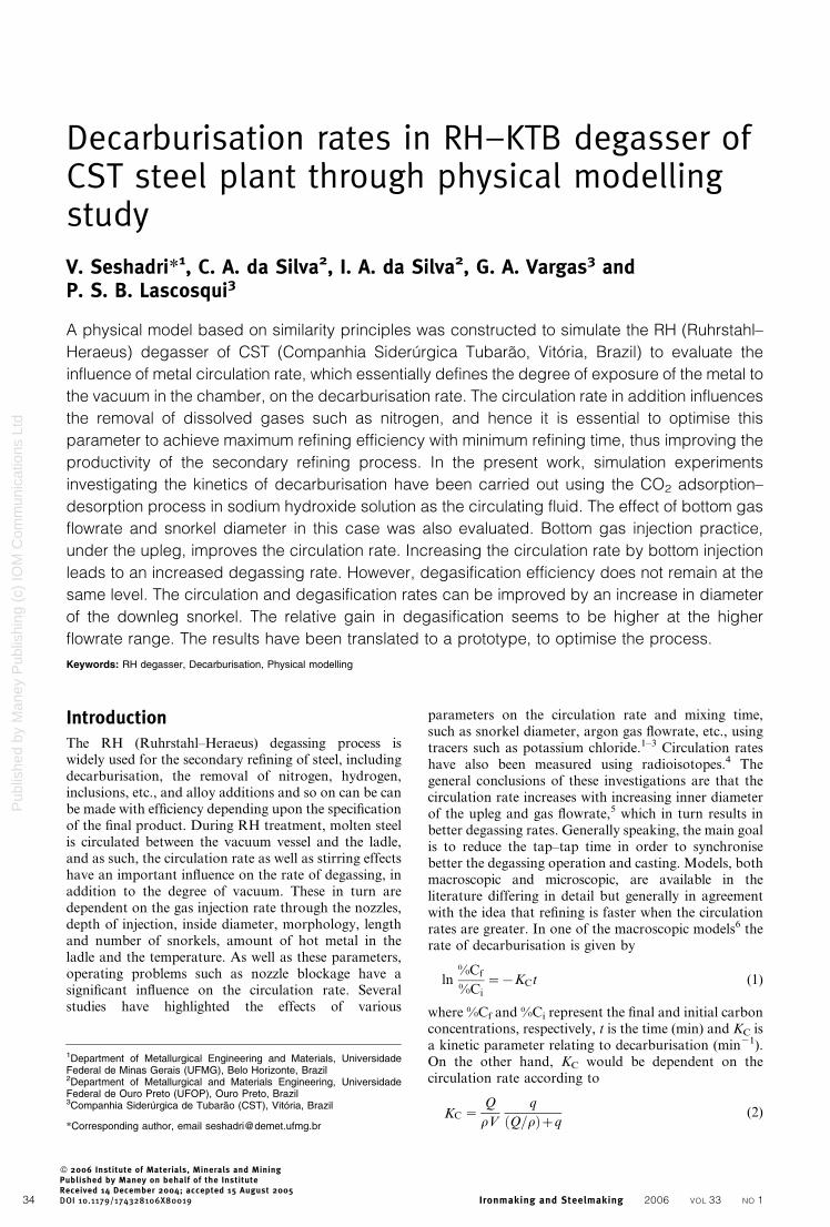
Figure 1 illustrates the experimental setup Thevacuum vessel was equipped with two snorkels and 16nozzles in the upleg (two levels) Air was used forinjection through the nozzles The upleg and downlegdiameters were 150 mm snorkel immersion depth was60 mm and liquid level in the vacuum vessel 65 mmThese are basic data for standard operation Most werevaried during the experiments in order to assess theirinfluence upon operation The air flowrates actually usedfell short of the estimated maximum air flowrates in themodel namely 600 L min21 (STP) It was noted thatentrapped air was drawn downwards in the downleg atflowrates above 300 L min21 (STP)
Circulation was studied using potassium chloridesolution as tracer and conductivity measurements toevaluate tracer concentration with time Air was injectedthrough the nozzles as well as the bottom of the ladle(under the upleg) For each operational conditionsimulated changes in composition were measured inthe downleg by means of a conductivity meter The
Table 1 Parameters of industrial RH (RuhrstahlndashHeraeus) degasser unit and physical model
Parameters Prototype Model
General Vacuum level mbar 067 984Working temperature uC 1560 25Fluid Steel WaterLiquid specific gravity kg m23 7000 1000
Vessel Internal diameter mm 2245 449Length mm 7600 65
Snorkels Length mm 1820 364Internal diameter mm 750 150Distance between longitudinal axes mm 1540 165Depth of immersion mm 450 90
Gas injection system Gas Argon AirFlowrate NL min21 2500 600Gas specific gravity kg m23 013 1123Distance between injection levels mm 175 35Nozzle diameter mm 8 16
Ladle Volume of liquid m3 45 0360Upper internal diameter mm 4200 840Lower internal diameter mm 3650 730Height mm 4420 880Liquid level mm 3650 730Freeboard mm 600 120
Height necessary for lifting water level depending on application of vacuum in vacuum chamber
Seshadri et al Decarburisation rates in RHndashKTB degasser
Ironmaking and Steelmaking 2006 VOL 33 NO 1 35
Pub
lishe
d by
Man
ey P
ublis
hing
(c)
IOM
Com
mun
icat
ions
Ltd
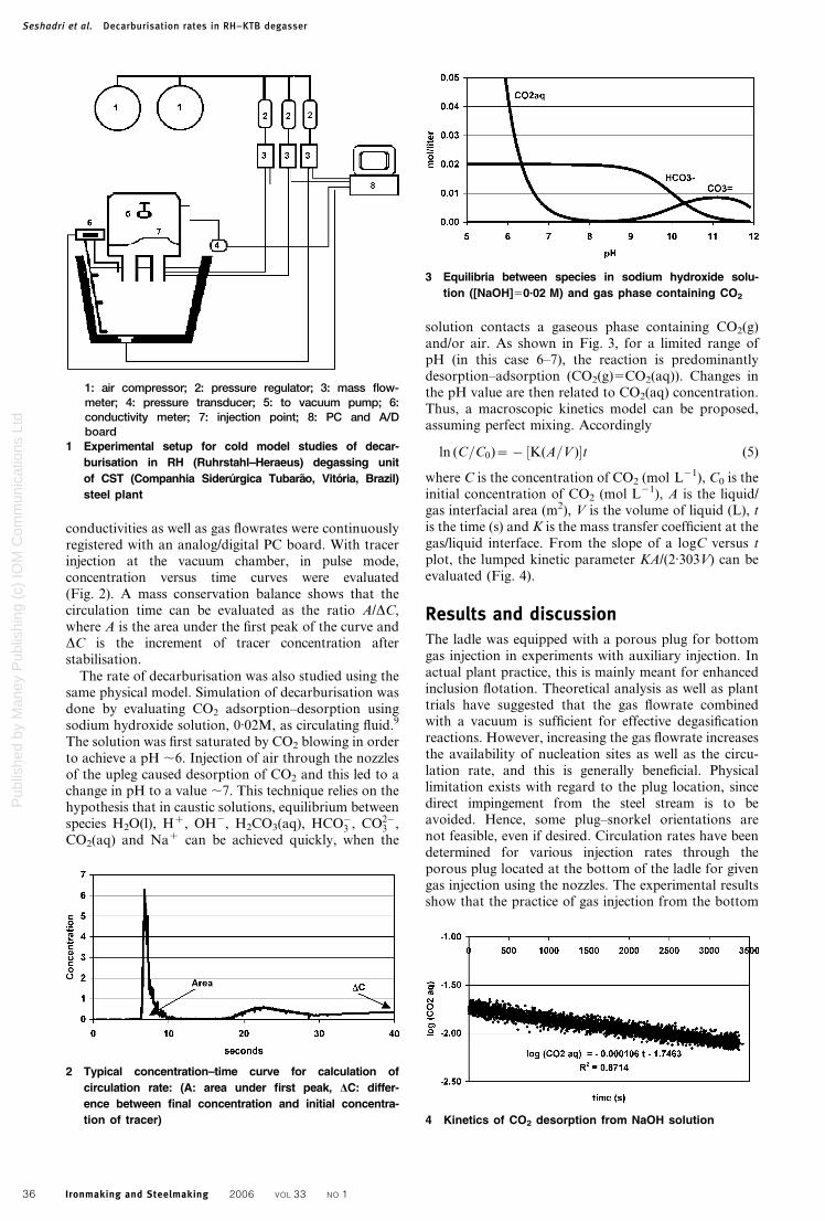
conductivities as well as gas flowrates were continuouslyregistered with an analogdigital PC board With tracerinjection at the vacuum chamber in pulse modeconcentration versus time curves were evaluated(Fig 2) A mass conservation balance shows that thecirculation time can be evaluated as the ratio ADCwhere A is the area under the first peak of the curve andDC is the increment of tracer concentration afterstabilisation
The rate of decarburisation was also studied using thesame physical model Simulation of decarburisation wasdone by evaluating CO2 adsorptionndashdesorption usingsodium hydroxide solution 002M as circulating fluid9
The solution was first saturated by CO2 blowing in orderto achieve a pH 6 Injection of air through the nozzlesof the upleg caused desorption of CO2 and this led to achange in pH to a value 7 This technique relies on thehypothesis that in caustic solutions equilibrium betweenspecies H2O(l) Hz OH2 H2CO3(aq) HCO
3 CO23
CO2(aq) and Naz can be achieved quickly when the
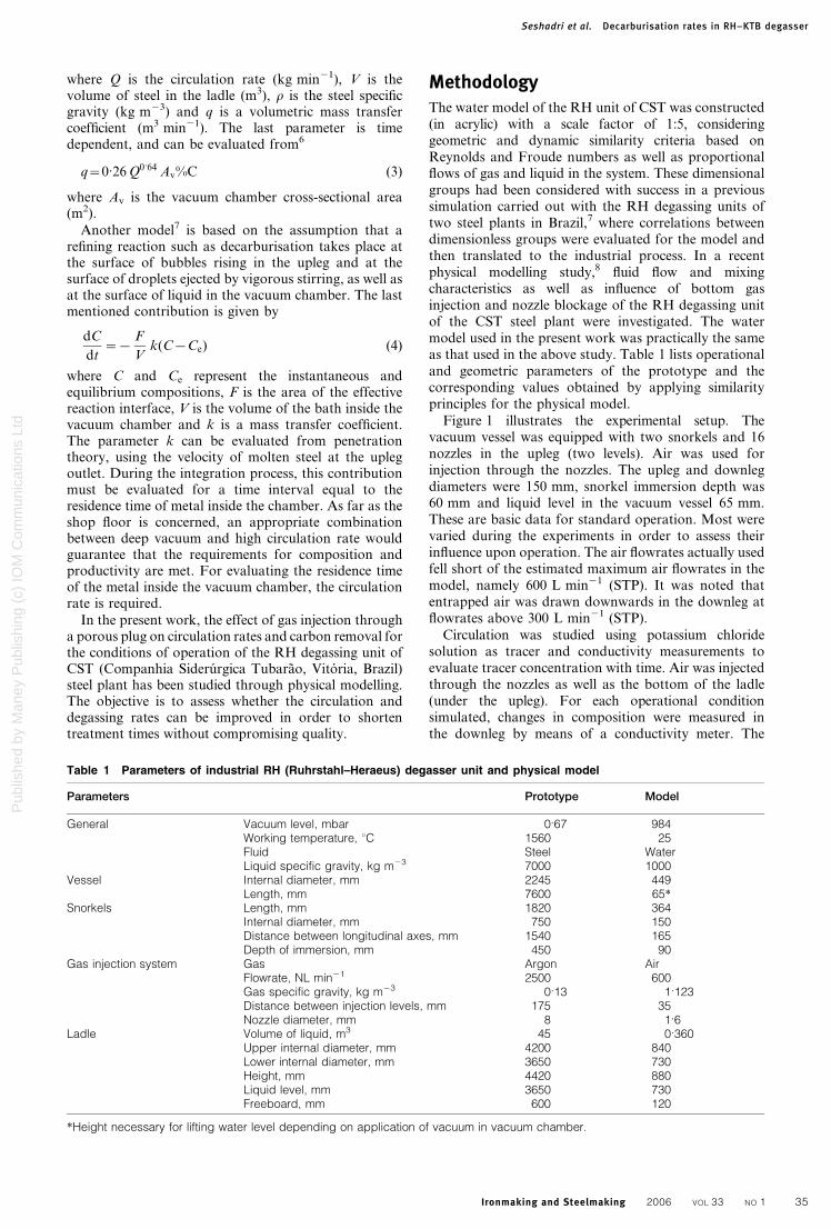
solution contacts a gaseous phase containing CO2(g)andor air As shown in Fig 3 for a limited range ofpH (in this case 6ndash7) the reaction is predominantlydesorptionndashadsorption (CO2(g)5CO2(aq)) Changes inthe pH value are then related to CO2(aq) concentrationThus a macroscopic kinetics model can be proposedassuming perfect mixing Accordingly
ln (C=C0)~ frac12K(A=V )t (5)
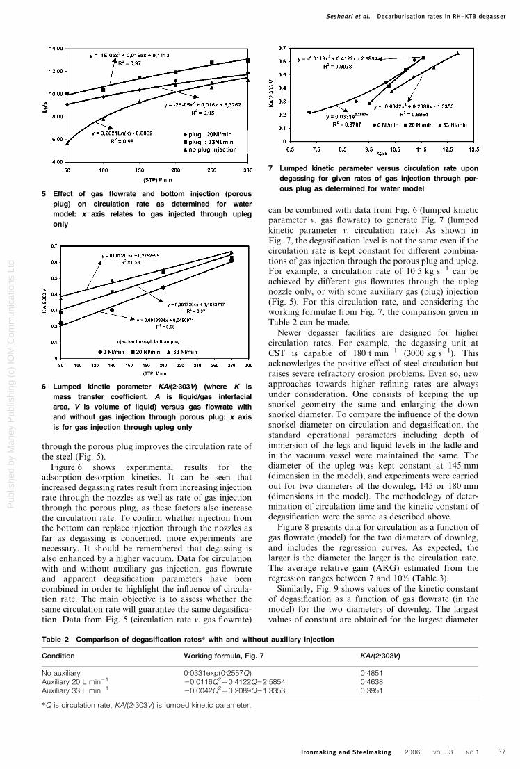
where C is the concentration of CO2 (mol L21) C0 is theinitial concentration of CO2 (mol L21) A is the liquidgas interfacial area (m2) V is the volume of liquid (L) tis the time (s) and K is the mass transfer coefficient at thegasliquid interface From the slope of a logC versus tplot the lumped kinetic parameter KA(2303V) can beevaluated (Fig 4)
Results and discussionThe ladle was equipped with a porous plug for bottomgas injection in experiments with auxiliary injection Inactual plant practice this is mainly meant for enhancedinclusion flotation Theoretical analysis as well as planttrials have suggested that the gas flowrate combinedwith a vacuum is sufficient for effective degasificationreactions However increasing the gas flowrate increasesthe availability of nucleation sites as well as the circu-lation rate and this is generally beneficial Physicallimitation exists with regard to the plug location sincedirect impingement from the steel stream is to beavoided Hence some plugndashsnorkel orientations arenot feasible even if desired Circulation rates have beendetermined for various injection rates through theporous plug located at the bottom of the ladle for givengas injection using the nozzles The experimental resultsshow that the practice of gas injection from the bottom
2 Typical concentrationndashtime curve for calculation of
circulation rate (A area under first peak DC differ-
ence between final concentration and initial concentra-
tion of tracer)
3 Equilibria between species in sodium hydroxide solu-
tion ([NaOH]5002 M) and gas phase containing CO2
1 air compressor 2 pressure regulator 3 mass flow-meter 4 pressure transducer 5 to vacuum pump 6conductivity meter 7 injection point 8 PC and ADboard
1 Experimental setup for cold model studies of decar-
burisation in RH (RuhrstahlndashHeraeus) degassing unit
of CST (Companhia Siderurgica Tubarao Vitoria Brazil)
steel plant
4 Kinetics of CO2 desorption from NaOH solution
Seshadri et al Decarburisation rates in RHndashKTB degasser
36 Ironmaking and Steelmaking 2006 VOL 33 NO 1
Pub
lishe
d by
Man
ey P
ublis
hing
(c)
IOM
Com
mun
icat
ions
Ltd
through the porous plug improves the circulation rate ofthe steel (Fig 5)
Figure 6 shows experimental results for theadsorptionndashdesorption kinetics It can be seen thatincreased degassing rates result from increasing injectionrate through the nozzles as well as rate of gas injectionthrough the porous plug as these factors also increasethe circulation rate To confirm whether injection fromthe bottom can replace injection through the nozzles asfar as degassing is concerned more experiments arenecessary It should be remembered that degassing isalso enhanced by a higher vacuum Data for circulationwith and without auxiliary gas injection gas flowrateand apparent degasification parameters have beencombined in order to highlight the influence of circula-tion rate The main objective is to assess whether thesame circulation rate will guarantee the same degasifica-tion Data from Fig 5 (circulation rate v gas flowrate)
can be combined with data from Fig 6 (lumped kineticparameter v gas flowrate) to generate Fig 7 (lumpedkinetic parameter v circulation rate) As shown inFig 7 the degasification level is not the same even if thecirculation rate is kept constant for different combina-tions of gas injection through the porous plug and uplegFor example a circulation rate of 105 kg s21 can beachieved by different gas flowrates through the uplegnozzle only or with some auxiliary gas (plug) injection(Fig 5) For this circulation rate and considering theworking formulae from Fig 7 the comparison given inTable 2 can be made
Newer degasser facilities are designed for highercirculation rates For example the degassing unit atCST is capable of 180 t min21 (3000 kg s21) Thisacknowledges the positive effect of steel circulation butraises severe refractory erosion problems Even so newapproaches towards higher refining rates are alwaysunder consideration One consists of keeping the upsnorkel geometry the same and enlarging the downsnorkel diameter To compare the influence of the downsnorkel diameter on circulation and degasification thestandard operational parameters including depth ofimmersion of the legs and liquid levels in the ladle andin the vacuum vessel were maintained the same Thediameter of the upleg was kept constant at 145 mm(dimension in the model) and experiments were carriedout for two diameters of the downleg 145 or 180 mm(dimensions in the model) The methodology of deter-mination of circulation time and the kinetic constant ofdegasification were the same as described above
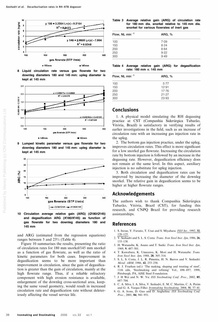
Figure 8 presents data for circulation as a function ofgas flowrate (model) for the two diameters of downlegand includes the regression curves As expected thelarger is the diameter the larger is the circulation rateThe average relative gain (ARG) estimated from theregression ranges between 7 and 10 (Table 3)
Similarly Fig 9 shows values of the kinetic constantof degasification as a function of gas flowrate (in themodel) for the two diameters of downleg The largestvalues of constant are obtained for the largest diameter
5 Effect of gas flowrate and bottom injection (porous
plug) on circulation rate as determined for water
model x axis relates to gas injected through upleg
only
Table 2 Comparison of degasification rates with and without auxiliary injection
Condition Working formula Fig 7 KA(2303V)
No auxiliary 00331exp(02557Q) 04851Auxiliary 20 L min21 200116Q2z04122Q225854 04638Auxiliary 33 L min21 200042Q2z02089Q213353 03951
Q is circulation rate KA(2303V) is lumped kinetic parameter
6 Lumped kinetic parameter KA(2303V) (where K is
mass transfer coefficient A is liquidgas interfacial
area V is volume of liquid) versus gas flowrate with
and without gas injection through porous plug x axis
is for gas injection through upleg only
7 Lumped kinetic parameter versus circulation rate upon
degassing for given rates of gas injection through por-
ous plug as determined for water model
Seshadri et al Decarburisation rates in RHndashKTB degasser
Ironmaking and Steelmaking 2006 VOL 33 NO 1 37
Pub
lishe
d by
Man
ey P
ublis
hing
(c)
IOM
Com
mun
icat
ions
Ltd
and ARG (estimated from the regression equations)ranges between 5 and 23 (Table 4)
Figure 10 summarises the results presenting the ratioof circulation rates for 180 mm snorkel145 mm snorkelas a function of gas flowrate as well as the ratio ofkinetic parameters for both cases Improvement indegasification seems to be more important thanimprovement in circulation since the gain of degasifica-tion is greater than the gain of circulation mainly at thehigh flowrate range Thus if a reliable refractorycomponent with high erosion resistance is availableenlargement of the downleg cross-sectional area keep-ing the same vessel geometry would result in increasedcirculation rate and degasification rate without deleter-iously affecting the vessel service life
Conclusions1 A physical model simulating the RH degassing
practice at CST (Companhia Siderurgica TubaraoVitoria Brazil) is satisfactory in verifying results ofearlier investigations in the field such as an increase ofcirculation rate with an increasing gas injection rate inthe upleg
2 The bottom gas injection practice under the uplegimproves circulation rates This effect is more significantfor a low snorkel gas flowrate Increasing the circulationrate by bottom injection is followed by an increase in thedegassing rate However degasification efficiency doesnot remain at the same level In this aspect auxiliaryinjection is no substitute for upleg injection
3 Both circulation and degasification rates can beimproved by increasing the diameter of the downlegsnorkel The relative gain in degasification seems to behigher at higher flowrate ranges
Acknowledgements
The authors wish to thank Companhia SiderurgicaTubarao Vitoria Brazil (CST) for funding thisresearch and CNPQ Brazil for providing researchassistantships
References1 S Inoue Y Furuno T Usui and S Miyahara ISIJ Int 1992 32
120ndash125
2 V Seshadri and S L S Costa Trans Iron Steel Inst Jpn 1986 26
133ndash138
3 H Watanabe K Asano and T Saeki Trans Iron Steel Inst Jpn
1969 9 487ndash501
4 T Kuwabara K Umezawa K Mori and H Watanabe Trans
Iron Steel Inst Jpn 1988 28 305ndash314
5 S L S Costa J L R Pimenta H N Barros and V Seshadri
Metal ABM 1986 42 253ndash256
6 R J Fruehan (ed) lsquoThe making shaping and treating of steelrsquo
11th edn lsquoSteelmaking and refiningrsquo Vol 696ndash697 1998
Pittsburgh PA AISE Steel Foundation
7 J H Wei and N W Yu ISS Steelmaking Conf Proc 2002 85
687ndash704
8 C A Silva I A Silva V Seshadri E M C Martins C A Perim
and G A Vargas Filho Ironmaking Steelmaking 2004 31 37ndash41
9 G A Irons D Guo and D Anghelina ISS Steelmaking Conf
Proc 2001 84 941ndash951
9 Lumped kinetic parameter versus gas flowrate for two
downleg diameters 180 and 145 mm upleg diameter is
kept at 145 mm
8 Liquid circulation rate versus gas flowrate for two
downleg diameters 180 and 145 mm upleg diameter is
kept at 145 mm
10 Circulation average relative gain (ARG) (Q180Q145)
and degasification ARG (K180K145) as function of
gas flowrate for two downleg diameters 180 and
145 mm
Table 3 Average relative gain (ARG) of circulation ratefor 180 mm dia snorkel relative to 145 mm diasnorkel for various flowrates of inert gas
Flow NL min21 ARG
100 709150 824200 884250 922300 949
Table 4 Average relative gain (ARG) for degasificationrate 180 mm v 145 mm
Flow NL min21 ARG
100 577150 1291200 1776250 2127300 2393
Seshadri et al Decarburisation rates in RHndashKTB degasser
38 Ironmaking and Steelmaking 2006 VOL 33 NO 1
Pub
lishe
d by
Man
ey P
ublis
hing
(c)
IOM
Com
mun
icat
ions
Ltd
where Q is the circulation rate (kg min21) V is thevolume of steel in the ladle (m3) r is the steel specificgravity (kg m23) and q is a volumetric mass transfercoefficient (m3 min21) The last parameter is timedependent and can be evaluated from6
q~026Q064 AvC (3)
where Av is the vacuum chamber cross-sectional area(m2)
Another model7 is based on the assumption that arefining reaction such as decarburisation takes place atthe surface of bubbles rising in the upleg and at thesurface of droplets ejected by vigorous stirring as well asat the surface of liquid in the vacuum chamber The lastmentioned contribution is given by
dC
dt~
F
Vk(CCe) (4)
where C and Ce represent the instantaneous andequilibrium compositions F is the area of the effectivereaction interface V is the volume of the bath inside thevacuum chamber and k is a mass transfer coefficientThe parameter k can be evaluated from penetrationtheory using the velocity of molten steel at the uplegoutlet During the integration process this contributionmust be evaluated for a time interval equal to theresidence time of metal inside the chamber As far as theshop floor is concerned an appropriate combinationbetween deep vacuum and high circulation rate wouldguarantee that the requirements for composition andproductivity are met For evaluating the residence timeof the metal inside the vacuum chamber the circulationrate is required
In the present work the effect of gas injection througha porous plug on circulation rates and carbon removal forthe conditions of operation of the RH degassing unit ofCST (Companhia Siderurgica Tubarao Vitoria Brazil)steel plant has been studied through physical modellingThe objective is to assess whether the circulation anddegassing rates can be improved in order to shortentreatment times without compromising quality
MethodologyThe water model of the RH unit of CST was constructed(in acrylic) with a scale factor of 15 consideringgeometric and dynamic similarity criteria based onReynolds and Froude numbers as well as proportionalflows of gas and liquid in the system These dimensionalgroups had been considered with success in a previoussimulation carried out with the RH degassing units oftwo steel plants in Brazil7 where correlations betweendimensionless groups were evaluated for the model andthen translated to the industrial process In a recentphysical modelling study8 fluid flow and mixingcharacteristics as well as influence of bottom gasinjection and nozzle blockage of the RH degassing unitof the CST steel plant were investigated The watermodel used in the present work was practically the sameas that used in the above study Table 1 lists operationaland geometric parameters of the prototype and thecorresponding values obtained by applying similarityprinciples for the physical model
Figure 1 illustrates the experimental setup Thevacuum vessel was equipped with two snorkels and 16nozzles in the upleg (two levels) Air was used forinjection through the nozzles The upleg and downlegdiameters were 150 mm snorkel immersion depth was60 mm and liquid level in the vacuum vessel 65 mmThese are basic data for standard operation Most werevaried during the experiments in order to assess theirinfluence upon operation The air flowrates actually usedfell short of the estimated maximum air flowrates in themodel namely 600 L min21 (STP) It was noted thatentrapped air was drawn downwards in the downleg atflowrates above 300 L min21 (STP)
Circulation was studied using potassium chloridesolution as tracer and conductivity measurements toevaluate tracer concentration with time Air was injectedthrough the nozzles as well as the bottom of the ladle(under the upleg) For each operational conditionsimulated changes in composition were measured inthe downleg by means of a conductivity meter The
Table 1 Parameters of industrial RH (RuhrstahlndashHeraeus) degasser unit and physical model
Parameters Prototype Model
General Vacuum level mbar 067 984Working temperature uC 1560 25Fluid Steel WaterLiquid specific gravity kg m23 7000 1000
Vessel Internal diameter mm 2245 449Length mm 7600 65
Snorkels Length mm 1820 364Internal diameter mm 750 150Distance between longitudinal axes mm 1540 165Depth of immersion mm 450 90
Gas injection system Gas Argon AirFlowrate NL min21 2500 600Gas specific gravity kg m23 013 1123Distance between injection levels mm 175 35Nozzle diameter mm 8 16
Ladle Volume of liquid m3 45 0360Upper internal diameter mm 4200 840Lower internal diameter mm 3650 730Height mm 4420 880Liquid level mm 3650 730Freeboard mm 600 120
Height necessary for lifting water level depending on application of vacuum in vacuum chamber
Seshadri et al Decarburisation rates in RHndashKTB degasser
Ironmaking and Steelmaking 2006 VOL 33 NO 1 35
Pub
lishe
d by
Man
ey P
ublis
hing
(c)
IOM
Com
mun
icat
ions
Ltd
conductivities as well as gas flowrates were continuouslyregistered with an analogdigital PC board With tracerinjection at the vacuum chamber in pulse modeconcentration versus time curves were evaluated(Fig 2) A mass conservation balance shows that thecirculation time can be evaluated as the ratio ADCwhere A is the area under the first peak of the curve andDC is the increment of tracer concentration afterstabilisation
The rate of decarburisation was also studied using thesame physical model Simulation of decarburisation wasdone by evaluating CO2 adsorptionndashdesorption usingsodium hydroxide solution 002M as circulating fluid9
The solution was first saturated by CO2 blowing in orderto achieve a pH 6 Injection of air through the nozzlesof the upleg caused desorption of CO2 and this led to achange in pH to a value 7 This technique relies on thehypothesis that in caustic solutions equilibrium betweenspecies H2O(l) Hz OH2 H2CO3(aq) HCO
3 CO23
CO2(aq) and Naz can be achieved quickly when the
solution contacts a gaseous phase containing CO2(g)andor air As shown in Fig 3 for a limited range ofpH (in this case 6ndash7) the reaction is predominantlydesorptionndashadsorption (CO2(g)5CO2(aq)) Changes inthe pH value are then related to CO2(aq) concentrationThus a macroscopic kinetics model can be proposedassuming perfect mixing Accordingly
ln (C=C0)~ frac12K(A=V )t (5)
where C is the concentration of CO2 (mol L21) C0 is theinitial concentration of CO2 (mol L21) A is the liquidgas interfacial area (m2) V is the volume of liquid (L) tis the time (s) and K is the mass transfer coefficient at thegasliquid interface From the slope of a logC versus tplot the lumped kinetic parameter KA(2303V) can beevaluated (Fig 4)
Results and discussionThe ladle was equipped with a porous plug for bottomgas injection in experiments with auxiliary injection Inactual plant practice this is mainly meant for enhancedinclusion flotation Theoretical analysis as well as planttrials have suggested that the gas flowrate combinedwith a vacuum is sufficient for effective degasificationreactions However increasing the gas flowrate increasesthe availability of nucleation sites as well as the circu-lation rate and this is generally beneficial Physicallimitation exists with regard to the plug location sincedirect impingement from the steel stream is to beavoided Hence some plugndashsnorkel orientations arenot feasible even if desired Circulation rates have beendetermined for various injection rates through theporous plug located at the bottom of the ladle for givengas injection using the nozzles The experimental resultsshow that the practice of gas injection from the bottom
2 Typical concentrationndashtime curve for calculation of
circulation rate (A area under first peak DC differ-
ence between final concentration and initial concentra-
tion of tracer)
3 Equilibria between species in sodium hydroxide solu-
tion ([NaOH]5002 M) and gas phase containing CO2
1 air compressor 2 pressure regulator 3 mass flow-meter 4 pressure transducer 5 to vacuum pump 6conductivity meter 7 injection point 8 PC and ADboard
1 Experimental setup for cold model studies of decar-
burisation in RH (RuhrstahlndashHeraeus) degassing unit
of CST (Companhia Siderurgica Tubarao Vitoria Brazil)
steel plant
4 Kinetics of CO2 desorption from NaOH solution
Seshadri et al Decarburisation rates in RHndashKTB degasser
36 Ironmaking and Steelmaking 2006 VOL 33 NO 1
Pub
lishe
d by
Man
ey P
ublis
hing
(c)
IOM
Com
mun
icat
ions
Ltd
through the porous plug improves the circulation rate ofthe steel (Fig 5)
Figure 6 shows experimental results for theadsorptionndashdesorption kinetics It can be seen thatincreased degassing rates result from increasing injectionrate through the nozzles as well as rate of gas injectionthrough the porous plug as these factors also increasethe circulation rate To confirm whether injection fromthe bottom can replace injection through the nozzles asfar as degassing is concerned more experiments arenecessary It should be remembered that degassing isalso enhanced by a higher vacuum Data for circulationwith and without auxiliary gas injection gas flowrateand apparent degasification parameters have beencombined in order to highlight the influence of circula-tion rate The main objective is to assess whether thesame circulation rate will guarantee the same degasifica-tion Data from Fig 5 (circulation rate v gas flowrate)
can be combined with data from Fig 6 (lumped kineticparameter v gas flowrate) to generate Fig 7 (lumpedkinetic parameter v circulation rate) As shown inFig 7 the degasification level is not the same even if thecirculation rate is kept constant for different combina-tions of gas injection through the porous plug and uplegFor example a circulation rate of 105 kg s21 can beachieved by different gas flowrates through the uplegnozzle only or with some auxiliary gas (plug) injection(Fig 5) For this circulation rate and considering theworking formulae from Fig 7 the comparison given inTable 2 can be made
Newer degasser facilities are designed for highercirculation rates For example the degassing unit atCST is capable of 180 t min21 (3000 kg s21) Thisacknowledges the positive effect of steel circulation butraises severe refractory erosion problems Even so newapproaches towards higher refining rates are alwaysunder consideration One consists of keeping the upsnorkel geometry the same and enlarging the downsnorkel diameter To compare the influence of the downsnorkel diameter on circulation and degasification thestandard operational parameters including depth ofimmersion of the legs and liquid levels in the ladle andin the vacuum vessel were maintained the same Thediameter of the upleg was kept constant at 145 mm(dimension in the model) and experiments were carriedout for two diameters of the downleg 145 or 180 mm(dimensions in the model) The methodology of deter-mination of circulation time and the kinetic constant ofdegasification were the same as described above
Figure 8 presents data for circulation as a function ofgas flowrate (model) for the two diameters of downlegand includes the regression curves As expected thelarger is the diameter the larger is the circulation rateThe average relative gain (ARG) estimated from theregression ranges between 7 and 10 (Table 3)
Similarly Fig 9 shows values of the kinetic constantof degasification as a function of gas flowrate (in themodel) for the two diameters of downleg The largestvalues of constant are obtained for the largest diameter
5 Effect of gas flowrate and bottom injection (porous
plug) on circulation rate as determined for water
model x axis relates to gas injected through upleg
only
Table 2 Comparison of degasification rates with and without auxiliary injection
Condition Working formula Fig 7 KA(2303V)
No auxiliary 00331exp(02557Q) 04851Auxiliary 20 L min21 200116Q2z04122Q225854 04638Auxiliary 33 L min21 200042Q2z02089Q213353 03951
Q is circulation rate KA(2303V) is lumped kinetic parameter
6 Lumped kinetic parameter KA(2303V) (where K is
mass transfer coefficient A is liquidgas interfacial
area V is volume of liquid) versus gas flowrate with
and without gas injection through porous plug x axis
is for gas injection through upleg only
7 Lumped kinetic parameter versus circulation rate upon
degassing for given rates of gas injection through por-
ous plug as determined for water model
Seshadri et al Decarburisation rates in RHndashKTB degasser
Ironmaking and Steelmaking 2006 VOL 33 NO 1 37
Pub
lishe
d by
Man
ey P
ublis
hing
(c)
IOM
Com
mun
icat
ions
Ltd
and ARG (estimated from the regression equations)ranges between 5 and 23 (Table 4)
Figure 10 summarises the results presenting the ratioof circulation rates for 180 mm snorkel145 mm snorkelas a function of gas flowrate as well as the ratio ofkinetic parameters for both cases Improvement indegasification seems to be more important thanimprovement in circulation since the gain of degasifica-tion is greater than the gain of circulation mainly at thehigh flowrate range Thus if a reliable refractorycomponent with high erosion resistance is availableenlargement of the downleg cross-sectional area keep-ing the same vessel geometry would result in increasedcirculation rate and degasification rate without deleter-iously affecting the vessel service life
Conclusions1 A physical model simulating the RH degassing
practice at CST (Companhia Siderurgica TubaraoVitoria Brazil) is satisfactory in verifying results ofearlier investigations in the field such as an increase ofcirculation rate with an increasing gas injection rate inthe upleg
2 The bottom gas injection practice under the uplegimproves circulation rates This effect is more significantfor a low snorkel gas flowrate Increasing the circulationrate by bottom injection is followed by an increase in thedegassing rate However degasification efficiency doesnot remain at the same level In this aspect auxiliaryinjection is no substitute for upleg injection
3 Both circulation and degasification rates can beimproved by increasing the diameter of the downlegsnorkel The relative gain in degasification seems to behigher at higher flowrate ranges
Acknowledgements
The authors wish to thank Companhia SiderurgicaTubarao Vitoria Brazil (CST) for funding thisresearch and CNPQ Brazil for providing researchassistantships
References1 S Inoue Y Furuno T Usui and S Miyahara ISIJ Int 1992 32
120ndash125
2 V Seshadri and S L S Costa Trans Iron Steel Inst Jpn 1986 26
133ndash138
3 H Watanabe K Asano and T Saeki Trans Iron Steel Inst Jpn
1969 9 487ndash501
4 T Kuwabara K Umezawa K Mori and H Watanabe Trans
Iron Steel Inst Jpn 1988 28 305ndash314
5 S L S Costa J L R Pimenta H N Barros and V Seshadri
Metal ABM 1986 42 253ndash256
6 R J Fruehan (ed) lsquoThe making shaping and treating of steelrsquo
11th edn lsquoSteelmaking and refiningrsquo Vol 696ndash697 1998
Pittsburgh PA AISE Steel Foundation
7 J H Wei and N W Yu ISS Steelmaking Conf Proc 2002 85
687ndash704
8 C A Silva I A Silva V Seshadri E M C Martins C A Perim
and G A Vargas Filho Ironmaking Steelmaking 2004 31 37ndash41
9 G A Irons D Guo and D Anghelina ISS Steelmaking Conf
Proc 2001 84 941ndash951
9 Lumped kinetic parameter versus gas flowrate for two
downleg diameters 180 and 145 mm upleg diameter is
kept at 145 mm
8 Liquid circulation rate versus gas flowrate for two
downleg diameters 180 and 145 mm upleg diameter is
kept at 145 mm
10 Circulation average relative gain (ARG) (Q180Q145)
and degasification ARG (K180K145) as function of
gas flowrate for two downleg diameters 180 and
145 mm
Table 3 Average relative gain (ARG) of circulation ratefor 180 mm dia snorkel relative to 145 mm diasnorkel for various flowrates of inert gas
Flow NL min21 ARG
100 709150 824200 884250 922300 949
Table 4 Average relative gain (ARG) for degasificationrate 180 mm v 145 mm
Flow NL min21 ARG
100 577150 1291200 1776250 2127300 2393
Seshadri et al Decarburisation rates in RHndashKTB degasser
38 Ironmaking and Steelmaking 2006 VOL 33 NO 1
Pub
lishe
d by
Man
ey P
ublis
hing
(c)
IOM
Com
mun
icat
ions
Ltd
and ARG (estimated from the regression equations)ranges between 5 and 23 (Table 4)
Figure 10 summarises the results presenting the ratioof circulation rates for 180 mm snorkel145 mm snorkelas a function of gas flowrate as well as the ratio ofkinetic parameters for both cases Improvement indegasification seems to be more important thanimprovement in circulation since the gain of degasifica-tion is greater than the gain of circulation mainly at thehigh flowrate range Thus if a reliable refractorycomponent with high erosion resistance is availableenlargement of the downleg cross-sectional area keep-ing the same vessel geometry would result in increasedcirculation rate and degasification rate without deleter-iously affecting the vessel service life
Conclusions1 A physical model simulating the RH degassing
practice at CST (Companhia Siderurgica TubaraoVitoria Brazil) is satisfactory in verifying results ofearlier investigations in the field such as an increase ofcirculation rate with an increasing gas injection rate inthe upleg
2 The bottom gas injection practice under the uplegimproves circulation rates This effect is more significantfor a low snorkel gas flowrate Increasing the circulationrate by bottom injection is followed by an increase in thedegassing rate However degasification efficiency doesnot remain at the same level In this aspect auxiliaryinjection is no substitute for upleg injection
3 Both circulation and degasification rates can beimproved by increasing the diameter of the downlegsnorkel The relative gain in degasification seems to behigher at higher flowrate ranges
Acknowledgements
The authors wish to thank Companhia SiderurgicaTubarao Vitoria Brazil (CST) for funding thisresearch and CNPQ Brazil for providing researchassistantships
References1 S Inoue Y Furuno T Usui and S Miyahara ISIJ Int 1992 32
120ndash125
2 V Seshadri and S L S Costa Trans Iron Steel Inst Jpn 1986 26
133ndash138
3 H Watanabe K Asano and T Saeki Trans Iron Steel Inst Jpn
1969 9 487ndash501
4 T Kuwabara K Umezawa K Mori and H Watanabe Trans
Iron Steel Inst Jpn 1988 28 305ndash314
5 S L S Costa J L R Pimenta H N Barros and V Seshadri
Metal ABM 1986 42 253ndash256
6 R J Fruehan (ed) lsquoThe making shaping and treating of steelrsquo
11th edn lsquoSteelmaking and refiningrsquo Vol 696ndash697 1998
Pittsburgh PA AISE Steel Foundation
7 J H Wei and N W Yu ISS Steelmaking Conf Proc 2002 85
687ndash704
8 C A Silva I A Silva V Seshadri E M C Martins C A Perim
and G A Vargas Filho Ironmaking Steelmaking 2004 31 37ndash41
9 G A Irons D Guo and D Anghelina ISS Steelmaking Conf
Proc 2001 84 941ndash951
9 Lumped kinetic parameter versus gas flowrate for two
downleg diameters 180 and 145 mm upleg diameter is
kept at 145 mm
8 Liquid circulation rate versus gas flowrate for two
downleg diameters 180 and 145 mm upleg diameter is
kept at 145 mm
10 Circulation average relative gain (ARG) (Q180Q145)
and degasification ARG (K180K145) as function of
gas flowrate for two downleg diameters 180 and
145 mm
Table 3 Average relative gain (ARG) of circulation ratefor 180 mm dia snorkel relative to 145 mm diasnorkel for various flowrates of inert gas
Flow NL min21 ARG
100 709150 824200 884250 922300 949
Table 4 Average relative gain (ARG) for degasificationrate 180 mm v 145 mm
Flow NL min21 ARG
100 577150 1291200 1776250 2127300 2393
Seshadri et al Decarburisation rates in RHndashKTB degasser
38 Ironmaking and Steelmaking 2006 VOL 33 NO 1