decorative truss - rental and installation of stage...
TRANSCRIPT

�
DECORATIVE TRUSS
System CharacteristicsThe Prolyte Decorative truss comprises of the E20 series. The E20 truss is available in ladder, triangular and square types. The E20 series is designed as lightweight, light duty truss system with a mainly decorative function. The small and highly aesthetic truss can be used for structural purposes as well. The compact construction, optimum strength and the high tech looks make this truss an appropriate decorative element with numerous applications.
System ApplicationsThe E20 series truss offers a flexible and visual attractive solution for exhibition builders, shop fitters, as well as architectural and interior design applications. It is primarily used for displays, exhibition booths or interior decoration.In these markets the demands on the products are high. The product has to look neat and clean in it’s decorative function, but has to be very flexible, when part of a complex structure, at the same time. Trusses from the E-series offer all these characteristics and more.
Coupling systemThe Prolyte Decorative truss or E20 series use the CCS4 conical coupling system. The CCS4 allows fast, efficient and reliable coupling of your trusses and corners.
Photo: Le Creuset GMBH, Germany

�
PROLYTE E20D / E20V TRUSS
E20 truss is constructed of main tubes of 32 x 1,5 mm and diagonals of 10 x 1,0 mm. Use the CCS4 coupling system. Prolyte supplies a variety of E20 truss elements that provide
maximum flexibility, like standard or custom made lengths, circles and arches and several types of corners. Prolyte can deliver custom made pieces on request.
Photo :LeCreusetGMBH,GermanyProject:MesseLeipzig
ProlyteE20Vtopview
ProlyteE20Vsideview
©PROLYTESALESBV
ProlyteE20Dtopview
ProlyteE20Dsideview
©PROLYTESALESBV
�
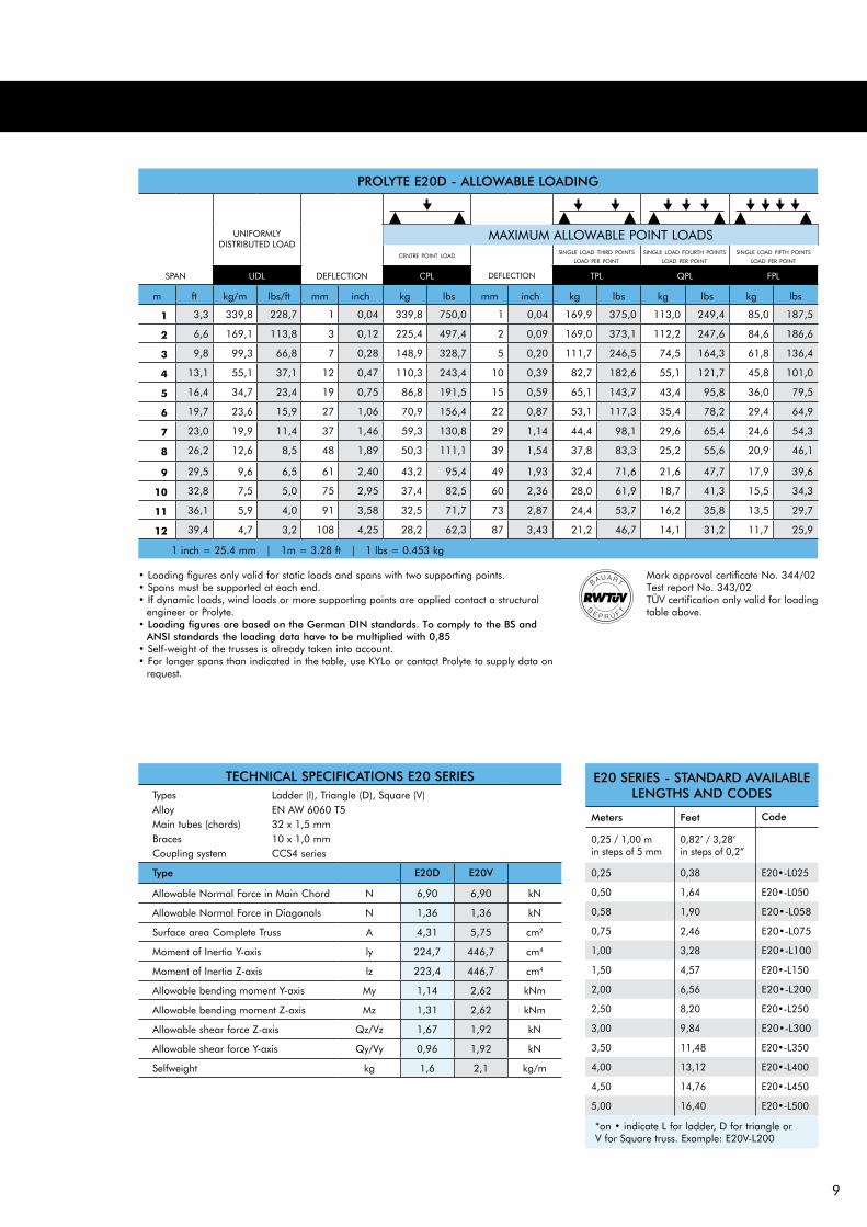
• Loading figures only valid for static loads and spans with two supporting points.• Spans must be supported at each end.• If dynamic loads, wind loads or more supporting points are applied contact a structural
engineer or Prolyte.• Loading figures are based on the German DIN standards. To comply to the BS and
ANSI standards the loading data have to be multiplied with 0,85• Self-weight of the trusses is already taken into account.• For longer spans than indicated in the table, use KYLo or contact Prolyte to supply data on
request.
TECHNICAL SPECIFICATIONS E20 SERIESTypesAlloy Main tubes (chords) Braces Coupling system
Type E20D E20V
Allowable Normal Force in Main Chord N 6,�0 6,�0 kN
Allowable Normal Force in Diagonals N 1,36 1,36 kN
Surface area Complete Truss A 4,31 5,�5 cm2
Moment of Inertia Y-axis ly 224,� 446,� cm4
Moment of Inertia Z-axis lz 223,4 446,� cm4
Allowable bending moment Y-axis My 1,14 2,62 kNm
Allowable bending moment Z-axis Mz 1,31 2,62 kNm
Allowable shear force Z-axis Qz/Vz 1,6� 1,�2 kN
Allowable shear force Y-axis Qy/Vy 0,�6 1,�2 kN
Selfweight kg 1,6 2,1 kg/m
Ladder (l), Triangle (D), Square (V)EN AW 6060 T532 x 1,5 mm10 x 1,0 mmCCS4 series
E20 SERIES - STANDARD AVAILABLE LENGTHS AND CODES
Meters Feet Code
0,25 / 1,00 m in steps of 5 mm
0,�2’ / 3,2�’ in steps of 0,2”
0,25 0,3� E20•-L025
0,50 1,64 E20•-L050
0,5� 1,�0 E20•-L05�
0,�5 2,46 E20•-L0�5
1,00 3,2� E20•-L100
1,50 4,5� E20•-L150
2,00 6,56 E20•-L200
2,50 �,20 E20•-L250
3,00 �,�4 E20•-L300
3,50 11,4� E20•-L350
4,00 13,12 E20•-L400
4,50 14,�6 E20•-L450
5,00 16,40 E20•-L500
*on • indicate L for ladder, D for triangle or V for Square truss. Example: E20V-L200
Mark approval certificate No. 344/02Test report No. 343/02TüV certification only valid for loading table above.
PROLYTE E20D - ALLOWABLE LOADING
UNIFORMLYDISTRIBUTED LOAD
centre point load
SPAN UDL DEFLECTION CPL DEFLECTION TPL QPL FPL
m ft kg/m lbs/ft mm inch kg lbs mm inch kg lbs kg lbs kg lbs
1 3,3 33�,� 22�,� 1 0,04 33�,� �50,0 1 0,04 16�,� 3�5,0 113,0 24�,4 �5,0 1��,5
2 6,6 16�,1 113,� 3 0,12 225,4 4��,4 2 0,0� 16�,0 3�3,1 112,2 24�,6 �4,6 1�6,6
3 �,� ��,3 66,� � 0,2� 14�,� 32�,� 5 0,20 111,� 246,5 �4,5 164,3 61,� 136,4
4 13,1 55,1 3�,1 12 0,4� 110,3 243,4 10 0,3� �2,� 1�2,6 55,1 121,� 45,� 101,0
5 16,4 34,� 23,4 1� 0,�5 �6,� 1�1,5 15 0,5� 65,1 143,� 43,4 �5,� 36,0 ��,5
6 1�,� 23,6 15,� 2� 1,06 �0,� 156,4 22 0,�� 53,1 11�,3 35,4 ��,2 2�,4 64,�
7 23,0 1�,� 11,4 3� 1,46 5�,3 130,� 2� 1,14 44,4 ��,1 2�,6 65,4 24,6 54,3
8 26,2 12,6 �,5 4� 1,�� 50,3 111,1 3� 1,54 3�,� �3,3 25,2 55,6 20,� 46,1
9 2�,5 �,6 6,5 61 2,40 43,2 �5,4 4� 1,�3 32,4 �1,6 21,6 4�,� 1�,� 3�,6
10 32,� �,5 5,0 �5 2,�5 3�,4 �2,5 60 2,36 2�,0 61,� 1�,� 41,3 15,5 34,3
11 36,1 5,� 4,0 �1 3,5� 32,5 �1,� �3 2,�� 24,4 53,� 16,2 35,� 13,5 2�,�
12 3�,4 4,� 3,2 10� 4,25 2�,2 62,3 �� 3,43 21,2 46,� 14,1 31,2 11,� 25,�
1 inch = 25.4 mm | 1m = 3.2� ft | 1 lbs = 0.453 kg
single load fourth points
load per point
single load fifth points
load per point
single load third points
load per point
MAXIMUM ALLOWABLE POINT LOADS

10
Mark approval certificate No. 244/02Test report No. 243/02TüV certification only valid for loading table above.
PROLYTE E20V - ALLOWABLE LOADING
UNIFORMLYDISTRIBUTED LOAD
centre point load
SPAN UDL DEFLECTION CPL DEFLECTION TPL QPL FPL
m ft kg/m lbs/ft mm inch kg lbs mm inch kg lbs kg lbs kg lbs
1 3,3 3�1,� 256,� 1 0,04 3�1,� �42,6 1 0,04 1�0,� 421,3 126,� 2�0,1 �5,4 210,6
2 6,6 1��,� 12�,� 3 0,12 3��,� �3�,� 3 0,12 1��,� 41�,0 125,� 2��,� �4,� 20�,5
3 �,� 125,� �4,� � 0,32 346,4 �64,5 6 0,24 1��,� 416,6 124,� 2�5,4 �4,4 20�,3
4 13,1 �3,� 63,2 14 0,55 25�,0 56�,3 11 0,43 1��,� 414,3 123,� 2�3,1 �3,� 20�,2
5 16,4 �4,� 50,2 22 0,�� 204,5 451,3 1� 0,6� 153,4 33�,5 102,2 225,6 �4,� 1��,3
6 1�,� 56,2 3�,� 31 1,22 16�,5 3�1,� 25 0,�� 126,4 2��,� �4,2 1�5,� 6�,� 154,3
7 23,0 40,� 2�,4 43 1,6� 142,5 314,4 34 1,34 106,� 235,� �1,2 15�,2 5�,1 130,5
8 26,2 30,� 20,6 56 2,20 122,� 2�0,� 45 1,�� �2,0 203,1 61,3 135,4 50,� 112,4
9 2�,5 23,� 16,0 �1 2,�� 10�,1 236,3 5� 2,24 �0,3 1��,2 53,5 11�,1 44,4 ��,1
10 32,� 1�,� 12,� �� 3,43 �4,4 20�,3 �0 2,�6 �0,� 156,2 4�,2 104,1 3�,2 �6,4
11 36,1 15,2 10,2 106 4,1� �3,� 1�4,� �5 3,35 62,� 13�,� 41,� �2,5 34,� �6,�
12 3�,4 12,5 �,4 126 4,�6 �4,� 165,1 101 3,�� 56,1 123,� 3�,4 �2,5 31,0 6�,5
1 inch = 25.4 mm | 1m = 3.2� ft | 1 lbs = 0.453 kg
single load fourth pointsload per point
single load fifth pointsload per point
single load third pointsload per point
MAXIMUM ALLOWABLE POINT LOADS
• Loading figures only valid for static loads and spans with two supporting points.• Spans must be supported at each end.• If dynamic loads, wind loads or more supporting points are applied contact a
structural engineer or Prolyte.• Loading figures are based on the German DIN standards. To comply to the
BS and ANSI standards the loading data have to be multiplied with 0,85• Self-weight of the trusses is already taken into account.• For longer spans than indicated in the table, use KYLo or contact Prolyte to
supply data on request.
PROLYTE E20D / E20V TRUSS

11
MULTI PURPOSE TRUSS
System CharacteristicsThe Prolyte Multi Purpose truss comprises of the X&H30 series and the H40 series. The X&H30 series are available in ladder, triangular and square types, and the H40 truss is available in triangular and square types.
The X&H30 series and the H40 series are designed as lightweight, light to medium duty truss systems that are used in the installation, rental and exhibition market. This truss is strong, compact and very versatile. The truss has a low unit weight. Assembly is foolproof, due to the continuous webbing of the diagonals.
The X and H version are distinguished by their different wall thickness. All X trusses have main chords of 2 mm.; all the H trusses have main chords of 3 mm. While their looks are almost similar, their technical specifications and loading possibilities are different. The comparatively thicker wall of the H trusses makes them less vulnerable to transport damages and extend their durability. In general X trusses are more fitted for permanent of semi-permanent installations, where H trusses are much used in the rental market or for moving grids.
System ApplicationsThe X&H30 series and the H40 series truss offer a versatility that makes them popular and much used in the exhibition as well as the rental market. The trusses are use in permanent or semi permanent installations; for example, decorative and architectural set pieces, theatre sets, shop displays, studio grids, showrooms etc.
Their strength related to the relatively small dimensions make it ideal for complex structures like displays or booths. The H trusses are primarily designed for high frequency users like rental or exhibition companies or for semi permanent installations in demanding circumstances i.e., moving lighting rigs in discotheques, scenery or touring exhibition stands.
Coupling systemThe Prolyte Multi Purpose truss comprising of the X&H30 series and the H40 series use the CCS6 conical coupling system. The CCS6 allows fast, efficient and reliable coupling of your trusses and corners.
© Prolyte Sales BV. Omke Oudeman

12
PROLYTE X30L / X30D / X30V TRUSS
X30 truss is constructed of main tubes of 51 x 2 mm and diagonals of 16 x 2 mm. Use the CCS6 coupling system.Prolyte supplies a variety of X30 truss elements that provide maximum flexibility, like standard or custom made lengths, circles and arches and several types of corners.
Prolyte can deliver custom made pieces on request.The number of recessed rings in the coupler receiver distinguishes the X and H series.
The X and H series are distinguished by the number of recessed rings in the coupler receiver.
H coupler2 rings
X coupler1 ring
Prolyte X30L side view
Prolyte X30D top view
Prolyte X30D side view
Prolyte X30V top view
Prolyte X30V side view
Prolyte X30L top view
©PROLYTE SALES BV
Photo : Metro, New ZealandProject : Four Wheel Drive vehicle
©PROLYTE SALES BV
13
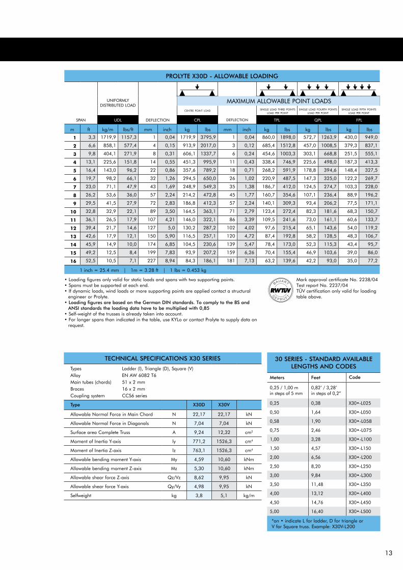
TECHNICAL SPECIFICATIONS X30 SERIES
TypesAlloy Main tubes (chords) Braces Coupling system
Type X30D X30V
Allowable Normal Force in Main Chord N 22,17 22,17 kN
Allowable Normal Force in Diagonals N 7,04 7,04 kN
Surface area Complete Truss A 9,24 12,32 cm2
Moment of Inertia Y-axis ly 771,2 1526,3 cm4
Moment of Inertia Z-axis lz 763,1 1526,3 cm4
Allowable bending moment Y-axis My 4,59 10,60 kNm
Allowable bending moment Z-axis Mz 5,30 10,60 kNm
Allowable shear force Z-axis Qz/Vz 8,62 9,95 kN
Allowable shear force Y-axis Qy/Vy 4,98 9,95 kN
Selfweight kg 3,8 5,1 kg/m
Ladder (l), Triangle (D), Square (V)EN AW 6082 T651 x 2 mm16 x 2 mmCCS6 series
30 SERIES - STANDARD AVAILAbLE LENgTHS AND CODES
Meters Feet Code
0,25 / 1,00 m in steps of 5 mm
0,82’ / 3,28’ in steps of 0,2”
0,25 0,38 X30•-L025
0,50 1,64 X30•-L050
0,58 1,90 X30•-L058
0,75 2,46 X30•-L075
1,00 3,28 X30•-L100
1,50 4,57 X30•-L150
2,00 6,56 X30•-L200
2,50 8,20 X30•-L250
3,00 9,84 X30•-L300
3,50 11,48 X30•-L350
4,00 13,12 X30•-L400
4,50 14,76 X30•-L450
5,00 16,40 X30•-L500
*on • indicate L for ladder, D for triangle or V for Square truss. Example: X30V-L200
Mark approval certificate No. 2238/04Test report No. 2237/04TüV certification only valid for loading table above.
PROLYTE X30D - ALLOWAbLE LOADINg
UNIFORMLYDISTRIBUTED LOAD
centre point load
SPAN UDL DEFLECTION CPL DEFLECTION TPL QPL FPL
m ft kg/m lbs/ft mm inch kg lbs mm inch kg lbs kg lbs kg lbs
1 3,3 1719,9 1157,3 1 0,04 1719,9 3795,9 1 0,04 860,0 1898,0 572,7 1263,9 430,0 949,0
2 6,6 858,1 577,4 4 0,15 913,9 2017,0 3 0,12 685,4 1512,8 457,0 1008,5 379,3 837,1
3 9,8 404,1 271,9 8 0,31 606,1 1337,7 6 0,24 454,6 1003,3 303,1 668,8 251,5 555,1
4 13,1 225,6 151,8 14 0,55 451,3 995,9 11 0,43 338,4 746,9 225,6 498,0 187,3 413,3
5 16,4 143,0 96,2 22 0,86 357,6 789,2 18 0,71 268,2 591,9 178,8 394,6 148,4 327,5
6 19,7 98,2 66,1 32 1,26 294,5 650,0 26 1,02 220,9 487,5 147,3 325,0 122,2 269,7
7 23,0 71,1 47,9 43 1,69 248,9 549,3 35 1,38 186,7 412,0 124,5 274,7 103,3 228,0
8 26,2 53,6 36,0 57 2,24 214,2 472,8 45 1,77 160,7 354,6 107,1 236,4 88,9 196,2
9 29,5 41,5 27,9 72 2,83 186,8 412,3 57 2,24 140,1 309,3 93,4 206,2 77,5 171,1
10 32,8 32,9 22,1 89 3,50 164,5 363,1 71 2,79 123,4 272,4 82,3 181,6 68,3 150,7
11 36,1 26,5 17,9 107 4,21 146,0 322,1 86 3,39 109,5 241,6 73,0 161,1 60,6 133,7
12 39,4 21,7 14,6 127 5,0 130,2 287,2 102 4,02 97,6 215,4 65,1 143,6 54,0 119,2
13 42,6 17,9 12,1 150 5,90 116,5 257,1 120 4,72 87,4 192,8 58,2 128,5 48,3 106,7
14 45,9 14,9 10,0 174 6,85 104,5 230,6 139 5,47 78,4 173,0 52,3 115,3 43,4 95,7
15 49,2 12,5 8,4 199 7,83 93,9 207,2 159 6,26 70,4 155,4 46,9 103,6 39,0 86,0
16 52,5 10,5 7,1 227 8,94 84,3 186,1 181 7,13 63,2 139,6 42,2 93,0 35,0 77,2
1 inch = 25.4 mm | 1m = 3.28 ft | 1 lbs = 0.453 kg
single load fourth pointsload per point
single load fifth pointsload per point
single load third pointsload per point
MAXIMUM ALLOWABLE POINT LOADS
• Loading figures only valid for static loads and spans with two supporting points.• Spans must be supported at each end.• If dynamic loads, wind loads or more supporting points are applied contact a structural
engineer or Prolyte.• Loading figures are based on the german DIN standards. To comply to the bS and
ANSI standards the loading data have to be multiplied with 0,85• Self-weight of the trusses is already taken into account.• For longer spans than indicated in the table, use KYLo or contact Prolyte to supply data on
request.

14
Mark approval certificate No. 2258/04Test report No. 2257/04TüV certification only valid for loading table above.
PROLYTE X30V - ALLOWAbLE LOADINg
UNIFORMLYDISTRIBUTED LOAD
centre point load
SPAN UDL DEFLECTION CPL DEFLECTION TPL QPL FPL
m ft kg/m lbs/ft mm inch kg lbs mm inch kg lbs kg lbs kg lbs
1 3,3 1985,3 1335,8 1 0,04 1985,3 4381,6 1 0,04 992,7 2190,8 660,9 1458,7 496,3 1095,4
2 6,6 990,1 666,2 4 0,16 1980,2 4370,3 3 0,12 990,1 2185,2 658,4 1453,0 495,1 1092,6
3 9,8 658,4 443,0 9 0,35 1405,1 3101,1 7 0,28 987,6 2179,5 655,8 1447,4 493,8 1089,8
4 13,1 492,5 331,4 17 0,67 1049,4 2316,0 13 0,51 787,0 1737,0 524,7 1158,0 435,5 961,1
5 16,4 334,0 224,7 26 1,02 834,9 1842,7 21 0,83 626,2 1382,0 417,5 921,3 346,5 764,7
6 19,7 230,4 155,0 37 1,46 691,1 1525,2 30 1,18 518,3 1143,9 345,5 762,6 286,8 633,0
7 23,0 167,9 113,0 51 2,01 587,6 1296,9 41 1,61 440,7 972,7 293,8 648,4 243,9 538,2
8 26,2 127,3 85,7 66 2,59 509,4 1124,2 53 2,08 382,0 843,2 254,7 562,1 211,4 466,6
9 29,5 99,6 67,0 84 3,31 448,0 988,7 67 2,63 336,0 741,5 224,0 494,3 185,9 410,3
10 32,8 79,7 53,6 103 4,06 398,3 879,1 83 3,27 298,8 659,3 199,2 439,6 165,3 364,8
11 36,1 65,0 43,7 125 4,92 357,3 788,5 100 3,94 267,9 591,3 178,6 394,2 148,3 327,2
12 39,4 53,8 36,2 149 5,87 322,6 712,0 119 4,69 241,9 534,0 161,3 356,0 133,9 295,5
13 42,6 45,1 30,3 175 6,89 292,9 646,4 140 5,51 219,7 484,8 146,4 323,2 121,5 268,2
14 45,9 38,1 25,7 202 7,95 267,0 589,4 162 6,38 200,3 442,0 133,5 294,7 110,8 244,6
15 49,2 32,6 21,9 233 9,17 244,3 539,2 186 7,32 183,2 404,4 122,2 269,6 101,4 223,8
16 52,5 28,0 18,8 264 10,39 224,1 494,6 212 8,35 168,1 370,9 112,0 247,3 93,0 205,3
1 inch = 25.4 mm | 1m = 3.28 ft | 1 lbs = 0.453 kg
single load fourth pointsload per point
single load fifth pointsload per point
single load third pointsload per point
MAXIMUM ALLOWABLE POINT LOADS
PROLYTE X30L / X30D / X30V TRUSS
• Loading figures only valid for static loads and spans with two supporting points.• Spans must be supported at each end.• If dynamic loads, wind loads or more supporting points are applied contact a
structural engineer or Prolyte.• Loading figures are based on the german DIN standards. To comply to the
bS and ANSI standards the loading data have to be multiplied with 0,85• Self-weight of the trusses is already taken into account.• For longer spans than indicated in the table, use KYLo or contact Prolyte to
supply data on request.

15
©PROLYTE SALES BV
©PRO
LYTE SALES BV
©PRO
LYTE SALES BV
PROLYTE X30L - ALLOWAbLE LOADINg (TOP CHORD SIDEWAYS SUPPORTED EACH METRE)
UNIFORMLYDISTRIBUTED LOAD
SPAN UDL DEFLECTION CPL DEFLECTION
m ft kg/m lbs/ft mm inch kg lbs mm inch
4 13,1 245,8 165,4 17 0,67 523,8 1156,0 13 0,51
5 16,4 166,5 112,1 26 1,02 416,3 918,9 21 0,83
6 19,7 114,7 77,2 37 1,46 344,2 759,6 30 1,18
7 23,0 83,5 56,2 51 2,01 292,2 645,0 41 1,61
8 26,2 63,2 42,5 66 2,60 252,9 558,1 53 2,09
9 29,5 49,3 33,2 84 3,31 222,0 489,9 67 2,64
10 32,8 39,0 25,6 100 3,94 196,9 434,6 83 3,27
11 36,1 27,8 18,7 110 4,33 176,2 388,8 100 3,94
12 39,4 20,7 13,9 120 4,72 158,6 350,0 119 4,69
1 inch = 25.4 mm | 1m = 3.28 ft | 1 lbs = 0.453 kg
PROLYTE X30L - ALLOWAbLE LOADINg (TOP CHORD SIDEWAYS SUPPORTED EVERY 2 METRES)
UNIFORMLYDISTRIBUTED LOAD
SPAN UDL DEFLECTION CPL DEFLECTION
m ft kg/m lbs/ft mm inch kg lbs mm inch
4 13,1 82,5 55,5 5 0,20 165,0 364,2 4 0,16
5 16,4 51,7 34,8 8 0,32 129,3 285,4 7 0,28
6 19,7 35,0 23,6 12 0,47 105,0 231,7 10 0,39
7 23,0 24,9 16,8 16 0,63 87,2 192,5 13 0,51
8 26,2 18,4 12,4 21 0,83 73,5 162,2 17 0,67
9 29,5 13,9 9,3 27 1,06 62,5 137,9 22 0,87
10 32,8 10,7 7,2 33 1,30 53,4 117,9 27 1,06
11 36,1 8,3 5,6 40 1,57 45,7 100,8 32 1,26
12 39,4 6,5 4,4 48 1,89 39,0 86,1 38 1,50
1 inch = 25.4 mm | 1m = 3.28 ft | 1 lbs = 0.453 kg
Spans must be supported at each end. Loads must be suspended from bottom chord only.
Spans must be supported at each end. Loads must be suspended from bottom chord only.
Spans must be supported at each end. Loads must be suspended from bottom chord only.
PROLYTE X30L - ALLOWAbLE LOADINg (SPAN SUPPORTED ON TOP CHORD)
UNIFORMLYDISTRIBUTED LOAD
SPAN UDL DEFLECTION CPL DEFLECTION
m ft kg/m lbs/ft mm inch kg lbs mm inch
1 3,3 992,2 667,6 0 0 992,2 2189,8 0 0
2 6,6 339,0 228,1 1 0,04 339,0 748,2 1 0,04
3 9,8 114,0 76,7 2 0,08 171,0 377,4 2 0,08
4 13,1 44,0 29,6 3 0,12 88,0 194,2 2 0,08
5 16,4 20,0 13,5 3 0,12 50,0 110,4 2 0,08
6 19,7 9,0 6,1 3 0,12 26,0 57,4 2 0,08
1 inch = 25.4 mm | 1m = 3.28 ft | 1 lbs = 0.453 kg

16
PROLYTE H30L /H30D / H30V TRUSS
H30 truss is constructed of main tubes of 48,3 x 3 mm and diagonals of 16 x 2 mm. Use the CCS6 coupling system.Prolyte supplies a variety of H30 truss elements that provide maximum flexibility, like standard or custom made lengths, circles and arches and several types of corners.
Prolyte can deliver custom made pieces on request.
The number of recessed rings in the coupler receiver distinguishes the X and H series.
Prolyte H30L top view
Prolyte H30D top view
Prolyte H30D side view
Prolyte H30V top view
Prolyte H30V side view
Prolyte H30L side view
©PROLYTE SALES BV
Photo : Creativ-Design, Germany
17
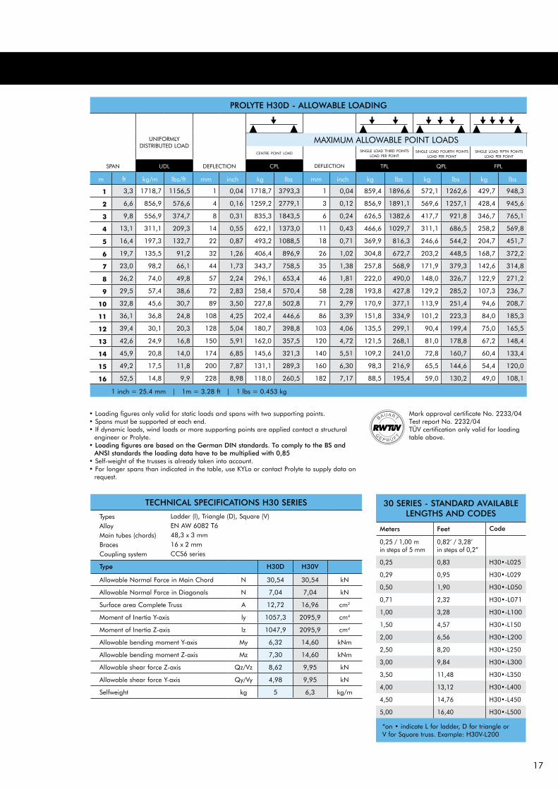
TECHNICAL SPECIFICATIONS H30 SERIES
TypesAlloy Main tubes (chords) Braces Coupling system
Type H30D H30V
Allowable Normal Force in Main Chord N 30,54 30,54 kN
Allowable Normal Force in Diagonals N 7,04 7,04 kN
Surface area Complete Truss A 12,72 16,96 cm2
Moment of Inertia Y-axis ly 1057,3 2095,9 cm4
Moment of Inertia Z-axis lz 1047,9 2095,9 cm4
Allowable bending moment Y-axis My 6,32 14,60 kNm
Allowable bending moment Z-axis Mz 7,30 14,60 kNm
Allowable shear force Z-axis Qz/Vz 8,62 9,95 kN
Allowable shear force Y-axis Qy/Vy 4,98 9,95 kN
Selfweight kg 5 6,3 kg/m
Ladder (l), Triangle (D), Square (V)EN AW 6082 T648,3 x 3 mm16 x 2 mmCCS6 series
30 SERIES - STANDARD AVAILAbLE LENgTHS AND CODES
Meters Feet Code
0,25 / 1,00 m in steps of 5 mm
0,82’ / 3,28’ in steps of 0,2”
0,25 0,83 H30•-L025
0,29 0,95 H30•-L029
0,50 1,90 H30•-L050
0,71 2,32 H30•-L071
1,00 3,28 H30•-L100
1,50 4,57 H30•-L150
2,00 6,56 H30•-L200
2,50 8,20 H30•-L250
3,00 9,84 H30•-L300
3,50 11,48 H30•-L350
4,00 13,12 H30•-L400
4,50 14,76 H30•-L450
5,00 16,40 H30•-L500
*on • indicate L for ladder, D for triangle or V for Square truss. Example: H30V-L200
Mark approval certificate No. 2233/04Test report No. 2232/04TüV certification only valid for loading table above.
PROLYTE H30D - ALLOWAbLE LOADINg
UNIFORMLYDISTRIBUTED LOAD
centre point load
SPAN UDL DEFLECTION CPL DEFLECTION TPL QPL FPL
m ft kg/m lbs/ft mm inch kg lbs mm inch kg lbs kg lbs kg lbs
1 3,3 1718,7 1156,5 1 0,04 1718,7 3793,3 1 0,04 859,4 1896,6 572,1 1262,6 429,7 948,3
2 6,6 856,9 576,6 4 0,16 1259,2 2779,1 3 0,12 856,9 1891,1 569,6 1257,1 428,4 945,6
3 9,8 556,9 374,7 8 0,31 835,3 1843,5 6 0,24 626,5 1382,6 417,7 921,8 346,7 765,1
4 13,1 311,1 209,3 14 0,55 622,1 1373,0 11 0,43 466,6 1029,7 311,1 686,5 258,2 569,8
5 16,4 197,3 132,7 22 0,87 493,2 1088,5 18 0,71 369,9 816,3 246,6 544,2 204,7 451,7
6 19,7 135,5 91,2 32 1,26 406,4 896,9 26 1,02 304,8 672,7 203,2 448,5 168,7 372,2
7 23,0 98,2 66,1 44 1,73 343,7 758,5 35 1,38 257,8 568,9 171,9 379,3 142,6 314,8
8 26,2 74,0 49,8 57 2,24 296,1 653,4 46 1,81 222,0 490,0 148,0 326,7 122,9 271,2
9 29,5 57,4 38,6 72 2,83 258,4 570,4 58 2,28 193,8 427,8 129,2 285,2 107,3 236,7
10 32,8 45,6 30,7 89 3,50 227,8 502,8 71 2,79 170,9 377,1 113,9 251,4 94,6 208,7
11 36,1 36,8 24,8 108 4,25 202,4 446,6 86 3,39 151,8 334,9 101,2 223,3 84,0 185,3
12 39,4 30,1 20,3 128 5,04 180,7 398,8 103 4,06 135,5 299,1 90,4 199,4 75,0 165,5
13 42,6 24,9 16,8 150 5,91 162,0 357,5 120 4,72 121,5 268,1 81,0 178,8 67,2 148,4
14 45,9 20,8 14,0 174 6,85 145,6 321,3 140 5,51 109,2 241,0 72,8 160,7 60,4 133,4
15 49,2 17,5 11,8 200 7,87 131,1 289,3 160 6,30 98,3 216,9 65,5 144,6 54,4 120,0
16 52,5 14,8 9,9 228 8,98 118,0 260,5 182 7,17 88,5 195,4 59,0 130,2 49,0 108,1
1 inch = 25.4 mm | 1m = 3.28 ft | 1 lbs = 0.453 kg
single load fourth pointsload per point
single load fifth pointsload per point
single load third pointsload per point
MAXIMUM ALLOWABLE POINT LOADS
• Loading figures only valid for static loads and spans with two supporting points.• Spans must be supported at each end.• If dynamic loads, wind loads or more supporting points are applied contact a structural
engineer or Prolyte.• Loading figures are based on the german DIN standards. To comply to the bS and
ANSI standards the loading data have to be multiplied with 0,85• Self-weight of the trusses is already taken into account.• For longer spans than indicated in the table, use KYLo or contact Prolyte to supply data on
request.
18
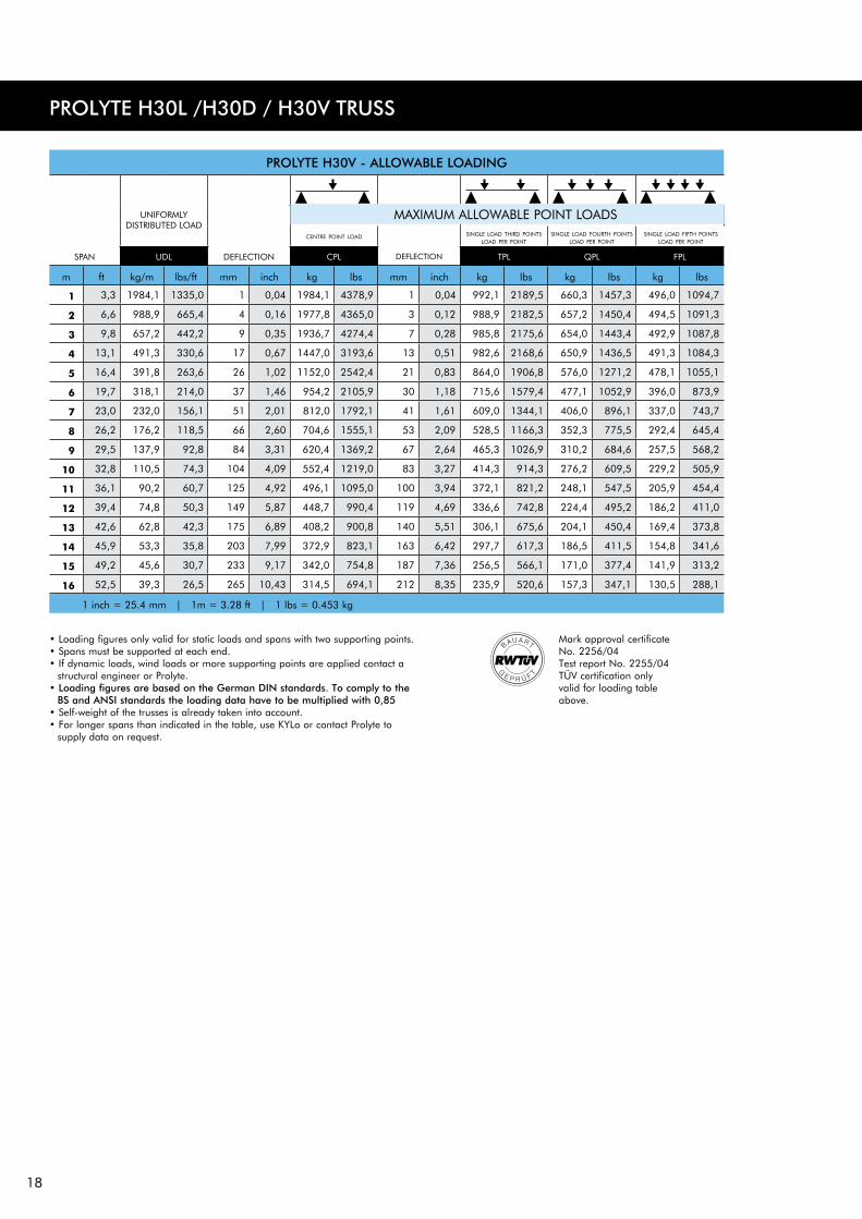
PROLYTE H30V - ALLOWAbLE LOADINg
UNIFORMLYDISTRIBUTED LOAD
centre point load
SPAN UDL DEFLECTION CPL DEFLECTION TPL QPL FPL
m ft kg/m lbs/ft mm inch kg lbs mm inch kg lbs kg lbs kg lbs
1 3,3 1984,1 1335,0 1 0,04 1984,1 4378,9 1 0,04 992,1 2189,5 660,3 1457,3 496,0 1094,7
2 6,6 988,9 665,4 4 0,16 1977,8 4365,0 3 0,12 988,9 2182,5 657,2 1450,4 494,5 1091,3
3 9,8 657,2 442,2 9 0,35 1936,7 4274,4 7 0,28 985,8 2175,6 654,0 1443,4 492,9 1087,8
4 13,1 491,3 330,6 17 0,67 1447,0 3193,6 13 0,51 982,6 2168,6 650,9 1436,5 491,3 1084,3
5 16,4 391,8 263,6 26 1,02 1152,0 2542,4 21 0,83 864,0 1906,8 576,0 1271,2 478,1 1055,1
6 19,7 318,1 214,0 37 1,46 954,2 2105,9 30 1,18 715,6 1579,4 477,1 1052,9 396,0 873,9
7 23,0 232,0 156,1 51 2,01 812,0 1792,1 41 1,61 609,0 1344,1 406,0 896,1 337,0 743,7
8 26,2 176,2 118,5 66 2,60 704,6 1555,1 53 2,09 528,5 1166,3 352,3 775,5 292,4 645,4
9 29,5 137,9 92,8 84 3,31 620,4 1369,2 67 2,64 465,3 1026,9 310,2 684,6 257,5 568,2
10 32,8 110,5 74,3 104 4,09 552,4 1219,0 83 3,27 414,3 914,3 276,2 609,5 229,2 505,9
11 36,1 90,2 60,7 125 4,92 496,1 1095,0 100 3,94 372,1 821,2 248,1 547,5 205,9 454,4
12 39,4 74,8 50,3 149 5,87 448,7 990,4 119 4,69 336,6 742,8 224,4 495,2 186,2 411,0
13 42,6 62,8 42,3 175 6,89 408,2 900,8 140 5,51 306,1 675,6 204,1 450,4 169,4 373,8
14 45,9 53,3 35,8 203 7,99 372,9 823,1 163 6,42 297,7 617,3 186,5 411,5 154,8 341,6
15 49,2 45,6 30,7 233 9,17 342,0 754,8 187 7,36 256,5 566,1 171,0 377,4 141,9 313,2
16 52,5 39,3 26,5 265 10,43 314,5 694,1 212 8,35 235,9 520,6 157,3 347,1 130,5 288,1
1 inch = 25.4 mm | 1m = 3.28 ft | 1 lbs = 0.453 kg
single load fourth points load per point
single load fifth pointsload per point
single load third pointsload per point
MAXIMUM ALLOWABLE POINT LOADS
PROLYTE H30L /H30D / H30V TRUSS
Mark approval certificate No. 2256/04Test report No. 2255/04TüV certification only valid for loading table above.
• Loading figures only valid for static loads and spans with two supporting points.• Spans must be supported at each end.• If dynamic loads, wind loads or more supporting points are applied contact a
structural engineer or Prolyte.• Loading figures are based on the german DIN standards. To comply to the
bS and ANSI standards the loading data have to be multiplied with 0,85• Self-weight of the trusses is already taken into account.• For longer spans than indicated in the table, use KYLo or contact Prolyte to
supply data on request.
19
©PROLYTE SALES BV
©PRO
LYTE SALES BV
©PRO
LYTE SALES BV
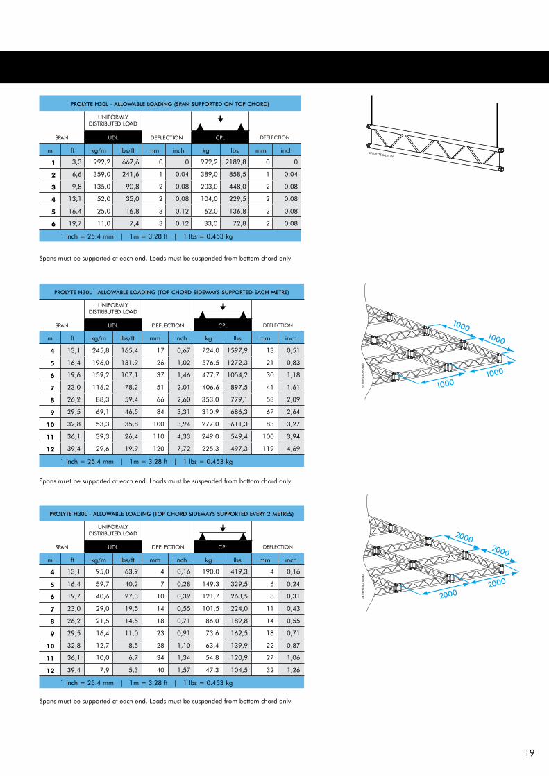
PROLYTE H30L - ALLOWAbLE LOADINg (TOP CHORD SIDEWAYS SUPPORTED EACH METRE)
UNIFORMLYDISTRIBUTED LOAD
SPAN UDL DEFLECTION CPL DEFLECTION
m ft kg/m lbs/ft mm inch kg lbs mm inch
4 13,1 245,8 165,4 17 0,67 724,0 1597,9 13 0,51
5 16,4 196,0 131,9 26 1,02 576,5 1272,3 21 0,83
6 19,6 159,2 107,1 37 1,46 477,7 1054,2 30 1,18
7 23,0 116,2 78,2 51 2,01 406,6 897,5 41 1,61
8 26,2 88,3 59,4 66 2,60 353,0 779,1 53 2,09
9 29,5 69,1 46,5 84 3,31 310,9 686,3 67 2,64
10 32,8 53,3 35,8 100 3,94 277,0 611,3 83 3,27
11 36,1 39,3 26,4 110 4,33 249,0 549,4 100 3,94
12 39,4 29,6 19,9 120 7,72 225,3 497,3 119 4,69
1 inch = 25.4 mm | 1m = 3.28 ft | 1 lbs = 0.453 kg
PROLYTE H30L - ALLOWAbLE LOADINg (TOP CHORD SIDEWAYS SUPPORTED EVERY 2 METRES)
UNIFORMLYDISTRIBUTED LOAD
SPAN UDL DEFLECTION CPL DEFLECTION
m ft kg/m lbs/ft mm inch kg lbs mm inch
4 13,1 95,0 63,9 4 0,16 190,0 419,3 4 0,16
5 16,4 59,7 40,2 7 0,28 149,3 329,5 6 0,24
6 19,7 40,6 27,3 10 0,39 121,7 268,5 8 0,31
7 23,0 29,0 19,5 14 0,55 101,5 224,0 11 0,43
8 26,2 21,5 14,5 18 0,71 86,0 189,8 14 0,55
9 29,5 16,4 11,0 23 0,91 73,6 162,5 18 0,71
10 32,8 12,7 8,5 28 1,10 63,4 139,9 22 0,87
11 36,1 10,0 6,7 34 1,34 54,8 120,9 27 1,06
12 39,4 7,9 5,3 40 1,57 47,3 104,5 32 1,26
1 inch = 25.4 mm | 1m = 3.28 ft | 1 lbs = 0.453 kg
Spans must be supported at each end. Loads must be suspended from bottom chord only.
Spans must be supported at each end. Loads must be suspended from bottom chord only.
Spans must be supported at each end. Loads must be suspended from bottom chord only.
PROLYTE H30L - ALLOWAbLE LOADINg (SPAN SUPPORTED ON TOP CHORD)
UNIFORMLYDISTRIBUTED LOAD
SPAN UDL DEFLECTION CPL DEFLECTION
m ft kg/m lbs/ft mm inch kg lbs mm inch
1 3,3 992,2 667,6 0 0 992,2 2189,8 0 0
2 6,6 359,0 241,6 1 0,04 389,0 858,5 1 0,04
3 9,8 135,0 90,8 2 0,08 203,0 448,0 2 0,08
4 13,1 52,0 35,0 2 0,08 104,0 229,5 2 0,08
5 16,4 25,0 16,8 3 0,12 62,0 136,8 2 0,08
6 19,7 11,0 7,4 3 0,12 33,0 72,8 2 0,08
1 inch = 25.4 mm | 1m = 3.28 ft | 1 lbs = 0.453 kg

20
PROLYTE H40D / H40V TRUSS
H40 truss is constructed of main tubes of 48,3 x 3 mm and diagonals of 20 x 2 mm. Use the CCS6 coupling system. Prolyte supplies a variety of H40 truss elements that provide
maximum flexibility, like standard or custom made lengths, circles and arches and several types of corners. Prolyte can deliver custom made pieces on request.
Prolyte H40D top view
Prolyte H40D side view Prolyte H40V side view
Prolyte H40V top view
Prolyte H40L top view
Prolyte H40L side view
©PROLYTE SALES BV
Photo : Prolyte Sales BVProject : Media Centrale, Groningen, H40 truss
21
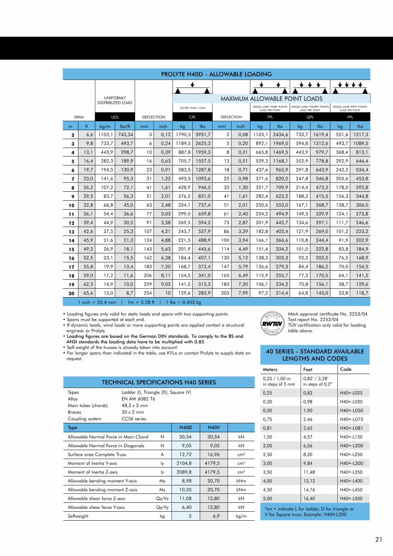
TECHNICAL SPECIFICATIONS H40 SERIES
TypesAlloy Main tubes (chords) Braces Coupling system
Type H40D H40V
Allowable Normal Force in Main Chord N 30,54 30,54 kN
Allowable Normal Force in Diagonals N 9,05 9,05 kN
Surface area Complete Truss A 12,72 16,96 cm2
Moment of Inertia Y-axis ly 2104,8 4179,5 cm4
Moment of Inertia Z-axis lz 2089,8 4179,5 cm4
Allowable bending moment Y-axis My 8,98 20,70 kNm
Allowable bending moment Z-axis Mz 10,35 20,70 kNm
Allowable shear force Z-axis Qz/Vz 11,08 12,80 kN
Allowable shear force Y-axis Qy/Vy 6,40 12,80 kN
Selfweight kg 5 6,9 kg/m
Ladder (l), Triangle (D), Square (V)EN AW 6082 T648,3 x 3 mm20 x 2 mmCCS6 series
40 SERIES - STANDARD AVAILAbLE LENgTHS AND CODES
Meters Feet Code
0,25 / 1,00 m in steps of 5 mm
0,82’ / 3,28’ in steps of 0,2”
0,25 0,83 H40•-L025
0,30 0,98 H40•-L030
0,50 1,90 H40•-L050
0,75 2,46 H40•-L075
0,81 2,65 H40•-L081
1,50 4,57 H40•-L150
2,00 6,56 H40•-L200
2,50 8,20 H40•-L250
3,00 9,84 H40•-L300
3,50 11,48 H40•-L350
4,00 13,12 H40•-L400
4,50 14,76 H40•-L450
5,00 16,40 H40•-L500
*on • indicate L for ladder, D for triangle or V for Square truss. Example: H40V-L200
PROLYTE H40D - ALLOWAbLE LOADINg
UNIFORMLYDISTRIBUTED LOAD
centre point load
SPAN UDL DEFLECTION CPL DEFLECTION TPL QPL FPL
m ft kg/m lbs/ft mm inch kg lbs mm inch kg lbs kg lbs kg lbs
2 6,6 1103,1 742,34 3 0,12 1790,5 3951,7 2 0,08 1103,1 2434,6 733,7 1619,4 551,6 1217,3
3 9,8 733,7 493,7 6 0,24 1189,5 2625,3 5 0,20 892,1 1969,0 594,8 1312,6 493,7 1089,5
4 13,1 443,9 298,7 10 0,39 887,8 1959,3 8 0,31 665,8 1469,5 443,9 979,7 368,4 813,1
5 16,4 282,3 189,9 16 0,63 705,7 1557,5 13 0,51 529,3 1168,1 352,9 778,8 292,9 646,4
6 19,7 194,5 130,9 23 0,91 583,5 1287,8 18 0,71 437,6 965,9 291,8 643,9 242,2 534,4
7 23,0 141,6 95,3 31 1,22 495,5 1093,6 25 0,98 371,6 820,2 247,8 546,8 205,6 453,8
8 26,2 107,2 72,1 41 1,61 428,9 946,5 33 1,30 321,7 709,9 214,4 473,3 178,0 392,8
9 29,5 83,7 56,3 51 2,01 376,5 831,0 41 1,61 282,4 623,2 188,3 415,5 156,3 344,8
10 32,8 66,8 45,0 63 2,48 334,1 737,4 51 2,01 250,6 553,0 167,1 368,7 138,7 306,0
11 36,1 54,4 36,6 77 3,03 299,0 659,8 61 2,40 224,2 494,9 149,5 329,9 124,1 273,8
12 39,4 44,9 30,2 91 3,58 269,3 594,2 73 2,87 201,9 445,7 134,6 297,1 111,7 246,6
13 42,6 37,5 25,2 107 4,21 243,7 537,9 86 3,39 182,8 403,4 121,9 269,0 101,2 223,2
14 45,9 31,6 21,3 124 4,88 221,5 488,9 100 3,94 166,1 366,6 110,8 244,4 91,9 202,9
15 49,2 26,9 18,1 143 5,63 201,9 445,6 114 4,49 151,4 334,2 101,0 222,8 83,8 184,9
16 52,5 23,1 15,5 162 6,38 184,4 407,1 130 5,12 138,3 305,3 92,2 203,5 76,5 168,9
17 55,8 19,9 13,4 183 7,20 168,7 372,4 147 5,79 126,6 279,3 84,4 186,2 70,0 154,5
18 59,0 17,2 11,6 206 8,11 154,5 341,0 165 6,49 115,9 255,7 77,3 170,5 64,1 141,5
19 62,3 14,9 10,0 229 9,02 141,5 312,3 183 7,20 106,1 234,2 70,8 156,1 58,7 129,6
20 65,6 13,0 8,7 254 10 129,6 285,9 203 7,99 97,2 214,4 64,8 143,0 53,8 118,7
1 inch = 25.4 mm | 1m = 3.28 ft | 1 lbs = 0.453 kg
single load fourth pointsload per point
single load fifth pointsload per point
single load third pointsload per point
MAXIMUM ALLOWABLE POINT LOADS
Mark approval certificate No. 2253/04Test report No. 2252/04TüV certification only valid for loading table above.
• Loading figures only valid for static loads and spans with two supporting points.• Spans must be supported at each end.• If dynamic loads, wind loads or more supporting points are applied contact a structural
engineer or Prolyte.• Loading figures are based on the german DIN standards. To comply to the bS and
ANSI standards the loading data have to be multiplied with 0,85• Self-weight of the trusses is already taken into account.• For longer spans than indicated in the table, use KYLo or contact Prolyte to supply data on
request.
22
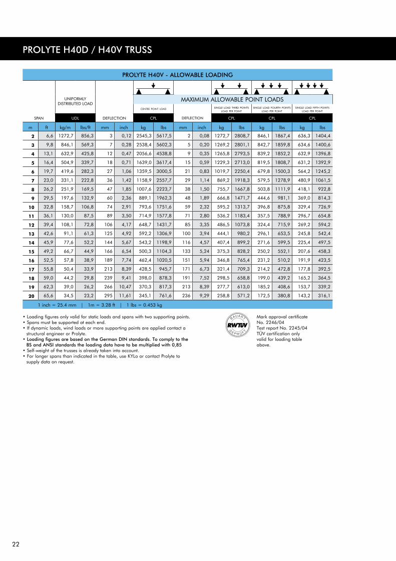
PROLYTE H40V - ALLOWAbLE LOADINg
UNIFORMLYDISTRIBUTED LOAD
centre point load
SPAN UDL DEFLECTION CPL DEFLECTION CPL CPL CPL
m ft kg/m lbs/ft mm inch kg lbs mm inch kg lbs kg lbs kg lbs
2 6,6 1272,7 856,3 3 0,12 2545,3 5617,5 2 0,08 1272,7 2808,7 846,1 1867,4 636,3 1404,4
3 9,8 846,1 569,3 7 0,28 2538,4 5602,3 5 0,20 1269,2 2801,1 842,7 1859,8 634,6 1400,6
4 13,1 632,9 425,8 12 0,47 2056,6 4538,8 9 0,35 1265,8 2793,5 839,2 1852,2 632,9 1396,8
5 16,4 504,9 339,7 18 0,71 1639,0 3617,4 15 0,59 1229,3 2713,0 819,5 1808,7 631,2 1392,9
6 19,7 419,6 282,3 27 1,06 1359,5 3000,5 21 0,83 1019,7 2250,4 679,8 1500,3 564,2 1245,2
7 23,0 331,1 222,8 36 1,42 1158,9 2557,7 29 1,14 869,2 1918,3 579,5 1278,9 480,9 1061,5
8 26,2 251,9 169,5 47 1,85 1007,6 2223,7 38 1,50 755,7 1667,8 503,8 1111,9 418,1 922,8
9 29,5 197,6 132,9 60 2,36 889,1 1962,3 48 1,89 666,8 1471,7 444,6 981,1 369,0 814,3
10 32,8 158,7 106,8 74 2,91 793,6 1751,6 59 2,32 595,2 1313,7 396,8 875,8 329,4 726,9
11 36,1 130,0 87,5 89 3,50 714,9 1577,8 71 2,80 536,2 1183,4 357,5 788,9 296,7 654,8
12 39,4 108,1 72,8 106 4,17 648,7 1431,7 85 3,35 486,5 1073,8 324,4 715,9 269,2 594,2
13 42,6 91,1 61,3 125 4,92 592,2 1306,9 100 3,94 444,1 980,2 296,1 653,5 245,8 542,4
14 45,9 77,6 52,2 144 5,67 543,2 1198,9 116 4,57 407,4 899,2 271,6 599,5 225,4 497,5
15 49,2 66,7 44,9 166 6,54 500,3 1104,3 133 5,24 375,3 828,2 250,2 552,1 207,6 458,3
16 52,5 57,8 38,9 189 7,74 462,4 1020,5 151 5,94 346,8 765,4 231,2 510,2 191,9 423,5
17 55,8 50,4 33,9 213 8,39 428,5 945,7 171 6,73 321,4 709,3 214,2 472,8 177,8 392,5
18 59,0 44,2 29,8 239 9,41 398,0 878,3 191 7,52 298,5 658,8 199,0 439,2 165,2 364,5
19 62,3 39,0 26,2 266 10,47 370,3 817,3 213 8,39 277,7 613,0 185,2 408,6 153,7 339,2
20 65,6 34,5 23,2 295 11,61 345,1 761,6 236 9,29 258,8 571,2 172,5 380,8 143,2 316,1
1 inch = 25.4 mm | 1m = 3.28 ft | 1 lbs = 0.453 kg
single load fourth pointsload per point
single load fifth pointsload per point
single load third pointsload per point
MAXIMUM ALLOWABLE POINT LOADS
PROLYTE H40D / H40V TRUSS
Mark approval certificate No. 2246/04Test report No. 2245/04TüV certification only valid for loading table above.
• Loading figures only valid for static loads and spans with two supporting points.• Spans must be supported at each end.• If dynamic loads, wind loads or more supporting points are applied contact a
structural engineer or Prolyte.• Loading figures are based on the german DIN standards. To comply to the
bS and ANSI standards the loading data have to be multiplied with 0,85• Self-weight of the trusses is already taken into account.• For longer spans than indicated in the table, use KYLo or contact Prolyte to
supply data on request.
23
©PROLYTE SALES BV
©PRO
LYTE SALES BV
©PRO
LYTE SALES BV
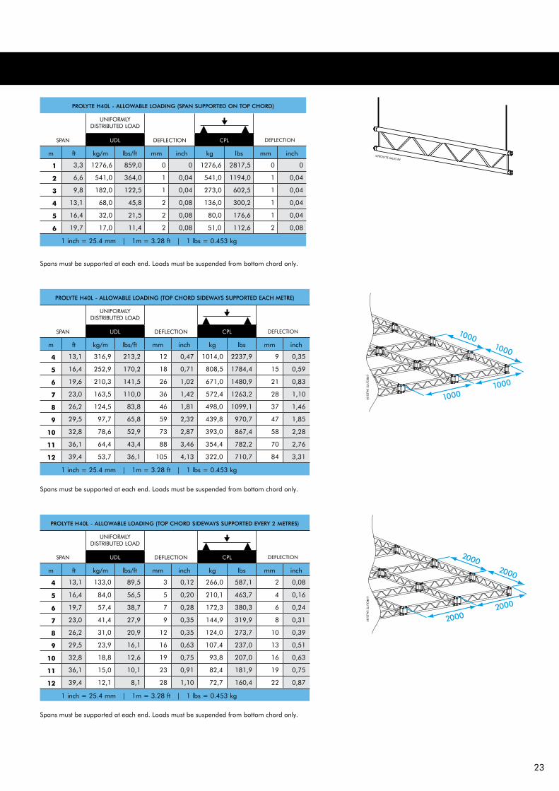
PROLYTE H40L - ALLOWAbLE LOADINg (TOP CHORD SIDEWAYS SUPPORTED EACH METRE)
UNIFORMLYDISTRIBUTED LOAD
SPAN UDL DEFLECTION CPL DEFLECTION
m ft kg/m lbs/ft mm inch kg lbs mm inch
4 13,1 316,9 213,2 12 0,47 1014,0 2237,9 9 0,35
5 16,4 252,9 170,2 18 0,71 808,5 1784,4 15 0,59
6 19,6 210,3 141,5 26 1,02 671,0 1480,9 21 0,83
7 23,0 163,5 110,0 36 1,42 572,4 1263,2 28 1,10
8 26,2 124,5 83,8 46 1,81 498,0 1099,1 37 1,46
9 29,5 97,7 65,8 59 2,32 439,8 970,7 47 1,85
10 32,8 78,6 52,9 73 2,87 393,0 867,4 58 2,28
11 36,1 64,4 43,4 88 3,46 354,4 782,2 70 2,76
12 39,4 53,7 36,1 105 4,13 322,0 710,7 84 3,31
1 inch = 25.4 mm | 1m = 3.28 ft | 1 lbs = 0.453 kg
PROLYTE H40L - ALLOWAbLE LOADINg (TOP CHORD SIDEWAYS SUPPORTED EVERY 2 METRES)
UNIFORMLYDISTRIBUTED LOAD
SPAN UDL DEFLECTION CPL DEFLECTION
m ft kg/m lbs/ft mm inch kg lbs mm inch
4 13,1 133,0 89,5 3 0,12 266,0 587,1 2 0,08
5 16,4 84,0 56,5 5 0,20 210,1 463,7 4 0,16
6 19,7 57,4 38,7 7 0,28 172,3 380,3 6 0,24
7 23,0 41,4 27,9 9 0,35 144,9 319,9 8 0,31
8 26,2 31,0 20,9 12 0,35 124,0 273,7 10 0,39
9 29,5 23,9 16,1 16 0,63 107,4 237,0 13 0,51
10 32,8 18,8 12,6 19 0,75 93,8 207,0 16 0,63
11 36,1 15,0 10,1 23 0,91 82,4 181,9 19 0,75
12 39,4 12,1 8,1 28 1,10 72,7 160,4 22 0,87
1 inch = 25.4 mm | 1m = 3.28 ft | 1 lbs = 0.453 kg
Spans must be supported at each end. Loads must be suspended from bottom chord only.
Spans must be supported at each end. Loads must be suspended from bottom chord only.
Spans must be supported at each end. Loads must be suspended from bottom chord only.
PROLYTE H40L - ALLOWAbLE LOADINg (SPAN SUPPORTED ON TOP CHORD)
UNIFORMLYDISTRIBUTED LOAD
SPAN UDL DEFLECTION CPL DEFLECTION
m ft kg/m lbs/ft mm inch kg lbs mm inch
1 3,3 1276,6 859,0 0 0 1276,6 2817,5 0 0
2 6,6 541,0 364,0 1 0,04 541,0 1194,0 1 0,04
3 9,8 182,0 122,5 1 0,04 273,0 602,5 1 0,04
4 13,1 68,0 45,8 2 0,08 136,0 300,2 1 0,04
5 16,4 32,0 21,5 2 0,08 80,0 176,6 1 0,04
6 19,7 17,0 11,4 2 0,08 51,0 112,6 2 0,08
1 inch = 25.4 mm | 1m = 3.28 ft | 1 lbs = 0.453 kg
25
HEAVY DUTY TRUSS
Photo: Italstage, Italy
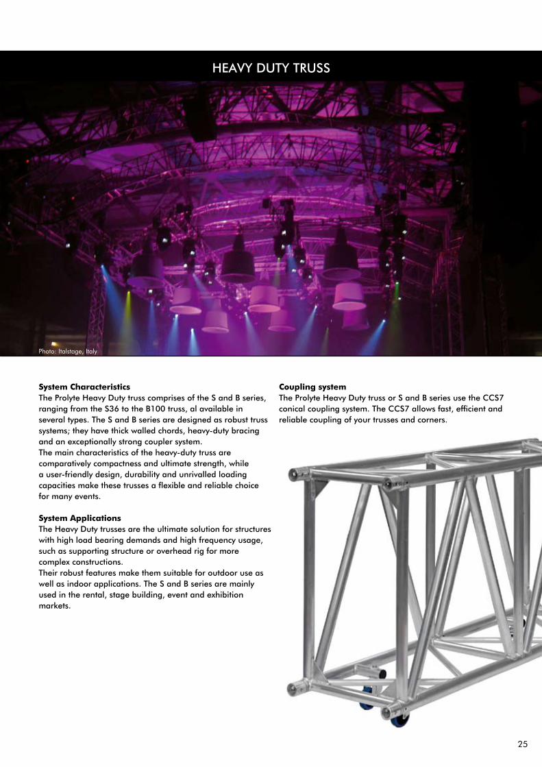
System CharacteristicsThe Prolyte Heavy Duty truss comprises of the S and B series, ranging from the S36 to the B100 truss, al available in several types. The S and B series are designed as robust truss systems; they have thick walled chords, heavy-duty bracing and an exceptionally strong coupler system. The main characteristics of the heavy-duty truss are comparatively compactness and ultimate strength, while a user-friendly design, durability and unrivalled loading capacities make these trusses a flexible and reliable choice for many events. System ApplicationsThe Heavy Duty trusses are the ultimate solution for structures with high load bearing demands and high frequency usage, such as supporting structure or overhead rig for more complex constructions. Their robust features make them suitable for outdoor use as well as indoor applications. The S and B series are mainly used in the rental, stage building, event and exhibition markets.
Coupling system The Prolyte Heavy Duty truss or S and B series use the CCS7 conical coupling system. The CCS7 allows fast, efficient and reliable coupling of your trusses and corners.

26
S36 truss is constructed of main tubes of 50 x 4 mm and diagonals of 25 x 3 mm. Use the CCS7 coupling system. Prolyte supplies a variety of S36 truss elements that provide maximum flexibility, like standard or custom made lengths, circles and arches and several types of corners. Prolyte can deliver custom made pieces on request.
The S36V has a 4-sided diagonal webbing and can therefore absorb vertical as well as horizontal loads. The S36R can only absorb vertical loading. Thanks to the clever spigot pin orientation in the couplers, assembly of the truss is foolproof.
Prolyte S36R top view
Prolyte S36R side view
Prolyte S36V top view
Prolyte S36V side view
PROLYTE S36R / S36V TRUSS
©PROLYTE SALES BV
Photo : Prolyte Sales BV Project : Amusement park, Germany

27
TECHNICAL SPECIFICATIONS S36 SERIES
TypesAlloy Main tubes (chords) Braces Coupling system
Type S36R S36V
Allowable Normal Force in Main Chord N 41,62 41,62 kN
Allowable Normal Force in Diagonals N 16,59 16,59 kN
Surface area Complete Truss A 23,12 23,12 cm2
Moment of Inertia Y-axis ly 4445,1 4445,1 cm4
Moment of Inertia Z-axis lz 1250,0 4445,1 cm4
Allowable bending moment Y-axis My 24,89 24,89 kNm
Allowable bending moment Z-axis Mz - 24,89 kNm
Allowable shear force Z-axis Qz/Vz 23,46 23,46 kN
Allowable shear force Y-axis Qy/Vy - 23,46 kN
Selfweight kg 10,5 12 kg/m
Rectangle (R), Square (V)EN AW 6082 T650 x 4 mm25 x 3 mmCCS7 series
S36 SERIES - STANDARD AVAILABLE LENgTHS AND CODES
Meters Feet Code
0,25 / 1,00 m in steps of 5 mm
0,82’ / 3,28’ in steps of 0,2”
0,50 1,64 S36•-L050
0,60 1,97 S36•-L060
0,80 2,62 S36•-L080
1,00 3,28 S36•-L100
1,20 3,94 S36•-L120
1,50 4,92 S36•-L150
1,60 5,25 S36•-L160
2,00 6,56 S36•-L200
2,40 7,87 S36•-L240
2,50 8,20 S36•-L250
3,00 9,84 S36•-L300
3,20 10,50 S36•-L320
3,50 11,48 S36•-L350
4,00 13,12 S36•-L400
*on • indicate R for rectangle, V for Square truss. Example: S36V-L200
PROLYTE S36R - ALLOWABLE LOADINg
UNIFORMLYDISTRIBUTED LOAD
centre point load
SPAN UDL DEFLECTION CPL DEFLECTION TPL QPL FPL
m ft kg/m lbs/ft mm inch kg lbs mm inch kg lbs kg lbs kg lbs
2 6,6 2335,3 1571,4 3 0,11 4670,7 10308,2 3 0,11 2335,3 5154,1 1553,4 3428,3 1167,7 2577,1
3 9,8 1553,4 1045,2 7 0,27 3302,7 7289,1 6 0,23 2330,1 5142,5 1548,1 3416,8 1165,0 2571,3
4 13,1 1162,4 782,2 13 0,15 2467,9 5446,6 11 0,43 1850,9 4084,9 1233,9 2723,3 1024,2 2260,3
5 16,4 785,9 528,8 21 0,82 1964,8 4336,4 17 0,66 1473,6 3252,3 982,4 2168,2 815,4 1799,6
6 19,7 542,6 365,1 30 1,18 1627,7 3592,4 24 0,94 1220,8 2694,3 813,9 1796,2 675,5 1490,9
7 23,0 395,8 266,4 41 1,61 1385,5 3057,7 33 1,29 1039,1 2293,3 692,7 1528,9 575,0 1268,9
8 26,2 300,6 202,3 53 2,08 1202,4 2653,8 43 1,69 901,8 1990,3 601,2 1326,9 499,0 1101,3
9 29,5 235,3 158,3 67 2,63 1058,9 2337,0 54 2,12 794,2 1752,8 529,5 1168,5 439,4 969,9
10 32,8 188,6 126,9 83 3,26 943,0 2081,3 67 2,63 707,3 1561,0 471,5 1040,7 391,4 863,7
11 36,1 154,1 103,7 101 3,97 847,3 1870,0 81 3,18 635,5 1402,5 423,6 935,0 351,6 776,0
12 39,4 127,8 86,0 120 4,72 766,6 1691,9 96 3,77 575,0 1269,0 383,3 846,0 318,1 702,2
13 42,6 107,3 72,2 141 5,55 697,6 1539,5 113 4,44 523,2 1154,6 348,8 769,8 289,5 638,9
14 45,9 91,1 61,3 163 6,41 637,6 1407,2 131 5,15 478,2 1055,4 318,8 703,6 264,6 584,0
15 49,2 78,0 52,5 187 7,36 584,9 1291,0 150 5,90 438,7 968,2 292,5 645,5 242,8 535,8
16 52,5 67,3 45,3 213 8,38 538,2 1187,8 171 6,73 403,7 890,9 269,1 593,9 223,4 493,0
17 55,8 58,4 39,3 241 9,48 496,4 1095,5 193 7,59 372,3 821,6 248,2 547,7 206,0 454,6
18 59,0 51,0 34,3 270 10,63 458,6 1012,1 216 8,50 343,9 759,1 229,3 506,0 190,3 420,0
19 62,3 44,7 30,0 301 11,85 424,2 936,3 241 9,48 318,2 702,2 212,1 468,1 176,1 388,5
20 65,6 39,3 26,4 333 13,11 392,8 866,9 267 10,51 294,6 650,1 196,4 433,4 163,0 359,7
1 inch = 25.4 mm | 1m = 3.28 ft | 1 lbs = 0.453 kg
single load fourth pointsload per point
single load fifth pointsload per point
single load third pointsload per point
MAXIMUM ALLOWABLE POINT LOADS
Mark approval certificate No. 2957/05Test report No. 2956/05TüV certification only valid for loading table above.
• Loading figures only valid for static loads and spans with two supporting points.• Spans must be supported at each end.• If dynamic loads, wind loads or more supporting points are applied contact a structural
engineer or Prolyte.• Loading figures are based on the german DIN standards. To comply to the BS and
ANSI standards the loading data have to be multiplied with 0,85• Self-weight of the trusses is already taken into account.• For longer spans than indicated in the table, use KYLo or contact Prolyte to supply data on
request.
28
PROLYTE S36R / S36V TRUSS
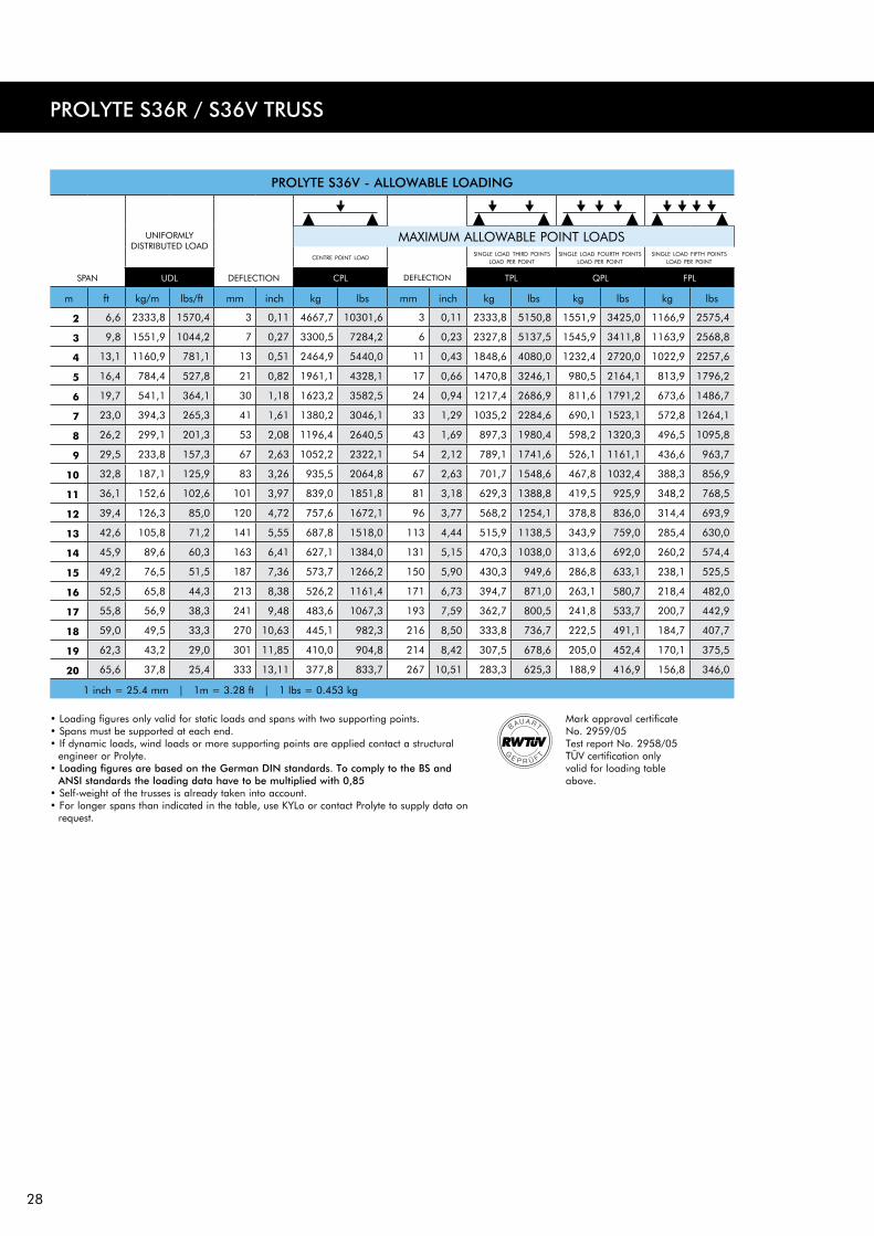
PROLYTE S36V - ALLOWABLE LOADINg
UNIFORMLYDISTRIBUTED LOAD
centre point load
SPAN UDL DEFLECTION CPL DEFLECTION TPL QPL FPL
m ft kg/m lbs/ft mm inch kg lbs mm inch kg lbs kg lbs kg lbs
2 6,6 2333,8 1570,4 3 0,11 4667,7 10301,6 3 0,11 2333,8 5150,8 1551,9 3425,0 1166,9 2575,4
3 9,8 1551,9 1044,2 7 0,27 3300,5 7284,2 6 0,23 2327,8 5137,5 1545,9 3411,8 1163,9 2568,8
4 13,1 1160,9 781,1 13 0,51 2464,9 5440,0 11 0,43 1848,6 4080,0 1232,4 2720,0 1022,9 2257,6
5 16,4 784,4 527,8 21 0,82 1961,1 4328,1 17 0,66 1470,8 3246,1 980,5 2164,1 813,9 1796,2
6 19,7 541,1 364,1 30 1,18 1623,2 3582,5 24 0,94 1217,4 2686,9 811,6 1791,2 673,6 1486,7
7 23,0 394,3 265,3 41 1,61 1380,2 3046,1 33 1,29 1035,2 2284,6 690,1 1523,1 572,8 1264,1
8 26,2 299,1 201,3 53 2,08 1196,4 2640,5 43 1,69 897,3 1980,4 598,2 1320,3 496,5 1095,8
9 29,5 233,8 157,3 67 2,63 1052,2 2322,1 54 2,12 789,1 1741,6 526,1 1161,1 436,6 963,7
10 32,8 187,1 125,9 83 3,26 935,5 2064,8 67 2,63 701,7 1548,6 467,8 1032,4 388,3 856,9
11 36,1 152,6 102,6 101 3,97 839,0 1851,8 81 3,18 629,3 1388,8 419,5 925,9 348,2 768,5
12 39,4 126,3 85,0 120 4,72 757,6 1672,1 96 3,77 568,2 1254,1 378,8 836,0 314,4 693,9
13 42,6 105,8 71,2 141 5,55 687,8 1518,0 113 4,44 515,9 1138,5 343,9 759,0 285,4 630,0
14 45,9 89,6 60,3 163 6,41 627,1 1384,0 131 5,15 470,3 1038,0 313,6 692,0 260,2 574,4
15 49,2 76,5 51,5 187 7,36 573,7 1266,2 150 5,90 430,3 949,6 286,8 633,1 238,1 525,5
16 52,5 65,8 44,3 213 8,38 526,2 1161,4 171 6,73 394,7 871,0 263,1 580,7 218,4 482,0
17 55,8 56,9 38,3 241 9,48 483,6 1067,3 193 7,59 362,7 800,5 241,8 533,7 200,7 442,9
18 59,0 49,5 33,3 270 10,63 445,1 982,3 216 8,50 333,8 736,7 222,5 491,1 184,7 407,7
19 62,3 43,2 29,0 301 11,85 410,0 904,8 214 8,42 307,5 678,6 205,0 452,4 170,1 375,5
20 65,6 37,8 25,4 333 13,11 377,8 833,7 267 10,51 283,3 625,3 188,9 416,9 156,8 346,0
1 inch = 25.4 mm | 1m = 3.28 ft | 1 lbs = 0.453 kg
single load fourth pointsload per point
single load fifth pointsload per point
single load third pointsload per point
MAXIMUM ALLOWABLE POINT LOADS
Mark approval certificate No. 2959/05Test report No. 2958/05TüV certification only valid for loading table above.
• Loading figures only valid for static loads and spans with two supporting points.• Spans must be supported at each end.• If dynamic loads, wind loads or more supporting points are applied contact a structural
engineer or Prolyte.• Loading figures are based on the german DIN standards. To comply to the BS and
ANSI standards the loading data have to be multiplied with 0,85• Self-weight of the trusses is already taken into account.• For longer spans than indicated in the table, use KYLo or contact Prolyte to supply data on
request.
29
PROLYTE S52F / S52S / S52SV TRUSS
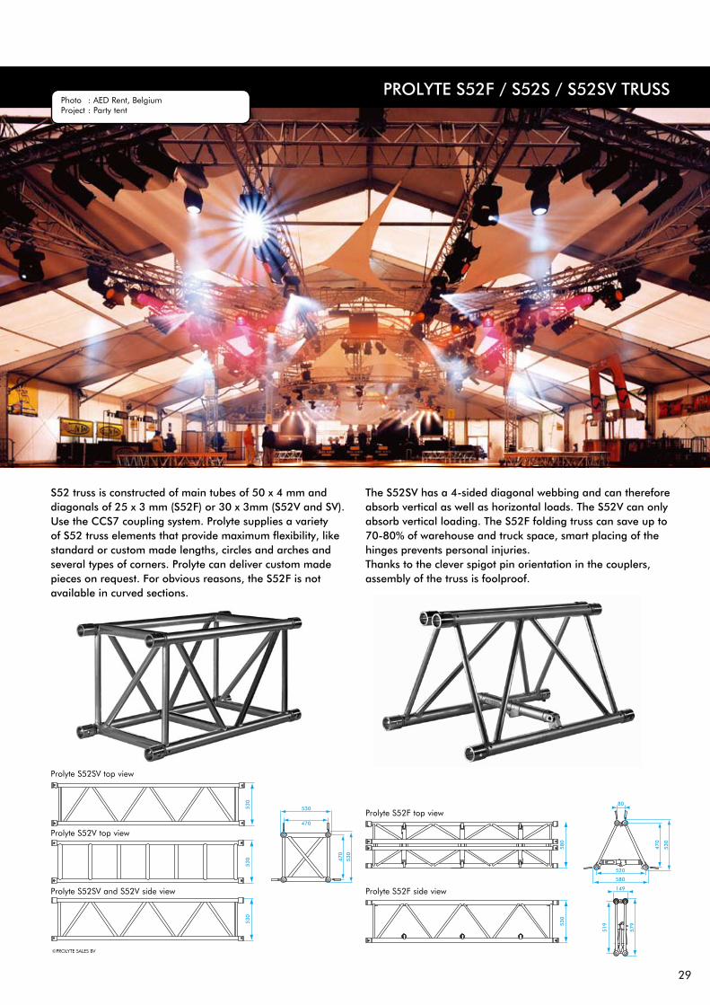
S52 truss is constructed of main tubes of 50 x 4 mm and diagonals of 25 x 3 mm (S52F) or 30 x 3mm (S52V and SV). Use the CCS7 coupling system. Prolyte supplies a variety of S52 truss elements that provide maximum flexibility, like standard or custom made lengths, circles and arches and several types of corners. Prolyte can deliver custom made pieces on request. For obvious reasons, the S52F is not available in curved sections.
The S52SV has a 4-sided diagonal webbing and can therefore absorb vertical as well as horizontal loads. The S52V can only absorb vertical loading. The S52F folding truss can save up to 70-80% of warehouse and truck space, smart placing of the hinges prevents personal injuries. Thanks to the clever spigot pin orientation in the couplers, assembly of the truss is foolproof.
Prolyte S52F top view
Prolyte S52F side view
Prolyte S52SV top view
Prolyte S52V top view
Prolyte S52SV and S52V side view
©PROLYTE SALES BV
Photo : AED Rent, Belgium Project : Party tent

30
PROLYTE S52F - ALLOWABLE LOADINg
UNIFORMLYDISTRIBUTED LOAD
centre point load
SPAN UDL DEFLECTION CPL DEFLECTION TPL QPL FPL
m ft kg/m lbs/ft mm inch kg lbs mm inch kg lbs kg lbs kg lbs
3 9,8 957,4 644,2 3 0,11 2393,5 5282,5 2 0,07 1196,7 2641,2 794,8 1754,2 598,4 1320,6
4 13,1 716,2 481,9 5 0,19 1944,1 4290,7 3 0,11 1193,7 2634,6 791,8 1747,6 596,9 1317,3
5 16,4 666,8 448,7 9 0,35 1549,9 3420,6 5 0,19 1162,4 2565,5 775,0 1710,3 595,4 1314,0
6 19,7 633,5 426,2 15 0,59 1414,7 3122,2 8 0,31 1061,0 2341,7 707,3 1561,1 587,1 1295,7
7 23,0 501,4 337,4 21 0,82 1206,5 2662,7 12 0,47 904,9 1997,0 603,2 1331,3 500,7 1105,0
8 26,2 429,3 288,9 31 1,22 1144,9 2526,7 16 0,62 858,7 1895,1 572,4 1263,4 475,1 1048,6
9 29,5 374,4 251,9 43 1,69 1095,1 2416,9 22 0,86 821,3 1812,7 547,6 1208,5 454,5 1003,0
10 32,8 301,0 202,5 53 2,08 978,2 2158,9 28 1,10 733,6 1619,1 489,1 1079,4 405,9 895,9
11 36,1 246,7 166,0 65 2,55 949,6 2095,9 36 1,41 712,2 1571,9 474,8 1047,9 394,1 869,8
12 39,4 205,3 138,2 77 3,03 924,1 2039,4 46 1,81 693,0 1529,6 462,0 1019,7 383,5 846,4
13 42,6 173,2 116,5 90 3,54 900,6 1987,7 58 2,28 675,5 1490,7 450,3 993,8 373,8 824,9
14 45,9 147,7 99,4 105 4,13 827,0 1825,3 67 2,63 620,3 1368,9 413,5 912,6 343,2 757,5
15 49,2 127,1 85,5 120 4,72 810,3 1788,3 82 3,22 607,7 1341,2 405,1 894,1 336,3 742,1
16 52,5 110,3 74,2 137 5,39 749,8 1654,7 93 3,66 562,3 1241,0 374,9 827,4 311,1 686,7
17 55,8 96,3 64,8 154 6,06 736,7 1625,9 111 4,37 552,5 1219,4 368,3 812,9 305,7 674,7
18 59,0 84,6 56,9 173 6,81 685,3 1512,4 125 4,92 513,9 1134,3 342,6 756,2 284,4 627,6
19 62,3 74,7 50,3 193 7,59 638,7 1409,5 139 5,47 479,0 1057,2 319,3 704,8 265,0 585,0
20 65,6 66,2 44,6 214 8,42 629,3 1388,9 162 6,37 472,0 1041,7 314,7 694,5 261,2 576,4
21 68,9 59,0 39,7 235 9,25 619,2 1366,6 188 7,40 464,4 1024,9 309,6 683,3 257,0 567,1
22 72,2 52,7 35,4 258 10,15 579,3 1278,6 207 8,14 434,5 958,9 289,7 639,3 240,4 530,6
23 75,4 47,2 31,7 282 11,10 542,4 1197,1 226 8,89 406,8 897,8 271,2 598,5 225,1 496,8
24 78,7 42,3 28,5 307 12,08 508,0 1121,3 246 9,68 381,0 840,9 254,0 560,6 210,8 465,3
1 inch = 25.4 mm | 1m = 3.28 ft | 1 lbs = 0.453 kg
single load fourth pointsload per point
single load fifth pointsload per point
single load third pointsload per point
MAXIMUM ALLOWABLE POINT LOADS
Mark approval certificate No. 860/96Test report No. 859/96TüV certification only valid for loading table above.
PROLYTE S52F / S52S / S52SV TRUSS
• Loading figures only valid for static loads and spans with two supporting points.• Spans must be supported at each end.• If dynamic loads, wind loads or more supporting points are applied contact a
structural engineer or Prolyte.• Loading figures are based on the german DIN standards. To comply to the
BS and ANSI standards the loading data have to be multiplied with 0,85• Self-weight of the trusses is already taken into account.• For longer spans than indicated in the table, use KYLo or contact Prolyte to
supply data on request.

31
PROLYTE S52SV AND S52V - ALLOWABLE LOADINg
UNIFORMLYDISTRIBUTED LOAD
centre point load
SPAN UDL DEFLECTION CPL DEFLECTION TPL QPL FPL
m ft kg/m lbs/ft mm inch kg lbs mm inch kg lbs kg lbs kg lbs
2 6,6 2864,0 1927,1 2 0,07 5728,0 12641,6 2 0,07 2864,0 6320,8 1904,3 4202,8 1432,0 3160,4
3 9,8 1904,3 1281,4 5 0,19 5193,9 11462,8 4 0,15 2856,5 6304,3 1896,8 4186,3 1428,2 3152,1
4 13,1 1424,5 958,5 9 0,35 3882,3 8568,2 7 0,27 2849,0 6287,7 1889,3 4169,7 1424,5 3143,9
5 16,4 1136,6 764,8 13 0,51 3092,3 6824,7 11 0,43 2319,2 5118,5 1546,2 3412,4 1283,3 2832,3
6 19,7 854,4 574,9 19 0,74 2563,2 5656,9 15 0,59 1922,4 4242,7 1281,6 2828,5 1063,7 2347,6
7 23,0 623,7 419,7 26 1,02 2183,1 4818,1 21 0,82 1637,3 3613,5 1091,5 2409,0 906,0 1999,5
8 26,2 474,0 319,0 34 1,33 1896,1 4184,8 27 1,06 1422,1 3138,6 948,1 2092,4 786,9 1736,7
9 29,5 371,4 249,9 43 1,69 1671,3 3688,5 35 1,37 1253,5 2766,4 835,6 1844,3 693,6 1530,7
10 32,8 298,0 200,5 53 2,08 1489,9 3288,2 43 1,69 1117,4 2466,2 745,0 1644,1 618,3 1364,6
11 36,1 243,7 164,0 65 2,55 1340,1 2957,7 52 2,04 1005,1 2218,3 670,1 1478,8 556,2 1227,4
12 39,4 202,3 136,2 77 3,03 1214,1 2679,5 62 2,44 910,6 2009,6 607,0 1339,7 503,8 1112,0
13 42,6 170,2 114,5 90 3,54 1106,3 2441,5 72 2,83 829,7 1831,2 553,1 1220,8 459,1 1013,2
14 45,9 144,7 97,4 105 4,13 1012,8 2235,2 84 3,30 759,6 1676,4 506,4 1117,6 420,3 927,6
15 49,2 124,1 83,5 120 4,72 930,8 2054,2 96 3,77 698,1 1540,7 465,4 1027,1 386,3 852,5
16 52,5 107,3 72,2 137 5,39 858,1 1893,8 109 4,29 643,5 1420,3 429,0 946,9 356,1 785,9
17 55,8 93,3 62,8 154 6,06 793,0 1750,2 123 4,84 594,8 1312,7 396,5 875,1 329,1 726,3
18 59,0 81,6 54,9 173 6,81 734,4 1620,8 138 5,43 550,8 1215,6 367,2 810,4 304,8 672,6
19 62,3 71,7 48,2 193 7,59 681,1 1503,3 154 6,06 510,9 1127,4 340,6 751,6 282,7 623,9
20 65,6 63,2 42,6 214 8,42 632,5 1395,8 171 6,73 474,3 1046,9 316,2 697,9 262,5 579,3
21 68,9 56,0 37,7 235 9,25 587,7 1297,0 188 7,40 440,8 972,8 293,8 648,5 243,9 538,3
22 72,2 49,7 33,4 258 10,15 546,3 1205,7 207 8,14 409,7 904,3 273,2 602,9 226,7 500,4
23 75,4 44,2 29,7 282 11,10 507,9 1120,9 226 8,89 380,9 840,7 253,9 560,5 210,8 465,2
24 78,7 39,3 26,5 307 12,08 472,0 1041,8 246 9,68 354,0 781,4 236,0 520,9 195,9 432,3
1 inch = 25.4 mm | 1m = 3.28 ft | 1 lbs = 0.453 kg
single load fourth pointsload per point
single load fifth pointsload per point
single load third pointsload per point
MAXIMUM ALLOWABLE POINT LOADS
S52SVMark approval certificate No. 2993/05Test report No. 2992/05TüV certification only valid for loading table above.
S52VMark approval certificate No. 2991/05Test report No. 2990/05TüV certification only valid for loading table above.
• Loading figures only valid for static loads and spans with two supporting points.• Spans must be supported at each end.• If dynamic loads, wind loads or more supporting points are applied contact a
structural engineer or Prolyte.• Loading figures are based on the german DIN standards. To comply to the
BS and ANSI standards the loading data have to be multiplied with 0,85• Self-weight of the trusses is already taken into account.• For longer spans than indicated in the table, use KYLo or contact Prolyte to
supply data on request.

32
S52V / SV / S52F SERIES - STANDARD AVAILABLE LENgTHS AND CODES
Meters Feet Code
0,25 / 1,00 m in steps of 5 mm
0,82’ / 3,28’ in steps of 0,2”
0,50 1,64 S52V/•-L050
0,60 1,97S52V/•-L060S52F-L050
0,80 2,62S52V/•-L080S52F-L060
1,00 3,28 S52V/•-L100
1,20 3,94S52V/•-L120S52F-L120
1,50 4,57 S52V/•-L150
1,60 5,25S52V/•-L160S52F-L160
2,00 6,56 S52V/•-L200
2,40 7,87S52V/•-L240S52F-L240
2,50 8,20 S52V/•-L250
3,00 9,84 S52V/•-L300
3,20 10,50 S52V/•-L320
4,00 13,12 S52V/•-L400
*on • indicate F for Folding, V for Square and SV for Square truss with 4-sited webbing. Example: S52V-L200
TECHNICAL SPECIFICATIONS S52 SERIES
TypesAlloy Main tubes (chords) Braces Coupling system
Type S52F S52V S52SV
Allowable Normal Force in Main Chord N 41,62 41,62 41,62 kN
Allowable Normal Force in Diagonals N 16,59 20,36 20,36 kN
Surface area Complete Truss A 23,12 23,12 23,12 cm2
Moment of Inertia Y-axis ly 10906,2 10906,2 10906,2 cm4
Moment of Inertia Z-axis lz 3650,0 10906,2 cm4
Allowable bending moment Y-axis My 39,12 39,12 39,12 kNm
Allowable bending moment Z-axis Mz 39,12 kNm
Allowable shear force Z-axis Qz/Vz 18,0 28,79 28,79 kN
Allowable shear force Y-axis Qy/Vy 28,79 kN
Selfweight kg 12 15 15 kg/m
Folding (F), Square (V)EN AW 6082 T650 x 4 mmS52F - 25 x 3 mm S52V/SV - 30 x 3 mmCCS7 series
PROLYTE S52F / S52S / S52SV TRUSS
33
PROLYTE S66R / S66V TRUSS
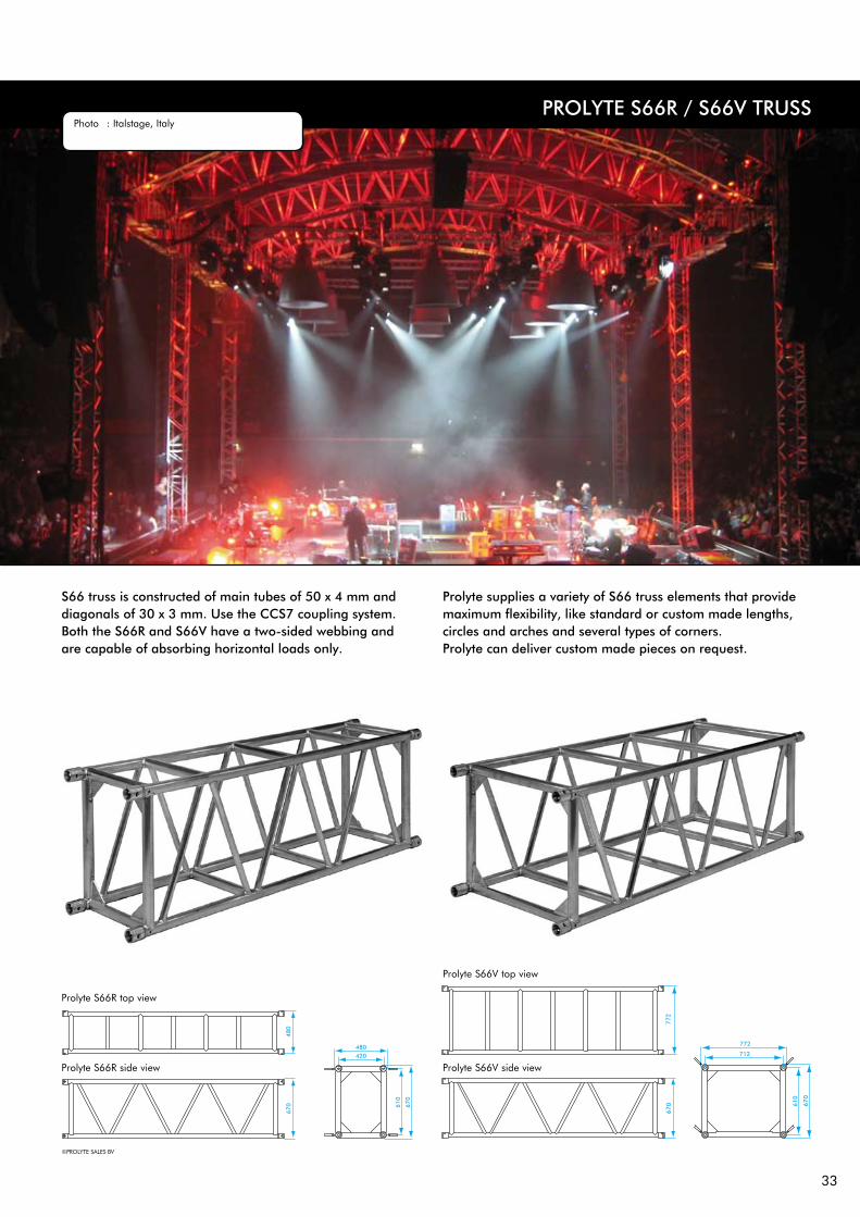
S66 truss is constructed of main tubes of 50 x 4 mm and diagonals of 30 x 3 mm. Use the CCS7 coupling system. Both the S66R and S66V have a two-sided webbing and are capable of absorbing horizontal loads only.
Prolyte supplies a variety of S66 truss elements that provide maximum flexibility, like standard or custom made lengths, circles and arches and several types of corners. Prolyte can deliver custom made pieces on request.
Prolyte S66V side view
Prolyte S66V top view
Prolyte S66R side view
Prolyte S66R top view
©PROLYTE SALES BV
Photo : Italstage, Italy
34
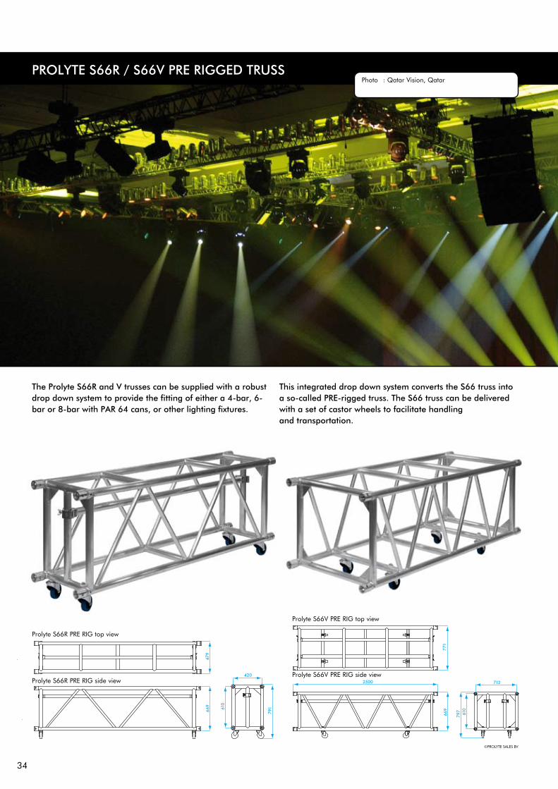
PROLYTE S66R / S66V PRE RIggED TRUSSPhoto : Qatar Vision, Qatar
Prolyte S66R PRE RIG side view
Prolyte S66R PRE RIG top view
©PROLYTE SALES BV
Prolyte S66V PRE RIG side view
Prolyte S66V PRE RIG top view
The Prolyte S66R and V trusses can be supplied with a robust drop down system to provide the fitting of either a 4-bar, 6-bar or 8-bar with PAR 64 cans, or other lighting fixtures.
This integrated drop down system converts the S66 truss into a so-called PRE-rigged truss. The S66 truss can be delivered with a set of castor wheels to facilitate handling and transportation.

35
PROLYTE S66R / S66V TRUSS
PROLYTE S66R AND S66V - ALLOWABLE LOADINg
UNIFORMLYDISTRIBUTED LOAD
centre point load
SPAN UDL DEFLECTION CPL DEFLECTION TPL QPL FPL
m ft kg/m lbs/ft mm inch kg lbs mm inch kg lbs kg lbs kg lbs
2 6,6 3106,6 2090,3 2 0,07 6213,2 13712,6 1 0,03 3106,6 6856,3 2065,4 4558,4 1553,3 3428,1
3 9,8 2065,4 1389,7 4 0,15 6196,2 13675,1 3 0,11 3098,1 6837,5 2056,9 4539,6 1549,1 3418,8
4 13,1 1544,8 1039,4 7 0,27 5043,6 11131,3 5 0,19 3089,6 6818,8 2048,4 4520,8 1544,8 3409,4
5 16,4 1232,4 829,3 10 0,39 4019,6 8871,2 8 0,31 3014,7 6653,4 2009,8 4435,6 1540,6 3400,0
6 19,7 1024,2 689,2 15 0,59 3334,1 7358,3 12 0,47 2500,6 5518,7 1667,0 3679,2 1383,6 3053,7
7 23,0 812,0 546,4 20 0,78 2842,0 6272,3 16 0,63 2131,5 4704,2 1421,0 3136,1 1179,4 2603,0
8 26,2 617,7 415,6 26 1,02 2470,8 5453,1 21 0,82 1853,1 4089,8 1235,4 2726,5 1025,4 2263,0
9 29,5 484,5 326,0 33 1,29 2180,2 4811,7 27 1,06 1635,2 3608,8 1090,1 2405,9 904,8 1996,9
10 32,8 389,2 261,9 41 1,61 1946,0 4294,9 33 1,29 1459,5 3221,2 973,0 2147,5 807,6 1782,4
11 36,1 318,7 214,4 50 1,96 1752,9 3868,7 40 1,57 1314,7 2901,5 876,5 1934,3 727,5 1605,5
12 39,4 265,1 178,4 59 2,23 1590,5 3510,3 47 1,85 1192,9 2632,7 795,3 1755,2 660,1 1456,8
13 42,6 223,4 150,3 70 2,75 1451,8 3204,2 56 2,20 1088,9 2403,2 725,9 1602,1 602,5 1329,8
14 45,9 190,2 128,0 81 3,18 1331,7 2939,2 65 2,55 998,8 2204,4 665,9 1469,6 552,7 1219,8
15 49,2 163,5 110,0 93 3,66 1226,5 2707,0 74 2,91 919,9 2030,2 613,3 1353,5 509,0 1123,4
16 52,5 141,7 95,3 105 4,13 1133,4 2501,4 84 3,30 580,1 1876,1 566,7 1250,7 470,4 1038,1
17 55,8 123,6 83,1 119 4,68 1050,2 2317,9 95 3,74 787,7 1738,4 525,1 1158,9 435,8 961,9
18 59,0 108,4 72,9 134 5,27 975,4 2152,6 107 4,21 731,5 1614,5 487,7 1076,3 404,8 893,3
19 62,3 95,5 64,3 149 5,86 907,5 2002,8 119 4,68 680,6 1502,1 453,7 1001,4 376,6 831,2
20 65,6 84,6 56,9 165 6,49 845,5 1866,1 132 5,19 634,1 1399,6 422,8 933,0 350,9 774,4
21 68,9 75,1 50,5 182 7,16 788,7 1740,6 145 5,70 591,5 1305,4 394,3 870,3 327,3 722,3
22 72,2 66,9 45,0 199 7,83 736,2 1624,8 160 6,29 552,2 1218,6 368,1 812,4 305,5 674,3
23 75,4 59,8 40,2 218 8,58 687,6 1517,5 174 6,85 515,7 1138,1 343,8 758,7 285,3 629,7
24 78,7 53,5 36,0 237 9,33 642,3 1417,5 190 7,48 481,7 1063,1 321,1 708,7 266,5 588,3
1 inch = 25.4 mm | 1m = 3.28 ft | 1 lbs = 0.453 kg
single load fourth pointsload per point
single load fifth pointsload per point
single load third pointsload per point
MAXIMUM ALLOWABLE POINT LOADS
S66RMark approval certificate No. 3075/05Test report No. 3074/05TüV certification only valid for loading table above.
S66VMark approval certificate No. 3073/05Test report No. 3072/05TüV certification only valid for loading table above.
• Loading figures only valid for static loads and spans with two supporting points.• Spans must be supported at each end.• If dynamic loads, wind loads or more supporting points are applied contact a structural
engineer or Prolyte.• Loading figures are based on the german DIN standards. To comply to the BS and ANSI
standards the loading data have to be multiplied with 0,85• Self-weight of the trusses is already taken into account.• For longer spans than indicated in the table, use KYLo or contact Prolyte to supply data on
request.

36
S66 SERIES - STANDARD AVAILABLE LENgTHS AND CODES
Meters Feet Code
0,25 / 1,00 m in steps of 5 mm
0,82’ / 3,28’ in steps of 0,2”
1,00 3,28 S66•-L100
1,50 4,92 S66•-L150
1,74* 5,71 S66•-L174 S66•PR-L174
2,00 6,56 S66•-L200
2,50* 8,20 S66•-L250 S66•PR-L250
3,00 9,84 S66•-L300
3,26* 10,69 S66•-L326 S66•PR-L326
3,50 11,48 S66•-L350
4,00 13,12 S66•-L400
*on • indicate R for Rectangle, V for Square truss. Example: S66V-L200
TECHNICAL SPECIFICATIONS S66 SERIES
TypesAlloy Main tubes (chords) Braces Coupling system
Type S66V S66R
Allowable Normal Force in Main Chord N 41,62 41,62 kN
Allowable Normal Force in Diagonals N 20,36 20,36 kN
Surface area Complete Truss A 23,12 23,12 cm2
Moment of Inertia Y-axis ly 18335,3 18335,3 cm4
Moment of Inertia Z-axis lz 3400,0 3550,0 cm4
Allowable bending moment Y-axis My 50,78 50,78 kNm
Allowable bending moment Z-axis Mz kNm
Allowable shear force Z-axis Qz/Vz 31,24 31,24 kN
Allowable shear force Y-axis Qy/Vy kN
Selfweight kg 17 17 kg/m
Rectangle (R), Square (V)EN AW 6082 T650 x 4 mm30 x 3 mmCCS7 series
PROLYTE S66R / S66V TRUSS

37
PROLYTE S100F TRUSS
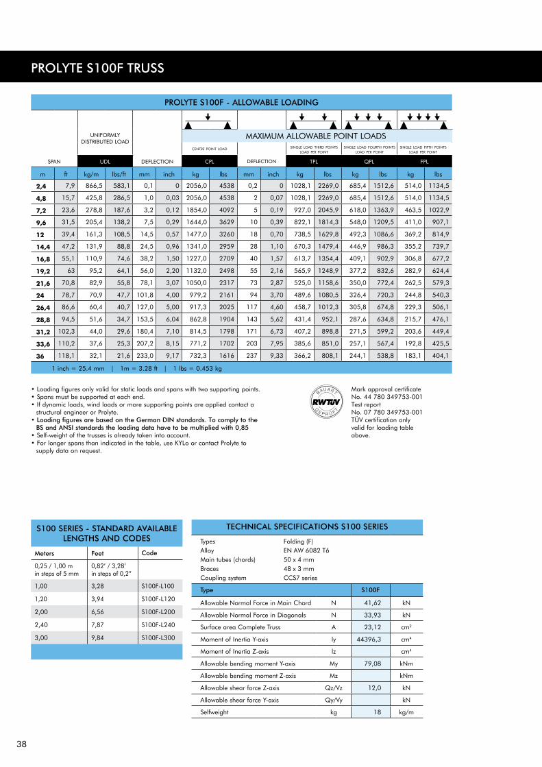
S100F truss is constructed of main tubes of 50 x 4 mm and diagonals of 48 x 3 mm. Use the CCS7 coupling system. Prolyte supplies a variety of S100 truss elements that provide maximum flexibility, like standard or custom made lengths and several types of corners. Prolyte can deliver custom made pieces on request. For obvious reasons, the S100F is not available in curved sections. Increased truss height and larger diagonals make it possible to create spans up to 30 metres.
The geometry of the bracing gives the possibility to combine the S100F truss with the S52F or S36R truss. Extra horizontal braces are welded between the diagonals to facilitate climbing of the truss for technicians. The S100F folding truss can save up to 70-80% of warehouse and truck space, clever placing of the hinges prevents the possibility of personal injuries. Thanks to the clever spigot pin orientation in the couplers, assembly of the truss is foolproof.
Prolyte S100 top view
Prolyte S100 side view
©PROLYTE SALES BV
Photo : AED RENT, Belgium Project : Fashion show
38
PROLYTE S100F - ALLOWABLE LOADINg
UNIFORMLYDISTRIBUTED LOAD
centre point load
SPAN UDL DEFLECTION CPL DEFLECTION TPL QPL FPL
m ft kg/m lbs/ft mm inch kg lbs mm inch kg lbs kg lbs kg lbs
2,4 7,9 866,5 583,1 0,1 0 2056,0 4538 0,2 0 1028,1 2269,0 685,4 1512,6 514,0 1134,5
4,8 15,7 425,8 286,5 1,0 0,03 2056,0 4538 2 0,07 1028,1 2269,0 685,4 1512,6 514,0 1134,5
7,2 23,6 278,8 187,6 3,2 0,12 1854,0 4092 5 0,19 927,0 2045,9 618,0 1363,9 463,5 1022,9
9,6 31,5 205,4 138,2 7,5 0,29 1644,0 3629 10 0,39 822,1 1814,3 548,0 1209,5 411,0 907,1
12 39,4 161,3 108,5 14,5 0,57 1477,0 3260 18 0,70 738,5 1629,8 492,3 1086,6 369,2 814,9
14,4 47,2 131,9 88,8 24,5 0,96 1341,0 2959 28 1,10 670,3 1479,4 446,9 986,3 355,2 739,7
16,8 55,1 110,9 74,6 38,2 1,50 1227,0 2709 40 1,57 613,7 1354,4 409,1 902,9 306,8 677,2
19,2 63 95,2 64,1 56,0 2,20 1132,0 2498 55 2,16 565,9 1248,9 377,2 832,6 282,9 624,4
21,6 70,8 82,9 55,8 78,1 3,07 1050,0 2317 73 2,87 525,0 1158,6 350,0 772,4 262,5 579,3
24 78,7 70,9 47,7 101,8 4,00 979,2 2161 94 3,70 489,6 1080,5 326,4 720,3 244,8 540,3
26,4 86,6 60,4 40,7 127,0 5,00 917,3 2025 117 4,60 458,7 1012,3 305,8 674,8 229,3 506,1
28,8 94,5 51,6 34,7 153,5 6,04 862,8 1904 143 5,62 431,4 952,1 287,6 634,8 215,7 476,1
31,2 102,3 44,0 29,6 180,4 7,10 814,5 1798 171 6,73 407,2 898,8 271,5 599,2 203,6 449,4
33,6 110,2 37,6 25,3 207,2 8,15 771,2 1702 203 7,95 385,6 851,0 257,1 567,4 192,8 425,5
36 118,1 32,1 21,6 233,0 9,17 732,3 1616 237 9,33 366,2 808,1 244,1 538,8 183,1 404,1
1 inch = 25.4 mm | 1m = 3.28 ft | 1 lbs = 0.453 kg
single load fourth pointsload per point
single load fifth pointsload per point
single load third pointsload per point
MAXIMUM ALLOWABLE POINT LOADS
Mark approval certificate No. 44 780 349753-001Test report No. 07 780 349753-001TüV certification only valid for loading table above.
TECHNICAL SPECIFICATIONS S100 SERIES
TypesAlloy Main tubes (chords) Braces Coupling system
Type S100F
Allowable Normal Force in Main Chord N 41,62 kN
Allowable Normal Force in Diagonals N 33,93 kN
Surface area Complete Truss A 23,12 cm2
Moment of Inertia Y-axis ly 44396,3 cm4
Moment of Inertia Z-axis lz cm4
Allowable bending moment Y-axis My 79,08 kNm
Allowable bending moment Z-axis Mz kNm
Allowable shear force Z-axis Qz/Vz 12,0 kN
Allowable shear force Y-axis Qy/Vy kN
Selfweight kg 18 kg/m
Folding (F)EN AW 6082 T650 x 4 mm48 x 3 mmCCS7 series
S100 SERIES - STANDARD AVAILABLE LENgTHS AND CODES
Meters Feet Code
0,25 / 1,00 m in steps of 5 mm
0,82’ / 3,28’ in steps of 0,2”
1,00 3,28 S100F-L100
1,20 3,94 S100F-L120
2,00 6,56 S100F-L200
2,40 7,87 S100F-L240
3,00 9,84 S100F-L300
PROLYTE S100F TRUSS
• Loading figures only valid for static loads and spans with two supporting points.• Spans must be supported at each end.• If dynamic loads, wind loads or more supporting points are applied contact a
structural engineer or Prolyte.• Loading figures are based on the german DIN standards. To comply to the
BS and ANSI standards the loading data have to be multiplied with 0,85• Self-weight of the trusses is already taken into account.• For longer spans than indicated in the table, use KYLo or contact Prolyte to
supply data on request.

39
PROLYTE B100RV
B100RV truss is constructed of main tubes of 60 x 6 mm and diagonals of 48 x 3 mm. Use the CCS7 coupling system. Prolyte supplies a variety of B100 truss elements that provide maximum flexibility, like standard or custom made lengths, circles and arches and some corners. Prolyte can deliver custom made pieces on request. The B100 truss is easy accessible for technicians, making it more safe to climb. Due to the 4-sided webbing of the B100 truss, it can absorb vertical as well as horizontal forces, which makes it ideal for outdoor use or 3 dimensional structures. The B100RV is standard equipped with a set of castors. These castors are positioned on the inside of the main chords, to allow for easy stacking of the truss for transportation purposes. Thanks to the clever spigot pin orientation in the couplers, assembly of the truss is foolproof.
Prolyte B100RV top view
Prolyte B100RV side view
Photo : ModifiC, Russian federationProject : Armenian festival
©PROLYTE SALES BV

40
PROLYTE B100RV TRUSS
PROLYTE B100RV - ALLOWABLE LOADINg
UNIFORMLYDISTRIBUTED LOAD
centre point load
SPAN UDL DEFLECTION CPL DEFLECTION TPL QPL FPL
m ft kg/m lbs/ft mm inch kg lbs mm inch kg lbs kg lbs kg lbs
2 6,6 6137,5 4129,7 1 0,03 12274,9 27090,8 1 0,03 6137,5 13545,4 4085,0 9015,5 3068,7 6772,7
3 9,8 4085,0 2748,6 2 0,07 12254,9 27046,6 2 0,07 6127,5 13523,3 4075,0 8993,5 3063,7 6761,7
4 13,1 3058,7 2058,1 4 0,15 12101,4 26707,9 3 0,11 6117,5 13501,3 4065,0 8971,4 3058,7 6750,6
5 16,4 2443,0 1643,8 6 0,24 9663,1 21326,6 5 0,19 6107,5 13479,2 4055,0 8949,3 3053,7 6739,6
6 19,7 2032,5 1367,6 8 0,31 8034,3 17731,7 7 0,27 6025,7 13298,8 4017,1 8865,8 3048,7 6728,6
7 23,0 1739,3 1170,3 11 0,43 6868,0 15157,6 9 0,35 5151,0 11368,2 3434,0 7578,8 2850,2 6290,4
8 26,2 1497,7 1007,7 15 0,59 5990,7 13221,5 12 0,47 4493,0 9916,1 2995,4 6610,8 2486,1 5486,9
9 29,5 1179,2 793,4 19 0,74 5306,2 11710,8 15 0,59 3979,6 8783,1 2653,1 5855,4 2202,1 4860,0
10 32,8 951,3 640,1 23 0,90 4756,6 10497,8 18 0,70 3567,4 7873,3 2378,3 5248,9 1974,0 4356,6
11 36,1 782,7 526,7 28 1,10 4305,1 9501,3 22 0,86 3228,8 7126,0 2152,5 4750,6 1786,6 3943,0
12 39,4 654,5 440,4 33 1,30 3927,1 8667,2 27 1,06 2945,4 6500,4 1963,6 4333,6 1629,8 3596,9
13 42,6 554,7 373,3 39 1,53 3605,8 7958,1 31 1,22 2704,4 5968,5 1802,9 3979,0 1496,4 3302,6
14 45,9 475,6 320,0 45 1,77 3329,0 7347,1 36 1,41 2496,7 5510,3 1664,5 3673,5 1381,5 3049,0
15 49,2 411,7 277,0 52 2,04 3087,7 6814,6 42 1,65 2315,8 5110,9 1543,9 3407,3 1281,4 2828,1
16 52,5 359,4 241,8 59 2,32 2875,4 6345,9 47 1,85 2156,5 4759,4 1437,7 3173,0 1193,3 2633,6
17 55,8 316,1 212,7 67 2,63 2686,8 5929,8 53 2,08 2015,1 4447,3 1343,4 2964,9 1115,0 2460,9
18 59,0 279,8 188,3 75 2,95 2518,1 5557,4 60 2,36 1888,6 4168,1 1259,0 2778,7 1045,0 2306,3
19 62,3 249,1 167,6 83 3,26 2366,1 5222,0 67 2,63 1774,6 3916,5 1183,0 2611,0 981,9 2167,1
20 65,6 222,8 149,9 92 3,62 2228,3 4917,8 74 2,91 1671,2 3688,4 1114,1 2458,9 924,7 2040,9
21 68,9 200,3 134,7 102 4,01 2102,7 4640,6 82 3,22 1577,0 3480,4 1051,3 2320,3 872,6 1925,8
22 72,2 180,7 121,6 112 4,40 1987,5 4386,5 89 3,50 1490,7 3289,9 993,8 2193,2 824,8 1820,4
23 75,4 163,6 110,1 122 4,80 1881,6 4152,6 98 3,85 1411,2 3114,4 940,8 2076,3 780,8 1723,3
24 78,7 148,6 100,0 133 5,23 1783,6 3936,3 106 4,17 1337,7 2952,3 891,8 1968,2 740,2 1633,6
25 82,0 135,4 91,1 144 5,66 1692,6 3735,6 116 4,56 1269,5 2801,7 846,3 1867,8 702,4 1550,3
26 85,3 123,7 83,2 156 6,14 1607,9 3548,7 125 4,92 1205,9 2661,5 804,0 1774,3 667,3 1472,7
27 88,6 113,2 76,2 168 6,61 1528,7 3373,9 135 5,31 1146,5 2530,4 764,4 1687,0 634,4 1400,2
28 91,8 103,9 69,9 181 7,12 1454,5 3210,1 145 5,70 1090,9 2407,5 727,2 1605,0 603,6 1332,2
29 95,1 95,5 64,3 194 7,63 1384,7 3056,0 155 6,10 1038,5 2292,0 692,3 1528,0 574,6 1268,2
30 98,4 87,9 59,2 208 8,18 1318,9 2910,7 166 6,53 989,1 2183,0 659,4 1455,4 547,3 1207,9
31 101,7 81,1 54,6 222 8,74 1256,6 2773,4 178 7,00 942,5 2080,0 628,3 1386,7 521,5 1151,0
32 105,0 74,9 50,4 237 9,33 1197,7 2643,3 189 7,44 898,3 1982,5 598,8 1321,6 497,0 1097,0
33 108,2 69,2 46,6 252 9,92 1141,7 2519,7 201 7,91 856,3 1889,8 570,8 1259,9 473,8 1045,7
34 111,5 64,0 43,1 267 10,51 1088,4 2402,1 214 8,42 816,3 1081,6 544,2 1201,1 451,7 996,9
35 114,8 59,3 39,9 283 11,14 1037,6 2290,0 226 8,89 778,2 1717,5 518,8 1145,0 430,6 950,3
36 118,1 54,9 37,0 299 11,77 989,0 2182,8 240 9,44 741,8 1637,1 494,5 1091,4 410,5 905,9
37 121,4 51,0 34,3 316 12,44 942,6 2080,3 253 9,96 706,9 1560,2 471,3 1040,1 391,2 863,3
38 124,6 47,3 31,8 334 13,14 898,0 1982,0 267 10,51 673,5 1486,5 449,0 991,0 372,7 822,5
39 127,9 43,9 29,5 351 13,81 855,3 1887,6 281 11,06 641,5 1415,7 427,6 943,8 354,9 783,4
40 131,2 40,7 27,4 370 14,56 814,1 1796,8 296 11,65 610,6 1347,6 407,1 898,4 337,9 745,7
1 inch = 25.4 mm | 1m = 3.28 ft | 1 lbs = 0.453 kg
single load fourth points single load fifth pointssingle load third points
MAXIMUM ALLOWABLE POINT LOADS
Mark approval certificate No. 2733/03Test report No. TüV certification only valid for loading table above.
• Loading figures only valid for static loads and spans with two supporting points.• Spans must be supported at each end.• If dynamic loads, wind loads or more supporting points are applied contact a structural engineer or Prolyte.• Loading figures are based on the german DIN standards. To comply to the BS and ANSI standards the
loading data have to be multiplied with 0,85• Self-weight of the trusses is already taken into account.• For longer spans than indicated in the table, use KYLo or contact Prolyte to supply data on request.

41
PROLYTE CATWALK TRUSS
The Prolyft catwalk truss (B100RV-CW) is designed based on the B100V truss. It can be used to create mother grids or working platforms as well as proscenium or lighting bridges in a theatrical environment. The B100RV-CW truss is fitted with an extra handrail on top and a reinforced plate on the bottom side to create a walking platform.
The catwalk truss can be flown by assembling bracing bars with fixed lifting eyes to the bottom braces of the truss. The catwalk truss is designed and manufactured in compliance with: DIN 1055, DIN 18800, DIN 4112, DIN 4112/A1, DIN 4113-1, DIN 4113-1/A1, DIN 4113-2.
B100RV SERIES - STANDARD AVAILABLE LENgTHS AND CODES
Meters Feet Code
0,25 / 1,00 m in steps of 5 mm
0,82’ / 3,28’ in steps of 0,2”
1,00 3,28 B100RV•-L100
1,20 3,94 B100RV•-L120
2,00 6,56 B100RV•-L200
2,40 7,87 B100RV•-L240
3,00 9,84 B100RV•-L300
TECHNICAL SPECIFICATIONS B100 SERIES
TypesAlloy Main tubes (chords) Braces Coupling system
Type B100RV
Allowable Normal Force in Main Chord N 63,90 kN
Allowable Normal Force in Diagonals N 33,93 kN
Surface area Complete Truss A 40,72 cm2
Moment of Inertia Y-axis ly 78211,5 cm4
Moment of Inertia Z-axis lz 23522,6 cm4
Allowable bending moment Y-axis My 121,41 kNm
Allowable bending moment Z-axis Mz 66,46 kNm
Allowable shear force Z-axis Qz/Vz 61,57 kN
Allowable shear force Y-axis Qy/Vy 31,08 kN
Selfweight kg 25 kg/m
Rectangle (R), Square (V)EN AW 6082 T660 x 6 mm48 x 3 mmCCS7 series
Photo : Jan Hoefnagel, Flashlight Rental BV, The Netherlands Project : Blue Man Group
43
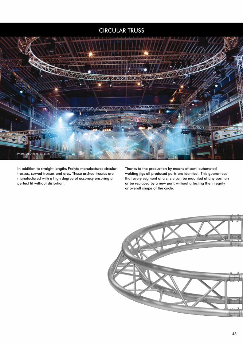
CIRCULAR TRUSS
Photo: AED Rent, Belgium
In addition to straight lengths Prolyte manufactures circular trusses, curved trusses and arcs. These arched trusses are manufactured with a high degree of accuracy ensuring a perfect fit without distortion.
Thanks to the production by means of semi automated welding jigs all produced parts are identical. This guarantees that every segment of a circle can be mounted at any position or be replaced by a new part, without affecting the integrity or overall shape of the circle.

44
PROLYTE CIRCULAR TRUSS
APEX IN APEX OUT APEX DOWN/UP
Circular or curved trusses are manufactured in different diameters or degrees. If you order a complete circular truss you have to indicate the amount of cuttings wanted (each segment requires one cut). Couplers do not have to be ordered separately, they are included in the ordered amount of cuttings.
A “cutting” divides the circle into segments. Individual segments cannot be longer than 5 meters, Prolyte would like to advise segment lengths between 3-4 metres. For further reference please read our “Technical Matters”.
Photo: PRO 1, Project: Wella fashion show

45
PROLYTE E20 CIRCULAR TRUSS
PROLYTE E20D CIRCULAR TRUSS - ALLOWABLE LOADING3 SUSPENSION POINTS 4 SUSPENSION POINTS 6 SUSPENSION POINTS 8 SUSPENSION POINTS 10 SUSPENSION POINTS
DIAMETER UDL CPL UDL CPL UDL CPL UDL CPL UDL CPL
m ft kg/m LBS/ft kg LBS kg/m LBS/ft kg LBS kg/m LBS/ft kg LBS kg/m LBS/ft kg LBS kg/m LBS/ft kg LBS
4,00 13,1 18 11,85 48 107 33 22,11 72 158 69 46,66 113 249 108 72,69 142 314 146 98,60 162 358
6,00 19,7 8 5,61 35 76 17 11,39 53 118 39 26,46 91 200 65 43,50 121 267 91 60,91 144 318
8,00 26,2 5 3,09 27 59 10 6,82 42 93 26 17,17 76 167 44 29,52 105 232 63 42,51 129 285
10,00 32,8 3 1,82 22 48 7 4,43 35 77 18 12,03 65 143 32 21,51 93 205 47 31,76 117 258
12,00 39,4 - - - 0 4 3,02 30 66 13 8,85 57 125 24 16,42 83 184 37 24,79 107 236
14,00 45,9 - - - 0 3 2,12 26 57 10 6,75 50 111 19 12,94 75 166 30 19,96 98 217
PROLYTE E20V CIRCULAR TRUSS - ALLOWABLE LOADING3 SUSPENSION POINTS 4 SUSPENSION POINTS 6 SUSPENSION POINTS 8 SUSPENSION POINTS 10 SUSPENSION POINTS
DIAMETER UDL CPL UDL CPL UDL CPL UDL CPL UDL CPL
m ft kg/m LBS/ft kg LBS kg/m LBS/ft kg LBS kg/m LBS/ft kg LBS kg/m LBS/ft kg LBS kg/m LBS/ft kg LBS
4,00 13,1 30 20,43 91 200 51 34,46 123 272 96 64,29 170 376 140 93,93 198 436 183 122,93 214 472
6,00 19,7 16 10,59 68 150 29 19,20 98 216 58 38,73 146 323 87 58,74 178 394 117 78,45 199 439
8,00 26,2 9 6,32 54 120 18 12,24 81 178 39 26,41 128 283 62 41,43 162 359 84 56,40 186 410
10,00 32,8 6 4,07 45 99 12 8,41 69 151 29 19,30 114 251 46 31,24 149 329 64 43,29 174 384
12,00 39,4 4 2,73 38 84 9 6,06 59 131 22 14,75 102 225 37 24,59 137 303 51 34,64 164 362
14,00 45,9 - - - 0 7 4,50 52 116 17 11,64 93 204 30 19,93 127 281 42 28,54 155 341
All loading figures are based on Uniformly Divided Suspension points and a suspended load in each of the fields. In all other cases this loading data is NOT valid. If loads are unevenly divided, instability will occur. For more details and loading figures of other diameters we refer to our website. • Absence of diagonal braces in top and/or bottom side of the truss causes dramatic reduction of the allowable loading. A structural report per situation
is required for these models. • Loading figures are based on the German DIN standards. To comply to the BS and ANSI standards the loading data have to be multiplied with 0,85.
Photo: Chritto, Germany

46
PROLYTE X30D CIRCULAR TRUSS - ALLOWABLE LOADING3 SUSPENSION POINTS 4 SUSPENSION POINTS 6 SUSPENSION POINTS 8 SUSPENSION POINTS 10 SUSPENSION POINTS
DIAMETER UDL CPL UDL CPL UDL CPL UDL CPL UDL CPL
m ft kg/m LBS/ft kg LBS kg/m LBS/ft kg LBS kg/m LBS/ft kg LBS kg/m LBS/ft kg LBS kg/m LBS/ft kg LBS
4,00 13,1 110 73,76 302 667 195 131,02 434 958 389 262,13 652 1440 590 397,37 798 1762 789 530,79 892 1968
6,00 19,7 55 37,30 220 486 105 70,52 331 731 227 153,00 538 1187 361 242,76 695 1534 495 333,00 806 1779
8,00 26,2 33 22,22 173 382 66 44,08 267 590 151 101,88 457 1009 249 167,90 616 1359 350 235,76 735 1623
10,00 32,8 22 14,51 142 314 45 30,04 224 494 107 72,08 374 825 185 124,52 503 1110 265 178,54 631 1394
12,00 39,4 15 10,04 121 267 32 21,21 193 425 74 49,60 309 681 133 89,34 417 921 209 140,45 524 1158
14,00 45,9 11 7,22 105 231 23 15,18 165 365 54 36,04 262 578 97 65,24 355 784 153 102,79 448 989
PROLYTE H30D CIRCULAR TRUSS - ALLOWABLE LOADING3 SUSPENSION POINTS 4 SUSPENSION POINTS 6 SUSPENSION POINTS 8 SUSPENSION POINTS 10 SUSPENSION POINTS
DIAMETER UDL CPL UDL CPL UDL CPL UDL CPL UDL CPL
m ft kg/m LBS/ft kg LBS kg/m LBS/ft kg LBS kg/m LBS/ft kg LBS kg/m LBS/ft kg LBS kg/m LBS/ft kg LBS
4,00 13,1 114 76,81 316 698 203 136,93 455 1004 408 274,59 684 1509 619 416,60 837 1848 827 556,69 935 2065
6,00 19,7 57 38,52 230 508 109 73,40 346 765 238 160,01 563 1243 378 254,25 729 1609 519 349,01 845 1866
8,00 26,2 34 22,69 181 399 68 45,64 279 617 158 106,32 478 1056 261 175,64 645 1424 367 246,91 771 1701
10,00 32,8 22 14,60 148 328 46 30,91 234 516 113 76,16 416 918 193 130,11 551 1216 278 186,82 674 1488
12,00 39,4 15 10,04 126 278 33 22,10 201 443 85 57,30 362 798 150 100,83 467 1031 219 147,61 588 1298
14,00 45,9 11 7,22 109 240 24 16,41 176 388 63 42,10 306 675 114 76,58 397 877 179 120,21 502 1107
PROLYTE X30V CIRCULAR TRUSS - ALLOWABLE LOADING3 SUSPENSION POINTS 4 SUSPENSION POINTS 6 SUSPENSION POINTS 8 SUSPENSION POINTS 10 SUSPENSION POINTS
DIAMETER UDL CPL UDL CPL UDL CPL UDL CPL UDL CPL
m ft kg/m LBS/ft kg LBS kg/m LBS/ft kg LBS kg/m LBS/ft kg LBS kg/m LBS/ft kg LBS kg/m LBS/ft kg LBS
4,00 13,1 179 120,57 547 1208 291 195,52 721 1592 521 350,60 952 2102 747 503,05 1078 2380 969 652,14 1149 2537
6,00 19,7 97 65,53 422 933 167 112,70 588 1297 320 215,57 838 1849 474 318,95 991 2187 624 420,28 1084 2392
8,00 26,2 61 41,10 343 758 110 74,15 495 1093 223 149,85 747 1649 339 227,94 916 2022 453 304,97 1025 2263
10,00 32,8 42 27,96 289 637 78 52,62 427 944 166 111,58 674 1488 259 174,06 852 1880 351 236,25 972 2146
12,00 39,4 30 20,05 248 549 58 39,23 376 829 129 86,85 614 1355 206 138,67 796 1757 283 190,78 924 2040
14,00 45,9 22 14,89 218 481 45 30,27 335 739 104 69,75 563 1242 169 113,79 746 1648 236 158,57 881 1944
PROLYTE H30V CIRCULAR TRUSS - ALLOWABLE LOADING3 SUSPENSION POINTS 4 SUSPENSION POINTS 6 SUSPENSION POINTS 8 SUSPENSION POINTS 10 SUSPENSION POINTS
DIAMETER UDL CPL UDL CPL UDL CPL UDL CPL UDL CPL
m ft kg/m LBS/ft kg LBS kg/m LBS/ft kg LBS kg/m LBS/ft kg LBS kg/m LBS/ft kg LBS kg/m LBS/ft kg LBS
4,00 13,1 187 125,98 573 1264 304 204,56 755 1667 546 367,39 998 2203 785 528,21 1130 2495 1016 684,00 1206 2661
6,00 19,7 101 68,13 441 974 175 117,59 615 1357 335 225,61 877 1937 498 334,90 1038 2292 655 440,55 1136 2508
8,00 26,2 63 42,45 358 790 115 77,12 517 1142 233 156,61 782 1726 356 239,34 960 2118 475 319,48 1074 2371
10,00 32,8 43 28,65 300 663 81 54,51 446 984 173 116,41 705 1556 272 182,77 892 1968 367 247,31 1018 2247
12,00 39,4 30 20,33 258 570 60 40,44 391 864 134 90,45 641 1415 216 145,60 832 1837 297 199,57 967 2136
14,00 45,9 22 14,91 226 499 46 31,04 348 769 108 72,49 587 1297 178 119,48 780 1722 246 165,76 921 2034
PROLYTE X/H 30 CIRCULAR TRUSS
All loading figures are based on Uniformly Divided Suspension points and a suspended load in each of the fields. In all other cases this loading data is NOT valid. If loads are unevenly divided, instability will occur. For more details and loading figures of other diameters we refer to our website. • Absence of diagonal braces in top and/or bottom side of the truss causes dramatic reduction of the allowable loading. A structural report per situation
is required for these models. • Loading figures are based on the German DIN standards. To comply to the BS and ANSI standards the loading data have to be multiplied with 0,85.

47
PROLYTE H40, S36V AND S52SV CIRCULAR TRUSS
PROLYTE S36V CIRCULAR TRUSS - ALLOWABLE LOADING3 SUSPENSION POINTS 4 SUSPENSION POINTS 6 SUSPENSION POINTS 8 SUSPENSION POINTS 10 SUSPENSION POINTS
DIAMETER UDL CPL UDL CPL UDL CPL UDL CPL UDL CPL
m ft kg/m LBS/ft kg LBS kg/m LBS/ft kg LBS kg/m LBS/ft kg LBS kg/m LBS/ft kg LBS kg/m LBS/ft kg LBS
4,00 13,1 461 310,2 1458 3218 727 489,6 1864 4115 1268 853,3 2370 5232 1796 1208,7 2630 5805 2313 1556,6 2773 6121
6,00 19,7 256 172,6 1150 2538 428 287,9 1554 3430 790 531,6 2124 4688 1149 773,0 2450 5409 1499 1009,2 2641 5830
8,00 26,2 164 110,3 947 2091 286 192,6 1330 2936 555 373,8 1922 4244 827 556,9 2293 5061 1094 736,5 2521 5564
10,00 32,8 113 76,2 804 1774 206 138,5 1162 2564 418 281,2 1755 3875 637 428,4 2154 4754 825 573,6 2410 5321
12,00 39,4 82 55,4 697 1539 155 104,5 1030 2273 328 220,9 1614 3563 511 343,7 2030 4481 692 465,6 2309 5097
14,00 45,9 62 41,7 614 1356 121 81,5 923 2038 266 178,9 1437 3172 422 283,8 1919 4237 578 388,9 2216 4891
PROLYTE S52SV CIRCULAR TRUSS - ALLOWABLE LOADING3 SUSPENSION POINTS 4 SUSPENSION POINTS 6 SUSPENSION POINTS 8 SUSPENSION POINTS 10 SUSPENSION POINTS
DIAMETER UDL CPL UDL CPL UDL CPL UDL CPL UDL CPL
m ft kg/m LBS/ft kg LBS kg/m LBS/ft kg LBS kg/m LBS/ft kg LBS kg/m LBS/ft kg LBS kg/m LBS/ft kg LBS
4,00 13,1 653 439,5 2208 4874 983 661,6 2666 5885 1635 1100,6 3170 6998 2271 1528,2 3405 7515 2895 1948,3 3528 7787
6,00 19,7 380 255,8 1822 4023 599 403,0 2320 5121 1041 700,3 2931 6471 1472 990,5 3243 7158 1894 1274,7 3413 7534
8,00 26,2 252 169,5 1549 3419 413 277,7 2051 4528 746 502,0 2725 6016 1074 722,7 3095 6831 1394 938,4 3305 7297
10,00 32,8 179 120,8 1344 2968 305 205,0 1836 4054 571 384,4 2545 5618 836 562,6 2959 6532 1095 737,1 3204 7073
12,00 39,4 134 90,3 1186 2618 235 158,3 1661 3667 456 306,9 2386 5268 678 456,5 2834 6257 896 603,2 3108 6862
14,00 45,9 104 69,7 1060 2339 187 126,0 1473 3251 375 252,4 2246 4957 566 381,2 2719 6003 754 507,8 3018 6662
PROLYTE H40D CIRCULAR TRUSS - ALLOWABLE LOADING3 SUSPENSION POINTS 4 SUSPENSION POINTS 6 SUSPENSION POINTS 8 SUSPENSION POINTS 10 SUSPENSION POINTS
DIAMETER UDL CPL UDL CPL UDL CPL UDL CPL UDL CPL
m ft kg/m LBS/ft kg LBS kg/m LBS/ft kg LBS kg/m LBS/ft kg LBS kg/m LBS/ft kg LBS kg/m LBS/ft kg LBS
4,00 13,1 170 114,64 494 1091 289 194,30 681 1502 544 366,38 957 2112 800 538,53 1122 2477 1051 707,13 1221 2696
6,00 19,7 89 60,06 370 818 161 108,34 537 1184 327 220,03 816 1801 499 335,95 1006 2222 669 450,50 1130 2495
8,00 26,2 54 36,66 296 653 103 69,49 442 976 223 149,92 711 1570 352 236,60 912 2014 481 323,42 1052 2322
10,00 32,8 36 24,40 246 542 72 48,30 376 830 163 109,71 597 1319 265 178,29 804 1774 369 248,05 983 2171
12,00 39,4 25 17,16 210 463 50 33,92 317 699 118 79,25 493 1089 209 140,34 666 1471 295 198,44 838 1849
14,00 45,9 19 12,51 183 404 36 24,29 265 584 86 57,60 418 923 155 104,24 568 1253 243 163,49 715 1579
PROLYTE H40V CIRCULAR TRUSS - ALLOWABLE LOADING3 SUSPENSION POINTS 4 SUSPENSION POINTS 6 SUSPENSION POINTS 8 SUSPENSION POINTS 10 SUSPENSION POINTS
DIAMETER UDL CPL UDL CPL UDL CPL UDL CPL UDL CPL
m ft kg/m LBS/ft kg LBS kg/m LBS/ft kg LBS kg/m LBS/ft kg LBS kg/m LBS/ft kg LBS kg/m LBS/ft kg LBS
4,00 13,1 263 176,86 847 1871 409 275,34 1066 2354 703 473,14 1329 2954 990 666,05 1460 3223 1270 855,03 1531 3380
6,00 19,7 148 99,67 677 1494 243 163,58 900 1986 441 296,64 1202 2654 636 427,71 1369 3023 826 555,89 1465 3235
8,00 26,2 96 64,28 562 1240 164 110,32 777 1715 312 209,78 1097 2421 460 309,30 1289 2846 604 406,76 1405 3101
10,00 32,8 67 44,76 480 1059 119 79,92 683 1508 236 158,63 1008 2225 355 238,80 1217 2687 472 317,61 1349 2978
12,00 39,4 49 32,75 418 922 90 60,65 609 1344 186 125,20 932 2057 286 192,20 1153 2545 384 258,43 1297 2863
14,00 45,9 37 24,79 369 815 71 47,55 548 1211 151 101,83 866 1912 237 159,25 1095 2416 321 216,36 1249 2757
All loading figures are based on Uniformly Divided Suspension points and a suspended load in each of the fields. In all other cases this loading data is NOT valid. If loads are unevenly divided, instability will occur. For more details and loading figures of other diameters we refer to our website. • Absence of diagonal braces in top and/or bottom side of the truss causes dramatic reduction of the allowable loading. A structural report per situation
is required for these models. • Loading figures are based on the German DIN standards. To comply to the BS and ANSI standards the loading data have to be multiplied with 0,85.
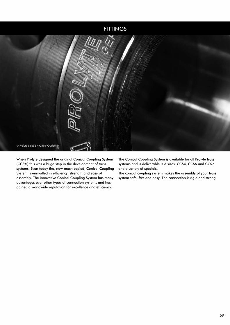
69
FITTINGS
When Prolyte designed the original Conical Coupling System (CCS®) this was a huge step in the development of truss systems. Even today the, now much copied, Conical Coupling System is unrivalled in efficiency, strength and easy of assembly. The innovative Conical Coupling System has many advantages over other types of connection systems and has gained a worldwide reputation for excellence and efficiency.
The Conical Coupling System is available for all Prolyte truss systems and is deliverable is 3 sizes, CCS4, CCS6 and CCS7 and a variety of specials. The conical coupling system makes the assembly of your truss system safe, fast and easy. The connection is rigid and strong.
© Prolyte Sales BV. Omke Oudeman

70
FITTINGS CCS4
CCS4-400 Weight = 0,058 kgConical coupler
CCS6-605 Weight = 0,003 kgSafety R-spring
CCS4-403 Weight = 0,017 kgSpigot To be used with CCS6-605
safety R-spring
CCS4-404 Weight = 0,017 kgSpigot with thread M6 To be used with selflocking nut M6CCS4-404RF (stainless steel)
CCS4-402 Weight = 0,050 kgOffset half Conical coupler Offset 15 mm, thread M6
CCS4-450 Weight = 0,029 kgHalf Conical coupler Offset 0 mm, thread M6
CCS4-451 Weight = 0,065 kgFemale conical coupler With 9 mm hole for bolts M8
CCS4-S05 through CCS4-S50 Weight = 0,070 - 0,170 kgSpacers X= 5 mm to 50 mm in steps of
5 mm
BASE 20D Weight = 0,740 kgBaseplate for E20D truss
BASE 20V Weight = 1,170 kgBaseplate for E20V truss

71
FITTINGS CCS6
CCS6-600 Weight = 0,148 kgConical coupler
CCS6-605 Weight = 0,003 kgSafety R-spring
CCS6-603 Weight = 0,042 kgSpigot To be used with CCS6-605 safety
R-spring
CCS6-604 Weight = 0,040 kgSpigot with thread M8 To be used with selflocking nut M8CCS6-604RF (stainless steel)
CCS6-602 Weight = 0,116kgOffset half Conical coupler Offset 19 mm, thread M12
CCS6-650 Weight = 0,069 kgHalf Conical coupler Offset 0 mm, thread M12
CCS6-651 Weight = 0,280 kgFemale conical coupler With 12,5 mm hole for bolts M12
CCS6-S05 through CCS6-S50 Weight = 0,187 - 0,404 kgSpacers X= 5 mm to 50 mm in steps
of 5 mm
CCS6-H Weight = 0,590 kgHinge for MPT Tower or ST Tower, 4 hinges per tower needed.See part 3, Miscellaneous, for the use of hinges in different set-ups.
CCS6-652Male coupler 600 half, hole M12. BM-12 x 028-652. Bolt M12 x 028 bolt for CCS6-652

72
FITTINGS CCS6
FITTINGS CCS7
BASE 30D Weight = 1,160 kgBaseplate for X•H30D truss
BASE 30V Weight = 1,860 kgBaseplate for X•H30V truss
BASE 40D Weight = 2,700 kgBaseplate for H40D truss
BASE 40V Weight = 2,820 kgBaseplate for H40V truss
BASE 36V Weight = 1,160 kgBaseplate for 36V truss
BASE 36R Weight = 1,860 kgBaseplate for 36R truss
BASE 52V Weight = 2,700 kgBaseplate for 52V truss
CCS7-H-FM-BOLT Weight = 0,326 kg
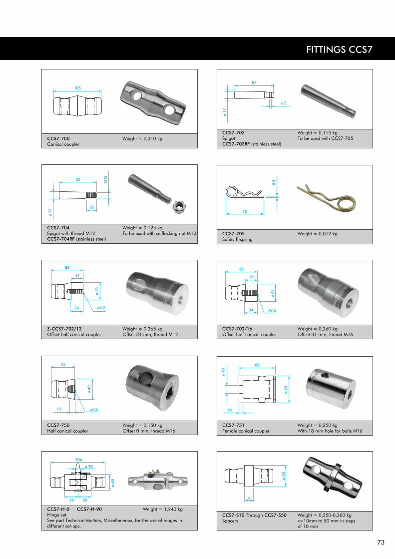
73
83
FITTINGS CCS7
CCS7-700 Weight = 0,310 kgConical coupler
CCS7-703 Weight = 0,115 kgSpigot To be used with CCS7-705CCS7-703RF (stainless steel)
CCS7-702/16 Weight = 0,260 kgOffset half conical coupler Offset 31 mm, thread M16
CCS7-704 Weight = 0,125 kgSpigot with thread M12 To be used with selflocking nut M12CCS7-704RF (stainless steel)
CCS7-705 Weight = 0,012 kgSafety R-spring
CCS7-750 Weight = 0,150 kgHalf conical coupler Offset 0 mm, thread M16
CCS7-751 Weight = 0,350 kgFemale conical coupler With 18 mm hole for bolts M16
CCS7-S10 Through CCS7-S50 Weight = 0,350-0,360 kgSpacers x=10mm to 50 mm in steps
of 10 mm
CCS7-H-0 CCS7-H-90 Weight = 1,240 kgHinge set See part Technical Matters, Miscellaneous, for the use of hinges in different set-ups.
Z-CCS7-702/12 Weight = 0,265 kgOffset half conical coupler Offset 31 mm, thread M12

53
CORNERS
The Prolyte truss series are completed with a broad range of standard corners, box corners and book corners. Combining corners with straight or curved trusses will give you the possibility to construct an endless variety of configurations in structures or grids. Standard cornersThe standard corner range provides 2 to 6-way corners at several angles, from 45 to 135 degrees. In addition Prolyte manufactures a series of specially designed corners, such as the pyramid corner or swivel corners. For more information on these or on special, custom made corners, please contact Customer Service at Prolyte. Box cornersThe box corner system* is a revolutionary corner system invented by Prolyte. A 6-way cube is combined with special constructed tubes by means of an internal screw thread and hexagon socket bolts. One Prolyte box corner can be converted into a 2 to 6 way corner by choice, by simply mounting the female or male receivers to the corner. The flexibility and fixed dimensions of the box corner makes it cost efficient investment. Box corners are capable of taking 100% of the applied load in a vertical or horizontal direction, this makes the box corner is a full-fledged construction element, unlike traditional types of corners. * The Box corner system is patented by Prolyte.
Book cornersThe Prolyte book corner is designed as a flexible angle corner. Angles from 0 to 180 degrees can be made with just one corner. The attachments are bolted to the corner, using male or female receivers. The required angle is set with the additional fixation set. The book corner is not designed as load bearing element and therefore cannot be part of a structural component. Support the book corner on both sides of the hinge.
Photo: RSL, The Netherlands

54
20 SERIE
30 SERIE
40 SERIE
S36V S52F S100F
STANDARD CORNERSPhoto: Riegler, Messebau, Italy Project: Introduction new porche

55
LADDER coRnERs E20 X/h30 h40
LADDER CORNERSmeasurements in mm A B C D E F G H J K L M N P
E20L 800 722 743 400 368 381 387 768 264 415 178 272 308 578
X/H30L 1000 877 913 500 449 471 479 949 300 498 210 333 380 710
H40L 1200 1078 1112 600 549 572 579 1149 258 525 210 376 439 810
U = LADDER UP
F = LADDER FLAT
C001U - 45° C002U - 60° C003U - 90°
C004U - 120° C005U - 135° C016U
C017U C001F - 45° C0002F - 60°
C003F - 90° C004F - 120° C005F - 135°
C016F C017F
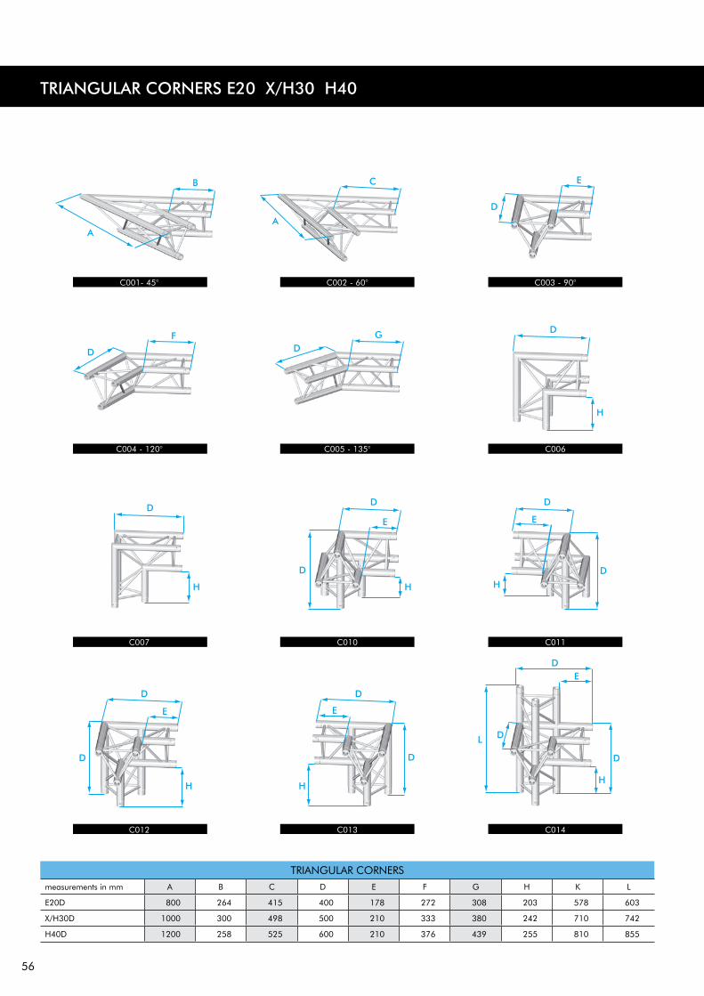
56
TRIANGULAR CORNERS E20 X/h30 h40
TRIANGULAR CORNERSmeasurements in mm A B C D E F G H K L
E20D 800 264 415 400 178 272 308 203 578 603
X/H30D 1000 300 498 500 210 333 380 242 710 742
H40D 1200 258 525 600 210 376 439 255 810 855
C001- 45° C002 - 60° C003 - 90°
C004 - 120° C005 - 135° C006
C007 C010 C011
C012 C013 C014

57
D
TRIANGULAR CORNERSmeasurements in mm A B C D E F G H K L
E20D 800 264 415 400 178 272 308 203 578 603
X/H30D 1000 300 498 500 210 333 380 242 710 742
H40D 1200 258 525 600 210 376 439 255 810 855
C015 C016 C017
C018 C019 C020
C021 C022 C023
C024

58
SQUARE CORNERS E20 X/h30 h40
SQUARE CORNERSmeasurements in mm A B C D E F G H
E20V 800 264 415 400 178 272 308 578
X/H30V 1000 300 498 500 210 333 380 710
H40V 1200 258 525 600 210 376 439 810
C001 - 45° C002 - 60° C003 - 90°
C004 - 120° C005 - 135° C012
C016 C017 C020
C022 C024

59
STANDARD CORNERS S36 SERIES
STANDARD CORNERS S36 SERIESmeasurements in mm A B C D E
S36R 475 125 600 429 172
S36V 475 125 600 429 172
S36R - C003 S36R - C007 S36R - C012
S36R - C013 S36R - C016 S36R - C017
S36V - C003 S36V - C012 S36V - C017
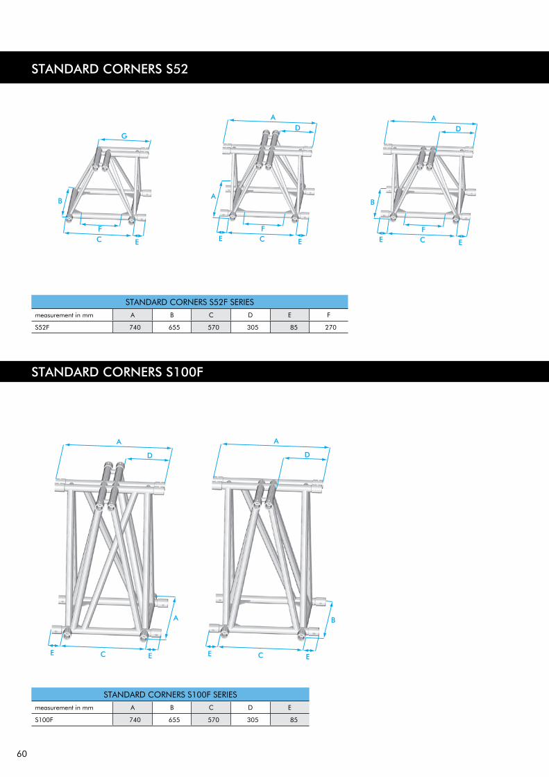
60
STANDARD CORNERS S52
STANDARD CORNERS S100F SERIESmeasurement in mm A B C D E
S100F 740 655 570 305 85
STANDARD CORNERS S52F SERIESmeasurement in mm A B C D E F
S52F 740 655 570 305 85 270
STANDARD CORNERS S100F

61
BOX CORNERS
BOX-20VBox-corner attachment, pre-assembled couplers.
BOX-20VAssembly.
BOX-20VBox corner for E20V truss. Measurements.
BOX-20LLadder box corner for E20 truss. Measurements.
TECHNICAL SPECIFICATIONS E20 BOX CORNERS
0-WAYKG LBS
2-WAYKG LBS
3-WAYKG LBS
4-WAYKG LBS
5-WAYKG LBS
6-WAYKG LBS
COUPLER BOLT SPRING WASHER
BOX-20V 3,7 8,2 4,2 9,3 4,7 10,4 5,2 11,5 5,7 12,6 6,2 13,7 CCS4-451 M8x25 M8
BOX-20L 3,7 8,2 4,2 9,3 4,7 10,4 5,2 11,5 CCS4-451 M8x25 M8
1 inch = 25.4 mm | 1m = 3.28 ft | 1 lbs = 0.453 kg | 1 daN = 10 N ~ 1 kg
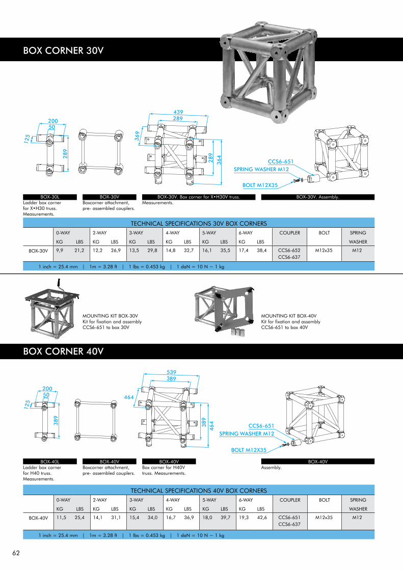
62
BOX CORNER 30V
BOX-30V. Box corner for X•H30V truss. Measurements.
BOX-30V. Assembly.BOX-30VBoxcorner attachment, pre- assembled couplers.
BOX-30L Ladder box corner for X•H30 truss.Measurements.
TECHNICAL SPECIFICATIONS 40V BOX CORNERS0-WAY 2-WAY 3-WAY 4-WAY 5-WAY 6-WAY COUPLER BOLT SPRING
KG LBS KG LBS KG LBS KG LBS KG LBS KG LBS WASHER
BOX-40V 11,5 25,4 14,1 31,1 15,4 34,0 16,7 36,9 18,0 39,7 19,3 42,6 CCS6-651CCS6-637
M12x35 M12
1 inch = 25.4 mm | 1m = 3.28 ft | 1 lbs = 0.453 kg | 1 daN = 10 N ~ 1 kg
TECHNICAL SPECIFICATIONS 30V BOX CORNERS0-WAY 2-WAY 3-WAY 4-WAY 5-WAY 6-WAY COUPLER BOLT SPRING
KG LBS KG LBS KG LBS KG LBS KG LBS KG LBS WASHER
BOX-30V 9,9 21,2 12,2 26,9 13,5 29,8 14,8 32,7 16,1 35,5 17,4 38,4 CCS6-652CCS6-637
M12x35 M12
1 inch = 25.4 mm | 1m = 3.28 ft | 1 lbs = 0.453 kg | 1 daN = 10 N ~ 1 kg
BOX-40VBox corner for H40V truss. Measurements.
BOX-40V Assembly.
BOX-40V Boxcorner attachment, pre- assembled couplers.
BOX-40L Ladder box corner for H40 truss. Measurements.
BOX CORNER 40V
MOUNTING KIT BOX-30VKit for fixation and assembly CCS6-651 to box 30V
MOUNTING KIT BOX-40VKit for fixation and assembly CCS6-651 to box 40V

63
BOX CORNERS S36
TECHNICAL SPECIFICATIONS S36 BOX CORNERS0-WAY 2-WAY 3-WAY 4-WAY 5-WAY 6-WAY COUPLER BOLT SPRING
KG LBS KG LBS KG LBS KG LBS KG LBS KG LBS WASHER
BOX-36R 15,9 35,1 17,7 39,1 19,5 43,0 21,2 46,8 23,0 50,8 24,8 54,7 CCS7-751 M16x35 M16
BOX-36V 21,0 46,4 22,8 50,3 24,5 54,1 26,3 58,1 28,1 62,0 29,9 66,0 CCS7-751 M16x35 M16
1 inch = 25.4 mm | 1m = 3.28 ft | 1 lbs = 0.453 kg | 1 daN = 10 N ~ 1 kg
BOX-36R. Assembly
BOX-36V. Assembly
BOX-36R. Box corner for S36R truss.
BOX-36V. Box corner for S36V truss.
ADAPTER S36RAlso available for Symmetrical setup with female couplers or A-symmetrical set-up with female couplers. Drawing available on request or on www.prolyte.com
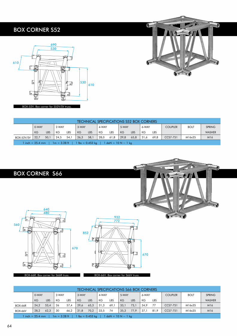
64
BOX CORNER S52
BOX CORNER S66
TECHNICAL SPECIFICATIONS S52 BOX CORNERS0-WAY 2-WAY 3-WAY 4-WAY 5-WAY 6-WAY COUPLER BOLT SPRING
KG LBS KG LBS KG LBS KG LBS KG LBS KG LBS WASHER
BOX-52V/SV 22,7 50,1 24,5 54,1 26,3 58,1 28,0 61,8 29,8 65,8 31,6 69,8 CCS7-751 M16x35 M16
1 inch = 25.4 mm | 1m = 3.28 ft | 1 lbs = 0.453 kg | 1 daN = 10 N ~ 1 kg
BOX-52V. Box corner for S52V/SV truss.
TECHNICAL SPECIFICATIONS S66 BOX CORNERS0-WAY 2-WAY 3-WAY 4-WAY 5-WAY 6-WAY COUPLER BOLT SPRING
KG LBS KG LBS KG LBS KG LBS KG LBS KG LBS WASHER
BOX-66R 24,2 53,4 26 57,4 29,6 65,3 31,3 69,1 33,1 73,1 34,9 77 CCS7-751 M16x35 M16
BOX-66V 28,2 62,3 30 66,2 31,8 70,2 33,5 74 35,3 77,9 37,1 81,9 CCS7-751 M16x35 M16
1 inch = 25.4 mm | 1m = 3.28 ft | 1 lbs = 0.453 kg | 1 daN = 10 N ~ 1 kg
BOX-66R. Box corner for S66R truss. BOX-66V. Box corner for S66V truss.
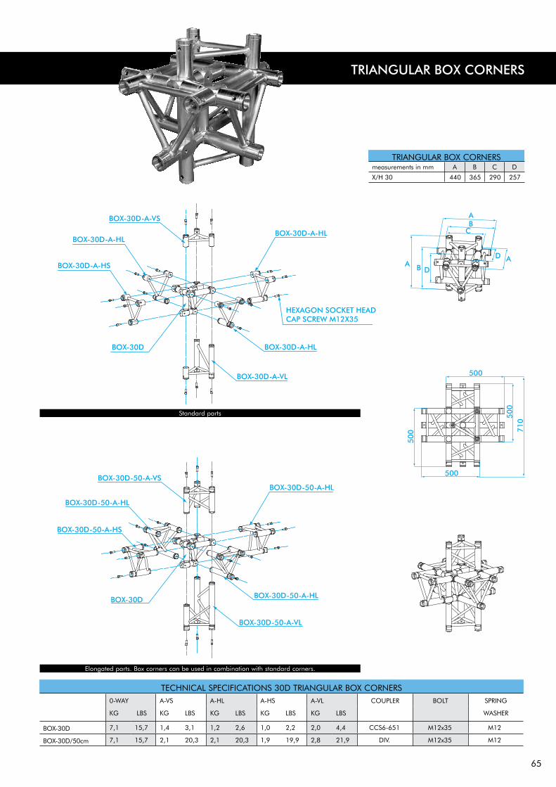
65
TECHNICAL SPECIFICATIONS 30D TRIANGULAR BOX CORNERS0-WAY A-VS A-HL A-HS A-VL COUPLER BOLT SPRING
KG LBS KG LBS KG LBS KG LBS KG LBS WASHER
BOX-30D 7,1 15,7 1,4 3,1 1,2 2,6 1,0 2,2 2,0 4,4 CCS6-651 M12x35 M12
BOX-30D/50cm 7,1 15,7 2,1 20,3 2,1 20,3 1,9 19,9 2,8 21,9 DIV. M12x35 M12
TRIANGULAR BOX CORNERSmeasurements in mm A B C D
X/H 30 440 365 290 257
TRIANGULAR BOX CORNERS
Assembly and part names.
Elongated parts. Box corners can be used in combination with standard corners.
Standard parts

66
BOOK CORNER 30D/V
TECHNICAL SPECIFICATIONS BOOK CORNERS 40D/VKG LBS MALE
COUPLERBOLT FEMALE
COUPLERBOLT NUT SPRING
WASHER
BOOK-40D/V 15,5 34,2 CCS6-602 M12x55 CCS6-651 M12x60 M12 M12
1 inch = 25.4 mm | 1m = 3.28 ft | 1 lbs = 0.453 kg | 1 daN = 10 N ~ 1 kg
BOOK CORNER 40D/V
TECHNICAL SPECIFICATIONS BOOK CORNERS 30D/VKG LBS MALE
COUPLERBOLT FEMALE
COUPLERBOLT NUT SPRING
WASHER
BOOK-30D/V 12,0 26,5 CCS6-602 M12x55 CCS6-651 M12x60 M12 M12
1 inch = 25.4 mm | 1m = 3.28 ft | 1 lbs = 0.453 kg | 1 daN = 10 N ~ 1 kg

67
BOOK CORNER 36R/V
BOOK CORNER 52F
TECHNICAL SPECIFICATIONS BOOK CORNERS 52F AND 52S/VKG LBS MALE
COUPLERBOLT FEMALE
COUPLERBOLT NUT SPRING
WASHER
BOOK-52F 21,5 47,5 CCS7-702 M16x60 CCS7-751 M16x60 M16 M16
BOOK-52S/SV 20,7 45,7 CCS7-702 M16x60 CCS7-751 M16x60 M16 M16
1 inch = 25.4 mm | 1m = 3.28 ft | 1 lbs = 0.453 kg | 1 daN = 10 N ~ 1 kg
TECHNICAL SPECIFICATIONS BOOK CORNERS 36R/VKG LBS MALE
COUPLERBOLT FEMALE
COUPLERBOLT NUT SPRING
WASHER
BOOK-36R 16,2 35,8 CCS7-702 M16x60 CCS7-751 M16x60 M16 M16
BOOK-36V 17,2 38,0 CCS7-702 M16x60 CCS7-751 M16x60 M16 M16
1 inch = 25.4 mm | 1m = 3.28 ft | 1 lbs = 0.453 kg | 1 daN = 10 N ~ 1 kg