decoupling phase-matching bandwidth and interaction ... · decoupling phase-matching bandwidth and...
TRANSCRIPT
Decoupling phase-matching bandwidth and interaction geometry using non-collinear quasi-phase-matching gratings
N. BIGLER,* J. PUPEIKIS, S. HRISAFOV, L. GALLMANN, C. R. PHILLIPS,AND U. KELLER
Department of Physics, Institute for Quantum Electronics, ETH Zurich, August-Piccard-Hof 1, 8093
Zurich, Switzerland
Abstract: In optical parametric amplification (OPA) of broadband pulses, a non-collinear
angle between the interacting waves is typically introduced in order to achieve broadband
phase-matching. Consequently, bandwidth and beam geometry are closely linked. This
coupling restricts the geometrical layout of an OPA system. Here, we demonstrate a quasi-
phase-matching (QPM) geometry for broadband OPA in which a transverse component is
introduced to the QPM grating to impose an additional momentum on the generated wave.
This momentum shift detunes the wavelength where the signal and the idler are group-
velocity matched, thereby allowing for broadband phase-matching without having to add a
non-collinear angle between the interacting waves. We present two experimental
configurations making use of this principle, and propose a third configuration with the
potential to further simplify ultra-broadband OPA system architectures.
© 2018 Optical Society of America under the terms of the OSA Open Access Publishing Agreement
OCIS codes: (190.4360) Nonlinear optics, devices; (190.7110) Ultrafast nonlinear optics; (190.4970) Parametric
oscillators and amplifiers.
References and links
1. U. Keller, “Recent developments in compact ultrafast lasers,” Nature 424(6950), 831–838 (2003).
2. T. Südmeyer, S. V. Marchese, S. Hashimoto, C. R. E. Baer, G. Gingras, B. Witzel, and U. Keller, “Femtosecond
laser oscillators for high-field science,” Nat. Photonics 2(10), 599–604 (2008).
3. S. Hädrich, J. Rothhardt, M. Krebs, S. Demmler, A. Klenke, A. Tünnermann, and J. Limpert, “Single-pass high
harmonic generation at high repetition rate and photon flux,” J. Phys. At. Mol. Opt. Phys. 49(17), 172002
(2016).
4. C. M. Heyl, J. Güdde, A. L’Huillier, and U. Höfer, “High-order harmonic generation with μJ laser pulses at high
repetition rates,” J. Phys. At. Mol. Opt. Phys. 45(7), 074020 (2012).
5. F. Emaury, A. Diebold, C. J. Saraceno, and U. Keller, “Compact extreme ultraviolet source at megahertz pulse
repetition rate with a low-noise ultrafast thin-disk laser oscillator,” Optica 2(11), 980–984 (2015).
6. M. Krebs, S. Hädrich, S. Demmler, J. Rothhardt, A. Zair, L. Chipperfield, J. Limpert, and A. Tünnermann,
“Towards isolated attosecond pulses at megahertz repetition rates,” Nat. Photonics 7(7), 555–559 (2013).
7. J. Rothhardt, S. Hädrich, Y. Shamir, M. Tschnernajew, R. Klas, A. Hoffmann, G. K. Tadesse, A. Klenke, T.
Gottschall, T. Eidam, J. Limpert, A. Tünnermann, R. Boll, C. Bomme, H. Dachraoui, B. Erk, M. Di Fraia, D. A.
Horke, T. Kierspel, T. Mullins, A. Przystawik, E. Savelyev, J. Wiese, T. Laarmann, J. Küpper, and D. Rolles,
“High-repetition-rate and high-photon-flux 70 eV high-harmonic source for coincidence ion imaging of gas-
phase molecules,” Opt. Express 24(16), 18133–18147 (2016).
8. S. M. Hooker, “Developments in laser-driven plasma accelerators,” Nat. Photonics 7(10), 775–782 (2013).
9. E. A. Peralta, K. Soong, R. J. England, E. R. Colby, Z. Wu, B. Montazeri, C. McGuinness, J. McNeur, K. J.
Leedle, D. Walz, E. B. Sozer, B. Cowan, B. Schwartz, G. Travish, and R. L. Byer, “Demonstration of electron
acceleration in a laser-driven dielectric microstructure,” Nature 503(7474), 91–94 (2013).
10. J. L. Krause, K. J. Schafer, and K. C. Kulander, “High-Order Harmonic generation from Atoms and Ions in the
High Intensity Regime,” Phys. Rev. Lett. 68(24), 3535–3538 (1992).
11. T. Popmintchev, M.-C. Chen, D. Popmintchev, P. Arpin, S. Brown, S. Ališauskas, G. Andriukaitis, T. Balčiunas,
O. D. Mücke, A. Pugzlys, A. Baltuška, B. Shim, S. E. Schrauth, A. Gaeta, C. Hernández-García, L. Plaja, A.
Becker, A. Jaron-Becker, M. M. Murnane, and H. C. Kapteyn, “Bright Coherent Ultrahigh Harmonics in the keV
x-ray Regime from Mid-Infrared Femtosecond Lasers,” Science 336(6086), 1287–1291 (2012).
12. S. Witte and K. S. E. Eikema, “Ultrafast Optical Parametric Chirped-Pulse Amplification,” IEEE J. Sel. Top.
Quantum Electron. 18(1), 296–307 (2012).
Vol. 26, No. 5 | 5 Mar 2018 | OPTICS EXPRESS 6036
#309537 https://doi.org/10.1364/OE.26.006036 Journal © 2018 Received 22 Nov 2017; revised 11 Jan 2018; accepted 26 Jan 2018; published 28 Feb 2018
13. P. Russbueldt, T. Mans, J. Weitenberg, H. D. Hoffmann, and R. Poprawe, “Compact diode-pumped 1.1 kW
Yb:YAG Innoslab femtosecond amplifier,” Opt. Lett. 35(24), 4169–4171 (2010).
14. J.-P. Negel, A. Voss, M. A. Ahmed, D. Bauer, D. Sutter, A. Killi, and T. Graf, “1.1 kW average output power
from a thin-disk multipass amplifier for ultrashort laser pulses,” Opt. Lett. 38(24), 5442–5445 (2013).
15. C. J. Saraceno, F. Emaury, C. Schriber, M. Hoffmann, M. Golling, T. Südmeyer, and U. Keller, “Ultrafast thin-
disk laser with 80 μJ pulse energy and 242 W of average power,” Opt. Lett. 39(1), 9–12 (2014).
16. T. Eidam, S. Hanf, E. Seise, T. V. Andersen, T. Gabler, C. Wirth, T. Schreiber, J. Limpert, and A. Tünnermann,
“Femtosecond fiber CPA system emitting 830 W average output power,” Opt. Lett. 35(2), 94–96 (2010).
17. A. Dubietis, R. Butkus, and A. P. Piskarskas, “Trends in Chirped Pulse Optical Parametric Amplification,” IEEE
J. Sel. Top. Quantum Electron. 12(2), 163–172 (2006).
18. T. Wilhelm, J. Piel, and E. Riedle, “Sub-20-fs pulses tunable across the visible from a blue-pumped single-pass
noncollinear parametric converter,” Opt. Lett. 22(19), 1494–1496 (1997).
19. B. W. Mayer, C. R. Phillips, L. Gallmann, and U. Keller, “Mid-infrared pulse generation via achromatic quasi-
phase-matched OPCPA,” Opt. Express 22(17), 20798–20808 (2014).
20. M. Hu, X. Liang, B. Zhao, R. Li, and Z. Xu, “Broad-Bandwidth Semi-Noncollinear Optical Parametric
Amplification in Periodically Poled LiNbO 3 Based on Tilted Quasi-Phase-Matched Gratings,” Jpn. J. Appl.
Phys. 46(8A), 5148–5152 (2007).
21. Y. Sasaki, A. Yuri, K. Kawase, and H. Ito, “Terahertz-wave surface-emitted difference frequency generation in
slant-stripe-type periodically poled LiNbO3 crystal,” Appl. Phys. Lett. 81(18), 3323–3325 (2002).
22. S. Ashihara, T. Shimura, and K. Kuroda, “Group-velocity matched second-harmonic generation in tilted quasi-
phase-matched gratings,” J. Opt. Soc. Am. B 20(5), 853–856 (2003).
23. A. M. Schober, M. Charbonneau-Lefort, and M. M. Fejer, “Broadband quasi-phase-matched second-harmonic
generation of ultrashort optical pulses with spectral angular dispersion,” J. Opt. Soc. Am. B 22(8), 1699–1713
(2005).
24. A. Shapira and A. Arie, “Phase-matched nonlinear diffraction,” Opt. Lett. 36(10), 1933–1935 (2011).
25. T. Ellenbogen, A. Arie, and S. M. Saltiel, “Noncollinear double quasi phase matching in one-dimensional poled
crystals,” Opt. Lett. 32(3), 262–264 (2007).
26. B. W. Mayer, C. R. Phillips, L. Gallmann, M. M. Fejer, and U. Keller, “Sub-four-cycle laser pulses directly from
a high-repetition-rate optical parametric chirped-pulse amplifier at 3.4 μm,” Opt. Lett. 38(21), 4265–4268
(2013).
27. C. R. Phillips, B. W. Mayer, L. Gallmann, and U. Keller, “Frequency-domain nonlinear optics in two-
dimensionally patterned quasi-phase-matching media,” Opt. Express 24(14), 15940–15953 (2016).
28. C. R. Phillips, A. S. Mayer, A. Klenner, and U. Keller, “Femtosecond mode locking based on adiabatic
excitation of quadratic solitons,” Optica 2(8), 667–674 (2015).
29. M. M. Fejer, G. A. Magel, D. H. Jundt, and R. L. Byer, “Quasi-phase-matched second harmonic generation:
tuning and tolerances,” IEEE J. Quantum Electron. 28(11), 2631–2654 (1992).
30. A. Shirakawa and T. Kobayashi, “Noncollinearly phase-matched femtosecond optical parametric amplification
with a 2000 cm1 bandwidth,” Appl. Phys. Lett. 72(2), 147–149 (1998).
31. G. Cerullo, M. Nisoli, S. Stagira, and S. De Silvestri, “Sub-8-fs pulses from an ultrabroadband optical parametric
amplifier in the visible,” Opt. Lett. 23(16), 1283–1285 (1998).
32. G. M. Gale, M. Cavallari, T. J. Driscoll, and F. Hache, “Sub-20-fs tunable pulses in the visible from an 82-MHz
optical parametric oscillator,” Opt. Lett. 20(14), 1562–1564 (1995).
1. Introduction
High-average-power ultrafast laser sources have received much attention over the last few
decades [1,2], and have enabled corresponding advances in science and industry. For
example, a broad range of intense light-matter interaction experiments have become possible
in the megahertz regime, such as the generation of extreme ultraviolet photons via high-
harmonic generation (HHG) [3–5], the generation of isolated attosecond pulses [6], the study
of strong-field ionization with coincidence detection [7], and laser-based particle acceleration
[8,9]. A significant direction in the field is the move towards longer wavelength sources, for
example to extend the HHG cut-off allowing for the generation of coherent soft-x-ray sources
[10,11]. Moreover, with conventional sources, the low repetition rates necessitate long
integration times. Hence there is a major effort to achieve broadband high repetition rate mid-
infrared laser systems.
Optical parametric chirped-pulse amplification (OPCPA) [12] is a compelling approach to
access the required parameters. In this technique, a narrow-band pump pulse is used to
amplify a broadband, temporally chirped signal pulse. Thus, it allows transferring the energy
of picosecond pump sources [13–16] to ultra-broadband few-cycle pulses, thereby benefiting
from the multi-100-W class picosecond industrial lasers which provide reliable, turn-key
Vol. 26, No. 5 | 5 Mar 2018 | OPTICS EXPRESS 6037
sources for demanding industrial applications such as cold-ablation microprocessing.
However, one of the main challenges of OPCPA is its complexity, leading to large and highly
sensitive systems comprised of multiple amplification stages.
A significant contributing factor to this complexity is the coupling between phase-
matching and beam geometry. For example, a common way to increase the amplification
bandwidth requires the use of a precise non-collinear angle between the pump and the signal
waves to reduce the group-velocity mismatch (GVM) between the idler and the signal wave
[17–19], thereby coupling the amplified bandwidth to the geometry of the interaction. Hu et
al. proposed a solution to reduce this complexity in the context of QPM [20]: adding a
transverse component to QPM gratings offers a new degree of freedom similar to that of the
pump-signal non-collinear angle, but without constraining the interaction geometry. Non-
collinear QPM gratings have been studied in the context of terahertz wave generation [21] as
well as broadband second harmonic generation [22,23], phase-matched nonlinear diffraction
[24] and cascaded up-conversion [25]. Moreover, since QPM devices are fabricated by
lithographic methods, a wide variety of two-dimensional patterns can be designed, enabling
functionalities not possible in homogeneous phase-matching media [26–28].
Here, we demonstrate the concept of broadband phase-matching with tilted QPM domains
in the context of OPA with two different amplification stages based on periodically poled
LiNbO3 (PPLN) devices. In both cases, we show that the addition of a transverse component
to the grating k-vector simplifies the experimental setup by decoupling broadband phase-
matching from the interaction geometry. Finally, we propose a new phase-matching geometry
for ultra-broadband amplification based on multiple consecutive amplification crystals and
enabled by such tilted QPM gratings.
2. QPM grating with a large transverse component
In three-wave mixing processes, the phase-matching condition Δk 0 needs to be fulfilled in
order to achieve an efficient transfer of energy between the interacting waves. In QPM [29],
the nonlinear coefficient of the medium is periodically (or aperiodically) inverted, leading to
an additional term Kg = 2π / Λg, for period Λg. The phase-matching condition then becomes
0,p s i gk k k k K (1)
where kp, ks and ki are the pump, signal and idler wave vectors respectively, with ωp > ωs > ωi
and the pump is the narrowband wave. In the general case of arbitrary angles of the
interacting waves and the QPM grating k-vector (Fig. 1(a)), we can derive a relation for
broadband phase-matching as follows. First, Eq. (1) can be projected onto the longitudinal
axis z and the transverse axis x
,cos ( ) ( )c( ) os( 0) ,p p s s i i i g zk k k K (2)
,sin( ) ( )sin( ) 0,p i i i gp xk k K (3)
with the angles θp and θi as defined in Fig. 1(a). Solving Eq. (3) for θi we obtain
,1sin( )
(n
)si .
p p g x
i
i i
k K
k
(4)
This relation describes the output angle of the generated idler. Its dependence on the
frequency term ωi leads to an angular chirp when the numerator is non-zero, as depicted in
Fig. 1(c). Furthermore, the mean output angle is directly dependent on both the pump non-
collinear angle as well as the transverse grating component Kg,x.
Vol. 26, No. 5 | 5 Mar 2018 | OPTICS EXPRESS 6038

One way to achieve a broadband amplification is to operate close to the point where the
slope of the Δk curve is close to 0, i.e. when Δk / ω = 0. Considering the pump beam being
single frequency and taking the derivative of Eqs. (2) and (3) we obtain
) sin( )
) cos(
cos( 0,
sin( 0.)
s i i
i i i
i i
i i i
k k
kk
k
(5)
After further mathematical manipulation, this leads to
, , )c ,os(g s g i i (6)
where νg,s = (ks / ω)1 and νg,i = (ki / ω)1 are the group-velocities of signal and idler,
respectively. In other words, a broad bandwidth will be phase-matched when the projection of
the group-velocity of the idler along the signal direction is equal to that of the signal, i.e.
when the GVM between the signal and the idler is minimized. This property is widely
exploited in broadband non-collinear OPA [18,19,30–32]. Here we demonstrate how a non-
collinear QPM can be introduced in place of, or in addition to a non-collinear angle, to obtain
the required group-velocity matching condition while keeping a flexible interaction geometry.
Fig. 1. a) A three-wave mixing interaction in QPM with arbitrary angles. b) A microscope
image of a tilted QPM grating used in one of our experiments (Kg,x = 1138 mm1 and Kg,z = 161
mm1). c) The wave vectors diagram for a specific OPA interaction, where the pump and
signal are collinear, while a large transverse component was added to the QPM grating. d) The
calculated phase-mismatch curves for the interaction geometry shown in c) and for different
transverse grating components Kg,x. The longitudinal grating component Kg,z was tuned to keep
the minimum of the curves close to 0 mm1. The turning point of the curve is pushed towards
longer wavelengths for large Kg,x
As shown in Eqs. (4) and (6), we can tune the idler group velocity projection to match the
signal group velocity by changing either the pump angle θp or the transverse grating
Vol. 26, No. 5 | 5 Mar 2018 | OPTICS EXPRESS 6039
component Kg,x. Adding a transverse component to the QPM grating therefore offers a new
degree of freedom to select the point of group-velocity matching, allowing decoupling the
geometry of the interaction from the phase-matched bandwidth. A microscopic image of such
a grating, as used in one of our experiments, is shown in Fig. 1(b).
As an example, we follow the geometry given in Fig. 1(c) where both the signal and the
pump are collinear but the QPM grating displays a large transverse component. Figure 1(d)
shows the evolution of the phase-matching curve when increasing the transverse grating
component Kg,x while tuning the longitudinal grating component Kg,z to keep the minimum of
the curve at a constant Δk. As follows from Eqs. (4) and (6), the idler output angle θi increases
with increasing Kg,x, pushing the point where the GVM is minimized towards longer
wavelengths.
3. Experiments
In Section 3.1, we present the mid-IR OPCPA system used in our experiments. Then, we
discuss a first experiment making use of a non-collinear QPM grating with collinear pump
and signal (Section 3.2) before moving on to a second experiment with both a non-collinear
pump and a non-collinear grating (Section 3.3).
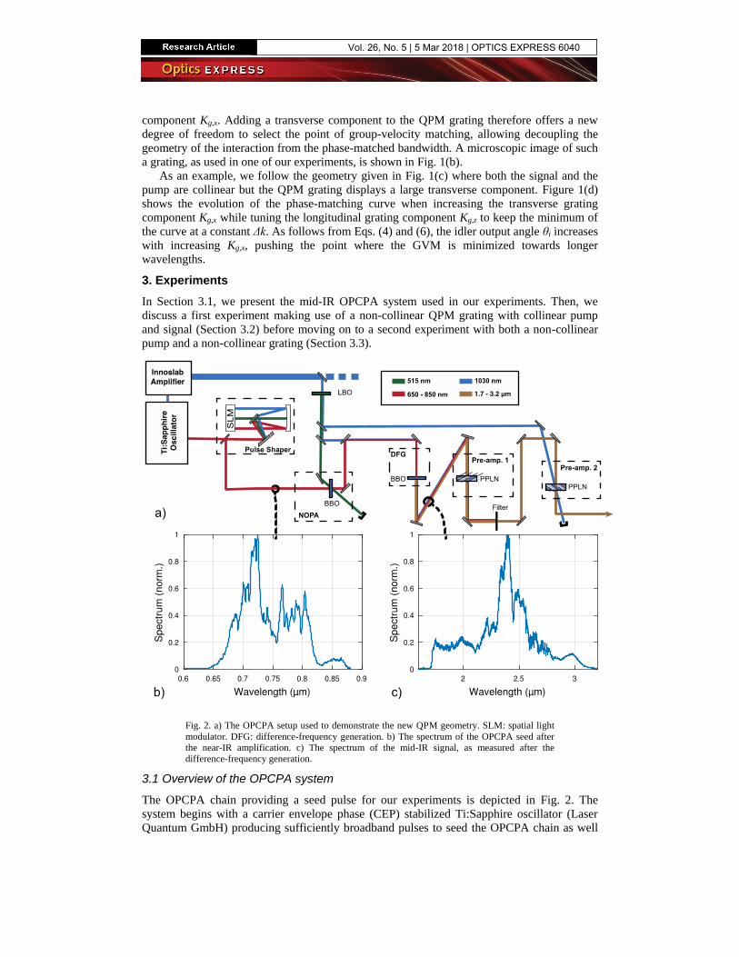
Fig. 2. a) The OPCPA setup used to demonstrate the new QPM geometry. SLM: spatial light
modulator. DFG: difference-frequency generation. b) The spectrum of the OPCPA seed after
the near-IR amplification. c) The spectrum of the mid-IR signal, as measured after the
difference-frequency generation.
3.1 Overview of the OPCPA system
The OPCPA chain providing a seed pulse for our experiments is depicted in Fig. 2. The
system begins with a carrier envelope phase (CEP) stabilized Ti:Sapphire oscillator (Laser
Quantum GmbH) producing sufficiently broadband pulses to seed the OPCPA chain as well
Vol. 26, No. 5 | 5 Mar 2018 | OPTICS EXPRESS 6040

as the pump laser amplification chain. A portion of the corresponding spectrum around
1030 nm is pre-amplified and pulse picked to 100 kHz, before being sent towards a high-
power Yb:YAG Innoslab amplifier (Amphos GmbH) [8], which produces 300 W average
power after compression, with a pulse duration < 3 ps. The OPCPA seed (650-850 nm) is first
directed to a 4-f pulse shaper and then to the first parametric amplification stage.
We use 40 W of the available pump power for the pre-amplification system, which
includes the two QPM devices discussed here. This system begins with a second harmonic
generation stage producing 17.8 W of 515 nm light. This light is then used to pump a 1.8-
mm-long BBO crystal in a non-collinear configuration, amplifying the 0.2 nJ near-IR signal
pulses to 1.9 µJ with the spectrum displayed in Fig. 2(b). The amplified signal is then
overlapped collinearly in a difference-frequency generation (DFG) stage (BBO, 0.3-mm-
long) with 2.9 W of 1030 nm pump. We obtain 1.2 mW of mid-IR light with the spectrum
shown in Fig. 2(c). The spectra of the MIR pulses were measured with an acousto-optic
modulator-based scanning MIR spectrometer (MOZZA, Fastlite).
3.2 Separation of a collinear and degenerate idler
It is necessary to use a collinear geometry in the DFG stage in order to ensure a mid-IR signal
beam free of angular chirp. However, this also makes it impossible to immediately follow the
DFG stage with a first pre-amplification stage. The idler generated in the pre-amplification
stage would be overlapped spatially (collinear geometry) as well as spectrally (operating near
degeneracy) and in polarization (use of the large d33 nonlinear coefficient in the PPLN
crystal) with the amplified signal. Since it would have an opposite temporal chirp, this would
lead to unwanted spectral interference.
Rather than splitting the signal and pump beams, which would entail a more complex
setup, we use the QPM grating to impose a transverse momentum onto the idler to make it
spatially separable from the amplified signal beam, as described in Eq. (4). This results in a
very simple and compact setup.
Fig. 3. a) The amplified spectrum after the first preamplifier. We amplify the whole spectrum
and reach an average gain of 13 dB. b) The measured output beam profiles. The idler is
separated from the signal and displays a spatial chirp, as expected from Eq. (4). The calculated
idler spectrum is superimposed in white.
Our implementation of this method relies on a PPLN crystal with Kg,z = 210 mm1 and
Kg,x = 250 mm1 (poling period of 19.2 µm) and a length of 1.5 mm. All the PPLN crystals
used in this study were obtained from Gooch & Housego PLC. The pump power inside the
uncoated crystal is 2 W and it is focused to reach an intensity of 24 GW/cm2. Figure 3(a)
shows the measured spectrum after amplification. The seed bandwidth is preserved and the
Vol. 26, No. 5 | 5 Mar 2018 | OPTICS EXPRESS 6041
signal energy after amplification is 240 nJ, corresponding to a gain of 13 dB. The output
beams were collimated after the QPM crystal and directed towards a pyroelectric camera
(Pyrocam III, Ophir Optronics Solutions Ltd). Figure 3(b) shows the measured beam profile,
demonstrating the separation between the signal and the idler. Furthermore, the idler exhibits
a spatial chirp, which arises from the angular chirp as described by Eq. (4). The two visible
peaks emerge from the structure of the calculated idler spectrum (superimposed in white).
3.3 Tuning of the group-velocity matching
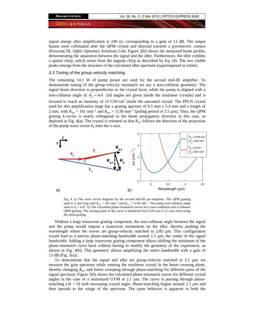
The remaining 14.1 W of pump power are used for the second mid-IR amplifier. To
demonstrate tuning of the group-velocity mismatch we use a non-collinear geometry. The
signal beam direction is perpendicular to the crystal facet, while the pump is aligned with a
non-collinear angle of 4.4p (all angles are given inside the nonlinear crystals) and is
focused to reach an intensity of 13 GW/cm2 inside the uncoated crystal. The PPLN crystal
used for this amplification stage has a grating aperture of 0.5 mm x 5.4 mm and a length of
2 mm, with Kg,z = 161 mm1 and Kg,x = 1138 mm1 (poling period of 5.5 µm). Thus, the QPM
grating k-vector is nearly orthogonal to the beam propagation direction in this case, as
depicted in Fig. 4(a). The crystal is oriented so that Kg,x follows the direction of the projection
of the pump wave vector kp onto the x-axis.
Fig. 4. a) The wave vector diagram for the second mid-IR pre-amplifier. The QPM grating
used is 2 mm long with Kg,z = 161 mm1 and Kg,x = 1138 mm1. The pump non-collinear angle
used is θp = 4.4°. b) The calculated phase-mismatch curves for a non-conllinear and a collinear
QPM grating. The turning point of the curve is displaced from 2.85 µm to 2.1 µm when using
the tilted grating.
Without a large transverse grating component, the non-collinear angle between the signal
and the pump would impose a transverse momentum on the idler, thereby pushing the
wavelength where the waves are group-velocity matched to 2.85 µm. This configuration
would lead to a narrow phase-matching bandwidth around 2.1 µm, the center of the signal
bandwidth. Adding a large transverse grating component allows shifting the minimum of the
phase-mismatch curve back without having to modify the geometry of the experiment, as
shown in Fig. 4(b). This geometry allows amplifying the entire bandwidth with a gain of
13 dB (Fig. 5(a)).
To demonstrate that the signal and idler are group-velocity matched at 2.1 µm, we
measure the gain spectrum while rotating the nonlinear crystal in the beam crossing plane,
thereby changing Kg,z and hence sweeping through phase-matching for different parts of the
signal spectrum. Figure 5(b) shows the calculated phase-mismatch curves for different crystal
angles in the case of a minimized GVM at 2.1 µm. The curve is passing through phase-
matching (Δk = 0) with increasing crystal angle. Phase-matching begins around 2.1 µm and
then spreads to the wings of the spectrum. The same behavior is apparent in both the
Vol. 26, No. 5 | 5 Mar 2018 | OPTICS EXPRESS 6042
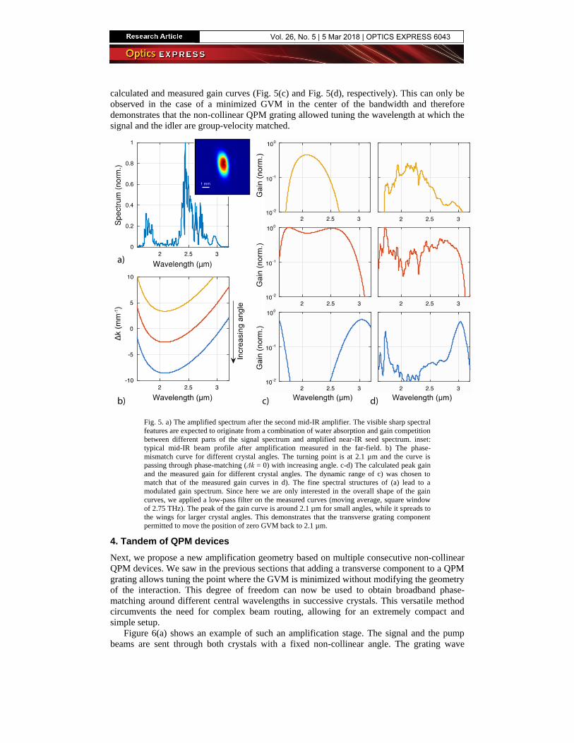
calculated and measured gain curves (Fig. 5(c) and Fig. 5(d), respectively). This can only be
observed in the case of a minimized GVM in the center of the bandwidth and therefore
demonstrates that the non-collinear QPM grating allowed tuning the wavelength at which the
signal and the idler are group-velocity matched.
Fig. 5. a) The amplified spectrum after the second mid-IR amplifier. The visible sharp spectral
features are expected to originate from a combination of water absorption and gain competition
between different parts of the signal spectrum and amplified near-IR seed spectrum. inset:
typical mid-IR beam profile after amplification measured in the far-field. b) The phase-
mismatch curve for different crystal angles. The turning point is at 2.1 µm and the curve is
passing through phase-matching (Δk = 0) with increasing angle. c-d) The calculated peak gain
and the measured gain for different crystal angles. The dynamic range of c) was chosen to
match that of the measured gain curves in d). The fine spectral structures of (a) lead to a
modulated gain spectrum. Since here we are only interested in the overall shape of the gain
curves, we applied a low-pass filter on the measured curves (moving average, square window
of 2.75 THz). The peak of the gain curve is around 2.1 µm for small angles, while it spreads to
the wings for larger crystal angles. This demonstrates that the transverse grating component
permitted to move the position of zero GVM back to 2.1 µm.
4. Tandem of QPM devices
Next, we propose a new amplification geometry based on multiple consecutive non-collinear
QPM devices. We saw in the previous sections that adding a transverse component to a QPM
grating allows tuning the point where the GVM is minimized without modifying the geometry
of the interaction. This degree of freedom can now be used to obtain broadband phase-
matching around different central wavelengths in successive crystals. This versatile method
circumvents the need for complex beam routing, allowing for an extremely compact and
simple setup.
Figure 6(a) shows an example of such an amplification stage. The signal and the pump
beams are sent through both crystals with a fixed non-collinear angle. The grating wave
Vol. 26, No. 5 | 5 Mar 2018 | OPTICS EXPRESS 6043
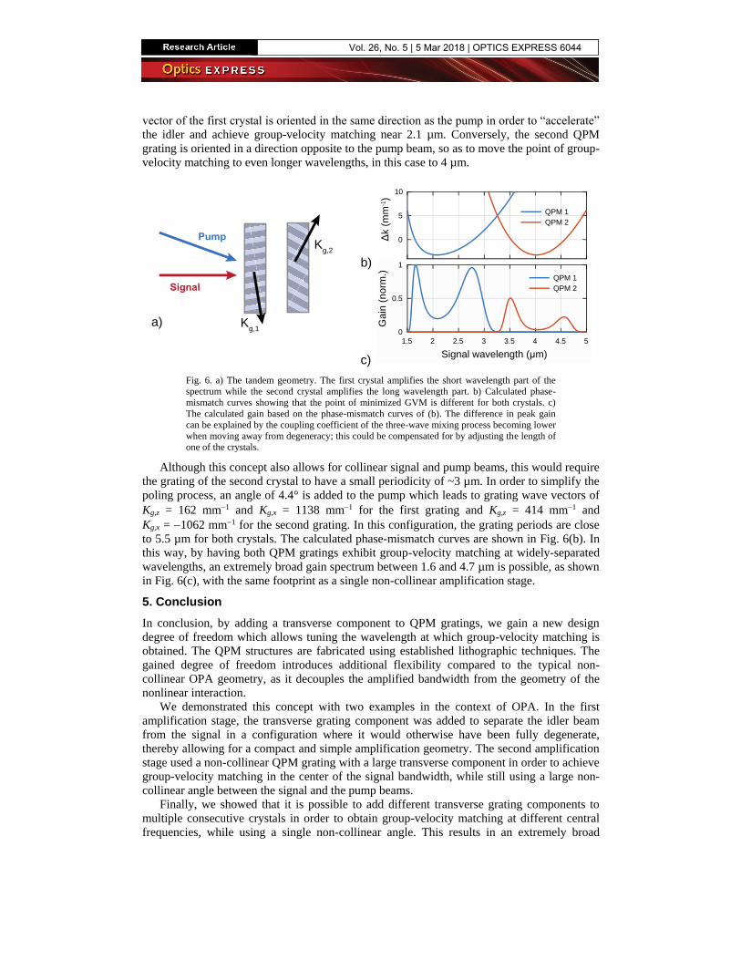
vector of the first crystal is oriented in the same direction as the pump in order to “accelerate”
the idler and achieve group-velocity matching near 2.1 µm. Conversely, the second QPM
grating is oriented in a direction opposite to the pump beam, so as to move the point of group-
velocity matching to even longer wavelengths, in this case to 4 µm.
0
5
10
Δk (
mm
-1)
QPM 1
QPM 2
b)
a)
c)
1.5 2 2.5 3 3.5 4 4.5 5
Signal wavelength (µm)
0
0.5
1
Ga
in (
no
rm.)
QPM 1
QPM 2
Pump
Signal
Kg,1
Kg,2
Fig. 6. a) The tandem geometry. The first crystal amplifies the short wavelength part of the
spectrum while the second crystal amplifies the long wavelength part. b) Calculated phase-
mismatch curves showing that the point of minimized GVM is different for both crystals. c)
The calculated gain based on the phase-mismatch curves of (b). The difference in peak gain
can be explained by the coupling coefficient of the three-wave mixing process becoming lower
when moving away from degeneracy; this could be compensated for by adjusting the length of
one of the crystals.
Although this concept also allows for collinear signal and pump beams, this would require
the grating of the second crystal to have a small periodicity of ~3 µm. In order to simplify the
poling process, an angle of 4.4° is added to the pump which leads to grating wave vectors of
Kg,z = 162 mm1 and Kg,x = 1138 mm1 for the first grating and Kg,z = 414 mm1 and
Kg,x = 1062 mm1 for the second grating. In this configuration, the grating periods are close
to 5.5 µm for both crystals. The calculated phase-mismatch curves are shown in Fig. 6(b). In
this way, by having both QPM gratings exhibit group-velocity matching at widely-separated
wavelengths, an extremely broad gain spectrum between 1.6 and 4.7 µm is possible, as shown
in Fig. 6(c), with the same footprint as a single non-collinear amplification stage.
5. Conclusion
In conclusion, by adding a transverse component to QPM gratings, we gain a new design
degree of freedom which allows tuning the wavelength at which group-velocity matching is
obtained. The QPM structures are fabricated using established lithographic techniques. The
gained degree of freedom introduces additional flexibility compared to the typical non-
collinear OPA geometry, as it decouples the amplified bandwidth from the geometry of the
nonlinear interaction.
We demonstrated this concept with two examples in the context of OPA. In the first
amplification stage, the transverse grating component was added to separate the idler beam
from the signal in a configuration where it would otherwise have been fully degenerate,
thereby allowing for a compact and simple amplification geometry. The second amplification
stage used a non-collinear QPM grating with a large transverse component in order to achieve
group-velocity matching in the center of the signal bandwidth, while still using a large non-
collinear angle between the signal and the pump beams.
Finally, we showed that it is possible to add different transverse grating components to
multiple consecutive crystals in order to obtain group-velocity matching at different central
frequencies, while using a single non-collinear angle. This results in an extremely broad
Vol. 26, No. 5 | 5 Mar 2018 | OPTICS EXPRESS 6044
amplification bandwidth, potentially spanning multiple octaves, while bypassing the need to
separate and recombine beams at specific non-collinear angles between crystals. This last
example demonstrates the versatility offered by tilted QPM devices, as well as the
improvement obtained by the decoupling of phase-matching and nonlinear interaction
geometry. We expect that tilted QPM structures will have a broad impact especially in the
context of OPCPA, where they could simplify both designs and implementations of otherwise
complex setups.
Funding
Swiss National Science Foundation (SNSF) (159975, 172644).
Vol. 26, No. 5 | 5 Mar 2018 | OPTICS EXPRESS 6045