decscope users' manual - mirror service
TRANSCRIPT

~D~DDmD
DECscope Users' Manual

DECscope User's Manual EK-VT5X-OP-001
This manual is for the owners and operators of the DECscope (VT50) family of video terminals, and for those who will be programming computers to interact with the terminals.
VT52
VT50H
VT50
The 24-line, upper-and-Iower-case video terminal.
The 12-line, upper-ease-only terminal with numeric pad.
The 12-line, upper-ease-only terminal without numeric pad.
For the operation, programming, and maintenance of the integral electrolytic copier, found on the VT50J and VT52B options, consult the Copier Users' Manual, EK-VT5C-OP. The description of the VT52 in the manual you are reading now is valid to describe the VT52 with or without copier. Where those two models differ, this manual distinguishes between them.
Users of the VT55 video terminal with graphics can use this manual as a reference guide to all the features of the VT55 except the graphics capabilities, by referring to the parts of this manual which describe the VT50. The graphics features of the VT55 are not described in this manual.
iii

Copyright © 1975 by Digital Equipment Corporation
All rights reserved
The material in this manual is for informational purposes and is subject to change without notice.
Digital Equipment Corporation assumes no respon
sibility for any errors which may appear in this
manual.
Printed in U.S.A.
The following are trademarks of Digital Equipment
Corporation, Maynard, Massachusetts:
DEC DECCOMM DECsystem-10 DECSYSTEM-20
DECtape DECUS DIGITAL MASSBUS
7/77-14
PDP RSTS TYPESET-8 TYPESET-11 UNIBUS
1 st Edition, April 1976 2nd Printing, June 1976 3rd Printing, July 1976 4th Printing, March 1977

TABLE OF CONTENTS
FOR OWNERS. . . . . . . . . . . . . . . . . . . . . • . . . . . . . . . . . . . . . . . . . . . . . . . . . . . . . . . . . . .. 1 Preparing the Environment for the DECscope . . . . . . . . . . . . . . . . . . . . . . . . .. 2 Installing the DECscope and Interfacing to a Computer . . . . . . . . . . . . . . . . . .. 2 I rregularities in the Appearance of the Screen. . . . . . . . . . . . . . . . . . . . . . . . .. 3 User Maintenance. . . . . . . . . . . . . . . . . . . . . . . . . . . . . . . . . . . . . . . . . . .. 3 DEC Maintenance Arrangements .................................. 3
FOR OPE RATORS . . . . . . . . . . . . . . . . . . . . . . . . . . . . . . . . . . . . . . . . . . . . . . . . . . . . . . . .. 4
FOR PROGRAMMERS. . . . . . . . . . . . . . . . . . . . . . . . . . . . . . . . . . . . . . . . . . . . . . . . . . . . .. 8
SECTION 1
SECTION 2
SECTION 3
APPENDIX A
APPENDIX B
OVERVIEW ................................................ 9 An I nput Device . . . . . . . . . . . . . . . . . . . . . . . . . . . . . . . . . . . . . . . . . . . .. 9 An Output Device. . . . . . . . . . . . . . . . . . . . . . . . . . . . . . . . . . . . . . . . . . .. 9 Serial Encoding: Parity and Stop Bits ............................... 10
THE KEYBOARD ............................................ 11 The Alphabetic Keys .......................................... 11 Non-alphabetic Keys Common to all Terminals ......................... 12 Non-alphabetic Keys Which Are Different on Different Models .............. 12 Function Keys .............................................. 12 The CTR L (Control) Key ....................................... 13 SCROLL and COpy Keys ............ ; .......................... 14 The BREAK Key ............................................. 14 The Auxiliary Keypad ......................................... 14 The REPEAT Key ............................................ 15
THE COMMANDS ............................................ 16 Displayable Characters ......................................... 16 Control Codes. . . . . . . . . . ..................................... 16 Filler Characters ............................................. 17 Synchronization ............................................. 17 Basic Cursor Movement Commands ................................. 19 Advanced Cursor Movement Commands ............................. 20 Screen Erasure Commands ...................................... 21 Audible Signals .............................................. 22 Distinguishing Different Models ................................... 22 Hold-Screen Mode ............................................ 23 Alternate-Keypad Mode ........................................ 24 Graphics Mode .............................................. 24
THE BAUD-RATE SWITCHES ................................... 26
DISPLAY OF THE CODES 136-176 ................................ 28
SUMMARY OF SPECIFICATIONS .............................................. 30
iv


For Owners This part of the DECscope Users' Manual contains information helpful in planning for, installing, and maintaining the DECscope.
1

PREPARING THE ENVIRONMENT FOR THE DECSCOPE
The design of the DECscope will normally pose few constraints on the selection of a place to install the terminal. In most cases, any environment which is suitable to the operator of the terminal will be a satisfactory environment in which to operate the terminal. Extremes of temperature and humidity should be avoided. A summary of the guaranteed operating conditions of the DECscope is found at the end of the manual.
Like many video terminals and televisions, the DECscope's picture-tube electronics emit a high-pitched frequency. Many older persons cannot even hear this whine. Nevertheless, it may be advisable to provide background noise in the operating environment of the terminal, if it is being operated by persons who could experience discomfort from hearing this tone for long periods of time.
INSTALLING THE DECSCOPE AND INTERFACING TO A COMPUTER
Take the following steps to set up the DECscope:
1. Unpack the unit and place it on the desk or surface where it will be operated.
2. Notice the blue and silver tag at the rear of the unit. As well as containing the serial number of the unit, this tag indicates the exact model number. It should contain one of the following labels:
VT50 Ax (or Cx)
VT50 Hx
VT50 Jx
VT52 Ax (or Cx)
VT52 Bx
The terminal this manual refers to as the "VT50".
The terminal referred to as the "VT50H".
The "VT50H" with copier. Read the Copier Users' Manual, which is also shipped with the unit, for further information.
The terminal referred to as the "VT52".
The "VT52" with copier; again, read the Copier Users' Manual for more information.
3. The voltage and power requirements of the terminal are listed on the On/Off Switch Plate on the side of the terminal. Some terminals can operate at two nominal voltages. These terminals will have reversible switch plates. Unscrewing and reversing the switch plates will allow the switch to be moved to an alternate ON position suitable for this second voltage level.
\ Plug the three-pronged line cord of the unit into an electrical outlet that meets the requirements of the terminal.
4. TO SET THE TERMINAL UP FOR THE OPERATOR EXPERIMENTS DESCRIBED IN THIS MANUAL: Tip the unit up on its rear. Notice the two rotary switches. These are the Baud rate switches. To set the terminal for off-line operation, in which the operator may type directly to the screen instead of to a computer, use a screwdriver or coin to turn S1 (the one on the right) to its most counterclockwise position, Position 1. Turn the other switch, S2, to its most clockwise position, and then counterclockwise one position. This is Position G. The terminal is now set up to be used as described in the "FOR OPERATORS" portion of this manual.
5. There is another cable coming from the bottom of the unit. This cable will have a Mate-'nLok® connector, an EIA connector, or a telephone-type plug, depending on which option you ordered. (On the VT50 and VT50H, an EIA connector can be attached to one of the printed circuit boards. This connector kit will contain installation instructions.) Plug this connector into the input/output port of the computer with which you wish to communicate.
6. Now set the Baud rate switches on the underside of the unit. Refer to Appendix A to determine in which position to set the switches; also, notice the label on the underside of the unit. The transmitting speed of the DECscope must match the receiving speed of the computer; the receiving speed of the DECscope must match the transmitting speed of the computer.
2

IRREGULARITIES IN THE APPEARANCE OF THE SCREEN
At some time in its life, the picture tube may appear to darken at each character position. This is a normal phenomenon; it does not affect the life expectancy of the tube and will not interfere with the display of characters when the DECscope is in operation. It is caused by the fact that the terminal lights up the screen only at the character positions, "breaking in" the phosphor at those positions on the screen.
Not all DECscopes contain the same type of picture tube. For this reason, the color of the screen may not be the same from unit to unit.
If, for these or other reasons, the appearance of the screen is not satisfactory, colored filters may be attached to the screen. A special nib was designed at the base of the screen in order to hold such filters in place.
USER MAINTENANCE
The keyboard and key-click mechanism are the only moving parts of the terminal and require no preventive maintenance by the owner. The DECscope may be cleaned with soap and water or any mild detergent. Although the terminal's shell provides superior resistance to damage from solvents, cleaners with solvents should not be used.
The DECscope packaging is not meant to be weatherproof; there are also several openings in the case through which liquids, coins, paper clips, and other objects can fall. Such objects would disturb the electronic operation of the terminal if they came in contact with the circuitry. For this reason, avoid putting drinks and metal objects on the top of the terminal, or using excessive water to clean the terminal. The keyboard area is an area where the electronics are particularly close to the exterior. Rubbing the keys with a dry or barely moist cloth should suffice to clean them. Do not remove the keycaps to clean them more thoroughly; damage may result to the switch contacts if they are replaced incorrectly.
DEC MAINTENANCE ARRANGEMENTS
There are four ways that the owner can arrange for service on a DECscope:
1. Depot Maintenance. Service will be done at the DEC depot. You buy a mailer, pack the VT50 in it, and return it to the Depot. Upon completion of service, Digital returns the unit.
2. On-Site Contract. This is the traditional priority service contract, available with various coverage hours.
3. On-Site, Per-Call Service. In this arrangement, Digital charages for time and materials actually used.
4. On-Site User Maintenance. Module-Swapping Kits are available. Failed modules are returned to the DEC Depot for repair in the mailers in which the swapping kits are mailed.
In some geographical areas, additional options are available; contact your local Digital Field Service office for information.
For customers who wish to do their own maintenance, Digital provides the DECscope System Manual, which explains the theory of operation and general troubleshooting procedures and includes prints and microprogram listings.
3

For Operators This part of the Users' Manual is a collection ofexperhnents designed to familiarize you with the DECscope. In addition, by performing these experiments, you can make sure the terminal works correctly.
In order to ensure that the experiments are successful, the terminal should be switched OFF-LINE.
4

The DECscope is a machine that lets you talk to a computer. It looks like a combination of a typewriter and a television. You talk to the computer by typing on the keyboard, and the computer talks to you by making messages visible on the screen. When you type things to the computer, the computer will usually put what you typed up on the screen so that you can see what you are typing.
In these experiments, your terminal has been switched OFF-LINE. Instead of the keyboard sending to the computer and the computer sending to the screen, the keyboard will send directly to the screen. You will be using the DECscope in the future to talk to a computer - but you are not talking to it now. Therefore, these experiments will teach you how to use the temrinal, but they will not teach you what kinds of things you should say to the computer when the terminal is connected to the computer. That you must discuss with the people who program the computer to act the way it does.
If this is your first experience with a video terminal like the DECscope, don't be alarmed at the strange keys on the keyboard. There is no way that you can damage the terminal by simply typing those keys. Some of the keys may produce confusing results when you type them, but this book is here to make them unconfusing.
Experiment 1. Locate the ON/OFF switch. If you are sitting in front of the terminal, look to your right at the side of the terminal. The switch that you see is the ON/OFF switch. Switch it to the ON position - a label around the switch will tell you which position that is. (If the terminal is already on, switch it OFF and ON again.)
Experiment 2. Give the TV tube about a half a minute to warm up. Then look at the upper left corner of the screen. You should see a flashing line. This line is called the cursor. If you cannot see the cursor, or if it is brighter than you want it, there is a lever at the back of the terminal which will control the general brightness of everything on the screen. If you'd like to change the intensity of the cursor, get up and move the lever until the cursor is at the right intensity. (This is the only adjustment you will have to make. If you don't see the cursor no matter how you move the intensity lever, then something is wrong. The terminal may not be plugged in, or it may not really be switched ON, or the circuit breaker may have blown.)
Experiment 3. Type a letter on the keyboard, and look at the screen where you saw the cursor. You should see that letter. The terminal displayed it directly above where the cursor was, and then it moved the cursor to the right, so that the next character you type will go there. Type another letter and you will see that it appears on the screen directly to the right of the first letter, and that the cursor moves over again. This is what the cursor does - it tells you exactly where you are as you type.
Notice that each time you typed a key, the terminal made a clicking sound. This is its way of telling you that it got the message.
Experiment 4. Continue typing letters and watch them appear on the screen. When you have typed 72 letters, the terminal will ring a buzzer if it is a VT50 or VT50H. This is to warn you that you are getting close to the right margin of the line - there is only room for 80 characters on each line. (The VT52 does not ring its buzzer when it reaches column 72.)
Keep typing. After typing eight more characters, you should reach the end ofthe line. Look at the cursorit is under the letter you just typed because it could not move any further to the right.
Experiment 5. Type another letter. The cursor cannot move anywhere since it is at the end of the line. But the letter you just typed replaces the one that was over the cursor. If you type another letter, that letter will replace what is there now. Type several letters, with the cursor still at the end of the line, and see that each letter replaces what was there before.
This is an important part of how the terminal works. Only one letter can occupy each place on the screen at any time. At the upper right of the keyboard, there is a blue key labeled BACKSPACE. If you type it, the cursor will move backward, or to the left. It will move left one column for each time you type the key. Using the BACK SPACE key, move the cursor back to the middle of the line. Now, type some more letters, and see that the letters you are typing are replacing what used to be on the screen.
Closest to you on the keyboard is the blue Space bar. This works exactly like the Space bar on a typewriter. Normally, it will move the cursor one column to the right. But it puts a Space on the screen, just as the letter keys put letters on the screen. Use the Space bar to replace some of the line you typed in with spaces. This is one way to erase information on the screen.
5

Experiment 6. Near your right hand is a large, blue key labeled RETURN. If you type this key, the cursor should move to the left margin of the line it is on. Tryout the RETURN key, and verify that the cursor moves to the beginning of the line.
Above the RETURN key is the LINE FEED key. Type it to move the cursor down to the next line. All the LINE FEED key does is to move the cursor down one line. To get to the start of the next line, you have to type RETURN and LINE FEED. (When you are talking to a computer, it will probably move the cursor to the start of the next line whenever you type the RETURN key, so you won't have to type LINE FEED.)
Type another line of letters and watch it appear under the first line.
Experiment 7. The blue TAB key, which is at the left edge of the keyboard, moves the cursor to the right, but does not erase information on the screen as the Space bar does. Every eight columns on the screen, there is a "TAB stop". The TAB key will move the cursor to the right until it reaches the next TAB stop.
Use the RETURN and LINE FEED keys to position the cursor at the beginning of the third line. Type the TAB key, and verify that the cursor moves eight columns to the right. Type an "x" to mark the spot where the cursor stopped. Continue to type the TAB key, and then an "X", to see where all the TAB stops are. Notice that, when the cursor moves past the point at which the bell rings, the TAB key will move the cursor only one column to the right. If the cursor is at the end of a line, the TAB key won't move the cursor at all.
With the RETU RN and LINE FEED keys, go to the start of the fourth line. Type two or three letters. Then type the TAB key. See that the cursor travels to the TAB stop. Type letters, the BACK SPACE key, and the TAB key to learn that the TAB key does not always move the cursor eight columns to the right, but only that number of columns necessary to position it at the next TAB stop.
On the right side of the keyboard is the blue DELETE key. The terminal ignores the signal that key makes; type it, and nothing will happen. However, when the computer gets that signal, it may take some special action.
Experiment 8. If you are using a VT50 or VT50H, the terminal will always display capital letters on the screen, so skip this experiment. If you are using a VT52, the terminal will display either capital or lowercase letters. You can use either of the SHIFT keys to make the terminal display the capital of any letter you type; otherwise, it will display the lower-case letter. Above the left SHI FT key is a blue key labeled CAPS LOCK. This key is like the SHIFT LOCK key of a typewriter. When this key is down, the terminal will always convert your letters to capitals. Press the CAPS LOCK key and note that it clicks as it locks into place. Press it again to release it and let the terminal display lower-case letters.
Try typing letters using the SH I FT keys and the CAPS LOCK keys, until you are comfortable with what they do.
Experiment 9. Type all the numeral and symbol keys on the keyboard, except the ones with special words labeled on them, to see the variety of symbols you can display on the screen. Use the SHIFT keys to display the symbol which is on the top half of the key. (If you are typing on a VT52, note that the CAPS LOCK key will not do the same thing that the SHIFT keys do on any key which is not a letter. That is, to display a "Gil rather than a -"g" on the screen, you can press either the SH I FT or the CAPS LOCK keys. But to get a "@" instead of a "2" on the screen, you must type one of the SH I FT keys; the CAPS LOCK key will not do this. If you are typing on a VT52, depress the CAPS LOCK key and type "0NE-TWOTHREE". Notice that you don't have to unlock the CAPS LOCK key to type the dashes.
Experiment 10. Type several short lines, each followed by RETURN and LINE FEED. What happens when you have finished the bottom line on the screen? (On a VT50 or VT50H, this will be the 12th line; on a VT52, it will be the 24th line.) You will type LINE FEED to move the cursor to the next line, but the cursor will already be on the bottom line. Since the terminal must give you a new line, it moves all the information on the screen up one line to make room. We say that the. terminal "scrolls" the display. Notice that what was on the top line has gone off the top of the screen. You cannot get that information back. Type several more lines, now that the cursor is down at the bottom line. As you enter lines into the screen at the bottom, watch the lines at the top leave the screen.
6

Experiment 11. Scrolling can be a problem if the computer has a lot of information for you and theterminal and computer are set to communicate very rapidly. Information might leave the top of the screen before you have read it. Notice the SCROLL key at th~ lower left corner of the screen. If the computer gives the terminal a special command, the terminal will wait until you signal before it will let any information leave the screen.
You'll type the SCROLL key to tell the terminal that it's all right to let another line of data onto the screen - even though the information on the top line will go away. You can type the SCROLL key with one of the SH I FT keys down to tell the term inal that you're done reading all the information on the screen, and the terminal will let another screenful onto the screen, replacing all the information that was on the screen.
Sometimes, such as a situation where you are in a dialogue with the computer, the terminal may not wait for you to type the SCROLL key. This is something else you should discuss with the computer's programmers.
Experiment 12. The red BREAK key, like the DELETE key, sends a signal that the computer may interpret in a special way. But the terminal will not do anything with the information on the screen when you type the BREAK KEY.
The red CTRL (Control) key, on the left side of the keyboard, can be used with the alphabetic keys to produce signals which are neither upper-case letters nor lower-case letters. You have already seen the result of some of these signals: CTRL M is the same as the RETURN key; CTRLJ is the same as LINE FEED; CTRL H is the same as BACK SPACE. Type CTRL M by holding down the CTRL key while you type the M key. The CTRL key is a little like the SHIFT key - in order to do anything, it has to be held down while you type another key.
CTRL G is another way to make the buzzer sound. Hold the CTRL key down and type G.
Experiment 13. The red ESC (SEL) key is also used to give the terminal special commands. Unlike the CTR L key, it does not have to be held down while another key is typed. Simply type it, and then type a letter. First of all, try "ESC H". Type the ESC key, and then type capital H. This is a special command to the terminal to move the cursor back up to where it began - in the upper left corner of the screen. Has the cursor moved there?
If you now type ESC K, the top line will be erased. If you type ESC J, the entire screen will be erased. (These are other examples of commands to the terminal. When you are talking to a computer, it may interpret the ESC key entirely differently.)
Experiment 14. If you have a VT50H or VT52, try typing the numeral keys 0 through 9 on the numeric pad. You will see that they do the same thing as the numeral keys on the main keyboard. Tryout the decimal point (.) key. The ENTER key on the numeric keypad does the same thing as the RETURN key on the main keyboard.
Tryout the keys which are marked with arrows. Notice that these keys move the cursor one space in the direction shown by the arrow. Typing the "down-arrow" key will move the cursor down, and typing the "right-arrow" key will move the cursor to the right.
The blank keys across the top of the keypad do not make the terminal do anything. They may mean special things to the computer you will be talking to.
Experiment 15. In the lower right corner of the keyboard, there is a key marked COPY. If your terminal has a copier in the side, this key will copy the information on the screen out to the copier. If your terminal does not have a copier, then this key won't do anything. (Please check to see that the copier has paper in it and is ready to do copying before you type this key.)
Next to the COpy key, on the VT50H and VT52, is a key labeled REPEAT. If you hold down this key, then any key you type will do what it does many times, not just once. The "E" key will send E's to the screen repeatedly, until you release either the "E" key or the REPEAT key. Try it out. Try using the REPEAT key with the arrow keys on the numeric pad to move the cursor around the screen rapidly.
Now you have learned about all the keys on the keyboard and about how the TV screen works. What you must learn now is how to use the terminal together with a computer. What will you ask the computer? How will you phrase it? What does the computer do when you type the special keys? Discuss these questions with the computer's programmers.
7

For Programmers This part of the DECscope Users' Manual is a comprehensive guide to writing programs to interact with the DECscope video terminals, and is a functional specification of the products.
8

SECTION 1
OVERVIEW
The VT50 series video terminals function as two devices in one: They act as INPUT DEVICES by which a human operator enters information into electronic equipment, and they act as OUTPUT DEVICES by which the electronic equipment communicates back to the operator. This equipment is usually a computer, and we call this computer the host to distinguish it from the small computer which is in the terminal itself. This computer is the satellite.
AN INPUT DEVICE
The operator communicates with the host by typing on the keyboard. He types keys in order to specify the characters he wants the terminal to send to the host. A character is different from a key. For instance, by typing the key labeled "2", the operator can send the character "2" to the host. By typing two keys, "2" and "SH I FT", the operator sends one character to the host - "@". On the VT50H and VT52, by typing one key - the key with the arrow pointing up - the operator can send two characters to the host -(ESC) and "A", in that order.
Few electronic devices, including the DECscope, are built to deal with characters as humans deal with them -as symbols on a paper or a keyboard. The terminal must convert each character to a number before it can send that information to the host. The number that the terminal converts the character to is called the code for that character. In this manual, codes will always be shown as three-digit numerals. The code for the character "B" is 102. When the operator types capital B on the keyboard, the terminal generates the number 102 and sends it to the host.
There are many codes that could be used to translate characters to numbers and numbers to characters. Rather than use a code of its own, the VT50 series uses the American Standard Code for Information Interchange - ASCII. This code is widely accepted throughout the industry. It is this code that says that 102 means "B", and so forth.
This numerical code must undergo one more conversion - it must be converted (serially encoded) to an electrical form so that it can pass through the wires from the terminal to the host.
AN OUTPUT DEVICE
There are also wires through which information passes from the host to the terminal. If the information coming into the terminal has been serially encoded the way the terminal encodes information it sends out, the terminal will be able to decode it. Now the information will be inside the terminal in numerical form. The terminal will use ASCII again, this time to convert the number to a character, and it will display that character on the TV screen. If the code 102 came in through the wires from the host, the terminal would display a liB" on the TV screen.
When a person writes, he takes more room on the paper to write large characters (such as "M") than he does for small characters. But if a person were writing on graph paper, he might choose to put one character in each square, even though some characters would fit better than others. This is how the DECscope displays characters on its screen. The screen can be thought of as a piece of graph paper, with 80 squares across and 12 squares up and down (24 for the VT52). Each square is called a character position. The following rules govern the character positions on the DECscope:
1. The term inal will display a character only at a character position.
2. That character will remain there until it is erased or replaced.
3. Only one character may occupy a character position at any time. If the terminal receives a character to display at a character position which already contains a character, the old character goes away.
9

Even a Space is considered to be a character. It has an ASCII code, and it can occupy a character position. When the terminal is first switched on, all the character positions contain Spaces. The terminal erases information shown on its screen by replacing that information with Spaces.
At all times, one of the character positions on the screen is the cursor position. The cursor is a blinking horizontal line which underlines the cursor position to tell the operator where on the screen that position is. The cursor starts under the character position in the upper left corner of the screen. This position is called the HOME position.
The special function of the cursor is that it points to the position where the next character from the host is going to be displayed. When the terminal receives the code 102, for instance, from the host, it displays the character "B" at the cursor position. Whatever was there before the "B" was placed there is destroyed. Then the terminal moves the cursor right one column (unless the cursor was already at the rightmost column in the line).
Each character position corresponds to one 7-bit byte of a read/write memory inside the terminal. The VT50 and VT50H have 1024 bytes of read/write memory, of which 960 are used to hold the code for the character being displayed at each of the 960 character positions. The VT52 has 2048 bytes of read/write memory, of wh ich 1920 hold the codes for the information on the screen. The remaining bytes of read/ write memory are used by the terminal's internal computer to remember where the cursor position is, which of the terminal's modes are active, and other information.
This internal computer is a microprocessor. It has only one "program". This program never changes. It causes the terminal to respond as this manual describes. At computer speed, the microprocessor checks every key on the keyboard to see if it is depressed; it determines whether the characters must be painted on the TV screen again so they will not fade. By performing these functions, this satellite computer relieves the host of many computing tasks.
SERIAL ENCODING: PARITY AND STOP BITS
Codes going through the wires between the terminal and the host are serially encoded. Ten or eleven signals (bits) are sent over the wires, one following another. A bit is sent by holding the transmission line at either the "0" or the "1" state for a certain amount of time, dictated by the settings of the Baud rate switches. (At 300 Baud, this time would be 1/300 second.) This is the order in which the bits are sent down the line:
Bit 1
Bits 2 - 8
Bit 9
Bit 10
A start bit to indicate the beginning of a code.
Seven bits to represent the code.
A parity bit.
A stop bit.
The parity bit transmitted depends on the code transmitted. In the Even Parity scheme, the parity bit is chosen so that an even number of bits 2 through 9 will be "1". If the device which received this code determined that an odd number of those bits was "1", it would tell that it hadn't received that code correctly.
The DECscope can be switched to transmit codes with Even Parity, or it can be switched to transmit codes with Mark Parity in which it always sends a "1" as the parity bit, regardless of evenness. The DECscope will always ignore the parity bit on codes it receives.
At most Baud rate settings, the DECscope transmits a total of 10 bits per character. At 110 Baud, the DECscope will append an extra stop bit at the end of the transmission, for a total of 11 bits. Note that if the transmitting device were set to transmit 10 bits, but the receiving device were set to expect 11 bits on the incoming characters, then the transmitting device could send two characters, one so soon after the other that the receiver would mistake the beginning of the second character for the end of the first. The second character would thus be received improperly. This could be the cause of sporadic transmission errors which occur when transmission is being done as fast as possible under the current Baud rate. It is important to make sure that both devices are set to transmit and receive either 10 or 11 bits per character.
10

SECTION 2
THE KEYBOARD
The operator uses the keyboard to transmit codes to the host. Using the keyboard is the only way the operator can transmit codes to the host, and, in general, transmitting codes to the host is the only function the keyboard performs.
Some keys transmit one or more codes to the host immediately when typed. Other keys, such as the SH I FT keys, do not transmit when typed. Instead, when held down, they modify the codes transmitted by other keys. The code-transmitting keys cause the terminal to make a clicking sound to verify to the operator that the keystroke has been processed by the terminal. If two code-transmitting keys are held down together, two codes will be transmitted according to the order in which the keys were typed. The terminal will not wait for the keys to be lifted, but will transmit both codes as soon as possible after the keys are first typed. If three such keys are held down simultaneously, the codes for the first two keys are transmitted immediately; the code for the third will be transmitted if and when one of the first two keys is lifted.
1. The Alphabetic Keys
The DECscope has keys corresponding to the 26 letters of the alphabet. The VT50 and VT50H always transmit the code for the upper-case (capital) letter when any of these keys are typed. The VT52 will transmit the lower-case code unless either or both of the SH I FT keys are down, or unless the CAPS LOCK key is down. Then the VT52 will transmit the upper-case code.
Upper-Case Lower-Case Code KEY Code (VT52 only - see above)
A 101 141 B 102 142 C 103 143 0 104 144 E 105 145 F 106 146 G 107 147 H 110 150 I 111 151 J 112 152 K 113 153 L 114 154 M 115 155 N 116 156 0 117 157 p 120 160 Q 121 161 R 122 162 S 123 163 T 124 164 U 125 165 V 126 166 W 127 167 X 130 170 Y 131 171 Z 132 172
All codes are expressed in octal. Note that there are no 8'5 or 9'5 in the octal system.
11

2. Non-alphabetic Keys Common to all Terminals
These keys function the same on all DECscopes. Each one can be used to generate two different codes. One code will be generated if neither SH I FT key is depressed. The other code will be generated if either or both of the SHIFT keys are down. Unlike the SHIFT LOCK key of a typewriter, the VT52's CAPS LOCK key does not affect these keys; it affects only the alphabetic keys.
Neither SHIFT Either or Both KEY Key Down SHIFT Keys Down
1 061 041 (I) 2 062 100 (@)
3 063 043 (#) 4 064 044 ($) 5 065 045 (%) 6 066 136 (") 7 067 046 (&) 8 070 052 (* )
9 071 050 (() 0 060 051 ()) - 055 137 (-) = 075 053 (+) [ 133 135 (]) , 073 072 ( : ) , 047 042 (" ) , 054 074 «)
056 076 (» / 057 077 ( ?)
3. Non-alphabetic Keys Which Are Different on Different Models
Since the VT50 and VT50H are upper-case only terminals, their keyboards will not transmit any codes in the lower-case range, 140-176. The upper-and-Iower-case VT52 lets the operator use the keyboard to generate lower-case letters, whose codes are in the range 141-172. The VT52 also provides the operator keys with which he can transmit the codes 140, 173, 174,175, and 176. These are codes for symbols which are in the lower-case range.
Neither SH I FT Either or Both KEY Key Down SH I FT Keys Down
\ 134 134 (VT50 and VT50H) 174 ( : ) (VT52)
, 140 176 (~) (key found on VT52 only)
{ 173 175 0) (key found on VT52 only)
The' and { keys are blank on the VT50 and VT50H, and do not function.
4. Function Keys
On the keyboard are several keys which transmit control codes. Control codes are not codes for displayable characters but rather codes for functions. If these codes are sent back to the terminal, it will perform the associated function in most cases. The functions are described in more detail in Section 3.
12
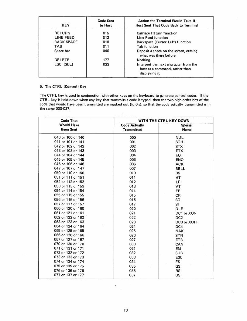
Code Sent Action the Terminal Would Take If KEY to Host Host Sent That Code Back to Terminal
RETURN 015 Carriage Return function LINE FEED 012 Line Feed function BACK SPACE 010 Backspace (Cursor Left) function TAB 011 Tab function Space bar 040 Deposit a space on the screen, erasing
what was there before DELETE 177 Nothing ESC (SEL) 033 Interpret the next character from the
host as a command, rather than displaying it
5. The CTR L (Control) Key
The CTR L key is used in conjunction with other keys on the keyboard to generate control codes. If the CTRL key is held down when any key that transmits a code is typed, then the two high-order bits of the code that would have been transmitted are masked out (to O's), so that the code actually transmitted is in the range 000-037.
Code That WITH THE CTRL KEY DOWN Would Have Code Actually Special Been Sent Transmitted Name
040 or 100 or 140 000 NUL 041 or 101 or 141 001 SOH 042 or 102 or 142 002 STX 043 or 103 or 143 003 ETX 044 or 104 or 144 004 EOT 045 or 105 or 145 005 ENQ 046 or 106 or 146 006 ACK 047 or 107 or 147 007 BELL 050 or 110 or 150 010 BS 051 or 111 or 151 011 HT 052 or 112 or 152 012 LF 053 or 113 or 153 013 VT 054 or 114 or 154 014 FF 055 or 115 or 155 015 CR 056 or 116 or 156 016 SO 057 or 117 or 157 017 SI 060 or 120 or 160 020 DLE 061 or 121 or 161 021 DC1 or XON 062 or 122 or 162 022 DC2 063 or 123 or 163 023 DC3 or XOFF 064 or 124 or 164 024 DC4 065 or 125 or 165 025 NAK 066 or 126 or 166 026 SYN 067 or 127 or 167 027 ETB 070 or 130 or 170 030 CAN 071 or 131 or 171 031 EM 072 or 132 or 172 032 SUB 073 or 133 or 173 033 ESC 074 or 134 or 174 034 FS 075 or 135 or 175 035 GS 076 or 136 or 176 036 RS 077 or 137 or 177 037 US
13

6. SCROll and COPY Keys
The function of the COpy key is explained in the Copier Users' Manual. On terminals which do not feature an integral electrolytic copier, the COpy key does not function.
The SCROll and COpy keys are unique in that they do not transmit codes to the host, but perform their respective functions locally. The SCROll key is used to request more lines when the terminal is in HoldScreen Mode. The operator types SCROll to command the terminal to let another line onto the screen, and SHIFT SCROll to view another screenful. It is described further in the discussion of Hold-Screen Mode in Section 3.
7. The BREAK Key
Typing the BREAK key causes the transmission line to be forced to its zero state for as long as the BREAK key is held down.
The BREAK function is commonly used to forcibly interrupt the flow of data coming to the terminal. It is provided for users with older software written to operate in Half Duplex. In Half Duplex, only one data communication line exists between terminal and host computer. If the host computer has control of this line, BREAK is the only means of forcing an interrupt. However, since the VT50 has both an input and an output line, it is normally unnecessary to use the BREAK key.
8. The Auxiliary Keypad (VT50H and VT52 only)
The auxiliary keypad contains three blank keys which transmit two-character Escape Sequences. The user can define the meanings of each of these three keys to tailor the keypad to his application.
Keypad Key Code(s) Transmitted to Host
left blank key 033 120 (ESC P) center blank key 033 121 (ESC Q) right blank key 033 122 (ESC R)
The keypad also contains four keys which are labeled with arrows in each of the four directions. They also transmit Escape Sequences. If the host echoes these Escape Sequences back to the terminal, the cursor will move one character position up, down, right, or left (depending on the codes). The host may fail to echo these codes and perform a special function instead. In this case, these four keys will also be user-defined.
up-arrow key down-arrow key right-arrow key left-arrow key
033 101 (ESC A) 033 102 (ESC B) 033 103 (ESC C) 033 104 (ESC D)
The remaining keys on the auxiliary keypad transmit the codes for the numerals and decimal point. The host cannot tell if these keys were typed as opposed to the numeral keys and decimal point key on the main keyboard. In addition, the key labeled ENTER transmits the octal code 015, which is the same code the RETURN key on the main keyboard transmits. Therefore, software which requires much numeric data entry need not be rewritten, because the codes the terminal transmits to it will be the same if the operator chooses to use the numeric pad.
However, if software must be able to distinguish between, for instance, the pressing of the 5 key on the auxiliary keypad and the pressing of the 5 key on the main keyboard, the host can give the terminal a command to place it in Alternate-Keypad Mode. In Alternate-Keypad Mode, the functions of the blank keys and the keys labeled with arrows do not change, but the numeral, decimal point, and ENTER keys all transmit unique Escape Sequences. Now all the keys on the auxiliary keypad are user-definable. (AlternateKeypad Mode is found only in the VT52.)
14

CODE(S) TRANSMITTED TO HOST BY VT50H, or VT52 not in VT52 in
KEY Alternate-Keypad Mode Alternate-Keypad Mode
0 060 033 077 160 (ESC? p) 1 061 033 077 161 (ESC? q) 2 062 033 077 162 (ESC? r) 3 063 033 077 163 (ESC? s) 4 064 033 077 164 (ESC? t) 5 065 033 077 165 (ESC ? u) 6 066 033 077 166 (ESC? v) 7 067 033 077 167 (ESC? w) 8 070 033 077 170 (ESC? x) 9 071 033 077 171 (ESC? y)
056 033 077 156 (ESC ? n)
ENTER 015 033 077 115 (ESC ? M)
None of the keys on the auxiliary keypad are affected by depressing the SH I FT, CAPS LOCK, or CTR L keys.
9. The REPEAT Key
The VT50H and VT52 feature a key labeled REPEAT in the lower right corner of the main keyboard. This key does not transmit any codes by itself. It is used in conjunction with other keys. Any key which transmits a code to the host will transmit that code repeatedly if pressed while the REPEAT key is down. The keys on the auxiliary keypad which transmit more than one code apiece will transmit their sequence repeatedly, if pressed with the REPEAT key down. The rate of repetition may attain 30 characters per second, or it may be limited to a slower rate if the Baud rate is not set to accommodate such rapid transmission.
15

SECTION 3
THE COMMANDS
Section 2 described the ways in which the keyboard can be used to transmit codes to the host. This section describes the actions taken by the terminal when it receives various codes from the host.
DISPLAYABLE CHARACTERS
The codes 040 through 176, which are codes for diplayable characters, can be considered as commands -commands to display on the screen the characters they stand for. When the terminal receives one of these codes, it will display the corresponding character on the screen and move the cursor right one column.
If the cursor was in the rightmost column of the line, it does not move but remains under the character that was just entered onto the screen. If the host sends the terminal another code for a displayable character without explicitly moving the cursor using one of the terminal's commands, this new character will replace the old one. Otherwise, the host can send a series of these codes to the terminal, and the terminal will display the corresponding characters on the screen, left to right, in the order it received them.
The VT50 and VT50H cannot display any character in the range 140 - 176. Th is is the lower-case range. If one of these terminals receives a code in this range, it will subtract 040 from that code, convert the result to a character (by the ASCII code), and display that character on the screen. The cursor will move right as usual, unless it was at the end of a line. The subtraction of 040 which takes place on the VT50 and VT50H has the following effects:
a. The lower-case letters have codes 141 - 172. The upper-case letters have codes 101 - 132. If the VT50 or VT50H receives a code for a lower-case letter, it will convert the code to an upper-case code, and display the upper-case form of the character.
b. If the VT50 or VT50H receives 140 ( , ), it will display @ (100).
c. If the VT50 or VT50H receives 173 ({ ), it will display [ (133).
d. If the VT50 or VT50H receives 174 ( : ), it will display \ (134).
e. If the VT50 or VT50H receives 175 ( ~), it will display] (135).
f. If the VT50 or VT50H receives 176 ("-'), it will display 1\ (136).
Appendix 8 summarizes this conversion.
CONTROL CODES
Some codes or sequences of codes are interpreted by the terminal as commands rather than displayed as characters on the screen.
Of the 128 codes in the ASCII set, 33 are considered to be control codes. Th is means that they do not represent characters that can be displayed on the screen. Some are meant to be interpreted as commands. Eventually, however, with only 33 control codes, terminals are going to run out of codes to stand for all their various functions. Therefore, one of the control codes, called ESC (Escape), has been reserved for use to declare that the code that follows it, though it represents a character that could be displayed on the screen, must instead be interpreted as a command. For example, if the terminal receives the code 102 , it will display a "8" on the screen. But if it receives 033, the code for ESC, and then the 102, it will not display a "8" but instead will perform a special command.
Commands exist to position the cursor, erase part or all of the information on the screen, place the terminal in special modes in which it behaves differently, and force the terminal to identify itself to the host.
When a VT50 series terminal receives ESC, it will interpret rather than display the next displayable character. This displayable character should directly follow ESC. It is known as the final character of the Escape Sequence. If a control code is sent to the terminal between the ESC and the final character, the function specified by the control code is performed when the control code is received, and the function specified by the Escape Sequence is performed when the final character is received.
16

If the VT50 or VT50H receives ESC ESC from the host, the second ESC will cancel the Escape Sequence, so that the next displayable character the terminal receives will be displayed as usual. If the VT52 receives ESC ESC, it wit.1 stilt be prepared to interpret rather than display the next displayable character.
FILLER CHARACTERS
Some terminals cannot process characters and commands as fast as the codes come in from the host. These terminals require the host to send several meaningless characters, called "fillers", to the terminal in order to "pass the time" until the terminal is ready to process more data. The control codes 000 (NU L) and 177 (DEL) are most often used as fillers. Although no DECscope requires the host to send fillers at any time, the DECscope will ignore 000 and 177 when it receives them, so that software which uses these characters as fillers will not have to be rewritten to eliminate them.
SYNCHRONIZATION
The only time the terminal fails to keep up with the data coming in from the host is when it is passing data to the electrolytic copier. In this case, rather than require the host to compute a complicated formula for how many fillers to send out and when, the terminal calculates on its own when it is getting behind, and sends a signal to the host to request it to stop transmitting. This signal is the control code XOFF (023). When the terminal has reduced its backlog, it sends another signal.to the host to tell it to resume. This signal is XON (021). The terminal depends on the host to suspend its transmission when the host receives XOFF, and to resume the transmission from the point at which it left off when it receives XON.
But the host's response to XOFF will not be immediate, if simply because it will take a finite amount of time for the XOFF code to travel down the wire to the host. After the terminal transmits XOFF to signify that it cannot process more data, it may receive several more codes before the host actually stops transmitting.
Therefore, the terminal places these codes in an internal buffer called the Silo, to be processed at a later time. When the terminal is ready to process more codes, it will take the codes out of the Silo in the order they were received in, and process them before it sends XON to the host to request more data.
Effectively, there is room for 13 codes in the Silo. For most applications, this is sufficient to allow for transmission delays. It is not meant to be sufficient to let the host ignore XOFF. If the Silo fills up and the host keeps sending, the Silo is said to "overflow". The codes in the Silo are removed and processed by the terminal in the order in which they were received, regardless of the situation at the terminal which had caused the delay.
One cause of the Silo overflowing is excessive processing time and transmission-line delay. To illustrate, if the DECscope were connected to the host such that messages from the terminal reached the host ten seconds after leaving the terminal, you can see how an XOFF sent by the terminal might not reach the host in time to halt the host's transmission.
Another cause for Silo overflow is the use of a receiving speed which is much more rapid than the transmitting speed. If the DECscope were set to receive at 9600 Baud while transmitting at 300 Baud, 9600/300 = 32 characters which could be received in the time it took the terminal to send XOFF. This problem would not exist if the transmission speed were also 9600 Baud. Thus, the use of high Baud rates is not by itself a cause of synchronization failure - although it does magnify the effect of long delay times.
The sufficiency of the DECscope's Silo can be calculated using the formula
(D + d + P) y + 2: + 2
to yield the number of characters that the VT50 would have to buffer at worst. If this equation produces a number 13 or less, the DECscope will fit the application since the effective length of the Silo is 13 characters. I n the equation above,
17

D is the transm ission delay from term ina I to host. d is the transmission delay from host to terminal. P is the processing delay.
(P is the interval from the time the host physically receives XOFF and the time software transmits its last character before stopping in response to the XOFF.) All three of these times are in seconds in the above equation.
Y is the receiving speed of the terminal. X is the speed at which the terminal transmits.
Both of these times are expressed in characters per second (char/sec). 9600 Baud = 960 char/sec; 1200 Baud = 120 char/sec, etc.; but 110 Baud = 10 char/sec. The 2's in the formula reflect the fact that the host's interface hardware and that of the DECscope - that is, the UAR/Ts - will buffer two characters in each direction.
As an example, consider a VT50 communicating to a host at 300 Baud (transmitting and receiving) over a telephone line. The telephone company specifies that the worst-case transmission delay is not greater than 50 msec. In this example, the processing delay was zero since, when the host received XOFF, it trapped to a routine which disabled output. So the last character the host transmitted to the terminal would occur before receiving XOFF. Since transmitting and receiving speeds are both 30 char/sec, the equation is:
(.050 + .050 + 0) 30 + 2 (30) + 2 7 (30)
A terminal with a 7-character input buffer is required. The DECscope, with 13-character Silo, is adequate for the application.
When the DECscope is set for Local Copy, the effective length of the Silo is reduced to 12 characters, since the XOFF transmitted by the terminal goes into its own Silo. Note that in this situation the operator could cause the Silo to overflow by continuing to type, since the characters typed will likewise go into the Silo.
Appendix A contains a table which lists, for each combination of receiving and transmitting Baud rates, the time (D + d + P) by which the host must be able to respond to XOFF in order to prevent Silo overflow.
SOFTWARE MUST RESPOND TO XON/XOFF if the electrolytic copier is being used and there is a possibility that the host will be sending data to the terminal while the copier is running.
In Hold-Screen Mode, the terminal uses these same XOFF and XON signals again, not because the terminal cannot keep up with the data from the host, but simply to hold the present data on the screen until the operator gives the terminal a request for new data. SOFTWARE MUST RESPOND TO XON/XOFF if Hold-Screen Mode is being used.
18

BASIC CURSOR MOVEMENT COMMANDS
1. LINE FEED (VT50, VT50H, VT52)
invoked by LF (012)
The cursor is moved down one character position to the same column of the line below where it was.
If the cursor was on the bottom line of the screen to begin with, it stays where it was, but all the information on the screen moves up one line. The information that was on the top line is lost from the screen; a new bottom line appears. This process is called an upward scroll.
2. CURSOR DOWN (VT50H and VT52 only)
invoked by ESC B (033 102)
The cursor is moved down one character position to the same column of the line below where it was.
If the cursor was on the bottom line of the screen to begin with, it stays where it was, and no scroll occurs.
3. REVERSE LINE FEED (VT52 only)
invoked by ESC I (033 111)
The cursor is moved up one character position to the same column of the line above the one it was on.
If the cursor was on the top line to begin with, it stays where it was, but all the information on the screen appears to move down one line. The information that was on the bottom line of the screen is lost; a new blank line appears at the top line. This process is called a downward scroll.
4. CURSOR UP (VT50, VT50H, VT52)
invoked by ESC A (033 101)
The cursor is moved up one character position to the same column of the line above the one it was on.
If the cursor was on the top line to begin with, it stays where it was, and no scroll occurs.
5. SPACE (VT50, VT50H, VT52)
invoked by 040
The character at the cursor position is erased, and the cursor moves one column to the right. (If the cursor was at the end of the line to begin with, it does not move.)
You can view Space as a command to erase one character, or you can view it as simply a displayable character which is blank and erased the original character by replacing it on the screen.
Programs written for teleprinters which position the carriage (or cursor) by returning it to the left of the line and Spacing it over to the desired column may have to be rewritten, in view of the fact that the DECscope's Space command erases data. The following command should be used instead of Space in order to move the cursor to a certain column, over data that has already been written on the screen.
19

6. CURSOR RIGHT (VT50, VT50H, VT52)
invoked by ESC C (033 103)
The cursor is moved one column to the right. (If the cursor was at the end of the line to begin with, it does not move.) No character on the screen is erased.
7. BACKSPACE, OR CURSOR LEFT (VT50, VT50H, VT52)
invoked by BS (010) (In the VT50H and VT52, an Escape Sequence - ESC D (033 104) - is provided to invoke this same function for symmetry.)
The cursor is moved one column to the left. (If the cursor was at the start of the line to begin with, it does not move.) No character on the screen is erased.
Even though the DECscope responds to the Backspace code, programmers are reminded that it is impossible to produce a composite character on the screen by backspacing and "overprinting" one character with another. On the DECscope, as on most video terminals, the character which was overprinted will vanish from the screen since only one character can occupy a character position at any time.
THE ADVANCED CURSOR MOVEMENT COMMANDS
8. CARRIAGE RETURN (VT50, VT50tj, VT52)
invoked by CR (015)
The cursor is moved to the start (leftmost column) of the line it was in. If it was there to begin with, it stays there.
9. CURSOR HOME (VT50, VT50H, VT52)
invoked by ESC H (033 110)
The cursor is moved to the HOME position - the character position at the upper left corner of the screen. If it was there to begin with, it stays there.
10. TAB (VT50, VT50H, VT52)
invoked by TAB (011)
The cursor moves to the right at least one column, and continues moving right until it reaches a horizontal TAB stop. It stays in the same line it was in. If we number the columns from 1 (leftmost column) to 80 (rightmost column), the TAB stops are fixed in columns 9, 17, 25,33,41,49, 57, 65 and 73. If the cursor was at a TAB stop to begin with, it moves rightward to the next TAB stop. If the cursor was in columns 73 - 79, it simply moves rightward one column. If the cursor was in column 80, it does not move.
11. DIRECT CURSOR ADDRESSING (VT50H and VT52 only)
invoked by ESC Y (033 131)
The next code after ESC Y that the host sends to the terminal will not be displayed but will be interpreted as specifying one of the lines on the screen. The character the terminal receives after that will not be displayed but will be interpreted as specifying one of the columns on the screen. The cursor will be moved to the character position at the specified line and column. The complete Direct Cursor Addressing command has this form:
ESC Y line# column#
20

and consists of four characters from the host. Control codes or other Escape Sequences should not be embedded in this string of four characters. (Doing so will produce unspecified results.)
For "line#", the host sends the octal code 040 to specify the top line of the screen, 041 to specify the line below the top line, and so forth. On the VT50H, 053 specifies the bottom line. On the 24-line VT52, 067 specifies the bottom line. If line# does not specify a line that exists on the screen, the VT50H will move the cursor to the bottom line of the screen. However, the VT52 will not move the cursor vertically if the vertical parameter is out of bounds. A Direct Cursor Addressing command with the first parameter greater than 067 can be issued to the VT52 to move the cursor arbitrarily in the horizontal direction without the flickering of the video that the full Direct Cursor Addressing command can cause.
For "column#,', the host sends the octal code 040 to specify the leftmost column in a line, and 157 to specify the rightmost column. If column# is greater than 157 and, therefore, does not specify a column that exists on the screen, the cursor is moved to the rightmost column on a line on all models.
The VT50H provides an alternate form for this command which uses a single control code, SO (016), instead of the Escape Sequence.
SO line# column#
This form is provided for compatibility with the VT05 video terminal. The VT52 and future terminals will not accept this form of the Direct Cursor Addressing command.
SCREEN ERASURE COMMANDS
In addition to the screen erasure commands listed here, remember that Space can be thought of as a screen erasure command.
12. ERASE TO END-Of-LINE (VT50, VT50H, VT52)
invoked by ESC K (033 113)
All the information at the cursor position and rightward to the end of the line is erased (spaces are deposited at those character positions).
If the cursor is at the rightmost column on a line, the character at the cursor position will be the only character to be erased. If the cursor is at the leftmost column on a line, the entire line will be erased.
13. ERASE TO END-Of-SCREEN (VT50, VT50H, VT52)
invoked by ESC J (033 112)
All the information from the cursor position to the end of the screen is erased. This function does what Erase to End-of-Line do~s and, in addition, erases the information in every line below the line the cursor is on.
If the cursor is at the lower right corner of the screen, one character will be erased. If the cursor is at the HOME position of the screen, all the information on the screen will be erased.
21
AUDIBLE SIGNALS
The DECscope has two audible signals. The terminal makes a clicking sound every time a key is typed to let the operator know that the keystroke registered with the terminal. (Keys which simply modify the function of other keys - the CTRL, REPEAT and two SHIFT keys - do not make the terminal click. Nor does the BREAK !<ey. The VT52's CAPS LOCK key does not make the terminal click, but the key itself clicks as it locks or unlocks.)
On the VT50 and VT50H, the key-click sound can be switched off using a switch on the underside of the unit (behind the metal screen) if absolute quiet is required.
The terminal also has a buzzer or "bell". The host can command the terminal to make this sound.
14. RING THE BELL (VT50, VT50H, VT52)
invoked by BEL (007)
On the VT50 and VT50H, the bell also rings when a key is typed with the cursor in column 72, to warn the operator that the cursor is approaching the right margin. Output from the host which approaches the right margin does not cause the bell to ring.
DISTINGUISHING DIFFERENT MODELS
Software can determine what features are available on the terminal with which it is in contact. Applications which require lower-case display, or which have data to be output to a copier, can determine whether to proceed or, for instance, warn the operator to use a properly equipped terminal. The configuration of DECscopes around a computer system can be changed without having to adjust the software.
15. IDENTIFY TERMINAL TYPE (VT50, VT50H, VT52)
invoked by ESC Z (033 132)
When the terminal received ESC Z, it transmits a three-character Escape Sequence to the host. This Escape Sequence tells the host two things:
a. That the terminal is switched on, connected to the host, and responding to commands.
b. Whether the terminal is a VT50, VT50H or VT52, and whether an integral electrolytic copier is present.
During the time it is transmitting the three-character Escape Sequence, the terminal will disable the keyboard so that characters typed will not be embedded in the Escape Sequence. Under no circumstances will the keyboard be locked for more than half a second. As the transmitting Baud rate is set higher so that it takes less time to transmit the three characters, the time for this command will drop to under 1/15 second.
Here are the Escape Sequences that various models will transmit when they receive this command:
Without Copier With Copier
VT50 ESC/ A not offered VT50H ESC/ H ESC / J VT52 ESC/ K ESC / L VT55 ESC /C ESC/C
The host should not interpret the reception of one of the Escape Sequences from the "With Copier" column as meaning that the copier has paper in it and is ready to print. Each terminal will send one Escape Sequence in response to this command at all times, regardless of the state of the copier.
22

HOLD-SCREEN MODE
Hold-Screen Mode allows the operator to control the rate at which data enters and leaves the screen. Th is is important because the DECscope can operate at such fast speeds that data from the host might remain on the screen for only a few seconds before it scrolls up and off the top of the screen to make way for new data. Other terminals simply allow the data to leave the screen and be lost, regardless of whether the operator has had time to read it. The DECscope does this, too, when it is not placed in Hold-Screen Mode.
The DECscope has a synchronization scheme with the host, which was described at the start of this section. Whenever, for any reason, it cannot process data from the host, it automatically transmits the control code XOFF (023). When it is ready again, it transmits XON (021). The terminal depends on the host to suspend its transmission promptly when the host receives XOFF from the terminal, and resume the transmission where it left off upon receiving the XON., When software places the terminal in Hold-Screen Mode, the terminal simply refuses to perform scrolls. If the host commands it to scroll by sending the terminal a LF (012) when the cursor is on the bottom line, the terminal will place the LF in the Silo to be executed later, and send XOFF to the host. The XOFF means that the terminal is not ready for more data from the host, because the terminal assumes that the operator is not ready for more.
The operator tells the terminal that he is ready to see more data - specifically, one more line of data - by pressing the SCROLL key. When he does so, the terminal processes the LF character out of the Silo. When it does this, a scroll occurs. Then the terminal takes from the Silo any other characters that may have arrived from the host before the host responded to the XOFF and suspended its output. Each character in the Silo is displayed on the screen or, in the case of commands, executed exactly as if it had just been received - unless it is another LF causing another scroll. If the terminal encounters a LF in the Silo, it stops processing characters out of the Silo until the operator types the SCROLL key again.
If the terminal processes all the characters in the Silo without finding a LF, it transmits XON to the hostto notify it that the terminal is again ready to receive characters. It will display all the characters and execute all the commands until it again is ordered to perform a scroll. Then it will again send XOFF, store the LF in the Silo, and wait for the operator to press the SCROLL key again.
If, after the terminal transmits XOFF, the host keeps transmitting to such an extent that the Silo fills up completely, then, rather than allow data to be lost, the terminal will perform the scroll it was commanded to perform despite Hold-Screen Mode and remove the characters from the Silo and interpret them, reducing the backlog. However, the terminal does not exit Hold-Screen Mode; if it encounters another command to scroll the display, either within the Silo or directly from the host, it will not scroll, and it will begin to buffer incoming characters once again.
The operator types the SCROLL key to request that another line be admitted to the screen. The terminal translates this request into "start" and "stop" commands - XON and XOFF - and sends them to the host in such a way that just enough data comes to the terminal to satisfy the operator's request for one more line.
The operator can type the SCROLL key with the SH I FT key down to make a request for a new screenful of data. As with the unshifted SCROLL request, the terminal begins to process characters again and sends XON to the host when the characters that accumulated in the Silo have all been processed. But the shifted SCROLL request tells the terminal to allow an entire screenful of new data to enter the screen before shutting off the transmission from the host. A 12-line DECscope will perform 12 scrolls before sending XOFF; a 24-line DECscope will perform 24 scrolls.
Using Hold-Screen Mode, therefore, software can output controlled, page-by-page output to the terminal. The software need not maintain counters of how many lines have been output to the terminal since the last request. Since the terminal calculates when its own screen has been filled with new data and takes the initiative to notify the host, the software does not need to know the capacity of lines of the terminal it is outputting to. The same software will produce page-by-page output to 12-line DECscopes and 24-line DECscopes.
23

16. ENTER HOLD-SCREEN MODE (VT50, VT50H, VT52)
invoked by ESC [ (033 133)
The terminal enters Hold-Screen Mode. Data will not be allowed to scroll off the screen without permission from the operator by use of the SCROLL key. After entering Hold-Screen Mode, the first command which would cause a scroll to occur will not be immediately processed, and the terminal will send XOFF to the host.
Hold-Screen Mode remains in effect until the following command disables that feature.
17. EXIT HOLD-SCREEN MODE (VT50, VT50H, VT52)
invoked by ESC \ (033 134)
The terminal exits Hold-Screen Mode. Data will be allowed to scroll off the screen if it has to in order to make room for new data coming from the host.
ALTERNATE-KEYPAD MODE
The codes that the Auxiliary Keypad is capable of transmitting are listed in Section 2, but in the VT52 there are two sets of codes that software can select between by issuing these commands.
18. ENTER ALTERNATE-KEYPAD MODE (VT52 only)
invoked by ESC = (033075)
The terminal enters Alternate-Keypad Mode, in which the numeral keys, decimal point key, and ENTER key transmit unique Escape Sequences, allowing software to distinguish between them and keys on the main keyboard, and to assign its own meaning to each key.
Alternate-Keypad Mode will not be in effect until the host issues this command and, once enabled, will remain in effect until the host uses the following command to disable that feature.
19. EXIT ALTERNATE-KEYPAD MODE (VT52 only)
invoked by ESC ) (033076)
The terminal exits Alternate-Keypad Mode. Now the numeral, decimal point, and ENTER keys transmit codes that are indistinguishable from the codes transmitted by the numeral, decimal point, and RETURN keys on the main keyboard. Applications which do not need to redefine the meanings of these twelve keys will work correctly with the operator using the keypad for entry of numeric data.
GRAPHICS MODE
There are 33 special symbols which can be displayed on the screen of the VT52. These special symbols can be entered in the screen only by placing the terminal in Graphics Mode. Normally, the codes 136-176 stand for the lower-case letters and some symbols. In Graphics Mode, each code in this range will callout one of the special symbols to be placed on the screen.
Codes 040 - 135 are unaffected. The symbols they stand for can be placed on the screen whether or not the terminal is in Graphics Mode.
The VT52 uses the control codes to mark the position of the special symbols in its internal memory. Therefore, the special symbols and the lower-case letters can coexist on the screen. The special symbols will remain on the screen where they were entered even if the terminal is subsequently taken out of Graphics Mode.
24

20. ENTER GRAPHICS MODE (VT52 only)
invoked by ESC F (033 106)
When codes in the range 136 - 176 are received, they will be converted to the special symbols before being placed on the screen. This remains true until the terminal receives the following command.
21. EXIT GRAPHICS MODE (VT52 only)
invoked by ESC G (033 107)
The codes 136 - 176 resume their standard (ASCII) meanings.
Appendix B describes the appearance of the special symbols. They are determined by the VT52's internal character-generator card. Custom-programmed cards can be plugged in for special applications. On VT52s with serial numbers under 3000, the character-generator is non-standard; the appearance of the special symbols on these terminals is unspecified.
25

ENVIRONMENT
OFF-LINE
FULL DUPLEX WITH LOCAL COpy
FULL DUPLEX
DESIRED BAUD RATE
APPENDIX A
THE BAUD-RATE SWITCHES and Silo Sufficiency Chart
S1-S2 SWITCH POSITIONS
Trans. Receiv. VT52 VT50(H)
9600 9600 l-G l-G 4800 4800 n.a. l-F 2400 2400 l-F l-E 1200 1200 l-E 1-0 600 600 1-0 l-C 110 110 1-8 1-8
9600 9600 2-G 2-G 4800 4800 7-A 2-F 2400 2400 2-F 2-E 1200 1200 2-E 2-D 600 600 2-D 2-C 300 300 4-A n.a. 150 150 5-A n.a. 110 110 (2S8) 2-8 2-8
9600 9600 3-G 3-G 4800 4800 7-C 3-F 2400 2400 3-F 3-E 1200 1200 3-E 3-D 600 600 3-D 3-C 300 300 4-C 4-A 150 150 5-C 5-A 110 110 (2S8) 3-8 3-8 75 75 6-C 6-A
4800 9600 7-G n.a. 4800 2400 7-F n.a. 4800 1200 7-E n.a. 4800 600 7-0 n.a. 4800 110 (2S8) 7-8 n.a.
300 9600 4-G 4-G 300 4800 n.a. 4-F 300 2400 4-F 4-E 300 1200 4-E 4-0 300 600 4-0 4-C 300 110 (2S8) 4-8 n.a.
150 9600 5-G 5-G 150 4800 n.a. 5-F 150 2400 5-F 5-E 150 1200 5-E 5-0 150 600 5-0 5-C 150 110 (2S8) 5-8 n.a.
26
MAXIMUM DELAY TIME*
These first five settings are functionally equivalent. (Since no inter-device com-· munication occurs, the 8aud rate is irrelevant.) If the terminal is set for OFF-LINE use at 110 8aud, the rate of repetition achieved with the REPEAT key will be noticeably slower.
8.3 msec 16.7 msec 33.3 msec 67 msec
133 msec 267 msec 533 msec 800 msec
9.4 msec 18.8 msec 37.5 msec 75 msec
150 msec 300 msec 600 msec 900 msec
1200 msec
7.3 msec 41.7 msec 88 msec
179 msec 1100 msec
(negative) (negative) (negative)
25 msec 117 msec
1033 msec
(negative) (negative) (negative) (negative)
50 msec 967 msec

DESIRED S1-S2 BAUD RATE SWITCH POSITIONS MAXIMUM
ENVIRONMENT Trans. Receiv. VT52 VT50(H) DELAY TIME*
FULL DUPLEX 75 9600 6-G 6-G (negative) (Cont.) 75 4800 n.a. 6-F (negative)
75 2400 6-F 6-E (negative) 75 1200 6-E 6-D (negative) 75 600 6-D 6-C (negative) 75 110 (2SB) 6-B n.a. 833 msec
n.a. This combination of transmitting and receiving Baud rates is not available on this terminal.
(2SB) - At these settings, the terminal will supply an extra stop bit on each character it transmits, and wait for one on each character it receives. A total of 11 bits per character, rather than 10, will be used at these settings. See the warning under "Serial Encoding" near the beginning of the "FOR PROGRAMMERS" portion of this manual.
The host must receive and respond to an XOFF signal from the terminal within this interval from the time the VT50 transmitted it, to ensure that the Silo does not overflow. The indicated times include processing time as well as transmission delays both ways. "(negative)" indicates that Silo overflow may occur regardless of delay and processing time. See "SYNCHRONIZATION" in Section 3 of the Programmers' portion of this manual for a complete description of the XOFF signal.
THE POSITIONS OF SWITCH S1
Switch 1 generally dictates transmitting speed. In the "match" positions, indicated with an asterisk, the transmitting speed will be the same as the receiving speed, which must be indicated by the setting of switch S2. Position 1 is the most counterclockwise position.
1 - Off-Line * 2 - Full Duplex with Local Copy * 3 - Full Duplex * 4 - 300 Baud 5 - 150 Baud 6 - 75 Baud 7 - 4800 Baud (VT52 only)
THE POSITIONS OF SWITCH S2
Switch S2 generally dictates receiving speed. In the "match" positions, indicated with an asterisk, the receiving speed will be the same as the transmitting speed, which must be indicated by the setting of Switch Sl. Position A is the most counterclockwise position.
VT52 VT50(H)
A - Match (Bell 103) - Local Copy * A - Match (Bell 103) * B - 110 Baud B - 110 Baud C - Match (Bell 103) * C - 600.Baud D - 600 Baud D - 1200 Baud E - 1200 Baud E - 2400 Baud F - 2400 Baud F - 4800 Baud G - 9600 Baud G - 9600 Baud
If both switches are in a "match" position, the terminal will not function - the key-click will cease, and characters will cease to be transmitted and received. The following switch positions are illegal on the VT52:
1-A 1-C 2-A 2-C 3-A 3-C
The following switch positions will cause the VT50 and VT50H to fail:
1-A 2-A 3-A 7-A 7-B 7-C 7-D 7-E 7-F 7-G
Transmission and reception will resume if the switches are reset to a valid position.
27

APPENDIX B \
DISPLAY OF THE CODES 136-176
This appendix describes the appearance of the VT52's special symbols, which are entered into the screen using the codes 136-176 and with the terminal in Graphics Mode. It also specifies the lower-case-to-uppercase conversion which occurs on the upper-case-only VT50 and VT50H.
When the ... a VT52 will display this . .. but the VT50(H) terminal symbol on the screen ... will display this receives In Graphics Not In symbol on the this code ... Mode Graphics Mode screen ...
136 blank A A
137 blank - -140 reserved
, @
141 solid rectangle a A 142 11 b B 143 31 c c 144 51 d D 145 71 e E 146 degrees f F 147 plus or minus g G 150 right arrow h H 151 ellipsis i I 152 divide by j J 153 down arrow k K 154 bar at scan 0 I L 155 bar at scan 1 m M 156 bar at scan 2 n N 157 bar at scan 3 0 0 160 bar at scan 4 p P 161 bar at scan 5 q Q
162 bar at scan 6 r R 163 bar at scan 7 s S 164 subscript 0 t T 165 subscript 1 u U 166 subscript 2 v V 167 subscript 3 w W 170 subscript 4 x X 171 subscript 5 y Y 172 subscript 6 z Z 173 subscript 7 { [ 174 subscript 8 I \ 175 subscript 9 } ] 176 paragraph '" A
USES OF THE SPECIAL SYMBOLS
A. The codes 154-163 cause eight horizontal lines at various scans within the character position to be displayed. These bars can be used to paint a bar-graph on the screen with more accuracy than would be possible using only minus signs and underlines, for instance.
B. The codes 142-145 ("1/","3/","5/", and 117/") are used preceding the subscripts to form fractions. In
particular, the fractions l/S, 1/4 , 3/s , 112, 5/S, 3/4 , and 7/8 can be formed using these four symbols and the subscripts.
28
c. The ellipsis (151) appears as three dots in the character position (. .. ). The spacing of these three dots· is such that several of these symbols placed adjacent to one another in the screen will produce a smooth I ine of dots.
D. The symbols produced by the codes 136-140 are reserved for possible future use.
29

Dimensions
Weight
Operating Environment
Line Voltage
Line Frequency
Power Consumption
Power Line Hash Filter
Overload Protection
Case Material
Screen Phosphor
SUMMARY OF SPECIFICATIONS
The DECscope Video Terminals
Height: 360 mm (14.1 in.)
Width: 530 mm (20.9 in.)
Depth: 690 mm (27.2 in.)
Minimum Table Depth: 450 mm (17.7 in.)
20 kg (44 Ibs)
DEC STD 102 - Class B environment 10 deg C to 40 deg C (50 deg F to 104 deg F) Relative humidity 20% to 80%, no condensation Maximum wet bulb 25 deg C (77 deg F) Minimum dew point 2 deg C (36 deg F)
(US model) 100-126V
(European model) 191-238V or 209-260V
(US model) 60 Hz, accurate to 1 Hz
(European model) 60 Hz or 50Hz, accurate to 1 Hz
110 Watts
Low leakage Balun type
Circuit Breaker
Injection-Molded Noryl
P4
30

NOTES

NOTES