dectro catalog qülpmen $r - american radio history ... · -sorin continental ... capability in rf...
TRANSCRIPT

M
Continental Dectro
Ra dig $r °adc
qülpmen Catalog
1.981 119$$ : , ,
www.americanradiohistory.com

Continental's Customer Service Is The Industry's Best!
Call Anytime, Day Or Night.
Main Offices: (214) 381 -7161
Parts: (214) 327 -4532
Engineering Service: (214) 327 -4533
Telex: 73398
Cable: CONTRONICS
Continental Electronics, a Division of Varian Associates, Inc. 4212 South Buckner Blvd., PO Box 270879 Dallas, Texas 75227 Ph: (214) 381 -7161
www.americanradiohistory.com

All Continental Electronics AM transmitters listed herein are complete with ooerating tubes, crystals, instruction manuals, Automatic Peak Controller and are factory tuned and tested on frequency and output impedance specified by the customer. Fac- tory test data is recorded and furnished with the equipment.
TYPE 317C -2 50 kW AM BROADCAST TRANSMITTER With automatic emergency power reduction 18.20 kW $166,000.00 Power reduction to 10 kW or 25 kW 4,200.00 4CX35000C Spare PA Tube 7,020.00 3CX3000A1 Spare Mod Tube 629.00 4-400C Spare AF or RF Driver Tube 159.00
TYPE 316F 10 kW AM BROADCAST TRANSMITTER $ 49,360.00 Power reduction to 5 kW, 2.5 kW, 1 kW, .5 kW 1,120.00 Remote Control Interface Panel 1,150.00 4CX15000A Spare Tube 1,720.00
TYPE 315R -1 5 kW AM BROADCAST TRANSMITTER $ 39,000.00 Power reduction for 2nd power level N/C Power reduction for 3rd power level 590.00 Remote Control Interface Panel 435.00 Filament Voltage Regulator 540.00 3CX3000F7 Spare Tube 740.00
TYPE 314R -1 1 kW AM BROADCAST TRANSMITTER S 16,000.00 Power reduction to 2nd power level N/C Power reduction for 3rd power level 590.00 Filament Voltage Regulator 270.00 3 -500Z Spare Tube 155.00
TYPE 517C -1 50 kW AIR COOLED DUMMY LOAD S 10,950.00
TYPE 516F 10 kW /5 kW AIR COOLED DUMMY LOAD S 1,600.00 Add for Delta Meter 450.00 Add for EIA Flange Connector 230.00
116937.1 MAGNIPHASE LINE PROTECTION SYSTEM FOR
5/10 kW 850.00 116937 -2 MAGNIPHASE LINE
PROTECTION SYSTEM FOR 50 kW 1 050.00
TYPE 212R1 AUDIO ROCK 10,
Base Price 10,700.00
TYPE 212P -2 MARK 8,
Base Price 6,350.00
All Continental Electronics FM transmitters listed
herein are comnl "te with exciter, operating tubes,
crystals, instruction manuals and built -in harmonic filter. Price includes factory tuning and testing on
customer's frequency. Test data is recorded and
furnished with each transmitter.
TYPE 817R -4 55 kW FM
BROADCAST TRANSMITTER $126,175.00 TYPE 817R -1 50 kW FM
BROADCAST TRANSMITTER 121,160.00 Add for second exciter with manual switching 7,179.00 Add for second exciter with automatic switching 9,750.00
Add for combiner with automatic switching 31,250.00 4CX250B Spare Tube 86.00 4CX15000A Spare Tube 1,720.00
TYPE 817R -2 40 kW FM
BROADCAST TRANSMITTER 116,950.00 Add for second exciter with manual switching 7,179.00 Add tor second exciter with automatic switching 9,750.00 Add for combiner with automatic switching 21,110.00 4CX250B Spare Tube 86.00 4CX15000A Spare Tube 1,720.00
TYPE 816R -4 27.5 kW FM -;2,9
TRANSMITTER 54,750.00 TYPE 816R -3 25 kW FM ¿ gC
TRANSMITTER 52,500.00 TYPE 816R -2 20 kW FM
TRANSMITTER 47,750.00 Remote Control Interface 371.00
4CX250B Spare Tube 86.00
4CX15000A Spare Tube 1,720.00
TYPE 816R -1A 10 kW FM t -) C TRANSMITTER S 38,950.00 Remote Control Interface 371.00 4CX250B Spare Tube 86.00 4CX10000D Spare Tube 1,420.00
5°) 'Sa
TYPE 814R -1 2.5 kW FM
TRANSMITTER S 24,000.00 Remote Control Interface 371.00 5CX1500A Spare Tube 743.00
TYPE 510R -1 20 WATT FM
EXCITER (MONO) S 5,625.00 786V -1 Plug -in Stereo Generator 1,853.00
786W -2 Plug -in SCA Generator 1,024.00
785E -1 Plug -in STL/Baseband Interface 328.00
S
PRINTED IN U.S.A. 51-35(2)
www.americanradiohistory.com

Continental Also Designs And Manufactures:
Antenna Matching Networks Directional Antenna Phasing
and Matching Systems Transmitter Combining
Equipment Multi- transmitter Diplexing/
Multiplexing Systems
This equipment is custom built to exacting customer requirement and prices will be quoted on receipt of engineering data or specifications.
All prices are quoted FOB Dallas, Texas and do not include any duty, Federal, State, Sales or Use taxes, and are subject to change without notice. Continental Electronics will submit in writing a firm, fixed price proposal for the desired equipment, on request.
Please contact the Broadcast Sales Department for additional information about Continental equipment.
Northeast Northwest
Keith Leach P. 0 Box 16
Newton. NJ 07880 (201) 383.8797
Southeast
John Hutson 805 Skyland Heights Apts. Asheville, NC 28803 1704) 687 1016
Dave Hultsman 2280 Rockcreek Trail Birmingham, AL 35226 1205) 822 1078
John Abdnour P. 0. Box 575
Streator, IL 61364 1815) 672 -8585
Torn Cauthers 1215 SE 73rd Ave. Portland, OR 97215 1503) 254 -2818
Southwest
Steve Schott P. O. Box 2008 Plano, TX 75074 1214) 423-3644
Midwest
Jim Littlejohn 670 North Branch Rd.
Maple Plain, MN 55359
(612) 479.2633
West
Barry Ariaz 106 Louann Ln Hendersonville, TN 37075 1615) 822.0258
Steve Keating 7225 Hollywood Blvd. Suits 105 Hollywood, CA 90046 1213) 851 -6380
GALL AS 're XAO S1-35(1)
31,)eKvr t,1 4 A5.
L-11-t
- 6v-- ao7 ,
TRANSMITTER DOMESTIC PRICE LIST
DECEMBER 1, 1982
3aD CRAIG Ntiklrr',1\ \
-Sorin Continental Electronics Mfg. Co. 4212 South Buckner Boulevard Mad.Box 270879 Dallas. Texas 75227 Phone. 381-7161 TELEX: 73398 Cable CONTRONICS
www.americanradiohistory.com
Introduction
1986 , 4 O years 1946
of excellence in
INTRODUCTION Continental Electronics, a Division of Varian
Associates, Inc., is an engineering- oriented company that specializes in the design, development and production of low, medium and high power radio frequency transmitters for radio broadcast, communications, radar and scientific research applications.
The company was founded in 1946 with the express purpose of creating an extensive capability in RF product design.
Since its founding, Continental has estab- lished an unmatched record of achievement in the area of high power RF transmitters and amplifiers. Many of the company's innovations have advanced the state -of -the -art; most of its work has been of a pioneering type and the kind of work normally associated with the leading edge of technology.
Continental's commitment to excellence is reflected in the workmanship and operational performance of numerous radio /electronic products which bridge the spectrum from ELF to UHF, S -band and beyond, ranging in power from kilowatts to megawatts.
Continental broadcast transmitters are used throughout the world by commercial and government radio stations for local, regional and international broadcasting.
In addition to high power medium and shortwave broadcast transmitters, Continental offers broadcasters a complete line of AM mediumwave transmitters from 1,000 to 50,000 watts, and FM transmitters from 50 watts to 70,000 watts; transmitter combiners and diplexers, phasing and coupling systems, FM antennas, miscellaneous RF and studio equipment.
This catalog gives a brief product overview of the radio broadcast equipment available from Continental.
For performance data, specifications, pricing and delivery information, contact your local Continental sales representative (see pages 108 - 111).
PRODUCT WARRANTY All products, specifications and prices in this
catalog are subject to change without notice; all products are subject to prior sale; no warranty or guarantee as to product availability or performance is given or implied. Some products shown in this catalog are not manufactured by Continental; they are listed for the convenience of Continental's customers to show typical examples of RF- related equipment available in the marketplace. No endorsement or preferential treatment is given or implied for these products; any warranty or or guarantee rests with the manufacturer of the product and not with Continental.
e 1987 Continental Electronics / 6344
www.americanradiohistory.com

Contents
Transmitters Accessories
FM Transmitter Combiners 32 -35
Exciter 4 Transmitter Dummy Loads 36 -37
2.5 kW 5 Transmitter & Exciter Controls 38 -39
4.3 kW 6 Antenna Towers 42
10 kW 7 Antenna Phasing & Coupling 43 -46
20 kW 8 FM Antennas 47 -56
25 kW 9 Antenna Deicers & Lights 57
27.5 kW 10 Transmission Line 58 -70
35 kW 11 RF Surge Protectors & Switches 72 -73
40 kW 12 Coaxial Patch Panels 74
50 kW 13 Isolation Coils & Sampling Loops 74
55 kW 14 Watt Meters & Ammeters 75
60 kW 15 Transmitter Remote Control 76 -77
70 kW 16 STL Equipment 78 -79
AM Monitors 80
1 kW 18 EBS Equipment 81
5 kW 19 Audio Processing Equipment 82 -84
10 kW 20 Stereo Generators 85
50 kW 21 SCA Systems 86
100 kW 22 Test Equipment 87
150 kW 22 Appendix 250 kW 23 Engineering Data 90 -105
500 kW 24 Sales & Service Information 108 -111
1,000 kW 25
2,000 kW 26
Shortwave 10kW 27
50 kW 28
100 kW 29
250 kW 30
500 kW 31
www.americanradiohistory.com


FM Type 802A FM Exciter as
MI I7-
ßt"i 2
_....
The Ultimate FM Exciter Continental's Type 802A solid -state FM
Exciter offers broadcasters outstanding perfor- mance, high -quality construction, outstanding reliability.
With its variable output of 5 to 50 watts and self -contained harmonic filter, the 802A can be
used as a low power transmitter. The 802A is completely solid -state. All sub-
assemblies are modularized and fully access- ible from the front.
All components of the 802A have been select-
ed with proven reliability as well as electrical suitability as a prerequisite.
The 802A FM Exciter is fully equipped to ac- cept the composite baseband signal from any fine quality stereo generator, and STL system or
monaural audio and SCA programming.
SPECIFICATIONS
GENERAL Power Output:
5 to 50 watts continuously adjustable RF Output Impedance:
50 ohms, VSWR less than 2:1 for full output, protected for open and short circuit; BNC connector
RF Harmonic and Spurious: 60 dB or more below rated output
Frequency Range: 88 to 108 MHz, in 10 kHz steps
Frequency Control: Phase Locked Loop Frequency Synthesis from high stability master oscillator
Frequency Stability ±250 Hz, -20° to +55 °C
( -4 °F to +131°F) Modulation Type:
Direct carrier frequency modulation
Modulation Capability: ±200 kHz deviation
Modulation Indication: Digital LED display shows true peak level of
modulating signal in 5% increments with over -
modulation indicator; illumination of each LED
occurs at ±2% of indicated modulation level.
MONAURAL OPERATION Audio Input Impedance:
600 ohms, balanced Audio Input Return Loss:
30 dB or better
Audio Input Level: +10 dBm (6.93 volts peak -to -peak) @ 600 ohms for ±75 kHz deviation
Audio Frequency Response: ±0.5 dB; flat, 25, 50 or 75 microsecond pre -emphasis, 20 Hz to 15 kHz
Total Harmonic Distortion: 0.08% max.; 20 Hz to 15 kHz
(measured with Spectrum Analyzer.) Intermodulation Distortion:
0.08% or less, 60 Hz/7 kHz 4:1 ratio
Transient IMD 0.1% max. (square wave /sine wave)
FM S/N Ratio (FM Noise): 78 dB min. below ±75 kHz deviation @ 400
Hz, measured within a 20 Hz to 15 kHz band- width with 75 microsecond de- emphasis
Asynchronous AM S/N Ratio (AM Noise):
73 dB RMS below carrier; reference: 100% AM modulation, full power @ 400 Hz with 75 micro- second de- emphasis, no FM modulation
Synchronous AM S/N Ratio (Incidental AM Noise):
65 dB below carrier; reference: 100% AM
modulation, full power @ 400 Hz with 75
microsecond de- emphasis, FM modulation ±75 kHz @400 Hz
WIDEBAND OPERATION Composite Inputs:
Balanced, unbalanced and test Composite Input Impedance:
5,000 ohms, nominal Composite Input Level:
1.25 volts RMS (3.54 volts peak -to -peak) for ±75 kHz deviation
Composite Amplitude Response: ±0.1 dB, 20 Hz to 100 kHz
Composite phase Response: ±0.5 %, 20 Hz to 75 kHz
Composite Group Delay Variation: ±25 ns, 20 Hz to 75 kHz
Composite Total Harmonic Distortion: 0 08% max.
Composite Intermodulation Distortion: 0.08% or less, 60 Hz/7 kHz 4:1 ratio
Composite Transient IMD: 0.1% max.
Composite FM S/N Ratio (FM Noise): 78 dB min. below ±75 kHz deviation
Two SCA Inputs: Balanced or unbalanced
Page 4
SCA Input Impedance: 50,000 ohms, nominal
SCA Input Level: 1.25 volts RMS for ±7.5 khz deviation
SCA Amplitude Response: ±0.3 dB, 40 kHz to 100kHz
STEREO OPERATION Most Stereo performance parameters are determined primarily by the Stereo Generator used. The following parameters are influenced by the RF system. These specifications assume that a "State -of- the -Art" Stereo Generator is
used. Stereo Separation:
50 dB min.; 50 Hz to 15 kHz. (60 dB or better, 400 Hz to 7.5 kHz typical)
Total Harmonic Distortion: 0.08% max.; 50 Hz to 15 kHz. (Measured with Spectrum Analyzer.)
Intermodulation Distortion: 0.08% max.; 60 Hz/7 kHz, 4:1 ratio
FM Noise: -72 dB referenced to 400 Hz, 75 kHz deviation. Measured with 75 microsecond de-emphasis within a 20 Hz to 15 kHz bandwidth.
Linear Crosstalk: -55 dB
SCA OPERATION Most SCA performance parameters are determined primarily by the SCA generator used The following parameters are influenced by the RF System. These specifications assume that a "State -of -the -Art" SCA Generator is used. Crosstalk, SCA to Main and Stereo (67 kHz and /or 92 kHz):
-60 dB, SCA deviation 5 kHz, Main 75 microsecond de- emphasis
Crosstalk, Main and Stereo to SCA (67 kHz or 92 kHz):
-50 dB, Main and Stereo 75 kHz deviation; SCA reference deviation, 5 kHz and 200 Hz
modulation; 150 microsecond SCA de- emphasis
Crosstalk SCA to SCA (67 kHz and 92 kHz):
-50 dB, SCA reference deviation 5 kHz and 200 Hz modulation frequency; 150 micro- second de- emphasis
ELECTRICAL Input Power:
115V or 230V ± 10%; 50/60 Hz ± 5% single phase, 200 w max.
OPERATING ENVIRONMENT Altitude Range:
O to 15,000 ft (O to 4600 m)
Temperature Range: -20 °C to +55 °C ( -4 °F to +131°F)
Relative Humidity Range: 0 to 95%
MECHANICAL Mounting:
Equipped with rack mounting slides Size, as shown:
17 1/2 in. wide (444.5mm), centered in a 19
in wide (482.6mm) rack -mounting panel; 5 1/4 in. high (133.35mm); 22 in. deep (558 8mm)
Weight: Approx. 31.5 lbs. (14.3 kg)
All specifications are sibiect to change without nolise.
www.americanradiohistory.com

LS7 Type 814R -1 2.5 kW FM Transmitter FM Type 814R -1
Continental's 814R -1 is a high performance, state -of- the -art transmitter that uses the Type 802A Exciter to deliver a crisp, clean signal.
The transmitter is solid -state except for the single 5CX1500B tube in the final amplifier. IC
logic is used for all control functions. A computer -like memory restarts the transmitter after a power failure.
Standard features include remote control interface and an automatic overload/recycle system. The transmitter is completely self - contained in one small cabinet.
SPECIFICATIONS using 802A Exciter GENERAL Rated Power Output: 814R -1: 2.5 kW
Power Consumption: 814R -1: 4.9 kW
Frequency Range: 88 to 108 MHz, in 10 kHz steps
Frequency Control: Phase Locked Loop Frequency Synthesis from high stability master oscillator
Frequency Stability ±250 Hz
Output Impedance: 50 ohms
Output Connector: 1 5/8" EIA Flange
VSWR: 2:1, max.
Modulation Type: Direct carrier frequency modulation
Modulation Capability: ±150 kHz deviation
Modulation Indication: Digital LED display shows true peak level of modulation signal in 5% increments with accuracy better than ±2%
Exciter: Solid -state unit with variable output of 5 to 50 watts, and self-contained harmonic filter.
RF Harmonic Attenuation: -77 dB, min.
Power Supply Rectifiers: Silicon
MONAURAL OPERATION Audio Input Impedance:
600 ohms, balanced Audio Input Return Loss:
30 dB or better Audio Input Level:
+10 dBm (6.93 volts peak -to -peak) @ 600 ohms for ±75 kHz deviation
Audio Frequency Response: ±0.5 dB; flat, 25, 50 or 75 microsecond pre-emphasis, 20 Hz to 15 kHz
Total Harmonic Distortion: 0.08% max.; 20 Hz to 15 kHz (measured with Spectrum Analyzer.)
Intermodulation Distortion: 0.1% or less, 60 Hz/7 kHz 4-1 ratio
FM S/N Ratio (FM Noise): 75 dB min. below ±75 kHz deviation @ 400 Hz, measured within a 20 Hz to 15 kHz band- width with 75 microsecond de- emphasis
Asynchronous AM S/N Ratio (AM
FM Noise): 55 dB RMS below carrier; reference: 100% AM modulation, full power @ 400 Hz with 75 micro- second de- emphasis, no FM modulation
Synchronous AM S/N Ratio (Incidental AM Noise):
40 dB below carrier; reference: 100% AM modulation, full power @ 400 Hz with 75 microsecond de- emphasis, FM modulation ±75 kHz @ 400 Hz
WIDEBAND OPERATION Composite Inputs:
Balanced, unbalanced and test Composite Input Impedance:
5,000 ohms, nominal Composite Input Level:
1.25 volts RMS (3.54 volts peak -to -peak) for ±75 kHz deviation
Composite Amplitude Response: ±0.1 dB, 20 Hz to 100 kHz
Composite Total Harmonic Distortion: 0.08% max.
Composite Intermodulation Distortion: 0.1% or less, 60 Hz/7 kHz 4:1 ratio
Two SCA Inputs: Balanced or unbalanced
SCA Input Impedance: 50,000 ohms, nominal
SCA Input Level: 1.25 volts RMS for ±7.5 khz deviation
SCA Amplitude Response: ±0.3 dB, 40 kHz to 100kHz
STEREO OPERATION Most Stereo performance parameters are determined primarily by the Stereo Generator used. The following parameters are influenced by the RF system. These specifications assume that a "State -of -the -Art" Stereo Generator is
used. Stereo Separation:
50 dB min.; 50 Hz to 15 kHz. (60 dB or better, 400 Hz to 7.5 kHz typical)
Total Harmonic Distortion: 0.08% max.; 50 Hz to 15 kHz. (Measured with Spectrum Analyzer.)
Intermodulation Distortion: 0.1% max.; 60 Hz/7 kHz, 4:1 ratio
FM Noise: -72 dB referenced to 400 Hz, 75 kHz deviation. Measured with 75 microsecond de- emphasis within a 20 Hz to 15 kHz bandwidth.
Linear Crosstalk: -55 dB
SCA OPERATION Most SCA performance parameters are determined primarily by the SCA generator used. The following parameters are influenced by the RF System. These specifications assume that a "State -of- the -Art" SCA Generator is used. Crosstalk, SCA to Main and Stereo (67 kHz and /or 92 kHz):
-60 dB, SCA deviation 5 kHz, Main 75 microsecond de- emphasis
Page 5
Crosstalk, Main and Stereo to SCA (67 kHz or 92 kHz):
-50 dB, Main and Stereo 75 kHz deviation; SCA reference deviation, 5 kHz and 200 Hz modulation; SCA de- emphasis, 150 microsecond
Crosstalk SCA to SCA (67 kHz and 92 kHz):
-50 dB, SCA reference deviation 5 kHz and 200 Hz modulation frequency; de- emphasis, 150 microsecond
ELECTRICAL Power Source:
200 to 250 volts ac; 60 Hz, single phase; available transformer taps are 200, 210, 220, 230, 240, 250 volts ac; 50 Hz available on request.
Permissible Line Voltage Variation: ±5
Filament regulator: ±1% of optimum
OPERATING ENVIRONMENT Altitude Range:
0 to7,500 ft. (0 to 2286 m) standard; optional to 10,000 ft (3048 m) with modification kit
Ambient Temperature Range: -20 °C to +50 °C ( -4 °F to +122 °F)
Relative Humidity: 0 to 95%
MECHANICAL Size, as shown:
69" (175 cm) H
35" (89 cm) W 24" (61 cm) D
Weight: 750 lb (340 kg) nominal
All specnccallons are subject to change without notice.
www.americanradiohistory.com

. "T /ß FM Type 814B 4.3 kW FM Transmitter, also available @ 5 kW
.... ..
Y o o
r.
"
.
Type 814B Continental's 814B is a high performance,
state -of -the -art transmitter that uses the Type 802A Exciter to deliver a crisp, clean signal.
The transmitter is solid- state, including a 120 watt intermediate power amplifier, except for a
single 4CX3500A tube in the final amplifier. IC logic is used for all control functions. A
computer -like memory, powered by battery backup, restarts the transmitter after a power failure.
Standard features include remote control, interface overload/recycle system, filament voltage regulation, automatic RF power control, and SWR foldback.
The transmitter is completely self -contained in one small cabinet, including harmonic filter.
Specifications using 802A Exciter
GENERAL Rated Power Output:
814B: 4.3 kW (5 kW available) Power Consumption:
814B. 8.7 kW, nominal Frequency Range:
88 to 108 MHz, in 10 kHz steps Frequency Control:
Phase Locked Loop Frequency Synthesis from high stability master oscillator
Frequency Stability: ± 250 Hz
Output Impedance: 50 ohms
Output Connector: 1 5/8" EIA Flange
VSWR:
2:1, max.
Modulation Type: Direct carrier frequency modulation
Modulation Capability: ± 150 kHz deviation
Modulation Indication: Digital LED display shows true peak level of modulation signal in 5% increments with accuracy better than ± 2%
Exciter: Solid -state unit with variable output of 5 to 50
watts, and self -contained harmonic filter RF Harmonic Attenuation:
-80 dB, min. Power Supply Rectifiers:
Silicon
MONAURAL OPERATION Audio Input Impedance:
600 ohms, balanced Audio Input Return Loss:
30 dB or better Audio Input Level:
+ 10 dBm (6.93 volts peak -to -peak) @ 600 ohms for ±75 kHz deviation
Audio Frequency Response: ± 0.5 dB; flat, 25, 50 or 75 microsecond pre- emphasis, 20 Hz to 15 kHz
Total Harmonic Distortion: 0.10% max.; 20 Hz to 15 kHz (measured with Spectrum Analyzer.)
Intermodulation Distortion: 0.08% or less, 60 Hz/7 kHz 4:1 ratio
FM S/N Ratio (FM Noise): 75 dB min. below ±75 kHz deviation @ 400 Hz, measured within a 20 Hz to 15 kHz band- width with 75 microsecond de-emphasis
Asynchronous AM S/N Ratio (AM Noise): 55 dB RMS below carrier; reference: 100% AM modulation, full power @ 400 Hz with 75 micro- second de-emphasis, no FM modulation
Synchronous AM S/N Ratio (Incidental AM Noise):
50 dB below carrier; reference: 100% AM modulation, full power @ 400 Hz with 75 microsecond de- emphasis, FM modulation ±75 kHz @ 400 Hz
WIDEBAND OPERATION Composite Inputs:
Balanced, unbalanced and test Composite Input Impedance:
5,000 ohms, nominal Composite Input Level:
1.25 volts RMS (3.54 volts peak -to -peak) for ±75 kHz deviation
Composite Amplitude Response: ±0.1 dB, 20 Hz to 100 kHz
Composite Total Harmonic Distortion: 0.10% max.
Composite Intermodulation Distortion: 0.08% or less, 60 Hz/7 kHz 4:1 ratio
Two SCA Inputs: Balanced or unbalanced
SCA Input Impedance: 50,000 ohms, nominal
SCA Input Level: 1.25 volts RMS for ±7.5 kHz deviation
SCA Amplitude Response: ± 0.3 dB, 40 kHz to 100 kHz
Page 6
STEREO OPERATION Most Stereo performance parameters are determined primarily by the Stereo Generator used The following parameters are influenced by the RF system. These specifications assume that a "State -of- the -Art" Stereo Generator is used Stereo Separation:
50 dB min.; 50 Hz to 15 kHz. (60 dB or better, 400 Hz to 7.5 kHz typical)
Total Harmonic Distortion: 0.08% max.; 50 Hz to 15 kHz. (Measured with Spectrum Analyzer.)
Intermodulation Distortion: 0.15% max.; 60 Hz/7 kHz, 4:1 ratio
FM Noise: -70 dB referenced to 400 Hz, 75 kHz deviation. Measured with 75 microsecond de- emphasis within a 20 Hz to 15 kHz bandwidth
Linear Crosstalk: -55 dB
SCA OPERATION Most SCA performance parameters are determined primarily by the SCA generator used The following parameters are influenced by the RF System. These specifications assume that a "State-of-the-Art" SCA Generator is used. Crosstalk, SCA to Main and Stereo (67 kHz and /or 92 kHz):
-60 dB, SCA deviation 5 kHz, Main 75 microsecond de- emphasis
Crosstalk, Main and Stereo to SCA (67 kHz or 92 kHz):
-50 dB, Main and Stereo 75 kHz deviation; SCA reference deviation, 5 kHz and 200 Hz modulation; SCA de- emphasis, 150 microsecond
Crosstalk SCA to SCA (67 kHz and 92 kHz):
-50 dB, SCA reference deviation 5 kHz and 200 Hz modulation frequency; de- emphasis, 150 microsecond
ELECTRICAL Power Source:
200 to 250 volts ac; 60 Hz, single phase; available transformer taps are 200, 210, 220, 230, 240, 250 volts ac; 50 Hz available on request
Permissible Line Voltage Variation: ± 5%
Filament Regulator: ± 1% of optimum
OPERATING ENVIRONMENT Altitude Range:
0 to 7,500 ft. (0 to 2286 m) standard; optional to 10,000 ft. (3048 m) with modification kit
Ambient Temperature Range: -20 °C to +50 °C ( -4 °F to +122 °F)
Relative Humidity: 0 to 95%
MECHANICAL Size, as shown:
69" (175 cm) H
34 -3/4" (88.3 cm) W 33 -3/8" (61 cm) D
Weight: 1020 lb (466 kg) nominal
All specrtications are subject to change without notice.
www.americanradiohistory.com

Type 816R-1A 10 kW FM Transmitter FM Type 816R-1A
Continental's 816R-1A is a high performance, state -of -the -art transmitter that uses the Type 802A Exciter to deliver a crisp, clean signal.
The 816R -1A is solid -state except for 3 tubes: a pair of 4CX250B drivers and a 4CX5000A power amplifier operating at Class C.
Standard features include remote control equipment and an automatic overload/recycle system. The transmitter is completely self - contained in one small cabinet.
SPECIFICATIONS using 802A Exciter GENERAL Rated Power Output:
816R -1A: 10 kW (11 kW Max.) Power Consumption:
816R -1A: 18 kW, nominal Frequency Range:
88 to 108 MHz, in 10 kHz steps Frequency Control:
Phase Locked Loop Frequency Synthesis from high stability master oscillator
Frequency Stability ±250 Hz
Output Impedance: 50 ohms
Output Connector: 3 1/8" EIA Flange
VSWR: 2:1, max.
Modulation Type: Direct carrier frequency modulation
Modulation Capability: ±150 kHz deviation
Modulation Indication: Digital LED display shows true peak level of modulation signal in 5% increments with accuracy better than ±2%
Exciter: Solid -state unit with variable output of 5 to 50 watts, and self-contained harmonic filter.
RF Harmonic Attenuation: -80 dB, min.
Power Supply Rectifiers: Silicon
MONAURAL OPERATION Audio Input Impedance:
600 ohms, balanced Audio Input Return Loss:
30 dB or better Audio Input Level:
+10 dBm (6.93 volts peak -to -peak) @ 600 ohms for ±75 kHz deviation
Audio Frequency Response: ±0.5 dB; flat, 25, 50 or 75 microsecond pre- emphasis, 20 Hz to 15 kHz
Total Harmonic Distortion: 0.08% max.; 20 Hz to 15 kHz (measured with Spectrum Analyzer.)
Intermodulation Distortion: 0.8% or less, 60 Hz/7 kHz 4:1 ratio
FM S/N Ratio (FM Noise): 75 dB min. below ±75 kHz deviation @ 400 Hz, measured within a 20 Hz to 15 kHz band- width with 75 microsecond de- emphasis
Asynchronous AM S/N Ratio (AM Noise):
55 dB RMS below carrier; reference: 100% AM modulation, full power @ 400 Hz with 75 micro- second de- emphasis, no FM modulation
Synchronous AM S/N Ratio (Incidental AM Noise):
40 dB below carer; reference: 100% AM modulation, full power @ 400 Hz with 75 microsecond de- emphasis, FM modulation ±75 kHz @ 400 Hz
WIDEBAND OPERATION Composite Inputs:
Balanced, unbalanced and test Composite Input Impedance:
5,000 ohms, nominal Composite Input Level:
1.25 volts RMS (3.54 volts peak -to -peak) for ±75 kHz deviation
Composite Amplitude Response: ±0.1 dB, 20 Hz to 100 kHz
Composite Total Harmonic Distortion: 0.08% max.
Composite Intermodulation Distortion: 0.1% or less, 60 Hz/7 kHz 4:1 ratio
Two SCA Inputs: Balanced or unbalanced
SCA Input Impedance: 50,000 ohms, nominal
SCA Input Level: 1.25 volts RMS for ±7.5 kHz deviation
SCA Amplitude Response: ±0.3 dB, 40 kHz to 100kHz
STEREO OPERATION Most Stereo performance parameters are determined primarily by the Stereo Generator used. The following parameters are influenced by the RF system. These specifications assume that a "State of- the -Art" Stereo Generator is used. Stereo Separation:
50 dB min.; 50 Hz to 15 kHz. (60 dB or better, 400 Hz to 7.5 kHz typical)
Total Harmonic Distortion: 0.08% max.; 50 Hz to 15 kHz. (Measured with Spectrum Analyzer.)
Intermodulation Distortion: 0.8% max.; 60 Hz/7 kHz, 4:1 ratio
FM Noise: -72 dB referenced to 400 Hz, 75 kHz deviation. Measured with 75 microsecond de- emphasis within a 20 Hz to 15 kHz bandwidth.
Linear Crosstalk: -55 dB
SCA OPERATION Most SCA performance parameters are determined primarily by the SCA generator used. The following parameters are influenced
Page 7
by the RF system. These specifications assume that a "State-of-the-Art" SCA Generator is used. Crosstalk, SCA to Main and Stereo (67 kHz and 92 kHz):
-60 dB, SCA deviation 5 kHz, Main 75 microsecond de -emphasis
Crosstalk, Main and Stereo to SCA (67 kHz or 92 kHz):
-50 dB, Main and Stereo 75 kHz deviation; SCA reference deviation, 5 kHz and 200 Hz modulation; SCA de- emphasis, 150 microsecond
Crosstalk SCA to SCA (67 kHz and 92 kHz):
-50 dB, SCA reference deviation 5 kHz and 200 Hz modulation frequency; de- emphasis, 150 microsecond
ELECTRICAL Power Source:
200 to 250 volts ac; 60 Hz, three phrase; available transformer taps are 200, 210, 220, 230, 240, 250 volts ac; 50 Hz available on request.
Permissible Line Voltage Variation: ±5% (each phase voltage variation: within 5% of the average of all three phases).
Filament regulator: ±1% of optimum
OPERATING ENVIRONMENT Altitude Range:
0 to 7,500 ft. (0 to 2286 m) standard; optional to 10,000 ft (3048 m) with modificaton kit
Amblent Temperature Range: -20 °C to +50 °C ( -4 °F to +122 °F)
Relative Humidity: 0 to 95%
MECHANICAL Size, as shown:
69" (175 cm) H
72" (183 cm) W 28 "(71 cm) D
Weight: 1875 lb (850.5 kg) nominal
All specifications are subject to change without notice.
www.americanradiohistory.com

FM V I 5-7 Type 816R -2A 20 kW FM Transmitter
Type 816R -2A Continental's 816R -2A is a high performance,
state -of -the -art transmitter that uses the Type
802A Exciter to deliver a crisp, clean signal. The 816R -2A is solid -state except for 3 tubes:
a pair of 4CX250B drivers and a 4CX15000A power amplifier operating at Class C.
Standard features include remote control equipment and an automatic overload/recycle system. The transmitter is completely self - contained in one small cabinet, including harmonic filter.
SPECIFICATIONS using 802A Exciter
GENERAL Rated Power Output:
816R -2A 20 kW (21.5 kW max.) Power Consumption:
816R -2A: 31 kW nominal (33 kW @ 21.5 kW RF output)
Frequency Range: 88 to 108 MHz, in 10 kHz steps
Frequency Control: Phase Locked Loop Frequency Synthesis from high stability master oscillator
Frequency Stability ±250 Hz
Output Impedance: 50 ohms
Output Connector: 3 1/8" EIA Flange
VSWR: 2:1, max.
Modulation Type: Direct carrier frequency modulation
Modulation Capability: ±150 kHz deviation
Modulation Indication: Digital LED display shows true peak level of modulation signal in 5% increments with
accuracy better than ±2%
Exciter: Solid -state unit with variable output of 5 to 50
watts, and self -contained harmonic filter. RF Harmonic Attenuation:
-80 dB, min. Power Supply Rectifiers:
Silicon
MONAURAL OPERATION Audio Input Impedance:
600 ohms, balanced Audio Input Return Loss:
30 dB or better Audio Input Level:
+10 dBm (6.93 volts peak -to -peak) @ 600 ohms for ±75 kHz deviation
Audio Frequency Response: ±0.5 dB; flat, 25, 50 or 75 microsecond pre- emphasis, 20 Hz to 15 kHz
Total Harmonic Distortion: 0.08% max.; 20 Hz to 15 kHz (measured with Spectrum Analyzer.)
Intermodulation Distortion: 0.08% or less, 60 Hz/7 kHz 4:1 ratio
FM S/N Ratio (FM Noise): 75 dB min. below ±75 kHz deviation @ 400 Hz, measured within a 20 Hz to 15 kHz band- width with 75 microsecond de- emphasis
Asynchronous AM S/N Ratio (AM Noise): 55 dB RMS below carrier; reference: 100% AM modulation, full power @ 400 Hz with 75 micro- second de- emphasis, no FM modulation
Synchronous AM S/N Ratio (Incidental AM Noise):
40 dB below camer; reference: 100% AM modulation, full power @ 400 Hz with 75
microsecond de- emphasis, FM modulation ±75 kHz @ 400 Hz
WIDEBAND OPERATION Composite Inputs:
Balanced, unbalanced and test Composite Input Impedance:
5,000 ohms, nominal Composite Input Level:
1.25 volts RMS (3.54 volts peak -to -peak) for ±75 kHz deviation
Composite Amplitude Response: ±0.1 dB, 20 Hz to 100 kHz
Composite Total Harmonic Distortion: 0.08% max.
Composite Intermodulation Distortion: 0.08% max.; 60 Hz/7 kHz 4:1 ratio
Two SCA Inputs: Balanced or unbalanced
SCA Input Impedance: 50,000 ohms, nominal
SCA Input Level: 1.25 volts RMS for ±7.5 kHz deviation
SCA Amplitude Response: ±0.3 dB, 40 kHz to 100kHz
STEREO OPERATION Most Stereo performance parameters are deter- mined primarily by the Stereo Generator used. The following parameters are influenced by the RF system. These specifications assume that a "State -of- the -Art" Stereo Generator is used
Page 8
Stereo Separation: 50 dB min.; 50 Hz to 15 kHz. (60 dB or better, 400 Hz to 7.5 kHz typical)
Total Harmonic Distortion: 0.08 %max.; 50 Hz to 15 kHz. (Measured with Spectrum Analyzer.)
Intermodulation Distortion: 0.08% max.; 60 Hz/7 kHz, 4:1 ratio
FM Noise: -72 dB referenced to 400 Hz, 75 kHz
deviation. Measured with 75 microsecond de- emphasis within a 20 Hz to 15 kHz bandwidth.
Linear Crosstalk: -55 dB
SCA OPERATION Most SCA performance parameters are
determined primarily by the SCA generator used. The following parameters are influenced by the RF system. These specifications assume that a "State-of-the-Art" SCA Generator is used Crosstalk, SCA to Main and Stereo (67 kHz and /or 92 kHz):
-60 dB, SCA deviation 5 kHz, Main 75 microsecond de-emphasis
Crosstalk, Main and Stereo to SCA (67 kHz or 92 kHz):
-50 dB, Main and Stereo 75 kHz deviation; SCA reference deviation, 5 kHz and 200 Hz modulation; SCA de- emphasis, 150
microsecond Crosstalk SCA to SCA (67 kHz and 92 kHz):
-50 dB, SCA reference deviation 5 kHz and 200 Hz modulation frequency; de- emphasis, 150 microsecond
ELECTRICAL Power Source:
200 to 250 volts ac; 60 Hz, three phrase; available transformer taps are 200, 210, 220, 230, 240, 250 volts ac; 50 Hz available on request.
Permissible Line Voltage Variation: ±5% (each phase voltage variation: within 5% of the average of all three phases).
Filament regulator: ±10/0 of optimum
OPERATING ENVIRONMENT Altitude Range:
0 to 7,500 ft. (2286 m) standard; optional to
10,000 ft (3048 m) with modificaton kit
Ambient Temperature Range: -20 °C to +50 °C ( -4 °F to +122 °F)
Relative Humidity: 0 to 95%
MECHANICAL Size, as shown:
69" (175 cm) H
72" (183 cm) W 28" (71 cm) D
Weight: 1962 lb (890 kg) nominal
All specifications are subject to change without notice.
www.americanradiohistory.com

Type 816R -3 25 kW FM Transmitter FM Type 816R -3
Continental's 816R -3 is a high performance, state -of -the -art transmitter that uses the Type 802A Exciter to deliver a crisp, clean signal.
The 816R -3 is solid -state except for 3 tubes: a pair of 4CX250B drivers and a 4CX15000A power amplifier operating at Class C.
Standard features include remote control equipment and an automatic overload/recycle system. The transmitter is completely self - contained in one small cabinet, including harmonic filter.
SPECIFICATIONS using 802A Exciter
GENERAL Rated Power Output:
816R -3: 25 kW Power Consumption: 816R -3: 40 kW
Frequency Range: 88 to 108 MHz, in 10 kHz steps
Frequency Control: Phase Locked Loop Frequency Synthesis from high stability master oscillator
Frequency Stability ±250 Hz
Output Impedance: 50 ohms
Output Connector: 3 1/8" EIA Flange
VSWR: 2:1, max.
Modulation Type: Direct carrier frequency modulation
Modulation Capability: ±150 kHz deviation
Modulation Indication: Digital LED display shows true peak level of modulation signal in 5% increments with accuracy better than ±2%
Exciter: Solid -state unit with variable output of 5 to 50 watts, and self-contained harmonic filter.
RF Harmonic Attenuation: -80 dB, min.
Power Supply Rectifiers: Silicon
MONAURAL OPERATION Audio Input Impedance:
600 ohms, balanced Audio Input Return Loss:
30 dB or better Audio Input Level:
+10 dBm (6.93 volts peak -to -peak) @ 600 ohms for ±75 kHz deviation
Audio Frequency Response: ±0.5 dB; flat, 25, 50 or 75 microsecond pre -emphasis, 20 Hz to 15 kHz
Total Harmonic Distortion: 0.08% max.; 20 Hz to 15 kHz (measured with Spectrum Analyzer.)
lntermodulation Distortion: 0.08% or less, 60 Hz/7 kHz 4:1 ratio
FM S/N Ratio (FM Noise): 75 dB min. below ±75 kHz deviation @ 400 Hz, measured within a 20 Hz to 15 kHz band- width with 75 microsecond de- emphasis
Asynchronous AM S/N Ratio (AM Noise): 55 dB RMS below carrier; reference: 100% AM modulation, full power @ 400 Hz with 75 micro- second de- emphasis, no FM modulation
Synchronous AM S/N Ratio (Incidental AM Noise):
40 dB below carrier; reference: 100% AM modulation, full power @ 400 Hz with 75
microsecond de- emphasis, FM modulation ±75 kHz @ 400 Hz
WIDEBAND OPERATION Composite Inputs:
Balanced, unbalanced and test Composite Input Impedance:
5,000 ohms, nominal Composite Input Level:
1.25 volts RMS (3.54 volts peak -to -peak) for ±75 kHz deviation
Composite Amplitude Response: ±0.1 dB, 20 Hz to 100 kHz
Composite Total Harmonic Distortion: 0.08% max.
Composite lntermodulation Distortion: 0.08% or less, 60 Hz/7 kHz 4:1 ratio
Two SCA Inputs: Balanced or unbalanced
SCA Input Impedance: 50,000 ohms, nominal
SCA Input Level: 1.25 volts RMS for ±7.5 kHz deviation
SCA Amplitude Response: ±0.3 dB, 40 kHz to 100kHz
STEREO OPERATION Most Stereo performance parameters are deter- mined primarily by the Stereo Generator used. The following parameters are influenced by the RF system. These specifications assume that a "State -of- the -Art" Stereo Generator is used. Stereo Separation:
50 dB min.; 50 Hz to 15 kHz. (60 dB or better, 400 Hz to 7.5 kHz typical)
Total Harmonic Distortion: 0.08% max.; 50 Hz to 15 kHz. (Measured with Spectrum Analyzer.)
lntermodulation Distortion: 0.08% max.; 60 Hz/7 kHz, 4:1 ratio
FM Noise: -72 dB referenced to 400 Hz, 75 kHz deviation. Measured with 75 microsecond de- emphasis within a 20 Hz to 15 kHz bandwidth.
Linear Crosstalk: -55 dB
SCA OPERATION Most SCA performance parameters are determined primarily by the SCA generator used. The following parameters are influenced by the RF system. These specifications assume that a "State -of- the -Art" SCA Generator is used.
Page 9
Crosstalk, SCA to Main and Stereo (67 kHz and/or 92 kHz):
-60 dB, SCA deviation 5 kHz, Main 75 microsecond de- emphasis
Crosstalk, Main and Stereo to SCA (67 kHz or 92 kHz):
-50 dB, Main and Stereo 75 kHz deviation; SCA reference deviation, 5 kHz and 200 Hz
modulation; SCA de- emphasis, 150
microsecond Crosstalk SCA to SCA (67 kHz and 92 kHz):
-50 dB, SCA reference deviation 5 kHz and 200 Hz modulation frequency; de- emphasis, 150 microsecond
ELECTRICAL Power Source:
200 to 250 volts ac; 60 Hz, three phrase; available transformer taps are 200, 210, 220, 230, 240, 250 volts ac; 50 Hz available on request.
Permissible Line Voltage Variation: ±5% (each phase voltage variation: within 5% of the average of all three phases).
Filament regulator: ±1% of optimum
OPERATING ENVIRONMENT Altitude Range:
0 to 7,500 ft. (2286 m) standard; optional to
10,000 ft (3048 m) with modificaton kit Ambient Temperature Range:
-20 °C to +50 °C ( -4 °F to +122 °F) Relative Humidity:
0 to 95%
MECHANICAL Size, as shown:
69' (175 cm) H
72' (183 cm) W 28" (71 cm) D
Weight: 2082 lb (944.3 kg) nominal
All specifications are subject to change without notice.
www.americanradiohistory.com

FM Type 816R -4 27.5 kW FM Transmitter 6 5-, E
Type 816R -4 Continental's 816R -4 is a high performance,
state -of -the -art transmitter that uses the Type 802A Exciter to deliver a crisp, clean signal.
The 816R -4 is solid -state except for 3 tubes pair of 4CX250B drivers and a 4CX 15000A power amplifier operating at Class C.
Standard features include remote control interface and an automatic overload/recycle system. The transmitter is completely self - contained in one small cabinet, including harmonic filter.
SPECIFICATIONS using 802A Exciter GENERAL Rated Power Output:
816R -4: 27.5 kW Power Consumption:
816R -4: 42 kW Frequency Range:
88 to 108 MHz, in 10 kHz steps Frequency Control:
Phase Locked Loop Frequency Synthesis from high stability master oscillator
Frequency Stability: ±250 Hz
Output Impedance: 50 ohms
Output Connector: 3 1/8" EIA Flange
VSWR: 2:1, max.
Modulation Type: Direct carer frequency modulation
Modulation Capability: ±150 kHz deviation
Modulation Indication: Digital LED display shows true peak level of modulation signal in 5% increments with accuracy better than ±2%
Exciter: Solid -state unit with variable output of 5 to 50 watts, and self -contained harmonic filter
RF Harmonic Attenuation: -80 dB, min.
Power Supply Rectifiers: Silicon
MONAURAL OPERATION Audio Input Impedance:
600 ohms, balanced Audio Input Return Loss:
30 dB or better Audio Input Level:
+10 dBm (6.93 volts peak -to -peak) @ 600 ohms for ±75 kHz deviation
Audio Frequency Response: ±0.5 dB; flat, 25, 50 or 75 microsecond pre- emphasis, 20 Hz to 15 kHz
Total Harmonic Distortion: 0.08% max.; 20 Hz to 15 kHz (measured with Spectrum Analyzer.)
Intermodulation Distortion: 0.08% or less, 60 Hz/7 kHz 4:1 ratio
FM S/N Ratio (FM Noise): 75 dB min. below ±75 kHz deviation @ 400
a Hz, measured within a 20 Hz to 15 kHz band- width with 75 microsecond de- emphasis
Asynchronous AM S/N Ratio (AM Noise): 55 dB RMS below carrier; reference: 100% AM modulation, full power @ 400 Hz with 75 micro- second de- emphasis, no FM modulation
Synchronous AM S/N Ratio (Incidental AM Noise):
40 dB below carrier; reference: 100% AM modulation, full power @ 400 Hz with 75 microsecond de- emphasis, FM modulation ±75 kHz @ 400 Hz
WIDEBAND OPERATION Composite Inputs:
Balanced, unbalanced and test Composite Input Impedance:
5,000 ohms, nominal Composite Input Level:
1.25 volts RMS (3.54 volts peak -to -peak) for ±75 kHz deviation
Composite Amplitude Response: ±0.1 dB, 20 Hz to 100 kHz
Composite Total Harmonic Distortion: 0.08% max.
Composite Intermodulation Distortion: 0.08% or less, 60 Hz/7 kHz 4:1 ratio
Two SCA Inputs: Balanced or unbalanced
SCA Input Impedance: 50,000 ohms, nominal
SCA Input Level: 1 25 volts RMS for ±7.5 khz deviation
SCA Amplitude Response: ±0.3 dB, 40 kHz to 100kHz
STEREO OPERATION Most Stereo performance parameters are determined primarily by the Stereo Generator used The following parameters are influenced by the RF system. These specifications as- sume that a "State -of- the -Art" Stereo Generator is used
Page 10
Stereo Separation: 50 dB min.; 50 Hz to 15 kHz. (60 dB or better, 400 Hz to 7.5 kHz typical)
Total Harmonic Distortion: 0.08% max.; 50 Hz to 15 kHz. (Measured with Spectrum Analyzer.)
Intermodulation Distortion: 0.08% max.; 60 Hz/7 kHz, 4:1 ratio
FM Noise: -72 dB referenced to 400 Hz, 75 kHz deviation. Measured with 75 microsecond de -emphasis within a 20 Hz to 15 kHz bandwidth
Linear Crosstalk: -55 dB
SCA OPERATION Most SCA performance parameters are determined primarily by the SCA generator used. The following parameters are influenced by the RF system. These specifications assume that a "State -of- the -Art" SCA Generator is used. Crosstalk, SCA to Main and Stereo (67 kHz and /or 92 kHz):
-60 dB, SCA deviation 5 kHz, Main 75 microsecond de- emphasis
Crosstalk, Main and Stereo to SCA (67 kHz or 92 kHz):
-50 dB, Main and Stereo 75 kHz deviation; SCA reference deviation, 5 kHz and 200 Hz modulation; SCA de- emphasis, 150 microsecond
Crosstalk SCA to SCA (67 kHz and 92 kHz):
-50 dB, SCA reference deviation 5 kHz and 200 Hz modulation frequency; de- emphasis, 150 microsecond
ELECTRICAL Power Source:
200 to 250 volts ac; 60 Hz, three phase; available transformer taps are 200, 210, 220, 230, 240, 250 volts ac; 50 Hz available on request.
Permissible Line Voltage Variation: ±5 %(each phase voltage variation: within 5% of the average of all three phases).
Filament regulator: ±1% of optimum
OPERATING ENVIRONMENT Operating Altitude:
0 to7,500 ft. (2286 m) standard; optional to 10,000 ft (3048 m) with modification kit
Ambient Temperature Range: -20 °C to +50 °C ( -4 °F to +122 °F)
Relative Humidity: 0 to 95%
MECHANICAL Size, as shown:
69" (175 cm) H
72"(183cm) W 28" (71 cm) D
Weight: 2162 lb (980.7 kg) nominal
All specrtications are subject to change wahout naire.
www.americanradiohistory.com

Type 816R -5 35 kW FM Transmitter FM Type 816R -5
Continental's 816R -5 is a high performance, state -of -the -art transmitter that uses the Type 802A Exciter to deliver a crisp, clean signal.
The transmitter is solid- state, except for three tubes: a pair of 4CX250B drivers, and one 9019/VC130 power amplifier operating at Class C.
IC logic is used for all control functions. A computer -like memory, powered by battery backup, restarts the transmitter after a power failure.
Standard features include remote control interface, overload/recycle system, filament voltage regulation, automatic RF power control, and SWR foldback. The transmitter is completely self -contained in
one cabinet, including harmonic filter, except for the plate transformer which may be located at any location up to 20 ft. away from the transmitter.
SPECIFICATIONS using 802A Exciter
GENERAL Rated Power Output:
816R -5: 35 kW Power Consumption:
816R -5: 54 kW Frequency Range:
88 to 108 MHz, in 10 kHz steps Frequency Control:
Phase Locked Loop Frequency Synthesis from high stability master oscillator
Frequency Stability ±250 Hz
Output Impedance: 50 ohms
Output Connector: 3 1/8" EIA Flange
VSWR: 2:1, max.
Modulation Type: Direct carrier frequency modulation
Modulation Capability: ±150 kHz deviation
Modulation Indication: Digital LED display shows true peak level of modulation signal in 5% increments with accuracy better than ±2%
Exciter: Solid -state unit with variable output of 5 to 50 watts, and self -contained harmonic filter
RF Harmonic Attenuation: -80 dB, min.
Power Supply Rectifiers: Silicon
MONAURAL OPERATION Audio Input Impedance:
600 ohms, balanced Audio Input Return Loss:
30 dB or better Audio Input Level:
+10 dBm (6.93 volts peak -to -peak) @ 600 ohms for ±75 kHz deviation
Audio Frequency Response: ±0.5 dB; flat, 25, 50 or 75 microsecond pre -emphasis, 20 Hz to 15 kHz
Total Harmonic Distortion: 0.10% max.; 20 Hz to 15 kHz (measured with Spectrum Analyzer.)
Intermodulation Distortion: 0.08% or less, 60 Hz/7 kHz 4:1 ratio
FM S/N Ratio (FM Noise): 75 dB min. below ±75 kHz deviation @ 400 Hz, measured within a 20 Hz to 15 kHz band- width with 75 microsecond de- emphasis
Asynchronous AM S/N Ratio (AM Noise):
55 dB RMS below carrier; reference: 100% AM modulation, full power @ 400 Hz with 75 micro- second de- emphasis, no FM modulation
Synchronous AM S/N Ratio (Incidental AM Noise):
40 dB below carrier; reference: 100% AM modulation, full power @ 400 Hz with 75 microsecond de- emphasis, FM modulation ±75 kHz @ 400 Hz
WIDEBAND OPERATION Composite Inputs:
Balanced, unbalanced and test Composite Input Impedance:
5,000 ohms, nominal Composite Input Level:
1.25 volts RMS (3.54 volts peak -to -peak) for ±75 kHz deviation
Composite Amplitude Response: ±0.1 dB, 20 Hz to 100 kHz
Composite Total Harmonic Distortion: 0.08% max.
Composite Intermodulation Distortion: 0.08% or less, 60 Hz/7 kHz 4:1 ratio
Two SCA Inputs: Balanced or unbalanced
SCA Input Impedance: 50,000 ohms, nominal
SCA Input Level: 1.25 volts RMS for ±7.5 khz deviation
SCA Amplitude Response: ±0.3 dB, 40 kHz to 100kHz
STEREO OPERATION Most Stereo performance parameters are determined primarily by the Stereo Generator used. The following parameters are influenced by the RF system. These specifications assume that a "State of- the -Art" Stereo Generator is
used. Stereo Separation:
50 dB min.; 50 Hz to 15 kHz. Total Harmonic Distortion:
0.10% max.; 50 Hz to 15 kHz. (Measured with Spectrum Analyzer.)
Intermodulation Distortion: 0.20% max.; 60 Hz/7 kHz, 4:1 ratio
FM Noise: -72 dB referenced to 400 Hz, 75 kHz deviation. Measured with 75 microsecond de- emphasis within a 20 Hz to 15 kHz bandwidth.
Linear Crosstalk: -55 dB
SCA OPERATION Most SCA performance parameters are determined primarily by the SCA generator used. The following parameters are influenced
Page 11
by the RF system. These specifications assume that a "State -of- the -Art" SCA Generator is used. Crosstalk, SCA to Main and Stereo (67 kHz and /or 92 kHz):
-60 dB, SCA deviation 5 kHz, Main 75 microsecond de- emphasis
Crosstalk, Main and Stereo to SCA (67 kHz and/or 92 kHz):
-50 dB, Main and Stereo 75 kHz deviation; SCA reference deviation, 5 kHz and 200 Hz
modulation; SCA de- emphasis, 150
microsecond Crosstalk SCA to SCA (67 kHz and /or 92 kHz):
-50 dB, SCA reference deviation 5 kHz and 200 Hz modulation frequency; de- emphasis, 150 microsecond
ELECTRICAL Power Source:
200 to 250 volts ac; 60 Hz, three phase; available transformer taps are 200, 210, 220, 230, 240, 250 volts ac; 50 Hz available on request.
Permissible Line Voltage Variation: ±5% (each phase voltage variation: within 5% of the average of all three phases).
Filament regulator: ±1% of optimum
OPERATING ENVIRONMENT Operating Altitude:
0 to7,500 ft. (2286 m) standard; optional to
10,000 ft (3048 m) with modification kit Amblent Temperature Range:
-20 °C to +50 °C ( -4 °F to +122 °F) Relative Humidity:
0 to 95%
MECHANICAL Transmitter Size as shown:
69" (175 cm) H, 72" (183 cm) W, 28" (71 cm) D
Weight: 1,657 lb (745.6 kg) nominal
External Plate Transformer Size as shown: 46" (116.8 cm) H, 35' (88.9 cm) W,
24' (60.9 cm) D
Weight: 901 lb (405.9 kg)
Note: External plate transformer can be located up to 20 ft.(6.10 m) away from the transmitter.
All specifications are subpd to change without notice.
www.americanradiohistory.com

FM Type 817R -2A 40 kW FM transmitter y, S- /a
Type 817R -2A Continental's 817R -2A is a high performance,
state -of -the -art transmitter that uses the Type 802A Exciter to deliver a crisp, clean signal.
The 817R -2A is solid -state except for tubes in
the driver and power amplifier section. The 817R -2A consists of two Type 816R -2A
20 kW transmitters whose outputs are combined in a 90 degree hybrid to achieve 40 kW output. Through the optional use of coaxial switching, either transmitter can be put on the air independently.
Standard features include remote control interface, an automatic overload/recycle system and self -contained harmonic filter. Available options include Type 377C -1A auto-
matic exciter control and Type 377D -1 auto- matic combiner control. Both options can be mounted in the 817R -2A control cabinet.
Combiners are described in the "Combiner Section" of this catalog.
SPECIFICATIONS using 802A Exciter GENERAL Rated Power Output:
817R -2A: 40 kW Power Consumption:
817R -2A: 62 kW nominal Frequency Range:
88 to 108 MHz, in 10 kHz steps Frequency Control:
Phase Locked Loop Frequency Synthesis from high stability master oscillator
Frequency Stability ±250 Hz
Output Impedance: 50 ohms
Output Connector: 3 1/8" EIA Flange
VSWR: 2:1, max.
Modulation Type: Direct carrier frequency modulation
Modulation Capability: ±150 kHz deviation
Modulation Indication: Digital LED display shows true peak level of modulation signal in 5% increments with accuracy better than ±2%
Exciter: Solid -state unit with variable output of 5 to 50
watts, and self-contained harmonic filter RF Harmonic Attenuation:
-80 dB, min. Power Supply Rectifiers:
Silicon
MONAURAL OPERATION Audio Input Impedance:
600 ohms, balanced Audio Input Return Loss:
30 dB or better Audio Input Level:
+10 dBm (6.93 volts peak -to -peak) @ 600 ohms for ±75 kHz deviation
Audio Frequency Response: ±0.5 dB; flat, 25, 50 or 75 microsecond pre- emphasis, 20 Hz to 15 kHz
Total Harmonic Distortion: 0.08% max.; 20 Hz to 15 kHz (measured with Spectrum Analyzer.)
Intermodulation Distortion: 0.08% or less, 60 Hz/7 kHz 4:1 ratio
FM S/N Ratio (FM Noise): 75 dB min. below ±75 kHz deviation @ 400 Hz, measured within a 20 Hz to 15 kHz band- width with 75 microsecond de- emphasis
Asynchronous AM S/N Ratio (AM Noise):
55 dB RMS below carrier; reference: 100% AM modulation, full power @ 400 Hz with 75 micro- second de- emphasis, no FM modulation
Synchronous AM S/N Ratio (Incidental AM Noise):
40 dB below carrier; reference: 100% AM modulation, full power @ 400 Hz with 75 microsecond de- emphasis, FM modulation ±75 kHz @ 400 Hz
WIDEBAND OPERATION Composite Inputs:
Balanced, unbalanced and test Composite Input Impedance:
5,000 ohms, nominal Composite Input Level:
1.25 volts RMS (3.54 volts peak -to -peak) for ±75 kHz deviation
Composite Amplitude Response: ±0.1 dB, 20 Hz to 100 kHz
Composite Total Harmonic Distortion: 0.08% max.
Composite Intermodulation Distortion: 0.08% or less, 60 Hz/7 kHz 4:1 ratio
Two SCA Inputs: Balanced or unbalanced
SCA Input Impedance: 50,000 ohms, nominal
SCA Input Level: 1.25 volts RMS for ±7.5 khz deviation
SCA Amplitude Response: ±0.3 dB, 40 kHz to 100kHz
STEREO OPERATION Most Stereo performance parameters are
Page 12
determined primarily by the Stereo Generator used. The following parameters are influenced by the RF system. These specifications assume that a 'State -of- the -Art" Stereo Generator is used. Stereo Separation:
50 dB min.; 50 Hz to 15 kHz. (60 dB or better, 400 Hz to 7.5 kHz typical)
FM Noise: -72 dB referenced to 400 Hz, 75 kHz deviation
Total Harmonic Distortion: 0.08% max.; 50 Hz to 15 kHz. (Measured with Spectrum Analyzer.)
Intermodulation Distortion: 0.08% max.; 60 Hz/7 kHz, 4:1 ratio Measured with 75 microsecond de-emphasis within a 20 Hz to 15 kHz bandwidth.
Linear Crosstalk: -55 dB
SCA OPERATION Most SCA performance parameters are determined primarily by the SCA generator used. The following parameters are influenced by the RF system. These specifications assume that a "State-of-the-Art" SCA Generator is used. Crosstalk, SCA to Main and Stereo (67 kHz and /or 92 kHz):
-60 dB, SCA deviation 5 kHz, Main 75 microsecond de-emphasis
Crosstalk, Main and Stereo to SCA (67 kHz or 92 kHz):
-50 dB, Main and Stereo 75 kHz deviation; SCA reference deviation, 5 kHz and 200 Hz modulation; SCA de- emphasis, 150 microsecond
Crosstalk SCA to SCA (67 kHz and 92 kHz):
-50 dB, SCA reference deviation 5 kHz and 200 Hz modulation frequency; de- emphasis, 150 microsecond
ELECTRICAL Power Source:
200 to 250 volts ac; 60 Hz, three phase; available transformer taps are 200, 210, 220, 230, 240, 250 volts ac; 50 Hz available on request.
Permissible Line Voltage Variation: ±5% (each phase voltage variation: within 5% of the average of all three phases).
Filament regulator: ±1% of optimum
OPERATING ENVIRONMENT Altitude Range:
0 to 7,500 ft. (2286 m) standard; optional to 10,000 ft (3048 m) with modification kit
Ambient Temperature Range: -20 °C to +50 °C ( -4 °F to +122 °F)
Relative Humidity: Oto95%
MECHANICAL Transmitter size as shown:
69"(175 cm) H x 159.8" (419 cm)W x28"(71 cm) D;
Weight: 4074 lb (1848 kg) nominal Combiner:
60" (152.4 cm) H x 48" (122 cm) W x 30" (76.2 cm) D;
Weight: 790 lb (358.6 kg) nominal
All specifications are subject to change without notice.
www.americanradiohistory.com

Type 817R -1 50 kW FM Transmitter FM
Type 817R -1 Continental's 817R -1 is a high performance,
state -of -the -art transmitter that uses the Type 802A Exciter to deliver a crisp, clean signal.
The 817R -1 is solid -state except for tubes in
the driver and power amplifier section. The 817R -1 consists of two Type 816R -1 25
kW transmitters whose outputs are combined in
a 90 degree hybrid to achieve 50 kW output. Through the optional use of coaxial switching, either transmitter can be put on the air
independently. Standard features include remote control
interface, an automatic overload/recycle system and self -contained harmonic filter.
Available options include Type 377C -1A auto- matic exciter control and Type 377D -1 auto- matic combiner control. Both options can be
mounted in the 817R -1 control cabinet. Combiners are described in the "Combiner
Secton" of this catalog.
SPECIFICATIONS using 802A Exciter
GENERAL Rated Power Output:
817R -1: 50 kW Power Consumption:
817R -1: 80 kW Frequency Range:
88 to 108 MHz, in 10 kHz steps Frequency Control:
Phase Locked Loop Frequency Synthesis from high stability master oscillator
Frequency Stability ±250 Hz
Output Impedance: 50 ohms
Output Connector: 6 1/8" EIA Flange
VSWR: 2:1, max.
Modulation Type: Direct carrier frequency modulation
Modulation Capability: ±150 kHz deviation
Modulation Indication: Digital LED display shows true peak level of
modulation signal in 5% increments with accuracy better than ±2%
Exciter: Solid -state unit with variable output of 5 to 50
watts, and self-contained harmonic filter RF Harmonic Attenuation:
-80 dB, min. Power Supply Rectifiers:
Silicon
MONAURAL OPERATION Audio Input Impedance:
600 ohms, balanced Audio Input Return Loss:
30 dB or better Audio Input Level:
+10 dBm (6.93 volts peak -to -peak) @ 600 ohms for ±75 kHz deviation
Audio Frequency Response: ±0.5 dB; flat, 25, 50 or 75 microsecond pre-emphasis, 20 Hz to 15 kHz
Total Harmonic Distortion: 0.08% max.; 20 Hz to 15 kHz (measured with Spectrum Analyzer.)
Intermodulation Distortion: 0.08% or less, 60 Hz/7 kHz 4
FM S/N Ratio (FM Noise): 75 dB min. below ±75 kHz deviation @ 400
Hz, measured within a 20 Hz to 15 kHz band-
width with 75 microsecond de- emphasis Asynchronous AM S/N Ratio (AM Noise):
55 dB RMS below carrier; reference: 100% AM modulation, full power @ 400 Hz with 75 micro- second de- emphasis, no FM modulation
Synchronous AM S/N Ratio (Incidental AM Noise):
40 dB below carrier; reference: 100% AM modulation, full power @ 400 Hz with 75
microsecond de- emphasis, FM modulation ±75 kHz @ 400 Hz
WIDEBAND OPERATION Composite Inputs:
Balanced, unbalanced and test Composite Input Impedance:
5,000 ohms, nominal Composite Input Level:
1.25 volts RMS (3.54 volts peak -to -peak) for ±75 kHz deviation measured with 75
micro -second de- emphasis Composite Amplitude Response:
±0.1 dB, 20 Hz to 100 kHz Composite Total Harmonic Distortion:
0 08% max. Composite Intermodulation Distortion:
0.08% or less, 60 Hz/7 kHz 4:1 ratio Two SCA Inputs:
Balanced or unbalanced SCA Input Impedance:
50,000 ohms, nominal SCA Input Level:
1.25 volts RMS for ±7.5 khz deviation SCA Amplitude Response: ±0.3 dB, 40 kHz to 100kHz
STEREO OPERATION Most Stereo performance parameters are deter- mined primarily by the Stereo Generator used. The following parameters are influenced by the RF system. These specifications assume that a "State -of- the -Art" Stereo Generator is used Stereo Separation:
50 dB min., 50 Hz to 15 kHz. (60 dB or better, 400 Hz to 7.5 kHz typical)
Total Harmonic Distortion: 0.08% max.; 50 Hz to 15 kHz. (Measured with Spectrum Analyzer.)
Intermodulation Distortion: 0.08% max.; 60 Hz/7 kHz, 4:1 ratio
FM Noise: -72 dB referenced to 400 Hz, 75 kHz deviation
1 ratio
Page 13
within a 20 Hz to 15 kHz bandwidth. Linear Crosstalk:
-55 dB
SCA OPERATION Most SCA performance parameters are determined primarily by the SCA generator used. The following parameters are influenced by the RF system. These specifications assume that a "State -of- the -Art" SCA Generator is used. Crosstalk, SCA to Main and Stereo (67 kHz and /or 92 kHz):
-60 dB, SCA deviation 5 kHz, Main
75 microsecond de- emphasis Crosstalk, Main and Stereo to SCA (67 kHz or 92 kHz):
-50 dB, Main and Stereo 75 kHz deviation; SCA reference deviation, 5 kHz and 200 Hz
modulation; SCA de- emphasis, 150
microsecond Crosstalk SCA to SCA (67 kHz and 92 kHz):
-50 dB, SCA reference deviation 5 kHz and 200 Hz modulation frequency; de- emphasis, 150 microsecond
ELECTRICAL Power Source:
200 to 250 volts ac; 60 Hz, three phase; available transformer taps are 200, 210, 220,
230, 240, 250 volts ac; 50 Hz available on
request Permissible Line Voltage Variation:
±5% (each phase voltage variation: within 5% of the average of all three phases).
Filament regulator: ±1% of optimum
OPERATING ENVIRONMENT Altitude Range:
0 to7,500 ft. (2286 m) standard; optional to
10,000 ft (3048 m) with modification kit
Ambient Temperature Range: -20 °C to +50'C ( -4 °F to +122 °F)
Relative Humidity: 0 to 95%
MECHANICAL Transmitter size as shown:
69" (175 cm) H x 159.8" (419 cm)W x28"(71 cm) D, Weight: 4164 lb (1888.8 kg) nominal
Combiner: 73" (185.4 cm) H x 69" (174 cm) x31"(78.7 cm) D,
Weight: 1130 lb (513 kg) nominal
All specifications are subject to change without notice.
www.americanradiohistory.com

FM Type 817R -4 55 kW FM Transmitter
Type 817R -4 Continental's 817R -4 is a high performance,
state -of- the -art transmitter that uses the Type 802A Exciter to deliver a crisp, clean signal.
The 817R -4 is solid -state except for tubes in the driver and power amplifier section.
The 817R -4 consists of two Type 816R -4 27.5 kW transmitters whose outputs are combined in
a 90 degree hybrid to achieve 55 kW output. Through the optional use of coaxial switching, either transmitter can be put on the air independently.
Standard features include remote control interface, an automatic overload /recycle system and self -contained harmonic filter.
Available options include Type 377C-1A auto- matic exciter control and Type 377D -1 auto- matic combiner control. Both options can be mounted in the 817R -4 control cabinet.
Combiners are described in the "Combiner Section" of this catalog.
SPECIFICATIONS using 802A Exciter GENERAL Rated Power Output: 817R -4: 55 kW
Power Consumption: 817R -4: 84 kW nominal
Frequency Range: 88 to 108 MHz, in 10 kHz steps
Frequency Control: Phase Locked Loop Frequency Synthesis from high stability master oscillator
Frequency Stability ±250 Hz
Output Impedance: 50 ohms
Output Connector: 6 1/8" EIA Flange
VSWR: 2:1, max.
Modulation Type: Direct carrier frequency modulation
Modulation Capability: ±150 kHz deviation
Modulation Indication: Digital LED display shows true peak level of modulation signal in 5% increments with accuracy better than ±2%
Exciter: Solid -state unit with variable output of 5 to 50 watts, and self-contained harmonic filter
RF Harmonic Attenuation: -80 dB, min.
Power Supply Rectifiers: Silicon
MONAURAL OPERATION Audio Input Impedance:
600 ohms, balanced Audio Input Return Loss:
30 dB or better Audio Input Level:
+10 dBm (6.93 volts peak -to -peak) @ 600 ohms for ±75 kHz deviation
Audio Frequency Response: ±0.5 dB; flat, 25, 50 or 75 microsecond pre- emphasis, 20 Hz to 15 kHz
Total Harmonic Distortion: 0.08% max.; 20 Hz to 15 kHz (measured with Spectrum Analyzer.)
Intermodulation Distortion: 0.08% or less, 60 Hz/7 kHz 4:1 ratio
FM S/N Ratio (FM Noise): 75 dB min. below ±75 kHz deviation @ 400 Hz, measured within a 20 Hz to 15 kHz band- width with 75 microsecond de- emphasis
Asynchronous AM S/N Ratio (AM Noise):
55 dB RMS below carrier; reference: 100% AM modulation, full power @ 400 Hz with 75 micro- second de- emohasis, no FM modulation
Synchronous AM S/N Ratio (Incidental AM Noise):
40 dB below carrier; reference: 100% AM modulation, full power @ 400 Hz with 75 microsecond de- emphasis, FM modulation ±75 kHz @ 400 Hz
WIDEBAND OPERATION Composite Inputs:
Balanced, unbalanced and test Composite Input Impedance:
5,000 ohms, nominal Composite Input Level:
1.25 volts RMS (3.54 volts peak -to -peak) for ±75 kHz deviation
Composite Amplitude Response: ±0.1 dB, 20 Hz to 100 kHz
Composite Total Harmonic Distortion: 0.08% max
Composite lntermodulation Distortion: 0.08 ° / or less, 60 Hz/7 kHz 4:1 ratio
Two SCA Inputs: Balanced or unbalanced
SCA Input Impedance: 50,000 ohms, nominal
SCA Input Level: 1.25 volts RMS for ±7.5 khz deviation
SCA Amplitude Response: ±0.3 dB, 40 kHz to 100kHz
STEREO OPERATION Most Stereo performance parameters are
Page 14
determined primarily by the Stereo Generator used. The following parameters are influenced by the RF system. These specifications assume that a "State -of- the -Art" Stereo Generator is used Stereo Separation:
50 dB min.; 50 Hz to 15 kHz. (60 dB or better, 400 Hz to 7.5 kHz typical)
Total Harmonic Distortion: 0.08 % max.; 50 Hz to 15 kHz. (Measured with Spectrum Analyzer.)
Intermodulation Distortion: 0.08% max.; 60 Hz/7 kHz, 4:1 ratio
FM Noise: -72 dB referenced to 400 Hz, 75 kHz deviation. Measured with 75 microsecond de-emphasis within a 20 Hz to 15 kHz bandwidth.
Linear Crosstalk: -55 dB
SCA OPERATION Most SCA performance parameters are determined primarily by the SCA generator used. The following parameters are influenced by the RF system. These specifications assume that a "State -of- the -Art" SCA Generator is used. Crosstalk, SCA to Main and Stereo (67 kHz and /or 92 kHz):
-60 dB, SCA deviation 5 kHz, Main 75 microsecond de- emphasis
Crosstalk, Main and Stereo to SCA (67 kHz or 92 kHz):
-50 dB, Main and Stereo 75 kHz deviation; SCA reference deviation, 5 kHz and 200 Hz modulation; SCA de- emphasis, 150 microsecond
Crosstalk SCA to SCA (67 kHz and 92 kHz):
-50 dB, SCA reference deviation 5 kHz and 200 Hz modulation frequency; de- emphasis, 150 microsecond
ELECTRICAL Power Source:
200 to 250 volts ac; 60 Hz, three phase; available transformer taps are 200, 210, 220, 230, 240, 250 volts ac; 50 Hz available on request.
Permissible Line Voltage Variation: ±5% (each phase voltage variation: within 5% of the average of all three phases).
Filament regulator: ±1% of optimum
OPERATING ENVIRONMENT AltitudeRange:
0 to 7,500 ft. (2286 m) standard; optional to 10,000 ft (3048 m) with modification kit
Ambient Temperature Range: -20 °C to +50 °C ( -4 °F to +122 °F)
Relative Humidity: otp95%
MECHANICAL Transmitter size as shown:
69" (175 cm) H x 159.8" (419 cm)W x 28" (71 cm) D; Weight 4074 lb (1848 kg)
nominal Combiner:
73 "(185.4 cm) Hx69'(174 cm) Wx31" (78.7) D; Weight: 1 130 lb (513 kg) nominal
All specifications are subject to change without notice.
www.americanradiohistory.com

.63.6 Zr Type 817A 60 kW FM Transmitter FM Type 817A
Continental's 817A is a high performance, state -of -the -art transmitter that uses the Type 802A Exciter to deliver a crisp, clean signal.
The transmitter is solid -state except for the single 4CX40,000G tube in the final ampliter. IC
logic is used for all control functions. A battery supported digital circuit restarts the transmitter after a power failure.
Standard features include remote control interface and digital display via 8085 micro- processor system. The transmitter is com- pletely self -contained including harmonic filter.
SPECIFICATIONS using 802A Exciter
GENERAL Rated Power Output:
817A: 30, 40, 50, 60 kW Power Consumption:
817A: 53, 65.6, 80.8, 94.4 kW nominal Frequency Range:
88 to 108 MHz, in 10 kHz steps Frequency Control:
Phase Locked Loop Frequency Synthesis from high stability master oscillator
Frequency Stability: ±250 Hz
Output Impedance: 50 ohms
Output Connector: 6 1/8" EIA Flange
VSWR: 2:1, max.
Modulation Type: Direct carrier frequency modulation
Modulation Capability: ±150 kHz deviation
Modulation Indication: Digital LED display shows true peak level of modulation signal in 5% increments with accuracy better than ±2%
Exciter: Solid -state unit with variable output of 5 to 50 watts, and self -contained harmonic filter
RF Harmonic Attenuation: -80 dB, min.
Power Supply Rectifiers: Silicon
MONAURAL OPERATION Audio Input Impedance:
600 ohms, balanced Audio Input Return Loss:
30 dB or better Audio Input Level:
+10 dBm (6.93 volts peak -to -peak) @ 600 ohms for ±75 kHz deviation
Audio Frequency Response: ±0.5 dB; flat, 25, 50 or 75 microsecond pre-emphasis, 20 Hz to 15 kHz
Total Harmonic Distortion: 0.2% max.; 20 Hz to 15 kHz (measured with Spectrum Analyzer.)
Intermodulation Distortion: 0.1% or less, 60 Hz/7 kHz 4:1 ratio
FM S/N Ratio (FM Noise): 72 dB min. below ±75 kHz deviation @ 400 Hz, measured within a 20 Hz to 15 kHz band- width with 75 microsecond de- emphasis
Asynchronous AM S/N Ratio (AM Noise):
55 dB RMS below carrier; reference: 100% AM
000
' I
.7¡ -¡ i1 S.S MONO
a
0 t ... ...
modulation, full power @ 400 Hz with 75 micro- second de- emphasis, no FM modulation
Synchronous AM S/N Ratio (Incidental AM Noise):
40 dB below carrier; reference: 100% AM modulation, full power @ 400 Hz with 75 microsecond de- emphasis, FM modulation ±75 kHz @ 400 Hz
WIDEBAND OPERATION Composite Inputs:
Balanced, unbalanced and test Composite Input Impedance:
5,000 ohms, nominal Composite Input Level:
1.25 volts RMS (3.54 volts peak -to -peak) for ±75 kHz deviation
Composite Amplitude Response: ±0.1 dB, 20 Hz to 100 kHz
Composite Total Harmonic Distortion: 0.2% max.
Composite Intermodulation Distortion: 0.08% or less, 60 Hz/7 kHz 4:1 ratio
Two SCA Inputs: Balanced or unbalanced
SCA Input Impedance: 50,000 ohms, nominal
SCA Input Level: 1.25 volts RMS for ±7.5 khz deviation
SCA Amplitude Response: ±0.3 dB, 40 kHz to 100kHz
STEREO OPERATION Most Stereo performance parameters are determined primarily by the Stereo Generator used. The following parameters are influenced by the RF system. These specifications assume that a "State -of- the -Art" Stereo Generator is used. Stereo Separation:
50 dB min.; 40 Hz to 15 kHz. Total Harmonic Distortion:
0.1% max.; 40 Hz to 15 kHz. (Measured with Spectrum Analyzer.)
Intermodulation Distortion: 0.08% max.; 60 Hz/7 kHz, 4:1 ratio
FM Noise: -72 dB referenced to 400 Hz, 75 kHz deviation. Measured with 75 microsecond de- emphasis within a 20 Hz to 15 kHz bandwidth.
Page 15
Linear Crosstalk: -55 dB
SCA OPERATION Most SCA performance parameters are determined primarily by the SCA generator used. The following parameters are influenced by the RF system. These specifications assume that a "State -of -the -Art" SCA Generator is used. Crosstalk, SCA to Main and Stereo (67 kHz and /or 92 kHz):
-60 dB, SCA deviation 5 kHz, Main 75 microsecond de-emphasis
Crosstalk, Main and Stereo to SCA (67 kHz or 92 kHz):
-47dB, Main and Stereo 75 kHz deviation; SCA reference deviation, 5 kHz and 200 Hz modulation; SCA de- emphasis, 150 microsecond
Crosstalk SCA to SCA (67 kHz and 92 kHz):
-50 dB, SCA reference deviation 5 kHz and 200 Hz modulation frequency; de- emphasis, 150 microsecond
ELECTRICAL Power Source:
200 to 250 volts ac; 60 Hz, three phase; available transformer taps are 200, 210, 220, 230, 240, 250 volts ac; 50 Hz available on request.
Permissible Line Voltage Variation: ±5% (each phase voltage variation: within 5% of the average of all three phases).
Filament regulator: ±1% of optimum
OPERATING ENVIRONMENT AltitudeRange:
0 to 7,500 ft. (2286 m) standard; optional to 10,000 ft (3048 m) with modification kit
Ambient Temperature Range: -20 °C to +50 °C ( -4 °F to +122 °F)
Relative Humidity: 0 to 95%
MECHANICAL Size, as shown: 72" (175.3 cm) H,
128' (200.6 cm) W, 40" (86.4 cm) D
Weight: 4074 lb (2130 kg) nominal
All specifications are subpct to change without notice.
www.americanradiohistory.com

FM Type 817R -5 70 kW FM Transmitter 6`/ Ì
Type 817R -5 Continental's 817R -5 is a high performance,
state -of -the -art transmitter that uses the Type 802A Exciter to deliver a crisp, clean signal.
The 817R -5 is solid -state except for tubes in
the driver and power amplifier section. The 817R -5 consists of two Type 816R -5
35 kW transmitters whose outputs are combined in a 90 degree hybrid to achieve 70 kW output. Through the optional use of coaxial switching, either transmitter can be put on the air independently.
Standard features include remote control interface, an automatic overload/recycle system and self -contained harmonic filter. Available options include Type 377C -1A auto-
matic exciter control and Type 377D -1 auto- matic combiner control. Both options can be mounted in the 817R -5 control cabinet.
Combiners are described in the "Combiner Section" of this catalog.
SPECIFICATIONS using 802A Exciter GENERAL Rated Power Output:
817R -5: 70 kW Power Consumption:
817R -5: 108 kW nominal Frequency Range:
88 to 108 MHz, in 10 kHz steps Frequency Control:
Phase Locked Loop Frequency Synthesis from high stability master oscillator
Frequency Stability ±250 Hz
Output Impedance: 50 ohms
Output Connector: 6 -1/8" EIA Flange
VSWR: 2:1, max.
Modulation Type: Direct carrier frequency modulation
Modulation Capability: ±150 kHz deviation
Modulation Indication: Digital LED display shows true peak level of modulation signal in 5% increments with accuracy better than ±2%
Exciter: Solid -state unit with variable output of 5 to 50 watts, and self-contained harmonic filter
RF Harmonic Attenuation: -60 dB, min.
Power Supply Rectifiers: Silicon
MONAURAL OPERATION Audio Input Impedance:
600 ohms, balanced Audio Input Return Loss:
30 dB or better Audio Input Level:
+10 dBm (6.93 volts peak -to -peak) @ 600 ohms for ±75 kHz deviation
Audio Frequency Response: ±0.5 dB; flat, 25, 50 or 75 microsecond pre- emphasis, 20 Hz to 15 kHz
Total Harmonic Distortion: 0.08% max.; 20 Hz to 15 kHz (measured with Spectrum Analyzer.)
Intermodulation Distortion: 0.08% or less, 60 Hz/7 kHz 4:1 ratio
FM S/N Ratio (FM Noise): 75 dB min. below ±75 kHz deviation@ 400 Hz, measured within a 20 Hz to 15 kHz band- width with 75 microsecond de- emphasis
Asynchronous AM S/N Ratio (AM Noise):
55 dB RMS below carrier; reference: 100% AM modulation, ful power @ 400 Hz with 75
microsecond de- emphasis, no FM modulation Synchronous AM S/N Ratio (Incidental AM Noise):
40 dB below carrier; reference: 100% AM modulation, full power @ 400 Hz with 75 microsecond de- emphasis, FM modulation ±75 kHz @ 400 Hz
WIDEBAND OPERATION Composite Inputs:
Balanced, unbalanced and test Composite Input Impedance:
5,000 ohms, nominal Composite Input Level:
1 25 volts RMS (3.54 volts peak -to -peak) for ±75 kHz deviation
Composite Amplitude Response: ±0.1 dB, 20 Hz to 100 kHz
Composite Total Harmonic Distortion: 0.08% max.
Composite Intermodulation Distortion: 0.08 ° / or less, 60 Hz/7 kHz 4:1 ratio
Two SCA Inputs: Balanced or unbalanced
SCA Input Impedance: 50,000 ohms, nominal
SCA Input Level: 1.25 volts RMS for ±7.5 kHz deviation
SCA Amplitude Response: ±0.3 dB, 40 kHz to 100kHz
STEREO OPERATION Most Stereo performance parameters are determined primarily by the Stereo Generator used The following parameters are influenced by the RF system. These specifications assume that a "State -of- the -Art" Stereo Generator is used. Stereo Separation:
50 dB min.; 50 Hz to 15 kHz. Total Harmonic Distortion:
0.08% max.; 50 Hz to 15 kHz. (Measured with Spectrum Analyzer.)
Intermodulation Distortion: 0.08% max.; 60 Hz/7 kHz, 4 1 ratio
Page 16
FM Noise: -75 dB referenced to 400 Hz, 75 kHz deviation. Measured with 75 microsecond de- emphasis within a 20 Hz to 15 kHz bandwidth
Linear Crosstalk: -55 dB
SCA OPERATION Most SCA performance parameters are determined primarily by the SCA generator used. The following parameters are influenced by the RF system. These specifications assume that a "State-of-the-Art" SCA Generator is used. Crosstalk, SCA to Main and Stereo (67 kHz and /or 92 kHz):
-60 dB, SCA deviation 5 kHz, Main 75 microsecond de- emphasis
Crosstalk, Main and Stereo to SCA (67 kHz or 92 kHz):
-50 dB, Main and Stereo 75 kHz deviation; SCA reference deviation, 5 kHz and 200 Hz modulation; SCA de- emphasis, 150 microsecond
Crosstalk SCA to SCA (67 kHz and 92 kHz):
-50 dB, SCA reference deviation 5 kHz and 200 Hz modulation frequency; de- emphasis, 150 microsecond
ELECTRICAL Power Source:
200 to 250 volts ac; 60 Hz, three phase; available transformer taps are 200, 210, 220, 230, 240, 250 volts ac; 50 Hz available on request.
Permissible Line Voltage Variation: ±5% (each phase voltage variation: within 5% of the average of all three phases).
Filament regulator: ±1% of optimum
OPERATING ENVIRONMENT AltitudeRange:
0 to 7,500 ft. (2286 m) standard; optional to 10,000 ft (3048 m) with modification kit
Ambient Temperature Range: -20 °C to +50 °C ( -4 °F to +122 °F)
Relative Humidity: 0 to 95%
MECHANICAL Transmitter size as shown:
69" (175 cm) H x 159.8" (406 cm)W x28 "(71cm) D;
Weight: 3,314 lb (1,491.3 kg) nominal External Plate Transformer Size:
46" (116.8 cm) H x 35" (88.9 cm) W x 24" (60.9 cm) D; Weight: 901 lb (405.4 kg) nominal
Note: The two external plate transformers can be located up to 20 ft. (6.10 m) away from the transmitter
Combiner: 73"(185.4 cm) Hx68- 1/2"(174cm)W x 31"(78.7) D;
Weight: 1,130 lb (513 kg) nominal
All specifications are subject to change without notice
www.americanradiohistory.com

Continental's Customer Service Is The Industry's Best!
Call Anytime, Day Or Night.
Main Offices: (214) 381 -7161
Parts: (214) 327 -4532
Engineering Service: (214) 327 -4533
FAX: (214) 381 -4949 Telex: 73398 Cable: CONTRONICS
Continental Electronics, a Division of Varian Associates, Inc. 4212 South Buckner Blvd., PO Box 270879 Dallas, Texas 75227 Ph: (214) 381 -7161
www.americanradiohistory.com

AM -MW Type 314R -1 1 kW AM Transmitter
Type 314R -1
Continental's 314R -1 offers the performance and technology of pulse width modulation in an efficient 1kW package. The 314R -1 offers AM broadcasters the efficiency and reliability of a
tube- powered final and the clear, crisp sound of full transformerless modulation.
The transmitter has excellent accessibility and utilizes modular circuit boards.
By broadbanding the driver only the PA need be tuned.
The use of a 3 -500Z triode for both switching modulator and final amplifier simplifies main- tenance.
Remote control and monitoring are made di- rectly with no interfacing required.
The 314 -R is designed to be easily converted to stereo operation with the addition of a suit- able extemal stereo exciter.
The 314R -1 is the only 1kW AM transmitter to provide the combination of a built -in Instantan- eous Peak Limiter (IPL), and Automatic Power Control (APC), and an Automatic Modulation Control. These features provide correct output power and maximum modulation even with input line voltage variations of +5 %. The IPL adjust- ment allows independent setting of both negative and positive limits.
The inefficient modulator using a modulation transformer is eliminated as is the conventional transformer input to the audio chain. A dc coupled OP -AMP minimizes overshoot and ringing.
The 314R -1 will reproduce a 20 Hz square wave at 100% modulation.
Page 18
Specifications
GENERAL RF Power Output:
250 watts to 1,100 watts max. (adj.) Power Consumption:
3500 watts @ 1 kW, 95% modulation Frequency Range:
540 to 1600 kHz Frequency Stability:
±5 Hz (0 to 50 °C); ±20 Hz ( -20 °C to 50 °C) Modulation Capability:
-100% +125 %(1100 watts, 1kHz) RF Output Impedance:
50 ohm, unbalanced, nominal RF Output Fitting:
Coaxial, Type LC (stud optional) Audio Response:
±1 dB, 20 -10 kHz; 1000 watts, 95% modulation
Audio Distortion: Less than 2 %, 20 -10 kHz; 1000 watts, 95% modulation
Noise: -55 dB (400 Hz, 95% modulation)
Harmonic and Spurious: -73.4 dB; exceeds FCC regulations and CCIR recommendations
Carrier Regulation (shift): 2% max. (400 Hz, 95% modulation)
Audio Input: +10 dB ±2 dB, 600/150 ohms, balanced for 100% modulation
Tubes: Three Type 3 -500Z triode (1 mod; 2 RF)
Remote Control: Direct; no interface required
ELECTRICAL Power Source:
200 to 250 volts AC, 50/60 Hz, single phase; available transformer taps are 200, 210, 220, 230, 240, 250 volts ac; 50 Hz available on request
Permissible Line Voltage Variation: ±5%
OPERATING ENVIRONMENT Altitude Range:
Oto7,500ft(Oto2286m) Ambient Temperature Range:
-20 °C to +50 °C ( -4 °F to +122 °F) Relative Humidity:
0 to 95%
MECHANICAL Transmitter Size as Shown:
69" (175.3 cm) H x 32" (81.4 cm) W x 25" (63.6 cm) D; Weight: 760 lb (345 kg) nominal
All specifications subject to change without notàe.
www.americanradiohistory.com

Type 315R -1 5 kW AM Transmitter AM -MW Type 315R -1
Continental's 315R -1 offers broadcasters state -of- the -art performance, cost -effective operation and easy maintainability.
The transmitter cabinet opens for excellent accessibility. Modular circuit boards with extender cards and LED status indicators on
major circuits and relays help to simplify maintenance. One tube type is used for both final PA and switchtube applications. The bottom line is a smooth , easily maintained, day - to -day- operaton.
Continental's 315R -1 transmitters achieve a
final PA efficiency approaching 90% using the third harmonic injection technique of the proven Tyler -type. Combined with the high efficiency SwitchMod technique, overall efficiency exceeds 55 %.
SwitchMod System The dc coupled series switching modulator,
combined with the stability of the proven 12
phase power supply, the built -in Instantaneous Peak Limiter (IPL) and the Automatic Modu- lation Control circuits, achieves dramatically improved AM audio performance in the areas of low frequency response, IM distortion and overall modulation density. IPL front panel adjustments set both positive and negative limits of modulation.
Working in conjunction with the Automatic Modulation Control, the maximum level of modulation is maintained at all power levels even with 5% powerline variations.
Overmodulation due to powerline variations or audio peaks is effectively prevented.
AM Stereo Continental's Type 315R -1 is compatible with
any AM Stereo Exciter approved by the FCC.
12 -Phase Power Supply The 12 -phase power supply uses an
Extended -Delta power transformer and two three -phase, full -wave rectifiers to develop high voltage dc with a 720 Hertz ripple frequency. Because of the high ripple frequency the absence of filter inductors and large capacitors help reduce the size of the transmitter while at the same time eliminating several expensive and failure -prone components. Inductors, which formerly caused resonances, are eliminated. Power supply sag and bounce are no longer a problem.
Specifications
GENERAL RF Power Output:
500 watts to 5,500 watts max. (adj.) Power Consumption:
12.82 kW @ 5,000 watts, 95% modulation Overall Efficiency:
Better than 55% @ 5,000 watts, 95% sine wave modulation
Frequency Range: 540 to 1600 kHz
Frequency Stability: ±5 Hz (0 to 50 "C); ±20 Hz ( -20 °C to 50 "C)
Modulation Capability: -100% +125%
RF Output Impedance: 50 ohm nominal, others available on special order
RF Output Fitting: 1 -5/8" EIA male flange standard; 7/8" EIA flange or stud output are available
Audio Response: ±1 dB, 20 -10 kHz; 5 kW, @ 95% modulation
Total Harmonic Distortion: Less than 2%, 20 -10 kHz; 5 kW, @ 95% modulation
Noise: Better than -60 dB reference 400 Hz, for 100% modulation @ 5,000 watts
Harmonic and Spurious: Exceeds FCC regulations and CCIR recommendations
Carrier Regulation (shift): 2% max., adjustable to 0
Audio Input: +10 dB ±2 dB, 600/150 ohms, balanced for 100% modulation
Tubes: Two Type 3CX3000F7
ELECTRICAL Power Source:
200 to 250 volts AC, 50/60 Hz, single phase, 3 or 4 wire, wye or closed delta; available transformer taps are 200, 210, 220, 230, 240, 250 volts ac; 50 Hz available on request; 385 to 435 volts ac available on special order
Permissible Line Voltage Variation: ±5%
COOLING Air Flow Requirement:
500 cfm
OPERATING ENVIRONMENT Altitude Range:
0 to 7,500 ft (0 to 2286 m)
Ambient Temperature Range: -20 °C to +50 °C ( -4 °F to +122 °F)
Relative Humidity: O to 95%
MECHANICAL Transmitter Size as Shown:
69" (175.3 cm) H x 35" (88.9 cm) W x 34" (86.4 cm) D;
Weight: 1050 lb (476 kg) nominal
All specifications subject to change without notice.
Page 19
[reltQrJ .
www.americanradiohistory.com

AM -MW Type 316F -1 10 kW AM Transmitter
Type 316F -1 Continental's Type 316F -1 utilizes state -of-
the -art concepts combined with solid -state devices to give broadcasters consistent quality and performance with high reliability.
Transistors with conservative safety margins assure long -term reliability and contribute to excellent audio frequency response, low distortion and noise.
All components, output networks and power supply are rated conservatively, to provide an extra operating margin.
With only two tubes, a blower for cooling and a minimum of relay contacts, the 316F -1 is
easy to maintain and gives outstanding performance.
Many broadcasters cite examples of 30,000 hours or more of transmitter operation without a
moment of unscheduled down -time. The 316F -1 has two sections: a completely
transistorized exciter and a two -tube, high - efficiency amplifier.
Modulation takes place in the exciters 40 watt output stage. This 'collector-modulation- technique eliminates critical tuning adjustments and is almost identical to plate modulation except that no transformers or chokes are used.
Audio output is simultaneously applied to the RF driver and output transistors. This dual -level modulation technique gives the 316F -1 the capability of providing maximum positive modulation peaks allowed by the FCC (125 %) with very low distortion and ample reserve.
The 316F -1 delivers superb audio quality and faithfully reproduces the most sophisticated audio processing. The 316F -1 uses a high - efficiency linear amplifier for simplicity and reliability. Two 4CX15000A tubes are used in
the final amplifier. This conservative application assures long tube life.
An intemal automatic Program Peak Limiter Controller enables broadcasters to achieve maximum loudness without overmodulation.
Ready for AM stereo The 316F -1 is built to receive a stereo
exciter, and Continental guarantees compatibility with any AM stereo transmission system established by the FCC.
Magniphase® line protection system Continental's Magniphase system protects
transmission line, antenna and tuning equipment.
Specifications'
GENERAL RF Power Output:
Rated @ 10.0 kW; 10.6 kW capability Power Consumption:
23.6 kW @ 0% modulation 24.1 kW @ 30% modulation 28.4 kW @ 100% modulation
Frequency Range: Any single frequency, 535 to 1620 kHz
Frequency Stability: ±5 Hz (0 °C to 45 °C)
Emission: A3
Modulation: Collector modulation of RF driver stage
Page 20
Modulation Capability: 100% continuous at any frequency 30 to 10,000 Hz; 125% positive peak with assymetrical program input
RF Output Impedance: 50 to 250 ohms, unbalanced
Audio Response: 50 to 7500 Hz ±1 dB; 30 to 15,000 Hz ±1.5 dB
Audio Distortion: 30 to 10,000 Hz less than 3 %
Noise: 60 dB below 100% modulation @ 5,000watts
Harmonic and Spurious: -80 dB or better; exceeds FCC regulations and CCIR recommendations
Carrier Regulation (shift): 2% max. or less @ 100% modulation
Audio Input: +10 dBm ±2 dB, 600/150 ohms, for 100 modulation
Tubes: Two Type 4CX15000A
ELECTRICAL Power Source:
208 to 230 volts AC, 50/60 Hz, three phase 50/60 Hz
Permissible Combined Line Voltage Variation:
±5% Power Factor:
93%
COOLING Air Flow Requirement:
Forced air, by self-contained blower
OPERATING ENVIRONMENT Altitude Range:
0 to 7,500 ft (0 to 2286 m) (higher on special order)
Ambient Temperature Range: -10 °C to +45 °C ( -14 °F to +113°F)
Relative Humidity: 0 to 95%
MECHANICAL Transmitter Size as Shown:
78'(198 cm) Hx67- (170 cm) W x 26- (748 crn) D; Weight. 1650 lb (748kg) nominal
Export Shipping Information: 2480 lb(1 124.9); 173.1 ft3 (4.9 m3)
'Taken from Type Acceptance data on file with FCC. Transmitters will meet or exceed all requirements of FCC for Broadcast Service.
NI specrlications are subied to change without notice.
www.americanradiohistory.com

Type 317C -2 50 kW AM Transmitter AM-MW
Type 317C -2 Continental's 317C -2 is a field - proven design
that offers broadcasters excellent performance with high overall efficiency, reliability, simplicity and easy maintainability.
The first 317C was installed in 1965. Its
introduction followed an extensive review and analysis of transmitter circuit and modulation techniques. Out of this research came Continen- tal's unique and patented' screen- impedance modulation technique. The 317C -2 applies this system, with its current refinements, to the final amplifier tubes in the Doherty system to achieve high performance with high efficiency.
The design concept has been thoroughly tested and accepted by broadcasters around the world for transmitter requirements ranging from 50,000 to 2,000,000 watts.
Overall efficiency is better than 60% at any level of modulation. Conservative operation of the power amplifier leads to extended tube life.
The 317C -2 delivers superb audio quality and faithfully reproduces the most sophisticated audio processing. Yet, it can be operated very cost -effectively.
Audio frequency response is a ±0.5 dB amplitude variation from 10 to 10,000 Hz; less than 5° phase variation from 10 Hz to midband, essentially phase linear to 30 kHz.
The 317C -2 has a flat top response, with less than 5% tilt or overshoot on trapezoidal waveforms generated by clipping a sinewave 6
dB below peak amplitude form 30 Hz to 10 kHz at 90% modulation.
The 12 -phase plate supply transformer rating and output voltage are increased to provide +125% modulation with plenty of headroom, and a 100% sinewave modulation capability down to 10 Hz. The 317C -2 is built to receive a stereo exciter,
and Continental guarantees compatibility with any AM stereo transmission system established by the FCC.
Continental's Magniphase® system protects transmission line, antenna and tuning equip- ment. It reduces power automatically and shuts down the transmitter if a permanent antenna fault occurs
SPECIFICATIONS
GENERAL Carrier Power:
Rated 50 kW Capability 60 kW Power reduction: 25 kW or 10 kW
Modulation: High -level screen -grid impedance modulation
Emission: A3
Frequency range: Any single frequency 535 -1620 kHz
Frequency stability: ±5 Hz, (0' to 45' C)
.;,77.1: © F 111 ,.kbi
Audio input: ±10 dBm ±2.0 dB at 100% modulation
Audio Response: ±0.5 dB, 10 Hz to 7500 Hz: -1.5 dB to 15,000 Hz: ref to 1000 Hz at 70% modulation
Phase response: ±2° from 10 to 1,000 Hz, and phase linear to 30 kHz with output lagging 45° at 15 kHz
Audio distortion: Less than 2.5 %, 20 to 10,000 Hz at 95% modulation
Intermodulation Distortion: 3 5% at 90 %total modulation by SMPTE test method using 60 and 7,000 Hz in 4.1 ratio
Carrier Regulation (shift): 2% or less at 100% modulation
Tilt and overshoot: Clipped sinewave: 5% variation in modulation percentage using 6 dB symmetrical clipping, 30 to 10,000 Hz at 90% modulation
Squarewave: 5% variation in modulation percentage, squarewave frequencies from 30 to 7,500 Hz at 60% modulation
Modulation capability: 100% continuous at any frequency 20- 10,000 Hz + 125% positive peak with assymetrical input
Noise: 60 dB below 100% modulation
Harmonic and Spurious: -80 dB or better, exceeds FCC regulations and CCIR recommendations
Output Impedance: 40 to 300 ohms as specified by customer
Page 21
ELECTRICAL Power source:
460V, 3 phase, 50/60 Hz, other available by special order
Permissible combined voltage variation:
±5% voltage; ±2.5% frequency Power factor:
approximately .95 Overall efficiency:
Better than 60% at any depth of modulation OPERATING ENVIRONMENT Altitude:
7,500 feet (2286 meters) higher by special order
Ambient temperature: -20 °C to +50° C ( -4 °F to 122 °F)
Cooling: Transmitter is air cooled
MECHANICAL Size:
Transmitter: 144' (365.76 cm) W 54'(137.16 cm) D
78' (198.1 cm) H
Plate transformor enclosure: 24" (60.96 cm) W 46`(11684 cm) D
72" (183.2 cm) H
Total floor space: 62 sq tt. (5 8 sq meters)
Net weight: Transmitter (all cabinets):
4,891 lbs. (2,273 kilos) Plate transformer enclosure:
1,990 lbs. (903 kilos)
'Continental Electronics Mfg. Co. holds the following patents la the high efficiency screen modulated amplifier: Canada 764.605; France 1.432.543; UK 1,044,479; USA 3,314,024.
All specifications are subject to change without notice.
www.americanradiohistory.com

AM -MW Type 318C/318.5C 100/150 kW AM Transmitter
Type 318C and Type 318.5C Continental's Type 318C is a high performance
medium frequency broadcast transmitter that combines state -of- the -art components with a
unique circuit design to achieve reliable operation and conservative operating costs.
The Type 318.5C 150,000 watt transmitter is
identical to the 318C, except for the power supply, and output power.
The 318C uses the straight -forward simplicity and field -proven reliability of the high -efficiency screen and impedance modulated amplifier.'
Continental's unique design operates both carrier and peak tubes in Class "C" condition, enabling the transmitter to reach very high
efficiency while limiting peak voltage to values consistent with reliable operating conditions.
The 4CX35,000A power tubes have a proven record of reliability. The transmitter uses only
three tube types. All low level stages are solid- state. Continental's Magniphase® antenna protec-
tion circuit removes RF within microseconds fol-
lowing an antenna system fault.
The transmitter is air-cooled, and consists of three cabinets. External components are locat- ed behind the cabinets. Plate and low voltage distribution transformers are dry type units which do not require installation in a fireproof vault.
SPECIFICATIONS Carrier Output power:
318C, 100,000 w 318.5C, 150,000 w
Frequency range: 535 -1605 kHz
Frequency stability: Assigned frequency ±5 Hz (0° to 45° C)
Type of power amplifier: High efficiency screen and impedance modulated
Output impedance: 200 ohms, unbalanced, or other as specified
Audio Frequency input impedance: 150/600 ohms balanced or unbalanced
Page 22
Carrier Regulation (shift): 4% or less up to 100% Modulation
Audio frequency Input level for 100% modilatfon:
10 dBM ±2 dB Audio frequency response:
±O-5 dB 100 -5,000 Hz ±1.0 dB 50 -7,500 Hz ±1.5 dB 30- 10,000 Hz
Audb harmonic distortion: 4 °/e or less 50 to 7,500 Hz @ 95% modulation
Residual carrier noise: 60 dB or better below 100% modulation
Harmonic and Spurious: Exceeds CCIR requirements
Modulatior capability: 1C0 %50- 10,000 Hz
Ove,all efficiency: 55% or better
Power line requirements: 460 vo ts, 3 phase, 3 wire, 50 or 60 Hz, ± 5% regulation (Other voltage if specified)
Export Shipping Data: Type 313C. 600 ft3 (18 m3),
16,400 lb (7380 kg) Type 313.5C: 610 ft3 (18.3 m3)
'Corti-ten:al Electronics Mfg. Co. holds the following patents
for the higi efficiency screen modulated amplifier: Canada 764,605; Pence 1,432.543; UK 1044,479; USA 3,314,024.
All specilieatiore are subject to change without notice.
www.americanradiohistory.com

Type 319D 250 kW AM -MW Transmitter AM -MW
011111110
Type 319D Continental's type 319D is a high frequency
broadcast transmitter that uses a high efficiency screen and impedance modulated final power amplifier to achieve reliable, cost - effective operation.'
The RF driver stage utilizes two 5CX1500A tubes in a parallel configuration, and is operated Class C.
The RF driver, final power amplifier, second audio amplifier and modulator stages use vacuum tubes; all other circuits use solid state amplifiers.
The RF signal to drive the first RF amplifier stage is provided by a crystal oscillator unit The RF amplifier and audio stages are installed in the transmitters main cabinets.
Plate transformers, rectifier assemblies, reactor, filter capacitor bank, distribution system and control circuitry system are located in an area adjacent to the main transmitter.
Continental's unique toroidal inductor is used for the peak tank inductance. This unique design achieves a much higher Q than other types of inductors, and because the coil does not produce an extemal magnetic field, it can be located in a small compartment within the transmitter. The inductors are adjustable for frequency changes.
The transmitter is cooled by a combination of forced air and vapor -phase cooling. The water storage tank is installed within the transmitter cabinet; the heat exchanger is normally installed on the roof of the transmitter building.
Vapor -phase cooling is used to cool the two 4CV250,000B tetrode tubes used in the RF final amplifier.
The remainder of the transmitter is air cooled; forced air is provided by a blower unit located in a room adjacent to the transmitter room.
SPECIFICATIONS Carrier Output Power:
250,000 Watts Frequency Range:
525 -1605 kHz Frequency Stability:
Assigned frequency ±5 Hz (0° to 45 °C) Type of Power Amplifier:
High efficiency screen and impedance modulated
Output Impedance: 50 to 200 ohms, as specified by user
Audio Frequency Input Impedance: 150/600 ohms, balanced or unbalanced
Page 23
Carrier Regulation (Shift): 4% or less up to 100% modulation
Audio Frequency Input Level for 100% Modulation:
+10 dBM ±5 dB (or other specified) Audio Frequency Response:
±1.0 dB 60 -7,500 Hz ±1.5 dB 30- 10,000 Hz Audio Harmonic Distortion:
3.5% or less 50 to 7,500 Hz @ 90% modulation Residual Carrier Noise:
60 dB or better below 100% modulation unweighted
Modulation Capability: 100 %, 50- 10,000 Hz
Overall Efficiency: 56% or better
Power Une Requirements: 4160 volts, 3 phase, 3 wire, 50 or 60 Hz, ±5% regulated (Other voltage if specified)
Export Shipping Data: Type 319D: 750 ft3 (22.5má); 25,000 lb (11,250 kg)
'Continental Electronics Mfg. Co. holds the following patents for the high efficiency screen modulated arrplifier: Canada 764,605; France 1,432,543; UK 1,044,479; USA 3,314,024.
All specifications are subject to change without notice.
www.americanradiohistory.com

AM-MW Type 320F 500 kW AM -MW Transmitter
Ifa
I 6..1
Type 320F Continental's Type 320F is a high performance
medium frequency broadcast transmitter that uses a unique screen and impedance modula- tion circuit' to achieve extremely reliable, cost - effective operation.
Both carrier and peak tubes are operated in
Class "C" condition, offering broadcasters very high efficiency while limiting the peak voltage to values consistent with reliable operating conditions.
The first RF amplifier is solid -state and drives the grid of the IPA.
The intermediate power amplifier employs a
single 4CW25000A tetrode with a fixed power output of 10,000 watts
The final power amplifier utilizes two 8973 water cooled tetrodes which have plate dissi- pation of 650,000 watts each.
When used in Continental's high -efficiency screen and impedance modulated circuit', the maximum plate dissipation per tube is less than 200,000 watts for the carrier tube, and less than 120,000 watts for the peak tube with 100% sinewave modulation.
The carrier tube provides the full 500,000 watts power output when no modulation is
applied. Two Type 4CW25000A water -cooled tetrodes
are used in the cathode follower modulator stage.
When used in this configuration, the two 4CW25000A tubes have a very high overload capability and thus assure high reliability.
Continental's unique torodial inductor is used in the peak tank circuit.
This unique design achieves a much higher Q than other types of inductors, and because the coil does not produce an external magnetic field, it can be located in a small compartment within the transmitter. The inductor is adjustable for frequency changes.
The transmitter is cooled by a combination of forced air and pumped water circulation.
The final amplifier, carrier and peak tubes, and the modulator and RF driver tubes are water cooled. The remainder of the transmitter is cooled by low velocity, high volume air.
SPECIFICATIONS Carrier power output:
525 kW Type of emission:
Amplitude modulation (A3)
Page 24
Frequency range: 535 to 1605 kHz
Frequency stability: ±1 part per 107 per month
Modulation system: High efficiency screen and impedance'
Output impedance: 140 ohms, nominal (other available)
Audio input impedance: 150/600 ohms balanced or unbalanced
Audio input level for 100% modulation at 1 kHz:
+8 dBm (adjustable ±5 dB or as required) Audio frequency response:
±1 dB, 50 to 7,500 Hz ±1.5 dB, 30 to 10,000 Hz
Audio harmonic distortion: 3% or less, 50 to 7,500 Hz, at 90% modulation
Residual carrier noise: -60 dB, unweighted -70 dB, C.C.I. R. weighted
Overall efficiency: 60% or better
Export Shipping Data: Type 320F: 10,500 ft3 (300 m3);
145,200 lb (66,000 kg)
'Continental Electronics Mfg. Co. holds the following patents for the high efficiency screen modulated anplifier: Canada 764,605; France 1,432,543; UK 1,044,479; USA 3,314,024.
All specifications are subject to change without notice.
www.americanradiohistory.com

Type 323C 1,000 kW AM -MW Transmitter AM -MW
Type 323C Continental's Type 323C is a high performance
medium frequency broadcast transmitter that uses a unique screen and impedance modu- lation circuit' to achieve extremely reliable, cost - effective operation.
Both carrier and peak tubes are operated in
Class "C" condition, offering broadcasters very high efficiency while limiting the peak voltage to values consistent with reliable operating conditions.
The first RF amplifier is solid state and drives the grid of the IPA.
The intermediate power amplifier employs a single 4CW25000A tetrode with a fixed power output of 10,000 watts.
The final power amplifier utilizes two 8974 water cooled tetrodes which have a plate dissipation of 1,250,000 watts each.
When used in Continental's high- efficiency screen and impedance modulated circuit', the maximum plate dissipation per tube is less than 400,000 watts for the carrier tube, and less than 240,000 watts for the peak tube with 100% sinewave modulation
The carrier tube provides the full 1,000,000 watts power output when no modulation is
applied
Three 4CW25000A water -cooled tetrodes are used in a cathode follower modulator. In this configuration, the 4CW25000A tubes have a
very high overload capability and thus assure high reliability.
Continental's unique torodial inductors are used in the carrier and peak tank inductor circuits. This unique design achieves a much higher Q than other types of inductors, and because the coil does not produce an external magnetic field, it can be located in a small compartment within the transmitter. The induc- tors are adjustable for frequency change.
The transmitter is cooled by a combination of forced air and pumped water circulation.
The final amplifier, carrier and peak tubes, and the modulator and RF driver tubes are water cooled. The remainder of the transmitter is cooled by low velocity, high volume air.
SPECIFICATIONS Carrier power output:
1050 kW Type of emission:
amplitude modulation (A3) Frequency range:
535 to 1605 kHz Frequency stability:
±1 part per 107 per month
Page 25
Modulation system: High efficiency screen and impedance'
Output impedance: 140 ohms, nominal (other available)
Audio input impedance: 150/600 ohms balanced or unbalanced
Audio input level for 100% modulation at 1 kHz:
48 dBm (adjustable ±5 dB or as required) Audio Frequency response:
±1 dB, 50 to 7,500 Hz -±1 5 dB, 30 to 10,000 Hz
Audio harmonic distortion: 3% or less, 50 to 7,500 Hz, at
90% modulation Residual carrier noise:
-60 dB, unweighted -70 dB, C.C.I.R. weighted
Overall efficiency: 60% or better
Export Shipping Data: Type 323C: 12,075 ft3 (345 m3); 166,980 lb (75,141 kg)
'Continental Eledronlcs Mfg. Co. holds the following patents fa the high eniaency screen modulated arrplifier: Canada 764.605; France 1.432.543; UK 1.044.479; USA 3.314.024.
All speatc.ahons are subied to change without notice.
www.americanradiohistory.com

AM -MW Type D323C 2,000 kW AM -MW Transmitter
Type D323C Continental's Type D323C is a high perfor-
mance medium frequency broadcast transmitter that uses a unique screen and impedance modu- lation circuir to achieve extremely reliable, cost - effective operation.
Both carrier and peak tubes are operated in Class "C" condition, offering broadcasters very high efficiency while limiting the peak voltage to values consistent with reliable operating con- ditions.
In order to increase operating flexibility while improving maintenance factors, the D323C is designed in modules of one -half the operating power level.
Thus, the transmitter consists of two Type 323C 1,000,000 watt transmitters operating in parallel to achieve a total power output of 2,000,000 watts.
The combiner is described in the transmitter combiner section of this catalog.
Each Type 323C 1,000,000 watt transmitter is described as follows:
The first RF amplifier is solid state and drives the grid of the IPA.
The intermediate power amplifier employs a single 4CW25000A tetrode with a fixed power output of 10,000 watts.
The final power amplifier utilizes two 8974 water cooled tetrodes which have a plate dissi- pation of 1,250,000 watts.
When used in Continental's high -efficiency screen and impedance modulated circuit , the
maximum plate dissipation per tube is less than 400,000 watts for the carrier tube, and less than 240,000 watts for the peak tube with 100% sine -wave modulation. The carrier tube provides the full 1,000,000 watts power output when no modulation is applied.
Continental cooperated with El MAC Division of Varian, Inc., in the development of the 8974 tetrode, and thus has unique experience and first -hand knowledge of the effectiveness of the X2159 in high -power transmitters.
Three 4CW25000A water -cooled tetrodes are used in the cathode follower modulator.
When used in this configuration, the 4CW25000A tubes have a very high overload capability and thus assure high reliability.
Continental's unique torodial inductors are used in the carrier and peak tank inductor circuits.
This unique design achieves a much higher Q than other types of inductors, and because the coil does not produce an external magnetic field, it can be located in a small compartment within the transmitter. The inductors are adjust- able for frequency changes.
The transmitter is cooled by a combination of forced air and pumped water circulation.
The final amplifier, carrier and peak tubes, and the modulator and RF driver tubes are water cooled. The remainder of the transmitter is cooled by low velocity, high volume air.
Page 26
SPECIFICATIONS Carrier power output from combiner:
2100 kW Type of emission:
Amplitude modulation (A3) Frequency range:
535 to 1605 kHz Frequency stability:
±1 part per 107 per month Modulation system:
High efficiency screen and impedance' Output impedance:
140 ohms, nominal (other available) Audio input impedance:
150/600 ohms balanced or unbalanced Audio input level for 100% modulation at 1 kHz:
+8 dBm (adjustable ±5 dB or as required) Audio frequency response:
±1 dB, 50 to 7,500 Hz ±1.5 dB, 30 to 10,000 Hz
Audio harmonic distortion: 3% or less, 50 to 7,500 Hz, at 90% modulation
Residual carrier noise: -60 dB, unweighted -70 dB, C.C.I.R. weighted
Overall efficiency: 60% or better
Export Shipping Data: Type D323C: 27,169 ft3 (776.25 m3); 375,705 lb (170,775 kg)
'Continental Electronics Mfg. Co. holds the following patents for the high efficiency screen modulated amplifier: Canada 764,605; France 1,432,543; UK 1,044,479; USA 3,314,024.
All specifications are subject to change without notice.
www.americanradiohistory.com

Type 416E 10 kW AM -SW Transmitter AM -SW
Type 416E Continental's 10 kW short wave broadcast
transmitter is a manually tuned, high quality transmitter designed for A3 operation over the
frequency range from 3 to 22 mHz.
All operating controls are located on the front
of the transmitter for simplicity of operation. Front panel meters monitor all important electrical parameters. The transmitter consists of two cabinets: one cabinet contains the power
supply and control circuits, the other cabinet houses the power amplifier. The exciter is
housed in a separate rack mounted chasis. High -
gain power tetrodes are used in the linear amplifier: one 4CX350A is used for the driver
stage; one 4CX35000C tetrode makes up the
power amplifier. Superior harmonic attenuation and impedance matching capability is achieved by using a "Pi -L" output network for the power amplifier. Transmitter door interlocks and door -
operated high voltage switches protect personnel and equipment. The transmitter is self -
contained and occupies 1.9 sq. meters of floor
space. The transmitter operates efficiently within an environment of -14'F to 113'F; up to
95% relative humidity; at altitudes up to 5,000 feet above sea level.
SPECIFICATIONS RF Output Power:
10 kW Carrier; Frequency Range:
3 to 22 MHz Radio Frequency Harmonic and Spurious Output:
50 mw (complies with CCIR recommendations) Output Impedance:
50 Ohm, 1 5/8" coaxial Power Source:
208/230/380 volts ac, three phase, 50/60 Hz., 40 KVA
Power Factor: 90%
Audio Input Impedance: 150/600 ohms, balanced or unbalanced
Audio Input level, for 100% Modulation:
+10dBm ±2 dB@ 1000 Hz
Audio Frequency Response: ±1 dB 50 to 7500 Hz @ 90% modulation
Audio Frequency Distortion: Less than 3% RMS 50 -7500 Hz
@ 90% modulation Carrier Regulation (Shift):
5% or less @ 100% modulation
Page 27
Residual Carrier Noise: 55 db below 100% modulation
RF Sources: (Optional) Any synthesizer with an output of
1 volt rms across 50 ohms (Synthesizer Not Included)
Tuning Time: All tuning controls are accessible from outside of the cabinet except the plug -in plate tuning coil which consists of four (4) bands; maximum time to change from one frequency to a se-
cond frequency is approximately four (4)
minutes. Cooling:
Forced Air Altitude:
5,000 feet (1.52 Km) Ambient Temperature:
-14" F to 113`F ( -10 °C to 45'C) Dimensions:
Width 72" (183 cm) Depth 41' (104 cm) Height 78" (198 cm)
Weight: 2,500 Ibs (1,134 Kg) net; 3,265 lbs
(1,481 Kg) gross, packed for export Volume:
290 cubic feet (8.2 cubic meters) packed for export
All specdications are subject to change wehout ndce.
www.americanradiohistory.com

AM -SW Type 417D 50 kW AM -SW Transmitter
Type 4170 Continental's 50 kW SW broadcast transmit-
ter provides high -performance with optimum efficiency.
A solid -state power hybrid circuit is used to drive the modulator; a broadband solid -state RF amplifier is used to drive the IPA amplifier.
Five tuning controls make initial tuning straight- forward and easy.
Fast frequency change (less than one minute) over the frequency range from 3.2 to 22 MHz is provided, and up to 10 preset frequencies can be selected from the front panel without manual tuning.
Two 4CX15000A air -cooled tetrodes operated in a conventional push -pull Class ABt modula- tor, provide high level modulation from 50 to 10,000 Hz. The power amplifier uses a 4CX35000C air -
cooled tetrode operated as a conventional grounded cathode amplifier. The resulting circuit is reliable and simple.
Large, full -width doors allow easy access for maintenance; an automatic grounding system protects operating personnel whenever an access door is opened.
The 417D uses forced -air cooling and ventilation throughout its cabinets; power vaults are cooled by natural convection and radiation.
Control system Operation of the 417D is simplified by the use
of pushbutton control switches which have built - in, lighted function labels that change color to indicate status.
Overall control circuitry is a series -parallel ladder network, with switching, timing, over- loads, and other interlock functions arranged in a scientific manner in the network legs to provide a comprehensive protection system. The preset transmitter tuning system uses dc
motors which are controlled by solid -state dc power amplifiers. A pushbutton switch on the control panel activates the tuning system. Multi- turn digital readout potentiometers on the control panel are used for initial positioning and manual tuning.
SPECIFICATIONS Carrier Output Power:
50 kilowatts Types of Emission:
Amplitude Modulation (A3) and Frequency Shift (F1)
Type of Modulation: High -level plate, Class "AB1" modulator
Final Power Amplifier: Class "C" operation
Frequency Range: 3.2 to 22 MHz
Output Impedance: 75 ohms unbalanced or 300 ohms balanced (optional). VSWR less than 1.5:1
Modulation Capability: 100 %, 50 to 10,000 Hz sinusoidal
Radio Frequency Harmonic and Spurious Output:
Less than 50 mW (Complies with CCIR Recommendations)
Audio Input Impedance: 600/150 ohms, balanced or unbalanced
Page 28
Audio Input Levels for 100% Modulation:
+10 dBm ±2dBm at 1000Hz Audio Frequency Response:
±1 dB from 50 -7500 Hz @ 90% Modulation Audio Frequency Distortion:
Less than 3% rms, 50- 7500Hz @ 90% Modulation
Residual Carrier Noise: 55 dB (unweighted) below 100% modulation level at 1000 Hz or better
Carrier Shift: Less than 3% at 100% Modulation exclusive of power line variations
Relative Humidity: 95 Percent
Altitude: 6000 feet above sea level
Power Consumption; Unmodulated, 98 kW Sinusoidal:
30% Modulation 114 kW 50% Modulation 125 kW 100% Modulation 135 kW
Primary Power Requirements: 360 to 480 volt, (±5% regulation), three -phase, 50/60 Hz (other on special order)
Power Factor: 0.9 or better
Amblent Temperature Range: 32 °F to +113 °F (0 °C to +45 °C)
Transmitter Size: Width 192" (487.68 cm) Depth 60" (152.40 cm) Height 84 5/16" (214 cm)
Transmitter Weight: 21,500 lb (9752 kg) packed for export
All specrl cations are subiect to change without notice.
www.americanradiohistory.com

Type 418D -2 100 kW AM -SW Transmitter AM -SW
Type 418D -2 Continental's Type 418D -2, 100 kW SW
broadcast transmitter is designed for A3 opera- tion over the frequency range of 3.2 to 22 MHz.
The 418D -2 combines the best of semicon- ductor technology in power supplies with the proven reliability of vacuum tube power stages to provide high -performance, cost- effective operation.
All power tubes are tetrodes. All power supplies use solid -state rectifiers.
Final amplifier and modulator tubes are 4CV100,000C vapor -cooled tetrodes that operate at 70% and 25% respectively of their dissipation capability at 100% modulation.
A 4CX3000A tetrode drives a single 4CV100,000C tetrode final amplifier in a con- ventional gounded cathode circuit. Solid -state amplifiers are used in all low level audio and RF stages. Two 4CV100,000C tetrodes, operated push -
pull, provide high -level, 100% modulation in
Class ABt. Modulator and final amplifier tubes are vapor -
phased cooled. This cooling system is greatly superior in efficiency to a water -cooled system, removing almost 20 -times as much energy.
Five tuning controls make initial tuning straightforward and easy.
Ten preset channels (frequencies) can be selected and activated from the front panel. After initial tuning is accomplished, frequency changes can be made in less than one minute, without additional manual tuning.
The 418D -2 uses a water vapor system to cool the final RF and modulator amplifiers; forced -air cooling is used for the low level tube.
Control system Operation of the 418D -2 is simplified by the
use of pushbutton control switches which have built -in, lighted function labels that change color to indicate status.
Overall control circuitry is a series -parallel ladder network, with switching, timing, over- loads and other interlock functions arranged in a
scientific manner in the network legs to provide a comprehensive protection system.
The preset transmitter tuning syster uses dc motors which are controlled by solid -state dc power amplifiers.
A pushbutton switch on the control panel activates the tuning system.
Multi -turn digital readout potentiometers on the control panel are used for initial positioning and manual tuning.
SPECIFICATIONS Carrier Output Power:
100 kilowatts Types of Emission: Amplitude Modulation (A3) and Frequency Shift (F1)
Type of Modulation: High -level plate, Class "AB1" modulator
Final Power Amplifier: Class "C" operation
Frequency Range: 3.2 to 22 MHz (2.3 to 26.5 MHz optional at extra cost) (External synthesizer available as separate item)
Output Impedance: 75 ohms unbalanced or 300 ohms balanced (optional). VSWR less than 1.5:1
Modulation Capability: 100 %, 50 to 7500 Hz sinusoidal
Radio Frequency Harmonic and Spurious Output:
Less than 50 mW (Complies with CCIR Recommendations)
Page 29
Audio Input impedance: 600/150 ohms, balanced or unbalanced
Audio Input Levels for 100% Modulation:
+10 dBm ±2d Bm at 1000Hz Audio Frequency Response:
±1 dB from 50 -7500 Hz Audio Frequency Distortion:
Less than 3% rms, 50 -7500 Hz @ 90% Modulation
Residual Carrier Noise: 55 dB (or better) below 100% modulation level at 1000 Hz or better
Carrier Regulation (Shift): Less than 3% at 100% Modulation exclusive of power line variations
Relative Humidity: 95 Percent
Altitude: 6000 feet above sea level
Power Consumption; Unmodulated 175 kW 50% Modulation 220 kW 100% Modulation 275 kW
Power Factor: 0.95 or better
Ambient Temperature Range: +32 °F to +113 °F (0 °C to +45 °C)
Primary Power Requirements: 360 to 480 volts, (±5% regulation), three -phase, 50/60 Hz (other on special order)
Transmitter Size: Width 192" (487.68 cm) Depth 60" (152.40 cm) Height 84 5/16" (214 cm)
Transmitter Weight: 26,200 lb (11,884 kg) packed for export
All specifications are subject to change without notice.
www.americanradiohistory.com

AM -SW Type 419F 250 kW AM -SW Transmitter
..r.r.,,Lt.L. lim. L. Ltt. 6Itt. 6I. It.
. <<<<< Ct[[O L/ u
:
.111e ®®11111,®®111/d®I®1111®
Type 419F Continental's Type 419F is designed for A3
operation over the frequency range of 5.0 to 22.0 MHz.
The 419F combines the best of semiconductor technology in power supplies with the proven reliability of vacuum power tube power stages to
achieve high -performance with cost -effective operation.
All power tubes are tetrodes. All power sup- plies use solid -state rectifiers.
The modulator uses two 4CV100,000C vapor - cooled ceramic tetrodes in a push -pull Class AB, circuit. All modulator components are compatible with 100% positive modulation operation.
The RF power amplifier circuit uses one 4CV250,000B tetrode.
Continental's unique single -stage amplifier circuit uses special filament and screen by- pass capacitors to achieve very high stability, simplified modulation and tuning throughout the transmitters frequency range.
All transmitter control and monitoring can be accomplished from a single front panel.
Seven tuning controls make tuning straight- forward and easy.
Ten preset channels (frequencies) can be selected and activated from the front panel.
After initial tuning is accomplished, frequency change can be made in less than one minute, without additional manual tuning.
The 419F uses a water vapor system to cool the final RF and modulator amplifiers; the RF
drive tube, output tuning and loading compon- ents are water -cooled; forced -air cooling is
used for other transmitter components
Control system The 419F used a 24 volt do control system.
Most control functions use conventional electro- mechanical control logic.
Basic control circuitry is in a familiar series parallel ladder; switching, timing and inter- locking functions are arranged in a logical and consistent pattern.
The transmitter has all instruments necessary for operational adjustment and maintenance procedures.
All major operating parameters are displayed on easy -to -read meters which are located on the front panel. Meters are grouped in a logical and functional manner.
Multi -colored indicators on the front panel give status of various interlock and control system logic.
SPECIFICATONS Carrier Output:
250 kW Type of Modulation:
High level plate Type of Emission:
A3 Frequency Range:
5.0 to 22 0 MHz (External sythesizer available as separate item)
AF Input Impedance: 600/150 ohms balanced or unbalanced
AF Input Level for 100% Sine Wave Modulation:
+ 10 dBm ± 2 dBm @ 1 kHz AF Response:
± 2 dB 50 to 7,500 Hz @ 90% modulation AF Distortion:
Less than 5% 50 -7,500 Hz @
95% modulation Carrier Regulation (Shift):
Less than 5% exclusive of power line variations
Page 30
Modulation Capability: 100 %, 50 -7,500 Hz Sinusoidal
Residual Carrier Noise: 50 dB (or better) below 100 modulation at 1,000 Hz
Radio Frequency Harmonic and Spurious Output:
Complies with CCIR regulations Output Impedance:
75 ohms unbalanced or 300 ohms balance (optional); max. VSWR 1.8
Power Source: 4160v, 3 phase, 50/60 Hz (other on special order)
Power Factor: 0.9 or better
Power Consumption: Unmodulated: 475 kW 100% Sine wave: 675 kW
Altitude: 6,000 feet above sea level (1828.8m)
Relative Humidity: 95%
Ambient Temperature Range: 32 °F to 1 13 °F (0 °C to 45 °C)
Dimensions, Main Cabinet Group: Width 22' (6.71 m) Depth 14' (4 27 m) Height T (2.13 m)
Power Supply Vault: Width 27 (8.23m) Depth 14' (4.27 m) Height 7 (2.13m)
Weight: 45,600 lbs. (20.520 kg) packed for export
Volume: 3,000 cu. ft. (84.95 cu. m.)
Aa specifications subie l to change without notice.
www.americanradiohistory.com

Type 420B 500 kW AM -SW Transmitter AM-SW Type 420B Overview
User friendly Simplified control & operation High -efficiency pulse width modulation High -efficiency RF amplifier Rugged output cavity Low current contacts Efficient multi -phase cooling on power amplifier tube Full remote control capability On -board computer control Options: SSB operation, tuned balun, dummy load, dynamic carrier control
GENERAL Designed for continuous A3 operation over
the frequency range of 3.9 to 26.1 MHz, the Type 420B is a versatile, state -of -the -art, high performance, high- efficiency, user friendly transmitter. It's designed for easy, confident operation from the central control panel in front of the transmitter, or with a video terminal from a remote location via the RS -232 or similar system. An on -board computer, the Intel 80/10B, provides remote and local status monitoring /metering, storage and retrieval of servo positions for 255 channels, and storage and retrieval of transmitter logs. The computer can be connected to an optional external printer and video terminal.
The transmitter can be set up and either pretuned or automatically tuned to deliver 500,000 watts of carrier power on any fre- quency between 3.9 and 26.1 MHz in less than 30 seconds in or out of the International Shortwave Broadcast Bands. Typical average tuning time for 10 auto -tune frequencies is 15
seconds. The left side of the control panel shows the status of all transmitter functions in a quick and easy -to -read manner. The right side has a numerical entry pad for tuning the transmitter by hand.
The three -stage RF amplifier consists of a
broadband solid -state amplifier, grounded -grid 3CW20,000A7 triode, and a 4CM400,000 tetrode final power amplifier.
The modulator is a series hard tube floating deck pulse -width modulator consisting of one 4CM400,000 tetrode driven by a solid -state MOSFET driver. Continental's patented circuits control negative modulation to achieve 100% modulation without distortion. Modulator efficiency is better than 90 %.
Tuning is accomplished with a large, highly efficient transmission line coupled cavity. 32 spring -loaded, pneumatically- driven silver - graphite points distribute current flows to less than 8 amps per point. After coarse tuning, capacitors resonate the circuit.
The 4208 offers maximum performance and reliability with basic, easily -understood circuitry. Efficient tuning and matching circuits in the RF amplifier maintain a constant and optimal circuit -0 over the entire tuning range. In operation, the transmitter is virtually trans- parent and handles audio processing without degragrading it.
SPECIFICATIONS Carrier Output:
500 kW Modulation:
Pulse -width modulator Emission: A3
Frequency Range: 3.9 to 26.1 MHz
AF Input Impedance: 600/150 ohms, balanced or unbalanced
AF Input Level for 100 %Sinewave Modulation:
-5 dBm to +10 dBm AF Response:
±1 dB 50 Hz to 7.5 kHz AF Distortion:
Less than 4% THD 50 Hz to 7.5 kHZ at 95% modulation
Carrier Regulation (Shift): Less than 3% exclusive of power line variations
Modulation Capability: 100% positive and negative peaks 50 Hz to 7.5 kHz sinewave for 10 minutes per hour; up to 80% modulation continuously
Residual Carrier Noise: 60 dB or better unweighted below 100% modulation at 1 kHz
RF Harmonic Output and Spurious Output: Below 75 dB
Output impedance: 50 or 75 ohms unbalanced, or 300 ohms balanced (optional)
Page 31
Maximum VSWR: 1.7:1
Power Source: 4160 volts ac, three phase, 50/60 Hz (Other on special order)
Power Factor: 0.9 or better
Power Consumption: Carrier- modulated: 100% Sinewave, 1150 KVA, max.; Carrier -unmodulated: 770 KVA, max
Efficiency: 65% to 72% depending upon the ambient temperature and operating frequency; typical efficiency is 70%
Exciter: Any suitable exciter with 0.5 watt output, 3.9 to 26.1 MHz
OPERATING ENVIRONMENT Altitude Range:
Sea level up to 6,000 ft (1828.8 m) Ambient Temperature Range:
+32 °F to +122 °F (0 °C to +50 °C) Relative Humidity:
Up to 95% Size:
4300 ft3 (129 m3)
Weight: 47,300 lb (21,285 kg) nominal, packed for export
All specifications are subject to change without notice.
www.americanradiohistory.com

Transmitter Combiners Introduction
Many of Continental's medium power AM and FM, and high -power AM broadcast transmitters can be combined to achieve higher power output levels.
Continental 20,000 watt, 25,000 watt and 27,500 watt FM transmitters can be combined to develop 40,000 watts, 50,000 watts and 55,000 watts output, respectively. Each of these higher power transmitters are type approved by the FCC.
Continental 10,000 and 50,000 watt AM trans- mitters can be combined to develop 20,000 and 100,000 watts output.
Continental high -power broadcast transmitters utilize combiners to increase operating factors: Two Continental Type 318C 100,000 watt transmitters can be combined to develop 200,000 watts output power; Two Continental Type 318.5C 150,000 watt transmitters can be combined to develop 300,000 watts output power; Two Continental Type 320F 500,000 watt transmitters can be combined to develop 1,000,000 watts output power; Two Continental Type 323C 1,000,000 watt transmitters can be combined to develop 2,000,000 watts output power.
Continental transmitters and combiners are used by broadcasters around the world to meet unique transmitter power or station operating requirements.
Combiner for Type D316F -1
20,000 watt AM transmitter Continental's D316F -1 consists of two Type
316F-110,000 watt AM broadcast transmitters combined to achieve 20,000 watts of output power.
The combiner is housed in one cabinet that matches the cabinets of the two 316F -1 trans- mitters, and is normally placed between the two transmitters. Other arrangements are possible.
The combiner front panel has controls for operating the two 316F -1 transmitters: either as combined or single transmitters. Indicator lamps show system status, phase control of RF output, RF output current meter and waster load current meter. A convection- cooled waster load is located
within the combiner cabinet. The load also serves as a dummy load during single trans- mitter operation.
The combiner offers three modes of trans- mitter operation: two 316F -1 transmitters combined for 20,000 watts output to the antenna; 316F -1 number one operating into the antenna; 316F -1 number two operating into the dummy load; 316F -1 number one operating into the dummy load and 316F -1 number two operating into the antenna.
Combiner circuit The combining circuit provides complete
isolation of one transmitter from the other. Thus the load resistance is constant and independent of differences between the two transmitters: the output of one transmitter may be open or short circuited without affecting the other. As an option, the combiner can be built so if one transmitter fails, the full power of the remaining transmitter will be delivered to the antenna.
Waster load The waster load terminates networks of the
combiner from each transmitter. When both rransmitters are in phase and equal in power, there will be no power in the waster load. This method allows maximum power to be delivered to the antenna.
100 kW Combiner Continental 100kW combiner is used to corn -
bine the output of two Continental Type 317C -2 50,000 watt AM broadcast transmitters.
Combiner for Type 817R -1
50,000 watt, Type 817 -4 55,000 watt, Type 817 -5 70,000 watt FM Transmitters
Continental's 817R -1 combines two Type 816R -1 25,000 watt transmitters to achieve
Page 32
50,000 watts of output power.The Type 817R -4
combines two Type 816R -4 27,500 watt trans- mitters to achieve 55,000 watts of output power. The Type 817R -5 combines two Type 816R -5 35,000 watt transmitters to achieve 70,000 watts of output power.
The combining is accomplished in a 90 degree hybrid coupler that may be used alone or in conjunction with motor activated coaxial switches. The motor activated switch and coupler assembly is appropriate for automated switched operation of combined transmitters. The hybrid coupler introduces less than 0.1 dB loss and no more than a 1.1 VSWR in a 50 ohm system. Isolation between the combined trans- mitters is at least 30 dB.
Combiner for Type 817R -2A 40,000 watt FM Transmitter
Continental's 817R -2A consists of two Type 816R -2A transmitters combined to achieve 40,000 watts of output power.
The combining is accomplished in a 90 degree hybrid coupler that may be used alone or in
conjunction with motor activated coaxial switches. The motor activated switch and coupler assembly is appropriate for automatic switched operation of combined transmitters. The hybrid coupler introduces less than 0.1 dB loss and no more than a 1.1 VSWR in a 50 ohm system. Isolation between the combined trans- mitters is at least 30 dB.
All specifications are subject to change without notice.
www.americanradiohistory.com

Transmitter Combiners
AM Discharge
AM Make
1r.00 <>. 16 10 KFM Miami Lead
4s00
Combiner
Combiner & Transmitter Dummy Load Configurations for 40 kW FM Transmitters
-21.1 19 Inch Control Cabinet
A B C A. Power Monitor Panel D
E B. 377D -1 Automatic
Combiner Control
C. 802A Exciter No. 1
D. 377C-1A Automatic Exciter Control
E. 802A Exciter No. 2
50 kW Dummy Load With 3 -1/8 Flanged Port
7.0 Line Section Optional Inline Wattmeter Coupler
56.0
3 -1/8 Unflanged Antenna Port
10 kW Reject Load With 3 -1/8 Flanged Port
I- 24.0- 24.0»1
Automatic SwitcherCombiner All 3 -1/8 Unflanged Ports
19 Inch Control Cabinet 3-1/8 Flanged XMTR 2 Port
XMTR 1
W XMTR 2
-11-. .06, TYP 159.8
Dimensions shown in inches
Typical Plan View, 40 kW FM Transmitters
191neh Control
Cabinet
816R -2A (XMTR 2)
- - 69.3 -V
90.5 159.8
Typical Set -up: 40 kW FM Transmitters
Page 33
www.americanradiohistory.com

Transmitter Combiners
66.0
- 40- _ ' Au oi.ch.rq.
8 g
AM Intake
17.007 y sf 17.00
25 KFM Riect Load
21.00 V y 21.00 50 KFM Dummy Load
Combiner & Transmitter Dummy Load Configurations for 50,55 kW FM Transmitters
f
i - 19 Inch Control Cabinet
6-1/8 Flanged Antenna Port
50 kW Dummy Load With 3 -1/8 Flanged Port
7.0 Line Section For Optional Inline Wattmeter Coupler
A B
C A. Power Monitor Panel D
B. 377D -1 Automatic Combiner Control
C. 802A Exciter No. 1
D. 377C -1A Automatic Exciter Control
E. 802A Exciter No. 2
tti
-52.9h '414.0!
t - r 18.0'4 [_
L 3-1/8 Flanged XMTR 1 Port
XMTR 1 I
.06+ 4 159.8
Dimensions shown in inches
25 kW Reject Load With 3 -1/8 Flanged Port
Automatic SwitcherCombiner All 3 -1/8 Flanged Ports Except as Note
3 -1;8 Flanged XMTR 2 Port
XMTR 2
- I
19 Inch Control Cabinet
Typical Plan View, 50 & 55 kW FM Transmitters
19 Inch Control
Cabinet
816R-2A (XMTR 2)
- - -. - - - - - - 1ti1 69.3
90.5 159.8
Typical Set -up: 50, 55 kW FM Transmitters
Page 34
www.americanradiohistory.com

Transmitter Combiners
70 kW FM Dummy Load with 31/8 Flanged Port
Plate Transformer Housing
i
r 35 4
14-- 244 120
24 0
413.0
61/8 Flanged Antenna Port 170
Íßj I I MI I
31/8 Flanged XMTR 1 Port
60 0
7" Line Section for Optional Inlin Wattmeter Coupler
TRANSMITTER 1
50 kW Reject Load with 31,8 Ranged Port
Automatic Switcher /Combiner All 31/8 Ranged Ports Except as Noted
31/8 Ranged XMTR 2 Port
U TRANSMITTER 2
Plate Transformer Housing
0 06 -110-
2
17.00'`,7.. 0 25 KFM 1MMet Laid
21.1
19 Inch Control Cabinet
159 8
19" Control Cabinet
A. Power Monitor Panel
B. 3770 -1 Automatic Combiner Control
C. 802A Exciter No. 1
D. 377C -1A Automatic Exciter Control
E. 802A Exciter No. 2
I
2" and 1" Conduit and Fittings (Furnished by Customer)
19 Inch Control
Cabinet
816R-2A (XTR 1)
1111111 69.3
90.5 159.8
Typical Set -up: 70 kW FM Transmitters
P.1r7o 35
www.americanradiohistory.com

Transmitter Dummy Loads
SIG
Electro Impulse Model DPTC -25KFM FM Dummy Load
Type 314DL -1, 1,000 watt Dummy Load
Continental's 314DL -1 is a convection air cooled dummy load that will handle a 1,000 watt transmitter at 125% modulation. It is supplied with 50 ohms resistance and with stud connection. Size: 10' wide, 12" long, 9" high Weight: 12 lbs.
Type 516DL -1, 5,000/10,000 watt Dummy Load
Continental's 516DL -1 is a convection air cooled dummy load that will handle a 5,000 or 10,000 watt transmitter at 125% modulation. It
is supplied as an essentially flat load, including "L" network, on the customer's frequency and impedance in the standard medium wave broad- cast band. A Delta TCA ammeter and 1 -5/8" EIA termination are optional. Coil and capacitor sizes vary with frequency and impedance. Size: 40" wide, 12" high, 26" deep Weight: 60 lbs
Type 517C -2, 50,000 watt Dummy Load
Continental's 517C -2 is an air -cooled RF dummy load designed for continuous and reliable operation over the frequency range of 535 to 1620 kHz. The "L" network is adjusted at the factory.
The load is designed for use with 50,000 watt AM broadcast transmitters to provide a load for the RF power amplifier for testing purposes, or when it is not desirable to radiate RF output. The load will handle a 50,000 watt AM transmitter at 125% modulation.
SPECIFICATIONS Frequency range: 535 to 1620 kHz Power dissipation: 75kW Resistance: Factory- adjusted to customer's
transmitter RF output impedance RF connections: Insulator "bowl" on top of
cabinet Size: Width 42" (107 cm)
Depth 40" (102 cm) Height 78" (198 cm)
Weight: 950 lbs (431 kg)
NI specnccations are subtect to change without notice.
Electro Impulse rf Loads
Model
Avg Pwr
(Kilowatts)
Freq Range
(dc
MHz)
Max
VSWR
EIA Connector in (cm)
Size Wt
lb
(kß)
Reqd
Pwr Iv ac
1 phase)
D
in (cm)
W in
(cm)
H
in
(cm)
DPTC-10KFM 10/12 108 1.2:1 31/ (7.91 11 16 38 37 110
(27.9) (40.6) (96.5) (16.8)
DPTC-25KFM 25 108 1.2:1 31/,, (7.9) 17 17 63 100 110
(43.1) (43.1) (160) (45.4)
DPTC-50KFM 55 108 1.2:1 61/4 (15.5) 21 21 65 120 220
(53.3) (53.3) (165.1) (54.4)
DPTC-75KFM 80 108 1.25:1 61/4 (15.5) 26 26 65 150 220
(66) (66) (165.1) (68)
Page 36
www.americanradiohistory.com

Transmitter Dummy Loads
Omegaline Model 6725 25 kW Dummy Load
The Omegaline Model 6725 is an air -cooled termination for 50 -ohm coaxial transmission line systems up to 25,000 watts. The rugged, precise configuration offers reliability, safety, serviceability and convenience.
Optional air ducting into and out of the equipment area can be easily accomplished without booster fans because of the very quiet, pressurized airflow system.
SPECIFICATIONS Power Rating: 25 kW continuous duty Frequency Range: dc to 250 MHz Input Connector: 3 -1/8" EIA flange or
3 -1/8" unflanged Impedance: 50 ohm, nominal Size: 19" (483 cm) W x 19" (483 cm) D x
76" (1930 cm) H
Weight: 136 lbs (61.2 kg) Finish: Beige epoxy splatter Power Required: 115 volts ac, 60 Hz, 7.5 amps
230 volts ac, 50/60 Hz, 5 amps
Continental Type DL -418 100 kW Dummy Load
Continental's Type DL-418 is a high -power RF dummy load designed for continuous and reliable operation over the frequency range from 0.1 to 100 mHz. The dummy load can be used without power derating over its full frequency range. Measured VSWR is less than 1.1:1. The load, including its external heat exchanger and coolant tank, is equipped with an external interlock control having interface connections via a terminal board. Ambient operating temperature range is from 32° to 110 °F (0° to 44 °C). An ethylene glycol mixture (35 %) can be used to extend lower temperature range. 50 Hz operation and a calorimeter panel are available at additional cost. Measurement accuracy of the optional calorimeter is better than 5 %.
SPECIFICATIONS Power Rating: 100 kilowatt average;
200 kilowatts PEP. Impedance: 50 OHMS (unbalanced) Frequency Range: 0.1 to 100 MHz VSWR: Less than 1.1 to 1 to 100 MHz Power Required: 230 VAC, 20A,
3 phase, 60 Hz (50 Hz optional) Service: AM, FM, TV, SSB, FSK or C.W. Duty Cycle: Continuous Size (Load Unit Only):
Width 2 ft. (61 cm) Depth 1.5 ft. (46 cm) Height 6 ft. (183 cm)
Shipping Weight: 2500 Lbs. (1134 kg) includes load, heat exchanger and coolant tank (crated)
Page 37
Continental Type 4L23 ** 1,000 kW Dummy Load
Continental's Type 4L23 is a high -power RF dummy load designed for continuous and reliable operation over the frequency range from 30 Hertz to 40 MHz. The load is available in
three configurations: Type 4L23 -1 for 50 ohm unbalanced input; Type 4L23 -2 for dual 50 ohm inputs; Type 4L23 -3 for 300 ohm balanced input. Pre -heated liquid element dissipators have a VSWR of less than 1.2:1 under stabilized conditions. VSWR is less than 1.3:1 within 20 seconds after a substantial change in load dissipation (ie, 200 kW to 1000 kW). Cooling is
provided by an internal liquid -to- liquid loop, and an external liquid loop.
Front panel control and monitoring can be modified for remote control and monitoring. Interlock line control protects the dummy load and RF power source. Calorimetric power measurement and water flow indicator meters are mounted on front panel. Ambient operating temperature range is from 32° to 110 °F (0° to 44 °C).
SPECIFICATIONS Power Rating:
1000 kW Average; 2000 kW Peak Impedance: 4L23-150 ohms' unbalanced,
4L23 -2 two 50 ohm* unbalanced inputs, 4L23 -3 300 ohm* balanced (two 150 ohm inputs)
Frequency Range: 30 Hz to 40 MHz (broadband)
VSWR (Maximum): 1.2:1 after 20 seconds (maximum) of stable power input; 1.3:1 during first 20 seconds (maximum) after a power change of up to5to1.
Duty Cycle: Continuous Service: AM, FM, FSK, TV, SSB or CW Power Required: 230 vac ±10 %,
single phase, 50/60 Hz, 13 KVA. (other voltages upon request)
Size: Width 6 ft (183 cm); Depth 4 ft (122 cm); Height 10 ft (305 cm)
Shipping Wt: Approx. 2000 Lb. (907 kg) (excludes external heat exchanger)
variee slightly - dependent upon disspator terrperature, refer to VSWR specification U.S. Patent No: 3,742,188
All specifications are subiect to change without notice.
www.americanradiohistory.com

Transmitter Control Accessories
CO
Type 377C -1 A Exciter Control Continental's Automatic Exciter Control
monitors the status and controls two exciters. During typical operation, the Type 377C -1A
switches one exciter to the transmitter to be
driven. The second exciter is operated into a
100 -watt load provided with the unit. If the primary exciter fails, the standby exciter is
switched on line in less than 100 milli -seconds. If used with Continental Type 802A FM exciters, the standby exciter is held at 5% of normal power by a bias voltage from the Type 377C-1A until full power is needed.
Front panel controls include Operate /Standby push- buttons for both exciters, and a Normal/ Test switch for station monitors.
The Type 377C -1A occupies 3 -1/2" of rack space and uses BNC connectors for RF connections and a barrier strip for control connections.
Type 377D -2 Transmitter Control Continental's Automatic Transmitter Control is
similar in operation to the Type 377D -1 except that it controls two transmitters in an alternate/ main or "hot standby" condition.
The Type 377D -2 has a ni-cad power supply across the dc lines to hold memory during a
power failure. Front panel controls include Transmitter 1,
Transmitter 2, Plate On, Plate Off, Manual, Automatic. An LED flow chart shows rf routing to an antenna system and dummy load.
The Type 377D -2 occupies 5 -1/4" of rack space, has standard BNC connectors on the back for rf connectons, and uses barrier strips for control connections.
Type 377D -2A Option Continental's Type 377D -2A is the same as
the Type 377D -2 except that it has a sensing device to monitor transmitter audio level.
If the audio drops below a preset level, the 377D -2A automatically switches the down unit into a dummy load and puts the alternate /hot standby transmitter on the air.
AH specifications are subject to change without notice.
Type 377D -1 Combiner Control
Continental's Automatic Combiner Control provides control commands and monitoring for a
pair of parallel transmitters and their associated motor -driven coax switches.
By monitoring predetermined parameters, the Type 377D -1 can switch one transmitter directly into the antenna system and thereby avoid the normal power loss of 6 dB that takes place in a hybrid combiner.
If one PA fails, the down unit is automatically switched to a dummy load for service.
System status is shown by a series of 12
LEDs, and a flow chart gives a quick visual reference from a distance. Eight (8) illuminated push- buttons program the Type 377D -1.
Operating modes include: combined power to load; combined power to antenna; transmitter 1
or 2 to antenna; transmitter 1 or 2 Plate On or Plate Off; and Manual or Automatic operation.
The Type 377D -1 uses IC logic to give status and command functions, and has its own ni -cad power supply across the dc lines to hold mem- ory during a power failure. After a primary power failure, transmitter operation will automatically resume in its last mode.
The Type 377D -1 occupies 5 -1/4" of rack space, has standard BNC connectors on the back for RF connections, and uses barrier strips for control connections.
Page 38
AM extended control & meter panel
FM extended control 8 meter panel
AM and FM Extended Control Panels AM and FM transmitter extended control
panels can be provided for the situation where the operator cannot view the transmitter but must be able to control it and read critical meters. The AM control panels provide meters for reading plate voltage, plate current, and RF line current. Controls are provided for filament on /off, raise/lower power, plate off, low power, and high power. The FM control panels provide meters for reading plate voltage, plate current, and power output with provisions for reading reflected power. Controls are provided for filament on /off, raise /lower power, stereo -mono mode, plate on, and plate off. These panels will satisfy FCC requirements (Code 73.276) for operation of the transmitter in the same building, on the same floor, or not more than one story above or below the transmitter location and where the operators ready path to the transmitter is not more than 30.5 m (100 ft).
Other situations require the use of a remote control system. All panels are the rack - mounting type.
Size: 48.3 cm (19 ") W 17.78 ccm (7") H
13.9 cm (5 1/2") D
Weight: 31.7 kg (7 lb)
www.americanradiohistory.com

Transmitter Control Accessories
AM extended meter panel
FM extended meter panel
AM and FM Transmitter Extended Meter Panels
AM and FM transmitter extended meter panels can be provided for the situation where the operator can view the transmitter but is too far removed to be able to read critical meters. The AM transmitter meter panel provides meters for plate voltage, plate current, and power output with provisions also for reading reflected power. All panels are the rack - mounting type.
Size: 48.3 cm (19 ") W 13.3 cm (51/4 ")H 13.9 cm (51/2 ")D
Weight: 2.27 kg (5 lb)
P/N 142289 Envelope Demodulator
Continental's Envelope Demodulator removes the RF from transmitter sample and provides for an accurate audio signal for measuring distortion and audio. RF input is routed back thru a rear BNC connector. Designed for use with Continental Type 317C 50,000 and 316F 10,000 watt AM transmitters, the unit can be adapted for other transmitters.
Technical Characteristics Power required: 100 -130 vac, 0.25 a,
50/60 Hz RF input level required: 70v max,
peak -to -peak, unmodulated Audio monitor output: ac coupled Distortion measurement: BNC connector,
front panel Size: 19" wide, 2" high, 6" deep, 18 lbs.
P/N 142340 Automatic Power Controller
Continental's Automatic Power Controller corrects for line voltage changes by automati- cally raising or lowering power amplifier plate and screen voltage, using variable transformers already in the transmitter. Circuit sensitivity is adjustable so that plate voltage variations due to modulation will not cause a
continual "hunting" condition. Designed for use with Continental's 317C 50,000 watt AM transmitters.
Technical Characteristics Power required:
100 -130 vac, 50/60 Hz
Size: 19" wide, 3 -1/2" high, 8" deep, 16 lbs.
Page 39
f P/N 142288 Battery Power Supply
Continental's rechargeable 12 -volt Battery Power Supply provides low voltage for control- ling relays, interlocks and overload status lights of a broadcast transmitter in the event of
a main power loss. It's designed for use with Continental's 317C -2 50,000 watt AM transmitters.
Technical Characteristics Battery: 12 vdc, Ampere /hours 4.5, Charging
rate 0 to 2.0 amperes Charger: 12 vdc, Fast charges @ 2.0
amperes, Trickle charge @ 0.5 amperes Charger power requirements:
100 -130 vac, 50/60 Hz
Size: 19" wide, 4" high, 7" deep
r14 _. ,
MA(',.yIPMA$E
I o o o
TOTAL 17! R
P/N 142407 Magniphase Totalizer
Continental's Magniphase Totalizer automati- cally records Magniphase trips; has resetable counter. Designed for use on Continental Type 317C 50,000 and 316F 10,000 watt AM transmit- ters, unit mounts on transmitter front; can be
adapted to other transmitters using Magniphase.
Technical Characteristics Power required; 100 -130 vacs, 50/60 Hz
Size: 2-1/4" wide, 2-1/2" high, 3-1/2" deep,1 lb
All specifications are subiee to change without notice.
www.americanradiohistory.com

Continental's Customer Service Is The Industry's Best!
Call Anytime, Day Or Night.
Main Offices: (214) 381 -7161
Parts: (214) 327 -4532
Engineering Service: (214) 327 -4533
FAX: (214) 381 -4949 Telex: 73398 Cable: CONTRONICS
Continental Electronics, a Division of Varian Associates, Inc. 4212 South Buckner Blvd., PO Box 270879 Dallas, Texas 75227 Ph: (214) 381 -7161
www.americanradiohistory.com


Antenna Systems AM & FM Towers
Introduction Continental offers broadcasters a complete
antenna system service, including manu- facturing, testing, and field supervision of directional or omni -directional AM and FM antennas; AM and FM towers; antenna phasing and coupling systems and related antenna system equipment.
AM & FM Towers Continental can supply avariety of self -
supporting and guyed antenna towers, custom design to meet specific AM or FM station requirements.
Towers are normally supplied with a protective coating of rust inhibitive paint prior to shipment; they can be supplied with a galvanized finish.
All hardware, fittings, guy insulators, anchor steel and base insulator are supplied with each tower. Appropriate tower lighting kits to meet FCC /FAA or ICAO requirements, are also available; see "Antenna System Accessories'.
Towers available from Continental include: Pi
Rod, Rohn, Stainless, Utility, V & B, and World. All of the construction capabilities and services of these companies are available to Continental customers.
Page 42
www.americanradiohistory.com
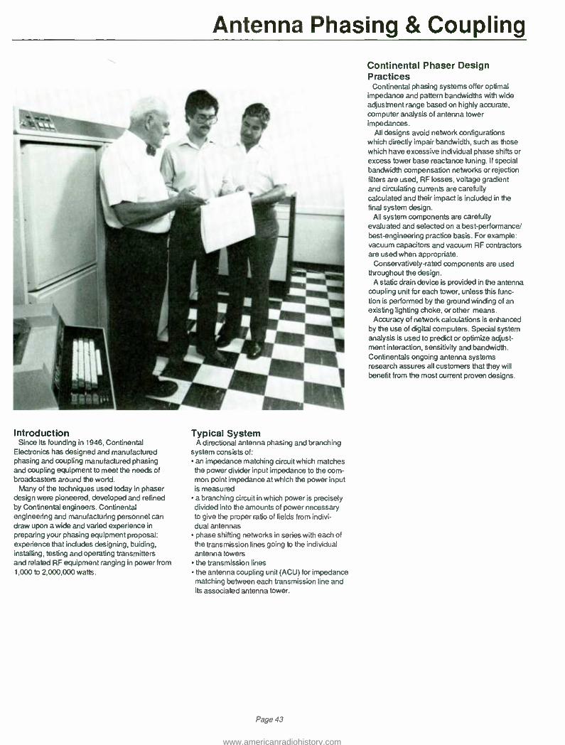
Antenna Phasing & Coupling
Introduction Since its founding in 1946, Continental
Electronics has designed and manufactured phasing and coupling manufactured phasing and coupling equipment to meet the needs of broadcasters around the world.
Many of the techniques used today in phaser design were pioneered, developed and refined by Continental engineers. Continental engineering and manufacturing personnel can draw upon a wide and varied experience in
preparing your phasing equipment proposal: experience that includes designing, buiding, installing, testing and operating transmitters and related RF equipment ranging in power from 1,000 to 2,000,000 watts.
Typical System A directional antenna phasing and branching
system consists of: an impedance matching circuit which matches the power divider input impedance to the com- mon point impedance at which the power input is measured a branching circuit in which power is precisely divided into the amounts of power necessary to give the proper ratio of fields from indivi- dual antennas phase shifting networks in series with each of the transmission lines going to the individual antenna towers the transmission lines the antenna coupling unit (ACU) for impedance matching between each transmission line and its associated antenna tower.
Page 43
Continental Phaser Design Practices
Continental phasing systems offer optimal impedance and pattern bandwidths with wide adjustment range based on highly accurate, computer analysis of antenna tower impedances.
All designs avoid network configurations which directly impair bandwidth, such as those which have excessive individual phase shifts or excess tower base reactance tuning. If special bandwidth compensation networks or rejection filters are used, RF losses, voltage gradient and circulating currents are carefully calculated and their impact is included in the final system design.
All system components are carefully evaluated and selected on a best- performance/ best- engineering practice basis. For example: vacuum capacitors and vacuum RF contractors are used when appropriate.
Conservatively -rated components are used throughout the design.
A static drain device is provided in the antenna coupling unit for each tower, unless this func- tion is performed by the ground winding of an existing lighting choke, or other means.
Accuracy of network calculations is enhanced by the use of digital computers. Special system analysis is used to predict or optimize adjust- ment interaction, sensitivity and bandwidth. Continentals ongoing antenna systems research assures all customers that they will benefit from the most current proven designs.
www.americanradiohistory.com

Antenna Phasing & Coupling
: . o
k . Q `.0,.y t?4"1" ;. ±i
St i(i i 11
a
. ,
. ;, 111V
Continental "Wideband" phaser
Continental engineers have developed a
technique that optimizes the impedance and pattern bandwidths of a phased array. Following is an overview of this technology.
After completion of the initial phaser design, the sideband self and mutual impedances are calculated, based on electromagnetic propagation less than the speed of light. Because sideband parameters are frequency
dependent, different tower electrical heights and spacings exist from those specified for the carrier frequency.
Then, three network models of the towers are calculated: one at carrier, and one at each sideband. The components of each network are placed in the phaser topology, and the whole system is then analyzed by a computer program using admittancy matrix algebra. Component reactances and transmission line lengths are automatically adjusted for fre- quency. The effects of coil Q and transmission line loss are included.
The frequency- sensitive tower impedance model answers two questions which cannot be answered if the tower system's current ratios or operating impedances are assumed to be constant. They are (1) Tower currents at the sidebands. (2) Tower currents at the carrier during the adjustment process.
Obtaining the common -point impedance, VSWR and the tower currents, and the effect each component has on these parameters, enables Continental engineers to prepare an optimum system design. In addition to "widebanding", this technique can be used to study adjustment sensitivity at carrier. It can also be used to give advance indication when a power divider control is more of a phase control and vice -versa Adjustment interaction can be optimized during the design process.
r :.01111111
Page 44
w 11101111111111
www.americanradiohistory.com

Antenna phasing & Coupling IOW), I 10MO 2 TO *II 3 tOMn
I Ì--I SCUM
AWN Y MOW i
a
Typical Network Construction Practice
Interconnecting bus matches associated inductor tubing, or is based on a minimum of 1/8-
inch of diameter per each 10 RMS amps of current. The smallest diameter tubing used is
3/8 -inch. Where flexible connections are required, 1/2 -inch x 20 -mil copper strap is used per 10 RMS amps of current.
The bus size will be selected to minimize or
optimize voltage gradient when a dielectric - heating or ionization probability exists.
All components are removeable from inside the cabinets or from the front surfaces of wall panels. All mounting screws fit in tapped holes or captive nuts, so separate nuts are not required. All hardware is non -ferrous.
t.
y..
mot woos
e
Aluminum and copper parts are irridited, cad- mium or silver plated, or as specified.
A cabinet that is located in a transmitting room
has an interlock circuit, if requested. Epoxy -cast mica capacitors are provided with
flanges for additional heat -sinking, and to faci- litate connection and mounting.
Front panel controls consist of knobs or han- dles, counters and insulated, flexible couplings.
Co -ax outer conductor -U' clamps are provided for transmission line termination unless other termination is specified.
Photo -etched nameplates are used on all phaser cabinet front -panel meters and controls.
Phaser cabinets use overhead grills to allow convection cooling.
f
kk MN.
um sl
- p: ¡: ¡: : '..,1.1t-1
Crial.u.sal&L-LUALLcs.ird.
Page 45
Panels which act as electrical ground are
aluminum, and are bonded to each other with two -inch wide copper straps.
A rolled six foot length of two -inch wide or four -
inch copper strap, depending upon power level,
is provided with each cabinet for connection to
the customer's ground system. The selection of stand -off insulators and
insulation materials is based on strength, low
dielectric dissipation factor and low moisture absorption.
Tubing indicator taps are plated, solid brass to
provide good electrical connection and heat
sinking. Jacks are always positioned so that a plug -in
ammeter will face the operator from a horizontal position.
All co -ax input/output connections are located to customer specifications. If the customer has
no preference, input co -ax connections will be
located at the top of the phaser cabinet, output co -ax connections at the bottom. Control connections will usually be located at the
bottom of all cabinets or panels. ACU inputs will usually be at the lower left: outputs at the upper right.
www.americanradiohistory.com

Antenna Phasing & Coupling r
Typical Control Circuit Design Practices
Continental's standard 28 vdc control circuit is designed for mounting in a 19 -inch rack; either directly in the front panel of the phaser, or externally. Color -coded LEDs give status indications for each tower and phaser cabinet. the momentary push -button switches must be depressed for a full second before switching will begin. This prevents accidental mode change if an operator accidentally depresses a push- button, and assures that the transmitter has adequate time to remove RF output. If desired, the full- second contact can be performed automatically with the addition of two relays.
Remote control capability is built -in to the standard circuit with a "local only" switch for personnel safety during maintenance. A separate remote control panel is available as an option. Control lines can be specified as 28 vdc or 220
vac. Line voltage to the control panel can be specified as 120 vac or 240 vac; 50 or 60 Hz. A'Failsafé circuit will prevent the transmitter
from returning to the air if a mode change is incomplete.
All relays are the same plug -in type. Time delay is accomplished with RC decay networks.
Required Design Data Continental custom designs and manu-
factures antenna phasing and coupling equipment to meet specific broadcasting station requirements. Following is the typical data Continental needs in order to prepare an equipment proposal:
call letters and station location; frequency of operation; operating power (day and night); and mode of operation description of towers; tower manufacturer; type number and tower height; self- supported or guyed; and cross- section dimensions spacing and orientation of all antennas in the array phase relationship and ratios of the radiation fields location of phasing unit type and length of each transmission line.
M
iksol
Continental Electronics AM Antenna Couplers
Standard antenna couplers are available in panel -mount and weatherproof housing con- figurations, for use with Continental 1 kW, 5 kW and 10 kW AM transmitters.
Panel mount couplers come with fully adjustable tee network, input jack, static drain choke, Delta RF ammeter. Tower lighting choke must be ordered as separate item.
Weatherproof couplers come with fully adjustable tee network, input jack, static drain choke, Delta RF ammeter. All components come in weatherproof housing. Tower lighting choke must be ordered as separate item.
Ordering Information Panel Mount Coupler:
1 kW, Type 514AT-1P 5 kW, Type 515AT -1 P
10 kW, Type 516AT-1P Weatherproof Coupler:
1 kW, Type 514AT -1 WP 5 kW, Type 515AT-1WP 10 kW, Type 516AT-1WP
All specifications are subject to change without notice.
Page 46
www.americanradiohistory.com

FM Antennas
Above: G5GPS with Radome. Below: Type 1082 panel antenna.
i I>Mr" istrvir.rom I1 rlY" iilira ':;.{%;;' IÌ.i y, _
i.,lyi!'';A .,N _ _, .. -r / N
I i\v1lP i :%11. . , ; i,lsf/ ;:' ll il : 1_ I i ``
, l' "1, OH, , I rrtúl tt... .. uill í,/ I.l 11~M., - II'I" ' !r 61111117,Q1,
;A. :I I -11_ _
rAt FM Antennas
Continental offers FM broadcasters a wide variety of antennas to meet commercial and educational station requirements: from low power to high power; including circularly and horizontally polarized, and dual polarized directional antenna designs.
G5 Series, Circularly Polarized FM Antennas
The G5 antenna was introduced in 1976.
Since then, it has become the most popular FM antenna available in the United States. It is an electrically sound, mechanically rugged, thoroughly field -proven antenna design. The antenna may be purchased in any number of bays from 1 to 16 (Series A & B).
Each bay level element consists of two segmented series -fed dipoles that form a space -phased, circularly polarized radiator. Each segmented dipole is manufactured using a custom -made Wallace Bending machine. The
dipoles are constructed of 3 -1/8" o.d. brass which provides an excellent element bandwidth as well as protection against corona discharge failure.
The isolated feed point of the two segmented dipoles is pressurized to avoid the effects of atmospheric changes and metal corrosion on the feed point impedance. The insulators are custom -made melamine insulators with machined flange fitting for bolt down "O" ring sealed flange assembly. Each feed point is
silver soldered to the inner conductor inside the driven element; the entire inner conductor assembly of the element is silver plated to
minimize antenna loss. Each individual segmented dipole can be
removed from any bay level element and replaced with a new segmented dipole with no change in the VSWR of the antenna.
Each segmented dipole is constructed with a
Page 47
captive male 3 -1/8" coax 50 ohm inner conductor connector, and is connected to the antenna element using a five bolt pinned flange. This unique construction design assures proper dipole installation.
Electrically, each element in a G5 array is a 50 ohm element at the frequency of operation. When the array is matched, a quarter wave transformation section is designed for each element's feed stem, so that each element adds in shunt with the other elements in the array, with impedance of n x 50 ohms, where n equals the number of elements being added in shunt. This method of matching limits the maximum voltage and current in the antenna array interbay coax while utilizing the advantage of a
50 ohm bay level impedance. The G5 antenna design is very flexible: it
permits side, comer leg or top mounting on any type of tower. All radiating elements and feed stem are constructed of 85 -15 brass; all support brackets and hardware are made of stainless steel.
www.americanradiohistory.com

G5CPS FM Antenna
G5CPS Super Power Circularly Polarized FM Antenna
The brass radiating element has an outside diameter of 3 -1/8 ". The feed point is completely internal with a pressurized environment up to the feed point.
The radiating element is rated at 40 kW, and is limited by the safe average power capability of the 3 -1/8 rigid coax line.
The heavy -wall brass tubing stem can withstand harsh environmental conditions.
Deicers are not recommended in moderate environments because typical VSWR is 1.5:1
or less with 1/2" of radial ice, if the antenna has been field tuned. Heaters for deicers or radomes are available.
All G5CPS antennas use silver -plated inner conductor connectors throughout to reduce losses and heating. Each antenna, supplied with a 6 foot input matching section has 50 -ohm
EIA input. Depending on model type, the input is either a 3 -1/8 inch 50 ohm EIA female input or a 6 -1/8 inch 50 ohm EIA female input.
Once each antenna is completely assembled and factory-tuned to the customers frequency, it is pressure tested at 10 lbs. pressure for one hour to ensure that the antenna is leak -free prior to shipment.
The antenna system feed point is 6 feet below the bottom bay for end fed antennas, and approximately 6 feet below the center of the antenna for center fed antenna systems.
The horizontally polarized horizontal -plane radiation pattern is omnidirectional when pole - mounted atop a tower; a ± 2 dB circularity is
typical when mounted on a 14 inch diameter steel pole. When side -mounted on a tower, the antenna pattern will be affected by the tower structure.
Page 48
Complete antenna pattern measurement services are available on a quotation basis. Horizontal plane relative field patterns are measured on a full scale mock up of a 20 foot section of the customer's tower, including the ladder, coaxial transmission lines, conduits, cables and antenna element. Pattern optimiza- tion for both horizontal and vertical polarization is available for improving the pattern circularity of the antenna -support tower combination. Precision model studies are also available for situations where larger vertical aperatures of the array need to be analyzed.
The G5CPS has a low standing -wave ratio of 1.07:1, or less. ± 200 KHz for a given channel with field trimming. The VSWR at antenna input without field trimming is 1.2:1 for pole mounting atop a tower; 1.5:1 or less when side mounted on a tower.
Multistation operation is possible using a common antenna system due to the excellent bandwidth characteristics of the G5 antenna design. Continental can quote filtering compon- ents required for the diplexing or multiplexing operation. Stations with a frequency separation as large as 4 MHz can be diplexed on a common antenna.
SPECIFICATIONS Frequency Range:
88 to 108 MHz, factory tuned to one frequency
Polarization: Circular (clockwise)
Power Gain: See tables
Azimuthal Pattern: ±2 dB in free space, both horizontal and vertical
Ellipticity: ±3 dB in free space
VSWR at Input (without field tuning): 1.2:1 pole mounting, 1.5:1 or better side mounting
VSWR at input (with field tuning): 1.1:1 or better
(see tables for rest of specifications)
All specifications are subject to change without notice.
www.americanradiohistory.com

G5CPS FM Antenna Series A: 3-1/8" Interbay Une; 3-1/8" Element Stem
No. of Power dB Type 50 Female Power.'
Bays Gain Gain Feed Input Input
Wt.2 In Lbs.
W.L.3 In Lbs.
Wt.4 In Lbs.
W.L.5 In Lbs.
Approx.6 Length In Feet
1 0.4611 -3.3623 End 3 -1/8" 32 kW 114 137 185 354 --
2 0.9971 -0.0128 End 3 -1/8" 32 kW 225 304 376 742 10
2 0.9971 -0.0128 Center 3 -1/8" 39 kW 250 319 385 749 10
2 0.9971 -0.0128 Center 6 -1/8" 64 kW 301 421 436 851 10
3 1.5588 1.9278 End 3 -1/8" 32 kW 336 470 568 1130 20
3 1.5588 1.9278 Center 3 -1/8" 39 kW 361 486 577 1136 20
3 1.5588 1.9278 Center 6 -1/8" 64 kW 412 588 628 1240 20
4 2.1332 3.2903 End 3 -1/8" 32 kW 447 637 759 1518 30
4 2.1332 3.2903 Center 3 -1/8" 39 kW 472 652 768 1525 30
4 2.1332 3.2903 Center 6 -1/8" 64 kW 523 758 819 1631 30
5 2.7154 4.3384 End 3 -1/8" 32 kW 558 804 951 1905 40
5 2.7154 4.3384 Center 3 -1 /8" 39 kW 583 819 960 1911 40
5 2.7154 4.3384 Center 6 -1/8" 64 kW 634 927 1011 2011 40
6 3.3028 5.1888 End 3 -1/8" 32 kW 669 971 1142 2294 50
6 3.3028 5.1888 Center 3 -1/8" 39 kW 694 986 1151 2300 50
6 3.3028 5.1888 Center 6 -1/8" 64 kW 745 1096 1202 2410 50
7 3.8935 5.9034 End 3 -1/8" 32 kW 780 1138 1334 2682 60
7 3.8935 5.9034 Center 3 -1/8" 39 kW 805 1153 1343 2688 60
7 3.8935 5.9034 Center 6 -1/8" 64 kW 856 1265 1394 2800 60
8 4.4872 6.5197 End 3 -1/8" 32 kW 891 1305 1525 3070 70
8 4.4872 6.5197 Center 3 -1/8" 39 kW 916 1320 1534 3076 70
8 4.4872 6.5197 Center 6 -1/8" 64 kW 967 1433 1585 3190 70
9 5.0825 7.0608 Center 3 -1/8" 38 kW 1027 1487 1725 3464 80
9 5.0825 7.0608 Center 6 -1/8" 64 kW 1078 1600 1776 3580 80
10 5.6800 7.5435 Center 3 -1/8" 39 kW 1138 1653 1917 3852 90
10 5.6800 7.5435 Center 6 -1/8" 64 kW 1189 1770 1968 3970 90
11 6.2783 7.9784 Center 3 -1/8" 39 kW 1249 1820 2108 4240 100
11 6.2783 7.9784 Center 6 -1/8" 64 kW 1300 1940 2159 4360 100
12 6.8781 8.3747 Center 3 -1/8" 39 kW 1360 1987 2300 4628 110
12 6.8781 8.3747 Center 6 -1/8" 64 kW 1411 2108 2351 4750 110
Series B: 4 -1/8" Interbay Une; 4-1/8" Element Stem
1 0.4611 -3.3623 End 6 -1/8" 40 kW 159 201 223 421
2 0.9971 -0.0128 End 6 -1/8" 56 kW 297 407 425 847 10
2 0.9971 -0.0128 Center 6 -1/8" 80 kW 336 468 464 908
3 1.5588 1.9278 End 6 -1/8" 56 kW 435 613 627 1273 20
3 1.5588 1.9278 Center 6 -1/8" 112 kW 474 674 666 1337 20
4 2.1332 3.2903 End 6 -1/8" 56 kW 573 818 829 1699 30
4 2.1332 3.2903 Center 6 -1/8" 112 kW 612 879 869 1762 30
5 2.7154 4.3384 End 6 -1/8" 56 kW 711 1024 1031 2125 40
5 2.7154 4.3384 Center 6 -1/8" 112 kW 750 1085 1070 2187 40
6 3.3028 5.1888 End 6 -1/8" 56 kW 849 1229 1233 2551 50
6 3.3028 5.1888 Center 6 -1/8" 112 kW 888 1290 1272 2612 50
7 3.8935 5.9034 End 6 -1/8" 56 kW 987 1435 1435 2997 60
7 3.8935 5.9034 Center 6 -1/8" 112 kW 1026 1496 1474 3037 60
8 4.4872 6.5197 End 6 -1/8" 56 kW 1125 1641 1637 3043 70
8 4.4872 6.5197 Center 6 -1/8" 112 kW 1164 1702 1676 3462 70
9 5.0825 7.0608 Center 6 -1/8" 112 kW 1302 1907 1878 3887 80
10 5.6800 7.5435 Center 6 -1/8" 112 kW 1440 2113 2080 4312 90
11 6.2783 7.9784 Center 6 -1/8" 112 kW 1578 2318 2282 4737 100
12 6.8781 8.3747 Center 6 -1/8" 112 kW 1716 2524 2484 5162 110
Series C: 6-1 /8" Interbay Une; 4 -1/8" Element Stem
1 0.4611 -3.3623 End 6 -1/8" 40 kW 205 260 269 480 --
2 0.9971 -0.0128 End 6 -1/8" 80 kW 410 520 538 960 10
3 1.5588 1.9278 End 6 -1/8" 120 kW 615 780 807 1440 20
4 2.1332 3.2903 End 6 -1/8" 120 kW 820 1040 1076 1920 30
5 2.7154 4.3384 End 6 -1/8" 120 kW 1025 1300 1345 2400 40
6 3.3028 5.1888 End 6 -1/8" 120 kW 1230 1560 1614 2880 50
(1) Power input capability is shown for altitudes up to 2000 feet above mean sea level; derating is required
above 2000 feet. (2) Calculated weight, including brackets. (3) Calculated wind load including brackets, based
on 50/33 Lb /Sq Ft. (4) Calculated weight with Radome and brackets. (5) Calculated wind load with Radome and
brackets, based on 50/33 Lb /Sq Ft. (6) End feed antenna lengths do not include 6 -ft matching transformer.
All specifications are subject to change wfthout notice.
Page 49
www.americanradiohistory.com
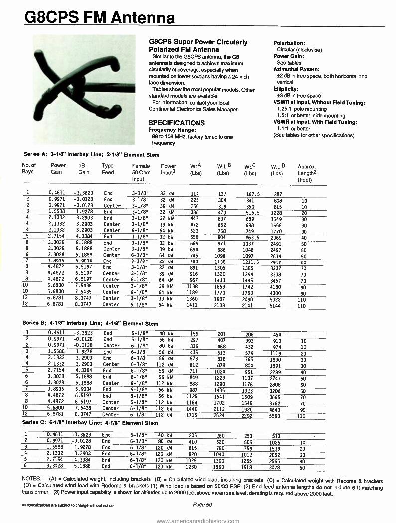
G8CPS FM Antenna
Series A:
G8CPS Super Power Circularly Polarized FM Antenna
Similar to the G5CPS antenna, the G8 antenna is designed to achieve maximum circularity of coverage, especially when mounted on tower sections having a 24 -inch face dimension.
Tables show the most popular models. Other standard models are available.
For information, contact your local Continental Electronics Sales Manager.
SPECIFICATIONS Frequency Range:
88 to 108 MHz, factory tuned to one frequency
3 -1/8" Interbay Une; 3 -1/8" Element Stem
Polarization: Circular (clockwise)
Power Gain: See tables
Azimuthal Pattern: ±2 dB in free space, both horizontal and vertical
Ellipticity: ±3 dB in free space
VSWR at Input, Without Field Tuning: 1.25:1 pole mounting 1.5:1 or better, side mounting
VSWR at Input, With Field Tuning: 1.1:1 or better
(See tables for other specifications)
No. of Bays
Power dB Gain Gain
Type Feed
Female 50 Ohm Input
Power Input3
wt.A
(Lbs) W.L.B (Lbs)
wt.0 (Lbs)
W. L.0 (Lbs)
Approx. Length2 (Feet)
1 0.4611 -3.3623 End 3 -1/8" 32 kW 114 137 167.5 387 2 0.9971 -0.0128 End 3 -1/8" 32 kW 225 304 341 808 10 2 0.9971 -0.0128 Center 3 -1/8" 39 kW 250 319 350 815 10 3 1.5588 1.9278 End 3 -1/8" 32 kW 336 470 515.5 1228 20 4 2.1332 3.2903 End 3 -1/8" 32 kW 447 637 689 1649 30 4 2.1332 3.2903 Center 3 -1/8" 39 kW 472 652 698 1656 30 4 2.1332 3.2903 Center 6 -1/8" 64 kW 523 758 749 1770 30 5 2.7154 4.3384 End 3 -1/8" 32 kW 558 804 863.5 2069 40 6 3.3028 5.1888 End 3 -1/8" 32 kW 669 971 1037 2491 50 6 3.3028 5.1888 Center 3 -1/8" 39 kW 694 986 1046 2497 50 6 3.3028 5.1888 Center 6 -1/8" 64 kW 745 1096 1097 2614 50 7 3.8935 5.9034 End 3 -1/8" 32 kW 780 1138 1211.5 2912 60 8 4.4872 6.5197 End 3 -1/8" 32 kW 891 1305 1385 3332 70 8 4.4872 6.5197 Center 3 -1/8" 39 kW 916 1320 1394 3338 70 8 4.4872 6.5197 Center 6 -1/8" 64 kW 967 1433 1445 3457 70
10 5.6800 7.5435 Center 3 -1/8" 39 kW 1138 1653 1742 4180 90 10 5.6800 7.5435 Center 6 -1/8" 64 kW 1189 1770 1793 4300 90 12 6.8781 8.3747 Center 3 -1/8" 39 kW 1360 1987 2090 5022 110 12 6.8781 8.3747 Center 6 -1/8" 64 kW 1411 2108 2141 5144 110
Series B; 4 -1/8" Interbay Une; 4 -1/8" Element Stem
1 0.4611 -3.3623 End 6 -1/8" 40 kW 159 201 206 454 2 0.9971 -0.0128 End 6 -1/8" 56 kW 297 407 393 913 10 2 0.9971 -0.0128 Center 6 -1/8" 80 kW 336 468 432 974 10 3 1.5588 1.9278 End 6 -1/8" 56 kW 435 613 579 1119 20 4 2.1332 3.2903 End 6 -1/8" 56 kW 573 818 765 1830 30 4 2.1332 3.2903 Center 6 -1/8" 112 kW 612 879 804 1891 30 5 2.7154 4.3384 End 6 -1/8" 56 kW 711 1024 951 2289 40 6 3.3028 5.1888 End 6 -1/8" 56 kW 849 1229 1137 2747 50 6 3.3028 5.1888 Center 6 -1/8" 112 kW 888 1290 1176 2808 50 7 3.8935 5.9034 End 6 -1/8" 56 kW 987 1435 1323 3206 60 8 4.4872 6.5197 End 6 -1/8" 56 kW 1125 1641 1509 3665 70 8 4.4872 6.5197 Center 6 -1/8" 112 kW 1164 1702 1548 3762 70
10 5.6800 7.5435 Center 6 -1/8" 112 kW 1440 2113 1920 4643 90 12 6.8781 8.3747 Center 6 -1/8" 112 kW 1716 2524 2292 5560 110
Series C: 6 -1/8" Interbay Une; 4 -1/8" Element Stem
1 0.4611 -3.3623 End 6 -1/8" 40 kW 205 260 253 513 2 0.9971 -0.0128 End 6 -1/8" 80 kW 410 520 506 1026 10 3 1.5588 1.9278 End 6 -1/8" 120 kW 615 780 759 1539 20 4 2.1332 3.2903 End 6 -1/8" 120 kW 820 1040 1012 2052 30 5 2.7154 4.3384 End 6 -1/8" 120 kW 1025 1300 1265 2565 40 6 3.3028 5.1888 End 6 -1/8" 120 kW 1230 1560 1518 3078 50
NOTES: (A) = Calculated weight, including brackets (B) = Calculated wind load, including brackets (C) = Calculated weight with Radome & brackets (D) = Calculated wind load with Radome & brackets (1) Wind load is based on 50/33 PSF. (2) End feed antenna lengths do not include 6 -ft matching transformer. (3) Power input capability is shown for altitudes up to 2000 feet above mean sea level; derating is required above 2000 feet.
All specifications are subject to change without notice. Page 50
www.americanradiohistory.com
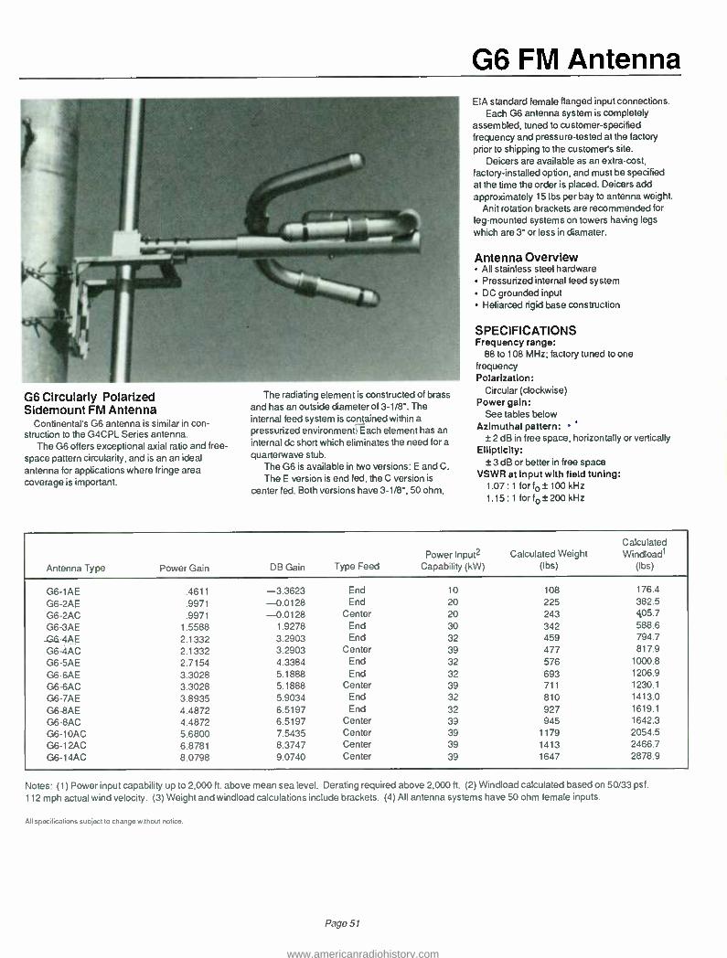
G6 FM Antenna
G6 Circularly Polarized Sidemount FM Antenna
Continental's G6 antenna is similar in con- struction to the G4CPL Series antenna.
The G6 offers exceptional axial ratio and free - space pattern circularity, and is an an ideal antenna for applications where fringe area coverage is important.
The radiating element is constructed of brass and has an outside diameter of 3 -1/8 ". The internal feed system is contained within a
pressurized environment Each element has an internal dc short which eliminates the need for a
quarterwave stub. The G6 is available in two versions: E and C.
The E version is end fed, the C version is
center fed. Both versions have 3 -1/8 ", 50 ohm,
EIA standard female flanged input connections. Each G6 antenna system is completely
assembled, tuned to customer -specified frequency and pressure- tested at the factory
prior to shipping to the customers site.
Deicers are available as an extra -cost, factory- installed option, and must be specified at the time the order is placed. Deicers add approximately 15 lbs per bay to antenna weight.
Anit rotation brackets are recommended for
leg- mounted systems on towers having legs
which are 3" or less in diamater.
Antenna Overview All stainless steel hardware Pressurized internal feed system DC grounded input Heliarced rigid base construction
SPECIFICATIONS Frequency range:
88 to 108 MHz; factory tuned to one frequency Polarization:
Circular (clockwise) Power gain:
See tables below Azimuthal pattern:
± 2 dB in free space, horizontally or vertically Ellipticity:
± 3 dB or better in free space VSWR at Input with field tuning:
1.07:1 for fo±100kHz 1.15:1 for fo±200kHz
Antenna Type Power Gain DB Gain Type Feed Power'nput2
Capability (kW) Calculated Weight
(lbs)
Calculated Windloadl
(lbs)
G6-1AE .4611 -3.3623 End 10 108 176.4
G6-2AE .9971 -0.0128 End 20 225 382.5
G6-2AC .9971 -0.0128 Center 20 243 405.7
G6-3AE 1.5588 1.9278 End 30 342 588.6
G6-4AE 2.1332 3.2903 End 32 459 794.7
G6-4AC 2.1332 3.2903 Center 39 477 817.9
G6-5AE 2.7154 4.3384 End 32 576 1000 8
G6-6AE 3.3028 5.1888 End 32 693 1206.9
G6-6AC 3.3028 5.1888 Center 39 711 1230.1
G6-7AE 3.8935 5.9034 End 32 810 1413.0
G6-8AE 4.4872 6.5197 End 32 927 1619.1
G6-8AC 4.4872 6.5197 Center 39 945 1642.3
G6-10AC 5.6800 7.5435 Center 39 1179 2054.5
G6-12AC 6.8781 8.3747 Center 39 1413 2466.7
G6-14AC 8.0798 9.0740 Center 39 1647 2878.9
Notes: (1) Power input capability up to 2,000 ft. above mean sea level. Derating required above 2,000 ft. (2) Windload calculated based on 50/33 psf.
112 mph actual wind velocity. (3) Weight and windload calculations include brackets. (4) All antenna systems have 50 ohm female inputs.
All specifications subject to change without notice.
Page 51
www.americanradiohistory.com
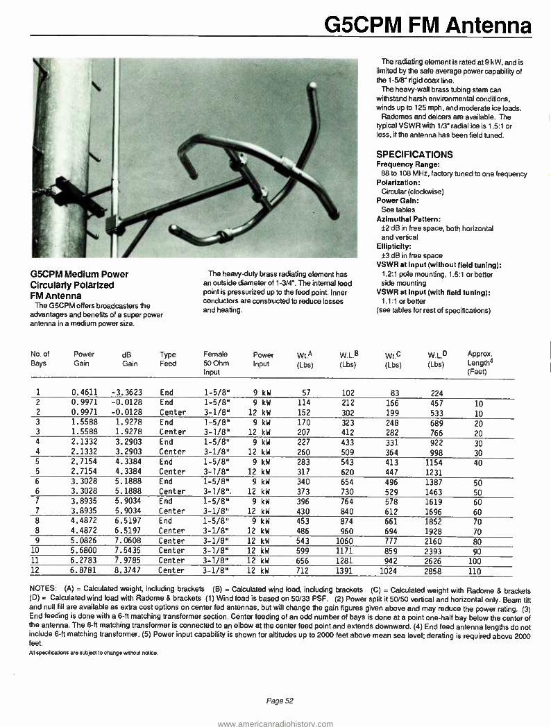
G5CPM FM Antenna
G5CPM Medium Power Circularly Polarized FM Antenna
The G5CPM offers broadcasters the advantages and benefits of a super power antenna in a medium power size.
The heavy -duty brass radiating element has an outside diameter of 1 -3/4'. The internal feed point is pressurized up to the feed point. Inner conductors are constructed to reduce losses and heating.
The radiating element is rated at 9 kW, and is limited by the safe average power capability of the 1 -5/8' rigid coax line.
The heavy -wall brass tubing stem can withstand harsh environmental conditions, winds up to 125 mph, and moderate ice loads.
Radomes and deicers are available. The typical VSWR with 1/3 radial ice is 1.5:1 or less, if the antenna has been field tuned.
SPECIFICATIONS Frequency Range:
88 to 108 MHz, factory tuned to one frequency Polarization:
Circular (clockwise) Power Gain:
See tables Azimuthal Pattern:
±2 dB in free space, both horizontal and vertical
Ellipticity: ±3 dB in free space
VSWR at input (without field tuning): 1.2:1 pole mounting, 1.5:1 or better side mounting
VSWR at Input (with field tuning): 1.1:1 or better
(see tables for rest of specifications)
No. of Bays
Power Gain
dB Gain
Type Feed
Female 50 Ohm Input
Power Input
Wt.A (Lbs)
W.L.B (Lbs)
Wt.0 (Lbs)
W.L.O (Lbs)
Approx. Length4 ( Feet)
1 0.4611 -3.3623 End 1 -5/8" 9 kW 57 102 83 224 2 0.9971 -0.0128 End 1 -5/8" 9 kW 114 212 166 457 10 2 0.9971 -0.0128 Center 3 -1/8" 12 kW 152 302 199 533 10 3 1.5588 1.9278 End 1 -5/8" 9 kW 170 323 248 689 20 3 1.5588 1.9278 Center 3 -1/8" 12 kW 207 412 282 766 20 4 2.1332 3.2903 End 1 -5/8" 9 kW 227 433 331 922 30 4 2.1332 3.2903 Center 3 -1/8" 12 kW 260 509 364 998 30 5 2.7154 4.3384 End 1 -5/8" 9 kW 283 543 413 1154 40 5 2.7154 4.3384 Center 3 -1/8" 12 kW 317 620 447 1231 6 3.3028 5.1888 End 1 -5/8" 9 kW 340 654 496 1387 50 6 3.3028 5.1888 Center 3 -1/8 ". 12 kW 373 730 529 1463 50 7 3.8935 5.9034 End 1 -5/8" 9 kW 396 764 578 1619 60 7 3.8935 5.9034 Center 3 -1/8" 12 kW 430 840 612 1696 60 8 4.4872 6.5197 End 1 -5/8" 9 kW 453 874 661 1852 70 8 4.4872 6.5197 Center 3 -1/8" 12 kW 486 960 694 1928 70 9 5.0826 7.0608 Center 3 -1/8" 12 kW 543 1060 777 2160 80
10 5.6800 7.5435 Center 3 -1/8" 12 kW 599 1171 859 2393 90 11 6.2783 7.9785 Center 3 -1/8" 12 kW 656 1281 942 2626 100 12 6.8781 8.3747 Center 3 -1/8" 12 kW 712 1391 1024 2858 110
NOTES: (A) = Calculated weight, including brackets (B) = Calculated wind load, including brackets (C) = Calculated weight with Radome & brackets (D) = Calculated wind load with Radome 8 brackets (1) Wind load is based on 50/33 PSF. (2) Power split it 50/50 vertical and horizontal only. Beam tilt and null fill are available as extra cost options on center fed antennas, but will change the gain figures given above and may reduce the power rating. (3) End feeding is done with a 6-ft matching transformer section. Center feeding of an odd number of bays is done at a point one -half bay below the center of the antenna. The 6 -ft matching transformer is connected to an elbow at the center feed point and extends downward. (4) End feed antenna lengths do not include 6 -ft matching transformer. (5) Power input capability is shown for altitudes up to 2000 feet above mean sea level; derating is required above 2000 feet. All specifications are subject to change without notice.
Page 52
www.americanradiohistory.com

G4CPH FM Antenna
G4CPH High Power Circularly Polarized FM Antenna
The G4CPH is a rugged, heavy -duty design capable of handling powers from 5 kW (single bay) to 40 kW (eight or more bays). The antenna may be purchased in any number of bays from 1
to 16. The antennas are end fed in combinations from one to eight bays. In center fed anntenna arrays, the center fed "T" input is located one half bay spacing below the center of the array if
the array consists of an odd number of bays.
Antennas of one to eight bays are end fed with a 6 foot matching section connected to the bottom bay.
The rings of the antenna are mounted on 3 -1/8" transmission line with a 3 -1/8" input flange on standard antennas. Antennas that are to have 40 kW input are provided with a 6-1/8" flange and center feed block (at extra cost). 3" dia- meter Corona balls are provided at the outer extremity of the arms of each bay of the antenna. The antenna is designed to withstand wind velocities to 150 miles per hour.
Factory- installed deicers are available in
powers of 300 and 500 watts per bay. Specify 120- or 230 -volt operation when ordering. Shielded interbay heater cable and junction boxes are supplied as a part of the heater system. Heater weight, including junction boxes and cable, is 7 lb. per bay. Heaters are field replaceable.
Special power splits, other than 50/50 (vertical
and horizontal), beam tilt and'or null till are
available at extra cost. Radomes are also available to reduce the
effect of ice on the VSWR of the antenna
SPECIFICATIONS Frequency Range:
88 to 108 MHz, factory tuned to one frequency Polarization:
Circular (clockwise) Power Gain:
See tables Azimuthal Pattern:
±2 dB in free space, both horizontal and vertical
Ellipticity: ±3 dB in free space
VSWR at Input (without field tuning): 1.25:1 pole mounting, 1.5:1 or better side mounting
VSWR at Input (with field tuning): 1.1:1 or better
(see tables for rest of specifications)
All specA cations are subject to change without notice.
Type Power Gain dB Gain Field Gain
Input Power Rating kW
Approx. Length (m) R
Weight (Including Brackets) (kg) lb
Wind Load Based on 244 161 kg sq.m (5033 Ibisq ft) (kg) lb
Weight ( With Radomes Incl. Brackets) (kg) lb
Wind Load With Radomes Based on 244 161 kg /sq.m (50/33 Ib /sq RI (kg) lb Horiz Vert Horiz Vert Horiz Vert
G4CPH-1 0.4611 0.4611 - 3.3623 - 3.3623 0.6790 0.6790 5.0 - (38) 84 (65) 144 (47) 104 (120) 265 G4CPH-2 0.9971 0.9971 - 0.0128 - 0.0128 0.9985 0.9985 10 (31 10 (83) 184 (1441 318 (1021 224 (2541560 G4CPH-3 1.5588 1.5588 1.9278 1.9278 1.2485 1.2485 15 (6) 20 (124) 274 ( 223) 492 (152) 334 (388) 855 G4CPH-4 2.1332 2.1332 3.2903 3.2903 1.4605 1.4605 20 (9( 30 (165) 364 (302) 666 (2011 444 (522) 1150 G4CPH-5 2.7154 2.7154 4.3384 4.3384 1.6478 1.6478 25 (121 40 1206) 454 1381) 840 (251( 554 (655 ( 1445 G4CPH-6 3.3028 3.3028 5.1888 5.1888 1.8174 1.8174 30 051 50 ( 2471 544 (460) 1014 13011 664 (789) 1740 G4CPH-7 3.8935 3.8935 5.9034 5.9034 1.9732 1.9732 35 (181 60 1288) 634 (538) 1187 (3511 774 (923) 2034 G4CPH-8 4.4872 4.4872 6.5197 6.5197 2.1183 2.1183 40 (21) 70 (328) 724 1617) 1361 (4011 884 (1056) 2329 G4CPH-9 5.0826 5.0826 7.0608 7.0608 2.2545 2.2545 40 124) 80 1 3791 835 (729) 1608 (4601 1015 (1223) 2697 G4CPH-10 5.6800 5.6800 7.5435 7.5435 2.3833 2.3833 40 (27) 90 (4201 925 (808) 1782 (510) 1125 (1357) 2992 G4CPH-11 6.2783 6.2783 7.9785 7.9785 2.5057 2.5057 40 (30) 100 (460) 1015 (887) 1956 (560) 1235 (14911 3287 G4CPH-12 6.8781 6.8781 8.3747 8.3747 2.6226 2.6226 40 (34) 110 (501) 1105 (966) 2130 (610) 1345 (1625) 3582 G4CPH-13 7.4785 7.4785 8.7381 8.7381 2.7347 2.7347 40 (37) 120 (542) 1195 (1045) 2303 (6601 1455 (1758) 3876 G4CPH-14 8.0800 8.0800 9.0741 9.0741 2.8425 2.8425 40 (40) 130 (583) 1285 11124) 2477 (710) 1565 (18921 4171 G4CPH-15 8.6818 8.6818 9.3861 9.3861 2.9465 2.9465 40 (431 140 (6241 1375 (1202) 2651 (760) 1675 (20261 4466 G4CPH-16 9.2846 9.2846 9.6776 9.6776 3.0471 3.0471 40 (46) 150 (665) 1465 (1281) 2825 (810) 1785 (2160(4761
All antenna brackets are stainless steel. All weights given include brackets, interbay line, and transformer section. Factory- installed deicers are avail- able using either 300 watts or 500 watts per bay. Specify 120 or 230 volts. Heater elements are replaceable in the field. Shielded interbay heater cable and junction boxes are supplied. Heater weight, including junction boxes and interbay cable, is 6 lb (2.7 kg) additional per bay.
Page 53
www.americanradiohistory.com

G4CPL FM Antenna
G4CPL Low Power Circularly Polarized FM Antenna The general construction of the G4CPL FM
Antenna is the same as the G4CPM medium power version.
A quarter -wave stub, which places the antenna at dc ground potential for added protection against lightning strikes, is an integral part of the G4CPL Antenna design.
The rings of the antenna are mounted on 1 -5/8' line and are end fed. A 6 ft. matching transformer extends below the lower bay and terminates in a 1 -5/8' EIA, 50 ohm flange.
Factory- installed deicers are available in
powers of 300 and 500 watts per bay. Specify 120 or 230 volt operation when ordering. Shielded interbay heater cable and junction boxes are supplied as a part of the heater system. Heater weight, including junction boxes and cable, is 6 lb per bay. Heaters are field replaceable.
No special power splits other than 50/50, nor b'am tilt nor null fill are offered for this antenna. Radomes are also available.
SPECIFICATIONS Frequency Range:
88 to 108 MHz, factory tuned to one frequency Polarization:
Circular (clockwise) Power Gain:
See tables Azimuthal Pattern:
±2 dB in free space, both horizontal and vertical
Ellipticity: ±3 dB in free space
VSWR at Input (without field tuning): 1.25:1 pole mounting, 1.5:1 or better side mounting
VSWR at Input (with field tuning): 1.1:1 or better
(see tables for rest of specifications)
Wind Load Based on
Wind Load With Radomes
Input Power Approx.
Weight (Including
244 161 kgsq.m
Weight With Radomes
Based on 244 161 kgsq.m
Power Gain dB Gain Field Gain Rating Length Brackets' (50 33 lb. sq ft( Incl. Brackets( (5033 lb sq ft( Type Horiz Vert Horiz Vert Horiz Vert kW (m) ft (kg( ft (kgf ft (kg( ft (kg) ft
G4CPL-1 0.4611 0.4611 -3.3623 - 3.3623 0.6790 0.6790 3 - 1161 36 1 341 74 ( 24) 54 1 731 161
G4CPL -2 0.9971 0.9971 - 0.0128 - 0.0128 0.9985 0.9985 6 (3) 10 ( 351 77 ( 47) 104 ( 52) 115 (153 ( 338
G4CPL -3 1.5588 1.5588 1.9278 1.9278 1.2485 1.2485 7.5 (6) 20 (54) 118 ( 115( 254 1781 172 (234( 515
G4CPL -4 2.1332 2.1332 3.2903 3.2903 1.4605 1.4605 7.5 1101 30 (72) 159 (156( 344 (105( 231 (314( 693
G4CPL -5 2.7154 2.7154 4.3384 4.3384 1.6478 1.6478 7.5 112) 40 ( 91) 200 (197) 434 (1321 290 ( 385) 870
G4CPL -6 3.3028 3.3028 5.1888 5.1888 1.8174 1.8174 7.5 (15) 50 1091 241 2381 524 (1581 349 (475) 1047
G4CPL -7 3.8935 3.8935 5.9034 5.9034 1.9732 1.9732 7.5 (18) 60 ( 128) 282 (279) 614 (185) 408 ( 555) 1224
G4CPL -8 4.4782 4.4872 6.5197 6.5197 2.1183 2.1183 7.5 ( 211 70 '147) 323 ( 3 19 1 704 ( 212) 467 ( 636) 1402
All antenna brackets are stainless steel. All weights given include brackets, interbay line, and transformer section. Factory -installed deicers are available using either 300 watts or 500 watts per bay. Specify 120 or 230 volts. Heater elements are replaceable in the field. Shielded interbay heater cable and junction boxes are supplied. Heater weight, including junction boxes and interbay cable, is 6 lb (2.7 kg) additional per bay.
Page 54
www.americanradiohistory.com

G4D FM Antenna
G4D Dual Polarized Directional FM Antenna
The G4D antenna is designed and built primarily for the FM station located along an ocean coast or in mountainous areas where there is a need to radiate power in a 180 -degree pattern rather than waste energy over water or into a mountainside. Or, where the licensing authority such as the FCC will allow the use of a
directional antenna to meet some special requirement.
The design of the G4D antenna is based on the elements being pole mounted. Normally the antenna is quoted with the pole included, but it can also be offered without the pole. In that case, exact details of the customer -supplied pole will be required before fabrication begins.
The G4D consists of vertical and horizontal
Type G4D-() Dual Polarized Directional FM Antenna
elements that are 3 -1/8" in diameter and made of brass to resist the effects of weathering. The size of the elements contributes to the
unusually wide bandwidth of this antenna. Typically, the bandwidth is 5 Mhz between the 1.5:1 VSWR points. And, because of this very wide bandwidth, the G4D does not require deicing provisions except under the most severe conditions. G4D antennas have been operated with up to 1/2 of an inch of radial ice
without causing serious detuning. Radomes are recommended in severe environments.
Because it is a directional antenna, each G4D is pattern tested on the antenna range prior to
shipment. Pattern documentation is provided with the antenna to meet the filing requirements of the FCC. Because the antenna and the mounting pole make up an integral unit, field tuning is seldom required.
Typical patterns which can be achieved through the use of a G4D antenna are shown on
the following page. The gain figures shown are for the particular pattern achieved and can therefore vary depending upon a station's requirements.
When ordering a G4D antenna, the following information must be supplied: maximum ERP authorized, true azimuth orientation, radiated power limitations and their true orientation, transmission line efficiency or transmission line type and length, and the power output of the transmitter with which the antenna will be used.
As with all Continental Electronics FM anten- nas, the G4D is designed to be pressurized with either dry air or nitrogen. A positive pressure of 3 to 5 pounds should be maintained after the line and antenna have been initially
purged to remove moisture.
Pattern 1 Pattern 2 Pattern 3 Pattern 4
Number of Bays
Maximum Power Gain Horiz Vert
Maximum Power Gain Horiz Vert
Maximum Power Gain Horiz Vert
Maximum Power Gain Horiz Vert
1 0.81 0.72 0.79 0.70 0.76 0.70 0.72 0.69
2 1.74 1.53 1.70 1.49 1.63 1.50 1.54 1.47
3 2.71 2.39 2.64 2.:3:3 2.54 2.:34 2.39 2.29
4 3.70 3.26 3.61 3.18 3.47 3.19 3.26 3.13
5 4.71 4.14 4.58 4.03 4.40 4.05 4.14 3.98
6 5.71 5.03 5.56 4.90 5.35 4.92 5.03 4.83
7 6.73 5.92 6.55 5.77 6.29 5.79 5.92 5.68
8 7.75 6.82 7.55 6.64 7.25 6.67 6.82 6.54
NOTE: The listed power gain figures are approximate only, but are useful as a guide in determining the number of bays required. The gain figures will vary with the pattern shape, and the exact gain figures are determioned when the final antenna pattern is achieved. The power gain for the vertical polarization component may be less than the horizontal polarization component since it will differ a bit in shape. The RMS of the vertically polarized component cannot exceed the RMS of the horizontally polarized component. The vertically polarized component cannot exceed the horizontally polarized component at any azimuth.
All specifications are subject to change without notice.
Page 55
www.americanradiohistory.com

G4D FM Antenna G4D -( ) Dual Polarized Directional FM Antennas
No. of Bays
Input Power Rating
Input Flange
Length In Feet
Pole Outer Diameter
Pole Wt. In Lbs
Polet Wind Ld In Lbs
Antenna Wt. In Lbs
Antenna3 Antenna4 Antennas Wind Ld Wt. Wind Ld In Lbs In Lbs In Lbs
Height6 Electrical Center
1 A 12 kW 1-5/8" 25 8-5/8" 1088 1363 280 418 337 666 22
1 B 40 kW 3-1/8" 25 8-5/8" 1088 1363 280 418 337 666 22
2 A 12 kW 1-5/8" 35 8-5/8" 1526 1955 479 855 593 1351 26.4
2 B 40 kW 3-1/8" 35 8-5/8" 1526 1955 479 855 593 1351 26.4
3 A 12 kW 1-5/8" 45 10-3/4" 1975 2812 678 1293 849 2037 31
3 8 40 kW 3-1/8" 45 10-3/4" 1975 2821 678 1293 849 2037 31
4 A 12 kW 1-5/8" 55 10-3/4" 3216 3462 877 1731 1105 2723 35.3
4 B 40 kW 3-1/8" 55 10-3/4" 3216 3462 877 1731 1105 2723 35.3 5 A 12 kW 1-5/8" 65 12-3/4" 4761 4474 1076 2168 1361 3408 39.7
5 B 40 kW 3-1/8" 65 12-3/4" 4761 4474 1076 2168 1361 3408 39.7 6 A 12 kW 1-5/8" 75 14" 5963 5441 1275 2606 1617 4094 44.2
6 B 40 kW 3-1/8" 75 14" 5963 5441 1275 2606 1617 4094 44.2
7 A 12 kW 1-5/8" 85 14" 7670 6182 1474 3044 1873 4780 48.6
7 B 40 kW 3-1/8" 85 14" 7670 6182 1474 3044 1873 4780 48.6
8 A 12 kW 1-5/8" 95 14" * 8896 6633 1673 3481 2129 5465 53
8 B 40 kW 3-1/8" 95 14" * 8896 6633 1673 3481 2129 5465 53
(1) All 1 -5/8" flanges are male; all 3 -1/8" flanges are female. (2) Based on 50 Lbs /Sq. Ft. with 1/2" radial ice on pole. (3) Based on 50/33 Lbs /Sq. Ft. (112 mph wind). (4) With Radomes. (5) With Radomes; based on 50/33 Lbs /Sq. Ft. (6) Above tower top at approximately 89.0 MHz. 'Eight bay antennas require 2 -ft section of 16" pole at base of pole structure.
e0° 270°
120° 240"
e0° 300°
90° 270°
120° 240°
330° 30°
Pattern 1
o
0 30° 330°
300^ 50° 60° 300'
270° 90° 90° 270°
240° 120° 120° 240°
30°
Pattern 2
o o
330°
150° 210° 150° 150° 210° 210° 180° 150° 210° 180° 150°
Pattern 3 Pattern 4
30° o 330° 30° o 330° 330° o 30° 330° o 30°
300° eo° 60° 300°
270° 90° 90° 270°
240° 120° 120° 240°
150° 100° 210° 150° 150° 210° 210° 190° 150° 210° 180° 150°
All specifications are subject to change without notice.
Page 56
www.americanradiohistory.com

Antenna System Accessories
Ice Warning System The Rosemount ice warning system consists
of a controller and an ice detector'. Most ice warning and heater control systems
are operated by a thermostat device; thus, antenna heaters are energized whenever the temperature drops below approximately 35 °F (1.7 °C). Statistically, the probability of icing seldom exceeds 3 percent, even during the winter months. The remaining 97 percent of the time, antenna heater power activated by a
thermostatic device provides expensive and unnecessary insurance against icing.
The Rosemount system is designed to reduce antenna de -icing costs and to fully automate antenna de -icing systems.
The Rosemount system will detect ice and energize antenna heaters only when ice is
physically present, but before ice accumulation can reduce antenna performance. The Rosemount system thus provides reliable, completely automated antenna icing protection at a fraction of the cost for continuous heater operation whenever the ambient temperature is
below approximately 35 °F (1.7°C) In many cases, the Rosemount system will pay for itself in less than one icing season.
Micro -Trak 2580 Antenna Heater Control System
The 2580 senses ambient atmospheric conditions and controls power to the element heaters in FM, TV, and other electrically heated antenna arrays. The system provides aural and visual indication of status, monitors the condition of the heater elements, and provides an alarm in the event of a failure. The 2580 reduces operational costs by continually sensing atmospheric conditions, thus restricting heater turn -on to ice- causing conditions: freezing temperatures and precipitation. The 2580 system consists of four basic components: 2580 Control Unit, 2580 -TT Temperature Sensing Unit, 2580 -PD Precipitation Detector, and the 2580 -HF Heater Failure Sense Transformer. The system has been field- tested in depth to optimize design and ensure performance and reliability. Option- al accessories (Remote Display Output Circuit, Remote Display Panel, Calibration Box, Power Contactors and Enclosures, and Slow Start Kit) are available. Size:
Standard 3-1/2' (8.8 cm) x 19' (48.2 cm) Rack Panel x 8' (20.3 cm) D
2580 Control Unit 2580 -TT NPN Temperature Sensing Unit 2580 -PD NPN Precipitation Detector 2580 -HF NPN Heater Failure Sense
Transformer
Page 57
Beacon Light Control Fisher - Pierce 63305 -DB beacon light control
mounts in a standard commercial socket. It
automatically controls broadcast tower lights directly, or with auxilliary contractors. An
adjustable potentiometer allows adjustment for operation from 0 to 50 footcandles. Power requirements:
105 to 130 volts: 50/60 Hz Built -in load contractor:
Single -pole, single throw, double break; 30 amps
Load rating: 3000 watts
All specifications are subject to change without notice.
www.americanradiohistory.com

Antenna Transmission Line Foam-Dielectric 1- 1/4r " and 1 -5/8"
Foam 1 -1/4" Connectors Foam 1 -5/8" Connectors
Andrew Andrew Andrew Andrew
Standard Cable, Standard Jacket LDF6 -50 LDF7 -50A
Standard Cable, Fire -Retardant Jacket 41690 -46 41690 -23
1 -5/8" EIA Flange, no gas barrier at interface 1 L46R 2 L47R
7/8" EIA Flange, no gas barrier at interface 1 L46S 2 L47S
"F" Flange (male) 3 L46F L47F
"F" Flange (female) 4 Not available 201942
N Plug (male), mates with UG -23 L46W 2 Not available
N Jack (female), mates with UG -21 L46N 2 L47N
LC Plug (male), mates with UG -352 L46M 2 L47M
LC Jack (female), mates with UG -154 L46L 2 L47L
7/16 DIN male L46DM 2 L47DM
7/16 DIN female L46DF 2 L47DF
Splice L46Z L47Z
1 -5/8" End Terminal 5 2061 2061
1 -5/8" Gas Barrier 6 1261B 1261B
Hanger Kit 42396A -1 42396A -1
Hoisting Grip 24312A 24312A
Grounding Kit 2049893 2049893
Reattachment Kit 34767A -43 34767A -43
Notes: (1) Includes inner connector; (2) Includes pressure port for pressurization of antenna feed; (3) For attachment to "F" series antennas; (4) For connection to jumper cable; (5) For strap connection to center conductor, includes inner connector; (6) For connection to pressurized line, includes inner connector.
All specifications are subject to change without notice.
The LDF6 -50 and LDF7 -50A HELIAX foam - dielectric cables are designed for use as feeders for antennas used in the AM and FM broadcast bands. LDF6 -50 provides a pressure path through the tubular inner conductor. All L46 connectors (except L46F) provide a pressure port on the connector body for completing a pressure path to air -dielectric feed antennas and other pressurized components.
Ideal for low power FM applications, LDF6 -50 is the first and only currently available foam - dielectric cable allowing a pressurized antenna without a pressurized line.
Page 58
www.americanradiohistory.com

Rigid 1 -5/8r" Antenna Transmission Line
Rigid: 1 -5/8"
Andrew Cablewave Myatt Phelps -Dodge Dielectric
20-Ft. Une Section, flange both ends 561 920124 201 -001 1- 158 -50 DC- 275-00
20-Ft. Une Section, flanged one end 561 -11 920218 201-006 2- 158 -50 Not Available
20 -Ft. Line Section, unflanged 561 -21 920222 201- 004 3- 158-50 DC265-002
Elbow,90- degree 1061 920226 201 -020 4-158-50 DC275 -017
Elbow, 45- degree Not Available 920230 201-030 5- 158-50 DC275 -020
Flange, fixed 18631 920288 201-008 13-158 DC275-006
Flange, swivel 18041 920284 201 -009 18- 158 -50 Not Available
Flange, field (Soft sold.) 1561A Not Available 201 -013 Not Available DC275 -014
Flange, unpressurized Not Available 920304 Not Available 11 -158 DC260 -015
Inner Connector 34660 612874 201 -010 12- 158 -50 DC275 -011
Inner Connector for unflanged line only Not Available 920300 201 -014 27- 158 -50 DC365-007
Gas Barrier 1261B 920238 201 -050 7- 158-50 DC275-005
End Terminal 2061 920253 201- 080 20- 158 -50H Not Available
Hardware Set 11381 -2 920273 201 -012 26 -158 DC270 -012
O Ring Gasket 10683-406 520681 -011 201 -011 14 -158 DC270
Fixed Hanger 13924 920303 201 -142 -1 51 -158 DC270-034
Spring Hanger 14378 920311 201 -042 -3 91 -158 DC270 -036
Horizontal Hanger 3911 920319 201 -042 -12 71 -158 DC270 -030
Round Member Adaptor 13550 514542-003 Not Available Use Cablewave Use Cablewave
Angle Adaptor 13555A 920167-002 Not Available Use Cablewave Use Cablewave
Wall Feed Thru 3901 920322 201 -042 -5 111 -158 DC270 -028
Reducer, 1 -5/8- TO 7/8- 1860A 920249 201 -064 17- 158 -50 DC275-060
Reducer, 3 1/8" to 1 -5/8- 1861 920250 301 -064 17- 318 -50 DC375-060
Lateral Brace 3921 920316 201 -042 -8 131 -158 Not Available
M specifications are subject to change without notice.
Page 59
www.americanradiohistory.com

Antenna Transmission Line Rigid:3 -1/8
Rigid 3 -1/8"
Andrew Cablewave Myatt Phelps -Dodge Dielectric
20-Ft. Line Section, flanged both ends 562A 920215 301-001 1-318-50 DC375 -002
20-Ft. Line Section, flanged one end 562A -11 920219 301-006 2 -318-50 Not Available
20-FL Line Section, unflanged 562A -21 920223 301-004 3-318-50 DC365 -002
Elbow, 90- Degree, flanged 1062 920227 301-020 4-318-50 DC375-017
Elbow, 45- Degree 1162 920321 301-030 5-318-50 DC375 -020
Flange, fixed 15840 920289 301-008 13 -318 DC375 -006
Flange, swivel 18200 920285 301-009 18 -318 -50 DC3601 -015
Flange, field (soft solder) 1562A Not Available 301 -013 Not Available DC375-014
Flange, unpressurized Not Available 920305 301 -014 11 -318 DC360-015
Inner Connector 30079 622720 301 -010ML 12- 318-50 DC375 -011
Inner Connector for unflanged line only Not Available 920301 301 -010ML 27- 318-50 DC365 -007
Gas Barrier 1262B 920239 301 -050 7-318-50 DC375 -005
End Terminal 2062 920254 301-080 20- 318 -50H Not Available
Hardware Set 11381 -3 920274 301 -012 26 -318 DC370-012
"0" Ring Gasket 10683 -405 Use Phelps -Dodge 301 -011 14 -318 DC370-010
Fixed Hanger 13927 920309 301 -042 -1 51 -318 DC370 -034
Spring Hanger 13925 920312 301 -042 -3 91 -318 DC370 -036
Horizontal Hanger 3912 920320 301 -042 -9 71 -318 DC370-028
Round Member Adaptor 31670-3 514542 -003 Use Cablewave Use Cablewave Use Cablewave
Angle Adaptor 3176M 920167 -004 Use Cablewave Use Cablewave Use Cablewave
Wall Feed Thru 3902 920323 301 -042 -5 111 -318 DC370-028
Reducer, 6-1/8" to 3 -1/8" 1872 920 -251 601-064 17- 618 -50 DC675-061
Reducer, 3-1/8" to 1 -5/8" 1861 920250 301-064 17- 318 -50 DC375 -060
Lateral Brace 3922 920317 301 -042 -8 131 -318 DC370 -038
All specifications are subject to change without notice.
Page 60
www.americanradiohistory.com

Rigid:4 -1/16" Antenna Transmission Line
Rigid: 4- 1/16"
Andrew Cablewave Myatt Phelps -Dodge Dielectric
20-Ft. Line Section, flanged both ends ACA -450 -1 Not Available 401-001 Not Available 475 -002
20 -Ft. Line Section, flanged one end only ACX -450 -4 N/A Not Available N/A Not Available
20-Ft. Line Section, unflanged ACX -450 -5 N/A 401-004 N/A 465 -002
Elbow, 90- Degree ACX- 450-10 N/A 401 -020 N/A 475-017
Elbow, 45-Degree Not Available N/A Not Available N/A 475-020
Flange, fixed ACX -450-28 N/A 401-008 N/A 475 -006
Flange, swivel ACX- 450-27 N/A 401-009 N/A 460 -013
Flange, field (soft solder) Not Available N/A 401 -013 N/A 470 -014
Flange, unpressurized Not Available N/A 401 -014 N/A 460 -015
Inner Connector ACX -450 -20 N/A 401 -010 WA 475-011
Inner Connector for unflanged line only Not Available N/A use 401 -010 WA 465 -007
Gas Barrier ACX -450 -16 N/A 401 -050 N/A 475 -005
End Terminal Not Available N/A Not Available N/A Not Available
Hardware Set ACX -450 -21 N/A 401 -012 WA 470-012
NY Ring Gasket Not Available N/A 401 -011 N/A 470-010
Fixed Hanger ACX- 450 -21 N/A 401-042 -1 N/A 470-034
Spring Hanger ACX -450 -11 N/A 401 -042 -3 N/A 470 -036
Horizontal Hanger ACX- 450-15 N/A Not Available N/A Not Available
Round Member Adaptor cw.....514542-004 N/A 514542-004 N/A Not Available
Angle Adapbr c.w..920167 -004 N/A c.a....920167 -004 N/A Not Available
Wall Feed Thru *m401-042-5 N/A 401 -042 -5 N/A 470-028
Reducer, 6 -1 /8- to 4 -1 /16" Not Available N/A 401-084 N/A 675 -060
Lateral Brace ACX450 -11 N/A 401 -042 -8 N/A 470 -038
Coupling, unpressurized ry.r401 -017 N/A uy.r 401 -017 N/A .y..401 -017
All specifications are subject to change without notice.
Page 61
www.americanradiohistory.com

Antenna Transmission Line Air Dielectric: 7/8" and 1 -5/8"
Air Dielectric: 7/8" Air Dielectric: 1 -5/8"
Andrew Cablewave Andrew Cablewave
Line Type Number 1-IJ5 -50 FCC78 -50J HJ7 -50A HCC- 158 -50J
Flange, gas pass EIA 75AR 738259 87R 738314
Flange, gas barrier EIA 75AG 738256 87G 738303
Flange, LC plug 75AM 738254 87L (female) 738302 (female)
Flange, N -plug 75ÁN 738251 87N 738301 (female
End Terminal 75AT 738258 87T 738306
Gas Barrier 1260A 920237 1261B 920238
Splice 75AZ 738257 87Z 738305
Hanger Kit, non -insul., maximum spacing-3 feet 42396 -5 920159 -00 42396 -2 920159-003
Hardware Kit 31769 -1 Not Available 31769 -1 Not Available
Angle Adaptor 31768A 920167 -001 31768A 920167-002
Round Member Adaptor, 1 -2 inch leg diameter 31670 -1 514542 -002 31670 -1 514542-002
Round Member Adaptor, 2-3 inch leg diameter 31670 -2 514542 -003 31670 -2 514542-003
Insulated Hanger, maximum spacing 3 feet 11662 -2 920150-002 33948 -3 920161-003
Hoisting Grip 19256B 910307 24312A 910311
Wall Feed Thru 40656 -1 920433 40656 -2 920434
Grounding -Kit 40993A -5 713737 -004 40993A -2 713737-005
Nylon Cable Ties (50 pieces) 40417 Not Available 40417 Not Available
90 -Degree Elbow 1060 920225 1061 920226
M specifications are subject to change without ndice.
Page 62
www.americanradiohistory.com

Air Dielectric: 3" and 3 -1/2" Antenna Transmission Line
Air Dielectric: 3" Air Dielectric: 3 -1/2"
Andrew Cablewave Andrew Cablewave
Une Type Number HJ8 -50B HCC- 300 -50J Not Available HCC -312 -50J
Flange, gas pass 78ARF 738355 N/A 734579
Flange, gas barrier 78AGF 738350 N/A 734578
End Terminal 2062 920254 N/A 920254
Gas Barrier Not Available 920239 WA 920239
Splice 78BZ 738352 N/A 734574
Hanger Kit, maximum spacing 5', 10 -pieces 31766 -11 920159 -004 N/A 920159-005
Hardware Kit 31769 -1 Not Available WA Not Available
Angle Adaptor 3176M 920167 -004 N/A 920167-004
Round Member Adaptor, 1 -2" leg diameter 31670 -1 514542 -002 N/A 514542-002
Round Member Adaptor, 2 -3" leg diameter 31670 -2 514542 -003 N/A 514542-003
Round Member Adaptor, 3-4' leg diameter 31670 -3 514542 -004 N/A 514542-004
Insulated Hanger 33948 -2 920161 -002 WA 920161-007
Hoisting Grip 26985A 913563 N/A 913563
Wall Feed Thru 40394 -2 920435 N/A 920572
Grounding Kit 40993A -11 713737 -006 WA 713737-007
Nylon Cable Ties (50 pieces per kit) 40417 Use Andrew WA USE ANDREW
90 -Degree Elbow 1062 920227 N/A 920227
45 -Degree Elbow 1162 920231 N/A 920231
Inner Connecbr 15093A 622720 WA 622720
M specif ications are sib sd to change without notice
Page 63
www.americanradiohistory.com

Antenna Transmission Line Air Dielectric: 4" and 5"
Air Dielectric: 4" Air Dielectric: 5"
Andrew Cableways Andrew Cablewave
Une Type Number I-1,111-50 HF 4 -1/8" CUZY HJ -9-50 Not Available
Flange, gas pass 81 RF 734646(6 -1/8 ") 79R N/A
Flange, gas barrier 81GF 734645(6 -1/8") 79G WA
End Terminal 2062 920255 Not Available N/A
Gas Barrier 1262B(3 -1/8") 920240 Not Available N/A
Splice 81Z Not Available 79AZ N/A
Hanger Kit, max. spacing 5', 10- pieces 31766 -10 920159-006 33598 -5 N/A
Hardware Kit 31769 -1 Not Available 31769 -1 N/A
Angle Adaptor 31768A 920160 31768A N/A
Round Member Adaptor, 1 -2" leg diameter 31670 -1 514542 -002 Not Available N/A
Round Member Adaptor, 2 -0" leg diameter 31670 -2 514542 -003 514542 -003 N/A
Round Member Adaptor, 3-4" leg diameter 31670 -3 514542 -004 514542-004 N/A
Insulated Hanger 33948 -4 920161 -008 33948 -1 WA
Hoisting Grip 34759 913864 31031 -1 WA
Wall Feed Thru 40394 -1 920555 33938 -5 N/A
Grounding Kit 40993A -10 713737-008 40993A -14 N/A
Nylon Cable Ties (50 pieces per kit) 40417 Use Andrew 40417 N/A
90- Degree Elbow 1062(3 -1/8") 920228(6 -1/8") Use Cablewave N/A
Reducer 6-1/8" to 3-1/8" Use Cablewave 920251 Use Cablewave N/A
45- Degree Elbow 1162(3 -1/8 ") 920232(6 -1/8') Use Cablewave N/A
All specifications are subject to charge without notice.
Page 64
www.americanradiohistory.com

Transmission Line Components 50 ohm, Rigid Antenna Typical antenna transmission line components are shown below. Data supplied through courtesy of Cablewave Systems.
h.,e
>;. ,
L
DESCRIPTION AND CATALOG NUMBERS
20 Foot section, flanges both ends
20 Foot section, flange one end
20 Foot section, no flanges
Size Cat. No. Part No. Cat. No. Part No. Cat. No. Part No.
' /A" 1 -78 -50 920213 2 -78 -50 920217 3 -78 -50 920221 1%" 1- 158 -50 920214 2- 158 -50 920218 3- 158 -50 920222 31/4" 1- 318 -50 920215 2- 318 -50 920219 3- 318 -50 920223 61/4" 1- 618 -50 920216 2- 618 -50 920220 3- 618 -50 920224
Size Special length,
flanges both ends' Special length, flange one end'
Special length, no flanges'
7 /e" 1 S -78 -50 2S -78 -50 3S -78 -50 11/4" 1S- 158 -50 2S- 158 -50 3S- 158 -50 31/4" 1S- 318 -50 2S- 318 -50 3S- 318 -50 61/4" 1 S- 618 -50 2S- 618 -50 3S- 618 -50
ELECTRICAL CHARACTERISTICS
Size Impedance,
Ohms
Maximum Frequency,
MHz Velocity percent
Attenuation and Average Power Rating
Peak Power,
Vs"
15" 3' /e"
61/4"
50
50
50
50
4,000
3,000 1,600
800
99.8
99.8
99.8
99.8
see curves
pages 112, 113.
61
234
920
3,590
MECHANICAL CHARACTERISTICS
Cablewave systems coaxial transmission line is fabricated from high conductivity hard -drawn copper tubing with precision machined, pin- type,Teflon dielectric insulators.The standard 50 ohm line is offered in sizes from 7/8" through 6'ße ". The EIA bolt type flanges and inner connectors are compatible with EIA stan- dards, US MIL specifications, and international IEC recommen- dations. Aluminum outer conductor 50 ohm and copper 75 ohm lines are available on special order. Unless otherwise noted, the EIA flanges are the bolt type flanges defined in EIA Standard RS -225 with a female inner conductor, removable anchor inner connector with Teflon insulator, and a rotatable swivel -type outer flange ring. On many items, the EIA flange ring is soldered directly to the outer conductor and is designated as an "EIA male" flange. If the flange ring is fixed and the inner connector is unremovable, the flange is called "EIA fixed male ". The components shown are useful in both coaxial cable and rigid line installations. For indoor applications, unflanged, ungassed line may be suit- able. Unflanged components are joined by a slotted, unpres- surized, straight brass coupling around the outer conductor and a silver plated inner connector for the center conductor connection. ORDERING INFORMATION Cablewave Systems Rigid Line Catalog numbers consists of a prefix to designate the component, and a suffix to call out line size and impedance. Catalog number prefix "1" refers to a 20 foot length transmission line with EIA fixed flanges on both ends. One anchor inner connector, one "O" ring gasket, and one hard- ware set are supplied. Prefix "2" designates a 20 foot length of transmission line with one unflanged end, one EIA fixed flange, and one anchor inner connector, "O" ring and hardware set. Catalog number prefix "3" denotes a 20 foot length of unflanged transmission line. No inner connector, "O" ring hardware is included. Special high reliability coated anchor inner connectors are supplied with the 31/21' and 61/8" rigid line sections. These include a special dry baked molybdenum di- sulfide coating for long term, reliable lubrication to prevent conductor galling. All sizes of corn - ponents and the 7/8" and 1513" line sections include conventional silver plated anchor inner connectors.
'Prefix designations "1S.- "2S. and "3S" refer to special lengths of rigid line in which the exact length in inches is added as a suffix after the impedance. i.e. 1S- 318 -50 (24) for a 2 ft. (609mm) length of 3'4" 50 ohm line with EIA flanges on each end.
When o dering, part numbers where listed should also be used.
Size
Outer Conductor O.D. x I.D.
Inches (millimeters)
Inner Conductor O.D. x I.D.
Inches (millimeters)
Shipping Carton
Inches (millimeters)
Net Weight Per Length
lbs. (Kg)
Number of Line Sections
Per Carton
Shipping Weight Per Carton
lbs. (Kg) 7 /e" .875 x .785 .341 x .291 13 x 13 x 245 12 16 250
(22.2 x 20.0) (8.7 x 7.4) (330 x 330 x 6223) (5.5) (114) 15 /e" 1.625 x 1.527 .664 x .588 13 x 13 x 245 27 9 303
(41.3 x 38.8) (16.9 x 14.9) (330 x 330 x 6223) (12.3) (138) 31/4° 3.125 x 3.027 1.315 x 1.231 13 x 13 x 245 52 4 268
(79.4 x 76.9) (33.4 x 31.3) (330 x 330 x 6223) (23.6) (122) 6'/e" 6.125 x 5.981 2.600 x 2.520 12 x 24 x 245 135 2 370
(155.6 x 151.9) (66.0 x 64.0) (305 x 610 x 6223) (61.4) (168)
Page 65
www.americanradiohistory.com

Antenna Transmission Line Components 50 ohm, Rigid
Typical antenna transmission line components are shown below. Data supplied through courtesy of Cablewave Systems.
Unless otherwise noted flanges are standard EIA swivel flanges and the component includes an anchor inner connector O ring gasket, and hardware set for one end only.
:s;>' /9
90 Miter Elbow 4-
90 Miter Elbow. 50 ohm copper and brass construction. EIA swivel flanges. Unsupported silver plated inner conductor. One anchor inner connector. -O- ring. and hardware set
Dimensions, inches (millimeters) Weight, pounds (kilograms) Sise Cat. No. Part No. A B Net Shipping
/e 4 -78 -50 920225 24 2' 4 1 3 1.7 (69.9) (57.2) (.6) (.8)
11/4" 4- 158 -50 920226 2'2 3'2 3.4 3.8 (63.5) (88.9) (1.5) (1.7)
3l/ 4- 318 -50 920227 3" 16 5' 16 8.2 8.9 (96.8) (131.8) (3.7) (4.0)
6'/e" 4-618-50 920228 5' 2 814e 22.0 26.0 (139.7) (206.4) (10) (11.8)
,.; 15, .-"\\ / A /
e .; \ 41100111111t "\r. `P
45 Miter Elbow 5-
&
45° Miter Elbow. Copper and Brass construction. Unsupported inner conductor. Dimensions, inches (millimeters) Weight, pounds (kilograms)
Size Cat. No. Part No. A B Net Shipping 7/s" 5-78-50 920229 23/4 24 1.2 1.6
(69.9) (57.2) (.5) (.7) 11/4" 5- 158 -50 920230 2'2 3'2 3.3 3.6
(63.5) (88.9) (1.5) (1.6) 3' /e° 5- 318 -50 920231 3'2 5",6 7.9 8.6
(88.9) (131.8) (3.6) (3.9) 61/4" 5- 618-50 920232 5,2 81/8 21.0 25.0
(139.7) (206.4) (9.5) (11.3)
<Q -9 `
1 -
'' \ 90 Miter Elbow. EIA Male Flanges 6- 9
90 Miter Elbow, Male. EIA male swivel flanges both ends, Silver plated, supported inner conductor. Two "O" rings and two sets of hardware included.
Dimensions, inches (millimeters) Weight, pounds (kilograms) Size Cat. No. Part No. A B Net Shipping
' /e" 6-78-50 920233 234 2' /4 1.2 1.6 (69.9) (5 2)
11/i" 6- 158 -50 920234 2'2 3'2 3.3 3.7 (63.5) (88.9) (1.5) (1.7)
3' /d" 6- 318-50 920235 3 '',6 5'',6 8.2 8.9 (96.8) (131.8) (3.7) (4.0)
6' /e" 6- 618-50 920236 5'2 8143 22.0 26.0 (139.7) (206.4) (10.0) (11.8)
Gas Barrier
Gas Barrier. Fixed male EIA inner connectors both ends Ni" FPT pressure inlet with plug. One set of longer bronze hardware, and two "O' rings. A -
Dimensions, inches (millimeters) Weight, pounds (kilograms) Size Cat. No. Part No. A B C Net Shipping f
B
r /e" 7 -78 -50 920237 3'!,6 21/4 5/e 1.1 1.3 (84.1) (57.2) (15.9) (.5) (.6)
15/4" 7- 158 -50 920238 37.e 31,2 5/e 3.4 4.1 (98.4) (88.9) (15.9) (1.5) (1.9)
31/e" 7- 318-50 920239 47/e 53/16 5e 6.2 7.0 (123.8) (131.8) (15.9) (2.8) (3.2)
6' /e" 7- 618-50 920240 61/e 8' /e 1'h6 15.2 17.0 (155.6) (206.4) (27.0) (6.9) (7.7)
--- .--- I
7- I
I I C
Adapter P
Adapter - EIA to type N Female. Mates with UG21 U. Gas tight with ' /e" FPT pressure inlet and plug. -ßÿj
. I. Dimensions, inches (millimeters) Weight, pounds (kilograms) Size Cat. No. Part No. A B Net Shipping
7 /e" 9 -78 -50 920241 4 2' 4 6 .9 (101.6) (57.2) (.3) (.4)
11/4" 9- 158-50 920242 5 312 2.0 2.7 (127.) (88.9) (.9) (1.2)
3' /a" 9- 318 -50 920243 6 5' 16 6.0 6.8 (152.4) (131.8) (2.7) (3.1) - EIA to N Female 9-
Adapter P 24-
Adapter - EIA to LC Female. Mates with UG 154/U. Gas tight with ' 6" FPT pressure inlet and plug.
f` A Dimensions, inches (millimeters) Weight, pounds (kilograms) Size Cat. No. Part No. A B Net Shipping
/e" 24 -78-50 920244 33/4 2? -a 1.2 1.4 (95.3) (57.2) (.5) (.6)
11/d" 24- 158 -50 920245 51/4 3'2 3.5 4.2 (133.4) (88.9) (1.6) (1.9)
3' /e" 24318 -50 920246 5'/16 5' 16 6.3 7.1 (138.1) (131.8) (2.9) (3.2)
B !I ,
- EIA to LC Female
Page 66
www.americanradiohistory.com

Transmission Line Components 50 ohm, Rigid Antenna Typical antenna transmission line components are shown below. Data supplied through courtesy of Cablewave Systems.
Unless otherwise noted flanges are standard EIA swivel flanges and the component includes an anchor inner connector. O nn a gasket and hardware set for one end on!
A Plate Reducer. Quick step type. Fixed male inner connectors on both ends. "O" rings and hardware included for both ends.
I
B
Dimensions, inches (millimeters) Weight. pounds (kilograms) Size Cat. No. Part No. A B Net Shipping 154"- ' /e " 23- 158 -50 920247 34 3'2 3.0 3.6
(19.0) (88.9) (1.36) (1.63) 31/4--154 s/s' 23- 318 -50 920248 ''e 5' 16 5.0 5.8
(22.2) (131.8) (2.27) (2.63) Plate Reducer 23-
AI
Taper Reducer. Low VSWR (1.05 rr1 1.0 GHz). Fixed EIA flanges both ends. Unsupported inner conductor. Removable anchor inner connector, "O" ring and hardware included for smaller size flange only.
Taper
T.....,,
B
a
Dimensions, inches (millimeters) Weight, pounds (kilograms) Size Cat. No. Part No. A B C Net Shipping 11/4-- 7 /e" 17- 158 -50 920249 4' 64 3' 2 214 1.75 2.4
(112.3) (88.9) (57.2) (0.8) (1.1) 3' /e " -15 /8 17- 318 -50 920250 7' 32 5' 16 3' 2 4.1 5.0
(180.0) 1131.8) (88.9) (1.9) (2.3) 61/a " -3' /e" 17- 618 -50 920251 8r,4 8' a 5',16 11.5 12.5
(209.5) (206.4) (131.8) (5.2) (5.7) Reducer 17-
A End Terminal. For strap connection to antenna. Pressure tight with ' 4" FPT gas inlet and plug. Fixed
flange with male inner connector. ' O" ring and hardware included. Dimensions, inches (millimeters) weight, pounds (kilograms)
Size Cat. No. Part No. A B Net Shipping
plikEIA
1 t
.......
IG c t
B I
1
'/6' 20- 78 -50H 920252 4' 2 214 1.0 1.4 (114.3) (57.2) (0.5) (0.6)
15 /e' 20- 158 -50H 920253 5 312 2.6 3.4 (127.0) (88.9) (1.2) (1.5)
3' /e 20 318 50H 920254 6' 2 5' re 4.4 5.4 (165.1) (131.8) (2.0) (2.5)
61/4" 20- 618 -50H 920255 8 81e 11.7 12.8 (203.2) (206.4) (5.3) (5.8) End Terminal 20-
r-A -.1 I
Adapter - Male to Male. Unsupported inner conductor. Fixed EIA flanges. One "O" ring and hard - ware set included. No anchor inner connector included.
Part No. Dimensions, inches (millimeters) Weight. pounds (kilograms)
Size Cat. No. A B Net Shipping 1
7 /e " 21 -78-50 920256 4 21/4 1.0 1.5 (101.6) (57.2) (0.5) (0.7)
154 21- 158 -50 920257 4 31/2 2.4 3.2 (101.6) (88.9) (1.1) (1.5)
31/8' 21- 318-50 920258 6 5' 16 6.0 7.0 (152.4) (131.8) (2.7) (3.2)
6' /e " 21- 618 -50 920259 6 8' 4 18.0 23.0 (152.4) (206.4) (8.2) (10.4) Adapter - Male to Male 21-
A Flexible Section accommodates vibration and angles up to 30 for and 20 for 61 /e`. Maximum offset or compression is .25° (0.64 cm) for 15íe' and .5 (1.27 cm) for the 3'%'" and 61/4" units. EIA fixed male flanges both ends. Two sets of ' O'' rings and hardware supplied.
C
i
V; ,
f' B
Dimensions, inches (millimeters) Weight. pounds (kilograms) Part No. Size Cat. No. A B Net Shipping 13/4" 30- 158 -50 920260 10 312 4.2 4.7
(254.0) (88.9) (1.9) (2.1) 3Ve'' 30- 318 -50 920261 18 5'16 15.0 16.9
(457.2) (131.8) (6.8) (7.7) 6' /e" 30- 618 -50 920262 24 8' a 31.0 36.0
(609.6) (206.4) (14.1) (16.3) Flexible Section 30-
,......44,A, Breakaway
A Breakaway Section. Permits easy opening and disassembly of transmission line. Pressure tight when closed. EIA fixed flange on one end. EIA male anchor inner connector on one end. I.
- i C] '.`j4 i
T--, Section 31-
i Dimensions, inches (millimeters) Weight, pounds (kilograms) Size Cat. No. Part No. A B C Net Shipping 1% 31- 158 -50 920263 12 3'2 4r/4 14.0 18.0
(304.8) (88.9) (108.0) (6.35) (8.16) 31/4" 31- 318 -50 920264 14 " /16 5' 16 7 21.0 34.0
6' /4' 31- 618 -50 920265 (3242) (18' 8) (177.8)
101/4 (470) (1590) (609.6) (206.4) (260.4) (21.32) (26.8)
Page 67
www.americanradiohistory.com

Antenna Transmission Line Components 50 ohm, Rigid
Typical antenna transmission line components are shown below. Data supplied through courtesy of Cablewave Systems.
I I 1
Anchor Inner Connector. With Teflon insulator. Standard type 12- is silver plated. Inner con - nectors type 12A- include a dry baked molybdenum di- sulfide lubricant coating to prevent galling
and electrical deterioration with repeated thermal expansion and contraction of the inner conductor.
Ift
Dimensions. inches (millimeters) Weight. pounds (kilograms) Size Cat. No. Part No. A B C Net Shipping
'/e 12 -78 -50 612951 2" ,6 0.810 '16 0.1 0 1
(68.3) (20.6) (4.8) (.05) (.05)
15 /e 12- 158 -50 612874 3' 4 1.645 '4 0.2 0.2 (82.6) (41.9) (6.4) (.09) (.09)
3' /e 12- 318-50 622720 414 3.195 3,e 0 8 1.0
12A- 318-50 920269 (108.) (81.2) (9.5) (.4) (.45)
614 12- 618 -50 920270 5'2 6.055 ' 16 2.9 3.5 12A- 618 -50 920271 (139.7) (153.8) (11.1) (1.3) (1.6)
1--- - A
Anchor Inner Connector 12-
Hardware Set Stainless steel.
Oty Per Dimensions. inches (millimeters) Size Cat. No. Part No. Set A B C (Thread)
' /e' 26 -78 920272 3 6 1 4-20 UNC (11.1) (25.4)
15 /e 26-158 920273 4 2 13/e 6 18 UNC (12.7) (34.9)
31/9' 26 -318 920274 6 '1s 13/e 38-16 UNC (14.3) (34.9)
Eve° 26 -618 920275 12 `,s (14.3) 134 (44.5) 38 -16 UNC
r »n,gpnu..,,.. pi
-1 1 A 1 1
C Hardware Set 26-
"O" Ring Gasket 14-
O" Ring Gasket for EIA flange. Silicone rubber.
Size Cat. No. Part No. Size Cat. No. Part No.
' /e" 14 -78 510681 -010 31 /' 14 -318 510681 -012
15 /e" 14 -158 510681 -011 6' /e 14 -618 920279
A Inner Connector Adaptor to connect 50 ohm EIA flanged line to 51 5 ohm flanged line. No anchor beads.
Dimensions. inches (millimeters) Weight, pounds (kilograms) Size Cat. No. Part No. A B Net Shipping -= ' /s" 32 -78 -50 920280 2'16 .341 0.1 0.1
(58.7) (8.7) (.05) (.05) 15 /e 32- 158 -50 920281 234 .664 0 2 0.2
(69.9) (16.9) (.09) (.09) 3' /e 32- 318 -50 920282 33,8 1.315 0.8 1.0
(85.7) (33.4) (.4) (.45) 614' 32- 618 -50 920597 358 2.600 2.9 3.5
(92.1) (66.5) (1.3) (1.61
B Z=- i
Inner Connector Adaptor 32-
Swivel
- -A
'
.
-
Flange 18-
Swivel Flange kit for silver brazing of an EIA swivel flange to outer conductor tubing. Includes silver solder pretorm ring
Dimensions. inches (millimeters) Weight, pounds (kilograms) Size Cat. No. Part No. A Net Shipping
7/e 18 -78-50 920283 2'4 5 1
(57.1) (.2) .4
1s/8" 18- 158 -50 920284 3'2 .8 1.3 (88.9) (.3) (.6)
3' /e' 18- 318 -50 920285 5' ,6 1.6 2.0 (131.7) (.7) (.9)
61/4 18- 618-50 920286 81'e 5.3 6 (206.4) (2.4) (2.7)
Fixed Flange
- A Fixed Flange kit for silver brazing of EIA fixed flange to outer conductor tubing. Includes silver solder preform ring .
0
13-
Dimensions. inches (millimeters) Weight. pounds (kilograms)
Size Cat. No. Part No. A Net Shipping
' /e" 13 -78 920287 2' 4 5 1
(57.1) (.09) .4
11/4 13 -158 920288 3'2 8 1.3 (88.9) (.4) (.6)
3' /e 13 -318 920289 5' 16 1.6 2.0 (131.7) (.7) (.9)
five 13 -618 920290 (206.4
2.4 6 (2.4) (2.7)
Page 68
www.americanradiohistory.com

Transmission Line Components 50 ohm, Rigid Antenna Typical antenna transmission line components are shown below. Data supplied through courtesy of Cablewave Systems.
L
V
G
Unflanged 90 miter elbow 25-
Unflanged 90 Elbow. Unflanged elbow. No straight coupling or inner connector included. 1/4' sizes have supported inner conductor. 159" 31iá' and 6' /e" sizes have nonsupported inner conductor.
Dimensions, inches (millimeters) Size Cat. No. Part No. A B C
Weight, pounds (kilograms) Net Shipping
z/e 25 -78 -50 920291 2 ,6 2" 16 .875 68) (68) (22.2)
1% 25- 158 -50 920292 23e 238 1.625 (60) (60) (41.3)
31/2' 25- 318 -50 920293 31/4 351e 3.125 (92) (92) (79.4)
61/2" 25- 618 -50 920294 59/32 59j32 6.125 (134) (134) (155.6)
1.2 1.6 (.5) (.7) 3.2 3.6 (1.5) (1.6) 7.9 8.9 (3.6) (4.0) 21.0 25.0 (9.5) (11.3)
Unflanged line
---A -1 Unflanged Line Straight Coupling. Connects unflanged lines and fittings. Includes one inner con -
nector and hose clamps. Dimensions. inches (millimeters) Weight. pounds (kilograms)
Size Cat. No. Part No. A B Net Shipping
B -M F
7/. 16 -78 -50 920295 2' a 11íe
(54.0) (31.8) 1% 16- 158-50 920296 21/4 2'
(57.2) (57.2) 31/4 16- 318 -50 920297 3'/4 3'/2
(82.6) (88.9) 61 /s 16- 618 -50 920298 51/2 63/4
(139.7) (171.5)
0.3 0.4 (.1) (.2) 0.5 0.6 (.2) (.3) 1.5 3.3 (.7) (1.5) 5.4 6.5 (2.5) (3.0) straight coupling 16-
Anchor
C Anchor Inner Connector for unflanged 50 ohm line. Teflon insulator, silver plated. Use
with coupling 16- 158 -50 (P /N 920296) and 16- 318 -50 (P /N 920297)
I___i ii . w Dimensions, inches (millimeters)
Size Part No. A B C Weight, pounds (kilograms)
Net Shipping
1 % 613946 3'/4 1.625 .250
( 82.6) 141.3) (6.4)
3'/a 624054 4.238 3.125 .373 (107.7) (79.4) (9.5)
0.2 0.2 (.09) (.09)
0.8 1.0
(.4) (.45) A
Inner Connector 12S-
Inner
Inner Connector for unflanged unpressurized line. Silver plated, no undercut.
Dimensions, inches (millimeters) Size Cat. No Part No. A B
Weight. pounds (kilograms) Net Shipping
A
Vs- 27 -78 -50 522781 2 ' '16 0 341 (68.3) (8.7)
1% 27- 158 -50 525641 3,4 0.664 (82 6) (16.9)
3'/s 27- 318 -50 534518 4,4 1.315 (108.) (33.4)
61/4 27- 618-50 920302 51/2 2.6 (139.7) (66)
0.1 0 1
(.05) (.05) 0.2 0.2 (.09) (.09) 0.7 0.9 (.3) (.4) 2.7 3.3 (1.2) (1.5)
. r` ----2:-./
connector 27-
Unpressurized
hAl Unpressurized EIA field flange does not include anchor inner connector. hardware or O ring. Not
gas tight. Dimensions, inches (millimeters)
Size Cat. No. Part No. A B Weight. pounds (kilograms)
Net Shipping y (- - _
B
2 /s' 11 -78 920303 1 2'/4 (25 4) (57.2) (25
14 11 -158 920304 1'4 3'/2 (31 8) (88:9)
31/4 11 -318 920305 1'' ,6 5'/16 (42 9) (131.8)
6' /s 11 -618 920306 3 8'/3 (76 2) (206.4)
.7 1.2 (.3) 1.5)
1.2 1.7 (.5) (.8) 2.5 3.0
(1.1) (1.4) 6.5 7.0
(3.0) (3.2) EIA field flange 11-
Page 69
www.americanradiohistory.com

Antenna Typical Transmission Line Installation
Typical antenna transmission line components are shown below. Data supplied through courtesy of Cablewave Systems.
Io
00
0.6
0.A
0.2
00
VSWR Derating Factor K. Versus Frequency
3 8" CABLE 78" CABLE
3" CABLE
, DF=12(VSWR)=y yy 1.12K.IVSWR-VSWR
20
10 9 a
6
5
4
3
2
10 100 FREQUENCY MHZ
Peak Power Rating Improvement Due To Pressurization
SULFUR HEXAFLUOR DE (SF) - OR FREON
DRY AIR OR DRY NITROGEN
110
a
15 20 PRESSURE IN ATMOSPHERES
EQUIPMENT 90' MITRE EIA
ELBOW CONNECTOR MOIST UPI GAS BARRIER LOOP
WALL ROOF FEED THRU
FEED THRU
HANGERA CEILING ADAPTER
30
HANGERA ANGLE MEMBER TOWER ADAPTER
ICE SHIEI n
RECOMMENDED HANGER SPACINGS FOR COAXIAL CABLE
Rated Max. Wind Speed mph (km /h)
Radial Ice Inches (mm)
P. feet
to 3
(m) feet 'e
(m) '. to '2
feet (m)
90 (145) 6 (1 8) 4 (120) 3 190) 110 (180) no 5 (1.5) 4 )120) 3 (90) 130 (210) Ice 5 (1 5) 3 (90) 3 (60) 180 (290) 4 (1 2) 3 (90) 2 (60)
90 (145) '2 (12) 6 (1 8) 4 (120) 3 (90) 110 (180) 5 (1 5) 3 (90) 2 (60) 130 (210) 4 (1 2) 3 (90) 2 (60)
90 (145) 1 (25) 4 (1 2) 3 2'2 (75) 110 (180) 4 (12) 3 (90) 2 (60) 130 (210) 3 (0 9) 2 (60) 1'2 (45)
90 (145) 2 (50) 4 (1.2) 3 (90) 2 (60) 110 (180) 3 (0 9) 2'2 (75) 112 (45) 130 (210) 3 (0.9) 2 (60) 112 (60)
ANTENNA EIA CONNECTOR ,GAS PASSING)
HOIST GRIP
HANGERA ANGLE MEMBER TOWER ADAPTER
_ HANGERACEIl INC ADAPTEN
SAND
GRO LND HANGERS
Page 70
GROUNDING KIT TO TOWER
CE
ALTERNATIVE BURIED JACAETED
CABLE
www.americanradiohistory.com


RF Surge Protectors
SPA Secondary Power Arresters
Dale line surge protectors provide excellent protection for solid -state devices against lightning, direct or indirect, and other transient voltages. Hermetically sealed, pre- ionized spark gap, improves response and stabilizes breakdown voltage. Response time: typical pulse breakdown voltage 1500V when subjected to a voltage pulse rising at 10kV /µsec. Power -follow current extinguished in 1/2 cycle or less. Will bypass repeated overvoltages without significant change in
breakdown level or insulation resistance. Engineered to maintain physical integrity when conducting lightning strokes in excess of 60,000 amperes. Arrester must be replaced, but it will not cause external damage. Meets or exceeds the requirements of MIL- A- 21907A, Type 1, Class 1, Size 0, and all applicable NEMA, USAS, and IEEE Standards. DC Arc -Over Characteristics:
SPA -100 (for use on 120 volts ac) = <700 volts dc SPA -200 (for use on 277 volts ac) = <900 volts dc SPA -400 (for use on 480 volts ac) = <1500 volts dc
Wilkinson Series S1A -3 Surge Protector
Heavy-duty unit protects equipment from voltage and current surges that exceed equipment design parameters. Protectors available for 110 to 480 volts single phase, and 208 to 480 volts three phase applications; other ratings available.
LEA Dynatech SE Series Surge Protectors
Variety of models are designed to protect equipment from ligntning surges, high voltage transients overvoltages and EMP (electromagnetic pulse). Standard units range from light -duty low- current models to heavy - duty high-current units, covering 110 to 480 volts single phase, and 208 to 2500 volts three phase. Voltage ratings over 2500 volts are available on special order.
All specifications are subject to change without notice.
Page 72
Electra Guard EG 240 -Delta Surge Protector
Electra Guard ®EG 240 -Delta surge protector stops overvoltages. Its steel -welded, NEMA 12, hard wire. Features a 14AWG, four -wire pigtail connection which is 24" long (61 cm).
SPECIFICATIONS Three -phase, non -load bearing, connected in
parallel to load; transient suppression voltage is 200 volts, line to line; 175 volts, line to neutral; 175 volts, neutral to ground. Foot mounted. Other ratings are available.
Size: 3.5" (8.89 cm) H x 4.25" (10.8 cm) W x
7.5" (19.05 cm) D; 6 lbs (2.7 kg); enclosure is watertight, metallic box.
Frequency Rating: 50/60/415Hz Joules: 800 Input Voltage /Amps: 240 volts dc or ac,
parallel connected (amps irrelevant) Electra Guard surge protectors are UL listed
and maintenance free. They respond in less than three nanoseconds, operate in
temperature range of -20° C to +90° C ( -4° F to +194° F) and come with five -year warranty.
www.americanradiohistory.com

RF Switches
Continental Type 518SW -1
Four -port Coaxial Transfer Switch
High isolation Low VSWR High power capability Fast operation (milliseconds) Proven reliability
Continental's Type 518SW -1 four -port coaxial transfer switch is a compressed air driven, electrically controlled coaxial device for use in
high power switching applications up through several hundred megahertz. The switch was originally developed by Continental for military applications requiring trouble -free operation over an extended period of time
Each switch is constructed so that the open port is internally grounded, providing excellent isolation characteristics.
With a suitable compressed air reservoir, the transfer switch may be actuated even though electric power has failed. The switch may be
mounted and operated in any position.
SPECIFICATIONS RF connections: 6 -1/8 FIA flange Characteristic impedance: 50 ohms Frequency range: dc to 200 MHz VSWR: 1.05:1 maximum Insertion Loss:
0.1 dB maximum Power rating:
Peak: 1,000 kW Average, Avg. @ 30 MHz: 260 kW Avg. @ 100 MHz: 140 kW Avg. @ 200 MHz: 100 kW
Isolation: 70 dB minimum Pneumatic cylinder pressure:
60 to 70 psi, 100 psi maximum Transfer time @ 60 psi: 0.25 second Auxilliary contact rating:
@ 125 v ac: 15 amps @ 24 v dc: .05 amps
Net Weight: 140 lbs. Size: 33 -1/2" x 33 -1/2" x 25 -1/4"
Optional Control Unit: Continental Type 377D -2, Automatic Transmitter Controller. See page 34.
MCI Series 61000 Coaxial Transfer Switches
6 -1/8 ", 3 -1/8" and 1 -5/8" EIA Independent interlock/logic circuits Compatible with computer control Compact, light weight
MCI coaxial transfer switches are designed primarily for television, FM and AM broadcast trans -mitter plants and HF, VHF, UHF communi- cations systems. As four -port transfer switches, they will switch two signal sources between loads. Since they can also be used as
SPDT switches, complex switching matrices can be easily assembled.
Switching action is accomplished by a
standard high torque gear motor and is bi- directional to positive stops. Switches can be operated by hand in the event of loss of control power.
SPECIFICATIONS for 1 -5/8" Switching speed (typ):.06 sec Frequency: 0 -1000 MHz Impedance: 50 ohms Peak power: 100 kW Insertion loss: 0.1 dB, max Drive power: 115 volts, 60 Hz, 250 watts Mounting position: any Size: 4.75" (12.07 cm) L x 4.75" (12.07 cm) W x
5 75" 14.61 cm) H; 10 Lbs (4.5 kg)
Dielectric A- 50,000 Series 1 -5/8" and 3-1/8"Coaxial Switches
Dielectric manufactures a wide variety of
standard switches and patch panels for convenient, rapid and reliable RF Switching.
They can be mounted in any position, and will accommodate single or multiple line RF power
Page 73
while maintaining high reliability maximum isolation, and low VSWR.
Control panels are available for local control of the coaxial switches. Position readout monitors for both coaxial switches and patch
panels are available on special order.
SPECIFICATIONS Frequency Range:
0 to 900 MHz Impedance:
50 ohms Ports:
Three or four Switching Time;
Two seconds
Delta Electronics Coaxial Transfer Switches
The manually or remotely operated Coaxial Transfer Switches are designed to change coaxial connections with a minimum of changeover or off -air -time. They can switch pairs of transmission lines in less than two seconds
The Models 6730E and 6732E Coaxial Transfer Switches are manufactured for use with 1 -5/8 in. 50 -Ohm transmission line. The 6740B and 6742B Coaxial Transfer Switches are designed for use with 3 -1/8 in. 50 -ohm transmission line. The Models 6730E and 67408 operate on 120 vac, 50/60 Hz. The Models 6732E and 6742B operate on 220/240 vac, 50/60 Hz.
The Models 6740B and 6742B can be pressurized up to 15 lb /sq. in (1.1 kg /sq. cm). A gas barrier is built into each terminal, and an
air inlet port is provided. Each transfer switch can be remotely
controlled by a SPDT switch or by the Model 33630A Coaxial Switch Control Panel. The panel is designed to control either a Model 6730E/32E or Model 6740B/42B Coaxial Transfer Switch and indicate the switch connections. The control panel operates on 120 vac or 220/240 vac, 50/60 Hz and mounts in a standard equipment rack space of 3 -1/2" high by 19" wide (89 by 483 mm).
All specthcations are subject to change without notice.
www.americanradiohistory.com

Coaxial Patch Panels
Dielectric 80 The Dielectric 80 Series Patch Panels are
designed for use with 1 -5/8', 3-1/8", 4-1/6" and 6 -1/8" line with 3, 4,or 7 Ports; 8 -3/16" line with 4 Ports.
Position readout monitors for both coaxial switches and patch panels are available on special order.
Comark CPL Series Coaxial Patch Panels
Panels are available in all standard transmis- sion lines sizes in three, four, five and seven port standard configurations. The patch link construction allows the patch link to self align with the panel ports for ease of operation. Features Rugged Construction Self aligning Take apart patch links Handles for ease of patching SPDT and DPDT Safety Interlocks available upon request
SPECIFICATIONS Frequency Range:
Any single TV (FM) channel Input Connectors: 1 -5/8, 3 -1/8, 6 -1/8 Power level:
Compatible with line size and frequency Impedance: 50 ohms Insertion loss: Negligible
AM /FM Isolation Transformers Isolation transformers are designed to couple
the FM power across the base insulator of a transmitting tower used jointly as an AM and FM radiator without introducing a mismatch into the FM feedline. An isolation transformer is especially desirable for feeding high impedance AM directional antenna system which might be adversely affected by a "bazooka" type isolation system. Each unit is factory tuned to station FM frequency.
Specifications: Type 403 -403A Isolation Transformers Frequency: 88 to 108 MHz VSWR: Less than 1.05:1 at the station
frequency Bandwidth: Over 2 MHz between 1.1:1
VSWR points , 50 ohm load FM power: 10 kW, 50 -ohm line AM peak voltage: 7500 volts AM Shunt capacity to ground:
Approximately 200 pf Lightning protection: Quarter -wave
shorted stubs on input and output Connectors: Type 403: 1 -5/8" (2.86 cm)
male swivel input, 1 -5/8" (2.86 cm) female swivel output; Type 403A: 3 -1/8" (7.9 cm) male swivel input, 3 -1/8" (7.9 cm) female swivel output
Weight: Approx. 105 lb (47.6 kg) including cradle
Length: 67" to 73" (170 to 185 cm) depending on frequency
Diameter: 10" (25.4 cm) maximum Mounting: Cradle supplied with 2" (5 cm)
pipe flange on bottom. Pipe stand not supplied
Pressurization: 10 lb (4.5 kg) line pressure maximum pass through
Isolation Coil The coil provides isolation for the phase
sampling loop line in AM directional antenna arrays. This coil presents a high impedance for the line across the base insulator of the tower, and consists of a phenolic coil form wound with approximately 37 turns of RG8/U or similar solid dielectric coaxial cable. The inductance of the coil is approximately 180 microhenrys. Size: 18 "(46cm) L, 10"(25.4 cm) D
Weight: 6 lb (2.7kg)
Page 74
Specifications: Type 425, 426, 427 Isolation Units Frequency: 88 to 108 MHz VSWR: Less than 1.05:1 at the station
frequency Bandwidth: Over 2 MHz between 1.1:1
VSWR points , 50 ohm load FM power: Type 425: 25 kW, 50 ohm line;
Type 426: 40 kW, 50 ohm line Type 427: 50 kW, 50 ohm line
AM peak voltage: 40,000 volts AM Shunt capacity to ground:
Approximately 60 to 70 pf Lightning protection: Heavy -duty dc
shorts between inner and outer conductors on input and output
Connectors: Type 425: 3 -1/8' (7.9 cm) male input; 3 -1/8" (7.9 cm) female output Type 426: 3 -1/8' (7.9 cm) male input; 3 -1/8" (7.9 cm) female output Type 427: 6 -1/8" (15.6 cm) male input; 6 -1/8" (15.6 cm) female output
Weight: Type 425: 256 lb (116 kg) Type 426: 300 lb (136 kg) Type 427: 325 lb (146.25 kg)
Length: Type 425:44' (111 cm) Type 426: 44" (111 cm) Type 427: 51" ( 129.54 cm)
Diameter: Type 425: 28 -1/2" ( 72 cm) Type 426: 28 -1/2" (72 cm) Type 427: 28 -1/2" (72 cm)
Mounting: Cradle supplied with 3" (7.6 cm) pipe flange on bottom. Pipe stand not supplied
Pressurization: 10 lb (4.5 kg) line pressure maximum pass through.
-_-_ ' l . - . . :
Sampling Loop The 601 series fixed phase sampling loops
manufactured by Electronic Research, Inc., samples the phase relationship of RF energy in the 550 to 1600 kHz range. The sensitivity is adjustable by varying the fixed position of the shorting bar provided. The loops are construct- ed of heavy stainless steel and terminate in a Type N female plug. Two sizes are available: 48" x 12 "; 90" x 12"
All specrlications are subject to change without notice.
www.americanradiohistory.com

Accessories Antenna System
1111111
Bird Electronic Model 3171 High Speed Wattcher® RF Monitoring System
Bird's Model 3171 is a high -speed monitoring system for remote and on- location supervision of transmitters ancillary services. The two most important features of the design are a short response time down to 200 microseconds -much faster than equipment protection requires -and remote reset capability.
The series 3171 WATTCHER RF Monitoring Systems warn a remote operator: 1) Of low
power due to detuning, component aging, ac line difficulties (to conform with FCC part 21.107 requirements), and 2) Of high VSWR due to antenna icing, transmission or lightning. Alarm trip levels for both can be set from the front.
Bird Thruline® 460 Series RF Directional Wattmeters
Bird Thruline RF Directional Wattmeters of the
High Power Rigid Line Series are designed for measuring and monitoring RF power in rigid 50 or 51.5 ohm transmission lines. Each Watt- meter is made up of a line section, a measuring element, and indicating meter mounted in a
convenient carrying case. Line Section: Sections of 7/8 ", 1 -5/8 ",
3 -1/8 ", 6 -1/8 ", or 9" air lines are available for insertion in the transmission line between transmitter and antenna or load resistor. Each line section has a socket into whch the appropriate measuring element is inserted. Double- socket line sections for simultaneous measurement of forward and reflected power, or pressurized line sections are available on special order for Wattmeter packages.
Coaxial Dynamics High- Powered Precision Directional Wattmeters
Models 81100A/81300A RF directional wattmeters, measure RF power in 1 -5/8" and 3-
1/8" 50 ohm coaxial transmission lines respectively. In these models, the line sections, single or dual socket, are a separate unit so the wattmeters can be used in remote locations. The packages include a 3 -scale precision wattmeter, line section, and 25' cables to carry the rectified signal to the meter.
Also available: Models 81101A and Model 81301A, RF wattmeters, with 1 -5/8" and 3-1\8" unflanged line sections respectively.
Coaxial Dynamics Permanent Precision Directional Wattmeters
Models 81004A/81005A for permanent 19'
rack mounted installations for 1 -5/8" and 3 -1/8" C.W., T.V., and FM power. These models feature one or two mounted meters and meter cables for remote power monitoring. Their normal configuration consists of a coaxial line with one or two sockets for plug -in elements. The dual line section configuration with two meters simultaneously displays both forward and reflected power. The single meter configuration displays both forward and reflected power by means of a selection switch.
Page 75
Delta Electronics Models TCA & TCA -XM RF Ammeter Systems
The Delta Electronics Models TCA and TCA -XM are radio frequency current measuring instruments designed to measure currents in
broadcast antenna systems. These instru- ments are intended for applications where conventional thermocouple meters have been used in the past. The TCA and TCA -XM are substantially more accurate for all operating conditions, and they meet FCC requirements for 2% accuracy. Calibration at broadcast frequencies assures that there are no errors due to frequency effects when using these instruments.
Instruments meet FCC requirements for expanded scale meters and are useable to 20% of full scale; they provide accurate readings during high percentage modulation.
The rectifier circuit and indicating instrument are housed in a shielded enclosure for the TCA models. For the TCA -XM models, the rectifier circuit is housed in a small shielded enclosure, and the indicating instrument is separate for panel mounting.
All specifications are subject to change without nolise.
www.americanradiohistory.com
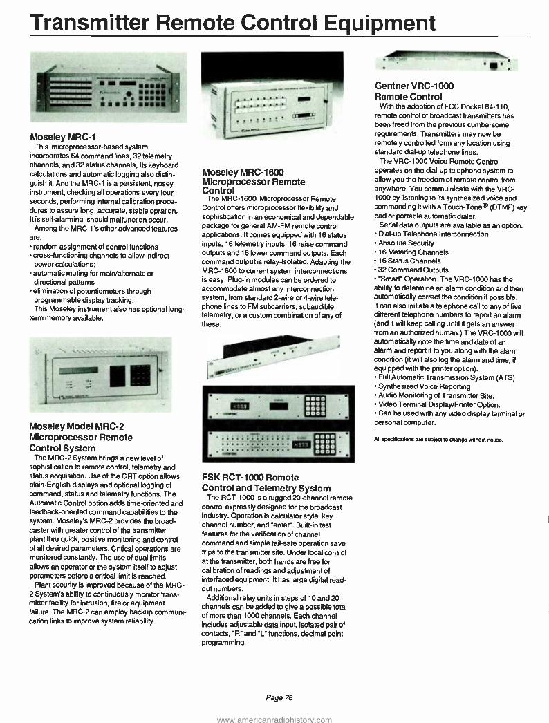
Transmitter Remote Control Equipment
Moseley MRC -1 This microprocessor -based system
incorporates 64 command lines, 32 telemetry channels, and 32 status channels, Its keyboard calculations and automatic logging also distin- guish it. And the MRC -1 is a persistent, nosey instrument, checking all operations every four seconds, performing internal calibration proce- dures to assure long, accurate, stable opration. It is self -alarming, should malfunction occur. Among the MRC -1's other advanced features
are: random assignment of control functions cross -functioning channels to allow indirect power calculations; automatic muting for main /alternate or directional patterns elimination of potentiometers through programmable display tracking. This Moseley instrument also has optional long-
term memory available.
Moseley Model MRC -2 Microprocessor Remote Control System
The MRC -2 System brings a new level of sophistication to remote control, telemetry and status acquisition. Use of die CRT option allows plain -English displays and optional logging of command, status and telemetry functions. The Automatic Control option adds time-oriented and feedback -oriented command capabilities to the system. Moseley's MRC -2 provides the broad- caster with greater control of the transmitter plant thru quick, positive monitoring and control of all desired parameters. Critical operations are monitored constantly. The use of dual limits allows an operator or the system itself to adjust parameters before a critical limit is reached.
Plant security is improved because of the MRC - 2 System's ability to continuously monitor trans- mitter facility for intrusion, fire or equipment failure. The MRC -2 can employ backup communi- cation links to improve system reliability
Moseley MRC -1600 Microprocessor Remote Control
The MRC -1600 Microprocessor Remote Control offers microprocessor flexibility and sophistication in an economical and dependable package for general AM -FM remote control applications. It comes equipped with 16 status inputs, 16 telemetry inputs, 16 raise command outputs and 16 lower command outputs. Each command output is relay -isolated. Adapting the MRC -1600 to current system interconnections is easy. Plug -in modules can be ordered to accommodate almost any interconnection system, from standard 2 -wire or 4 -wire tele- phone lines to FM subcarriers, subaudible telemetry, or a custom combination of any of these.
FSK RCT -1000 Remote Control and Telemetry System
The RCT -1000 is a rugged 20channel remote control expressly designed for the broadcast industry. Operation is calculator style, key channel number, and "enter. Built -in test features for the verification of channel command and simple fail -safe operation save trips to the transmitter site. Under local control at the transmitter, both hands are free for calibration of readings and adjustment of interfaced equipment. It has large digital read- out numbers.
Additional relay units in steps of 10 and 20 channels can be added to give a possible total of more than 1000 channels. Each channel includes adjustable data input, isolated pair of contacts, "R" and "L" functions, decimal point programming.
Page 76
Gentner VRC -1000 Remote Control
With the adoption of FCC Docket 84 -110, remote control of broadcast transmitters has been freed from the previous cumbersome requirements. Transmitters may now be remotely controlled form any location using standard dial -up telephone lines.
The VRC -1000 Voice Remote Control operates on the dial -up telephone system to allow you the freedom of remote control from anywhere. You commuinicate with the VRC - 1000 by listening to its synthesized voice and commanding it with a Touch -Tone® (DTMF) key pad or portable automatic dialer.
Serial data outputs are available as an option. Dial -up Telephone Interconnection Absolute Security 16 Metering Channels 16 Status Channels 32 Command Outputs "Smart" Operation. The VRC -1000 has the
ability to determine an alarm condition and then automatically correct the condition if possible. It can also initiate a telephone call to any of five different telephone numbers to report an alarm (and it will keep calling until it gets an answer from an authorized human.) The VRC -1000 will automatically note the time and date of an alarm and report it to you along with the alarm condition (it will also log the alarm and time, if
equipped with the printer option). Full Automatic Transmission System (ATS) Synthesized Voice Reporting Audio Monitoring of Transmitter Site. Video Terminal Display /Printer Option. Can be used with any video display terminal or
personal computer.
All specifications are subject to change without notice.
www.americanradiohistory.com

Transmitter Remote Control Equipment
Potomac Instruments RC16+ Automatic Remote Control System Standard Features
16 Telemetry Channels 16 Status Channels 32 Control Functions Single Point Calibration Microprocessor Continuous Scan Automatic Tolerance Alarms Power Fail Memory Automatic Pattern /Power Switching Automatic Transmitter Power Control Automatic Transmitter Re -Start Direct Antenna Monitor Interface Easily Installed Simple to Operate Potomac Instruments Quality and Reliability
Optional Features Expandable (in groups of 16) to:
64 Telemetry Channels 64 Status Indicators 128 Control Functions
Plug -In Auto Logger Selectable Logging Intervals Selectable Logging Sequence Out -of -Limit Flags
CRT Display Displays all Telemetry Data Continuous Update Out -of -Limit Flags
The RC 16+ is designed to simplify operator workload at remote controlled AM and FM
Broadcast Stations. In addition to the manual telemetry,
control, and status functions available in
conventional remote control systems, the RC
16+ provides continuous monitoring of all
telemetry data and automatic control of certain operating parameters.
Any out -of -limit condition triggers an open collector output at the rear panel which may be
used to drive a relay, a light, a sounder or a
combination of these to alert station operators. If an out -of -limit condition occurs for a para- meter which can be remotecontrolled, the operator simply selects the MANUAL mode of operation, steps to the appropriate channel, and activates the RAISE or LOWER push- button to adjust that parameter to within specified tolerances.
The RC 16+ is also capable of automatically selecting transmitter power level and/or antenna pattern.
TFT 8610 Series Digital Remote Control System
The TFT 8610 System makes it possible for any size AM, FM or TV station to have direct, digital control of remote transmitters. The system is modular to accomodate future additions /revisions.
With the 8610 series, interconnection can be
via telephone lines or radio links. Radio links include STL and SCA or TSL. Pulse Code Modulation (PCM) is used for data transmission, and the system has built -in
digital data modems. Data accuracy and greatly reduced operator
errors are ensured by TFT -proprietary digital data filtering and closed loop automatic verification systems. In digital data filtering, each control command is sent twice. The two
are then compared at the remote point, bit by bit. Only if they match exactly are the commands carried out.
Modular, field expandable design Fully digital, pulse code modulated FSK modems Linked by telephone wire line or STL and SCA One man calibration 10 to 80 channels of RAISE/ LOWER and TELEMETRY functions Up to 30 channels of direct ON /OFF control Up to 64 channels of STATUS and ALARM monitoring Limit alarms and optional automatic logging Quick -disconnect barrier -strip boards for easy service of remote units Provision for Automatic Transmission System (A.T.S.) operation built -in
Complete line of accessories for transmitter and monitoring interface
SYSTEM COMPONENTS The Models 8610 and 8611 are the basic
building blocks of the versatile 8610 system. Although it is a fully stand -alone, 10 channel digital system with RAISE/LOWER functions and 10- channels of telemetry, the 8610 Series System can be field expanded to meet the needs of even the largest station by merely adding additional models 8631 Channel Expander and Models 8632/8633 Status/Alarm to increase the number of telemetry and status channels.
Page 77
SPECIFICATIONS Power: Model 8610: 115/220 volts ac ±10 %, 50 to
400 Hz, 15 watts max. Model 8611: 115/220 volts ac, ±10 %, 50 to
400 Hz, 25 watts max. Model 8631: From Model 8611 Model 8632: 115/220 volts ac ±10 %, 50 to
400 Hz, 15 watts max. Model 8633: 115/220 volts ac ±10 %, 50 to
400 Hz, 15 watts max. Operating temperature, all models: 0° C to
50° C (32° F to 122° F)
Humidity, all models: up to 95% non -
condensing Size: All 8610 System units are designed for 19" (48.26 cm) rack mounting Model 8610: 5.25" (13.34 cm) H x 13"
(33.02 cm) D; 12 Lbs (5.40 kg)
Model 8611: 5.25" (13.34 cm) H x 13"
(33.02 cm) D; 16 lb (7.2 kg) Model 8631: 5.25" (13.34 cm) H x 13"
(33.02 cm) D; 6 Lbs (2.7 kg) Model 8632, 8633: 3.5" (8.89 cm) H x 13"
(33.02 cm) D; 10 Lbs (4.5 kg)
AMD TC -8 Remote Control System 8 metering channels 8 status inputs 8 raise, 8 lower outputs Delayed failsafe output One -person calibration Non -volatile memory Large dot -matrix display Optional computer interface Radio or wire link Advanced Micro -Dynamics' TC -8 System is
designed to provide highly reliable transmitter remote control at a modest cost. All inputs are filtered to provide RF immunity. Non -volatile memory stores all setup and calibration data for ten years without power, allowing convenient maintenance and providing orderly recovery from power outages.
SPECIFICATIONS Power: 117 volts ac nom. 50/60 Hz 30 watts; may be strapped for 230 volts; Toroidal transformer allows operation from UPS or inverter Size: 1.75" (4.45 cm) H x 19" (48.26 cm) W x
11" (27.94 cm) D (EIA standard rack mount)
All specifications are subject to change without notice.
www.americanradiohistory.com

STL Equipment
Mosely PCL -505 and 505Á/C Systems
The PCL -505 system links studio to trans - mitter -or studio to studio or whatever "closed - circuit" network you need. With its transmitter and receiver you can send and receive signals ranging from 148 mhz to 960 mhz, and do so with better than 70 db noise below carrier (AM).
The PCL -505Á/C matches the performance of the standard 505 and goes a step beyond- in- corporating specialized electronics to cope with RF problems in the 890 -960 mhz band. It does so, in part, through its 70 mHz surface acoustic wave I F filter. It's an essential instrument in
today's crowded RF spectrum.
Models PCL -606 and PCL -606/C
PCL -606 and PCL -606/C Studio -Transmitter Links provide broadcasters and industrial users alike with the highest quality program intercon- nect currently available in equipment of this type. By the use of the latest technology avail- able in today's market, significantly improved specifications and performance are achieved, even in overly congested areas or high density RF environments. Designed for monaural audio service, the PCL -606 can be used in a dual configuration for stereo service. The PCL - 606/C, composite stereo version, conveys composite stereo waveform with virtually no degradation.
Mosely TRL -1 Wireless transmission and reception with the
TRL -1 is quick, quiet, and efficient. Completely solid -state; "linkable" with aural STL's micro- processor, digital or analog control systems; designed for consistent continuous, unattended duty-the TRL -1 operates on the 450 mHz band (other frequencies are available on request).
The TRL -1 has two important options: A modulated Continuous Wave (MCW) identi- fies preprogrammed with alpha/numeric ID.
A battery back -up which is automatically switched on should ac fail. With it, twenty minutes of power can be provided for stand -by operations.
Marti STL -10 The Marti Studio -Transmitter Link/Intercity
Relay is a line -of -sight FM communication system providing a high quality broadcast audio channel with two optional sub -channels. A dual link for stereo provides two identical broadcast quality channels with better than 60 db stereo cross talk and four optional sub -channels. This system offers greater rejection of interference, superior noise performance, lower channel cross talk, greater redundancy, and lower cost than composite STL's currently available.
Applications of the STL -10 include: STL for FM stereo broadcast (Dual system) STL for AM stereo broadcast (Dual system) STL for FM mono or AM broadcast. Intercity relay for linking two or more broadcast facilities. Multi -relay system for radio network distribution. Communications link between satellite earth station and broadcast facilities.
j..._.: [rb !. ___2__ ._.
Marti TSL -2, TSL -15 and TSL -25
The Marti TSL Telemetry Links provide reliable telemetry circuits for AM, FM and television stations. Expensive and unreliable Telco lines can now be replaced with cost effective Marti TSL Systems. These links are simple to install, easy to operate and maintain. Marti has assem- bled complete equipment packages consisting of Transmitter, Receiver, Yagi Antennas, Cable, Identifier and optional items. The 2.5 watt transmitter is available for solar power or other limited power source applications. The 15 watt transmitter is recommended for use on medium to long paths having high signal attenuation. Features Choice of Transmitter Power -2.5 or 15 or 25 watts Continuous Duty Transmitters are FCC type accepted. Super -Selective Receiver with 90 db spurious rejection. Test Meter built into both transmitter and receiver. Receiver has adjustable squelch and carrier operated relay. Built -in modulation control. Internal ac Supply in transmitter and receiver with provision for external dc operation. Optional Automatic Station Identifier. Analog or Digital Telemetry or Voice Modula- tion in 50 Hz -3000 Hz band. Mic and Line Level Inputs with mixing controls.
Page 78
TFT 8300 Series Wideband- Composite STL System TFT 8300 broadcast quality aural Studio Trans- mitter Link and inter-city relays open a new generation of superior STL technology keyed to the increasing demand for system performance and versatility. They are the result of years of experience in STL and FM Transmitter monitor- ing technology. To meet today's demand for improved signal -to -noise ratio, better stereo separation, reliable operation in dense RF signal environments, AM stereo applications and auto -matic "hot- standby" switch over, such state -of- the -art features are all incorporated into the revolutionary design of the new TFT 8300 Series.
Mark Products P -948G Parabolic antenna Antenna is of multigrid construction and is
extremely strong and rigid. It will withstand wind thrusts up to 161 km/h (100 mile per hour). Operating in the 890- to 960 -MHz range, the P -948G has a front -to -back ratio of 28 dB and gain of 18.9 dB. Size: 4" (1.2 m) Dia.; Wgt: 25 lb (11.3 kg) P -948G NPN: 1.2 m (4') Parabolic Antenna
Mark Products MG -944GN Parabolic Antenna Cylindrical parabolic antenna operates in the 940 to 960 MHz range. Gain is 13.5 dB, front -to- back ratio is 20 dB. Welded grid construction. Size: 13 -1/2" (29.2 cm) H, 44" (111.8 cm)
W, 17" (43.2 cm) D; Wgt: 7 Ib (3 2 kg) MG -944GN NPN: Cylindrical Parabolic Antenna
SCALA PR -450U Antenna This strong, swiftly mounted instrument (with
an exclusive balun feed) guarantees equal distri- bution of current in the driver element. The ano- dized, dichromate PR -450U is incredibly resis- tive to corrosive elements. Its impedance is 50 to 75 ohms. Connection is via a type NRF female coupler. Gain is 15 dB; front to back ratio is 20 dB. Size: 67" (170 cm) H, 36" (91 cm) W, 19"
(48 cm) D; Wgt: 25 lb (11.25 kg)
All specifications ace subject to change without notice.
www.americanradiohistory.com

Monitors
Belar AMM -2/ -3 AM Modulation Monitor
Both the AMM -2 and AMM -3 modulation monitors incorporate true ratio -type peak indicators and a unique modulation cancellation scheme to recover unmodulated carrier with which to reference the modulation peaks. The AMM -2, with one modulation meter, and the AMM -3, with two modulation meters, respond accurately to the shortest duration program peaks.
The AMM -2 has a single adjustable peak modulation indicator; 40 to 130 percent in less than 1- percent increments. Model AMM -3 has two adjustable peak modulation indicators: positive 1 to 199 percent; negative 1 to 99 percent. Both indicators are independent of carrier level. Both models are equipped with separate negative and positive indicator lamps (AMM -2) or LED; (AMM -3). Model AMM -3 has outputs for listening as well as test functions. Size, AMM -2: 5 -1/4" (13.3 cm) H x 19"
(48.26 cm) W x 6" (15.24 cm) D
Weight: 8 lb (3.62 kg) Size, AMM -3: 5 -1/4" (13.3 cm) H x 19"
(48.26 cm) W x 8-1/2 " (21.59 cm) D
Weight: 8 Ib (3.62 kg)
Belar Model SCM -1 SCA Frequency & Modulation Monitor
The Belar FM monitors were designed as a
totally integrated, solid state system to enable the broadcaster to fulfill his monitoring equipment requirements as the need arises. The Belar SCM -1 SCA Frequency and Modulation Monitor, when added to the FMM -1
Frequency and Modulation Monitor, provides complete monitoring and test functions for SCA storecasting and remote telemetering applications. Up to four crystal switch positions allow four channels to be operated and tested. Size: 5 -1/4" (13.34 cm) H x 10 -1/2" (26.67 cm)D
x 19" (48.26 cm) W Shipping Weight: 12 lbs. (5.4 kg)
Belar Automatic AM Frequency Monitor AMM -4
The Belar AMM -4 is a digital AM frequency monitor designed especially for automatic broadcast transmitter monitoring. The counter will accurately monitor any frequency from 10
kHz to 50 MHz. A large 3 -1/2 digit LED readout provides a display range of ±1999 Hz deviation from the assigned channel. A front panel LED indicator warns of low RF level or loss of carrier; an optional relay contact can be provided. The monitor also provides two off -frequency alarms which are inhibited so that three successive errors are required to signal an alarm. This prevents false off- frequency conditions.
Relay contact outputs are available as op- tions. A switchable 1 MHz input/output connec- tor is provided for frequency comparison. Features Inhibited off- frequency alarms 10 Hz off -frequency alarm 20 Hz off -frequency alarm RF level alarm Invalid count alarm Count inhibit input External timebase input
1 MHz output 3 -1/2 digit LED display Low profile design Designed for ATS operation
SPECIFICATIONS Frequency Range: 10 kHz to 50 MHz Display: Large 3 -1/2 digit LED Display Range: ±1999 Hz
Sensitivity: 100 mv, Unmodulated 2 V rms, 99% modulation
Gate Time: 2 seconds Resolution: 0.5 Hz
Time Base (Internal): 3 MHz Stability: ±1 x 10⁻⁶ per year Time Base (External):
1 MHz, TTL compatible level 10 Hz alarm: Front panel LED, warns of
potential frequency fault, inhibited for three successive errors
20 Hz alarm: Front panel LED, inhibited for three successive errors
RF alarm: Front panel LED, warns of low RF level or carrier fail condition
Invalid Count Alarm: Prevents false counts due to low RF level or problem in counter
Count Inhibit Input: External contact required capable of sinking 2mA
Dimensions: 1.75" (4.45 cm) H x 19" (48.26 cm) W (EIA rack mount)
Power Requirements: 100/220 vac, 50/60 Hz
OPTIONS Relay card for frequency alarms, RF level alarm
Page 79
Belar Model FMM -2 FM Modulation Monitor
The Belar Model FMM -2 FM Modulation Moni-
tor is a precision wideband, all solid state FM
monitor, designed to measure the total modu- lation characteristics of monaural as well as multiplexed FM transmitters. The model FMM -2
is also used as a low distortion and low noise FM
demodulator to drive the companion stereo and SCA monitors, as well as providing audio outputs for aural monitoring and proof of
performance measurements. The Model FMM -2 has set new standards in
totally accurate measurement techniques. Utilizing such advanced design features as an
ultra -linear digital discriminator, an almost dis- tortionless and absolutely flat baseband signal is produced to ensure precise stereo and SCA decoding.
In addition to the normal FCC defined semi - peak metering, the FMM -2 incorporates a
sample -hold peak modulation meter circuit, indpendent of modulation polarity, to allow the
meter to respond accurately to program peaks. Size: 5 -1/4" (13.34 cm) H x 10 -1/2" (26.67 cm)D
x 19" (48.26 cm) W; (EIA Rack Mount) Power Consumption: 10 watts, 117 vac
std. (234 vac opt) 50/60 Hz Shipping Weight: 12 lbs (5.4 kg)
411111111110
Belar Model FMS -2 Stereo Modulation Monitor
The Belar Model FMS -2 Stereo Modulation Monitor is an all solid state precision stereo monitor designed to operate in conjunction with the Belar Model FMM -2 baseband modulation monitor. The FMS -2 is also used for test functions in conjunction with the model FMM -2
to ensure proper performance of FM stereo transmitters. The test and measurement capability of the FMS -2 is further enhanced by
the integration of two independent auto -ranging voltmeters allowing automatic measurement of
channel separation and cross -talk, along with sub -carrier suppression and noise. For example, depressing the left and right channel buttons automatically registers the wanted and unwanted channel for instant separation measurements. A front panel hold button can be
used to lock the autorange to the displayed range. Size: 5 -1/4" (13.34 cm) H x 10 -1/2" (26.67 cm)D
x 19" (48.26 cm) W; (EIA Rack Mount) Power Consumption: 15 watts, 117 VAC
std. (234 vac opt) 50/60 Hz Shipping Weight: 17 lbs (7.65 kg)
All specr ications subject to change without note.
www.americanradiohistory.com

Transmitter Monitor & Test Equipment
TFT Model 844 FM Stereo Modulation Monitor
Based on TFT's 14 years of engineering experience -with over 5,000 modulation monitors operating world-wide--these third generation instruments bring you innovations that solve today's modulation problems, using today's advanced technology. You get everything you need for complete proof -of- performance measurements (for distortion, an external analyzer is needed) right on the front panels, plus accuracy, versatility and conveni- ence no other monitors can match.
The Model 844 combines a tuneable RF preselector, a baseband monitor and a stereo monitor in one compact instrument. The Model 845 SCA monitor is a multi -frequency instrument designed for use with the Model 844. With an optional receiver module, the 845 can be used as a stand -alone unit for both off-air and direct transmitter monitoring.
Both the Model 844 and the Model 845 can be used for remote, off-air monitoring or for direct transmitter measurements. Both are also adapt- able to Automatic Transmission System (ATS) use. Additionally, the Model 844 features 50 kHz, frequency synthesized channel tuning, to accommodate all U.S. and international standards. Size: Mounts in 19" rack; 7" (17.78 cm) H
x 19 "(48.26cm) W x 15 "(38.10 cm) D
Power: 115/230 ± 10% vac, 50 to 400 Hz, 40 watts max.
Weight: 22.5 lb (10.2 kg) approx.
Potomac Instruments Type 19 Antenna Phase Monitors Accurate Field proven reliability Push button operation Remote monitoring Upt to 12 towers, DA -3
AM -19 (204) The AM -19 (204) is the current model of the
industry's most widely used solid state antenna monitor. It provides direct meter readout of phase angle and loop current ratio. Tower selection is accomplished with push buttons on the front panel or by external contact closure in
remote operation. Directional antenna arrays of from 2 to 12 towers with DA -1, DA -2 or DA -3 patterns may be monitored with this instrument.
Compatible with virtually every type of wire or wireless remote control system, the AM -19 (204) requires no external line interface equip- ment. Analog or digital remote metering panels are available for studio readout and may be added at any future date. Size: Mounts in 19" rack;
7" H, 12 -3/4" D
Power: 105 to 130 volts ac, 50/60 Hz Weight: 20 lb (Approx.)
Page 80
r _.tz ._
AM -19D (210) Features Same as AM -19 (204) features plus Numeric Readout Phase resolution 0.1° Ratio resolution 0.1
Modular construction Ratios to 199.9% The AM -19D (210) is identical to the AM -19
(204) except for the digital panel meters and associated circuitry. Four digit LED numeric displays provide resolution of 1/10 of one degree (phase angle) and 1/10 of one percent (current ratio). The digital readout feature of this instrument virtually eliminates operator error related to meter interpretation. Remote switching and readout are accomplished as in the AM -19 (204).
Inherently stable circuit design, modular con- struction, simplicity of operation and moderate cost make the AM -19D (210) the truly optimum monitor for directional stations utilizing lessor grade operators. Size: Mounts in 19" rack;
7" H, 12 -3/4" D
Power: 105 to 124 volts ac, 50/60 Hz Weight: 20 lbs ( approx.)
-11111111111116.
1 8 0.0
LI- Ilt/L-
PMA -19 Current deviation mode Ultimate precision Up to 12 towers, DA -3 The PMA -19 Precision Monitor Adaptor is
used in conjunction with either the AM -19 (204) or the AM -19D (210) monotors. This unit is
required, for the most part, in very critical arrays. The current deviation mode provides a
third measured parameter which displays directly the deviation of the current ratio from the licensed ratio. Size: Mounts in 19" rack;
14" H, 15 -3/4" D
Power: 105 to 130 volts ac, 60 Hz Weight: 40 lbs (approx)
AH specrlicalions are subject to change without notice.
www.americanradiohistory.com

EBS Equipment
TFT Model 760 EBS System The Model 760 EBS System is designed for
broadcasters to meet Parts 73.940, 73.941 and 73.942 of the FCC Rules and Regulations for decoding and encoding the two -tone EBS alert signal. The modular construction of the system provides for maximum versatility and consists of a cabinet assembly, AM or FM receiver, two - tone decoder and two -tone generator. Two or three of these modules can be combined into a
cost -effective operational EBS System. FCC type accepted and certified.
Complete modular design Frequency synthesized tunable AM receiver Dual channel FM receiver available
Model 760 Cabinet Assembly The Model 760 Cabinet Assembly is designed
to accept up to three of the EBS modules described below. Standalone units may be
constructed by ordering the Model 760 cabinet and any particular module. A fully loaded cabinet would consist of the Two -Tone Generator, either AM or FM receiver in the center, and the Two -Tone Decoder on the right. Blank panels are used as fillers where modules are not installed.
Model 760 -02 Dual Channel FM Receiver
The FM Receiver, Model 760 -02 is a a high performance dual -channel, fixed frequency FM broadcast receiver. Channel selection is
accomplished by a pushbutton switch. Both channels are fixed tuned and the crystals are factory installed. A one-channel version is also available. The CARRIER light will come on only when the desired station is received. A rear panel terminal is provided for activating external carrier-off alarm circuitry. Specify number of channels and frequency with order.
Model 760 -01 Tunable, Frequency Synthesized Receiver
The AM receiver, Model 760 -01, is a
continuously tunable AM broadcast receiver using a frequency synthesized local oscillator which is phase locked to a 5 -MHz crystal oscillator. The local oscillator is tuned by means of a 3 -digit front panel thumbwheel switch in 10-
kHz steps. The stability of the receiver is that of the crystal oscillator regardless of which AM channel is being received.
Positive tuning to any desired station is
accomplished by dialing the frequency of the
selected station and peaking the RF amplifier tuning. The CARRIER light will come on only when the desired station is received. A rear panel terminal is provided for activating external carrier-off alarm circuitry.
In addition to broadcast station use the AM Receiver provides a low cost monitor for all
emergency service agencies, such as police, fire, Civil Defense, hospitals, etc. These services can listen to key EBS participating stations in the local area during any emergency.
Model 760 -03 Two -Tone EBS Decoder
The TFT Two -Tone Decoder, Model 760 -03, decodes the 853 -Hz and 960 -Hz EBS signaling tones from the demodulated output of a
receiver. It may be used in conjunction with TFT's Model 760 -01 AM Receiver, Model 760 -02 FM Receiver, or any audio source which has the EBS Two -Tone signal at 100 mV rms or greater. Stable piezoelectric tuning fork filters are used to achieve ±5 -Hz bandwidth from the center frequency of each tone. The timing circuit for the 10- second delay is a signal averaging integrater which eliminates false turn -on by noise. An amplifier and loudspeaker are built -in
for audio monitoring. Volume control is internally preset.
Model 760 -05 Dual -Purpose Decoder
The Model 760 -05 Dual- Purpose Decoder can be used with either AM or FM receivers to respond to the present carrier break and 1000 - Hz tone signaling scheme or, by removing a
component, decode the new EBS 853- and 960 - Hz dual -signaling tones. The circuit design and electrical characteristics are similar to the Model 760 -03 module.
Model 760 -04 Two -Tone Generator
The Two -Tone EBS Generator, Model 760 -04, generates the 853 -Hz tones simultaneously with an accuracy of ±0.25 Hz. The frequency and stability of the tones are accomplished by synthesizing the tones from a single crystal oscillator.
Model 760 -04 should be installed in the program audio line before the audio limiter. A single channel of audio can be routed through the generator. When the generator is activated, program audio is automatically interrupted, the EBS tones inserted, and The Emergency Program Audio is connected to the output. Program audio is restored by the RESET switch.
The generator is activated by two front panel COMMAND switches which need to be simultaneously operated to prevent accidental activation. COMMAND and RESET functions can be remotely controlled through rear panel wiring. The amplitude of each tone can be checked and adjusted individually. Model 760 Emergency Broadcast System; Time and Frequency Technology, Inc. System Size: 3.5" (8.9 cm) H
19" (48.3 cm) W 12" (30.5 cm) D
System weight: 10 lb (4.5 kg)
All specdications are subiect to change without notice.
Page 81
www.americanradiohistory.com

Audio Processing Equipment
CRL Audio AM -4 Audio Processing System for AM
The CRL AM -4 is the result of years of
research by engineers who have devoted their careers to broadcasting. This work has resulted in the best audio processing equipment on the market today. We welcome comparison testing with other products Input Unit of the AM -4: APP -400 Audio Preparation Processor
The unique design of the APP 400 allows it to
automatically correct for errors in audio source program levels, tonal balance, and other quali- ties most AGC's simply cannot handle. Totally unlike any other AGC, the APP -400 actually enhances transient musical qualities and punch while maintaining perfect level control. FEATURES Asymmetry removal User -controlled loudness De- essing Easy, programmable accessing of low input levels Selectable AGC gating action Maintenance ce -free, high tech internal circuitry Multiband Gain Control User -controlled output equalizing Dynamic equalization Internal pink noise generator for easy system set -up Active balanced input and output circuitry
Center Unit of the AM -4: SEP -400A Spectral Energy Processor FEATURES
Four -channel multiband control Four -channel equalizer configuration Selectable level four -band gating action Active balanced input and output circuitry Selectable peak transient limiters Novel peak compression Maintenance -free internal circuitry
Output Unit of the AM -4: PMC -300A Peak Modulation Controller
The PMC -300A has three important functions The unit provides the necessary final audio peak control for maximum transmitted coverage and loudness. Additional CRL pioneered techniques shape the audio spectrum to help correct any transmitter and antenna system deficiencies that may exist in
the radio station. FEATURES
Unique multiband control with pre -emphasis Transmitter distortion correction Selectable high pass filter for older transmitters High positive peak density to well over 140% Distortion anticipation Bandwidth -controlled clipping filter
Auto clip feedback of clipping filter to
input G'R stages Over -modulation prevention Active balanced input and output circuitry
Size, complete system: 19" (48.26 cm) Rack Mounting, x 5 -1/4" (13.34 cm) H x
12" (30.48 cm) D. Each unit is 1 -3/4" (4.45 cm) H x 12" (30.48 cm) D
Power: 110 -125 volts ac, 50/60 Hz, 40 watts
CRL Audio AM -4 Stereo Matrix Processing System for AM The SMP -900, AM Stereo Matrix Processor
was developed to improve AM Stereo /monaural compatibility. It must be understood that they are not really compatible. AM Stereo has a
unique problem. With conventional left and right limiting a LOSS of 6 db in loudness can occur when receiving left OR right ONLY stereo information in MONO. Processing can eliminate this problem, but will cause up to 6 db INCREASE in loudness during single channel STEREO reception. The CRL SMP -900 minimizes this problem by providing a continu- ously variable control that will allow adjustment of the signal between the two extremes for best overall sound. This unit will actually improve actually improve your MONO signal in both fidelity and coverage.
Input Unit of the AM-4S SPP -800 Stereo Preparation Processor
The unique design of the SPP -800 allows it to
automatically correct for errors in audio source program levels, tonal balance, and other quali- ties most AGC's simply cannot handle. Totally unlike any other AGC, the SPP -800 actually enhances transient musical qualities and punch while maintaining perfect level control. FEATURES Asymmetry Removal (optional) Multiband Gain Control User Controlled Loudness User Controlled Output Equalizing De -essing Dynamic Equalization Programmable AGC'ing of low input levels Selectable AGC Gating Action Maintenance Free, High Technology Internal Circuitry Internal Pink Noise Generation for Easy System Set Up Active Balanced Input and Output Circuitry Special Stereo Strapping Technique
Center Units of the AM -4S: SEP -400A Spectral Energy Processor
The SEP -400A is designed to give you the capability of carefully shaping and altering the program tonal quality in four precisely chosen
Page 82
bands per channel. It also provides an increase in audio loudness while maintaining a musical quality. FEATURES
Four Channel Multiband Control Selectable Peak Transient Limiters Four Channel Equalizer Configuration Selectable Level Four Band Gating Action Maintenance Free Internal Circuitry Active Balanced Input and Output Circuitry Left and Right Channels are Closely Balanced
Output Unit of the AM -4S: SMP -900 Stereo Modulation Processor
The SMP -900 is the final unit in the AM-4S system. It is a combination processor/limiter utilizing patented CRL circuits and filters for maximum fidelity and modulation levels. FEATURES
Mono Support Gain Reduction Variable High Frequency Pre -Emphasis Control Stereo Enhance Control Single Channel Negative Limiting L +R and L -R Output Controls Separate Mono Out, Adjustable Tilt Correction Control Setup Testing Switch Low Pass Filter Switch (11 kHz and 9 kHz)
Size, complete system: 19" (48 26 cm) rack mounting x 5-1/4" (13 34 cm) H x 12" (30.48 cm) D. Each unit is 1 -3/4' (4.45 cm) H
x 12" (30.48 cm) D
Power: 110 -125 volts ac, 50/60 Hz, 40 watts
CRL Audio FM -2 Stereo Processing System for FM Input Unit of FM -2: SPP -800 Stereo Preparation Processor
The unique design of the SPP -800 allows it to automatically correct for errors in audio source program levels, tonal balance, and other quali- ties most AGC's simply cannot handle. Totally unlike any other AGC, the SPP -800 actually enhances transient musical qualities and punch while maintaining perfect level control. FEATURES Asymmetry Removal (optional) Multiband Gain Control User Controlled Loudness User Controlled Output Equalizing De- essing Dynamic Equalization Programmable AGC'ing of Low Input Levels Selectable AGC Gating Action Maintainance Free, High Technology Internal Circuitry Internal Pink Noise Generation For Easy System Set Up Active Balanced Input and Output Circuitry Special Stereo Strapping Technique
Ali specdicabons are subject to change without nane.
www.americanradiohistory.com
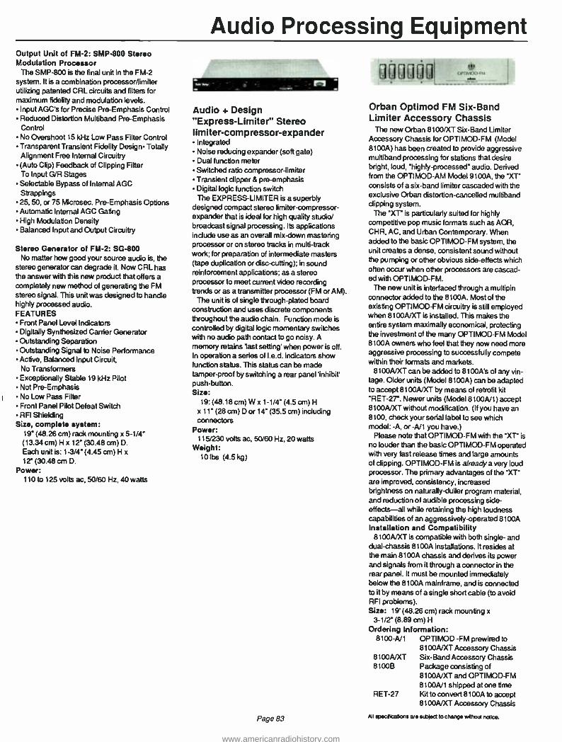
Audio Processing Equipment Output Unit of FM -2: SMP -800 Stereo Modulation Processor
The SMP -800 is the final unit in the FM -2
system. It is a combination processor/limiter utilizing patented CRL circuits and filters for maximum fidelity and modulation levels. Input AGC's for Precise Pre -Emphasis Control Reduced Distortion Multiband Pre -Emphasis Control No Overshoot 15 kHz Low Pass Filter Control Transparent Transient Fidelity Design- Totally Alignment Free Internal Circuitry (Auto Clip) Feedback of Clipping Filter To Input G/R Stages Selectable Bypass of Internal AGC Strappings 25, 50, or 75 Microsec. Pre -Emphasis Options Automatic Internal AGC Gating High Modulation Density Balanced Input and Output Circuitry
Stereo Generator of FM -2: SG -800 No matter how good your source audio is, the
stereo generator can degrade it. Now CRL has the answer with this new product that offers a completely new method of generating the FM stereo signal. This unit was designed to handle highly processed audio. FEATURES
Front Panel Level Indicators Digitally Synthesized Carrier Generator Outstanding Separation Outstanding Signal to Noise Performance Active, Balanced Input Circuit, No Transformers Exceptionally Stable 19 kHz Pilot Not Pre -Emphasis No Low Pass Filter Front Panel Pilot Defeat Switch RFI Shielding
Size, complete system: 19" (48.26 cm) rack mounting x 5 -1/4- (13.34 cm) H x 12" (30.48 cm) D.
Each unit is: 1 -3/4" (4.45 cm) H x
12" (30.48 cm D. Power:
110 to 125 volts ac, 50/60 Hz, 40 watts
Audio + Design "Express-Limiter" Stereo limiter-compressor-expander
Integrated Noise reducing expander (soft gate) Dual function meter Switched ratio compressor -limiter Transient dipper & pre- emphasis Digital logic function switch The EXPRESS -LIMITER is a superbly
designed compact stereo limiter- compressor- expander that is ideal for high quality studio/ broadcast signal processing. Its applications include use as an overall mix -down mastering processor or on stereo tracks in multi -track work; for preparation of intermediate masters (tape duplication or disc-cutting); in sound reinforcement applications; as a stereo processor to meet current video recording trends or as a transmitter processor (FM or AM).
The unit is of single through -plated board construction and uses discrete components throughout the audio chain. Function mode is
controlled by digital logic momentary switches with no audio path contact to go noisy. A memory retains 'last setting' when power is off. In operation a series of I.e.d. indicators show function status. This status can be made tamper -proof by switching a rear panel 'inhibit' push- button. Size:
19: (48.18 cm) W x 1-1/4" (4.5 cm) H
x 11" (28 cm) D or 14" (35.5 cm) including connectors
Power: 115/230 volts ac, 50/60 Hz, 20 watts
Weight: 10 lbs (4.5 kg)
Page 83
Orban Optimod FM Six -Band Limiter Accessory Chassis
The now Orban 8100/XT Six -Band Limiter Accessory Chassis for OPTIMOD -FM (Model 8100A) has been created to provide aggressive multiband processing for stations that desire bright, loud, "highly- processed" audio. Derived from the OPTIMOD -AM Model 9100A, the "XT" consists of a six -band limiter cascaded with the exclusive Orban distortion -cancelled multiband clipping system.
The "XT- is particularly suited for highly competitive pop music formats such as AOR, CHR, AC, and Urban Contemporary. When added to the basic OPTIMOD -FM system, the unit creates a dense, consistent sound without the pumping or other obvious side - effects which often occur when other processors are cascad- ed with OPTI MOD -FM.
The new unit is interfaced through a multipin connector added to the 8100A. Most of the existing OPTIMOD -FM circuitry is still employed when 8100A/XT is installed. This makes the entire system maximally economical, protecting the investment of the many OPTIMOD -FM Model 8100A owners who feel that they now need more aggressive processing to successfully compete within their formats and markets.
8100A/XT can be added to 8100A's of any vin- tage. Older units (Model 8100A) can be adapted to accept 8100A/XT by means of retrofit kit "RET -2T. Newer units (Model 8100A/1) accept 8100A/XT without modification. (If you have an 8100, check your serial label to see which model: -A, or -A/1 you have.)
Please note that OPTIMOD -FM with the "XT" is
no louder than the basic OPTIMOD FM operated with very fast release times and large amounts of clipping. OPTIMOD -FM is alreadya very loud processor. The primary advantages of the "XT" are improved, consistency, increased brightness on naturally -duller program material, and reduction of audible processing side - effects -all while retaining the high loudness capabilities of an aggressively-operated 8100A Installation and Compatibility
8100A/XT is compatible with both single- and dual -chassis 8100A installations. It resides at the main 8100A chassis and derives its power and signals from it through a connector in the rear panel. It must be mounted immediately below the 8100A mainframe, and is connected to it by means of a single short cable (to avoid RFI problems). Size: 19' (48.26 cm) rack mounting x
3 -1/2" (8.89 cm) H
Ordering Information: 8100 -A/1 OPTIMOD -FM prewired to
8100A/XT Accessory Chassis 8100A/XT Six -Band Accessory Chassis 8100B Package consisting of
8100A/XT and OPTIMOD -FM 8100A/1 shipped at one time
RET -27 Kit to convert 8100A to accept 8100A/XT Accessory Chassis
All specrtrations are stbied to change wrhout not ce.
www.americanradiohistory.com

Audio Processing Equipment
modulation sciences inc.
am'
Modulation Sciences CP -803 Composite Processor
The Composite Processor improves the sound of your FM station by eliminating peaks of over - modulation. These peaks occur in two ways: First, the CP -803 eliminates the brief electrical overshoots that exist in all audio limiters and stereo generators-even those described as overshoot-compensated. Preventing such overshoots increases modulation with essen- tially no audible effect on the signal. Second, the Processor controls the high -fre- quency peaks that are present in all program material. Though not acoustically significant, these peaks cause over -modulation. Controlling them makes greater average modulation possible. The audible effect is minimal, far less than that of conventional variable -gain devices.
The CP -803 corrects the distortion that conventional processors sometimes create. But there's a basic difference in their operation: Conventional audio processors work with the left and right audio. But the Composite Pro- cessor deals with the stereo composite signal that comes out of the stereo generator. this baseband signal is made of the left-plus -right main channel, the 19 kHz pilot, and the left - minus -right subcarrier. By working on this signal instead of the left and right audio, many conventional audio problems are avoided. FEATURES
More loudness -up to 6 dB- without audible distortion Less conventional compressing and limiting Cleaner, more -open" sound More distinctive sound
Size: 12' (30.48 cm) W x 1 -3/4' (4.45 cm) H x
5-3/4- (14.61 cm) D. Rack mounting kit available
Power: 90 to 130 volts, 50/60 Hz, 10 watts
Dorrough Electronics Model 610 Audio Processor
The Discriminate Audio Processor Model 610 is a digital controlled tri -band audio processor. A
maximum of three channels has proved to be the most colorless and least modifying of program material. The use of gain reduction independently in the three channels eliminates the typical restrictions heard on single channel devices. It is the intention of this device by virtue of the three bands not to doctor or modify the average or peak of the program content in
any way that would be offensive to the ear. The Discriminate Audio Processor Model 610
operates in the following sequence: Splitter, Three Channels, Program Equalizer, Peak Limiter
Digital Control The unit utilizes a frequency discriminate
digital control signal, operating in real time, to control the action of analog attenuators, which are located within the discriminate path of the input audio signal. LED Metering
LED metering is used for each of the three channels with individual LEDs for indicating quieting mode and clip level. The Output Meter enables precise setting of relative loudness levels desired to peak modulation.
The system is essentially free of all internal adjustment. Equalization
A four position equalizer appears on the front panel and is electrically positioned after the three channels and before the Peak Limiter. These "pleasure" controls are provided for individual tailoring of program material. The instruction manual suggests settings with elect- rical explanations. Peak Limiter
The Peak Limiter is designed with a combina- tion of soft and hard clipping, followed by 15
kHz low pass filter. Peak Limiters are available for AM, FM, and TV applications. Size:
Mounts in 19' (48.26 cm) rack; 5-1 /4' (13.34 cm) H
Power: 110/220 volts ac, 50/60 Hz, 75 watts
Weight: 19 lbs (8.55 kg)
All specifications are subject to change without notice.
Page 84
www.americanradiohistory.com

Stereo Generators
CRL Audio SG -800 Stereo Generator
No matter how good your source audio is, the stereo generator can degrade it. Now CRL has the answer with this new product that offers a completely new method of generating the FM stereo signal. This unit was designed to handle highly processed audio. FEATURES Front Panel Indicators Digitally Synthesized Carrier Generator Outstanding Separation Outstanding Signal To Noise Performance Active Balanced Input Circuit, No Transformer Exceptionally Stable 19 kHz Pilot No Pre -Emphasis No Low Pass Filter Front Panel Pilot Defeat Switch RFI Shielding
Size: 19" (48.26 cm) rack mounting x 1 -3/4" (4.45 cm) H x 12" (30.48 cm) D
Power:110 to 125 volts ac, 50/60 Hz, 40 watts
"°0!IRAI. tifiltR .
Dorrough Model 80 -B Stereo Generator
The 80 -B stereo generator offers state- of -the- art design and performance at a moderate price. Initial set -up is very easy. Performance matches or exceeds other stereo generators available today.
If used with the Dorrough Model 610 "stereo pair" audio processors, the resulting signal is one of the cleanest and loudest on the air today. Size: 19" (48.26 cm) W x 1 -3/4" (4.45 cm) H
x 14" (35.56 cm) D
Orban OPTIMOD -FM This is Orban's second generation com-
pressor/limiter /stereo generator -one that offers unsurpassed loudness and brightness processing side effects.
The OPTIMOD -FM 8100A is a system of components, including:
a unique wideband/multiband compressor which can be exceptionally transparent or as punchy as you like an innovative peak limiter with total over - modulation control- without overshoot, pumping, clipping distortion, or aliasing a stereo generator -new in design -with flawless performance. Because the OPTIMOD -FM has accessible
controls and clear instructions, you're free to tailor your sound for the effect you find best.
OPTIMOD -FM: self- contained, state -of -the- art, and all you need for the best FM signal possible.
Orban OPTIMOD-AM Orban's OPTIMOD -AM 9100A is an advanced
electronic signal processing system that pro- vides the best possible quality, loudness, and high frequency equalization. The result? Transmissions that rival the best FM has to offer. Orban accomplishes this through a six - band frequency -selective limiter with "Smart Clipping," a broadband gain -riding compressor, a program equalizer, a transmitter equalizer, and a totally smooth phase follower and filter.
Orban's pledge is to deliver dramatically improved sound and even to expand signal coverage by concentrating energy in the portion of the audio spectrum that cuts through static and interference. OPTIMOD -AM has yet another advantage in that it is totally adjustable -including Ea, compression and limiting, and clipping up to 12 db. And OPTIMOD -AM does all this with virtually no audible processing side effects.
Page 85
Modulation Sciences Sidekick'N SCA Generator & Audio Processor
Sidekick combines the four elements needed for successful SCA operation into one package: subcarrier generator, modulation monitor, audio processor and transmitter tuning aid. Engineered to work together, these components form an integrated system which provides a level of performance previously unattainable. Crosstalk is dramatically re- duced, signal quality is significantly improved and operation is greatly simplified.
Sidekick is cost effective because there is no need for redundant power supplies, packaging, or input/output interfacing. Subcarrier Generator
Sidekick has the first crystal controlled SCA generator in the industry. Others use simple free -running oscillators which are easy to design and FM modulate, but whose frequency stability is a problem.The stability of Sidekick is
±0.005% from 0 to 50 degrees C. Modulation Monitor
A built -in modulation meter eliminates the need for an additional SCA modulation monitor. The peak holding circuitry lets the meter rise to the maximum deviation and remain there without much wiggling. The meter can also be easily calibrated in the field with only a frequency counter and a DC voltage source. Integrated Audio Processor
Audio processing has traditionally been a weak link in SCA transmission. It is not uncom- mon to find that the audio processors used for SCA are hand -me -down from the main channel. Unfortunately, the use of a 75 microsecond limiter in a 150 microsecond system results in
almost no high -frequency peak control. In
addition, SCA audio filters which roll off at 5
kHz have the same kind of overshoot and ringing as the infamous 15 kHz filters used in
stereo generators. As in main channel operation, poor peak control means low average modulation. In SCA, this means increased susceptibility to crosstalk. Transmitter Tuning Aid
In many transmitters, proper tuning of the driver and PA stages plays a major role in the reduction of crosstalk between the main and SCA channels.
The Sidekick has a built -in noise generator and incidental AM noise meter. No other equipment is needed to noise load the entire baseband and measure the incidental AM from an RF sample. The RF tuning can then be "tweaked" to minimize the incidental AM. This often yields a dramatic reduction in crosstalk. Size: 19" (48.26 cm) W x 3 -1/2" (8.89 cm) H
x 9 -1/4" (23.5 cm) D
Power: 95 -130 volts ac, 50/60 Hz, 12 watts
All specifications are subiect to change without nonce.
www.americanradiohistory.com

Stereo Generators
Moseley Series 8 Subcarrier Systems
Series "8" Subcarrier System forms a revolutionary FM system providing superior performance. The Series "8" System consists of the Model SCG -8 Subcarrier Generator and Model SCD -8 Subcarrier Demodulator. These units may be individually used to meet specific requirements such as SCA service on an FM broadcast transmitter, or telemetry service. This system is ideally suited to aural studio - transmitter link (STL) service. Providing a
means of establishing a secondary program channel, the Series "8" System enables multiplexing SCA program audio, provides for remote pickup link audio, or serves as an interdom on an STL. Command information from a remote control system can also be conveyed by the SCG -8 and SCD -8.
The Model SCG-8 Subcarrler Generator is designed specifically to develop a direct FM subcarrier for multiplexing an FM, TV, or studio -transmitter link transmitter and sound quality are just some of the character- istics of the performance of the SCG -8.
Automatic carrier muting functions with the absence of program audio input. The time delay from the absence of audio until the carrier is
muted can be adjusted from less than 1 second to more than 5 seconds. A front -panel switch enables selection of this automatic -mute fea- ture or a continuous on or off subcarrier condi- tion. A second input applied to a rear -mounted BNC connector accepts a subaudible telemetry signal. Subaudible telemetry information from a
Moseley Associates Remote Control System can be fed directly to the SCG -8.
The Model SCD -8 Subcarrier Demodulator was developed as a companion to the SCG -8 Generator and encompasses the same design philosophy. Input carrier bandpass filtering enables operation from a composite signal source without external filters. This filter is a plug -in assembly enabling easy field changes to other frequencies. The audio output is sufficient to drive most broadcast equipment and is adjustable from the front panel. Carrier bandpass and audio low -pass filters are used in the Series "8" Subcarrier System. Audio performance is tailored to the intended application based upon the carrier frequencies of 26 kHz and 39 kHz, the normal application is either command or telemetry for a
remote system. These applications require a 3
kHz audio bandwidth. Frequencies of 41 kHz and 67 kHz normally are used for SCA service requiring 5 kHz response. As a 67 kHz carrier frequency may also be used for secondary program service on a monaural studio- transmit- ter link (STL), it can optionally be supplied for 10 kHz performance. Likewise, 10 kHz response is provided when operated at a carrier frequency of 185 kHz when using a composite STL for stereo transmission.
Size, Model SCG-8: 19" (48.4 cm) rack mounting x 1 -3/4" (4.5 cm) H x 10" (25.4 cm) D
Weight: 8 lbs (3.6 kg)
Power: 120 -240 volts ac, 50/60 Hz, 10 watts
CRL Audio SCA -2 Subchannel Control System This unit was specifically designed to solve
the problems associated with older SCA equipment. The result is a state-of-the-art unit that brings a new quality to SCA signals. Using the new CRL unit, a station would gain increased coverage without increasing injection levels; improved protection of the main channel signal, increased stability of the whole subcarrier operation, and greatly improved fidelity and intelligibility. Replacing existing equipment with the SCA 300 will result in a dramatic improve- ment in quality.
This integrated SCA system includes audio processing, low distortion crystal controlled oscillator, non- overshooting low pass filters, pre - emphasis and a DC coupled data input port. Input unit of the SCA -2: APP -400 Audio Preparation Processor
The unique design of the APP -400 allows it to automatically correct for errors in audio source program levels, tonal balance, and other qualities most AGC's simply cannot handle. Totally unlike any other AGC, the APP -400 actually enhances transient musical qualities and punch while maintaining perfect level control. FEATURES
Asymmetry Removal (optional) Multiband Gain Control User Controlled Loudness User Controlled Output Equalizing De- essing Dynamic Equalization Easy Programmable ACG'ing of low input levels Selectable AGC Gating Action Maintainance Free, High Technology Internal Circuitry Internal Pink Noise Generator For Easy System Set Up Active Balanced Input and Output Circuitry
Output Unit of the SCA -2: SCA -300 Modulation Controller
The SCA 300 will improve the received fidelity and absolutely prevent main channel inter- ference. It provides both the final audio peak control for maximum coverage and loudness PLUS a very low distortion generator.
Page 86
FEATURES Quartz Crystal Controlled, Low Distortion Oscillator User Programmable Deviation Special Frequency Shaping Filters Programmed Controlled Muting Audio Bypass Position Data Input Port Unique Multiband Pre -Emphasis Control Distortion Anticipating ACG Optional Remote Control Operation Patented, No Overshoot Low Pass Filters Protect Main Channel Active Balanced Input. No Transformer Front Panel Injection Level Control With 20 Turn Pot
Size, complete system: 19" (48.26 cm) rack mounting x 3 -1/2" (8.89 cm) H x 12" (30.48 cm) D. Each unit is 19" (48.26 cm) W x 1 -3/4" (4.45 cm) H x 12" (30.48 cm) D
Power: 110 to 125 volts ac, 50/60 Hz, 30 watts
All specifications are subject to change without notice.
www.americanradiohistory.com

Test Equipment
Potomac AT 51 Audio Test System
The AT51 is an innovative test system which facilitates the measurement of critical para- meters in monophonic and stereophonic audio equipment. Designed primarily for commercial broadcast proof -of- performance measurements and equipment maintenance, the AT 51 provides automatic testing and analysis of virtually all major recording or broadcasting equipment. The AT51 System consists of two units: the AG51 Audio Generator, and the AA51 Audio Analyzer. The two separate units permit remote measure- ments requiring physical separation of signal source and signal analyzer.
The AG51 creates every signal needed for analysis, including a low distortion 20-200 kHz sine wave; and SMPTE standard intermodu- lation signal; a fixed frequency sine wave at 3.15 kHz for wow and flutter; separate left and right outputs of 150 and 600 ohms; signals for dynamic range and other determinations.
The AA51 measures THD; intermodulation distortion; volts; decibels; signal + noise /noise ratio; wow and flutter; stereo phasing; dif- ferential gain in stereo channels. The AA51 has transformerless stereo outputs that are switch - selectable balanced or unbalanced; automatic signal leveling; automatic 'set level" and "balance" circuits. AG51 Size: 5 -1/4' (13.34 cm) H
15-1/4' (38.74 cm) W 10 -1/8" (25.75 cm) D
Weight: 12 lbs (5.44 kg) AA51 Size: 5-1/4" (13.34 cm) H
15 -1/4" (38.74 cm) W 10 -1/8" (25.75 cm) D
Weight: 12 lbs (5.44 kg)
Potomac Instruments FIM -41 Field Intensity Meter
This unit is physically similar to the FIM -21
except that it operates in the frequency range of 540 kHz to 5 MHz. Size: 8 -3/4' (22.2 cm) H
11-1/2' (29.2 cm) W, 5-1/8' (13 cm )D Weight: 11.5 lb (5.2 kg)
Potomac Instruments FIM -21 Field Intensity Meter
Lightweight and highly stable, the FIM -21
provides precise electromagnetic field mea- surements in the 535 to 1605 kHz range. Field intensities between 10 microvolts /m and 10
volts/m are directly indicated on the front panel meter. The printed circuit loop antenna is an integral part of the cover and is coupled to the instrument when the cover is opened. Size: 8 -3/4" (22.2 cm) H
11 -1/2" (29.2 cm) W, 5 -1/8' (13 cm ) D
Weight: 11.5 lb (5.2 kg)
Potomac Instruments FIM -71 Field Strength Meter The FIM -71, a portable test instrument of labor -
Page 87
atory quality, accurately measures commercial TV and FM broadcast signals and harmonics. The unit, with a 47 MHz to 225 MHz frequency range, contains an accurate internal calibration oscillator and may be used as a tuned volt- meter. When used with the associated antenna assembly, it is a highly accurate field strength meter.
A front panel speaker and phone jack are provided for signal identification. The FIM-71 has a highly selective and sensitive RF tuner that provides a high degree of immunity to the effects of undesired signals and measures radiated transmitter harmonics without the use of additional fundamental- frequency filtering. Size: 9" (22.8 cm) H, 12' (30.4 cm)W,
(excluding antenna) T (17.7 cm) D
Delta OIB -1 Operating Impedance Bridge
Delta's OIt3 -1 is used to measure impedance of networks, radiators, etc., operating at full power. VSWR can be analyzed, along with complex impedances of up to 400 ±300 ohms. Size: 5 -1/4" (13.3 cm) H,
9- 1/2"(24 cm) W, 12- 1/2'(31.7 cm) D
Weight: 10 lb (4 54 kg)
Delta CPB -1 Common Point Impedance Bridge
This permanently installed instrument permits continuous monitoring of the common point, thereby facilitating network adjustments. It is
also available with one of Delta's TCA ammeters mounted in the front panel. Size (without panel): T (17.8 cm) H,
9" (22.8 cm ) W, 9 -1/4" (23.5 cm) D (panel size): 7" (17.8 cm) H, 19" (48.2 cm)W
Weight: 12 lb (5.4 kg) All specifications are subject to change without notice.
www.americanradiohistory.com

Continental's Customer Service Is The Industry's Best!
Call Anytime, Day Or Night.
Main Offices: (214) 381 -7161
Parts: (214) 327 -4532
Engineering Service: (214) 327 -4533
FAX: (214) 381 -4949 Telex: 73398 Cable: CONTRONICS
Continental Electronics, a Division of Varian Associates, Inc. 4212 South Buckner Blvd., PO Box 270879 Dallas, Texas 75227 Ph: (214) 381 -7161
www.americanradiohistory.com


Engineering Data A ampere ac alternating current of audio frequency afc automatic frequency control AM amplitude modulation ASA American Standards
Association ASTM American Society for
lêsting Materials AVC automatic volume control avg average B susceptance BCD binary-coded decimal C capacitance C Centigrade, degrees
Centigrade cm centimeter COD cash on delivery CW continuous wave DF dissipation factor db decibel dbm decibel referred to one
milliwatt dc direct current DSB double sideband E voltage EIA Electronics Industries
Association emf electromotive power ERP effective radiated power F Fahrenheit, degrees
Fahrenheit F farad f frequency FM frequency modulation f.o.b. free on board G conductance g gravitation constant GHz gigahertz Gm transconductance h henry Hz hertz hf forward current -transfer
ratio h. Short- circuit input
impedance h., open- circuit output
admittance h. reverse voltage- transfer
ratio 1 current IEC International
Electrotechnical Commission
IEEE Institute of Electrical and Electronics Engineers
IF intermediate frequency in. inch
ips inches per second IRE Institute of Radio Engineers ISO International Standards
Organization
k kilo (103) kg kilogram kHz kilohertz kva kilovolt ampere kw kilowatt L inductance lab laboratory lb pound LC inductance -capacitance if low frequency lm/sq
ft footcandle log logarithm m mass m meter; milli (10 -3) ma milliampere max maximum mbar millibar mh millihenry MHz megahertz mil 0.001 inch min minimum; minute mm millimeter mS millisiemens mfg milliohm Mft megohm MMS1 megamegohm my millivolt mw milliwatt NAB National Association of
Broadcasters ns nanosecond nS nanosiemens oz ounce PA power amplifier
parallel, as LP PF power factor pF picofarad PH hydrogen in concentration pp push -pull; pages ppm parts per million p -p peak -to -peak prf pulse repetition frequency Q quality factor R resistance
registered trademark RC resistance- capacitance re referred to rf radio frequency RH relative humidity RIAA Recording Industry
Association of America
Page 90
rms root- mean -square rpm revolutions per minute s series as L. s second S siemens SCA subsidiary carrier
authorization s/n signal to noise STL studio transmitter link swr voltage standing wave ratio sync synchronous, synchronizing T period t temperature t time uhf ultra -high frequency
velocity volt
va voltampere vhf very high frequency vlf very low frequency vol volume vrms volt, root, mean, square vs versus VU volume unit w watt X reactance Y admittance Z impedance a short- circuit forward
current- transfer ratio (common base)
ß short- circuit forward current- transfer ratio (common emitter)
L reflection coefficient increment loss angle
B phase angle wavelength
µ micro- (10 )
µa microampere ;Aar microbar
microfarad µh microhenry µs microsecond µv microvolt f ohm ü mho w angular velocity (270
www.americanradiohistory.com

Engineering Data
Orders of magnitude from 10" to 101 kilo 10 are designated by the lot hecto h
following prefixes: 10 deka da Order Prefix Symbol 10 I, deci d
10 tera T 10 centi c
109 giga G 10 1 milli m 10 mega M
10 9
10 12
10 15
10 1M
10
micro nano pico fernto atto
µ n
p f a
Telephone Cable Color Code Pair No. Color Mate
1 Blue White 2 Orange White 3 Green White 4 Brown White 5 Slate White 6 Blue White White 7 Blue Orange White 8 Blue Green White 9 Blue Brown White
10 Blue Slate White 11 Orange White White 12 Orange Green White 13 Orange Brown White 14 Orange Slate White 15 Green White White 16 Green Brown White 17 Green Slate White 18 Brown White White 19 Brown Slate White 20 Slate White White 21 Blue Red 22 Orange Red 23 Green Red 24 Brown Red 25 Slate Red 26 Blue White Red 27 Blue Orange Red 28 Blue Green Red 29 Blue Brown Red 30 Blue Slate Red 31 Orange White Red 32 Orange Green Red 33 Orange Brown Red 34 Orange Slate Red 35 Green White Red 36 Green Brown Red 37 Green Slate Red 38 Brown White Red 39 Brown Slate Red 40 Slate White Red 41 Blue Black 42 Orange Black 43 Green Black 44 Brown Black 45 Slate Black 46 Blue White Black
47 Blue Orange 48 Blue Green 49 Blue Brown 50 Blue Slate
Black Black Black Black
Note -The last pair in all cables is a Red with White mate, viz.
6 -pair cable
11 -pair cable
16 -pair cable
26 -pair cable
51 -pair cable
6th pair Red
11th pair Red
16th pair Red
26th pair Red
51st pair Red
White
White
White
White
White
Convert Electrical Degrees to Feet, or Vice Versa When Frequency and Either Feet or Degrees in Known From the expression
Feet = de360
°S x f(MHz) x 3.281
= degrees x 2 734 f(MHz)
The following ratio may be set up on the slide rule using C and D scales:
2.734 = feet f(MHz) degrees
Set 2.734 on scale C over frequency in megahertz on scale D; read feet and degrees on scales C and D, respectively. In some instances it may be convenient to use the folded scales CD and DF.
Metric Conversion To convert pounds to kilograms, multiply by .4536 1b convert inches to centimeters, multiply by 2.54
Page 91
www.americanradiohistory.com

Engineering Data
Estimated Ground Conductivity
4,
4
4
4411
15
30- EXCELLENT 15 -VERY GOOD 8-000D
.
8 r-
4-FAIR 2 -POOR 1 -VERY POOR
4
Conversion Table MULTIPLY NUMBER
OF BY
TO OBTAIN NUMBER OF
ANGSTROMS MICRONS MILS INCHES FEET MILES MILLIMETERS CENTIMETERS KILOMETERS
ANGSTROMS 1 10 4 2.540
x 105 2.540 x 10⁶
3.048 x 10⁹
1.609 x 10'3 10' 108 10 10 3
MICRONS 10 -' 1
2.540 x 10
2.540 x 10'
3.048 x 10⁵
1.609 x 10⁹
10 3 104 9
MILS 3.937 x 10⁻⁶
3.937 x 10⁻² 1 10
3 1.2 x 10'
6.336 x 10⁷
3.937 x 10
3.937 x 10²
3.937 x 10⁷
INCHES 3.937 x 10
3.937 x 10
10-' 1 12 6.336 x 10
3.937 x 10
3.937 X 10 '
3.937 x 10
FEET 3.281 x 10-'0
3.281 x 10⁻⁶
8.333 x 10⁻⁵
8.333 X 10⁻² 1
5.280 x 10³
3.281 x 10⁻³
3.281 x 10⁻²
3.281 x 10³
MILES 6.214 x 10-'4
6.214 x 10⁻¹⁰
1.578 x 10⁻⁸
1.578 x 10⁻⁵
1.894 x 10"4 1
6.214 x 10⁻⁷
6.214 x 10⁻⁶
6.214 x 10-'
MILLIMETERS 10 -7 10-3 2.540 x 10
2.540 x 10
3.048 x 10⁷
1.609 x 10⁶
1 10 106
CENTIMETERS 10-6 10 -' 2.540 x 10
2.540 3.048 X 10
1.609 X 10
0.1 1 105
KILOMETERS 10 -'3 10 -9 2.540 x 10 -6
2.540 X 10 -5
3.048 X 10 '
1.609 10 6 10 s
1
° CENTIGRADE C = 5/9 (F - 32) ° FAHRENHEIT F = 9/5 C + 32
Page 92
www.americanradiohistory.com
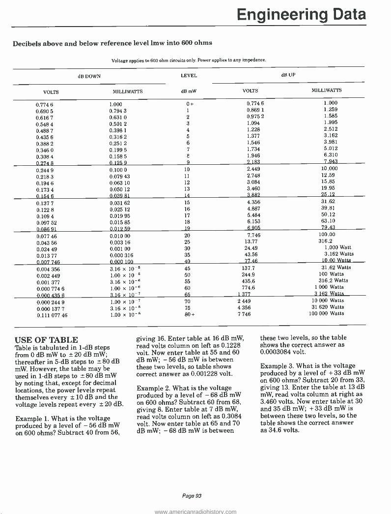
Engineering Data
Decibels above and below reference level lmw into 600 ohms
Voltage applies to 600 ohm circuits only. Power applies to any impedanm
dB DOWN LEVEL dB UP
VOLTS MILLIWATTS dB mW VOLTS MILLIWATTS
0.774 6 1.000 0+ 0.774 6 1.000
0.690 5 0.794 3 1 0.869 1 1.259
0.616 7 0.631 0 2 0.975 2 1.585
0.548 4 0.501 2 3 1.094 1.995
0.488 7 0.398 1 4 1.228 2.512
0.435 6 0.316 2 5 1.377 3.162
0.388 2 0.251 2 6 1.546 3.981
0.346 0 0.199 5 7 1.734 5.012
0.308 4 0.158 5 E 1.946 6.310
0.274 8 0.125 9 9 2.183 7.943
0.244 9 0.100 0 10 2.449 10.000
0.218 3 0.079 43 11 2.748 12.59
0.194 6 0.063 10 12 3.084 15.85
0.173 4 0.050 12 13 3.460 19.95
0.154 6 0.039 81 14 3.882 25.12
0.137 7 0.031 62 15 4.356 31.62
0.122 8 0.025 12 16 4.887 39.81
0.109 4 0.019 95 17 5.484 50.12
0.097 52 0.015 85 18 6.153 63.10
0.086 91 0.012 59 19 6.905 79.43
0.077 46 0.010 00 20 7.746 100.00
0.043 56 0.003 16 25 13.77 316.2
0.024 49 0.001 00 30 24.49 1.000 Watt
0.013 77 0.000 316 35 43.56 3.162 Watts
0.007 746 0.000 100 40 77.46 10.00 Watts
0.004 356 3.16 x 10⁻⁵ 45 137.7 31.62 Watts
0.002 449 1.00 X 10⁻⁵ 50 244.9 100 Watts
0.001 377 3.16 x 10⁻⁸ 55 435.6 316.2 Watts
0.000 774 6 1.00 x 10⁻⁸ 60 774.6 1 000 Watts
0.000 435 6 3.16 x 10⁻⁷ 65 1 377 3 162 Watts
0.000 244 9 1.00 x 10-' 70 2 449 10 000 Watts
0.000 137 7 3.16 x 10-e 75 4 356 31 620 Watts
0.111 077 46 1.00 x 10⁻⁸ 80 + 7 746 100 000 Watts
USE OF TABLE Table is tabulated in 1 -dB steps from 0 dB mW to ± 20 dB mW; thereafter in 5 -dB steps to ± 80 dB mW. However, the table may be used in 1 -dB steps to ± 80 dB mW by noting that, except for decimal locations, the power levels repeat themselves every ± 10 dB and the voltage levels repeat every ± 20 dB.
Example 1. What is the voltage produced by a level of - 56 dB mW on 600 ohms? Subtract 40 from 56,
giving 16. Enter table at 16 dB mW, read volts column on left as 0.1228 volt. Now enter table at 55 and 60 dB mW; - 56 dB mW is between these two levels, so table shows correct answer as 0.001228 volt.
Example 2. What is the voltage produced by a level of - 68 dB mW on 600 ohms? Subtract 60 from 68, giving 8. Enter table at 7 dB mW, read volts column on left as 0.3084 volt. Now enter table at 65 and 70 dB mW; - 68 dB mW is between
Page 93
these two levels, so the table shows the correct answer as 0.0003084 volt.
Example 3. What is the voltage produced by a level of + 33 dB mW on 600 ohms? Subtract 20 from 33, giving 13. Enter the table at 13 dB mW, read volts column at right as 3.460 volts. Now enter table at 30 and 35 dB mW; + 33 dB mW is between these two levels, so the table shows the correct answer as 34.6 volts.
www.americanradiohistory.com

Engineering Data
Forward VS Reflected Power
100KW 1000W
50KW 500W
10KW 100W
5KW 50W
1KW 10W
0.5KW 5W
0.1KW 1W
POWER _--,;,, SWR
\/REFLECTED EIII /I,' 1+ FORWARD POWER
1- /REFLECTED POWER V FORWARD POWER
SWR VALUES SHOWN AT LINES mv MIME
MEE 'AGM
,;
111111111119/11111111111
MiP,211MMErdinini
PPrlifireMPP 44.1041 , /0041 id
IOW
IKW
50W I OO W
5KW 10KW
FORWARD POWER
Page 94
500W 1000W
50KW I00KW
www.americanradiohistory.com

Engineering Data
Attenuator Network
J
FIN si
iiiiii
.
l
Fm R2
]
.
P1 x
Impedance 600 Ohms 600 Ohms 600 Ohms 600 Ohms 600 Ohms 600 Ohms 6000hms
Loss, dB R1 Ohms R2 Ohms R1 Ohms R2 Ohms R1 Ohms R2 Ohms R1 Ohms R2 Ohms Ri Ohms R2 Ohms R1 Ohms R2 Ohms R1 Ohms R2 Ohms
o 0.1 0.2 0.3 0.4
o 3.58 6.82
10.32 13.79
50204 26280 17460 13068
o 1.79 3.41 5.16 6.90
50204 26280 17460 13068
o 7.20
13.70 20.55 27.50
= 100500 57380 34900 26100
0 3.60 6.85
10.28 13.80
= 100500 57380 34900 26100
0 3.58 6.82
10.32 13.79
= 100500 57380 34900 26100
0 7.2
13.8 21.0 28.2
= 50000 26086 17143 12766
0 3.6 6.9
10.5 14.1
50000 26086 17143 12766
0.5 17.20 10464 8.60 10464 34.40 20920 17.20 20920 17.20 20920 35.4 10169 17.7 10169 0.6 20.9 8640 10.45 8640 41.7 17230 20.85 17230 20.9 17230 43.2 8333 21.6 8333 0.7 24.2 7428 12.1 7428 48.5 14880 24.25 14880 24.2 14880 50.4 7143 25.2 7143 0.8 27.5 6540 13.75 6540 55.05 13100 27.53 13100 27.5 13100 57.6 6250 28.8 6250 0.9 31.02 5787 15.51 5787 62.3 11600 31.2 11600 31.02 11000 65.4 5504 32.7 5504
1.0 34.5 5208 17.25 5208 68.6 10440 34.3 10440 34.5 10440 73.2 4918 36.6 4918 1.5 51.8 3452 25.9 3452 104.3 6950 52.1 6950 51.8 6950 113.4 3174 56.7 3174 2.0 68.8 2582 34.4 2582 139.4 5232 69.7 5232 68.8 5232 155.4 2310 77.7 2316 2.5 85.9 2053 42.9 2053 175.4 4195 87.7 4195 85.9 4195 200.4 1796 100.2 1796 3.0 102.7 1703 51.3 1703 212.5 3505 106,2 3505 102 7 3505 247 8 1452 123.0 1452
3.5 119.2 1448 59.6 1448 258.0 3021 120.0 3021 119.2 3021 297.6 1209 148.8 1209 4.0 135.8 1249 67.9 1249 287.5 2651 143.8 2051 135.8 2651 351.0 1025 175.5 1025 4.5 152.2 1109 76.1 1109 324.6 2365 162.3 2365 152.2 2365 407.8 883.7 203.7 883.7 5.0 168.1 987.6 84.1 987.6 364.5 2141 182.3 2141 1681 2141 466.8 771.2 233.4 771.2 5.5 184.0 886.8 92.0 886.8 405.9 1956 203.0 1956 184.0 1956 530.4 678.7 265.2 678.7 6.0 199.3 803.4 99.7 803.4 447.5 1807 223.8 1807 199.3 1807 597.0 693.0 298.6 603.0 6.5 214.6 730.8 107.3 730.8 492.6 1679 246.3 1679 214 6 1679 667.8 539.8 333.0 539.8 7.0 229.7 685.2 114.8 685.2 537.0 1569 268.5 1569 229.7 1569 743.4 484.3 371.7 484.3 7.5 244.2 615.6 122.1 615.6 584.7 1475 292.4 1475 244.2 1475 822.0 437.0 411.3 437.6 8.0 258.4 567.6 129.2 567.6 634.2 1393 317.1 1393 258.4 1393 907.2 396.8 453.6 396.8 8.5 272.3 525.0 136.1 525.0 685.5 1322 342.8 1322 272.3 1322 996.6 361.2 498.3 361.2 9.0 285.8 487.2 142.9 487.2 738.9 1260 369.4 1260 285.8 1260 1091 329.9 545.5 329.9 9.5 298.9 453.0 149.5 453.0 794.4 1204 397.2 1204 298.9 1204 1191 302.2 595.5 302.2
10.0 312.0 421.6 156.0 421.6 854.1 1154 427.0 1154 312.0 1154 1297 277.5 618.5 277.5 11.0 336.1 367.4 168.1 367.4 979.8 1071 489.9 1071 336.1 1071 1529 235.5 704.5 235.5 12.0 359.1 321.7 179.5 321.7 1119 1002 550.5 1002 359.1 1002 1788 201.3 804 201.3 13.0 380.5 282.8 190.3 282.8 1273 946.1 636.3 946.1 380.5 946.1 2080 173.1 1040s 173.1 14.0 400.4 249.4 200.2 249.4 1443 899.1 721.5 899.1 400.4 899.1 2407 149.6 1204 149.6 15.0 418.8 220.4 209.4 220.4 1632 859.6 816.0 859.6 418.8 859.6 2773 129.8 1387 129.8 16.0 435.8 195,1 217.9 195.1 1847 826.0 923,2 826.0 435.8 826.0 3186 113.0 1598 113.0 17.0 451.5 172.9 225.7 172.9 2083 797.3 1042 797.3 451.5 797.3 3648 98.68 1824 98.68 18.0 465.8 152.5 232.9 152.5 2344 772.8 1172 772.8 465.8 772.8 4166 86.4 2083 86.4 19.0 479.0 136.4 239.5 136.4 2670 751.7 1335 751.7 479.0 751.7 4748 75.8 2374 75.8 20.0 490.4 121.2 245.2 121.2 2970 733.3 1485 733.3 490.4 733.3 5400 66.66 2700 66.66 22.0 .511.7 95.9 255.9 95.9 3753 703.6 1877 703.6 511.7 703.6 6954 51,72 3477 51.72 24.0 528.8 76.0 264.4 76.0 4737 680.8 2369 680.8 528.8 680.8 8910 40.4 4455 40.4 26.0 542.7 60.3 271.4 60.3 5985 663.4 2992 663.4 542.7 663.4 11370 34.66 5685 31.66 28.0 554.1 47.8 277.0 47.8 7550 649.7 3775 649.7 554.1 649.7 14472 24.87 7236 24.87 30.0 563.0 37.99 281.0 37.99 9500 639.2 4750 639.2 563.2 639.2 18372 19.58 9186 19.58 32.0 570.6 30.16 285.3 30.16 11930 630.9 5967 630.9 570.6 630.9 23286 15.46 11643 15.46 34.0 576.5 23.95 288.3 23.95 15000 624.4 7500 624.4 576.5 624.4 29472 12.21 14736 12.21 36.0 581.1 18.98 290.6 18.98 18960 619.3 9480 619.3 581.1 619.3 37200 9.66 18630 9.66 38.0 585.1 15.11 292.5 15.11 23820 615.3 11910 615.3 585.1 615.3 47058 7.65 23529 7.05 40.0 588.1 12.00 294.1 12.00 30000 6121 15000 612.1 588.1 612.1 59400 6.06 29700 6.06
Volume Level to Power and Voltage Conversion
REFERENCE LEVEL: 0 DBM = 1 MW, 600 OHMS
MILLIWATTS VOLTS DBM WATTS VOLTS DBM
0.000001 0.0007746 - 60 0.001000 0.7746 0 0.000010 0.002449 - 50 0.002512 1.228 + 4 0.000100 0.007746 - 40 0.006310 1.946 + 8 0.001 0.02449 - 30 0.01000 2.449 + 10 0.010 0.07746 - 20 0.1000 7.746 + 20 0.100 0.2449 - 10 1.000 24.49 + 30 1.000 0.7746 0 10.00 77.46 + 40
Page 95
www.americanradiohistory.com

Engineering Data Frequencies Used for Standard Broadcast Stations
The band 535 -1605 kHz is used for standard broadcasting. It is divided into 107 channels of 10 kHz
Channel 540 550 560 570 580 590 600 610 620 630 640
650 660 670 680 690
700 710 720 730 740 750 760 770 780 790 800 810 820 830 840 850 860 870 880 890 900 910 920 930 940 950 960 970 980 990
1000 1010 1020 1030
Classification Clear Regional Regional Regional Regional Regional Regional Regional Regional Regional Clear
Clear Clear Clear Clear Clear
Clear Clear Clear Clear Clear Clear Clear Clear Clear Regional Clear Clear Clear Clear Clear Clear Clear Clear Clear Clear Clear Regional Regional Regional Clear Regional Regional Regional Regional Clear Clear Clear Clear Clear
each. Following is a list of standard broadcast channels and the conditions under which each may be used in the United States. For
further reference and additional information, see FCC Rules, and the 1950 North American Regional Broadcast Agreement.
Use Under FCC Rules II III -A, III -B III -A, III -B III -A, III -B III -A, III -B III -A, III -B III -A, III -B III -A, III -B III -A, III -B III -A, III -B I, II
I, II I, II I, II I, II
II
I, II I, II I, II II
II
I, II I, II I, II I, II III -A, III -B II I, II I, II I, II I, II I, II II
I, II I, II I, II II
III -A, III -B III -A, III -B III -A, III -B I, II III -A, III -B III -A, III -B III -A, III -B III -A, III -B II I, II II I, II I, II
NARBA Class I Priority Canada (I -A) Mexico (I -A) Cuba (I -C)
Cuba (I -D)
Page 96
Cuba (I-D)
Dominican Republic (I -C) Cuba (I -D) USA (I -A) Canada (I-C)
Cuba (I -C) USA (I -A) USA (I-A) USA (I -A) USA (I -B) Canada (I -A) Cuba (I -C)
Mexico (I -B) USA (I -A) USA (I -B) USA (I -A) Mexico (I -A) Canada (I -A) Cuba (I -D) USA (I -A) USA (I -A) USA (I-A) USA (I -A)
Mexico (I -A) USA (I -B) USA (I-A) USA (I -A) USA (I -A) USA (I -B) Mexico (I -B) Canada (I -A) Cuba (I -C) USA (I -A) USA (I -A) USA (I-A) Mexico (I -A)
Cuba (I -D)
Canada & Mexico (I -B) Cuba (I -D)
Cuba (I -D) Canada (I-A) Mexico & USA (I -B) Canada (I -A) Cuba (I -B) USA (I -A) USA (I -A)
www.americanradiohistory.com

Engineering Data
Use Under Channel Classification NARBA Class I Priority FCC Rules
1040 Clear USA (I -A) I, II 1050 Clear Mexico (I -A) II 1060 Clear Mexico & USA (I -B) I, II 1070 Clear Canada & USA (I -B) I, II 1080 Clear USA (I -B) I, II 1090 Clear Mexico & USA (I -B) I, II 1100 Clear USA (I -A) I, II 1110 Clear USA (I -B) I, II 1120 Clear USA (I -A) I, II 1130 Clear Canada & USA (I -B) I, II 1140 Clear Mexico & USA (I -B) I, II 1150 Regional III -A, III -B 1160 Clear USA (I -A) I, II 1170 Clear USA (I -B) I, II 1180 Clear USA (I -A) I, II 1190 Clear Mexico & USA (I -B) I, II 1200 Clear USA (I -A) I, II 1210 Clear USA (I -A) I, II 1220 Clear Mexico (I -A) II 1230 Local IV 1240 Local IV 1250 Regional III -A, III -B 1260 Regional III -A, III -B 1270 Regional III -A, III -B 1280 Regional III -A, III -B 1290 Regional III -A, III -B 1300 Regional III -A, III -B 1310 Regional III -A, III -B 1320 Regional III -A, III -B 1330 Regional III -A, III -B 1340 Local IV 1350 Regional III -A, III -B 1360 Regional III -A, III -B 1370 Regional III -A, III -B
1380 Regional III -A, III -B 1390 Regional III -A, III -B 1400 Local IV 1410 Regional III -A, III -B 1420 Regional III -A, III -B 1430 Regional III -A, III -B 1440 Regional III -A, III -B 1450 Local IV 1460 Regional III -A, III -B 1470 Regional III -A, III -B 1480 Regional III -A, III -B 1490 Local IV 1500 Clear USA (I -B) I, II 1510 Clear USA (I -B) I, II 1520 Clear USA (I -B) I, II 1530 Clear USA (I -B) I, II 1540 Clear Bahamas (I -A) USA (I -B) II 1550 Clear Canada & Mexico (I -B) I, II 1560 Clear USA & Cuba (I -B) I, II 1570 Clear Mexico (I -A) II 1580 Clear Canada (I -A) II 1590 Regional III -A, III -B 1600 Regional III -A, III -B
Page 97
www.americanradiohistory.com

Engineering Data
Frequency Designation of FM 90.9 215 100.9 265 94.5 233 104.5 283 Broadcast Channels 91.1 216 101.1 266 94.7 234 104.7 284 Freq. Channel Freq. Channel 91.3 217 101.3 267 94.9 235 104.9 285 (MHz) No. (MHz) No. 91.5 218 101.5 268 95.1 236 105.1 286 88.1 201 98.1 251 91.7 219 101.7 269 95.3 237 105.3 287 88.3 202 98.3 252 91.9 220 101.9 270 95.5 238 105.5 288 88.5 203 98.5 253 92.1 221 102.1 271 95.7 239 105.7 289 88.7 204 98.7 254 92.3 222 102.3 272 95.9 240 105.9 290 88.9 205 98.9 255 92.5 223 102.5 273 96.1 241 106.1 291 89.1 206 99.1 256 92.7 224 102.7 274 96.3 242 106.3 292 89.3 207 99.3 257 92.9 225 102.9 275 96.5 243 106.5 293 89.5 208 99.5 258 93.1 226 103.1 276 96.7 244 106.7 294 89.7 209 99.7 259 93.8 227 103.3 277 96.9 245 106.9 295 89.9 210 99.9 260 93.5 228 103.5 278 97.1 246 107.1 296 90.1 211 100.1 261 93.7 229 103.7 279 97.3 247 107.3 297 90.3 212 100.3 262 93.9 230 103.9 280 97.5 248 107.5 298 90.5 213 100.5 263 94.1 231 104.1 281 97.7 249 107.7 299 90.7 214 100.7 264 94.3 232 104.3 282 97.9 250 107.9 300
Decibels Vs Ratio
6DB 3DB
80
70
60
50
40
30
20
10
0
1
2 4 6 8
10
4 68 2 4 68 2 4 68 100 1000 10,000
RATIO
Page 98
www.americanradiohistory.com

Classes of FM Stations, FCC 80 -90 Docket Engineering Data
The following table is offered as a general guide to the classes of FM radio broadcast stations brought about by the FCC 80 -90 docket. For specific interpretation and equipment requirements, see your engineering consultant.
Required Transmitter Power Out " Antenna
Bays
Effective Coax Radiated Line Power " Size
Coax Line
Length
Coax Line
Efficiency Tower
Height "
Class A FM - 328 Feet
7.6 kW 1 3 kW 1 -5/8" 328' 85.0% 328' 3.6 kW ' 2 3 kW 1 -5/8" 342' 85.2% 333' 2.3 kW ' 3 3 kW 1 -5/8" 347' 85.4% 337'
Class A FM - 500 Feet
2.8 kW 1 1 kW 1 -5/8" 519' 78.4% 500' 1.3 kW ' 2 1 kW 1 -5/8" 514' 78.6% 505' 0.8 kW 2 1 kW 1 -5/8" 509' 78.7% 510'
Class B1 FM - 328 Feet
13.0 kW 4 25 kW 3" 332' 89.6% 343' 10.3 kW 5 25 kW 3" 327' 89.8% 348' 8.4 kW 6 25 kW 3" 322' 89.9% 353' 7.1 kW 7 25 kW 3" 317' 90.1% 358' 6.2 kW ' 8 25 kW 3" 313' 90.2% 363'
Class B or C2 FM - 492 Feet 21.7 kW 5 50 kW 3" 491' 85.1% 512' 17.8 kW 6 50 kW 3" 486' 85.2% 517' 15.1 kW 7 50 kW 3" 481' 85.3% 522' 13.0 kW ' 8 50 kW 3" 477' 85.4% 527' 11.6 kW 9 50 kW 3" 511' 85.5% 532' 10.4 kW 10 50 kW 3" 511' 85.5% 537'
Class C1 FM - 984 Feet 39.1 kW 6 100 kW 3-1/8" 1,003' 77.4% 1,009' 28.8 kW 8 100 kW 3-1/8" 1,003' 77.4% 1,019' 24.5 kW ' 10 100 kW 3" 1,003' 71.8% 1,029' 20.2 kW 12 100kW 3" 1,003' 71.8% 1,039'
Class C FM - 1,968 Feet 51.4 kW 6 100 kW 4" 1,987' 58.9% 1,993' 37.8 kW 8 100 kW 4" 1,987' 58.9% 2,003' 29.2 kW ' 10 100 kW 3 -1/8" 1,987' 60.2% 2,013' 20.2 kW 12 100 kW 3" 1,987' 51.9% 2,023'
Most commonly requested antenna transmitter combinations. (Even number of bays required for beam tilt and null fill)
Shown with maximum effective radiated power (e.r.p.) and maximum height allowed.
Page 99
www.americanradiohistory.com

Engineering Data
Footage Table for Broadcast Tower Heights
KHZ
550 KHZ TO 1070 KHZ
METERS 1 WAVE 1 WAVE 1 WAVE KHZ
1080 KHZ TO 1600 KHZ
METERS 1 WAVE 1 WAVE V WAVE
550 545 1787.6 893.8 446.8 1080 277.8 911.1 455.5 227.7
560 536 1758.0 879.0 439.5 1090 275.2 902.6 451.3 225.6
570 526 1725.3 862.6 431.3
580 517 1695.7 847.8 423.9 1100 272.7 894.4 447.2 223.6
590 509 1669.5 834.7 417.3 1110 270.3 886.5 443.2 221.6
1120 267.9 879.0 439.5 219.7
600 500 1640.0 820.0 410.0 1130 265.5 870.8 435.4 217.7
610 492 1612.7 806.3 403.1 1140 263.2 862.6 431.3 215.6
620 484 1587.5 799.7 396.8 1150 260.9 855.7 427.8 213.9
630 476 1561.2 780.6 390.3 1160 258.6 847.8 423.9 211.9
640 469 1546.3 773.1 386.5 1170 256.4 840.9 420.4 210.2
650 462 1515.3 757.6 378.8 1180 254.2 834.7 417.3 208.6
660 455 1492.4 746.2 373.1 1190 252.1 826.8 413.4 206.7
670 448 1469.4 734.7 367.3
680 441 1446.4 723.2 361.1 1200 250.0 820.0 410.0 205.0
690 435 1426.4 713.2 361.2 1210 247.9 813.1 406.5 203.2
1220 245.9 806.3 403.1 201.5
700 429 1407.1 703.5 351.2 1230 243.9 799.1 399.5 199.7
710 423 1387.4 693.7 346.8 1240 241.9 793.7 396.8 198.4
720 417 1367.7 683.8 341.9 1250 240.0 787.2 393.6 196.8
730 411 1348.0 674.0 337.0 1260 238.1 780.9 390.4 195.2
740 405 1328.4 664.2 332.1 1270 236.2 774.7 387.3 193.6
750 400 1312.0 656.0 328.0 1280 234.4 768.8 384.4 192.2
760 395 1295.6 647.8 323.4 1290 232.6 762.9 381.4 190.7
770 390 1279.2 639.6 319.8
780 385 1262.8 631.4 315.7 1300 230.8 757.0 378.5 189.2
790 380 1246.4 623.2 311.6 1310 299.0 751.1 375.5 187.7
1320 227.3 746.2 373.1 186.5
800 375 1230.0 615.0 307.5 1330 225.6 739.9 369.9 184.9
810 370 1213.6 606.8 303.4 1340 223.9 734.7 367.3 183.6
820 366 1200.4 600.2 300.1 1350 222.2 728.8 364.4 182.2
830 361 1184.0 592.0 296.0 1360 220.6 723.2 361.1 180.5
840 357 1170.9 585.4 292.7 1370 219.0 718.3 359.1 179.5
850 353 1157.8 578.9 289.4 1380 217.4 713.4 356.2 178.1
860 349 1144.7 572.3 286.1 1390 215.8 707.8 353.1 176.5
870 345 1131.6 565.8 282.9
880 341 1118.4 559.2 279.6 1400 214.3 703.5 351.2 175.6
890 337 1105.3 552.6 276.3 1410 212.8 696.9 348.4 174.2
1420 211.3 693.7 346.8 173.4
900 333 1092.2 546.1 273.0 1430 209.8 688.1 344.0 172.0
910 330 1082.4 541.2 270.6 1440 208.3 683.8 341.9 170.9
920 326 1069.2 534.6 267.3 1450 206.9 678.6 339.3 169.6
930 323 1059.4 529.7 264.8 1460 205.5 674.0 337.0 168.5
940 319 1046.3 523.1 261.5 1470 204.1 669.4 334.7 167.3
950 316 1036.4 518.2 259.1 1480 202.7 664.2 332.1 166.5
960 313 1026.6 513.3 256.6 1490 201.3 660.2 330.1 165.0
970 309 1013.5 506.7 253.3
980 306 1003.6 501.8 250.9 1500 200.0 656.0 328.0 164.0
990 303 993.8 496.9 248.4 1510 198.7 651.7 325.8 162.9
1520 197.4 647.8 323.4 161.7
1000 300 984.0 492.0 246.0 1530 196.1 643.2 321.6 160.8
1010 297 974.1 487.5 243.7 1540 194.8 639.6 319.8 159.9
1020 294.1 964.6 482.3 241.1 1550 193.5 634.6 317.3 158.6
1030 291.3 955.3 477.6 238.8 1560 192.3 631.4 315.7 157.8
1040 288.5 946.2 473.1 236.5 1570 191.1 626.8 313.4 156.7
1050 285.7 937.1 468.5 234.2 1580 189.9 623.2 311.6 155.8
1060 283.0 928.2 464.1 232.0 1590 188.7 618.9 309.4 154.7
1070 280.4 919.7 459.8 229.9
1600 187.6 615.0 307.5 153.7
Page 100
www.americanradiohistory.com

Engineering Data
LA
TIH i VN
W X 4 Z Z W H Z Q
N) _ W
CIL
Q > .
0 Li. Ln W J V ^
Z 4 Z O N L . uai CI
Z Q
4 o v1
0 Z
W L.) W CIL
i/
N W J
W V
Q N) -
g u,W N J
r
®
J_
2 =
Z Q Ñ
o
on
vo c `a O O N
-O H D
v' O
É >
x O O
á á a°; ° vt
N O C > O Ol
= *O
(V O
'
= II
C Ñ j
'0 L O L ..- t 4,0 'O V m c or) t 0 '
1 r Q
ñ,
rn C O
O n
c O N
O
O) C
O C
r, a) i
d o I
--
<
Y
C 4 O
7»
Y
Y °
o
^
o
e-
N
o
0
P
*co
n
° O
o on
N V
o O
o N ri
°,1
o
ri
e H I
o
^
o
^
¡n O
f o
.ri
O
N ^ o
m
o
0
N N o
f N O
N. N
r)
in r) O
r) a o
m a O
f v1
'O
n O
'O m O
O h ^
a .-
N
'O f
0
r1 N O
v1 N o
n N ó
0
CI Pf 0
N. r) O
^ f o
O f O
v1 h O
a 'O o
^ P O
O m
N P O
p .-
0 m
^
^D N
ri r7
N r
P N o
- P) O
n I.1 o
O en
ó
0
C a 0
P f O
d v, O
co
'O O
r) n O
m o
a O' o
O O ^
a N ^
a ^
v1 n
CO
N
00'
N
Q f
P P
O r Ò
P C'1
O
N a o
v1 a 0
0
v) v1
0
^ 'O O
m d O
CO n O
N O. O
O - ^ N ^
'O
^
h v1
^
m ^
'O ^ N
N r N
wl 'O r)
C vi
'O ^
r) f o
'O a O
0 v1
Ò
f .ro
0
P
v1 'O 0
r) r. O
^ m o
N O.
o
O
r1
^
N f ̂ r)
^
'O m ^
in ^ N
f 'O N
.- O
r)
m a
CO
O
O o
O v o
r) h O
r' v1
o
N C ò
m
a h o
r) CO
O
a P O
O O
N ^
p M n-
m 'O .-
O O' ^
'O
N
vl N
m O r)
r CO
r)
N v1
P F:
P P
CO h o
^ O O
N o Ò
N n 0
m
..co m O
n P O
v1 O ^
N N ^
v1 ^
r` ^
O P .-
h ^
O v1
N
m N
fN v1 r)
P f
P v1
N P
N ñ
v1 O o
P .O
O
h N O
^ CO
ò
m
r` P o
P 0 ^
P ^ ^
'0 r) ^
N o
P .-
r) ^ N
v1 a N
O m N
N r)
m P r)
h O v1
n 'O
v1
O
v1
C. h o
N N O
en CO
o
O P o
co
CO O ^
^
N (7 ^
N h
P N.
N
P r) N
O n Na
O
r)
'O r)
P r) a
^ vl
f n
'O
^
N
n m o
N P O
O o
CO O ^
m
P N ^
a f ^
P h ^
m
VI ^ N
'O N
v) m N
P ^
^ r)
P
a
h
h r .p
o P
p O ^
'O O
v1
f N ^
0
vl f ^
r) O ^
vt CO
^
.-
m a N
Ó r)
v1 r) r)
h h
r) r)
d
, ^ r Na ^ 'O
'O O r.
a O
r,
I
O
^
N
N
f a
vl
N r` ^
P ^
In ^ N
O a r:
a m N
d M
O m O
v1 r) a
N O v1
c0 vl
41
O
n
O
P
O Ni
a
`
I
O r) ^
m f 1
m
N O ^
v1
d P, ^
vt
N
P fh N
O' O r;
P ^ r)
P r)
O r) d
O P f v1 'O
vi
p 'O 'O
O O m
v N O
'O ^
r)
fNV
I
O a ^
'O .1
o
in CO
^
O
el
N
m r) N
CO "O
N
a 0 n
O 'o r)
r) V
O m a
v1 f vi
v) N 'O
t") r.
P m m
v1 N ¡
a h
f fV
o A r)
f CO
rf
r ^ a
O vt a
O
O d
O O '0
f'1 n 'O
h n n
0 P
O ^ ^
v1 n Cl
^
N. m
O m N N
vt P N
P N a
i
I
I..
=
X O O
0 I o a Ñ C
- -O y
6) L
- 0 V
LV
C 0.)
r0
`~ O
Ç O
s O1 a)
C = ú
I I
G t
0 °
'O ^ N
o O r1
m O N
v1 a N
a o r
r) m N
á r)
o ^ n
h n r)
'o a r)
v', o a
A n
r en f
O
g
N h f
a N f
n m a
o N f
O n 41
0 P a
n n 41
0 r) r
O N O
'O 'O r
O
o p 'O
r) CO
'
N r) 'O
O mo
O O O
)aaj L+i
016!014 = o Ñ
O c0')
pop
Y ó h
O '00
o ñ 8
O P
$ ó
o N
O O
ó O
m
0 cov
0 voi
Page 101
www.americanradiohistory.com
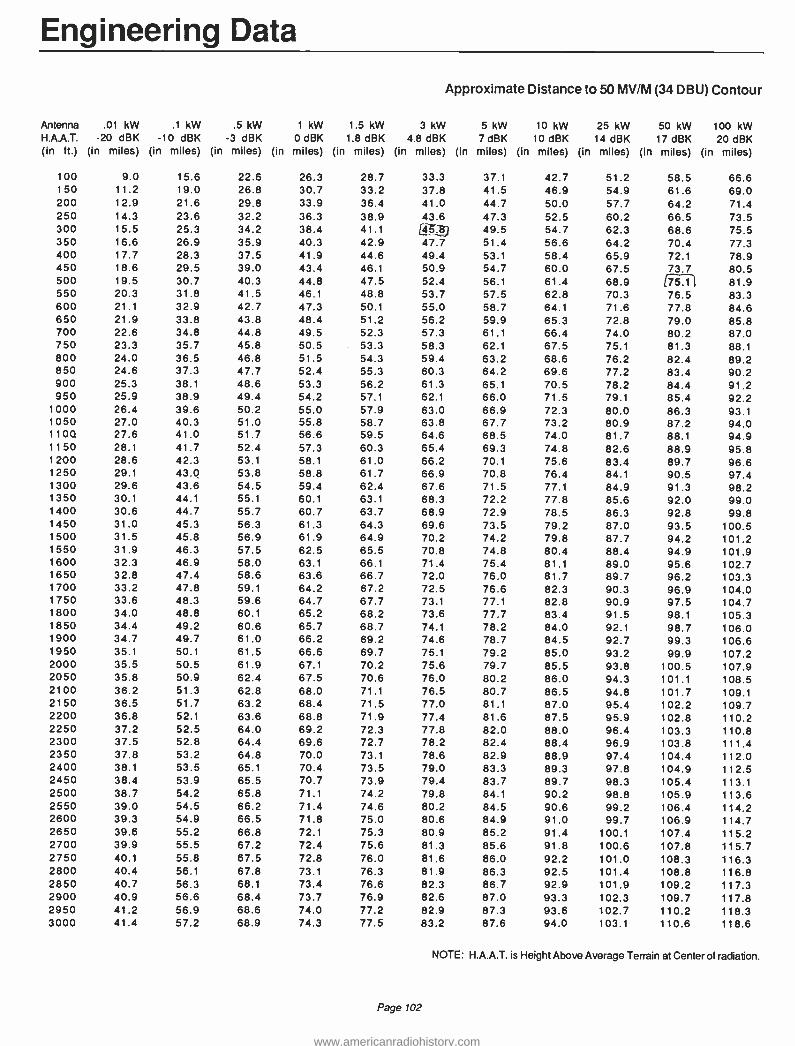
Engineering Data
Approximate Distance to 50 MV /M (34 DBU) Contour
Antenna H.A.A.T. (in ft.)
.01 kW -20 dBK
(in miles)
.1 kW -10 dBK
(in miles)
.5 kW -3 dBK
(in miles)
1 kW 0 dBK
(in miles)
1.5 kW 1.8 dBK
(in miles)
3 kW 4.8 dBK
(in miles)
5 kW 7 dBK
(in miles)
10 kW 10 dBK
(in miles)
25 kW 14 dBK
(in miles)
50 kW 17 dBK
(in miles)
100 kW 20 dBK
(in miles)
100 9.0 15.6 22.6 26.3 28.7 33.3 37.1 42.7 51.2 58.5 66.6 150 11.2 19.0 26.8 30.7 33.2 37.8 41.5 46.9 54.9 61.6 69.0 200 12.9 21.6 29.8 33.9 36.4 41.0 44.7 50.0 57.7 64.2 71.4 250 14.3 23.6 32.2 36.3 38.9 43.6 47.3 52.5 60.2 66.5 73.5 300 15.5 25.3 34.2 38.4 41.1 (45.8) 49.5 54.7 62.3 68.6 75.5 350 16.6 26.9 35.9 40.3 42.9 47.7 51.4 56.6 64.2 70.4 77.3 400 17.7 28.3 37.5 41.9 44.6 49.4 53.1 58.4 65.9 72.1 78.9 450 18.6 29.5 39.0 43.4 46.1 50.9 54.7 60.0 67.5 73.7 80.5 500 19.5 30.7 40.3 44.8 47.5 52.4 56.1 61 .4 68.9 (75.1-, 81.9 550 20.3 31.8 41.5 46.1 48.8 53.7 57.5 62.8 70.3 76.5 83.3 600 21.1 32.9 42.7 47.3 50.1 55.0 58.7 64.1 71.6 77.8 84.6 650 21.9 33.8 43.8 48.4 51.2 56.2 59.9 65.3 72.8 79.0 85.8 700 22.6 34.8 44.8 49.5 52.3 57.3 61.1 66.4 74.0 80.2 87.0 750 23.3 35.7 45.8 50.5 53.3 58.3 62.1 67.5 75.1 81.3 88.1 800 24.0 36.5 46.8 51.5 54.3 59.4 63.2 68.6 76.2 82.4 89.2 850 24.6 37.3 47.7 52.4 55.3 60.3 64.2 69.6 77.2 83.4 90.2 900 25.3 38.1 48.6 53.3 56.2 61.3 65.1 70.5 78.2 84.4 91.2 950 25.9 38.9 49.4 54.2 57.1 62.1 66.0 71.5 79.1 85.4 92.2
1000 26.4 39.6 50.2 55.0 57.9 63.0 66.9 72.3 80.0 86.3 93.1 1050 27.0 40.3 51.0 55.8 58.7 63.8 67.7 73.2 80.9 87.2 94.0 1104 27.6 41.0 51.7 56.6 59.5 64.6 68.5 74.0 81.7 88.1 94.9 1150 28.1 41.7 52.4 57.3 60.3 65.4 69.3 74.8 82.6 88.9 95.8 1200 28.6 42.3 53.1 58.1 61.0 66.2 70.1 75.6 83.4 89.7 96.6 1250 29.1 43.0 53.8 58.8 61.7 66.9 70.8 76.4 84.1 90.5 97.4 1300 29.6 43.6 54.5 59.4 62.4 67.6 71.5 77.1 84.9 91.3 98.2 1350 30.1 44.1 55.1 60.1 63.1 68.3 72.2 77.8 85.6 92.0 99.0 1400 30.6 44.7 55.7 60.7 63.7 68.9 72.9 78.5 86.3 92.8 99.8 1450 31.0 45.3 56.3 61.3 64.3 69.6 73.5 79.2 87.0 93.5 100.5 1500 31.5 45.8 56.9 61.9 64.9 70.2 74.2 79.8 87.7 94.2 101.2 1550 31.9 46.3 57.5 62.5 65.5 70.8 74.8 80.4 88.4 94.9 101.9 1600 32.3 46.9 58.0 63.1 66.1 71.4 75.4 81.1 89.0 95.6 102.7 1650 32.8 47.4 58.6 63.6 66.7 72.0 76.0 81.7 89.7 96.2 103.3 1700 33.2 47.8 59.1 64.2 67.2 72.5 76.6 82.3 90.3 96.9 104.0 1750 33.6 48.3 59.6 64.7 67.7 73.1 77.1 82.8 90.9 97.5 104.7 1800 34.0 48.8 60.1 65.2 68.2 73.6 77.7 83.4 91.5 98.1 105.3 1850 34.4 49.2 60.6 65.7 68.7 74.1 78.2 84.0 92.1 98.7 106.0 1900 34.7 49.7 61.0 66.2 69.2 74.6 78.7 84.5 92.7 99.3 106.6 1950 35.1 50.1 61.5 66.6 69.7 75.1 79.2 85.0 93.2 99.9 107.2 2000 35.5 50.5 61.9 67.1 70.2 75.6 79.7 85.5 93.8 100.5 107.9 2050 35.8 50.9 62.4 67.5 70.6 76.0 80.2 86.0 94.3 101.1 108.5 2100 36.2 51.3 62.8 68.0 71.1 76.5 80.7 86.5 94.8 101.7 109.1 2150 36.5 51.7 63.2 68.4 71.5 77.0 81.1 87.0 95.4 102.2 109.7 2200 36.8 52.1 63.6 68.8 71.9 77.4 81.6 87.5 95.9 102.8 110.2 2250 37.2 52.5 64.0 69.2 72.3 77.8 82.0 88.0 96.4 103.3 110.8 2300 37.5 52.8 64.4 69.6 72.7 78.2 82.4 88.4 96.9 103.8 111.4 2350 37.8 53.2 64.8 70.0 73.1 78.6 82.9 88.9 97.4 104.4 112.0 2400 38.1 53.5 65.1 70.4 73.5 79.0 83.3 89.3 97.8 104.9 112.5 2450 38.4 53.9 65.5 70.7 73.9 79.4 83.7 89.7 98.3 105.4 113.1 2500 38.7 54.2 65.8 71.1 74.2 79.8 84.1 90.2 98.8 105.9 113.6 2550 39.0 54.5 66.2 71.4 74.6 80.2 84.5 90.6 99.2 106.4 114.2 2600 39.3 54.9 66.5 71.8 75.0 80.6 84.9 91.0 99.7 106.9 114.7 2650 39.6 55.2 66.8 72.1 75.3 80.9 85.2 91.4 100.1 107.4 115.2 2700 39.9 55.5 67.2 72.4 75.6 81.3 85.6 91.8 100.6 107.8 115.7 2750 40.1 55.8 67.5 72.8 76.0 81.6 86.0 92.2 101.0 108.3 116.3 2800 40.4 56.1 67.8 73.1 76.3 81.9 86.3 92.5 101.4 108.8 116.8 2850 40.7 56.3 68.1 73.4 76.6 82.3 86.7 92.9 101.9 109.2 117.3 2900 40.9 56.6 68.4 73.7 76.9 82.6 87.0 93.3 102.3 109.7 117.8 2950 41.2 56.9 68.6 74.0 77.2 82.9 87.3 93.6 102.7 110.2 118.3 3000 41.4 57.2 68.9 74.3 77.5 83.2 87.6 94.0 103.1 110.6 118.6
NOTE: H.A.A.T. is Height Above Average Terrain at Center of radiation.
Page 102
www.americanradiohistory.com

Engineering Data
Approximate Distance to .5 MV /M (54 DBU) Contour
Antenna H.A.A.T. (in ft.)
.01 kW -20 dBK
(in miles)
.1 kW -10 dBK
(in miles)
.5 kW -3 dBK
(in miles)
1 kW 0 dBK
(in miles)
1.5 kW 1.8 dBK
(in miles)
3 kW 4.8 dBK
(in miles)
5 kW 7 dBK
(in miles)
10 kW 10 dBK
(in miles)
25 kW 14 dBK
(in miles)
50 kW 17 dBK
(in miles)
100 kW 20 dBK
(in miles)
100 2.9 5.1 7.6 9.0 9.9 11.7 13.3 15.6 19.3 22.6 26.3 150 3.5 6.3 9.4 11.2 12.3 14.5 16.3 19.0 23.2 26.8 30.7 200 4.0 7.3 10.9 12.9 14.1 16.6 18.6 21.6 26.0 29.8 33.9 250 4.5 8.1 12.1 14.3 15.7 18.3 20.4 23.6 28.3 32.2 36.3 300 4.9 8.9 13.2 15.5 17.0 19.81 22.0 25.3 30.2 34.2 38.4 350 5.3 9.6 14.2 16.6 18.2 21.1 23.4 26.9 31.9 35.9 40.3 400 5.7 10.3 15.1 17.7 19.3 22.3 24.7 28.3 33.4 37.5 41.9 450 6.1 10.9 15.9 18.6 20.3 23.4 25.9 29.5 34.7 39.0 43.4 500 6.4 11.5 16.7 19.5 21.2 24.5 27.0 30.7 36.0 :40.3 44.8 550 6.7 12.0 17.5 20.3 22.1 25.4 28.0 31.8 37.2 41.5 46.1 600 7.0 12.6 18.2 21.1 23.0 26.3 29.0 32.9 38.3 42.7 47.3 650 7.3 13.1 18.9 21.9 23.8 27.2 29.9 33.8 39.4 43.8 48.4 700 7.6 13.6 19.5 22.6 24.5 28.1 30.8 34.8 40.4 44.8 49.5 750 7.8 14.0 20.2 23.3 25.3 28.9 31.7 35.7 41.3 45.8 50.5 800 8.1 14.5 20.8 24.0 26.0 29.6 32.5 36.5 42.2 46.8 51.5 850 8.4 14.9 21.4 24.6 26.7 30.4 33.2 37.3 43.1 47.7 52.4 900 8.6 15.3 21.9 25.3 27.3 31.1 34.0 38.1 43.9 48.6 53.3 950 8.8 15.8 22.5 25.9 28.0 31.7 34.7 38.9 44.8 49.4 54.2
1000 9.1 16.2 23.0 26.4 28.6 32.4 35.4 39.6 45.5 50.2 55.0 1050 9.3 16.6 23.5 27.0 29.2 33.1 36.1 40.3 46.3 51.0 55.8 1100 9.5 16.9 24.0 27.6 29.7 33.7 36.7 41.0 47.0 51.7 56.6 1150 9.7 17.3 24.5 28.1 30.3 34.3 37.3 41.7 47.7 52.4 57.3 1200 9.9 17.7 25.0 28.6 30.9 34.9 38.0 42.3 48.4 53.1 58.1 1250 10.1 18.0 25.5 29.1 31.4 35.4 38.6 43.0 49.0 53.8 58.7 1300 10.3 18.4 25.9 29.6 31.9 36.0 39.1 43.6 49.7 54.5 59.4 1350 10.5 18.7 26.4 30.1 32.4 36.5 39.7 44.1 50.3 55.1 60.1 1400 10.7 19.0 26.8 30.6 32.9 37.0 40.2 44.7 50.9 55.7 60.7 1450 10.9 19.4 27.2 31.0 33.4 37.6 40.8 45.3 51.5 56.3 61.3 1500 11.0 19.7 27.6 31.5 33.8 38.1 41.3 45.8 52.0 56.9 61.9 1550 11.2 20.0 28.0 31.9 34.3 38.5 41.8 46.3 52.6 57.5 62.5 1600 11.4 20.3 28.4 32.3 34.7 39.0 42.3 46.9 53.1 58.0 63.1 1650 11.6 20.6 28.8 32.8 35.2 39.5 42.8 47.4 53.6 58.6 63.6 1700 11.7 20.9 29.2 33.2 35.6 39.9 43.2 47.8 54.2 59.1 64.2 1750 11.9 21.2 29.6 33.6 36.0 40.4 43.7 48.3 54.7 59.6 64.7 1800 12.0 21.5 29.9 34.0 36.4 40.8 44.1 48.8 55.1 60.1 65.2 1850 12.2 21.7 30.3 34.4 36.8 41.2 44.6 49.2 55.6 60.6 65.7 1900 12.3 22.0 30.6 34.7 37.2 41.6 45.0 49.7 56.1 61.0 66.2 1950 12.5 22.3 31.0 35.1 37.6 42.0 45.4 50.1 56.5 61.5 66.6 2000 12.6 22.6 31.3 35.5 38.0 42.4 45.8 50.5 56.9 61.9 67.1 2050 12.8 22.8 31.6 35.8 38.3 42.8 46.2 50.9 57.4 62.4 67.5 2100 12.9 23.1 32.0 36.2 38.7 43.2 46.6 51.3 57.8 62.8 68.0 2150 13.1 23.3 32.3 36.5 39.1 43.6 47.0 51.7 58.2 63.2 68.4 2200 13.2 23.6 32.6 36.8 39.4 43.9 47.3 52.1 58.6 63.6 68.8 2250 13.3 23.8 32.9 37.2 39.7 44.3 47.7 52.5 59.0 64.0 69.2 2300 13.5 24.0 33.2 37.5 40.1 44.6 48.1 52.8 59.3 64.4 69.6 2350 13.6 24.3 33.5 37.8 40.4 45.0 48.4 53.2 59.7 64.8 70.0 2400 13.7 24.5 33.8 38.1 40.7 45.3 48.7 53.5 60.1 65.1 70.4 2450 13.8 24.7 34.1 38.4 41.0 45.6 49.1 53.9 60.4 65.5 70.7 2500 14.0 25.0 34.4 38.7 41.3 45.9 49.4 54.2 60.7 65.8 71.1 2550 14.1 25.2 34.6 39.0 41.6 46.2 49.7 54.5 61.1 66.2 71.4 2600 14.2 25.4 34.9 39.3 41.9 46.6 50.0 54.9 61.4 66.5 71.8 2650 14.3 25.6 35.2 39.6 42.2 46.9 50.3 55.2 61.7 66.8 72.1 2700 14.4 25.8 35.4 39.9 42.5 47.1 50.6 55.5 62.0 67.2 72.4 2750 14.5 26.0 35.7 40.1 42.8 47.4 50.9 55.8 62.3 67.5 72.8 2800 14.6 26.2 35.9 40.4 43.1 47.7 51.2 56.1 62.6 67.8 73.1 2850 14.8 26.4 36.2 40.7 43.3 48.0 51.5 56.3 62.9 68.1 73.4 2900 14.9 26.6 36.4 40.9 43.6 48.3 51.8 56.6 63.2 68.4 73.7 2950 15.0 26.8 36.7 41.2 43.9 48.5 52.0 56.9 63.5 68.6 74.0 3000 15.1 27.0 36.9 41.4 44.1 48.8 52.3 57.2 63.8 68.9 74.3
NOTE: H.A.A.T. is Height Above Average Terrain at Center of radiation.
Page 103
www.americanradiohistory.com

Engineering Data
Antenna H.A.A.T. (in ft.)
.01 kW -20 dBK
(in miles)
.1 kW -10 dBK
(in miles)
.5 kW -3 dBK
(in miles)
1 kW 0 dBK
(in miles)
1.5 kW 1.8 dBK
(in miles)
3 kW 4.8 dBK
(in miles)
Approximate Distance to 1 MV /M (60 DBU) Contour
5 kW 10 kW 25 kW 50 kW 100 kW 7 dBK 10 dBK 14 dBK 17 dBK 20 dBK
(in miles) (in miles) (in miles) (in miles) (in miles)
100 2.1 3.6 5.4 6.4 7.1 8.4 9.5 11.2 14.0 16.5 19.3 150 2.5 4.4 6.7 7.9 8.8 10.4 11.8 13.9 17.2 20.0 23.2 200 2.9 5.1 7.7 9.2 10.1 12.0 13.6 15.9 19.5 22.6 26.0 250 3.2 5.7 8.6 10.2 11.3 1.3.4 15.0 17.6 21.4 24.7 28.3 300 3.5 6.3 9.4 11.2 12.3 L14.5, 16.3 19.0 23.1 26.5 30.2 350 3.8 6.8 10.2 12.0 13.3 15.6 17.5 20.3 24.5 28.1 31.9 400 4.0 7.2 10.9 12.8 14.1 16.6 18.6 21.5 25.9 29.5 33.4 450 4.2 7.7 11.5 13.6 14.9 17.5 19.5 22.6 27.1 30.8 34.8 500 4.4 8.1 12.1 14.3 15.7 t -7$,3- 20.5 23.6 28.2 rá'£07 36.0 550 4.7 8.5 12.7 15.0 16.4 19.1 21.3 24.6 29.3 1 37.2 600 4.9 8.9 13.3 15.6 17.1 19.9 22.2 25.5 30.2 34.2 38.3 650 5.0 9.3 13.8 16.2 17.8 20.6 22.9 26.3 31.2 35.2 39.4 700 5.2 9.6 14.3 16.8 18.4 21.3 23.7 27.1 32.1 36.1 40.4 750 5.4 10.0 14.8 17.4 19.0 22.0 24.4 27.9 32.9 37.0 41.3 800 5.6 10.3 15.3 17.9 19.6 22.6 25.1 28.7 33.8 37.9 42.3 850 5.7 10.6 15.7 18.4 20.1 23.3 25.8 29.4 34.6 38.7 43.1 900 5.9 10.9 16.2 18.9 20.7 23.9 26.4 30.1 35.3 39.5 44.0 950 6.0 11.2 16.6 19.4 21.2 24.4 27.0 30.8 36.1 40.3 44.8
1000 6.2 11.5 17.0 19.9 21.7 25.0 27.6 31.4 36.8 41.1 45.6 1050 6.3 11.8 17.4 20.4 22.2 25.6 28.2 32.0 37.4 41.8 46.3 1100 6.4 12.1 17.8 20.8 22.7 26.1 28.8 32.6 38.1 42.5 47.0 1150 6.6 12.4 18.2 21.2 23.1 26.6 29.3 33.2 38.8 43.2 47.7 1200 6.7 12.6 18.6 21.7 23.6 27.1 29.9 33.8 39.4 43.8 48.4 1250 6.8 12.9 19.0 22.1 24.0 27.6 30.4 34.4 40.0 44.4 49.1 1300 6.9 13.2 19.3 22.5 24.5 28.1 30.9 34.9 40.6 45.1 49.7 1350 7.1 13.4 19.7 22.9 24.9 28.5 31.4 35.4 41.1 45.6 50.3 1400 7.2 13.6 20.0 23.3 25.3 29.0 31.9 36.0 41.7 46.2 50.9 1450 7.3 13.9 20.4 23.7 25.7 29.4 32.3 36.5 42.2 46.8 51.5 1500 7.4 14.1 20.7 24.0 26.1 29.9 32.8 37.0 42.8 47.3 52.1 1550 7.5 14.3 21.0 24.4 26.5 30.3 33.2 37.4 43.3 47.9 52.6 1600 7.6 14.6 21.4 24.8 26.9 30.7 33.7 37.9 43.8 48.4 53.2 1650 7.7 14.8 21.7 25.1 27.3 31.1 34.1 38.4 44.3 48.9 53.7 1700 7.8 15.0 22.0 25.5 27.6 31.5 34.5 38.8 44.7 49.4 54.2 1750 7.9 15.2 22.3 25.8 28.0 31.9 34.9 39.2 45.2 49.9 54.7 1800 8.0 15.4 22.6 26.1 28.3 32.3 35.3 39.7 45.6 50.3 55.2 1850 8.1 15.6 22.9 26.5 28.7 32.7 35.7 40.1 46.1 50.8 55.6 1900 8.1 15.8 23.2 26.8 29.0 33.0 36.1 40.5 46.5 51.2 56.1 1950 8.2 16.0 23.4 27.1 29.3 33.4 36.5 40.9 46.9 51.7 56.5 2000 8.3 16.2 23.7 27.4 29.7 33.7 36.9 41.3 47.3 52.1 57.0 2050 8.4 16.4 24.0 27.7 30.0 34.1 37.2 41.7 47.7 52.5 57.4 2100 8.5 16.6 24.2 28.0 30.3 34.4 37.6 42.0 48.1 52.9 57.8 2150 8.5 16.8 24.5 28.3 30.6 34.8 37.9 42.4 48.5 53.3 58.2 2200 8.6 16.9 24.8 28.6 30.9 35.1 38.3 42.7 48.9 53.7 58.6 2250 8.7 17.1 25.0 28.9 31.2 35.4 38.6 43.1 49.3 54.1 59.0 2300 8.8 17.3 25.3 29.1 31.5 35.7 38.9 43.4 49.6 54.4 59.4 2350 8.8 17.5 25.5 29.4 31.8 36.0 39.3 43.8 50.0 54.8 59.7 2400 8.9 17.6 25.7 29.7 32.1 36.3 39.6 44.1 50.3 55.1 60.1 2450 9.0 17.8 26.0 29.9 32.3 36.6 39.9 44.4 50.6 55.5 60.4 2500 9.0 18.0 26.2 30.2 32.6 36.9 40.2 44.7 51.0 55.8 60.8 2550 9.1 18.1 26.5 30.5 32.9 37.2 40.5 45.1 51.3 56.1 61.1 2600 9.1 18.3 26.7 30.7 33.2 37.5 40.8 45.4 51.6 56.5 61.4 2650 9.2 18.4 26.9 30.9 33.4 37.8 41.1 45.7 51.9 56.8 61.8 2700 9.3 18.6 27.1 31.2 33.7 38.0 41.3 45.9 52.2 57.1 62.1 2750 9.3 18.7 27.3 31.4 33.9 38.3 41.6 46.2 52.5 57.4 62.4 2800 9.4 18.9 27.6 31.7 34.2 38.6 41.9 46.5 52.8 57.7 62.7 2850 9.4 19.0 27.8 31.9 34.4 38.8 42.2 46.8 53.1 58.0 63.0 2900 9.5 19.2 28.0 32.1 34.6 39.1 42.4 47.1 53.4 58.2 63.2 2950 9.5 19.3 28.2 32.4 34.9 39.3 42.7 47.3 53.6 58.5 63.5 3000 9.6 19.5 28.4 32.6 35.1 39.6 42.9 47.6 53.9 58.8 63.8
NOTE: H.A.A.T. is Height Above Average Terrain at Center of radiation.
Page 104
www.americanradiohistory.com

Engineering Data
Approximate Distance to 3.16 MV /M (70 DBU) Contour
Antenna H.A.A.T. (in ft.)
.01 kW -20 dBK
(in miles)
.1 kW -10 dBK
(in miles)
.5 kW -3 dBK
(in miles)
1 kW 0 dBK
(in miles)
1.5 kW 1.8 dBK
(in miles)
3 kW 4.8 dBK
(in miles)
5 kW 7 dBK
(in miles)
10 kW 10 dBK
(in miles)
25 kW 14 dBK
(in miles)
50 kW 17 dBK
(in miles)
100 kW 20 dBK
(in miles)
100 1.2 2.1 3.0 3.6 4.0 4.7 5.4 6.4 8.0 9.5 11.2
150 1.5 2.5 3.7 4.4 4.9 5.8 6.7 7.9 10.0 11.8 13.9
200 1.8 2.9 4.3 5.1 5.7 6.8 7.7 9.2 11.5 13.6 15.9
250 1.9 3.2 4.8 5.7 6.3 7.6 8.6 10.2 12.8 15.0 17.6 300 2.1 3.5 5.2 6.3 6.9 8.3 9.4 11.2 13.9 16.3 19.0
350 2.2 3.8 5.7 6.8 7.5 9.0 10.2 12.0 15.0 17.5 20.3 400 2.3 4.0 6.1 7.2 8.0 9.6 10.9 12.8 15.9 18.6 21.5 450 2.4 4.2 6.4 7.7 8.5 10.2 11.5 13.6 16.8 19.5 22.6
500 2.5 4.4 6.8 8.1 9.0 10.7 12.1 14.3 17.6 20.5 23.6
550 2.6 4.7 7.1 8.5 9.4 11.2 12.7 15.0 18.4 21.3 24.6
600 2.6 4.9 7.4 8.9 9.9 11.7 13.3 15.6 19.1 22.2 25.5 650 2.7 5.0 7.7 9.3 10.3 12.2 13.8 16.2 19.8 22.9 26.3
700 2.8 5.2 8.0 9.6 10.7 12.7 14.3 16.8 20.5 23.7 27.1
750 2.8 5.4 8.3 10.0 11.0 13.1 14.8 17.4 21.2 24.4 27.9 800 2.9 5.6 8.6 10.3 11.4 13.5 15.3 17.9 21.8 25.1 28.7 850 2.9 5.7 8.9 10.6 11.8 14.0 15.7 18.4 22.4 25.8 29.4
900 3.0 5.9 9.1 10.9 12.1 14.4 16.2 18.9 23.0 26.4 30.1
950 3.0 6.0 9.4 11.2 12.5 14.7 16.6 19.4 23.6 27.0 30.8 1000 3.1 6.2 9.6 11.5 12.8 15.1 17.0 19.9 24.1 27.6 31.4 1050 3.1 6.3 9.9 11.8 13.1 15.5 17.4 20.4 24.6 28.2 32.0 1100 3.2 6.4 10.1 12.1 13.4 15.9 17.8 20.8 25.2 28.8 32.6 1150 3.2 6.6 10.3 12.4 13.7 16.2 18.2 21.2 25.7 29.3 33.2 1200 3.3 6.7 10.5 12.6 14.0 16.5 18.6 21.7 26.2 29.9 33.8 1250 3.3 6.8 10.8 12.9 14.3 16.9 19.0 22.1 26.6 30.4 34.4 1300 3.3 6.9 11.0 13.2 14.6 17.2 19.3 22.5 27.1 30.9 34.9 1350 3.3 7.1 11.2 13.4 14.8 17.5 19.7 22.9 27.6 31.4 35.4 1400 3.4 7.2 11.4 13.6 15.1 17.8 20.0 23.3 28.0 31.9 36.0 1450 3.4 7.3 11.6 13.9 15.4 18.1 20.4 23.7 28.4 32.3 36.5 1500 3.4 7.4 11.8 14.1 15.6 18.5 20.7 24.0 28.9 32.8 37.0 1550 3.5 7.5 11.9 14.3 15.9 18.7 21.0 24.4 29.3 33.2 3:.: 1600 3.5 7.6 12.1 14.6 16.1 19.0 21.4 24.8 29.7 33.7 37.9 1650 3.5 7.7 12.3 14.8 16.4 19.3 21.7 25.1 30.1 34.1 38.4 1700 3.5 7.8 12.5 15.0 16.6 19.6 22.0 25.5 30.5 34.5 38.8 1750 3.5 7.9 12.7 15.2 16.8 19.9 22.3 25.8 30.9 34.9 39.2 1800 3.5 8.0 12.8 15.4 17.1 20.1 22.6 26.1 31.2 35.3 39.7 1850 3.6 8.1 13.0 15.6 17.3 20.4 22.9 26.5 31.6 35.7 40.1 1900 3.6 8.1 13.2 15.8 17.5 20.7 23.2 26.8 32.0 36.1 40.5 1950 3.6 8.2 13.3 16.0 17.7 20.9 23.4 27.1 32.3 36.5 40.9 2000 3.6 8.3 13.5 16.2 17.9 21.2 23.7 27.4 32.6 36.9 41.3 2050 3.6 8.4 13.6 16.4 18.2 21.4 24.0 27.7 33.0 37.2 41.7 2100 3.6 8.5 13.8 16.6 18.4 21.6 24 2 28.0 33.3 37.6 42.0 2150 3.6 8.5 13.9 16.8 18.6 21.9 24.5 28.3 33.6 37.9 42.4 2200 3.6 8.6 14.1 16.9 18.8 22.1 24.8 28.6 34.0 38.3 42.7 2250 3.6 8.7 14.2 17.1 19.0 22.3 25.0 28.9 34.3 38.6 43.1 2300 3.6 8.8 14.4 17.3 19.2 22.6 25.3 29.1 34.6 38.9 43.4 2350 3.6 8.8 14.5 17.5 19.3 22.8 25.5 29.4 34.9 39.3 43.8 2400 3.6 8.9 14.6 17.6 19.5 23.0 25.7 29.7 35.2 39.6 44.1
2450 3.6 9.0 14.8 17.8 19.7 23.2 26.0 29.9 35.5 39.9 44.4 2500 3.6 9.0 14.9 18.0 19.9 23.4 26.2 30.2 35.8 40.2 44.7 2550 3.6 9.1 15.0 18.1 20.1 23.7 26.5 30.5 36.0 40.5 45.1
2600 3.6 9.1 15.2 18.3 20.3 23.9 26.7 30.7 36.3 40.8 45.4 2650 3.6 9.2 15.3 18.4 20.4 24.1 26.9 30.9 36.6 41.1 45.7 2700 3.6 9.3 15.4 18.6 20.6 24.3 27.1 31.2 36.9 41.3 45.9 2750 3.6 9.3 15.5 18.7 20.8 24.5 27.3 31.4 37.1 41.6 46.2 2800 3.6 9.4 15.6 18.9 20.9 24.7 27.6 31.7 37.4 41.9 46.5 2850 3.6 9.4 15.8 19.0 21.1 24.8 27.8 31.9 37.6 42.2 46.8 2900 3.6 9.5 15.9 19.2 21.3 25.0 28.0 32.1 37.9 42.4 47.1
2950 3.6 9.5 16.0 19.3 21.4 25.2 28.2 32.4 38.1 42.7 47.3 3000 3.6 9.6 16.1 19.5 21.6 25.4 28.4 32.6 38.4 42.9 47.6
NOTE: H.A.A.T. is Height Above Average Ten din at Center of radiation.
Page 105
www.americanradiohistory.com

Continental's Customer Service Is The Industry's Best!
Call Anytime, Day Or Night.
Main Offices: (214) 381 -7161
Parts: (214) 327 -4532
Engineering Service: (214) 327 -4533
FAX: (214) 381 -4949 Telex: 73398 Cable: CONTRONICS
Continental Electronics, a Division of Varian Associates, Inc. 4212 South Buckner Blvd., PO Box 270879 Dallas, Texas 75227 Ph: (214) 381 -7161
www.americanradiohistory.com


Sales & Service North American
Sales and Service for Continental Electronics Broadcast Transmitters Continental broadcast equipment and existing
Collins radio transmitters are serviced by a world -wide Continental field support and marketing group headquartered in Dallas, Texas.
All products and prices in this catalog are subject to change without notice. For price or delivery information, contact your Continental representative.
10 District Managers handle sales for stations in the United States.
Sales to stations in Canada, Hawaii and Puerto Rico are handled from the home office in
Dallas, Texas. International sales are handled thru local sales
representatives.
A.V. Collins, Vice President Domestic Broadcast Marketing E.L. King, Jr., Vice President International Marketing R.L. Floyd, Manager Domestic Broadcast Sales Robert Dunkin, Manager International Marketing
Continental Electronics offers parts and engineering service for all Continental and Collins radio broadcast equipment 24 -hours a day.
You can phone our service numbers day or night: (214) 327 -4532 -Parts (214) 327 -4533- Service Fax: (214) 381 -4949 Telex: 73398 Cable: CONTRONICS
Continental Electronics a Division of Varian Associates, Inc. 4212 South Buckner Boulevard P.O. Box 270879 Dallas, Texas 75227 Ph: (214) 381 -7161
See pages 110 and 111 for International Sales Representatives
Page 108
DOMESTIC DISTRICT MANAGERS
1
2 3 4 5 6 7 8 9
10
West Ken Perkins 7846 S. Centaur Dr. Evergreen, CO 80439 (303) 670 -1049
Northeast R. Clifford Rogers P.O. Box 157 Schroon Lake, NY 12870 (518) 532 -7488
Southeast John Hutson 28 Park Avenue Asheville, NC 28803 (704) 274-5298
Dave Hufsman P.O. Box 26509 Birmingham, AL 35226 (205) 822 -1078
Midwest John D. Abdnour P.O. Box 575 Streator, IL 61364 (815) 672-8585
Jim Littlejohn 670 North Branch Rd. Maple Plain, MN 55359 (612) 479-2633
Barry Ariaz P.O. Box 2117 Hendersonville, TN 37077 -2117 (615) 822-0256
Southwest Steve H. Schott P.O. Box 2008 Plano, TX 75074 (214) 423-3644
Northwest Tom Cauthers 13333 S.E. Marsh Rd. Sandy, OR 97055 (503) 668 -9312
West Marvin Steelman 913 Talmilla Dr. Modesto, CA 95356 (209) 523-7505
www.americanradiohistory.com

North American Sales and Service
4 WASHI`r0N.
°N. ...TA iMONraN.`'............_.. ^
NORTH DAKOTA r", ; A .r
.... . {I
1 I 1
9 1*
; ;
.i I
., MICHIOAN
, F-._._._._._ _
WISCONSIN -.-,-.-
1 .. WYOMING - ~ I l
N .
LIFO j NEVQ-,
i i UTAH
i i l O i
;COLORADO 1
j
i
I 1
'\ yy.,
I SOUTH DAKOTA OWÄ ' ' r- '1.-. N..-
_.- NEBRASKA
.' ---.l._ I
\\ i I j \ ARqONA -'
\ \( )
.. .
%i
i
5 i ,.,r,MO
'
OHIO " ,,6,. '.. l .' iyq
ILLINOIS I N...)--....s: ;os, ` j 3 . , ''__1`' // 4ffJ1UCKV ' ÁPOUNA ,,,._ T r
1.,._.
Í-EISSEE rExAE "j '^
I I i 1 ..1-t, SCAqOLINP
I i i ' 'TALASAMA, \,\ I
i ARKANSASÌr i
i ; 4 i
. NEW MEXICO LOUISIANA,
."'" /.r---.J : 4 IISSISSIPP Ì
Page 109
www.americanradiohistory.com

Sales & Service International
INTERNATIONAL SALES REPRESENTATIVES
AUSTRALIA & PAPUA NEW GUINEA Varian Pty. Ltd. Sales Office 81 Frenchs Forrest Road Frenchs Forrest N.S.W. 2086, Australia Telex: (790) 24503 Phone: 61 + 2 + 451 -9133
AUSTRALIA & PAPUA NEW GUINEA ¡Commercial Broadcast Only) Quinto Communications Pty. Limited 63 King sway South Melbourne, Victoria 3205, Australia Telex: (790) 34732 Phone: 61 + 3 + 613541
BANGLADESH Shell Co. Akbari House; 9H Motijheel Commercial Area Dhaka -2, Bangladesh Cable: (950) 642709 SKAN JB DHAKA "PARSHELL" Phone: 160 + 880 + 255464
BRAZIL Larex Eletronica, Ltda. Av. N.S, Copacabana, 195 Grupo 1301, Rio de Janeiro 22020, Brazil Cable: (391) 2121616 LREX BR "LAREX" RIODEJANEIRO; Phone: 55 + 21 + 542 -4343
CHILE Raylex Representaciones y Servicios S.A. P.O. Box 13373, Santiago, Chile Telex: (392) 240406 RYLEX CL Phone: 56 + 2 + 749835 & 749975
REPUBLIC OF CHINA (TAIWANI Heighten Corporation P.O. Box 46 -65 Taipei, Taiwan 104, ROC Cable: (785) 21472 HEIGHTEN "HEIGHTEN" Phone: 886 + 6 + 503 -9916, 5 lines- 536 -8289 & 536 -8296
'Country does not permit non -voice transmissions "City codes not required
COLOMBIA Auditron, Ltda. Apartado Aereo 58103 Bogota, Colombia, S.A. Telex: (396) 43415 HEGAS CO; Phone: 57 + 1 + 746110 or 583234
EGYPT Electrical & Telecommunications Engineering Eng. Samir Abdel-Sayed & Co. 5, Kasr El Nil St. Cairo, Egypt ARE Telex: (927) 93915 ETSAS Phone: 20 + 2 + 750755 & 750683
ENGLAND Lee Engineering, Ltd. Napier House, Bridge St., Walton -on- Thames Surrey KT12 1AP, England Cable: (851) 928475 LEETEK G "LEETECH" Phone: 44 + 9322 + 43124, 5, 6
EUROPE. ALGERIA. LIBYA. MOROCCO and TUNISIA Eurotech Marketing (Overseas) Ltd. Avenue De La Tanche 2 B -1160 Brussels, Belgium Telex: (846) 25387 AVVAL B Phone: 32 + 2 + 660.49.78
HONG KONG & MACAO Eastem Union (H.K.) Limited Room 1023 Prince Bldg. Des Voeux Road, Central, Hong Kong Cable: (780) 65833 SYNFI HX "MARENCORP (via RCA) "; Phone: 852 + 5 + 236322 and 244465
JCELAND G. Helgason & Melsted, Ltd. P.O. Box 5504 Raudararstig 1
105 Reykjavik, Iceland Telex: (858) 2145 Phone: 354 + 1 + 11644
Page 110
INDIA The National Radio & Electronics Co., Ltd. Mahakali Road, Chakala, Andheri (East), Bombay 400 093, India Telex: (953) 11 -3371 TCE IN Phone: 91 + 22 + 343048
ISRAEL Rapac Electronics Ltd. P.O. Box 18053 Tel -Aviv 69513, Israel Telex: (922) 33528; Phone: 972 + 3 + 477115/6/7/8/9 and 493391/2/3/4/5
JORDAN W.R. Abdul -Hadi & Co. P.O. Box 855 Amman, Jordan Cable: (925) 21266 MEKANO JO " MEKANO" Cable Fax 9626-605251 Phone: 962 + 6 + 22561 and 669561
KOREA KBS & MBC Only Tong Yang Moolsan Co., Ltd. Central P.O. Box 2270 Seoul 100, Korea Telex: (787) 26432 Phone: 82 + 2 + 24 -3277
MEXICO Servicios en Comunicaciones Electricas y Electronica, S.A. Bernardo de Balbuena No. 15, Sec. Hidalgo Guadalajara 44520, Jalisco, Mexico Telex: (383) 0684043 SCEEME Phone: 011 + 52 + 16 -30- 82/15 -04 -35/15 -03 -34
MOROCCO Sicotel S.A., (Complexe des Harbous) Tours C, Avenue des FAR Casablanca 01, Morocco Telex: (933) 27604 M Phone: 212 + " 31 -22 -70 & 31 -22 -93
www.americanradiohistory.com

International Sales and Service
NETHERLANDS ANTILLES Industrial Electronics (Antilles) N.V. Centro Commercial Antilia 1
Curacao, Netherlands Antilles Cable: (384) 1125 INDELNA "INDELECA" Phone: 599 + 9 + 70352 & 70353
NEW ZEALAND Pacific Communications Systems Ltd.
C.P.O. Box 460 Auckland, New Zealand Cable: (791) NZ60280 FRTMAR "PROCAST "; Phone: 64 + 9 + 498 -073
OMAN Zawawi Trading Company P.O. Box 58 Muscat, Sultanate of Oman Cable: (926) 5232 ZAWAWI ON " ZAWAWI, MUSCAT" Phone: 968 + " + 602077
PAKISTAN The Modern Trading Company P.O. Box 12645 Karachi -2904, Pakistan Cable: (952) 25236 ASIL PK "MODERTRACO" Phone: 92 + 21 + 440188
PANAMA Tropelco, S.A. Apartado 8465 Panama 7, Republic of Panama Cable: (368) 3318 TROPELCO PG "TROPELCO" Phone: 507 + + 23 -1285 and 23 -6157
PARAGUAY Latourrette & Parini S.A.C. Casilla De Correo 1129 Asuncion, Paraguay Cable: (399) 717 PY TWYN "AEROPAR" Phone: 595 + 21+ 201 -231 and 291 -393
PERU Femando Ezeta T. SRL. Casilla 3061 Lima 1, Peru Cable: (394) 25811 PE SULCOSA "FEPERU" Phone: 51 + 14 + 45 -2335
PHILIPPINES Avcom Electronics Corp. Matrinco Bldg. 2178 Pasong Tamo, Makati Metro Manilla, Philippines Telex: (722) 23468 AVCOM PH
Phone: 63 + 2+ 85- 39- 86,85 -39- 87,85 -39 -88
PORTUGAL Ondex -Representacoes Electronicas, Lda. Campo Das Cebolas, 39 -42 1100 Lisbon, Portugal Cable: (832) 16572 ONDEX P "ONDEX -
LISBON" Phone: 351 + 1 + 87- 13 -13, 86 -98 -73
SAUDI ARABIA Wadaan Trading Establishment AI -Sanie Bldg., Batha P.O. Box 1370 Riyadh, Saudi Arabia Telex: (928) 202134 WADAAN Phone: 966 + 1 + 4058809 & 4058289
SINGAPORE. BRUNEI & MALAYSIA Crow Broadcast Equipment (PTE) Ltd 100 Beach Road #19-01/02 Shaw Towers Singapore 0718, Republic of Singapore Telex: (786) RS 33565 CROWBD Phone: 65 + " + 2953807
SOUTHERN AFRICA Communications Technology Broadcasting (Pty.) Ltd. P.O. Box 1785 Benoni 1500, South Africa Telex: (960) 4 -27010 SA Phone: 27 + 11 + 540506
Page 111
THAILAND Siam Teltech Company Limited 75 Soi Rubia Sukhumvit 42 Rd. G.P.O. Box 2718 Prakang Bangkok 10110, Thailand Telex: (788) 82631 WHITCO TH Phone: 66 + 2 + 3902445 -54
TRINIDAD & TOBAGO Borde Communications Division of NEALCO Engineering Ltd., Telecommunications, Electronics & Security Engineers P.O. Box 897 Port-of- Spain, Trinidad Cable; (387) 24461 BOYNM "BORAD" Trinidad Fax: 809- 645 -3352 Phone: 1 + 809 + local no. 663 -2087, 2072, 2109
TURKEY NEL Elektronik Cihazlar Imalat Ve Ticaret A.S. Sumer Sok. 42/1 06440 Yenisehir, Ankara, Turkey
URUGUAY Farell & Boix Ltda. General Caraballo 1134 Montevideo, Uruguay Telex: (398) UY 22356 Phone: 598 + 2 + 23.38.46
VENEZUELA Corporacion Electrica S.A. Apartado Correos 60.856 Caracas, Venezuela Cable: (395) 27876 CPBTH VE "CORELSA" Phone: 58 + 2 + 322765, 313479, 723893
ZIMBABWE Martwell Electronics (Private) Ltd. P.O. Box 1737 Harare, Zimbabwe Telex: (987) 4150 RHAWCO ZW Phone: 263 + 0 + 793578 or 708045
www.americanradiohistory.com

Continental's Customer Service Is The Industry's Best!
Call Anytime, Day Or Night.
Main Offices: (214) 381 -7161
Parts: (214) 327 -4532
Engineering Service: (214) 327 -4533
Telex: 73398
Cable: CONTRONICS
Continental Electronics, a Division of Varian Associates, Inc. 4212 South Buckner Blvd., PO Box 270879 Dallas, Texas 75227 Ph: (214) 381 -7161
www.americanradiohistory.com

PowersTo MultiMegawatts. FrequenciesTo
GigaHertz. Beaming signals city to city,
around the world, or into the universe, Continental Radio Frequency Transmitters meet the needs of radio broadcast, communications, radar and scientific research projects. A Pioneer and World Leader in making high power RF transmitters, Continental has the resources, and is committed to stay at the forefront of transmitter technology. J
x a Division ui lohn Assoclates. Ins. PO Box 2711/.6'9
Continental's recent advances in solid -state and pulse width modulation are incorporated in the new 250 kW and 500 kW SW broadcast transmitters. These and other projects under development by advanced R&D programs will continue to provide Continental Electronics' customers with the most current state -of -the -art equipment. c 1986 Continental Electronics /6177
Dallas. texas 7 227 l'S. 12141441.71x1 Telex: 73 -s'H' varian
e 1987 Cnnt nental Electronics 6344 Pnnted In USA 5M 387
www.americanradiohistory.com