deep bed • air • scrubbercircul-aire.com/download/das deep bed air scrubber brochure.pdf ·...
TRANSCRIPT

DRY SCRUBBERSFOR HIGH CONCENTRATIONS OF ODORS & CORROSIVE CONTAMINANTS
FOR MUNICIPAL & INDUSTRIAL AIR PURIFICATION
DASDEEP BED • AIR • SCRUBBER

2
INTRODUCTION
THE PROBLEMS
Odor and corrosion problems from
various manufacturing processes are
often the result of multiple airborne
contaminants. Industries such as
pulp and paper, oil and gas refineries
and wastewater treatment generate
contaminants such as hydrogen
sulphide, an undesirable by-product
which is malodorous, toxic and
highly volatile.
In wastewater treatment facilities,
specific characteristics such as basin
detention times, loadings to biological
processes and sludge generation
potential can influence the odor levels.
Septage and sludge handling
systems are also common sources
of strong odors. Odor generation is
often the result of organic overloading,
inadequate supply of air, improper
ventilation, or simply the failure to
recognize that certain unit processes
may require the implementation of
special odor control technology.
Typical nuisance odors and corrosive
contaminants are also produced
in the manufacturing of chemicals,
fertilizer, pharmaceuticals and food
processing, as well as waste transfer
stations, incineration plants and
garbage depots.
The ability to control odorous emissions
has become a growing concern as
cities and populations are expanding
closer to plant facilities. The objective
of odor control is to prevent or
minimize nuisance odor levels to the
surrounding community. Safety and
comfort of the employees working
in plant facilities has also become
a top priority. National and local
regulations on air quality are more
severe, responding to neighbour
complaints and environmental groups.
The DAS systems can also be used for
the abatement of intentional or non-
intentional releases of toxic airborne
contaminants, thus preventing them
from infecting the space.
CIRCUL-AIRE'S PROFILE Circul-Aire has over 35 years of
experience in the advanced technology
gas phase filtration field. Circul-Aire
is a manufacturing company
specialized in air treatment products.
Circul-Aire designs and manufactures
a complete line of air purification
systems and offers a complete range
of services, including the chemical
media analysis TECH-CHEKTM Program.
The Company's reputation has
been built on years of research
and development and on growing
numbers of satisfied customers.
Circul-Aire's laboratory offers
product quality control and research
on specific environmental problems.
ODOR & CORROSION CONTROLAPPLICATIONS• Pulp & paper
• Digesters
• Incineration plants
• Oil & gas refineries
• Exhaust pressurization
• Garbage depots
• Clarifiers
• Wet wells
• Process areas
• Waste transfer stations
• Emergency safe rooms

3
DAS UNIQUE BENEFITS
VARIOUS MEDIA FOR CUSTOMIZED SOLUTIONS
Certain applications have several
contaminants which are more complex
to eliminate. Gas phase filtration often
requires more than one type of media
in order to efficiently remove conta-
minants. Circul-Aire's Deep Bed Air
Scrubber is the ideal solution when
multiple media sections are required.
ENGINEERED VERSATILITY
Circul-Aire's engineering and R & D
departments have simplified the
process of designing custom DAS
systems allowing more versatility
for the specifier and providing a
superior quality/price ratio. Over
300 DAS models are available
integrating various components
into a complete package.
SINGLE SOURCE RESPONSIBILITY
Circul-Aire designs and manufactures
the complete Deep Bed Air Scrubber
system to maintain a high quality
standard at every level. From the
housing to the MULTI-MIX® media
and custom controls, each component
is engineered and fabricated for total
system integration.
SIMPLIFIED MEDIA REPLACEMENT
The multiple media sections allow
replacement of individual media beds.
Maintenance no longer requires
changing all the media but only
the consumed portion, which can
be determined through our lifetime
TECH-CHEKTM program. Bulk loading
and unloading allows for considerably
reduced downtime.
EASIER ACCESS AND REDUCED HEIGHT
Circul-Aire's DAS system offers easy
access to the filters due to its
horizontal design and full-sized
doors. Unlike vertical scrubbers,
the Deep Bed Air Scrubbers are
suitable for limited height
applications.
MATERIAL CONSTRUCTION VERSATILITY
Circul-Aire's Deep Bed Air Scrubbers
are manufactured from either corro-
sion protected mild steel, aluminum,
or stainless steel. Our wide material
selection enables us to meet specific
needs of the client at minimum
cost.
THE CONVENTIONAL SOLUTIONS
Traditional solutions used for
odor and corrosion problems
consist of two types of systems:
wet scrubbers and dry scrubbers.
Wet scrubbers are typically
large towers utilizing chemical
solutions to neutralize the
odors. These types of systems
are used in cases of very high
concentrations (greater than
20 ppm) in order to reduce
contaminant loads. Wet scrubbers
require a major investment and
substantial maintenance costs.
Circul-Aire's Deep Bed Air
Systems (DAS) are smaller dry
scrubbers filled with granular
MULTI-MIX® media. Smaller
concentrations (less than
20 ppm) require DAS dry scrubbers
to efficiently remove contami-
nants to non-detectable levels.
Servicing DAS scrubbers is
minimal only requiring annual
bulk loading of the replacement
media rather than complex and
frequent maintenance procedures
necessary for wet scrubbers.

4
CIRCUL-AIRE'S DAS... THE SOLUTION TO ODOR & CORROSION CONTROL
FEATURES
• Zinc coated steel protected
by a three-coat corrosion
resistant paint.
• 30% efficiency (MERV 6)
2" pre-filter.
• Up to three MULTI-MIX®
media beds for odor and
corrosion control.
• 30% efficiency (MERV 6)
2” after-filter.
• 90% efficiency (MERV 14)
12" final filter.
• Backward inclined plug blower
or single inlet centrifugal blower.
• Perforated stainless steel
316 media section.
• Bulk media filling port.
• Bulk media discharge gate
(optional vacuum port).
• Full size hinged access doors.
• High pressure stainless steel
screw-on latches.
• Structural C-channel base.
• Insulated double-wall panel
construction.
Fig A: DAS Vertical UnitConsult factory for DAS vertical sizing
Fig B: DAS - Painted Mild SteelDraw-Through Arrangement

5
OPTIONS AVAILABLE
• Optional Differential Pressure
Monitoring System (DPMS).
• Optional prewired control panel
c/w disconnect.
• Optional Silencers.
• Optional temperature sensors.
Fig C: DAS 316SS 3-Stage System detail of loading access doors.
Fig D: DAS Blow-Through Arrangement

6
The system is nominally 5 feet high
by 4 feet wide with three 12" chemical
media beds manufactured from zinc coated
steel complete with a corrosion resistant paint.
DAS NOMENCLATURE
EXAMPLE: DEEP BED MODEL: DAS-504-3D12ZC
DASConstruction Material• ZC = Zinc Coated Steel with a
Corrosion Resistant Paint
AL = Aluminum
SS = Stainless Steel
• Chemical Media Bed Thickness
• Deep Bed System
• Quantity of Deep Beds
• Nominal Width (feet)
• O or Blank for Systems 10, 11
or 12 Feet Wide (e.g. DAS-510)
• Nominal Height (feet)
• Deep Bed Air System
3405 ZC12D

7
GENERAL
1.1 Provide a Circul-Aire model DAS
factory-fabricated gas phase air purifi-
cation system or equal suitable in
design for the removal of both organic
and inorganic contaminants as indicat-
ed on the schedule and drawing.
1.2 The unit manufacturer shall have
been engaged in the fabrication and
design of air control systems for no
less than the last ten years. Strict
adherence to sizes and capacities
shall be maintained. Any deviation
from the specifications must be
approved by the engineer's office no
less than ten days prior to the project
bid date. No consideration of alte-
nates will be given after this time.
1.3 All components shall comply
with the following standards:
- ASHRAE: Standard for filters.
- AMCA: Standard for fans.
- ASTM: Standard for testing methods.
- ASW: Standard for welding.
- ISA: Instrument Society of America
- IEEE: Standard for electrical.
- ANSI: Standard for sound.
- OSHA: Standard for safety.
1.4 The DAS as manufactured by
Circul-Aire shall be capable of
delivering the specified air volume
with total reduced sulfur concentration
less than three parts per billion (ppb)
when challenged with _____ ppm of
total reduced sulfur.
1.5 The DAS air purification
system and chemical media shall
be manufactured and provided by
Circul-Aire. The manufacturer shall
also have the in-house capability of
analyzing the chemical media in the
system to determine the degree of
saturation. This shall be a service
provided at no additional charge for
the life of the system. Formal reports
shall be issued directly to the client
to aid in maintenance scheduling.
1.6 The air purification system shall
be 99.5% efficient in the removal of
gases ensuring no bypass of gaseous
contaminants.
1.7 The purification system shall
consist of, but not be limited to,
a 30% (MERV 6) pre-filter section,
(1, 2 or 3) 12" media bed section(s),
30% (MERV 6) after-filter and 90%
(MERV 14) final filter.
UNIT HOUSING
2.1 The DAS system shall be
constructed of zinc coated steel
or (aluminum or stainless steel 316).
The structure shall be designed to
provide a fully self-supporting frame.
The frame shall not rely on side pan-
els and/or internal components for
roof support or for structural integrity.
2.2 Exterior panels shall be minimum
16-gauge zinc coated steel (14-gauge
aluminum or 16-gauge stainless steel
316). All interior panels of double wall
construction shall be recessed, allow-
ing the exterior panel to provide a
knife-edge seal along the gasketed
frame. Interior panels shall be
minimum of 20-gauge zinc coated
steel (0.108" aluminum or 20-gauge
stainless steel 316).
2.3 All floor-to-wall and wall-to-wall
interfaces shall be specially sealed
to provide high static pressure leakage
prevention. All bolts penetrating the
external skin shall be (cadmium plated
or stainless steel) and shall have
individual rubber neoprene closed
cell watertight gasket.
2.4 All access doors shall be con-
structed of a minimum 16-gauge zinc
coated steel (0.125" aluminum or
16-gauge stainless steel 316). Doors
shall be of double wall construction.
All doors shall be flush to unit casing
and gasketed to provide a positive air
acoustic seal around sill, jamb and
head. Inner panels shall be recessed,
allowing the exterior panel to provide
knife-edge seal.
2.5 Access doors shall include
stainless steel piano hinges complete
with a positive pressure, quick release
stainless steel threaded knurled knob
assembly with minimum 1.5" o.d.
2.6 Filter access shall be provided
on both sides for units wider than
6 feet unless otherwise specified.
2.7 The DAS system floor shall be
supported by a steel structural
channel base or an aluminum or
SS316 formed base. The unit base
shall consist of a minimum steel
framing of 3" high channel. The
flooring shall be welded to the
channel.
DAS SPECIFICATIONS

8
2.8 Lifting lugs shall be added to the
frame so the unit can be lifted evenly
without deflection.
2.9 Internal and external zinc coated
steel surfaces shall be coated with a
three-part corrosion resistant aliphatic
polyurethane finish. Applications
system shall consist of one prime
coat (1 mil minimum) applied over
a xylene cleaned surface followed by
two finishing coats. Each finishing
shall be 1 mil minimum. Final coating
shall provide excellent resistance to
moisture and traces of acid gases or
alkali fumes, salt air or solvent, for
temperatures up to 180°F. Standard
system paint color shall be gray.
CONTAMINANT REMOVAL SECTION
The contaminant removal filter
section shall be designed to provide
a high degree of sealing integrity.
All particulate filter banks shall be
designed for side access servicing
via fully opening hinged doors.
From the air entering side, the
unit shall include:
3.1 Pre-FiltersRoughing pre-filters shall be 2"
deep in direction of air flow having
a minimum efficiency reporting
value of MERV 6 by ASHRAE Standard
52.2-1999 test method using atmos-
pheric dust. Filters shall be UL
Class 2 as per Standard 900. The
pre-formed pleated design with
reinforced fabric media, laminated
to a supporting steel wire grip
shall not have an initial resistance
greater than 0.24" wg at 500 FPM.
3.2 Chemical Bed SectionsThe media beds shall consist of
20-gauge stainless steel 316
perforated sheets reinforced to
provide structural integrity. The
perforated stainless steel sheets shall
be on 5/32" staggered centers with
3/32" diameter perforations with a
minimum of 33% free area. Filling
ports shall extend no less than 6"
vertically above the bed to ensure
no air bypass upon media settling.
These ports shall be hinged and
incorporate positive pressure knurled
knob assemblies as in the access
doors (section 2.5). Latch type
assemblies will not be acceptable.
3.3 Chemical Media• The deep bed DAS system as
manufactured by Circul-Aire shall
have (1,2 or 3) separate chemical
filtration chambers.
• The first bed shall be _____ inches
(12, 24, 36) thick in direction of
air flow complete with _____ ft3
of MM-_____ (1000, 3000, 7000,
9000, 1355) chemical media as
manufactured by Circul-Aire.
• The second bed shall be _____
inches (12, 24) thick in direction
of air flow complete with _____ ft3
of MM-_____ (1000, 3000, 7000,
9000, 1355) chemical media as
manufactured by Circul-Aire.
• The third bed shall be 12" thick
in direction of air flow complete
with _____ ft3 of MM-_____
(1000, 3000, 7000, 9000, 1355)
chemical media as manufactured
by Circul-Aire.
• The total volume of media shall
be _____ ft3 . The total weight
of media shall be _____ pounds.
• The system residence time shall
be a minimum of _____ seconds.
• Please refer to individual MULTI-MIX®
media specification sheets for
media details.
• The media unloading shall be
accomplished via a bolted and
gasketed discharge port at the
base of each media bed.
Option: As an option, a 4" capped
steel pipe shall be used as a vacuum
connection extending from the
discharge port.
MM-1000The MULTI-MIX® MM-1000 shall
be UL Class 1 nonflammable and is
produced in 1/8" diameter spherical
purple pellets and composed of
activated alumina impregnated
with potassium permanganate. The
activated alumina collects odor
molecules through adsorption.
The odor molecules thereby come
in contact with the potassium
permanganate, which is evenly
distributed throughout the pellets.
The odor molecule is chemically
oxidized to an odorless non-corrosive
product.
MM-1355A 50-50 mixture by volume of
MM-1000 with MM-3000 for
multiple gases.
DAS SPECIFICATIONS

9
MM-3000 The MULTI-MIX® MM-3000 shall be UL
Class 1 nonflammable and consists
of a coal based activated carbon of
1/8" diameter extruded cylinders.
Physical adsorption removes the gas
molecules, which is a form of conden-
sation. Activated carbon is used for
a wide range of contaminants with
higher affinity to specific gases.
MM-7000The MULTI-MIX® MM-7000 is manu-
factured in 1/8" diameter extruded
cylinders and consists of activated
carbon impregnated with phosphoric
acid. Phosphoric acid is impregnated
into the carbon to provide enhanced
efficiency and capacity for alkaline
contaminants. After adsorption, a
chemical reaction follows to neutralize
the contaminants.
MM-9000The MULTI-MIX® MM-9000 is manu-
factured in 1/8" diameter extruded
cylinders and consists of activated
carbon (MM-3000) impregnated
with potassium hydroxide. Potassium
hydroxide is impregnated into the
carbon to provide enhanced efficiency
and capacity for acid type contami-
nants. After adsorption, a chemical
reaction follows to neutralize the
contaminants.
3.4 After-FiltersRoughing after-filters shall be 2"
deep in direction of air flow having
a minimum efficiency reporting value
of MERV 6 based on ASHRAE
Standard 52.2-1999 test method
using atmospheric dust. Filters shall
be UL Class 2 as per Standard 900.
The preformed pleated design with
reinforced fabric laminated to a sup-
porting steel wire grip shall not have
an initial resistance greater
than 0.24" w.g. at 500 FPM.
3.5 Final FiltersFinal filters shall be 12" deep in
direction of air flow having a minimum
efficiency reporting value of MERV 14
by ASHRAE Standard 52.2-1999 test
method using atmospheric dust.
Filters shall be UL Class 2 as per
Standard 900. The filter frame shall
consist of a minimum 3/4" particle
board frame with 90% glass medium,
corrugated aluminum separators
and a rubber-based adhesive sealant
which is self-extinguishing. The ini-
tial resistance shall be no greater
than 0.55" w.g. at 500 FPM.
3.6 Pressure GaugesDwyer series 2000 magnehelic
gauges shall be provided across
each particulate filter section and
one additional gauge across the
entire media section. All gauges
shall be mounted in a single panel
flush to the system. Gauges shall
be pretubed with color coded CPVC
tubing. Gauges shall have both
metric and imperial units.
FAN SECTION
The fan shall provide _____ CFM
at _____ inches W.C. of external
static pressure. Depending on CFM and
static pressure one of the following
fans can be used.
4.1.A Backward Inclined (Plug Blower) Arrangement
Fan wheel design shall be of a
non-overloading type backward
curved double surface airfoil
section. The wheel shall be of welded
construction and the wheel and
shaft assembly shall be dynamically
balanced to ANSI Standard S219-
1989, Quality Grade G6.3. Wheel
and cone shall be coated steel
(aluminum, stainless steel).
OR
4.1.B Radial Blade Complete BlowerArrangements (Type LS)
Fan wheel shall be of a radial blade,
open paddle wheel design with a
fabricated steel hub and a straight-
through bore. The complete fan
wheel shall be welded construction
and the wheel and shaft assembly
shall be dynamically balanced to
ANSI Standard S219-1989, Quality
Grade G6.3. Fan shafts shall be
designed to operate at no more than
80% of the first critical speed when
the fan operates at the top of the
fan class speed range. The fan housing
shall be constructed of heavy gauge
steel and shall be square sided
with mounting holes for vertical or
horizontal positions of the discharge.
All seams and joints are to be con-
tinuously welded to eliminate leakage.
All centrifugal fans shall be provided
with an access door into the fan
casing. Wheel and cone shall be coat-
ed steel (aluminum, stainless steel).
OR
DAS SPECIFICATIONS

10
4.1.C Centrifugal Airfoil Fans (Type SISW)
The fan wheel design shall be of a
non-overloading type backward curved
double surface airfoil section. The
complete fan wheel shall be of welded
construction and the wheel and shaft
assembly shall be dynamically bal-
anced to ANSI Standard S219-1989,
Quality Grade G6.3. Fan shafts shall
be designed so as to operate at no
more than 80% of the first critical
speed range. The fan housing shall be
constructed of heavy gauge steel suit-
able for the CLASS duty. All seams and
joints are to be continuously welded
to eliminate leakage. All centrifugal
fans are to be provided with an access
door into the fan casing. Wheel and
cone shall be coated steel (aluminum,
stainless steel).
Note: A backward inclined (BI)
wheel may be specified for light duty
material handling applications.
4.2 CoatingsAll fans shall have a prime finish
coat and unless otherwise specified,
this will then be followed by two
coats of corrosion resistant aliphatic
polyurethane finish.
4.3 Fan and Motor VibrationIsolation Base
The fan and motor shall be mounted
on a structural steel base of sufficient
strength to resist with minimum
deflection all loads resulting from
normal operation of the fan. Vibration
spring mounts or rubber and shear
isolators shall be selected with a
maximum transmissibility of 25%.
4.4 Guards V-belt drives are to be protected by
guards that encompass all sides of
the drive. Any expanded mesh or
ventilation openings in the guard
are to be «finger proof» to meet
OSHA requirements. Guards shall be
completely removable. Each guard
shall be complete with two shaft
holes opposite both the fan and
motor shaft for the purpose of
allowing tachometer readings.
4.5 V-Belt DrivesEach fan shall be complete with a
matched set of V-belt sheaves rated
at a safety factor of 1.5 times the
driving motor nameplate horsepower.
All drives transmitting power from
motors of 60 BHP or greater must
be dynamically balanced to ANSI
Standard S219-1989, Quality Grade
G6.3. Motor drive shall be variable
pitch up to and including 7.5 HP
(5.5 kw) and fixed pitch beyond
this point.
4.6 Fan BearingsBearings shall be selected to have
a minimum L10 life of 60,000 hours
including belt pull. All grease lubri-
cated bearings that are not directly
accessible shall be fitted with
extended grease leads terminating at
some convenient accessible location
in the fan housing or unit casing.
CONTROLS
5.1 DisconnectThe DAS system shall come complete
with a pre-wired unit mounted
NEMA-12 (4 or 4X) disconnect.
5.2 Motor Starter PanelThe motor starter panel shall come
complete with a NEMA-12 (4 or 4X)
enclosure. Panel shall be complete
with non-fused disconnect switch,
motor contactors, fuses, 24 volt
control circuit c/w on/off lights
and on/off selector switch.
5.3 Customized ControlsCustomized controls are available on
demand. Items may include air flow
switches, pressure gradient control
systems, PLC controllers, audible
alarms, photohelic gauges, explosion
proof and air flow stations.
OPTIONAL COMPONENTS AVAILABLE
A) ARI certified cooling coils or
heating coils
B) CSA and ETL certified electric coils
C) Air-to-air heat exchangers
(plate type or heat pipe)
D) Gas monitors
E) Structural supports for gravity
unloading
F) Redundant fan arrangements
G) Custom bed depths
H) Silencers
I) Temperature sensors
J) Corrosion Monitoring Equipment,
Surveyor®
DAS SPECIFICATIONS

11
DAS SPECIFICATIONS
Table 1 - FILTER REQUIREMENTS
Models
Air FlowVolume of Media per Particulate Filter Quantities
Single 12" Bed Depth* Pre-filter 30% (MERV 6) After-filter 30% (MERV 6) Final Filter 90% (MERV 14)
CFM m3/hr. CU. FT. LITERS24 x 24 x 2 24 x 12 x 2 24 x 24 x 2 24 x 12 x 2 24 x 24 x 12 24 x 12 x 12
(610 x 610 x 51) (610 x 305 x 51) (610 x 610 x 51) (610 x 305 x 51) (610 x 610 x 305) (610 x 305 x 305)
* Maximum 3 Beds Media Weight = (Density of Media) x Volume x No. of Beds
DENSITIES:MM-1000 = 55 lb./ft3 (880 kg/m3)MM-1355 = 43 lb./ft3 (681 kg/m3)MM-1955 = 47 lb./ft3 (745 kg/m3)MM-3000 = 30 lb./ft3 (480 kg/m3)MM-7000 = 41 lb./ft3 (656 kg/m3)MM-8000 = 31 lb./ft3 (497 kg/m3)MM-9000 = 38 lb./ft3 (609 kg/m3)
Note:Media densities listed above are average densities and may vary between batches.
202 300 510 5 142 1 0 1 0 1 0
302 450 765 7 198 1 1 1 1 1 1
204 600 1020 10 283 2 0 2 0 2 0
304 900 1529 14 396 2 2 2 2 2 2
404 1200 2039 18 509 4 0 4 0 4 0
504 1500 2549 22 623 4 2 4 2 4 2
604 1800 3059 26 736 6 0 6 0 6 0
306 1350 2294 21 595 3 3 3 3 3 3
406 1800 3059 27 765 6 0 6 0 6 0
506 2250 3823 33 935 6 3 6 3 6 3
606 2700 4588 39 1104 9 0 9 0 9 0
706 3150 5352 45 1274 9 3 9 3 9 3
806 3600 6117 51 1444 12 0 12 0 12 0
408 2400 4078 36 1019 8 0 8 0 8 0
508 3000 5098 44 1246 8 4 8 4 8 4
608 3600 6117 52 1473 12 0 12 0 12 0
708 4200 7137 60 1699 12 4 12 4 12 4
808 4800 8156 68 1926 16 0 16 0 16 0
908 5400 9176 76 2152 16 4 16 4 16 4
810 6000 10195 85 2407 20 0 20 0 20 0
910 6750 11470 95 2690 20 5 20 5 20 5
1010 7500 12744 105 2973 25 0 25 0 25 0
1011 8250 14018 116 3284 25 5 25 5 25 5
1012 9000 15293 126 3568 30 0 30 0 30 0
1212 10800 18351 150 4248 36 0 36 0 36 0
50 HERTZ
60 HERTZ
No. of
Circul-Aire MULTI-MIX® Total Design
12" Beds
Particulate Chemical Media Particulate Particulate External Static Pressure30% (MERV 6) MM-3000 or 30% (MERV 6) 90% (MERV 14) Static MM-3000 or
Pre-filter MM-1000 MM-7000 or After-filter Final filter Pressure MM-1000 MM-7000 orMM-9000 MM-9000
IWG Pa IWG Pa IWG Pa IWG Pa IWG Pa IWG Pa IWG Pa IWG Pa
12
DAS SPECIFICATIONS
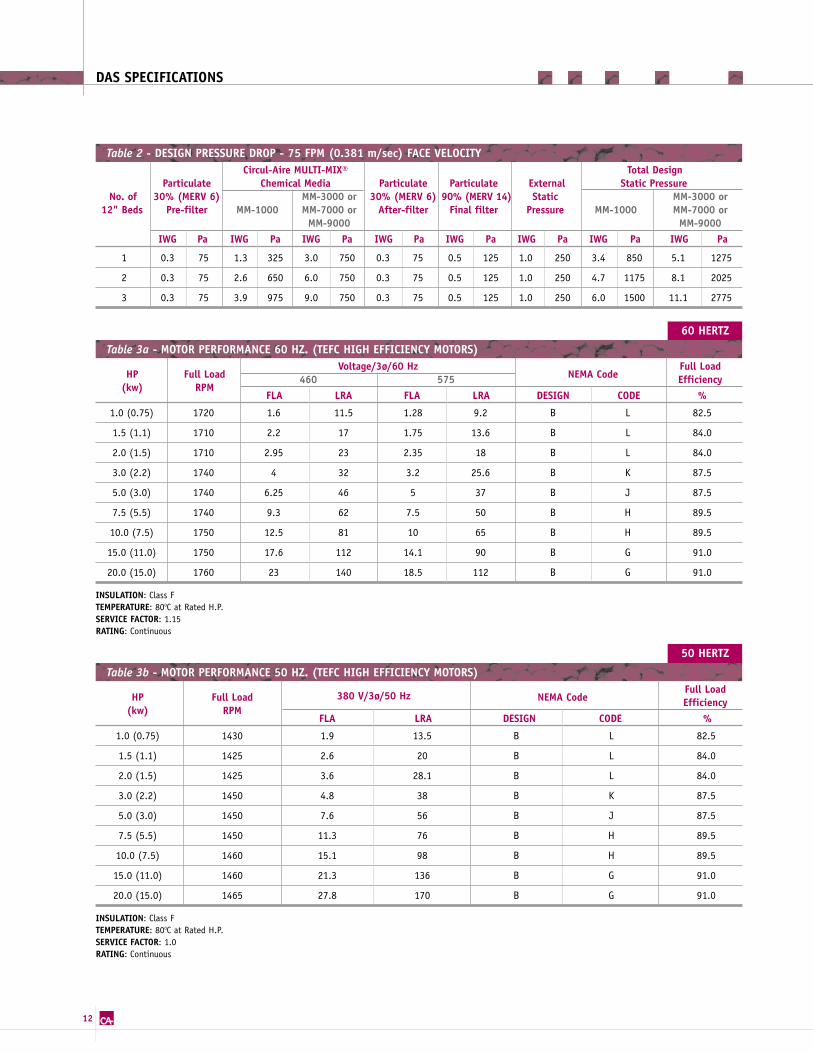
Table 2 - DESIGN PRESSURE DROP - 75 FPM (0.381 m/sec) FACE VELOCITY
HP Full LoadVoltage/3ø/60 Hz
NEMA CodeFull Load
(kw) RPM460 575 Efficiency
FLA LRA FLA LRA DESIGN CODE %
1.0 (0.75) 1720 1.6 11.5 1.28 9.2 B L 82.5
1.5 (1.1) 1710 2.2 17 1.75 13.6 B L 84.0
2.0 (1.5) 1710 2.95 23 2.35 18 B L 84.0
3.0 (2.2) 1740 4 32 3.2 25.6 B K 87.5
5.0 (3.0) 1740 6.25 46 5 37 B J 87.5
7.5 (5.5) 1740 9.3 62 7.5 50 B H 89.5
10.0 (7.5) 1750 12.5 81 10 65 B H 89.5
15.0 (11.0) 1750 17.6 112 14.1 90 B G 91.0
20.0 (15.0) 1760 23 140 18.5 112 B G 91.0
INSULATION: Class FTEMPERATURE: 800C at Rated H.P.SERVICE FACTOR: 1.15RATING: Continuous
Table 3a - MOTOR PERFORMANCE 60 HZ. (TEFC HIGH EFFICIENCY MOTORS)
HP Full Load 380 V/3ø/50 Hz NEMA CodeFull Load
(kw) RPMEfficiency
FLA LRA DESIGN CODE %
1.0 (0.75) 1430 1.9 13.5 B L 82.5
1.5 (1.1) 1425 2.6 20 B L 84.0
2.0 (1.5) 1425 3.6 28.1 B L 84.0
3.0 (2.2) 1450 4.8 38 B K 87.5
5.0 (3.0) 1450 7.6 56 B J 87.5
7.5 (5.5) 1450 11.3 76 B H 89.5
10.0 (7.5) 1460 15.1 98 B H 89.5
15.0 (11.0) 1460 21.3 136 B G 91.0
20.0 (15.0) 1465 27.8 170 B G 91.0
INSULATION: Class FTEMPERATURE: 800C at Rated H.P.SERVICE FACTOR: 1.0RATING: Continuous
Table 3b - MOTOR PERFORMANCE 50 HZ. (TEFC HIGH EFFICIENCY MOTORS)
1 0.3 75 1.3 325 3.0 750 0.3 75 0.5 125 1.0 250 3.4 850 5.1 1275
2 0.3 75 2.6 650 6.0 750 0.3 75 0.5 125 1.0 250 4.7 1175 8.1 2025
3 0.3 75 3.9 975 9.0 750 0.3 75 0.5 125 1.0 250 6.0 1500 11.1 2775

13
DAS SPECIFICATIONS
Table 4 - TYPICAL FAN PERFORMANCE (1-ONLY 12" BED OF MEDIA) 75 FPM (0.381 M/SEC) FACE VELOCITY
ModelsAir Flow
SISW Fan Arrangement Based onMM-1000 at a total ∆P of 3.4 iwg (850 Pa)* MM-3000, 7000 or 9000 at a total ∆P of 5.1 iwg (1275 Pa)*
CFM M3/HR. DIA. (IN.) RPM BHP HP (KW) DIA. (IN.) RPM BHP HP (KW)
* Total ∆p includes 1.0 IWG (250 Pa) external static (as per Table 2).
202 300 510 7.0 2075 0.33 1.0 (0.75) 7.0 2545 0.46 1.0 (0.75)
302 450 765 7.0 2092 0.46 1.0 (0.75) 7.0 2564 0.81 1.0 (0.75)
204 600 1020 7.0 2198 0.69 1.0 (0.75) 7.0 2694 1.04 1.5 (1.1)
304 900 1529 9.0 1695 1.04 1.5 (1.1) 9.0 2008 1.50 2.0 (1.5)
404 1200 2039 13.5 2309 0.92 1.5 (1.1) 13.5 2764 2.07 3.0 (2.2)
504 1500 2549 13.5 2495 1.15 1.5 (1.1) 13.5 2842 1.84 3.0 (2.2)
604 1800 3059 13.5 2466 1.50 2.0 (1.5) 13.5 2807 2.19 3.0 (2.2)
306 1350 2294 13.5 2313 1.04 1.5 (1.1) 13.5 2805 1.96 3.0 (2.2)
406 1800 3059 13.5 2287 1.50 2.0 (1.5) 13.5 2666 2.19 3.0 (2.2)
506 2250 3823 13.5 2482 2.07 3.0 (2.2) 13.5 2815 2.88 5.0 (3.0)
606 2700 4588 15.0 2205 2.42 3.0 (2.2) 15.0 2513 3.34 5.0 (3.0)
706 3150 5352 15.0 2381 3.11 5.0 (3.0) 15.0 2644 4.14 5.0 (3.0)
806 3600 6117 16.5 2100 3.34 5.0 (3.0) 16.5 2353 4.60 5.0 (3.0)
408 2400 4078 15.0 2108 2.07 3.0 (2.2) 15.0 2438 2.99 5.0 (3.0)
508 3000 5098 16.5 1938 2.53 3.0 (2.2) 16.5 2234 3.68 5.0 (3.0)
608 3600 6117 16.5 2100 3.34 5.0 (3.0) 16.5 2353 4.60 7.5 (5.5)
708 4200 7137 18.25 1830 3.80 5.0 (3.0) 18.25 2070 5.18 7.5 (5.5)
808 4800 8156 18.25 1959 4.72 7.5 (5.5) 18.25 2173 6.21 7.5 (5.5)
908 5400 9176 20.0 1926 4.95 7.5 (5.5) 20.0 2115 6.79 7.5 (5.5)
810 6000 10195 20.0 2057 5.98 7.5 (5.5) 20.0 2227 7.82 10.0 (7.5)
910 6750 11470 22.25 1741 6.33 7.5 (5.5) 22.25 1909 8.51 10.0 (7.5)
1010 7500 12744 22.25 1861 7.59 10.0 (7.5) 22.25 2013 9.89 15.0 (11.0)
1011 8250 14018 24.5 1604 7.48 10.0 (7.5) 24.5 1767 10.01 15.0 (11.0)
1012 9000 15293 27.0 1372 7.59 10.0 (7.5) 27.0 1534 10.58 15.0 (11.0)
1212 10800 18351 30.0 1237 9.41 15.0 (11.0) 30.0 1368 12.66 15.0 (11.0)

14
DAS SPECIFICATIONS
202 300 510 7.0 2434 0.46 1.0 (0.75) 7.0 3232 0.805 1.5 (1.1)
302 450 765 7.0 2441 0.69 1.0 (0.75) 7.0 3211 1.15 1.5 (1.1)
204 600 1020 7.0 2504 0.92 1.5 (1.1) 7.0 3253 1.61 2.0 (1.5)
304 900 1529 9.0 1939 1.38 2.0 (1.5) 9.0 2521 2.42 3.0 (2.2)
404 1200 2039 13.5 2685 1.27 1.5 (1.1) 13.5 3576 2.19 3.0 (2.2)
504 1500 2549 13.5 2672 1.61 2.0 (1.5) 13.5 3470 2.88 5.0 (3.0)
604 1800 3059 13.5 2738 1.96 3.0 (2.2) 15.0 3161 3.34 5.0 (3.0)
306 1350 2294 13.5 2677 1.50 2.0 (1.5) 13.5 3512 2.53 3.0 (2.2)
406 1800 3059 13.5 2581 2.07 3.0 (2.2) 15.0 3037 3.45 5.0 (3.0)
506 2250 3823 13.5 2737 2.65 3.0 (2.2) 15.0 3094 4.37 5.0 (3.0)
606 2700 4588 15.0 2442 3.11 5.0 (3.0) 15.0 3057 5.29 7.5 (5.5)
706 3150 5352 15.0 2582 3.80 5.0 (3.0) 15.0 3099 6.21 7.5 (5.5)
806 3600 6117 16.5 2294 4.26 5.0 (3.0) 16.5 2780 7.02 7.5 (5.5)
408 2400 4078 15.0 2365 2.76 5.0 (3.0) 15.0 3050 4.60 7.5 (5.5)
508 3000 5098 16.5 2169 3.45 5.0 (3.0) 16.5 2793 5.87 7.5 (5.5)
608 3600 6117 16.5 2294 4.26 5.0 (3.0) 16.5 2780 7.02 7.5 (5.5)
708 4200 7137 18.25 2015 4.83 7.5 (5.5) 18.25 2504 7.94 10.0 (7.5)
808 4800 8156 18.25 2123 5.87 7.5 (5.5) 18.25 2530 9.09 10.0 (7.5)
908 5400 9176 20.0 2070 6.33 7.5 (5.5) 20.0 2435 10.12 15.0 (11.0)
810 6000 10195 20.0 2188 7.36 10.0 (7.5) 20.0 2527 11.50 15.0 (11.0)
910 6750 11470 22.25 1869 7.94 10.0 (7.5) 22.25 2195 12.65 15.0 (11.0)
1010 7500 12744 22.25 1979 9.32 15.0 (11.0) 22.25 2280 14.38 20.0 (15.0)
1011 8250 14018 24.5 1728 9.32 15.0 (11.0) 24.5 2032 14.95 20.0 (15.0)
1012 9000 15293 27.0 1497 9.89 15.0 (11.0) 27.0 1776 15.98 20.0 (15.0)
1212 10800 18351 30.0 1368 12.66 15.0 (11.0) 30.0 1587 19.33 25.0 (18.5)
Table 5 - TYPICAL FAN PERFORMANCE (2-ONLY 12" BEDS OF MEDIA) 75 FPM (0.381 M/SEC) FACE VELOCITY
ModelsAir Flow
SISW Fan Arrangement Based onMM-1000 at a total ∆P of 4.7 iwg (1175 Pa)* MM-3000, 7000 or 9000 at a total ∆P of 8.1 iwg (2025 Pa)*
CFM M3/HR. DIA. (IN.) RPM BHP HP (KW) DIA. (IN.) RPM BHP HP (KW)
*Total ∆P includes 1.0 IWG (250 Pa) external static (as per Table 2).

15
DAS SPECIFICATIONS
Table 6 - TYPICAL FAN PERFORMANCE (3-ONLY 12" BEDS OF MEDIA) 75 FPM (0.381 M/SEC) FACE VELOCITY
ModelsAir Flow
SISW Fan Arrangement Based onMM-1000 at a total ∆P of 6.0 iwg (1500 Pa)* MM-3000, 7000 or 9000 at a total ∆P of 11.1 iwg (2775 Pa)*
CFM M3/HR. DIA. (IN.) RPM BHP HP (KW) DIA. (IN.) RPM BHP HP (KW)
*Total ∆P includes 1.0 IWG (250 Pa) external static (as per Table 2).
CF = Consult Factory
202 300 510 7.0 2763 0.58 1.0 (0.75) CF CF CF CF
302 450 765 7.0 2753 0.92 1.5 (1.1) 9.0 2890 1.61 2.0 (1.5)
204 600 1020 7.0 2818 1.15 1.5 (1.1) 9.0 2982 2.19 3.0 (2.2)
304 900 1529 9.0 2157 1.84 3.0 (2.2) 9.0 2995 3.34 5.0 (3.0)
404 1200 2039 13.5 2990 1.73 3.0 (2.2) 9.0 3166 4.37 5.0 (3.0)
504 1500 2549 13.5 3008 2.07 3.0 (2.2) 11.0 2381 4.95 7.5 (5.5)
604 1800 3059 13.5 3072 2.53 3.0 (2.2) 16.5 3369 4.60 7.5 (5.5)
306 1350 2294 13.5 3027 1.84 3.0 (2.2) 11.0 2388 4.86 7.5 (5.5)
406 1800 3059 13.5 2931 2.65 3.0 (2.2) 13.0 2021 5.98 7.5 (5.5)
506 2250 3823 13.5 2986 3.34 5.0 (3.0) 15.0 1752 7.50 10.0 (7.5)
606 2700 4588 15.0 2667 3.91 5.0 (3.0) 16.5 3271 7.13 10.0 (7.5)
706 3150 5352 15.0 2784 4.72 7.5 (5.5) 16.5 3278 8.28 10.0 (7.5)
806 3600 6117 16.5 2487 5.29 7.5 (5.5) 15.0 1752 12.08 15.0 (11.0)
408 2400 4078 15.0 2654 3.45 5.0 (3.0) 13.0 2046 8.05 10.0 (7.5)
508 3000 5098 16.5 2378 4.37 5.0 (3.0) 15.0 1757 10.01 15.0 (11.0)
608 3600 6117 16.5 2487 5.29 7.5 (5.5) 15.0 1774 12.08 15.0 (11.0)
708 4200 7137 18.25 2189 5.98 7.5 (5.5) 17.0 1557 13.11 15.0 (11.0)
808 4800 8156 18.25 2283 7.02 7.5 (5.5) 17.0 1562 15.07 20.0 (15.0)
908 5400 9176 20.0 2216 7.71 10.0 (7.5) 20.0 2842 13.69 15.0 (11.0)
810 6000 10195 20.0 2318 8.86 10.0 (7.5) 20.0 2842 15.23 20.0 (15.0)
910 6750 11470 22.25 2000 9.66 15.0 (11.0) 22.25 2562 17.14 20.0 (15.0)
1010 7500 12744 22.25 2093 11.16 15.0 (11.0) 22.25 2522 19.09 25.0 (18.5)
1011 8250 14018 24.5 1852 11.50 15.0 (11.0) 24.5 2287 19.55 25.0 (18.5)
1012 9000 15293 27.0 1613 12.19 15.0 (11.0) 27.0 2076 22.77 30.0 (22.0)
1212 10800 18351 30.0 1447 14.88 20.0 (15.0) 30.0 1812 24.77 30.0 (22.0)

16
DAS DIMENSIONS
202 300 510 34 864 26 660 CF CF CF CF CF CF
302 450 765 46 1168 26 660 CF CF CF CF CF CF
204 600 1020 34 864 50 1270 CF CF CF CF CF CF
304 900 1529 46 1168 50 1270 104 2642 87 2210 1750 795
404 1200 2039 58 1473 50 1270 106 2692 88 2235 2070 940
504 1500 2549 70 1778 50 1270 110 2794 89 2261 2300 1044
604 1800 3059 82 2083 50 1270 113 2870 89 2261 2500 1135
306 1350 2294 46 1168 74 1880 111 2819 89 2261 2350 1067
406 1800 3059 58 1473 74 1880 113 2870 89 2261 2620 1190
506 2250 3823 70 1778 74 1880 116 2946 90 2286 2900 1317
606 2700 4588 84 2134 74 1880 119 3023 90 2286 3300 1498
706 3150 5352 96 2438 74 1880 133 3378 101 2565 3750 1703
806 3600 6117 108 2743 74 1880 136 3454 101 2565 4150 1884
408 2400 4078 60 1524 98 2489 120 3048 89 2261 3350 1521
508 3000 5098 72 1829 98 2489 126 3200 90 2286 3870 1760
608 3600 6117 84 2134 98 2489 136 3454 101 2565 4290 1948
708 4200 7137 96 2438 98 2489 137 3480 101 2565 4650 2111
808 4800 8156 108 2743 98 2489 137 3480 101 2565 4940 2243
908 5400 9176 122 3099 98 2489 139 3531 103 2616 5400 2452
810 6000 10195 110 2794 122 3099 140 3556 104 2642 5940 2697
910 6750 11470 122 3099 122 3099 140 3556 104 2642 6280 2851
1010 7500 12744 134 3404 122 3099 142 3607 106 2692 6820 3096
1011 8250 14018 134 3404 134 3404 142 3607 106 2692 7180 3260
1012 9000 15293 134 3404 146 3708 142 3607 106 2692 7580 3441
1212 10800 18351 158 4013 146 3708 149 3785 113 2870 8350 3791
Table 7 - PLUG BLOWER TYPE - DRAW-THROUGH & BLOW-THROUGH ARRANGEMENTS
Models Air FlowOverall Width Length* (for single 12" bed)
Height (H) (W) Draw-through Blow-through Weight** CFM M3/HR. INCHES MM INCHES MM INCHES MM INCHES MM LB. KG.
* Add 12" (305 mm) in length per additional bed; maximum 3 beds total. CF Consult Factory
** MEDIA NOT INCLUDED See bottom of Table 1 for media weights.Weights based on zinc coated steel and stainless steel construction. See below for aluminum construction weights.
ALUMINUM CONSTRUCTION WEIGHT: Multiply zinc coated steel weight in table by 0.65.
Example: DAS-406, zinc coated steel weight from table is 2620 lb. - 2620 lb. x 0.65 = 1703 lb. aluminum construction.
All weights are approximate and may vary depending on final construction. Actual weights can be provided upon request.

17
DAS DIMENSIONS
202 300 510 34 864 26 660 CF CF CF CF CF CF
302 450 765 46 1168 26 660 CF CF CF CF CF CF
204 600 1020 34 864 50 1270 CF CF CF CF CF CF
304 900 1529 46 1168 50 1270 104 2642 100 2540 1750 795
404 1200 2039 58 1473 50 1270 106 2692 106 2692 2070 940
504 1500 2549 70 1778 50 1270 110 2794 112 2845 2300 1044
604 1800 3059 82 2083 50 1270 113 2870 114 2896 2500 1135
306 1350 2294 46 1168 74 1880 111 2819 112 2845 2350 1067
406 1800 3059 58 1473 74 1880 113 2870 114 2896 2620 1190
506 2250 3823 70 1778 74 1880 116 2946 116 2946 2900 1317
606 2700 4588 84 2134 74 1880 119 3023 121 3073 3300 1498
706 3150 5352 96 2438 74 1880 133 3378 124 3150 3750 1703
806 3600 6117 108 2743 74 1880 136 3454 130 3302 4150 1884
408 2400 4078 60 1524 98 2489 120 3048 125 3175 3350 1521
508 3000 5098 72 1829 98 2489 126 3200 130 3302 3870 1760
608 3600 6117 84 2134 98 2489 136 3454 130 3302 4290 1948
708 4200 7137 96 2438 98 2489 137 3480 130 3302 4650 2111
808 4800 8156 108 2743 98 2489 137 3480 132 3353 4940 2243
908 5400 9176 122 3099 98 2489 139 3531 134 3404 5400 2452
810 6000 10195 110 2794 122 3099 140 3556 134 3404 5940 2697
910 6750 11470 122 3099 122 3099 140 3556 142 3607 6280 2851
1010 7500 12744 134 3404 122 3099 142 3607 142 3607 6820 3096
1011 8250 14018 134 3404 134 3404 142 3607 146 3708 7180 3260
1012 9000 15293 134 3404 146 3708 142 3607 150 3810 7580 3441
1212 10800 18351 158 4013 146 3708 149 3785 154 3912 8350 3791
Table 8 - SISW - COMPLETE FAN ASSEMBLY - DRAW-THROUGH & BLOW-THROUGH ARRANGEMENTS
Models Air FlowOverall Width Length* (for single 12" bed)
Height (H) (W) Draw-through Blow-through Weight** CFM M3/HR. INCHES MM INCHES MM INCHES MM INCHES MM LB. KG.
* Add 12" (305 mm) in length per additional bed; maximum 3 beds total. CF Consult Factory
** MEDIA NOT INCLUDED See bottom of Table 1 for media weights.Weights based on zinc coated steel and stainless steel construction. See below for aluminum construction weights.
ALUMINUM CONSTRUCTION WEIGHT: Multiply zinc coated steel weight in table by 0.65.
Example: DAS-406, zinc coated steel weight from table is 2620 lb. - 2620 lb. x 0.65 = 1703 lb. aluminum construction.
All weights are approximate and may vary depending on final construction. Actual weights can be provided upon request.

18
DAS - PLUG BLOWER ASSEMBLY - DRAW-THROUGH ARRANGEMENT
W
L
MEDIA
LOADING
DOOR
MEDIA
LOADING
DOOR
MEDIA
LOADING
DOOR
AIR FLOWAIR FLOW
Access provided on both sides for systems wider than 6 feet
ACCESS
DOOR
B
(3X) MEDIA DISCHARGE GATE
MEDIA
FILLING
AIR FLOW AIR FLOW
MEDIA
FILLING
MEDIA
FILLING
H
Plan View
Elevation View

19
DAS - PLUG BLOWER ASSEMBLY - BLOW-THROUGH ARRANGEMENT
L
MEDIA
LOADING
DOOR
MEDIA
LOADING
DOOR
MEDIA
LOADING
DOOR
AIR FLOW
AIR FLOW
AIR FLOW
W
Access provided on both sides for systems wider than 6 feet
H
B
MEDIA
FILLING
MEDIA
FILLING
MEDIA
FILLING
AIR FLOW AIR FLOW
ACCESS
DOOR
(3X) MEDIA DISCHARGE GATE
Plan View
Elevation View

20
L
MEDIA
LOADING
DOOR
AIR FLOW
MEDIA
LOADING
DOOR
MEDIA
LOADING
DOOR
AIR FLOW
W
Access provided on both sides for systems wider than 6 feet
H
B
MEDIA
FILLING
(3X) MEDIA DISCHARGE GATE
AIR FLOW
MEDIA
FILLING
MEDIA
FILLING
AIR FLOW
ACCESS
DOOR
DAS - PLUG BLOWER ASSEMBLY - BLOW-THROUGH ARRANGEMENT
Plan View
Elevation View

21
L
MEDIA
LOADING
DOOR
AIR FLOW
AIR FLOW
MEDIA
LOADING
DOOR
MEDIA
LOADING
DOOR
W
Access provided on both sides for systems wider than 6 feet
H
B
MEDIA
FILLING
(3X) MEDIA DISCHARGE GATE
MEDIA
FILLING
MEDIA
FILLING
AIR FLOW
DAS - SISW FAN ASSEMBLY - BLOW-THROUGH ARRANGEMENT
Plan View
Elevation View

22
L
MEDIA
LOADING
DOORAIR FLOW
MEDIA
LOADING
DOOR
MEDIA
LOADING
DOOR
W
Access provided on both sides for systems wider than 6 feet
H
B
MEDIA
FILLING
(3X) MEDIA DISCHARGE GATE
MEDIA
FILLING
MEDIA
FILLING
AIR FLOW
AIR FLOW
DAS - SISW FAN ASSEMBLY - DRAW-THROUGH ARRANGEMENT
Plan View
Elevation View

23
MULTI-MIX® MEDIA & TECH-CHEKTM SERVICE
Circul-Aire's MULTI-MIX® is a proven
filter media which provides continuous
purification of corrosive, odorous and
toxic contaminants in industrial and
commercial environments. MULTI-MIX®
media combines the adsorption
properties of activated carbon with
the oxidation properties of chemically
enhanced alumina. For more informa-
tion on MULTI-MIX® media, refer to
our MULTI-MIX® brochures.
Media analysis through our lifetime
TECH-CHEKTM Program ensures maximum
efficiency of our products. A complete
computerized report establishes media
replacement schedule for each unit.
Circul-Aire's laboratory can also
provide additional performance tests
for specific air contaminants.
REACTIVITY MONITORING SERVICE (REMO) & SURVEYOR®
Circul-Aire's Reactivity Monitoring
Service (REMO) diagnoses according
to the ISA the corrosion level from
mild to severe (G1 to GX). Severity
level is gauged by means of reactivity
monitoring coupons which are installed
in strategic areas for periods of
30 to 90 days.
These REMO coupons contain specially
treated copper and silver strips that
react with the environment. After
exposure, coupons are analyzed
to determine film thickness and
chemistry: data are further used to
determine MULTI-MIX® media selection
and then normalized to a one-month
value for ISA classification. The silver
coupon can also be analyzed to
evaluate the presence of chlorine
and probable humidity level.
The SURVEYOR® on-line environmen-
tal monitoring provides the operator
with real-time evaluation of the
room's environment as per the
Instrument Society of America (ISA)
classification for applications where
instantaneous readings are required.
SEALING INTEGRITY VERIFICATION (SIV)
The Sealing Integrity Verification
(SIV) measures the protected area
where process control equipment
is located. Building enclosures can
never be perfectly sealed. Often
leakage allows contaminated air
to infiltrate usually in significant
quantities, even to the extent of
preventing the required pressurization.
The Sealing Integrity Verification
(SIV) measures room differential
pressure and flow pressure of pressur-
ization/depressurization. The values
are used to calculate probable effective
leakage area and geometry. Should
verification analysis prove improper
sealing, leakage identification and
sealing procedures are implemented.
MULTI-MIX® MEDIA & SERVICES

OTHER CIRCUL-AIRE PRODUCTS
AIR PURIFICATION SYSTEMS
LIT
0020
0-CA
0804
-2K
Prin
ted
in C
anad
a.
10935 Crabapple Road, Suite 202-A, Roswell, Georgia 30075 USA3999 Cote Vertu, Montreal, Quebec, Canada H4R 1R2Tel.: 514.336.3330 Fax: 514.337.33361.800.800.1868
www.circul-aire.comCircul-Aire Inc. is a subsidiary of Dectron Internationale
Circul-Aire Inc. reserves the right to make any changes in the design or specifications of any product at any time without notice.
designer indoor air®