deep groundwater conditions report - westlands...
TRANSCRIPT

Deep Groundwater
Conditions Report
December 2015
Westlands Water District April 2016

1
Introduction
Westlands Water District (District) located on the west side of the San Joaquin Valley in
Fresno and Kings Counties. The District receives water for irrigation from surface sources
delivered through the Delta-Mendota Canal and the San Luis Canal (SLC) and from
groundwater.
Agricultural production in the District area was originally developed and sustained with
groundwater for irrigation. Surface water deliveries from the San Luis Unit of the Central Valley
Project (CVP) began in 1968 with the goal to reduce historical groundwater pumping. However,
the District’s contractual entitlements for CVP water are not sufficient to supply the agricultural
demands of the District, thus some groundwater pumping is still required. Since 1990, CVP
water supplies have been due to drought and regulatory actions resulting from the Central Valley
Project Improvement Act (CVPIA), the Endangered Species Act (ESA), Bay/Delta water quality
requirements and Court orders. As a result, groundwater pumping has increased to meet crop
water demands.
This increased reliance on groundwater resources to supplement surface water resulted in
the development of the District’s Groundwater Management Plan in 1996, which includes
continuation of this groundwater monitoring and reporting program.

2
Geology
The San Joaquin Valley is a wide bedrock basin filled with thousands of feet of alluvial
sediment deposited by streams and rivers flowing out of the adjacent mountains on both the east
and the west. Westlands is located near the centerline of this basin, bordered on the east by the
Fresno Slough and on the west by the Diablo Range of the California Coast Ranges.
The Diablo Range consists of complex, folded, and uplifted mountains, which are
composed predominantly of sandstone and shale of marine origin. Eroded by creeks flowing
from the Diablo Range, sediments form gentle sloping alluvial fans. The texture of the Diablo
Range deposits depends on the relative position on the alluvial fan and ranges from coarse sand
and gravel to fine silt and clay. Generally, those portions of Westlands lying high on the alluvial
fans have permeable, medium-textured soils. With decreasing elevation from the west to east,
soil textures become finer. These fine textured soils are characterized by low permeability and
increased concentrations of water-soluble solids, primarily salts and trace elements.
The Sierra Nevada on the east side of the Valley is predominately comprised of uplifted
granite rock overlaid in areas by sedimentary and metamorphic rock. Sierran alluvial deposits in
the District consist primarily of well-sorted sands, with minor amounts of clay. The Sierran
alluvium decreases in thickness and increases in depth below the surface toward the west. These
coarse-textured sediments are characterized by high permeability and a low concentration of
water-soluble solids.
One of the principal subsurface geological features of the San Joaquin Valley is the
Corcoran Clay formation. Formed as a lakebed about 600,000 years ago, this clay layer ranges
in thickness from 20 to 200 feet and underlies most of the District. Varying depths from 200 to
500 feet in the Valley through to 850 feet along the Diablo Range, the Corcoran Clay divides the
groundwater system into two major aquifers—a confined aquifer below and a semi-confined
system above.
Westside Groundwater Basin
The groundwater basin underlying the District is comprised generally of two water-
bearing zones: (1) an upper zone above a nearly impervious Corcoran Clay layer containing the
Coastal and Sierran aquifers and (2) a lower zone below the Corcoran Clay containing the Sub-
Corcoran aquifer. These water-bearing zones are recharged by subsurface inflow from the west,
east, and northeast, and by percolation of applied surface water. A generalized cross section of

3
the District showing the Corcoran Clay and these water-bearing zones is shown in Figure 1.
The Corcoran Clay separates the upper and lower water bearing zones in the majority of
the District; however, it is not continuous and diminishes near the San Luis Canal. The United
States Geological Survey (USGS) lines of equal elevation for the base of the Corcoran Clay are
shown in Figure 2.
Groundwater quality, measured as electrical conductivity, in the lower water-bearing
zone (Sub-Corcoran aquifer) varies throughout the District as shown in Figure 3. Typically,
water quality varies with depth, with poorer quality present at the upper and lower limits of the
aquifer and with the optimum quality somewhere between. The upper limit of the lower aquifer
is the base of the Corcoran Clay and the USGS identifies the lower limit as the base of the fresh
groundwater. The quality of the groundwater below the base of fresh water exceeds 2,000 parts
per million total dissolved solids (TDS) which is too high for irrigating crops. The elevation for
the base of the fresh groundwater is shown in Figure 4.
Figure 1: A generalized Hydro-geological Cross Section of the District.

4 Figure 2: Elevation of the Base of the Corcoran Clay (USGS Lines of Equal Elevation)
Fre
sno
Cou
nty
Kin
gs C
oun
ty
Biola
Huron
Kerman
Fresno
Mendota
Coalinga
Caruthers
Riverdale
Firebaugh
Raisin CitySan Joaquin
Cantua Creek
Tranquillity
Five Points
California A
queduct
San Luis D
rain
Avenal
Lemoore
Kettleman City
Stratford
600
700
650
550
500
750
450
800
850
400
350
300
700
700
750
750
650
850
600
600
75070
0
500
800
800
700
600
500
800
700
750 550
850 600
550
850
550
650
65065
0
650
700
450
550
800
650
650
600
700
800
650
650
650
750
700
750
Source: USGS Central Valley Hydrologic Model (CVHM)
C:\W
WD
_Dat
a\20
16-W
-001
9\F
igur
e 2
Cor
cora
n C
lay
Ext
ent a
nd D
epth
.mxd
Data Source: Central Valley Hydrologic ModelGround Surface Elevation Datums: Horizontal Datum of NAD83 and Vertical Datum of NAVD 88Date: 4/7/2016
WESTLANDS WATER DISTRICTWESTLANDS WATER DISTRICTWESTLANDS WATER DISTRICTWESTLANDS WATER DISTRICT
3130 N. FRESNO ST.FRESNO, CALIFORNIA 93703
559.224.1523 FAX 559.241.6277
Figure 2Corcoran Clay Characteristics:
Extent and Depth
Legend
Highways\Major Roads
Waterway
County Boundary
Westlands WaterDistrict Boundary
Extent of Corcoran Clay
Depth to Top of Corcoran Clay (Feet)(Relative to Ground Elevation)
870'
540'
215'
0 3 6Miles
Date: 4/7/2016

5 Figure 3: The Sub-Corcoran Groundwater, Electrical Conductivity (dS/m), December 2015.
Fres
no C
ount
yK
ings
Cou
nty
Biola
Huron
Kerman
Fresno
Mendota
Coalinga
Caruthers
Riverdale
Firebaugh
Raisin CitySan Joaquin
Cantua Creek
Tranquillity
Five Points
California A
queduct
San Luis D
rain
Avenal
Lemoore
Kettleman City
Stratford
Source: USGS Central Valley Hydrologic Model (CVHM)
C:\W
WD
_Dat
a\20
16-W
-001
9\F
igur
e 3
Ele
ctric
al C
ond
uctiv
ity 2
015.
mxd
Ground Surface Elevation Datums: Horizontal Datum of NAD83 and Vertical Datum of NAVD 88
WESTLANDS WATER DISTRICTWESTLANDS WATER DISTRICTWESTLANDS WATER DISTRICTWESTLANDS WATER DISTRICT
3130 N. FRESNO ST.FRESNO, CALIFORNIA 93703
559.224.1523 FAX 559.241.6277
Figure 3Sub-Corcoran Groundwater,
Electrical Conductivity (dS/m)December 2015
Legend
Highways\Major Roads
Waterway
County Boundary
Westlands Water District Boundary
Electrical Conductivity (dS/m)
< 2.0
2. 0 - 4.0
> 4. 00 3 6
Miles
Date: 4/7/2016

6 Figure 4: The elevation of the Base of Fresh Groundwater (USGS Lines of Equal Elevation).
Fre
sno
Cou
nty
Kin
gs C
oun
ty
Biola
Huron
Kerman
Fresno
Mendota
Coalinga
Caruthers
Riverdale
Firebaugh
Raisin CitySan Joaquin
Cantua Creek
Tranquillity
Five Points
California A
queduct
San Luis D
rain
Avenal
Lemoore
Kettleman City
Stratford
-1800
-1600
-1400
-1200
-1000
-800
-2000
-600
-220
0
-2400
-2600
-1400
-2400
-24
00
-1400
-1800
-1400
-600
-2200
-800
-600
-1800
-120
0
-1000
-2000
-1600
-1200
-2000-1800
-1600
-600
-2200
Source: USGS Central Valley Hydrologic Model (CVHM)
C:\W
WD
_Dat
a\20
16-W
-001
9\F
igur
e 4
Ele
vatio
n of
the
Bas
e of
Fre
sh G
roun
dwat
er.m
xd
Vertical Datum of Mean Sea Level (MSL)
WESTLANDS WATER DISTRICTWESTLANDS WATER DISTRICTWESTLANDS WATER DISTRICTWESTLANDS WATER DISTRICT
3130 N. FRESNO ST.FRESNO, CALIFORNIA 93703
559.224.1523 FAX 559.241.6277
Figure 4Elevation of the Base of
Fresh Groundwater
Legend
Highways\Major Roads
Waterway
County Boundary
Westlands Water District Boundary
Elevation of the Baseof Fresh Groundwater(Mean Sea Level)
- 400'
- 1,600'
- 2,850'
0 3 6Miles
Date: 4/7/2016

7
Groundwater Monitoring Program
CVP Project water and other surface water supplies are carefully allocated and all
deliveries are metered, resulting in accurate water use data to manage the supplies and determine
water delivery costs. Surface water quality is monitored by state and federal agencies.
Groundwater measurements and quality testing have proved useful to water users in
helping them manage water supplies, facilitate accurate irrigation-scheduling, monitor pump
efficiency and participate in District groundwater programs. It also enables the District to better
monitor groundwater supplies, calculate drought impacts, and determine long-term water needs.
Groundwater monitoring is an essential part of managing any conjunctive use program.
This information is vital to determine the effect of groundwater pumping on the aquifer, aquifer
water quality, pumping costs, and subsidence. Without effective monitoring, the short and long-
term impacts of conjunctive use cannot be determined.
Annually, District wells are monitored by sounding each well while in a static condition
for depth or by measuring the electrical conductivity of the water while the pump is operating.
Results from the annual survey are stored in a groundwater database and used to formulate
District reports and maps. The survey information enables the District to monitor groundwater
trends, provide reports to water users, estimate District-wide pumped groundwater quantities,
and calculate seasonal application efficiency more accurately.
Many of the District water users participated in the Canal Integration Program (CIP) and
the Groundwater Distribution Integration Program (DIP) from 1990-1994, which allowed
groundwater to be pumped into the SLC and into the District’s distribution system. The water
users received surface water credits for the volume of groundwater pumped into the system,
which was then used to meet their crop demand schedule. However, in 1995, the California
Department of Water Resources (DWR) suspended the discharge of groundwater into the SLC,
due to concerns that groundwater could degrade the water quality. The DIP program has
continued throughout this period except in years when the District received 100 percent
allocation. Briefly, in 2008, DWR allowed the District to pump groundwater into the SLC for
the period June through September because of restricted pumping from the Delta. In 2014, the
District was again allowed to pump groundwater into the SLC for the period July through
November and a small amount in February 2015. CIP pumping was again allowed from August
to October 2015.
District staff conducted the Annual Deep Groundwater Survey for 2015 and visited 1,210

8
well locations. The total number of operational wells within the District was 792 of which
97.1% have meters and 124 non-operational wells of which 56.5% have meters. Additionally,
the District visited 32 wells outside its boundaries finding 25 operational wells of which 68.0%
have meters and 7 non-operational wells with one having a meter. The majority of the non-
District wells monitored are located along the District’s eastern boundary.
The reduction of CVP water and other surface water supplies has resulted in the
construction of many new wells. There have been 605 new wells constructed within the District
since 2000, to make up for the shortfall in surface irrigation water.

9
Historic Conditions
Prior to the delivery of CVP water into the District, the annual groundwater pumping
ranged from 800,000 to 1,000,000 acre-feet (AF) during the period of 1950-1968. The majority
of this pumping was from the aquifer below the Corcoran Clay causing the sub-Corcoran
piezometric groundwater surface (groundwater surface) to reach the lowest recorded average
elevation of 156 feet below mean sea level in 1967. The USGS concluded that extraction of
large quantities of groundwater prior to CVP deliveries resulted in compaction of water bearing
sediments and caused land subsidence ranging from 1 to 24 feet between 1926 and 1972 (U.S.
Geological Survey, 1988).
After CVP water deliveries began in 1968, the groundwater surface rose steadily until
reaching 89 feet above mean sea level in 1987, the highest average elevation on record dating
back to the early 1940’s. The only exception during this period was in 1977 when a drought and
drastic reduction of CVP deliveries resulted in groundwater pumping of approximately 472,000
AF and an accompanying drop in the groundwater surface elevation of approximately 97 feet.
During the early 1990’s, groundwater pumping increased due to reduced CVP water
supplies due to drought, regulatory actions related to the Central Valley Project Improvement
Act, the Endangered Species Act, and Bay/Delta water quality requirements. Groundwater
pumping reached an estimated 600,000 AF annually during 1991 and 1992 when the District
received only 25 percent of its contractual entitlement of CVP water. This increased pumping
caused the groundwater surface to decline to 62 feet below mean sea level, the lowest elevation
since 1977. The Department of Water Resources estimated the amount of subsidence since 1983
to be almost two feet in some areas of the District, with most of that subsidence occurring since
1989.
Recent Conditions
Over the last five years, 2011 to 2015, CVP allocations averaged 28% (319,693 acre-
feet), total groundwater pumped was 2,353,000 acre-feet and the groundwater surface elevation
decreased 169 feet. The CVP allocation for the 2015/16 water year was 0% (0 acre-feet) and
with the accompanying increase in groundwater pumped (660,000 acre-feet), the groundwater
surface decreased 44 feet from 2014/15 to 2015/16 to an average elevation of 120 feet below
mean sea level. With the 2016/17 water year CVP allocation again at 0%, the District anticipates
groundwater pumping will range from 650,000 – 700,000 AF. The water elevation could drop

10
between 20 and 50 feet to levels not seen since the 1960’s.
Groundwater elevations and the estimated amount of groundwater pumped for the last
sixty years are shown in Table 2. This table shows the average elevation of the groundwater in
the lower water bearing zone and the change in elevation for each year.
Crop1 Year
Pumped
AF
Elevation
FT
Elevation Change
FT
Crop Year
Pumped
AF
Elevation
FT
Elevation Change
FT
1956 964,000 -65 -13 1986 145,000 71 8 1957 928,000 -56 9 1987 159,000 89 18 1958 884,000 -29 27 1988 160,000 64 -25 1959 912,000 -77 -48 1989 175,000 63 -1 1960 872,000 -81 -4 1990 300,000 9 -54 1961 824,000 -96 -15 1991 600,000 -32 -41 1962 920,000 1992 600,000 -62 -30 1963 883,000 1993 225,000 1 63 1964 913,000 1994 325,000 -51 -52 1965 822,000 1995 150,000 27 78 1966 924,000 -134 1996 50,000 49 22 1967 875,000 -156 -22 1997 30,000 63 14 1968 596,000 -135 21 1998 15,000 63 0 1969 592,000 -120 15 1999 20,000 65 2 1970 460,000 -100 20 2000 225,000 43 -22 1971 377,000 -93 7 2001 215,000 25 -18 1972 -54 39 2002 205,000 22 -3 1973 -37 17 2003 160,000 30 8 1974 96,000 -22 15 2004 210,000 24 -6 1975 111,000 -11 11 2005 75,000 56 32 1976 97,000 -2 9 2006 15,000 77 21 1977 472,000 -99 -97 2007 310,000 35 -42 1978 159,000 -4 95 2008 460,000 -11 -46 1979 140,000 -13 -9 2009 480,000 -31 -20 1980 106,000 4 17 2010 140,000 9 40 1981 99,000 11 7 2011 45,000 49 40 1982 105,000 32 21 20122 355,000 1 -48 1983 31,000 56 24 2013 638,000 -58 -59 1984 73,000 61 5 2014 655,000 -76 -18 1985 228,000 63 2 2015 660,000 -120 -44
Table 2: 60-years of estimated groundwater pumpage.3
1 Crop year is from 1 October (previous year) to 30 September (current year) for the year in question. 2 Starting with 2012 the amount of groundwater pumped is for Water Year (March 1 through February 28). 3 Data compiled from PG&E power records by USBR through 1971 and USGS 1974-1987, District estimates 1988-present. Elevation data for 1943-1961 and 1977 from Bill Coor, USBR (requested by the District and received on 4/20/1978) and elevation for 1966-1976 from Plate 5 of “Project Effects on Sub-Corcoran Water Layers” (April 1977).

11
Figure 5 shows in graphical format the historical average elevation of the Sub-Corcoran
piezometric groundwater surface and the estimated amount of groundwater pumped in the
District for the last 30 years. Figures 6 and 7 shows the depth to the piezometric groundwater
surface in the lower water-bearing zone during December 2011 and during December 2015,
respectively. Change in depth to the piezometric groundwater surface from December 2011 to
December 2015 is shown in Figure 8.
In addition to monitoring the water levels of wells pumping from the lower aquifer, the
wells pumping from the upper aquifer are also monitored. The majority of the wells pumping
from the upper aquifer had groundwater surface levels 100 to 300 feet below ground surface
during December 2015 as shown in Figure 9.
Figure 5: The Historical Average Elevation of Sub-Corcoran Piezometric Groundwater Surface and Groundwater
Pumpage.

12 Figure 6: Depth to Sub-Corcoran Piezometric Groundwater Surface, December 2011.
Fre
sno
Cou
nty
Kin
gs C
oun
ty
Biola
Huron
Kerman
Fresno
Mendota
Coalinga
Caruthers
Riverdale
Firebaugh
Raisin CitySan Joaquin
Cantua Creek
Tranquillity
Five Points
California A
queduct
San Luis D
rain
Avenal
Lemoore
Kettleman City
Stratford
Source: USGS Central Valley Hydrologic Model (CVHM)
C:\W
WD
_Dat
a\20
16-W
-001
9\F
igur
e 6
Dep
th to
Sub
-Cor
cora
n D
ec 2
011
WW
D.m
xd
Ground Surface Elevation Datums: Horizontal Datum of NAD83 and Vertical Datum of NGVD 29
WESTLANDS WATER DISTRICTWESTLANDS WATER DISTRICTWESTLANDS WATER DISTRICTWESTLANDS WATER DISTRICT
3130 N. FRESNO ST.FRESNO, CALIFORNIA 93703
559.224.1523 FAX 559.241.6277
Figure 6Depth to Sub-Corcoran
Piezometric Groundwater SurfaceDecember 2011
Legend
Highways\Major Roads
Waterway
County Boundary
Westlands WaterDistrict Boundary
Depth to Groundwater
(Relative to Ground Elevation)
0 - 200'
200' - 400'
400' - 600
600' - 800'
0 3 6Miles
Date: 4/7/2016
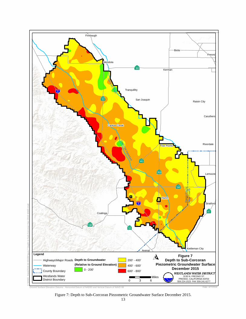
13 Figure 7: Depth to Sub-Corcoran Piezometric Groundwater Surface December 2015.
Fre
sno
Cou
nty
Kin
gs C
oun
ty
Biola
Huron
Kerman
Fresno
Mendota
Coalinga
Caruthers
Riverdale
Firebaugh
Raisin CitySan Joaquin
Cantua Creek
Tranquillity
Five Points
California A
queduct
San Luis D
rain
Avenal
Lemoore
Kettleman City
Stratford
Source: USGS Central Valley Hydrologic Model (CVHM)
C:\W
WD
_Dat
a\20
16-W
-001
9\F
igur
e 7
Dep
th to
Sub
-Cor
cora
n D
ec 2
015
WW
D.m
xd
Ground Surface Elevation Datums: Horizontal Datum of NAD83 and Vertical Datum of NAVD 88
WESTLANDS WATER DISTRICTWESTLANDS WATER DISTRICTWESTLANDS WATER DISTRICTWESTLANDS WATER DISTRICT
3130 N. FRESNO ST.FRESNO, CALIFORNIA 93703
559.224.1523 FAX 559.241.6277
Figure 7Depth to Sub-Corcoran
Piezometric Groundwater SurfaceDecember 2015
Legend
Highways\Major Roads
Waterway
County Boundary
Westlands WaterDistrict Boundary
Depth to Groundwater
(Relative to Ground Elevation)
0 - 200'
200' - 400'
400' - 600'
600' - 800'
0 3 6Miles
Date: 4/7/2016

14 Figure 8: Change in Depth to the Sub-Corcoran Piezometric Groundwater Surface 2011-2015.
Fre
sno
Cou
nty
Kin
gs C
oun
ty
Biola
Huron
Kerman
Fresno
Mendota
Coalinga
Caruthers
Riverdale
Firebaugh
Raisin CitySan Joaquin
Cantua Creek
Tranquillity
Five Points
California A
queduct
San Luis D
rain
Avenal
Lemoore
Kettleman City
Stratford
Source: USGS Central Valley Hydrologic Model (CVHM)
C:\W
WD
_Dat
a\20
16-W
-001
9\F
igur
e 8
Cha
nge
in D
epth
201
1 -
2015
WW
D.m
xd
WESTLANDS WATER DISTRICTWESTLANDS WATER DISTRICTWESTLANDS WATER DISTRICTWESTLANDS WATER DISTRICT
3130 N. FRESNO ST.FRESNO, CALIFORNIA 93703
559.224.1523 FAX 559.241.6277
Figure 8Change in Depth to Sub-CorcoranPiezometric Groundwater Surface
2011 - 2015
Legend
Highways\Major Roads
Waterway
County Boundary
Westlands WaterDistrict Boundary
Change in Depth to Groundwater
(Relative to Ground Elevation)
0 - 200'
-100' - 0
-200' - -100'
-400' - -200'
0 3 6Miles
Date: 4/7/2016Ground Surface Elevation Datums: Horizontal Datum of NAD83 and Vertical Datum of NAVD 88

15
Figure 9: Depth to Groundwater in the Upper Zone, December 2015.
Fre
sno
Cou
nty
Kin
gs C
oun
ty
Biola
Huron
Kerman
Fresno
Mendota
Coalinga
Caruthers
Riverdale
Firebaugh
Raisin CitySan Joaquin
Cantua Creek
Tranquillity
Five Points
California A
queduct
San Luis D
rain
Avenal
Lemoore
Kettleman City
Stratford
Source: USGS Central Valley Hydrologic Model (CVHM)
C:\W
WD
_Dat
a\20
16-W
-001
9\F
igur
e 9
Dep
th to
Gro
undw
ater
Upp
er Z
one
Dec
201
5.m
xd
WESTLANDS WATER DISTRICTWESTLANDS WATER DISTRICTWESTLANDS WATER DISTRICTWESTLANDS WATER DISTRICT
3130 N. FRESNO ST.FRESNO, CALIFORNIA 93703
559.224.1523 FAX 559.241.6277
Figure 9Depth to Groundwater
in the Upper ZoneDecember 2015
Legend
Highways\Major Roads
Waterway
County Boundary
Westlands WaterDistrict Boundary
Depth to Groundwater
(Relative to Ground Elevation)
0 - 100'
100' - 200'
200' - 300'
300' - 400'
400' - 500'
0 3 6Miles
Ground Surface Elevation Datums: Horizontal Datum of NAD83 and Vertical Datum of NAVD 88 Date: 4/7/2016

16
Safe Yield
Safe yield or current perennial yield is the amount of groundwater that can be extracted
without lowering groundwater levels over the long term. Current perennial yield can be
determined by plotting the amount of groundwater pumped in one year versus the average
change in groundwater level in the basin for that year. Data for 1976 to present were plotted and
a “best fit” was drawn. The intersection of the best fit with the line showing zero groundwater
level change as shown in Figure 10 indicates the current perennial yield of groundwater could
range from 200,000 – 225,000 AF.
Figure 10: Change in Groundwater Elevation versus Pumping.