deep sea electronics plc - home mega global...
TRANSCRIPT

DSE Guide to Synchronising & Load Sharing PART 1 ISSUE5 18/3/04 AM 1
DEEP SEA ELECTRONICS PLC
Guide to Synchronising and Load Sharing
PART 1 – Usage and configuration of the 55x in synchronisation / load sharing systems.
Author: - Anthony Manton
DSE Guide to Synchronising & Load Sharing PART 1 ISSUE5 18/3/04 AM 2
Deep Sea Electronics Plc Highfield House Hunmanby North Yorkshire YO14 0PH ENGLAND Sales Tel: +44 (0) 1723 890099 Sales Fax: +44 (0) 1723 893303 E-mail: [email protected]
Deep Sea Electronics Guide to Synchronising and Load Sharing –Issue 5 Changes over previous edition (Issue 3): Added 557 information. Created by splitting the previous guide into two parts (was Issue 3) © 2002-2003 Deep Sea Electronics Plc All rights reserved. No part of this publication may be reproduced in any material form (including photocopying or storing in any medium by electronic means or other) without the written permission of the copyright holder except in accordance with the provisions of the Copyright, Designs and Patents Act 1988. Applications for the copyright holder’s written permission to reproduce any part of this publication should be addressed to Deep Sea Electronics Plc at the address above. Any reference to trademarked product names used within this publication is owned by their respective companies. Deep Sea Electronics Plc reserve the right to change the contents of this document without prior notice.
1 BIBLIOGRAPHY
1. Diesel generator handbook. L.L.J.Mahon. ISBN 0-7506-1147-2 2. On-Site Power Generation. EGSA Education Committee. ISBN 0-9625949-3-8
DSE Guide to Synchronising & Load Sharing PART 1 ISSUE5 18/3/04 AM 3
TABLE OF CONTENTS Section Page1 BIBLIOGRAPHY .............................................................................................. 2 2 INTRODUCTION .............................................................................................. 6 3 STEP BY STEP GUIDE.................................................................................... 6
3.1 CLARIFICATION OF NOTATION AND TERMINOLOGY USED WITHIN THIS PUBLICATION. ...............................................................................................................................7
4 55X SYNCHRONISING AND LOAD SHARING SOLUTIONS......................... 8 4.1 SINGLE SET NO BREAK RETURN WITH MAINS (“HARD TRANSFER”).......................8 4.2 SINGLE SET NO BREAK RETURN WITH MAINS (“SOFT TRANSFER”)........................9 4.3 BASE LOAD PEAK LOPPING / PEAK SHAVING............................................................10
4.3.1 SINGLE SET ...............................................................................................................10 4.4 MULTIPLE SET PRIME POWER.......................................................................................11 4.5 MULTIPLE SET STANDBY TO MAINS SUPPLY (BREAK RETURN).............................12 4.6 MULTIPLE SET STANDBY TO MAINS SUPPLY (NO BREAK RETURN) ......................13
5 GENERATOR USES...................................................................................... 14 5.1 STANDBY GENERATORS................................................................................................14
5.1.1 TRANSFER SWITCH..................................................................................................14 5.1.2 NO BREAK TRANSFER .............................................................................................14
5.2 CONTINUOUS PARALLEL OPERATION.........................................................................15 5.3 BASE LOAD PEAK LOPPING WITH 555/557/556 CONTROLLER.................................15
5.3.1 PEAK LOPPING..........................................................................................................16
6 MULTIPLE GENERATORS ........................................................................... 17 6.1 MUTIPLE SET PRIME POWER.........................................................................................17 6.2 MULTIPLE SETS PROVIDING STANDBY TO THE MAINS SUPPLY.............................18
6.2.1 LOAD-SWITCHING USING 530 ATS .........................................................................18 6.3 MULTIPLE SETS (STANDBY) – NO BREAK TRANSFER ..............................................19
7 LOAD SHARING............................................................................................ 20 7.1 ACTIVE POWER SHARING ..............................................................................................20 7.2 REACTIVE POWER SHARING .........................................................................................20
8 THE NEED FOR SYNCHRONISING.............................................................. 21 9 METHODS OF ADJUSTING VOLTAGE & FREQUENCY............................. 22
9.1 REMOTE SPEED / VOLTAGE POTENTIOMETERS........................................................22 9.2 DC VOLTAGE INPUT ........................................................................................................22 9.3 RAISE / LOWER PUSH BUTTONS...................................................................................22
10 REQUIREMENTS FOR SYNCHRONISATION AND LOAD SHARING...... 23 10.1 GOVERNOR AND GOVERNOR INTERFACE..................................................................23
10.1.1 ISOCHRONOUS ACTIVE LOAD SHARING...............................................................23 10.1.2 DROOP ACTIVE LOAD SHARING.............................................................................23
10.2 GENERATOR AND AVR ...................................................................................................24 10.2.1 DROOP REACTIVE LOAD SHARING........................................................................24 10.2.2 AUTOMATIC REACTIVE LOAD SHARE....................................................................24 10.2.3 AUTOMATIC REACTIVE LOAD CONTROL...............................................................24
10.3 55X CONTROLLER ...........................................................................................................25 10.3.1 FUNCTION COMPARISON CHART...........................................................................25 10.3.2 CONNECTION DETAILS ............................................................................................26 10.3.3 AUTOMATIC SYNCHRONISING................................................................................27 10.3.4 DROOP LOAD SHARING...........................................................................................27 10.3.5 ISOCHRONOUS LOAD SHARING.............................................................................28
11 LOAD SWITCHING DEVICES .................................................................... 29
DSE Guide to Synchronising & Load Sharing PART 1 ISSUE5 18/3/04 AM 4
11.1 CHOOSING A LOAD SWITCHING DEVICE .................................................................... 29 11.1.1 CONTACTORS........................................................................................................... 29 11.1.2 CHARGED SPRING BREAKERS .............................................................................. 29 11.1.3 AIR CIRCUIT BREAKERS (ACBS) ............................................................................ 29 11.1.4 MOTOR OPERATED BREAKERS............................................................................. 29
12 P120 ANALOGUE GOVERNOR INTERFACE MODULE............................30 12.1 SPECIFICATIONS............................................................................................................. 30 12.2 CASE DIMENSIONS ......................................................................................................... 30 12.3 CONNECTION DETAILS .................................................................................................. 31 P120 SELECTOR SWITCH SETTINGS....................................................................................... 32
12.3.1 SW1 ............................................................................................................................ 32 12.3.2 SW2 ............................................................................................................................ 32 12.3.3 SW1 / SW2 SELECTOR SETTINGS.......................................................................... 32 12.3.4 LOCATION OF SW1 AND SW2 SELECTORS .......................................................... 33
P120 ANALOGUE GOVERNOR INTERFACE PHYSICAL LAYOUT ................................... 33
13 P121 ANALOGUE AVR VOLTAGE MODULE ............................................34 13.1 SPECIFICATIONS............................................................................................................. 34 13.2 CASE DIMENSIONS ......................................................................................................... 34 13.3 CONNECTION DETAILS .................................................................................................. 35 13.4 P121 SELECTOR SWITCH SETTINGS............................................................................ 37
13.4.1 SW1 ............................................................................................................................ 37 13.4.2 SW2 ............................................................................................................................ 37 13.4.3 SW1 / SW2 SELECTOR SETTINGS.......................................................................... 37 13.4.4 LOCATION OF SW1 AND SW2 SELECTORS .......................................................... 38
P121 ANALOGUE AVR INTERFACE PHYSICAL LAYOUT................................................. 38
14 P122 DIGITAL RESISTANCE MODULE.....................................................39 14.1 SPECIFICATIONS............................................................................................................. 39 14.2 CASE DIMENSIONS ......................................................................................................... 39 14.3 CONNECTION DETAILS .................................................................................................. 40 14.4 P122 MODE SELECTOR SETTING.................................................................................. 40
15 55X MULTISET COMMUNICATIONS LINK................................................41 15.1 MULTISET COMMUNICATIONS LINK CONNECTION DETAILS................................... 41 15.2 MULTISET COMMUNICATION LINK SETTINGS ............................................................ 42 15.3 MULTISET COMMUNICATIONS LINK SPECIFICATIONS ............................................. 43 15.4 MULTISET COMMUNICATIONS LINK ALARMS ............................................................ 44
15.4.1 MSC ID ALARM.......................................................................................................... 44 15.4.2 MSC DATA ERROR ................................................................................................... 44 15.4.3 MSC FAILURE............................................................................................................ 44
16 55X CONTROLLER CONFIGURATION FOR SYNCHRONISING ..............45 16.1 CHECK SYNC SETTINGS ................................................................................................ 45 16.2 AUTO SYNC SETTINGS................................................................................................... 47
17 55X CONTROLLER CONFIGURATION FOR LOAD SHARING.................50 17.1 MULTI-SET SETTINGS..................................................................................................... 50 17.2 LOAD CONTROL ..............................................................................................................53
17.2.1 LOAD CONTROL........................................................................................................ 53 17.2.2 KW / KVAR LOAD RAMP ........................................................................................... 54
18 ON SITE COMMISSIONING ........................................................................55 18.1 DISABLING REMOTE ADJUSTMENT OF THE GOVERNOR / AVR .............................. 55
18.1.1 RAISE/LOWER INPUTS............................................................................................. 55 18.1.2 P120 ANALOGUE GOVERNOR INTERFACE MODULE .......................................... 55 18.1.3 P121 ANALOGUE AVR INTERFACE MODULE........................................................ 55 18.1.4 P122 DIGITAL RESISTANCE MODULE.................................................................... 55 18.1.5 ELECTRONIC / MOTORISED POTENTIOMETERS ................................................. 56
18.2 SETTING GOVERNOR SPEED AND AVR VOLTAGE .................................................... 56 18.3 55X CONTROLLER COMMISSIONING ADJUSTMENTS ............................................... 57
DSE Guide to Synchronising & Load Sharing PART 1 ISSUE5 18/3/04 AM 5
18.3.1 MULTISET SETTINGS (NOT APPLICABLE TO MODEL 555, 556 OR 557).............58 18.3.2 VIEWING THE 55X SYNCHROSCOPE INSTRUMENT.............................................59 18.3.3 SYNCHROSCOPE OPERATION ...............................................................................60 18.3.4 FREQUENCY SYNCHRONISER SETUP...................................................................61 18.3.5 VOLTAGE MATCHING SETUP ..................................................................................63 18.3.6 LOAD SHARE / CONTROL SETUP ...........................................................................64 18.3.7 MAKING REACTIVE POWER SHARING ADJUSTMENTS (550 MULTISET WITH NO AVR CONTROL) .................................................................................................................66
19 TYPICAL CONNECTIONS.......................................................................... 67 19.1 TYPICAL CONNECTIONS FOR A SINGLE 550 LOAD SHARE UNIT. ...........................67 19.2 TYPICAL CONNECTIONS FOR TWO 550 LOAD SHARE MODULES IN PARALLEL ..68 19.3 TYPICAL CONNECTIONS FOR A 556 .............................................................................69 19.4 TYPICAL SINGLE LINE DIAGRAM OF MULTI SET MAINS FAIL ..................................70
20 APPENDICES ............................................................................................. 71 20.1 530 AS MAINS / GENERATOR BUS TRANSFER SWITCH ............................................71
DSE Guide to Synchronising & Load Sharing PART 1 ISSUE5 18/3/04 AM 6
2 INTRODUCTION A general overview of generator uses is given including synchronising. This is only to be treated as a guide to newcomers to this particular subject, and should not be treated as a total learning package. Part 2 of this manual details interfacing the 55x controller with many of the most common AVRs and Governors in use on generating sets.
3 STEP BY STEP GUIDE This section details the mains steps that need to be taken in producing your synchronising / load sharing system. This is intended as a guide only and is not a substitute for in depth knowledge of the synchronising and load sharing. • Identify your base application. Applications supported by the DSE 55x controllers are detailed
in the section headed ‘55x synchronising and load sharing solutions’. • Identify your governor and AVR interface methods. Details of this are contained in the sections
headed ‘Interfacing to governors’ and ‘interfacing to Automatic voltage regulators’. • Design your panel and system wiring. DSE can assist with your specific questions on this but
cannot design your panel for you. If you want a panel designing, please contact DSE Technical Support Department who may be able to recommend a third party panel designer / builder capable of producing a synchronising / load sharing system.
• Check / adjust the 55x module’s configuration using P810 for Windows. If it is a MultiSet system, ensure that the settings for MultiSet Comms Link are correctly configured and the MultiSet comms cable is of the correct specification.
• Commission each set in the system as a single standalone set. Before doing this, ensure the governor/AVR interface is disabled as detailed in the section entitled ‘On site commissioning’.
• Set up the governor and AVR as detailed in their respective manufacturers handbooks. • Before synchronising sets for the first time, double check that all the Bus wiring is correct and
that the controllers initial settings are suitable. This may include lowering the settings for ‘gain’ and ‘stability’ in the synchronising, voltage matching and load control sections. Details of ways to verify these are included in the section entitled ‘55x controller commissioning adjustments’.
Should you have any queries arising from this manual please contact our Technical Department:
INTERNATIONAL TEL: +44 (0) 1723 890099 INTERNATIONAL FAX: +44 (0) 1723 893303
E-mail: [email protected] Web: http://www.deepseaplc.com
DSE Guide to Synchronising & Load Sharing PART 1 ISSUE5 18/3/04 AM 7
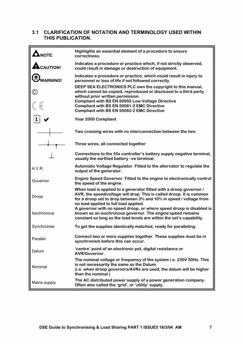
3.1 CLARIFICATION OF NOTATION AND TERMINOLOGY USED WITHIN THIS PUBLICATION.
NOTE: Highlights an essential element of a procedure to ensure correctness.
CAUTION! Indicates a procedure or practice which, if not strictly observed, could result in damage or destruction of equipment.
WARNING! Indicates a procedure or practice, which could result in injury to personnel or loss of life if not followed correctly.
DEEP SEA ELECTRONICS PLC own the copyright to this manual, which cannot be copied, reproduced or disclosed to a third party without prior written permission.
Compliant with BS EN 60950 Low Voltage Directive Compliant with BS EN 50081-2 EMC Directive Compliant with BS EN 50082-2 EMC Directive
Year 2000 Compliant
Two crossing wires with no interconnection between the two.
Three wires, all connected together
Connections to the 55x controller’s battery supply negative terminal, usually the earthed battery –ve terminal.
A.V.R. Automatic Voltage Regulator. Fitted to the alternator to regulate the output of the generator.
Governor Engine Speed Governor. Fitted to the engine to electronically control the speed of the engine.
Droop
When load is applied to a generator fitted with a droop governor / AVR, the speed/voltage will drop. This is called droop. It is common for a droop set to drop between 3% and 10% in speed / voltage from no load applied to full load applied.
Isochronous A governor with no speed droop, or where speed droop is disabled is known as an isochronous governor. The engine speed remains constant so long as the load levels are within the set’s capability.
Synchronise To get the supplies identically matched, ready for paralleling.
Parallel Connect two or more supplies together. These supplies must be in synchronism before this can occur.
Datum ‘centre’ point of an electronic pot, digital resistance or AVR/Governor.
Nominal
The nominal voltage or frequency of the system i.e. 230V 50Hz. This is not necessarily the same as the Datum. (i.e. when droop governors/AVRs are used, the datum will be higher than the nominal )
Mains supply The AC distributed power supply of a power generation company. Often also called the ‘grid’, or ‘utility’ supply.
DSE Guide to Synchronising & Load Sharing PART 1 ISSUE5 18/3/04 AM 8
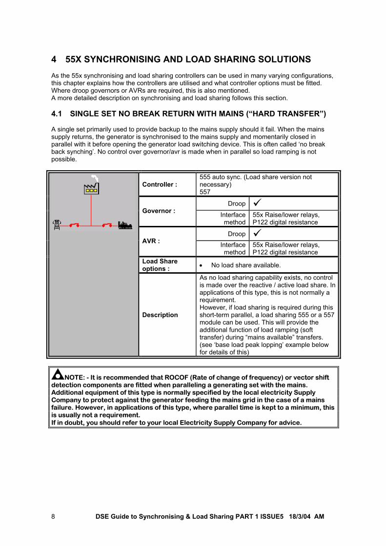
4 55X SYNCHRONISING AND LOAD SHARING SOLUTIONS As the 55x synchronising and load sharing controllers can be used in many varying configurations, this chapter explains how the controllers are utilised and what controller options must be fitted. Where droop governors or AVRs are required, this is also mentioned. A more detailed description on synchronising and load sharing follows this section. 4.1 SINGLE SET NO BREAK RETURN WITH MAINS (“HARD TRANSFER”) A single set primarily used to provide backup to the mains supply should it fail. When the mains supply returns, the generator is synchronised to the mains supply and momentarily closed in parallel with it before opening the generator load switching device. This is often called ‘no break back synching’. No control over governor/avr is made when in parallel so load ramping is not possible.
Controller : 555 auto sync. (Load share version not necessary) 557
Droop Governor : Interface
method55x Raise/lower relays, P122 digital resistance
Droop AVR : Interface
method55x Raise/lower relays, P122 digital resistance
Load Share options : • No load share available.
Description
As no load sharing capability exists, no control is made over the reactive / active load share. In applications of this type, this is not normally a requirement. However, if load sharing is required during this short-term parallel, a load sharing 555 or a 557 module can be used. This will provide the additional function of load ramping (soft transfer) during “mains available” transfers. (see ‘base load peak lopping’ example below for details of this)
NOTE: - It is recommended that ROCOF (Rate of change of frequency) or vector shift detection components are fitted when paralleling a generating set with the mains. Additional equipment of this type is normally specified by the local electricity Supply Company to protect against the generator feeding the mains grid in the case of a mains failure. However, in applications of this type, where parallel time is kept to a minimum, this is usually not a requirement. If in doubt, you should refer to your local Electricity Supply Company for advice.
DSE Guide to Synchronising & Load Sharing PART 1 ISSUE5 18/3/04 AM 9
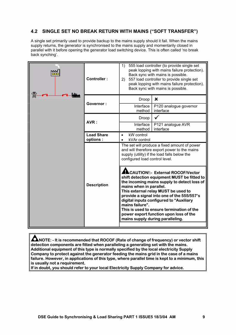
4.2 SINGLE SET NO BREAK RETURN WITH MAINS (“SOFT TRANSFER”) A single set primarily used to provide backup to the mains supply should it fail. When the mains supply returns, the generator is synchronised to the mains supply and momentarily closed in parallel with it before opening the generator load switching device. This is often called ‘no break back synching’.
Controller :
1) 555 load controller (to provide single set peak lopping with mains failure protection). Back sync with mains is possible.
2) 557 load controller to provide single set peak lopping with mains failure protection). Back sync with mains is possible.
Droop Governor : Interface
methodP120 analogue governor interface
Droop AVR : Interface
methodP121 analogue AVR interface
Load Share options :
• kW control • kVAr control
Description
The set will produce a fixed amount of power and will therefore export power to the mains supply (utility) if the load falls below the configured load control level.
CAUTION!:- External ROCOF/Vector shift detection equipment MUST be fitted to the incoming mains supply to detect loss of mains when in parallel. This external relay MUST be used to provide a signal into one of the 555/557’s digital inputs configured to “Auxiliary mains failure”. This is used to ensure termination of the power export function upon loss of the mains supply during paralleling.
NOTE: - It is recommended that ROCOF (Rate of change of frequency) or vector shift detection components are fitted when paralleling a generating set with the mains. Additional equipment of this type is normally specified by the local electricity Supply Company to protect against the generator feeding the mains grid in the case of a mains failure. However, in applications of this type, where parallel time is kept to a minimum, this is usually not a requirement. If in doubt, you should refer to your local Electricity Supply Company for advice.
DSE Guide to Synchronising & Load Sharing PART 1 ISSUE5 18/3/04 AM 10
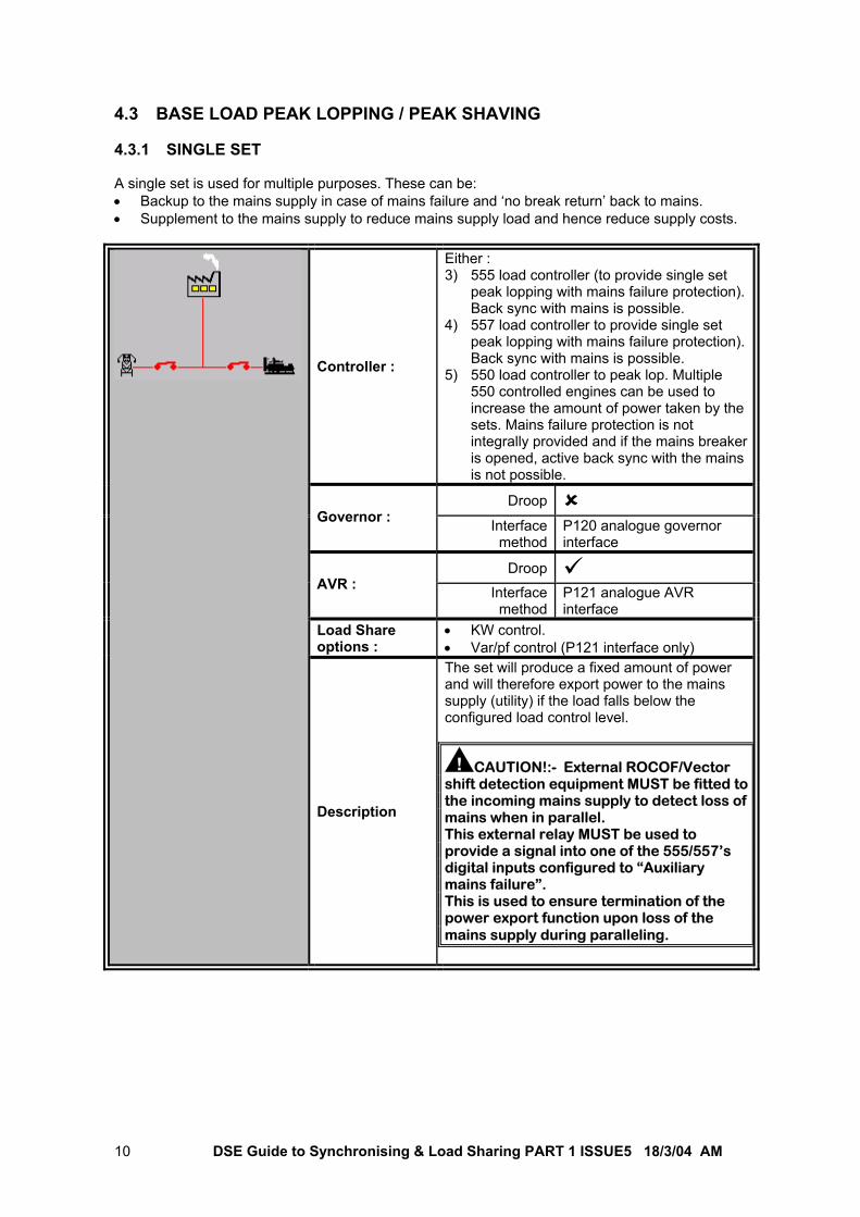
4.3 BASE LOAD PEAK LOPPING / PEAK SHAVING 4.3.1 SINGLE SET A single set is used for multiple purposes. These can be: • Backup to the mains supply in case of mains failure and ‘no break return’ back to mains. • Supplement to the mains supply to reduce mains supply load and hence reduce supply costs.
Controller :
Either : 3) 555 load controller (to provide single set
peak lopping with mains failure protection). Back sync with mains is possible.
4) 557 load controller to provide single set peak lopping with mains failure protection). Back sync with mains is possible.
5) 550 load controller to peak lop. Multiple 550 controlled engines can be used to increase the amount of power taken by the sets. Mains failure protection is not integrally provided and if the mains breaker is opened, active back sync with the mains is not possible.
Droop Governor : Interface
methodP120 analogue governor interface
Droop AVR : Interface
methodP121 analogue AVR interface
Load Share options :
• KW control. • Var/pf control (P121 interface only)
Description
The set will produce a fixed amount of power and will therefore export power to the mains supply (utility) if the load falls below the configured load control level.
CAUTION!:- External ROCOF/Vector shift detection equipment MUST be fitted to the incoming mains supply to detect loss of mains when in parallel. This external relay MUST be used to provide a signal into one of the 555/557’s digital inputs configured to “Auxiliary mains failure”. This is used to ensure termination of the power export function upon loss of the mains supply during paralleling.
DSE Guide to Synchronising & Load Sharing PART 1 ISSUE5 18/3/04 AM 11
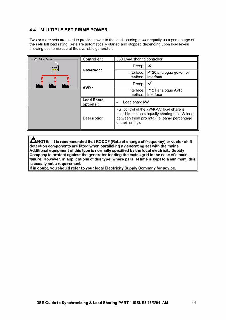
4.4 MULTIPLE SET PRIME POWER Two or more sets are used to provide power to the load, sharing power equally as a percentage of the sets full load rating. Sets are automatically started and stopped depending upon load levels allowing economic use of the available generators.
Controller : 550 Load sharing controller Droop
Governor : Interface method
P120 analogue governor interface
Droop AVR : Interface
methodP121 analogue AVR interface
Load Share options : • Load share kW
Description
Full control of the kW/KVAr load share is possible, the sets equally sharing the kW load between them pro rata (i.e. same percentage of their rating).
NOTE: - It is recommended that ROCOF (Rate of change of frequency) or vector shift detection components are fitted when paralleling a generating set with the mains. Additional equipment of this type is normally specified by the local electricity Supply Company to protect against the generator feeding the mains grid in the case of a mains failure. However, in applications of this type, where parallel time is kept to a minimum, this is usually not a requirement. If in doubt, you should refer to your local Electricity Supply Company for advice.
DSE Guide to Synchronising & Load Sharing PART 1 ISSUE5 18/3/04 AM 12
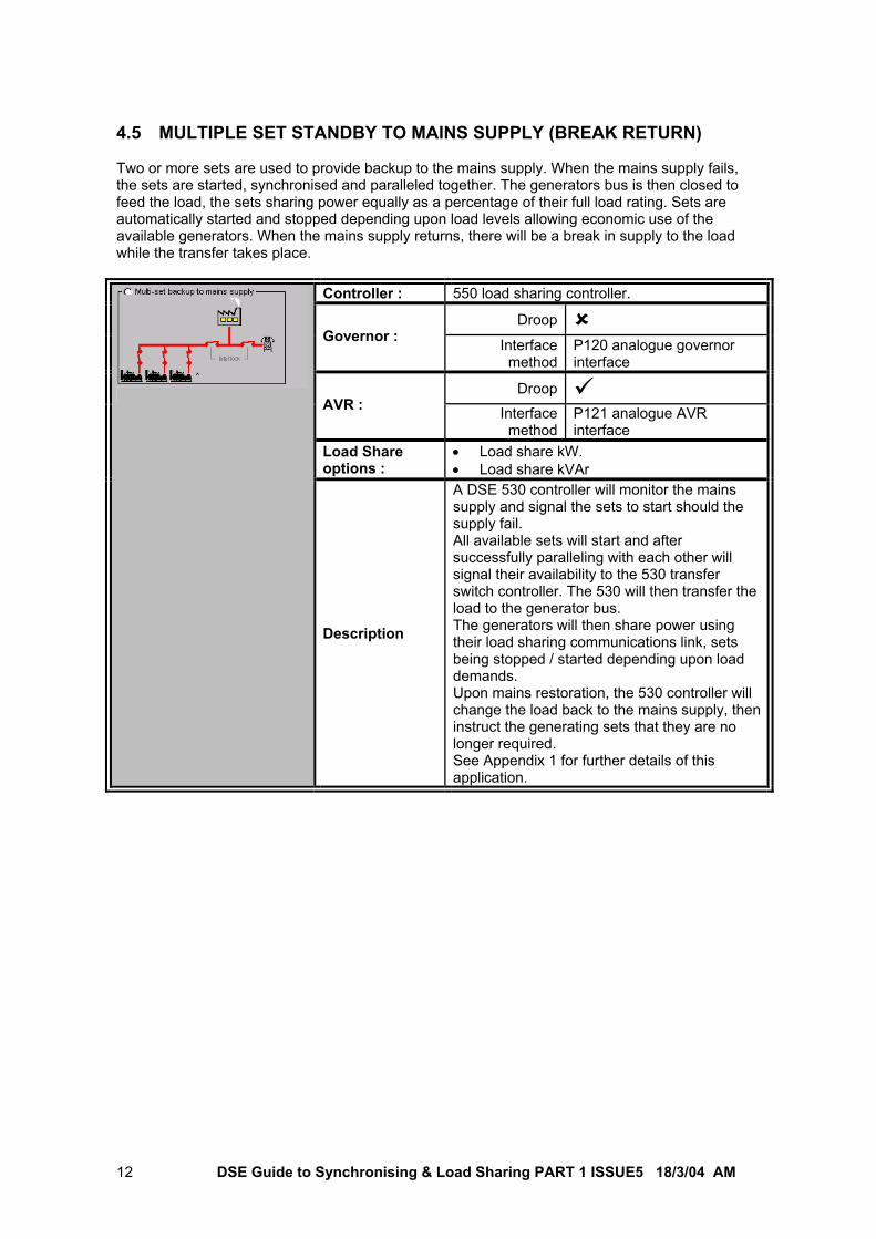
4.5 MULTIPLE SET STANDBY TO MAINS SUPPLY (BREAK RETURN) Two or more sets are used to provide backup to the mains supply. When the mains supply fails, the sets are started, synchronised and paralleled together. The generators bus is then closed to feed the load, the sets sharing power equally as a percentage of their full load rating. Sets are automatically started and stopped depending upon load levels allowing economic use of the available generators. When the mains supply returns, there will be a break in supply to the load while the transfer takes place.
Controller : 550 load sharing controller. Droop
Governor : Interface method
P120 analogue governor interface
Droop AVR : Interface
methodP121 analogue AVR interface
Load Share options :
• Load share kW. • Load share kVAr
Description
A DSE 530 controller will monitor the mains supply and signal the sets to start should the supply fail. All available sets will start and after successfully paralleling with each other will signal their availability to the 530 transfer switch controller. The 530 will then transfer the load to the generator bus. The generators will then share power using their load sharing communications link, sets being stopped / started depending upon load demands. Upon mains restoration, the 530 controller will change the load back to the mains supply, then instruct the generating sets that they are no longer required. See Appendix 1 for further details of this application.
DSE Guide to Synchronising & Load Sharing PART 1 ISSUE5 18/3/04 AM 13
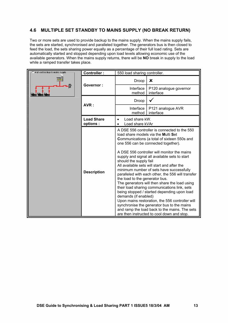
4.6 MULTIPLE SET STANDBY TO MAINS SUPPLY (NO BREAK RETURN) Two or more sets are used to provide backup to the mains supply. When the mains supply fails, the sets are started, synchronised and paralleled together. The generators bus is then closed to feed the load, the sets sharing power equally as a percentage of their full load rating. Sets are automatically started and stopped depending upon load levels allowing economic use of the available generators. When the mains supply returns, there will be NO break in supply to the load while a ramped transfer takes place.
Controller : 550 load sharing controller. Droop
Governor : Interface method
P120 analogue governor interface
Droop AVR :
Interface method
P121 analogue AVR interface
Load Share options :
• Load share kW. • Load share kVAr
Description
A DSE 556 controller is connected to the 550 load share models via the Multi Set Communications (a total of sixteen 550s and one 556 can be connected together). A DSE 556 controller will monitor the mains supply and signal all available sets to start should the supply fail All available sets will start and after the minimum number of sets have successfully paralleled with each other, the 556 will transfer the load to the generator bus. The generators will then share the load using their load sharing communications link, sets being stopped / started depending upon load demands (if enabled) Upon mains restoration, the 556 controller will synchronise the generator bus to the mains and ramp the load back to the mains. The sets are then instructed to cool down and stop.
DSE Guide to Synchronising & Load Sharing PART 1 ISSUE5 18/3/04 AM 14
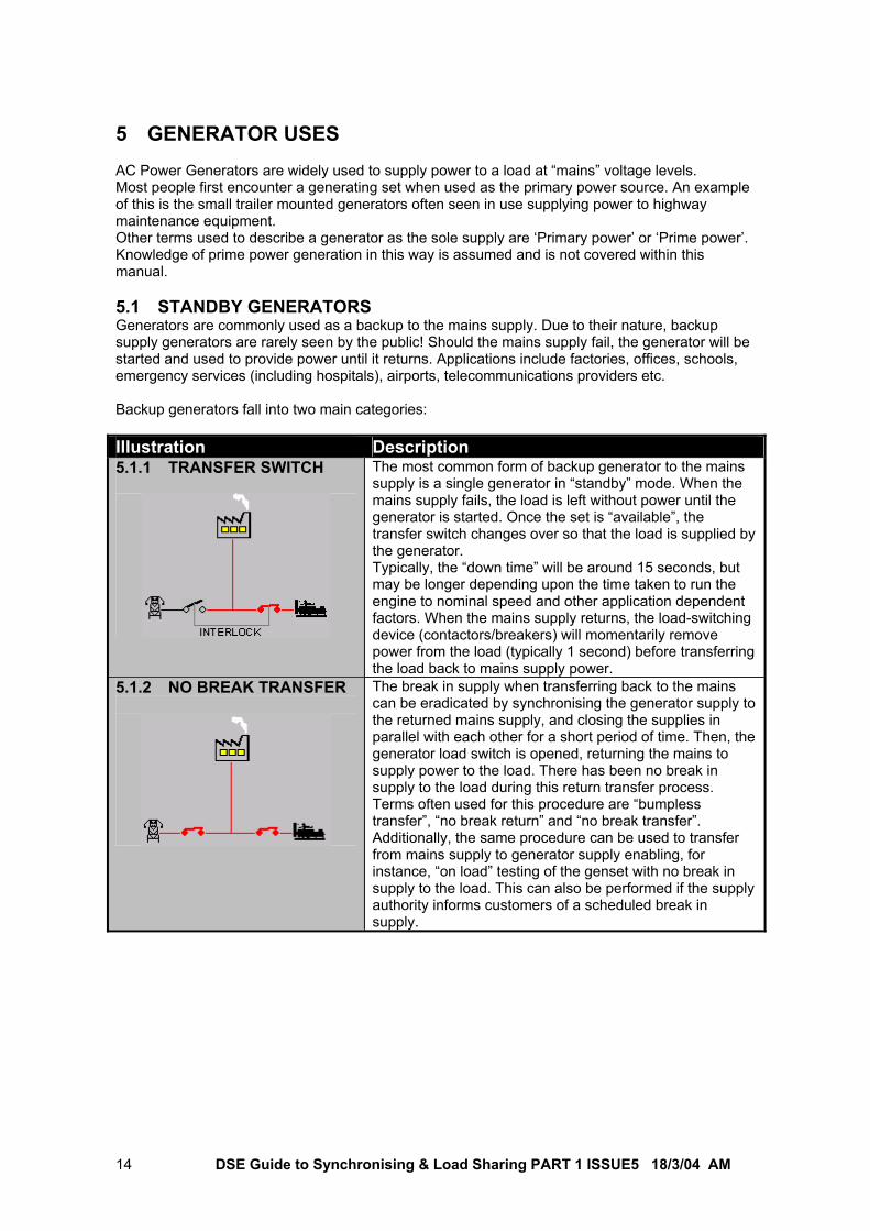
5 GENERATOR USES AC Power Generators are widely used to supply power to a load at “mains” voltage levels. Most people first encounter a generating set when used as the primary power source. An example of this is the small trailer mounted generators often seen in use supplying power to highway maintenance equipment. Other terms used to describe a generator as the sole supply are ‘Primary power’ or ‘Prime power’. Knowledge of prime power generation in this way is assumed and is not covered within this manual. 5.1 STANDBY GENERATORS Generators are commonly used as a backup to the mains supply. Due to their nature, backup supply generators are rarely seen by the public! Should the mains supply fail, the generator will be started and used to provide power until it returns. Applications include factories, offices, schools, emergency services (including hospitals), airports, telecommunications providers etc. Backup generators fall into two main categories: Illustration Description 5.1.1 TRANSFER SWITCH
The most common form of backup generator to the mains supply is a single generator in “standby” mode. When the mains supply fails, the load is left without power until the generator is started. Once the set is “available”, the transfer switch changes over so that the load is supplied by the generator. Typically, the “down time” will be around 15 seconds, but may be longer depending upon the time taken to run the engine to nominal speed and other application dependent factors. When the mains supply returns, the load-switching device (contactors/breakers) will momentarily remove power from the load (typically 1 second) before transferring the load back to mains supply power.
5.1.2 NO BREAK TRANSFER
The break in supply when transferring back to the mains can be eradicated by synchronising the generator supply to the returned mains supply, and closing the supplies in parallel with each other for a short period of time. Then, the generator load switch is opened, returning the mains to supply power to the load. There has been no break in supply to the load during this return transfer process. Terms often used for this procedure are “bumpless transfer”, “no break return” and “no break transfer”. Additionally, the same procedure can be used to transfer from mains supply to generator supply enabling, for instance, “on load” testing of the genset with no break in supply to the load. This can also be performed if the supply authority informs customers of a scheduled break in supply.
DSE Guide to Synchronising & Load Sharing PART 1 ISSUE5 18/3/04 AM 15
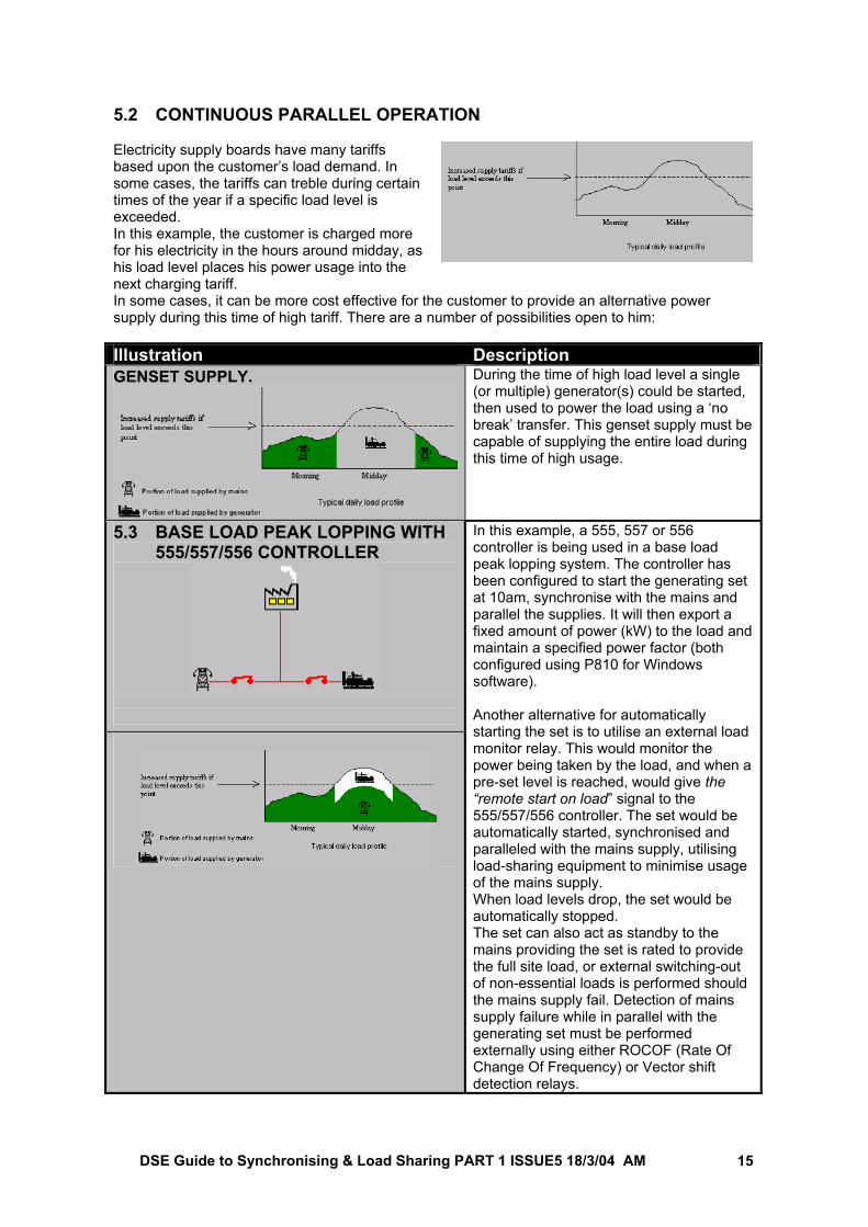
5.2 CONTINUOUS PARALLEL OPERATION Electricity supply boards have many tariffs based upon the customer’s load demand. In some cases, the tariffs can treble during certain times of the year if a specific load level is exceeded. In this example, the customer is charged more for his electricity in the hours around midday, as his load level places his power usage into the next charging tariff.
In some cases, it can be more cost effective for the customer to provide an alternative power supply during this time of high tariff. There are a number of possibilities open to him: Illustration Description GENSET SUPPLY. During the time of high load level a single
(or multiple) generator(s) could be started, then used to power the load using a ‘no break’ transfer. This genset supply must be capable of supplying the entire load during this time of high usage.
5.3 BASE LOAD PEAK LOPPING WITH 555/557/556 CONTROLLER
In this example, a 555, 557 or 556 controller is being used in a base load peak lopping system. The controller has been configured to start the generating set at 10am, synchronise with the mains and parallel the supplies. It will then export a fixed amount of power (kW) to the load and maintain a specified power factor (both configured using P810 for Windows software). Another alternative for automatically starting the set is to utilise an external load monitor relay. This would monitor the power being taken by the load, and when a pre-set level is reached, would give the “remote start on load” signal to the 555/557/556 controller. The set would be automatically started, synchronised and paralleled with the mains supply, utilising load-sharing equipment to minimise usage of the mains supply. When load levels drop, the set would be automatically stopped. The set can also act as standby to the mains providing the set is rated to provide the full site load, or external switching-out of non-essential loads is performed should the mains supply fail. Detection of mains supply failure while in parallel with the generating set must be performed externally using either ROCOF (Rate Of Change Of Frequency) or Vector shift detection relays.
DSE Guide to Synchronising & Load Sharing PART 1 ISSUE5 18/3/04 AM 16
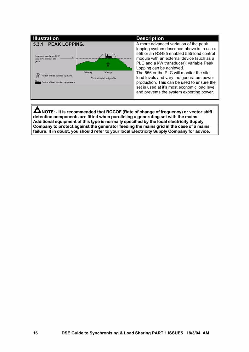
Illustration Description 5.3.1 PEAK LOPPING.
A more advanced variation of the peak lopping system described above is to use a 556 or an RS485 enabled 555 load control module with an external device (such as a PLC and a kW transducer), variable Peak Lopping can be achieved. The 556 or the PLC will monitor the site load levels and vary the generators power production. This can be used to ensure the set is used at it’s most economic load level, and prevents the system exporting power.
NOTE: - It is recommended that ROCOF (Rate of change of frequency) or vector shift detection components are fitted when paralleling a generating set with the mains. Additional equipment of this type is normally specified by the local electricity Supply Company to protect against the generator feeding the mains grid in the case of a mains failure. If in doubt, you should refer to your local Electricity Supply Company for advice.
DSE Guide to Synchronising & Load Sharing PART 1 ISSUE5 18/3/04 AM 17
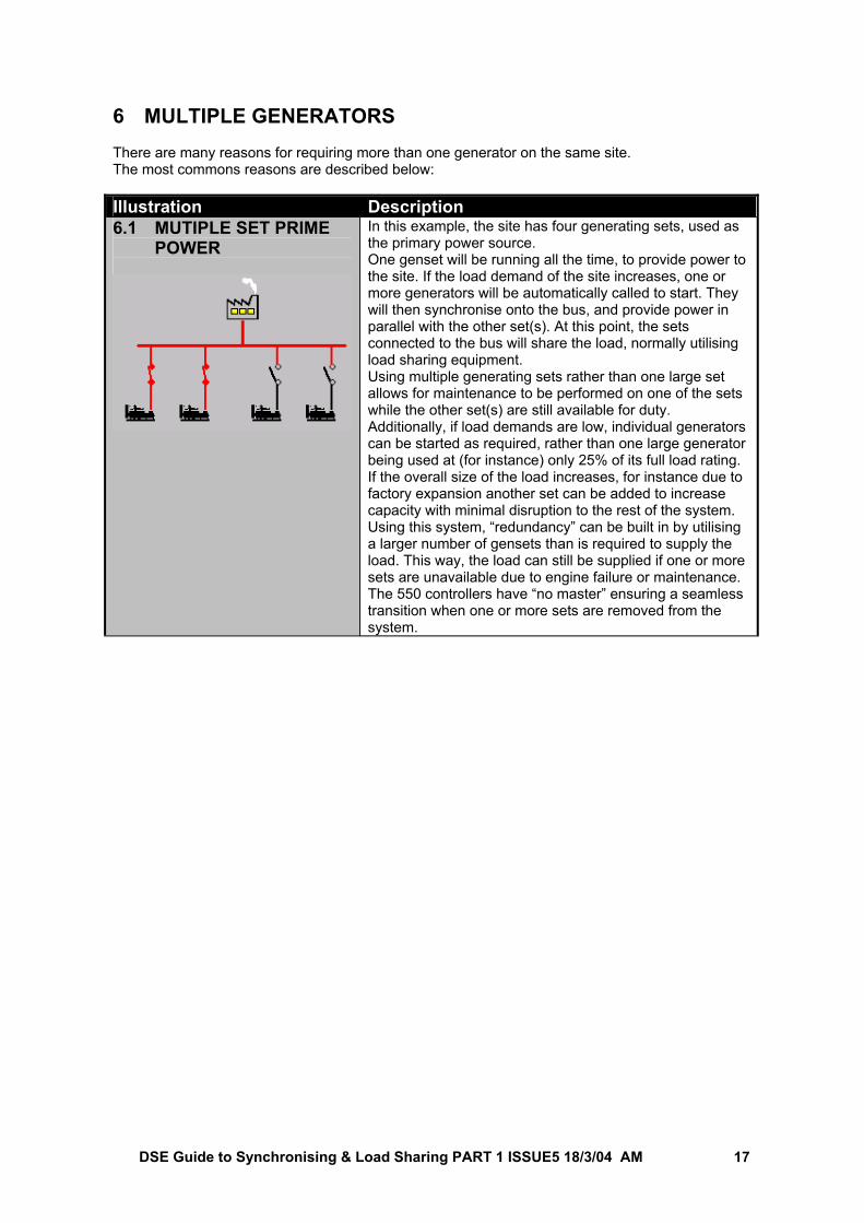
6 MULTIPLE GENERATORS There are many reasons for requiring more than one generator on the same site. The most commons reasons are described below: Illustration Description 6.1 MUTIPLE SET PRIME
POWER
In this example, the site has four generating sets, used as the primary power source. One genset will be running all the time, to provide power to the site. If the load demand of the site increases, one or more generators will be automatically called to start. They will then synchronise onto the bus, and provide power in parallel with the other set(s). At this point, the sets connected to the bus will share the load, normally utilising load sharing equipment. Using multiple generating sets rather than one large set allows for maintenance to be performed on one of the sets while the other set(s) are still available for duty. Additionally, if load demands are low, individual generators can be started as required, rather than one large generator being used at (for instance) only 25% of its full load rating. If the overall size of the load increases, for instance due to factory expansion another set can be added to increase capacity with minimal disruption to the rest of the system. Using this system, “redundancy” can be built in by utilising a larger number of gensets than is required to supply the load. This way, the load can still be supplied if one or more sets are unavailable due to engine failure or maintenance. The 550 controllers have “no master” ensuring a seamless transition when one or more sets are removed from the system.

DSE Guide to Synchronising & Load Sharing PART 1 ISSUE5 18/3/04 AM 18
Illustration Description 6.2 MULTIPLE SETS
PROVIDING STANDBY TO THE MAINS SUPPLY
If multiple gensets in parallel are used to backup the mains supply, care should be taken when designing the system. In the example above for instance, should the mains supply fail, two possibilities exist. Firstly, if only two generating sets are providing power to the bus, they must be capable of supplying the currently active load. Secondly, if none of the sets are available, they will all start up simultaneously. The first set will close onto the dead bus, and supply power to the load. Again, the set must be capable of supplying this power to the currently active load. Two solutions exist : a) Ensure each generating set is capable of supplying the
entire load so that the above situations will not occur. b) Ensure before closing the load switch and powering
the load with the generating sets, that all of the generating sets are available and synchronised onto the generator bus. While running in this manner, not in parallel with the mains supply, this is called ‘islanded mode’.
6.2.1 LOAD-SWITCHING USING 530 ATS The DSE 530 automatic transfer switch can be used to monitor the mains supply to ensure it is within limits. Should the mains supply fail, the 530 can be used to ‘remote start on load demand’ the 550 controllers used in the example shown. All sets in the system will start together. The first available set will close onto the dead bus, also closing it’s load switch auxiliary contact. The other generating sets will synchronise onto the generator bus, and then close in parallel with it. Connect all of the generating set load switch auxiliary contacts in series and connecting into the auxiliary generator ready input (terminal 10) of the DSE 530 automatic transfer switch in conjunction with further external relay logic to latch this signal. (Further details of this can be found in Appendix 1 of this publication). The DSE 530 module will sense the generator bus voltage and frequency, and once within limits will ‘wait’ for the presence of the auxiliary generator ready input. This signifies the correct closure of all sets in the system onto the generator bus. The mains – generator load transfer is then performed by the 530 automatic transfer switch controller.
DSE Guide to Synchronising & Load Sharing PART 1 ISSUE5 18/3/04 AM 19
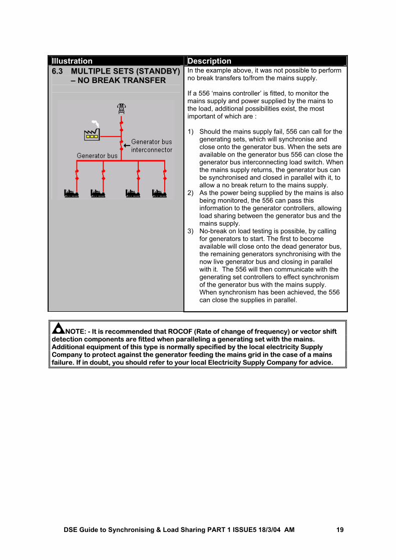
Illustration Description 6.3 MULTIPLE SETS (STANDBY)
– NO BREAK TRANSFER
In the example above, it was not possible to perform no break transfers to/from the mains supply. If a 556 ‘mains controller’ is fitted, to monitor the mains supply and power supplied by the mains to the load, additional possibilities exist, the most important of which are : 1) Should the mains supply fail, 556 can call for the
generating sets, which will synchronise and close onto the generator bus. When the sets are available on the generator bus 556 can close the generator bus interconnecting load switch. When the mains supply returns, the generator bus can be synchronised and closed in parallel with it, to allow a no break return to the mains supply.
2) As the power being supplied by the mains is also being monitored, the 556 can pass this information to the generator controllers, allowing load sharing between the generator bus and the mains supply.
3) No-break on load testing is possible, by calling for generators to start. The first to become available will close onto the dead generator bus, the remaining generators synchronising with the now live generator bus and closing in parallel with it. The 556 will then communicate with the generating set controllers to effect synchronism of the generator bus with the mains supply. When synchronism has been achieved, the 556 can close the supplies in parallel.
NOTE: - It is recommended that ROCOF (Rate of change of frequency) or vector shift detection components are fitted when paralleling a generating set with the mains. Additional equipment of this type is normally specified by the local electricity Supply Company to protect against the generator feeding the mains grid in the case of a mains failure. If in doubt, you should refer to your local Electricity Supply Company for advice.
DSE Guide to Synchronising & Load Sharing PART 1 ISSUE5 18/3/04 AM 20
7 LOAD SHARING 7.1 ACTIVE POWER SHARING We have discussed the synchronising of one or more supplies to the mains or bus supply. Once these supplies are closed in parallel with each other, the power will be shared between the supplies depending upon the generating set characteristics. Consider firstly, two generators operating in droop, closed together in parallel. Providing that the governors are set correctly, the ratios of the power supplied to the load by each generator will be proportional to the ratio of governor droop in each system. For instance for a load of 100kW, and two generators with 3% speed droop, the generators will equally share the load, each one supplying 50kW. Consider now one generator operating in droop, connected in parallel with the mains supply, with the governor adjusted so that the mains and the generator are sharing the load between them. “Backing off” the governor, decreasing the engine’s fuel supply, will result in the mains ‘motoring’ the alternator. The generator is being “reverse powered”, absorbing power from the mains supply and not supplying any power to the load. Instructing the governor to increase fuel to the engine will also have no effect on engine speed because the generator is “tied” to the mains. Instead, the generator will begin to supply power to the load. Further increasing the fuel supply increases the amount of power supplied by the generator. This in turn decreases the amount of power supplied by the mains. This is known as Kilowatt (kW) export. This can be taken a step further, by paralleling multiple generating sets, all operating isochronously (zero droop). Utilising an active load-sharing controller, precise changes can be made to the amount of power supplied to the load by each generating set. This is achieved by altering the amount of fuel supplied to the engine, and monitoring the amount of power supplied by the set. Each controller can communicate with the others, passing information regarding load levels. This can also be used to bring in or drop off other generating sets as load demands change. 7.2 REACTIVE POWER SHARING Again, consider two identical generating sets closed together in parallel. Each generator has a ‘droop kit’ fitted to the AVR and the field current of each generator is the same. In this situation, they will both supply equal reactive power (kVAr) to the load. Adjusting the amount of field excitation in one of the generators has the effect of that generator supplying more or less of the reactive power to the load, matched by an equal drop in the reactive power supplied by the other generator. Uses of reactive power control include: 1) Where multiple generators are used in parallel with each other, the AVRs droop kits will ensure
that the reactive power is equalised between the sets, removing circulating currents caused by imbalance in the reactive power (VAr) supplied by the paralleled generating sets. This circulating current generates heat in the alternator windings, which has the effect of limiting active power (kW) output, reducing the efficiency of the generating set. If left unchecked, excess circulating current can also damage the alternator windings.
2) Power factor control or VAr control. This feature maintains a specific power factor where one generating set is used in parallel with the mains supply. This is normally used so that the generator maintains its VArs to keep its output at the site load’s average power factor level, to minimise demands on the mains supply.
DSE Guide to Synchronising & Load Sharing PART 1 ISSUE5 18/3/04 AM 21
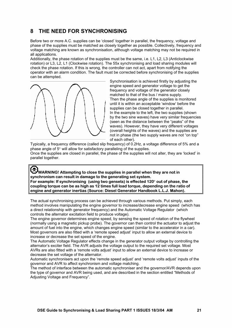
8 THE NEED FOR SYNCHRONISING Before two or more A.C. supplies can be ‘closed’ together in parallel, the frequency, voltage and phase of the supplies must be matched as closely together as possible. Collectively, frequency and voltage matching are known as synchronisation, although voltage matching may not be required in all applications. Additionally, the phase rotation of the supplies must be the same, i.e. L1, L2, L3 (Anticlockwise rotation) or L3, L2, L1 (Clockwise rotation). The 55x synchronising and load sharing modules will check the phase rotation. If this is wrong, the controller can not act, apart from notifying the operator with an alarm condition. The fault must be corrected before synchronising of the supplies can be attempted.
Synchronisation is achieved firstly by adjusting the engine speed and generator voltage to get the frequency and voltage of the generator closely matched to that of the bus / mains supply. Then the phase angle of the supplies is monitored until it is within an acceptable ‘window’ before the supplies can be closed together in parallel. In the example to the left, the two supplies (shown by the two sine waves) have very similar frequencies (seen as the distance between the “peaks” of the waves). However, they have very different voltages (overall heights of the waves) and the supplies are not in phase (the two supply waves are not “on top” of each other).
Typically, a frequency difference (called slip frequency) of 0.2Hz, a voltage difference of 5% and a phase angle of 5° will allow for satisfactory paralleling of the supplies. Once the supplies are closed in parallel, the phase of the supplies will not alter, they are ‘locked’ in parallel together.
WARNING! Attempting to close the supplies in parallel when they are not in synchronism can result in damage to the generating set system. For example: If synchronising (using two gensets) is effected 120° out of phase, the coupling torque can be as high as 12 times full load torque, depending on the ratio of engine and generator inertias (Source: Diesel Generator Handbook L.L.J. Mahon). The actual synchronising process can be achieved through various methods. Put simply, each method involves manipulating the engine governor to increase/decrease engine speed (which has a direct relationship with generator frequency) and the Automatic Voltage Regulator (which controls the alternator excitation field to produce voltage). The engine governor determines engine speed, by sensing the speed of rotation of the flywheel (normally using a magnetic pickup probe). The governor can then control the actuator to adjust the amount of fuel into the engine, which changes engine speed (similar to the accelerator in a car). Most governors are also fitted with a ‘remote speed adjust’ input to allow an external device to increase or decrease the set speed of the engine. The Automatic Voltage Regulator effects change in the generator output voltage by controlling the alternator’s exciter field. The AVR adjusts the voltage output to the required set voltage. Most AVRs are also fitted with a ‘remote volts adjust’ input to allow an external device to increase or decrease the set voltage of the alternator. Automatic synchronisers act upon the ‘remote speed adjust’ and ‘remote volts adjust’ inputs of the governor and AVR to affect synchronism and voltage matching. The method of interface between the automatic synchroniser and the governor/AVR depends upon the type of governor and AVR being used, and are described in the section entitled “Methods of Adjusting Voltage and Frequency”.
DSE Guide to Synchronising & Load Sharing PART 1 ISSUE5 18/3/04 AM 22
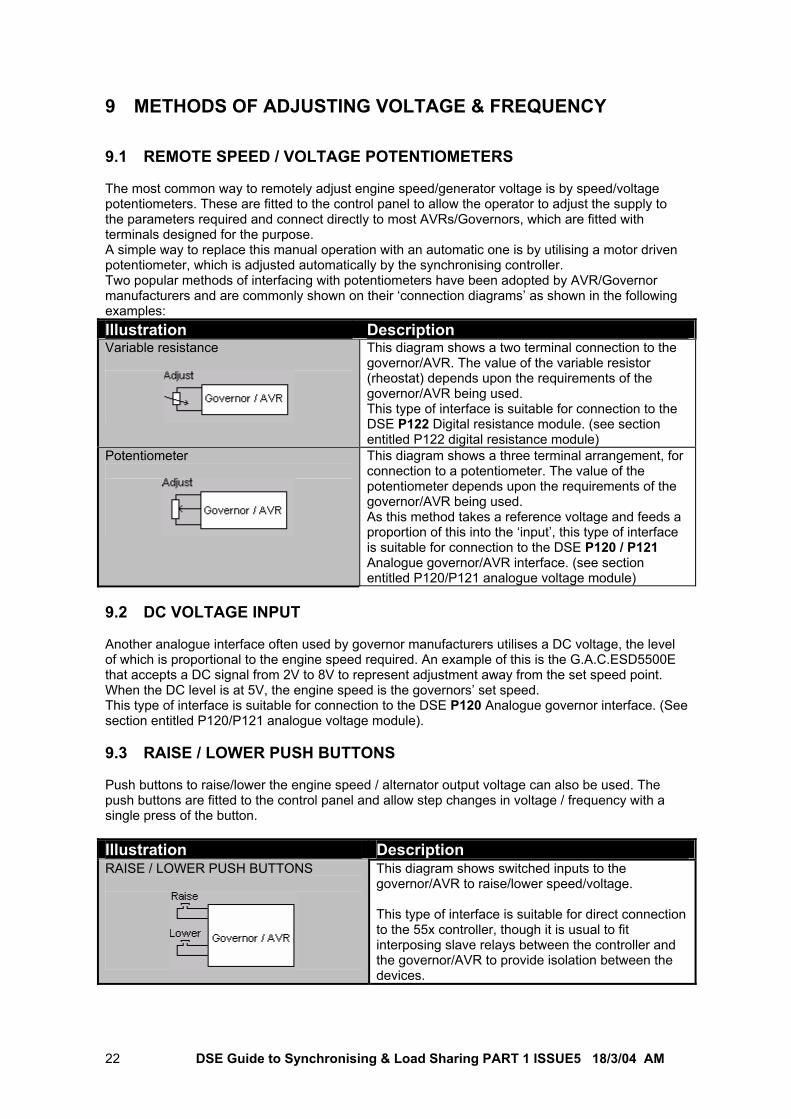
9 METHODS OF ADJUSTING VOLTAGE & FREQUENCY 9.1 REMOTE SPEED / VOLTAGE POTENTIOMETERS The most common way to remotely adjust engine speed/generator voltage is by speed/voltage potentiometers. These are fitted to the control panel to allow the operator to adjust the supply to the parameters required and connect directly to most AVRs/Governors, which are fitted with terminals designed for the purpose. A simple way to replace this manual operation with an automatic one is by utilising a motor driven potentiometer, which is adjusted automatically by the synchronising controller. Two popular methods of interfacing with potentiometers have been adopted by AVR/Governor manufacturers and are commonly shown on their ‘connection diagrams’ as shown in the following examples: Illustration Description Variable resistance
This diagram shows a two terminal connection to the governor/AVR. The value of the variable resistor (rheostat) depends upon the requirements of the governor/AVR being used. This type of interface is suitable for connection to the DSE P122 Digital resistance module. (see section entitled P122 digital resistance module)
Potentiometer
This diagram shows a three terminal arrangement, for connection to a potentiometer. The value of the potentiometer depends upon the requirements of the governor/AVR being used. As this method takes a reference voltage and feeds a proportion of this into the ‘input’, this type of interface is suitable for connection to the DSE P120 / P121 Analogue governor/AVR interface. (see section entitled P120/P121 analogue voltage module)
9.2 DC VOLTAGE INPUT Another analogue interface often used by governor manufacturers utilises a DC voltage, the level of which is proportional to the engine speed required. An example of this is the G.A.C.ESD5500E that accepts a DC signal from 2V to 8V to represent adjustment away from the set speed point. When the DC level is at 5V, the engine speed is the governors’ set speed. This type of interface is suitable for connection to the DSE P120 Analogue governor interface. (See section entitled P120/P121 analogue voltage module). 9.3 RAISE / LOWER PUSH BUTTONS Push buttons to raise/lower the engine speed / alternator output voltage can also be used. The push buttons are fitted to the control panel and allow step changes in voltage / frequency with a single press of the button. Illustration Description RAISE / LOWER PUSH BUTTONS
This diagram shows switched inputs to the governor/AVR to raise/lower speed/voltage. This type of interface is suitable for direct connection to the 55x controller, though it is usual to fit interposing slave relays between the controller and the governor/AVR to provide isolation between the devices.
DSE Guide to Synchronising & Load Sharing PART 1 ISSUE5 18/3/04 AM 23
10 REQUIREMENTS FOR SYNCHRONISATION AND LOAD
SHARING 10.1 GOVERNOR AND GOVERNOR INTERFACE 10.1.1 ISOCHRONOUS ACTIVE LOAD SHARING For synchronising purposes where active load sharing is employed, isochronous governors with sync/load share DC analogue inputs should be used. Isochronous active load sharing demands a fast response to variations in the measured parameters. For this reason, we recommend the use of the P120 analogue governor interface module in applications of this type. Isochronous active load sharing is typically employed in mains peak lopping or multiple set prime power applications. 10.1.2 DROOP ACTIVE LOAD SHARING Droop active load sharing is typically used in no-break changeover systems, where control of the active load (kW) share is not made during the parallel time. A droop governor must be fitted, with a small amount of droop configured (typically 3% to 5%). Droop provides for a small lowering of engine speed, as the load on the set is increased.
DSE Guide to Synchronising & Load Sharing PART 1 ISSUE5 18/3/04 AM 24
10.2 GENERATOR AND AVR 10.2.1 DROOP REACTIVE LOAD SHARING Droop reactive load sharing is typically used in MultiSet prime power applications to remove circulating currents between the sets. Voltage matching is not always required so long as the AVRs are correctly set to closely match the voltages between the different sets in the system. Reactive circulating currents are removed by the addition of the AVR “Droop kit”, and no control is made over the reactive power by the load sharing controller. Where voltage matching is required, the generator must be fitted with a remotely adjustable AVR (automatic voltage regulator). When utilising the 55x load sharing controller to perform power factor control or reactive load control, the AVR must be fitted with Quadrature Droop Compensation (QDC).
NOTE: - Quadrature Droop Compensation (QDC or ‘Quad Droop’ for short) is also sometimes referred to as Quadrature Current Compensation (QCC) 10.2.2 AUTOMATIC REACTIVE LOAD SHARE Automatic reactive load control is used in multiset load sharing applications to minimise the circulating currents between sets. AVR droop kits go some way to providing this function but the addition of automatic control provided by the 550 can reduce the circulating current even further. The generator must be fitted with a remotely adjustable AVR (automatic voltage regulator). The 55x Load sharing controller can take full control over the reactive power supplied by the generating set.
WARNING: - Care should be taken with respect to the grounding methodology of the generator neutrals, particularly where alternators with differing winding pitches are to be paralleled.
10.2.3 AUTOMATIC REACTIVE LOAD CONTROL Automatic reactive load control is typically used in peak lopping / peak shaving applications to minimise the kVAr demands on the mains supply. For voltage matching with the mains/utility supply, the generator must be fitted with a remotely adjustable AVR (automatic voltage regulator). The 55x Load sharing controller can take full control over the reactive power supplied by the generating set. This can be used for exporting a fixed amount of power (VAr control)
WARNING: - Care should be taken with respect to the grounding methodology of the generator neutrals, particularly where alternators with differing winding pitches are to be paralleled.
DSE Guide to Synchronising & Load Sharing PART 1 ISSUE5 18/3/04 AM 25
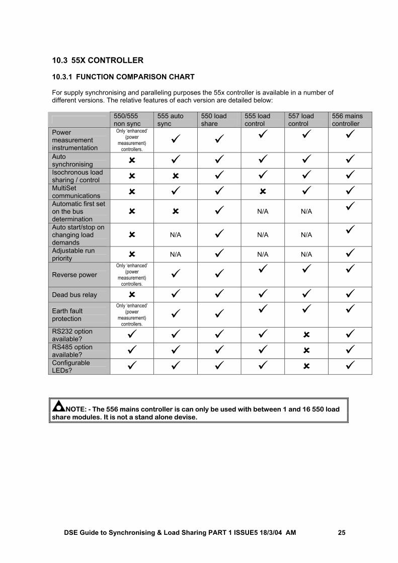
10.3 55X CONTROLLER 10.3.1 FUNCTION COMPARISON CHART For supply synchronising and paralleling purposes the 55x controller is available in a number of different versions. The relative features of each version are detailed below:
550/555 non sync
555 auto sync
550 load share
555 load control
557 load control
556 mains controller
Power measurement instrumentation
Only ‘enhanced’ (power
measurement) controllers.
Auto synchronising Isochronous load sharing / control MultiSet communications Automatic first set on the bus determination
N/A N/A
Auto start/stop on changing load demands
N/A N/A N/A
Adjustable run priority N/A N/A N/A
Reverse power Only ‘enhanced’
(power measurement)
controllers.
Dead bus relay Earth fault protection
Only ‘enhanced’ (power
measurement) controllers.
RS232 option available? RS485 option available? Configurable LEDs?
NOTE: - The 556 mains controller is can only be used with between 1 and 16 550 load share modules. It is not a stand alone devise.
DSE Guide to Synchronising & Load Sharing PART 1 ISSUE5 18/3/04 AM 26
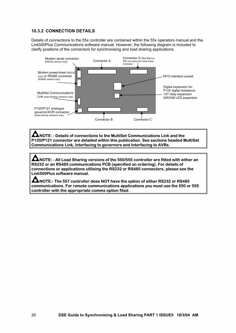
10.3.2 CONNECTION DETAILS Details of connections to the 55x controller are contained within the 55x operators manual and the Link500Plus Communications software manual. However, the following diagram is included to clarify positions of the connectors for synchronising and load sharing applications.
NOTE: - Details of connections to the MultiSet Communications Link and the P120/P121 connector are detailed within this publication. See sections headed MultiSet Communications Link, Interfacing to governors and Interfacing to AVRs.
NOTE: - All Load Sharing versions of the 550/555 controller are fitted with either an RS232 or an RS485 communications PCB (specified on ordering). For details of connections or applications utilising the RS232 or RS485 connectors, please see the Link500Plus software manual.
NOTE:- The 557 controller does NOT have the option of either RS232 or RS485 communications. For remote communications applications you must use the 550 or 555 controller with the appropriate comms option fited.
P810 interface socket
Digital expansion for: P122 digital resistance 157 relay expansion 545/548 LED expansion
Modem serial connector (RS232 version only)
Modem power/reset (RS232 only) or RS485 connector (RS485 version only)
MultiSet Communications Link (load sharing versions only)
P120/P121 analogue governor/AVR connector (load sharing versions only)
Connector A Connector D (Not fitted to 550 non-sync/non load share modules)
Connector B Connector C
DSE Guide to Synchronising & Load Sharing PART 1 ISSUE5 18/3/04 AM 27
10.3.3 AUTOMATIC SYNCHRONISING Automatic synchronising is the control over engine speed and generator output volts prior to the actual paralleling of the supplies. All ‘auto-sync’ and ‘load-share’ versions of the 55x controller can perform this function, although some governors/AVRs will require an external interface device (See sections entitled P120/P121 analogue voltage module and P122 Digital resistance module). 10.3.4 DROOP LOAD SHARING Droop load sharing is synchronising and closing the generator supplies in parallel. Then, utilising the relative droops of the systems to share power proportional to their droop ratios. No external control is made over the power share, and hence it is not necessary to use the load-sharing version of the 55x controller. The auto-synchronising version of the controller can be used to control the governor and AVR to effect synchronism and close the supplies in parallel. Multi-set droop load sharing Using the auto synchronising 550 controller, it is possible to parallel multiple sets, and share the load equally between them. No other control over the load sharing is necessary as this is taken care of by the droop in the systems. However, unless the governors are identically matched and set, the load share will not be equal. A very small difference in governor characteristics will lead to a large difference in load shares. Additionally as load levels increase though, the generators output frequency will lower due to the governor droop. If these issues cannot be accepted, they can be eradicated by the use of the 550 load-sharing controller.
NOTE: - Multiple identically rated sets running in parallel must have identical droop settings on their governors/AVRs to ensure equal load sharing between the generators. Non identical droop settings will result in sharing of the load proportional to the droop ratios of the sets. Single set – mains supply droop load sharing The auto synchronising 555 controller (again without the load sharing option) can be used in “no break return” duty with the mains supply. The supplies are only closed in parallel for a very short time. The amount of power being supplied by the generator at this time is dependent upon the governor setting. The 55x module has no control over the power sharing, but in this application, it is not normally a requirement.
DSE Guide to Synchronising & Load Sharing PART 1 ISSUE5 18/3/04 AM 28
10.3.5 ISOCHRONOUS LOAD SHARING Isochronous load sharing is the use of isochronous (zero droop) governors, with full automatic control over load sharing (i.e. the amount of power supplied by each set). When either off load, or on load, the generators output frequency will remain the same (i.e. 50Hz). The modules (when used in a MultiSet system) communicate to establish total system load. This data is then used (when the controllers are suitably configured) to decide whether it is necessary to call more sets for duty as the load levels increase. Additionally sets are automatically unloaded and removed from the bus if the load level falls low enough to allow this. This allows the generating sets to be used at a more economical level by ensuring the available (gensets currently running) capacity is close to the actual demand. This reduces the amount of unloaded engines that are running, hence improving efficiency and lowering fuel costs. For isochronous load sharing, the governor must be controlled by the P120 analogue governor interface module.
NOTE: - It is recommended that ROCOF (Rate of change of frequency) or vector shift detection components are fitted when paralleling a generating set with the mains. Additional equipment of this type is normally specified by the local electricity Supply Company to protect against the generator feeding the mains grid in the case of a mains failure. If in doubt, you should refer to your local Electricity Supply Company for advice.
DSE Guide to Synchronising & Load Sharing PART 1 ISSUE5 18/3/04 AM 29
11 LOAD SWITCHING DEVICES
The paralleling of two or more supplies requires that the switching of the supplies be performed as close to zero phase as possible. The check sync feature of the 55x synchronising and load sharing controller can accurately measure the phase, and when within the ‘check sync’ window can issue the load switching closure signal within a few milliseconds. However, there will be a delay in the actual operation and physical movement of the switching device that must be minimised and taken into account when designing and commissioning any paralleling system.
11.1 CHOOSING A LOAD SWITCHING DEVICE
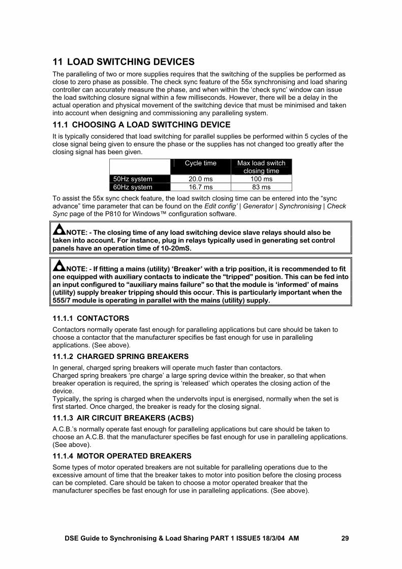
It is typically considered that load switching for parallel supplies be performed within 5 cycles of the close signal being given to ensure the phase or the supplies has not changed too greatly after the closing signal has been given.
Cycle time Max load switch closing time
50Hz system 20.0 ms 100 ms 60Hz system 16.7 ms 83 ms
To assist the 55x sync check feature, the load switch closing time can be entered into the “sync advance” time parameter that can be found on the Edit config’ | Generator | Synchronising | Check Sync page of the P810 for Windows™ configuration software.
NOTE: - The closing time of any load switching device slave relays should also be taken into account. For instance, plug in relays typically used in generating set control panels have an operation time of 10-20mS.
NOTE: - If fitting a mains (utility) ‘Breaker’ with a trip position, it is recommended to fit one equipped with auxiliary contacts to indicate the “tripped” position. This can be fed into an input configured to “auxiliary mains failure” so that the module is ‘informed’ of mains (utility) supply breaker tripping should this occur. This is particularly important when the 555/7 module is operating in parallel with the mains (utility) supply. 11.1.1 CONTACTORS
Contactors normally operate fast enough for paralleling applications but care should be taken to choose a contactor that the manufacturer specifies be fast enough for use in paralleling applications. (See above).
11.1.2 CHARGED SPRING BREAKERS
In general, charged spring breakers will operate much faster than contactors. Charged spring breakers ‘pre charge’ a large spring device within the breaker, so that when breaker operation is required, the spring is ‘released’ which operates the closing action of the device. Typically, the spring is charged when the undervolts input is energised, normally when the set is first started. Once charged, the breaker is ready for the closing signal.
11.1.3 AIR CIRCUIT BREAKERS (ACBS)
A.C.B.’s normally operate fast enough for paralleling applications but care should be taken to choose an A.C.B. that the manufacturer specifies be fast enough for use in paralleling applications. (See above).
11.1.4 MOTOR OPERATED BREAKERS
Some types of motor operated breakers are not suitable for paralleling operations due to the excessive amount of time that the breaker takes to motor into position before the closing process can be completed. Care should be taken to choose a motor operated breaker that the manufacturer specifies be fast enough for use in paralleling applications. (See above).
DSE Guide to Synchronising & Load Sharing PART 1 ISSUE5 18/3/04 AM 30
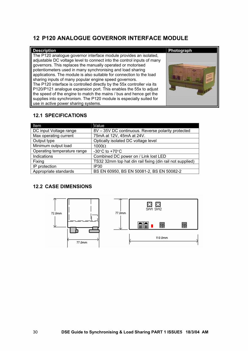
12 P120 ANALOGUE GOVERNOR INTERFACE MODULE Description Photograph The P120 analogue governor interface module provides an isolated, adjustable DC voltage level to connect into the control inputs of many governors. This replaces the manually operated or motorised potentiometers used in many synchronising and load sharing applications. The module is also suitable for connection to the load sharing inputs of many popular engine speed governors. The P120 interface is controlled directly by the 55x controller via its P120/P121 analogue expansion port. This enables the 55x to adjust the speed of the engine to match the mains / bus and hence get the supplies into synchronism. The P120 module is especially suited for use in active power sharing systems. 12.1 SPECIFICATIONS Item Value DC input Voltage range 8V – 35V DC continuous. Reverse polarity protected Max operating current 75mA at 12V, 45mA at 24V. Output type Optically isolated DC voltage level Minimum output load 1000Ω Operating temperature range -30°C to +70°C Indications Combined DC power on / Link lost LED Fixing TS32 32mm top hat din rail fixing (din rail not supplied) IP protection IP30 Appropriate standards BS EN 60950, BS EN 50081-2, BS EN 50082-2 12.2 CASE DIMENSIONS
DSE Guide to Synchronising & Load Sharing PART 1 ISSUE5 18/3/04 AM 31
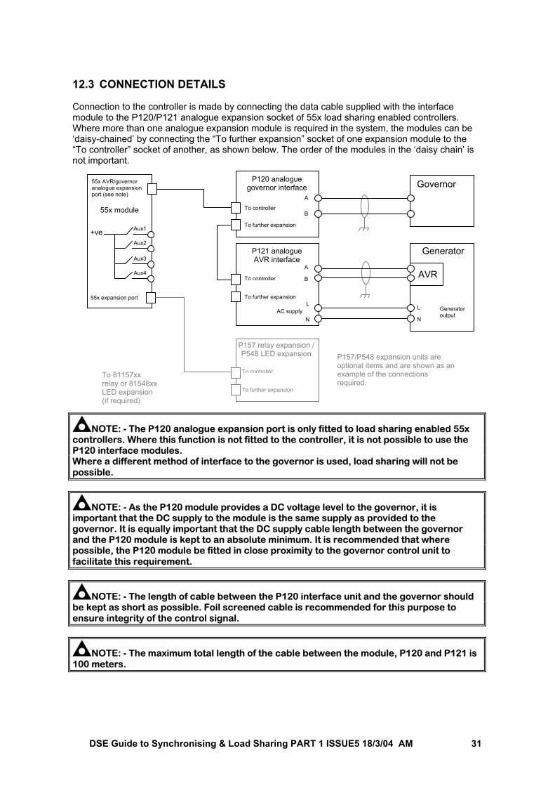
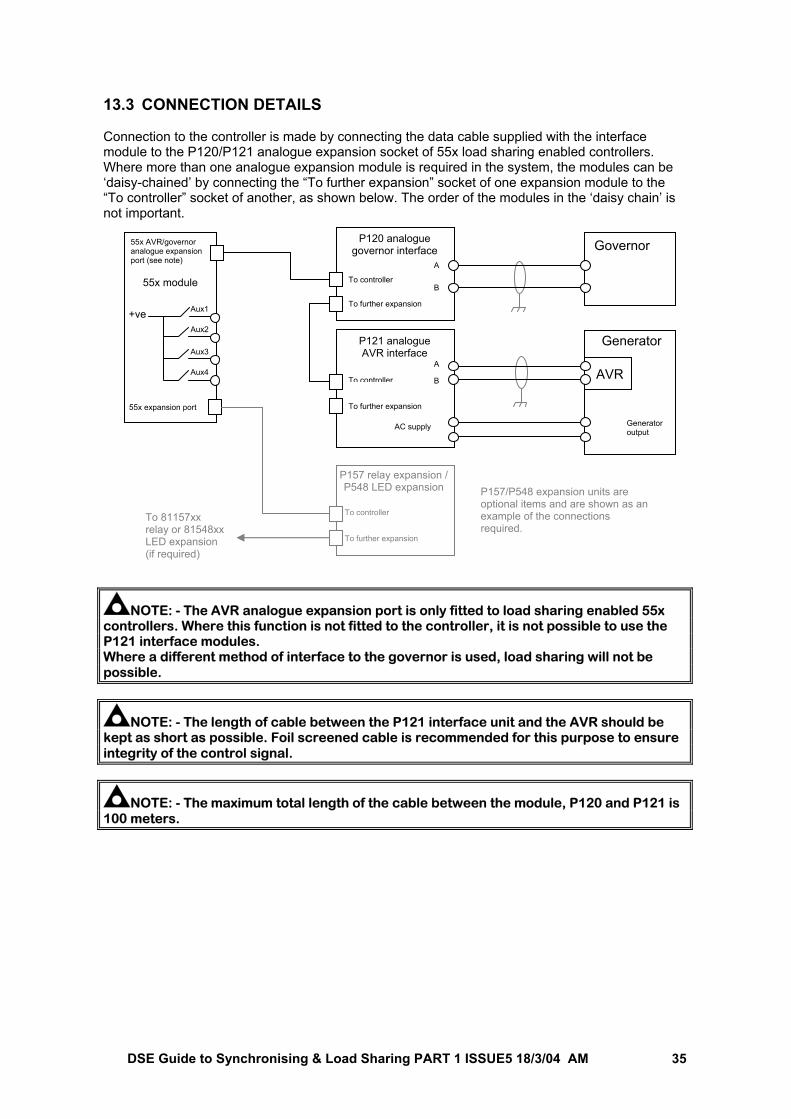
12.3 CONNECTION DETAILS Connection to the controller is made by connecting the data cable supplied with the interface module to the P120/P121 analogue expansion socket of 55x load sharing enabled controllers. Where more than one analogue expansion module is required in the system, the modules can be ‘daisy-chained’ by connecting the “To further expansion” socket of one expansion module to the “To controller” socket of another, as shown below. The order of the modules in the ‘daisy chain’ is not important.
NOTE: - The P120 analogue expansion port is only fitted to load sharing enabled 55x controllers. Where this function is not fitted to the controller, it is not possible to use the P120 interface modules. Where a different method of interface to the governor is used, load sharing will not be possible.
NOTE: - As the P120 module provides a DC voltage level to the governor, it is important that the DC supply to the module is the same supply as provided to the governor. It is equally important that the DC supply cable length between the governor and the P120 module is kept to an absolute minimum. It is recommended that where possible, the P120 module be fitted in close proximity to the governor control unit to facilitate this requirement.
NOTE: - The length of cable between the P120 interface unit and the governor should be kept as short as possible. Foil screened cable is recommended for this purpose to ensure integrity of the control signal.
NOTE: - The maximum total length of the cable between the module, P120 and P121 is 100 meters.
To controller
To further expansion
P157 relay expansion / P548 LED expansion
To 81157xx relay or 81548xx LED expansion (if required)
55x module
+ve Aux1
Aux2
Aux3
Aux4
55x expansion port
Governor
P120 analogue governor interface
To controller
To further expansion
P121 analogue AVR interface
To controller
To further expansion
AVR
55x AVR/governor analogue expansion port (see note)
Generator
AC supply Generator output
L
N
P157/P548 expansion units are optional items and are shown as an example of the connections required.
A
B
A
B
L
N
DSE Guide to Synchronising & Load Sharing PART 1 ISSUE5 18/3/04 AM 32
P120 SELECTOR SWITCH SETTINGS To enable the P120 analogue Governor interface modules to interface with as many different types of governor as possible, rotary selectors for voltage range and nominal voltage are fitted. These allow the user to configure the output of the module to match the input of the governor. 12.3.1 SW1 The SW1 selector sets the ‘centre’ point of the interface module’s output. For example: if the output range required is 1V to 3V, with the ‘centre’ point being at 2V, then the position of the SW1 selector would be 4, giving a voltage offset of 2V. 12.3.2 SW2 The SW2 selector sets the voltage output range of the interface module’s output. For example: if the output range required is 1V to 3V, then the position of the SW2 selector would be 1, giving a voltage range of ±1V from the ‘centre’ point of 2V 12.3.3 SW1 / SW2 SELECTOR SETTINGS. For reference purposes, the switch positions perform the following functions:
SW1 setting ‘centre’ voltage of P120
SW2 setting Voltage range of P120
0 0V 0 ±0.5V 1 0.5V 1 ±1.0V 2 1.0V 2 ±1.5V 3 1.5V 3 ±2.0V 4 2.0V 4 ±2.5V 5 2.5V 5 ±3.0V 6 3.0V 6 ±3.5V 7 3.5V 7 ±4.0V 8 4.0V 8 ±4.5V 9 4.5V 9 ±5.0V
Typical wiring diagrams for many of the most popular governors are included within this manual (See sections entitled Interfacing to Governors). Where these diagrams include the P120 interface module, the switch positions required for both SW1 and SW2 are given.
NOTE: - If the governor you are using is not listed within this manual, it may still be possible to interface to it using the P120 module. Contact your governor manufacturer to check if the product has a DC voltage input for connection to a synchroniser / load sharer, and if so, what the ‘voltage range’ and ‘centre voltage’ is. You can then use the tables above to determine settings for SW1 and SW2. P120 terminal A is the negative output terminal and B is the positive output terminal (providing governor output reversed is not selected in the 55x controller’s configuration). If the ‘centre voltage’ and ‘voltage range’ are not available from the governor manufacturer, providing the input is compatible with a DC voltage signal, it still may be possible to interface to it using the P120 modules. Contact our Technical Support Department for advice. If the governor is not fitted with a DC voltage input for connection to synchroniser/load share modules, then a different interface method will be required. See section entitled Interfacing to governors.
DSE Guide to Synchronising & Load Sharing PART 1 ISSUE5 18/3/04 AM 33
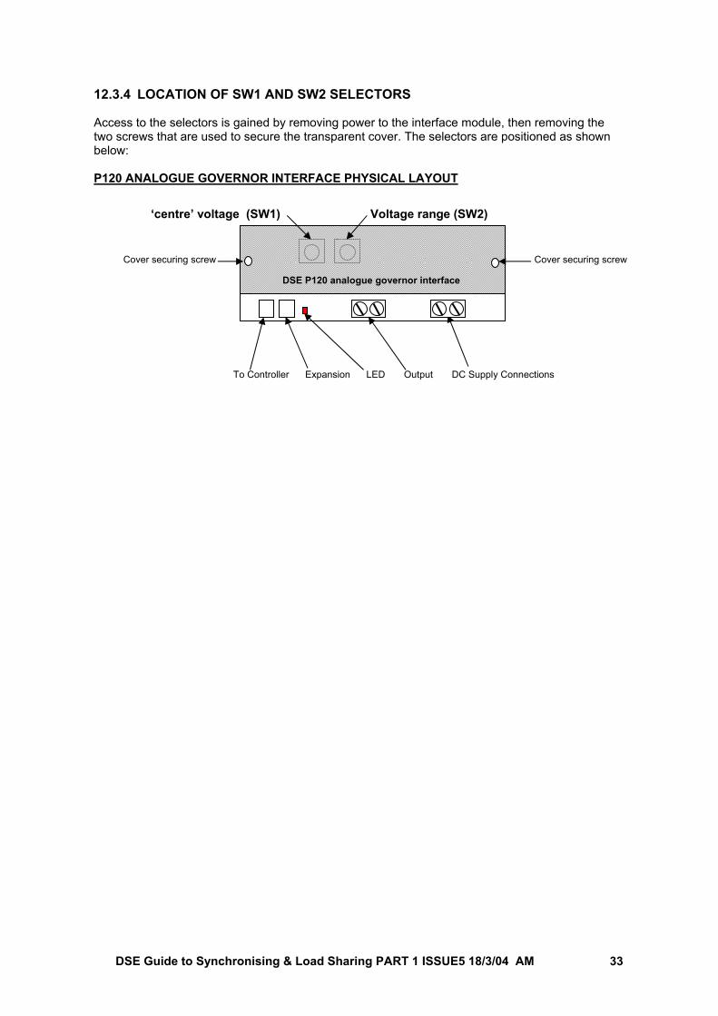
12.3.4 LOCATION OF SW1 AND SW2 SELECTORS Access to the selectors is gained by removing power to the interface module, then removing the two screws that are used to secure the transparent cover. The selectors are positioned as shown below: P120 ANALOGUE GOVERNOR INTERFACE PHYSICAL LAYOUT
‘centre’ voltage (SW1) Voltage range (SW2)
Cover securing screw
To Controller Expansion LED Output DC Supply Connections
DSE P120 analogue governor interface
Cover securing screw
DSE Guide to Synchronising & Load Sharing PART 1 ISSUE5 18/3/04 AM 34
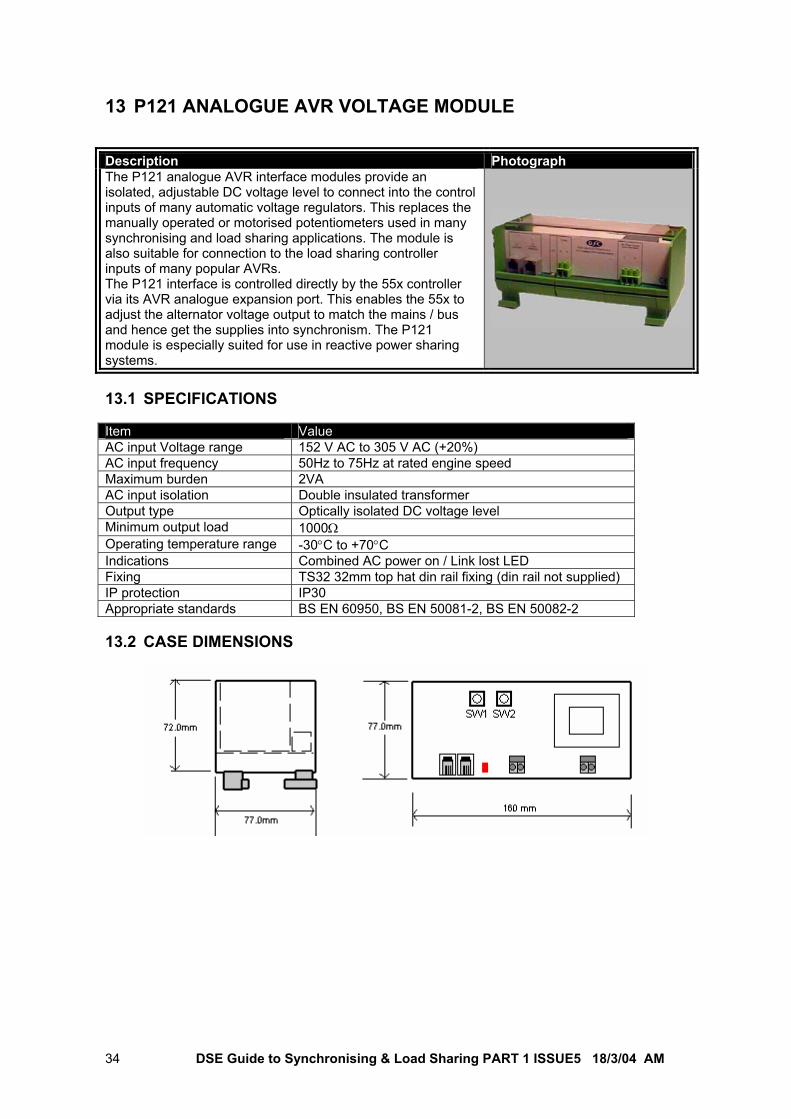
13 P121 ANALOGUE AVR VOLTAGE MODULE Description Photograph The P121 analogue AVR interface modules provide an isolated, adjustable DC voltage level to connect into the control inputs of many automatic voltage regulators. This replaces the manually operated or motorised potentiometers used in many synchronising and load sharing applications. The module is also suitable for connection to the load sharing controller inputs of many popular AVRs. The P121 interface is controlled directly by the 55x controller via its AVR analogue expansion port. This enables the 55x to adjust the alternator voltage output to match the mains / bus and hence get the supplies into synchronism. The P121 module is especially suited for use in reactive power sharing systems. 13.1 SPECIFICATIONS Item Value AC input Voltage range 152 V AC to 305 V AC (+20%) AC input frequency 50Hz to 75Hz at rated engine speed Maximum burden 2VA AC input isolation Double insulated transformer Output type Optically isolated DC voltage level Minimum output load 1000Ω Operating temperature range -30°C to +70°C Indications Combined AC power on / Link lost LED Fixing TS32 32mm top hat din rail fixing (din rail not supplied) IP protection IP30 Appropriate standards BS EN 60950, BS EN 50081-2, BS EN 50082-2 13.2 CASE DIMENSIONS
DSE Guide to Synchronising & Load Sharing PART 1 ISSUE5 18/3/04 AM 35
13.3 CONNECTION DETAILS Connection to the controller is made by connecting the data cable supplied with the interface module to the P120/P121 analogue expansion socket of 55x load sharing enabled controllers. Where more than one analogue expansion module is required in the system, the modules can be ‘daisy-chained’ by connecting the “To further expansion” socket of one expansion module to the “To controller” socket of another, as shown below. The order of the modules in the ‘daisy chain’ is not important.
NOTE: - The AVR analogue expansion port is only fitted to load sharing enabled 55x controllers. Where this function is not fitted to the controller, it is not possible to use the P121 interface modules. Where a different method of interface to the governor is used, load sharing will not be possible.
NOTE: - The length of cable between the P121 interface unit and the AVR should be kept as short as possible. Foil screened cable is recommended for this purpose to ensure integrity of the control signal.
NOTE: - The maximum total length of the cable between the module, P120 and P121 is 100 meters.
To controller
To further expansion
P157 relay expansion / P548 LED expansion
To 81157xx relay or 81548xx LED expansion (if required)
55x module
+ve Aux1
Aux2
Aux3
Aux4
55x expansion port
Governor
P120 analogue governor interface
To controller
To further expansion
P121 analogue AVR interface
To controller
To further expansion
AVR
55x AVR/governor analogue expansion port (see note)
Generator
AC supply Generator output
P157/P548 expansion units are optional items and are shown as an example of the connections required.
A
B
A
B
DSE Guide to Synchronising & Load Sharing PART 1 ISSUE5 18/3/04 AM 36
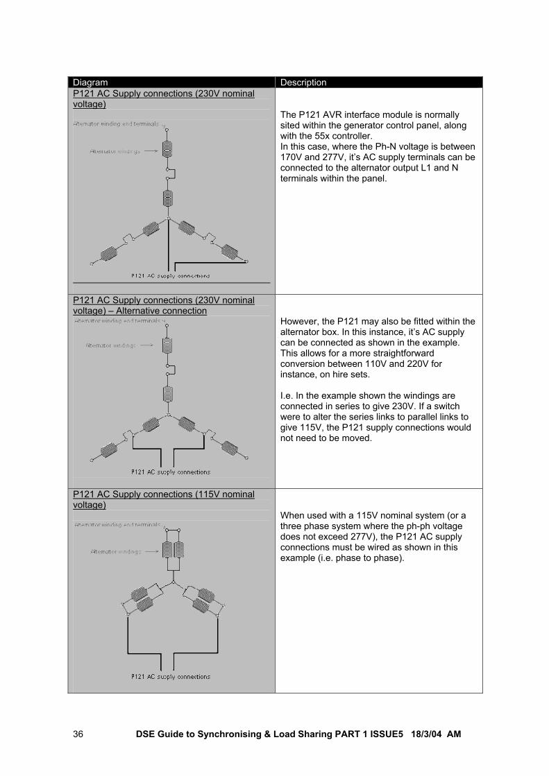
Diagram Description P121 AC Supply connections (230V nominal voltage)
The P121 AVR interface module is normally sited within the generator control panel, along with the 55x controller. In this case, where the Ph-N voltage is between 170V and 277V, it’s AC supply terminals can be connected to the alternator output L1 and N terminals within the panel.
P121 AC Supply connections (230V nominal voltage) – Alternative connection
However, the P121 may also be fitted within the alternator box. In this instance, it’s AC supply can be connected as shown in the example. This allows for a more straightforward conversion between 110V and 220V for instance, on hire sets. I.e. In the example shown the windings are connected in series to give 230V. If a switch were to alter the series links to parallel links to give 115V, the P121 supply connections would not need to be moved.
P121 AC Supply connections (115V nominal voltage)
When used with a 115V nominal system (or a three phase system where the ph-ph voltage does not exceed 277V), the P121 AC supply connections must be wired as shown in this example (i.e. phase to phase).
DSE Guide to Synchronising & Load Sharing PART 1 ISSUE5 18/3/04 AM 37
13.4 P121 SELECTOR SWITCH SETTINGS To enable the P121 analogue AVR interface module to interface with as many different types of AVR as possible, rotary selectors for voltage range and nominal voltage are fitted. These allow the user to configure the output of the module to match the input of the AVR. 13.4.1 SW1 The SW1 selector sets the ‘centre’ point of the interface module’s output. For example: if the output range required is 1V to 3V, with the ‘centre’ point being at 2V, then the position of the SW1 selector would be 4, giving a voltage offset of 2V. 13.4.2 SW2 The SW2 selector sets the voltage output range of the interface module’s output. For example: if the output range required is 1V to 3V, then the position of the SW2 selector would be 1, giving a voltage range of ±1V from the ‘centre’ point of 2V 13.4.3 SW1 / SW2 SELECTOR SETTINGS. For reference purposes, the switch positions perform the following functions: SW1 setting ‘centre’ voltage of P121 SW2 setting Voltage range of P121
0 0V 0 ±0.5V 1 0.5V 1 ±1.0V 2 1.0V 2 ±1.5V 3 1.5V 3 ±2.0V 4 2.0V 4 ±2.5V 5 2.5V 5 ±3.0V 6 3.0V 6 ±3.5V 7 3.5V 7 ±4.0V 8 4.0V 8 ±4.5V 9 4.5V 9 ±5.0V
Typical wiring diagrams for many of the most popular AVRs are included within this manual (See section entitled Interfacing to AVRs). Where these diagrams include the P121 interface modules, the switch positions required for both SW1 and SW2 are given.
NOTE: - If the AVR you are using is not listed within this manual, it may still be possible to interface to it using the P121 modules. Contact your AVR manufacturer to check if the product has a DC voltage input for connection to a synchroniser / load sharer, and if so, what the ‘voltage range’ and ‘centre voltage’ is. You can then use the tables above to determine settings for SW1 and SW2. P121 terminal A is the negative output terminal and B is the positive output terminal (providing governor output reversed is not selected in the 55x controller’s configuration). If the ‘centre voltage’ and ‘voltage range’ are not available from the AVR manufacturer, providing the input is compatible with a DC voltage signal, it still may be possible to interface to it using the P121 modules. Contact our Technical Support Department for advice. If the AVR is not fitted with a DC voltage input for connection to synchroniser/load share modules, then a different interface method will be required. See section entitled Interfacing to AVRs.
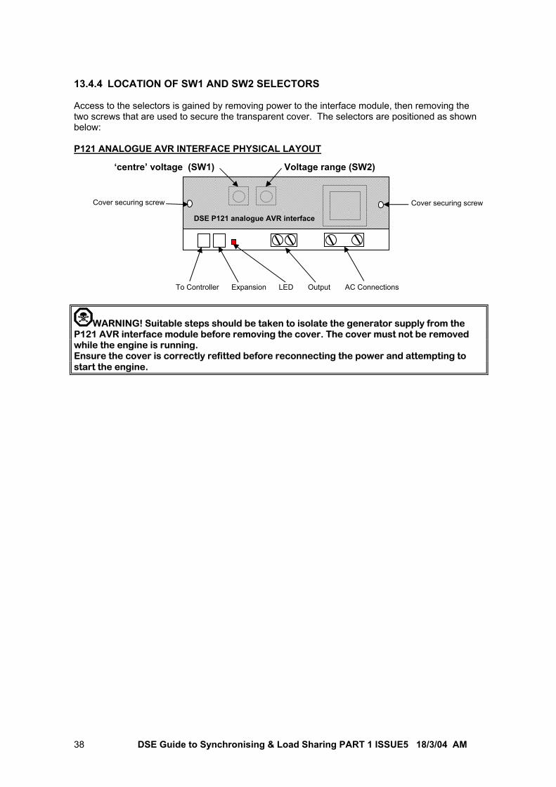
DSE Guide to Synchronising & Load Sharing PART 1 ISSUE5 18/3/04 AM 38
13.4.4 LOCATION OF SW1 AND SW2 SELECTORS Access to the selectors is gained by removing power to the interface module, then removing the two screws that are used to secure the transparent cover. The selectors are positioned as shown below: P121 ANALOGUE AVR INTERFACE PHYSICAL LAYOUT
WARNING! Suitable steps should be taken to isolate the generator supply from the P121 AVR interface module before removing the cover. The cover must not be removed while the engine is running. Ensure the cover is correctly refitted before reconnecting the power and attempting to start the engine.
‘centre’ voltage (SW1) Voltage range (SW2)
Cover securing screw
DSE P121 analogue AVR interface
Cover securing screw
To Controller Expansion LED Output AC Connections
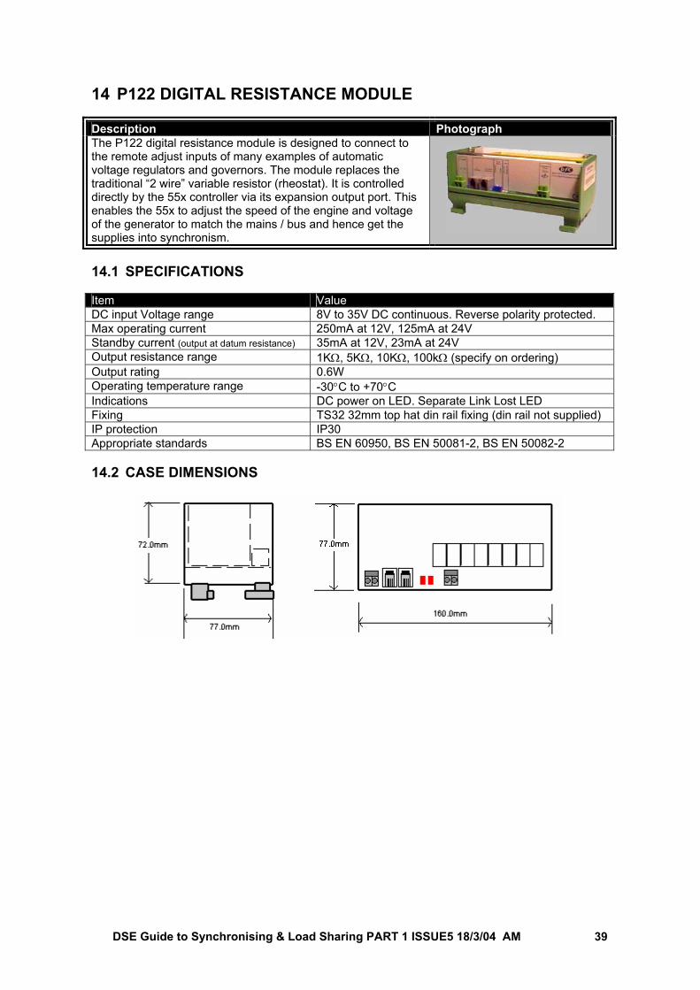
DSE Guide to Synchronising & Load Sharing PART 1 ISSUE5 18/3/04 AM 39
14 P122 DIGITAL RESISTANCE MODULE Description Photograph The P122 digital resistance module is designed to connect to the remote adjust inputs of many examples of automatic voltage regulators and governors. The module replaces the traditional “2 wire” variable resistor (rheostat). It is controlled directly by the 55x controller via its expansion output port. This enables the 55x to adjust the speed of the engine and voltage of the generator to match the mains / bus and hence get the supplies into synchronism.
14.1 SPECIFICATIONS Item Value DC input Voltage range 8V to 35V DC continuous. Reverse polarity protected. Max operating current 250mA at 12V, 125mA at 24V Standby current (output at datum resistance) 35mA at 12V, 23mA at 24V Output resistance range 1KΩ, 5KΩ, 10KΩ, 100kΩ (specify on ordering) Output rating 0.6W Operating temperature range -30°C to +70°C Indications DC power on LED. Separate Link Lost LED Fixing TS32 32mm top hat din rail fixing (din rail not supplied) IP protection IP30 Appropriate standards BS EN 60950, BS EN 50081-2, BS EN 50082-2 14.2 CASE DIMENSIONS
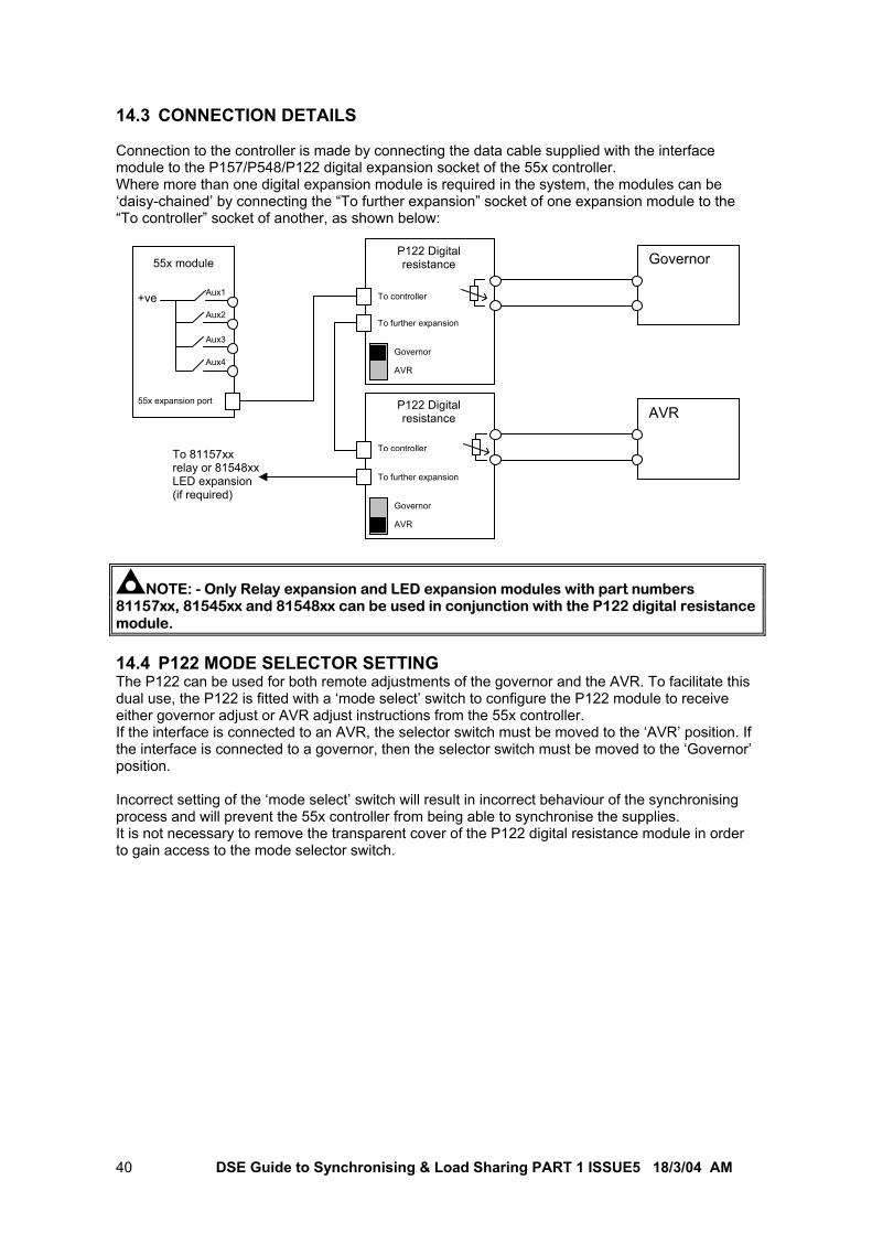
DSE Guide to Synchronising & Load Sharing PART 1 ISSUE5 18/3/04 AM 40
14.3 CONNECTION DETAILS Connection to the controller is made by connecting the data cable supplied with the interface module to the P157/P548/P122 digital expansion socket of the 55x controller. Where more than one digital expansion module is required in the system, the modules can be ‘daisy-chained’ by connecting the “To further expansion” socket of one expansion module to the “To controller” socket of another, as shown below:
NOTE: - Only Relay expansion and LED expansion modules with part numbers 81157xx, 81545xx and 81548xx can be used in conjunction with the P122 digital resistance module. 14.4 P122 MODE SELECTOR SETTING The P122 can be used for both remote adjustments of the governor and the AVR. To facilitate this dual use, the P122 is fitted with a ‘mode select’ switch to configure the P122 module to receive either governor adjust or AVR adjust instructions from the 55x controller. If the interface is connected to an AVR, the selector switch must be moved to the ‘AVR’ position. If the interface is connected to a governor, then the selector switch must be moved to the ‘Governor’ position. Incorrect setting of the ‘mode select’ switch will result in incorrect behaviour of the synchronising process and will prevent the 55x controller from being able to synchronise the supplies. It is not necessary to remove the transparent cover of the P122 digital resistance module in order to gain access to the mode selector switch.
55x module
+ve Aux1
Aux2
Aux3
Aux4
55x expansion port
Governor
P122 Digital resistance
To controller
To further expansion
AVR
Governor
P122 Digital resistance
To controller
To further expansion
AVR
Governor
AVR
To 81157xx relay or 81548xx LED expansion (if required)
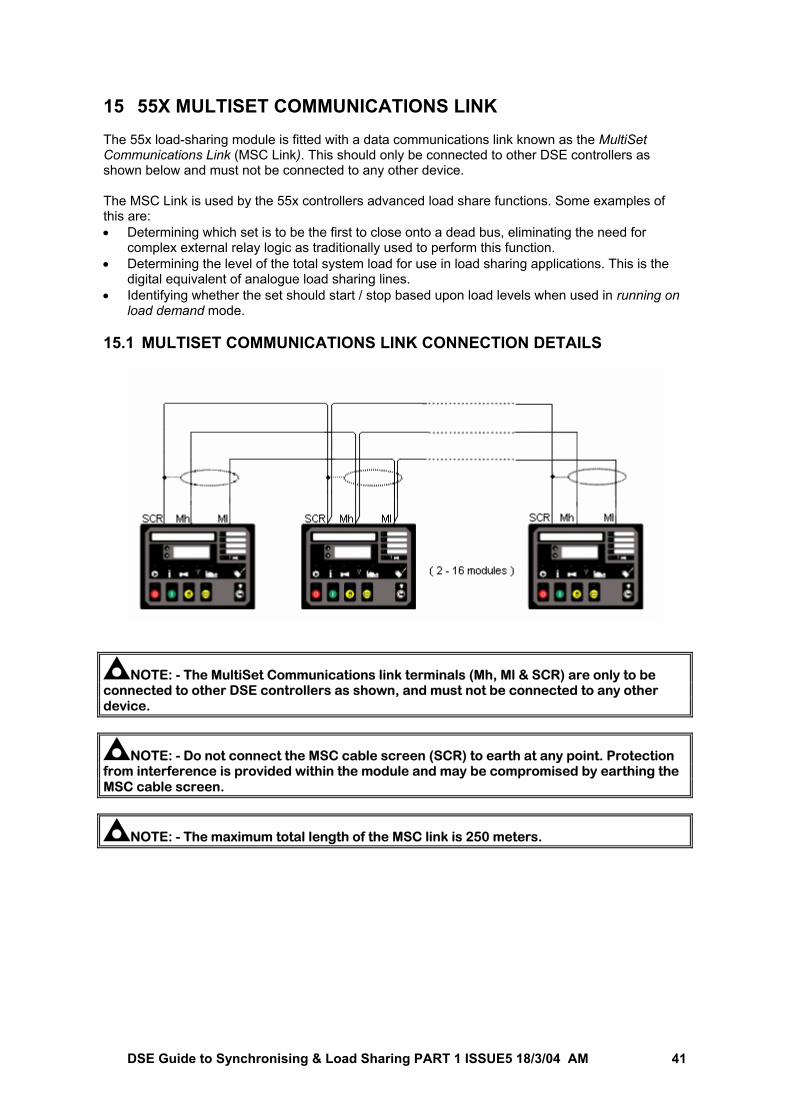
DSE Guide to Synchronising & Load Sharing PART 1 ISSUE5 18/3/04 AM 41
15 55X MULTISET COMMUNICATIONS LINK The 55x load-sharing module is fitted with a data communications link known as the MultiSet Communications Link (MSC Link). This should only be connected to other DSE controllers as shown below and must not be connected to any other device. The MSC Link is used by the 55x controllers advanced load share functions. Some examples of this are: • Determining which set is to be the first to close onto a dead bus, eliminating the need for
complex external relay logic as traditionally used to perform this function. • Determining the level of the total system load for use in load sharing applications. This is the
digital equivalent of analogue load sharing lines. • Identifying whether the set should start / stop based upon load levels when used in running on
load demand mode. 15.1 MULTISET COMMUNICATIONS LINK CONNECTION DETAILS
NOTE: - The MultiSet Communications link terminals (Mh, Ml & SCR) are only to be connected to other DSE controllers as shown, and must not be connected to any other device.
NOTE: - Do not connect the MSC cable screen (SCR) to earth at any point. Protection from interference is provided within the module and may be compromised by earthing the MSC cable screen.
NOTE: - The maximum total length of the MSC link is 250 meters.
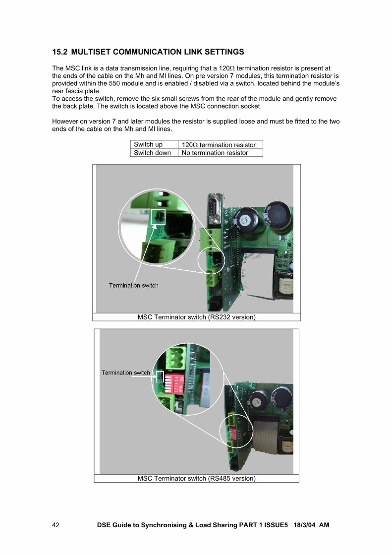
DSE Guide to Synchronising & Load Sharing PART 1 ISSUE5 18/3/04 AM 42
15.2 MULTISET COMMUNICATION LINK SETTINGS The MSC link is a data transmission line, requiring that a 120Ω termination resistor is present at the ends of the cable on the Mh and Ml lines. On pre version 7 modules, this termination resistor is provided within the 550 module and is enabled / disabled via a switch, located behind the module’s rear fascia plate. To access the switch, remove the six small screws from the rear of the module and gently remove the back plate. The switch is located above the MSC connection socket. However on version 7 and later modules the resistor is supplied loose and must be fitted to the two ends of the cable on the Mh and Ml lines.
Switch up 120Ω termination resistor Switch down No termination resistor
MSC Terminator switch (RS232 version)
MSC Terminator switch (RS485 version)
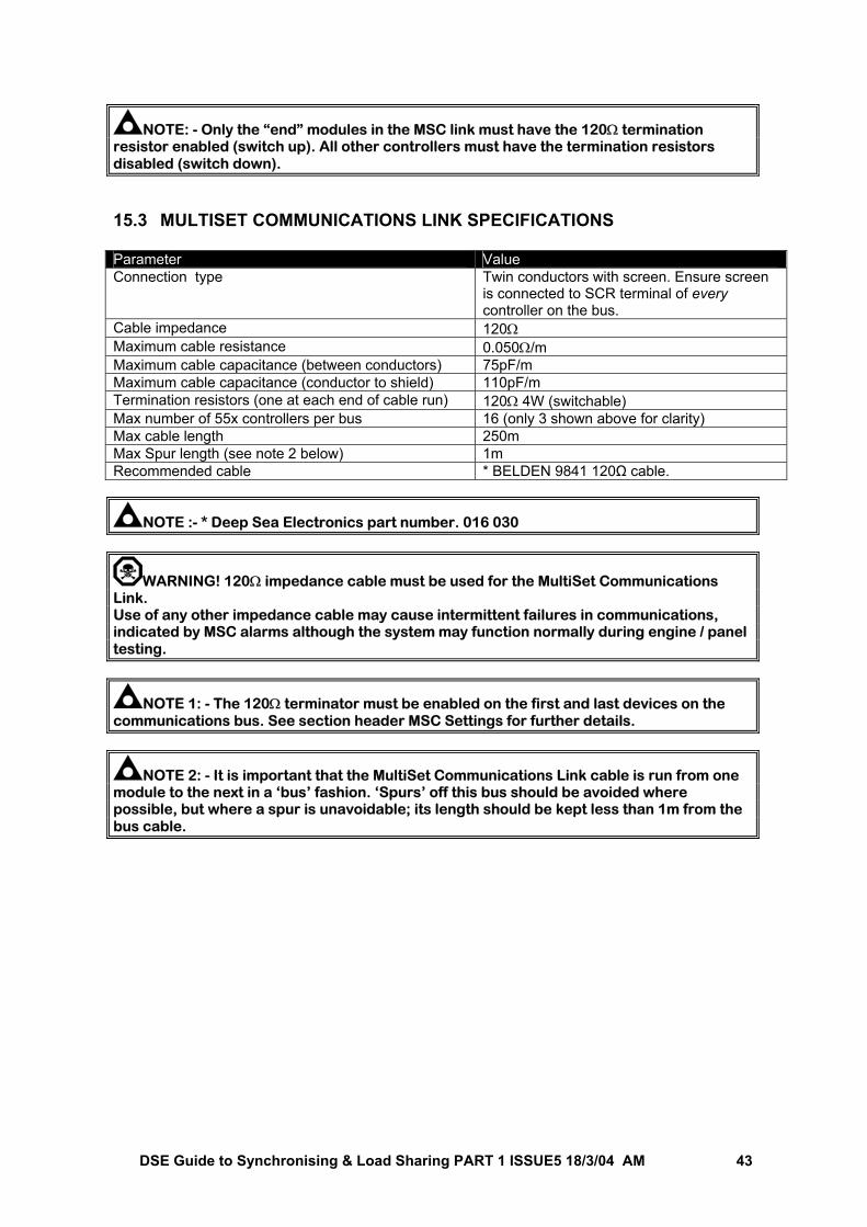
DSE Guide to Synchronising & Load Sharing PART 1 ISSUE5 18/3/04 AM 43
NOTE: - Only the “end” modules in the MSC link must have the 120Ω termination resistor enabled (switch up). All other controllers must have the termination resistors disabled (switch down). 15.3 MULTISET COMMUNICATIONS LINK SPECIFICATIONS Parameter Value Connection type Twin conductors with screen. Ensure screen
is connected to SCR terminal of every controller on the bus.
Cable impedance 120Ω Maximum cable resistance 0.050Ω/m Maximum cable capacitance (between conductors) 75pF/m Maximum cable capacitance (conductor to shield) 110pF/m Termination resistors (one at each end of cable run) 120Ω 4W (switchable) Max number of 55x controllers per bus 16 (only 3 shown above for clarity) Max cable length 250m Max Spur length (see note 2 below) 1m Recommended cable * BELDEN 9841 120Ω cable.
NOTE :- * Deep Sea Electronics part number. 016 030
WARNING! 120Ω impedance cable must be used for the MultiSet Communications Link. Use of any other impedance cable may cause intermittent failures in communications, indicated by MSC alarms although the system may function normally during engine / panel testing.
NOTE 1: - The 120Ω terminator must be enabled on the first and last devices on the communications bus. See section header MSC Settings for further details.
NOTE 2: - It is important that the MultiSet Communications Link cable is run from one module to the next in a ‘bus’ fashion. ‘Spurs’ off this bus should be avoided where possible, but where a spur is unavoidable; its length should be kept less than 1m from the bus cable.
DSE Guide to Synchronising & Load Sharing PART 1 ISSUE5 18/3/04 AM 44
15.4 MULTISET COMMUNICATIONS LINK ALARMS Several alarms are provided to warn the operator of possible problems with the communication link between the gensets. 15.4.1 MSC ID ALARM Each genset must have a unique MSC ID so that they can properly communicate. Should two or more sets have the same ID then one or more of the affected sets will declare “MSC ID ERROR” this will cause an electrical trip on the affected set. The correct ID must be set using the P810 software.
NOTE: - To avoid possible problems with spare modules it is suggested that units are commissioned in the system starting with ID 1 and then 2,3… etc. Any modules used as spares should be configured as number 16,15… etc. These can then be added to the system without causing any conflicts with existing modules. Alternatively, use the P810 for Windows™ configuration software to reconfigure the module to suit. 15.4.2 MSC DATA ERROR When the sets are communicating on the MultiSet Communications link, should the data be corrupted the affected modules will display ‘MSC DATA ERROR’. This will cause an electrical trip on the affected set.
CAUTION! - Care should be taken to ensure that correct wiring is used between the modules, the MSC terminator is correctly enabled on only end units on the link and that maximum cable run distances are not exceeded. Should data error alarms be apparent, operation of the MultiSet system may not be possible. 15.4.3 MSC FAILURE If the number of modules communicating on the Multset communications link should fall, then an MSC failure alarm will occur. This can be configured to a ‘warning’ or ‘electrical trip’ type alarm. Should the number of modules on the communications link fall below the “Minimum modules on Multiset comms link” configurable setting, an additional alarm is triggered. This alarm can be disabled, or configured to generate a warning or electrical trip alarm. If the number of modules communicating on the Multset communications link should rise, then any existing ‘MSC failure’ warning alarm is cleared, and all communicating modules are automatically reconfigured to ‘expect’ the increased number of sets on the bus. Additionally, one of the module’s digital inputs can be configured so that the MSC failure alarm is disabled when the input is active. The module can be configured to alert / remind the user of this via an indication or warning alarm if required via the “Multiset comms alarm disabled action” setting.
NOTE:- For details on the MSC failure alarm settings, you are referred to the section entitled “5xx controller configuration for load sharing” elsewhere in this manual.
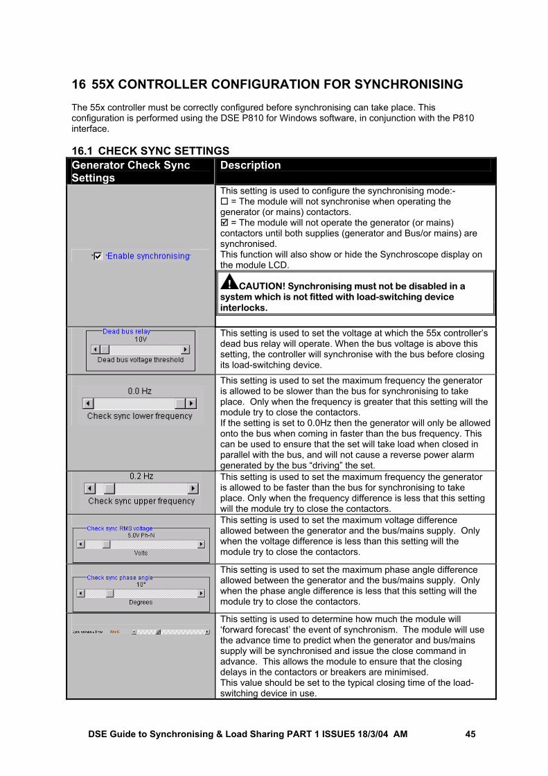
DSE Guide to Synchronising & Load Sharing PART 1 ISSUE5 18/3/04 AM 45
16 55X CONTROLLER CONFIGURATION FOR SYNCHRONISING The 55x controller must be correctly configured before synchronising can take place. This configuration is performed using the DSE P810 for Windows software, in conjunction with the P810 interface. 16.1 CHECK SYNC SETTINGS Generator Check Sync Settings
Description
This setting is used to configure the synchronising mode:- = The module will not synchronise when operating the
generator (or mains) contactors. = The module will not operate the generator (or mains)
contactors until both supplies (generator and Bus/or mains) are synchronised. This function will also show or hide the Synchroscope display on the module LCD.
CAUTION! Synchronising must not be disabled in a system which is not fitted with load-switching device interlocks.
This setting is used to set the voltage at which the 55x controller’s dead bus relay will operate. When the bus voltage is above this setting, the controller will synchronise with the bus before closing its load-switching device.
This setting is used to set the maximum frequency the generator is allowed to be slower than the bus for synchronising to take place. Only when the frequency is greater that this setting will the module try to close the contactors. If the setting is set to 0.0Hz then the generator will only be allowed onto the bus when coming in faster than the bus frequency. This can be used to ensure that the set will take load when closed in parallel with the bus, and will not cause a reverse power alarm generated by the bus “driving” the set.
This setting is used to set the maximum frequency the generator is allowed to be faster than the bus for synchronising to take place. Only when the frequency difference is less that this setting will the module try to close the contactors.
This setting is used to set the maximum voltage difference allowed between the generator and the bus/mains supply. Only when the voltage difference is less than this setting will the module try to close the contactors.
This setting is used to set the maximum phase angle difference allowed between the generator and the bus/mains supply. Only when the phase angle difference is less that this setting will the module try to close the contactors.
This setting is used to determine how much the module will ‘forward forecast’ the event of synchronism. The module will use the advance time to predict when the generator and bus/mains supply will be synchronised and issue the close command in advance. This allows the module to ensure that the closing delays in the contactors or breakers are minimised. This value should be set to the typical closing time of the load-switching device in use.
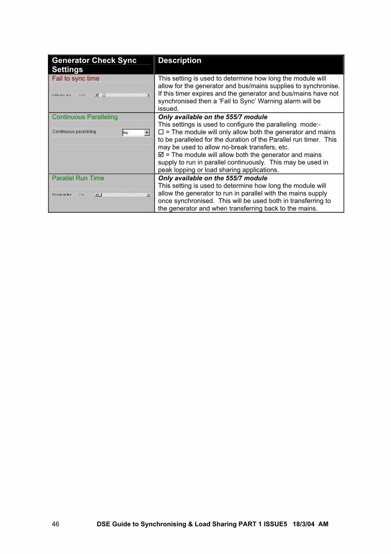
DSE Guide to Synchronising & Load Sharing PART 1 ISSUE5 18/3/04 AM 46
Generator Check Sync Settings
Description
Fail to sync time
This setting is used to determine how long the module will allow for the generator and bus/mains supplies to synchronise. If this timer expires and the generator and bus/mains have not synchronised then a ‘Fail to Sync’ Warning alarm will be issued.
Continuous Paralleling
Only available on the 555/7 module This settings is used to configure the paralleling mode:-
= The module will only allow both the generator and mains to be paralleled for the duration of the Parallel run timer. This may be used to allow no-break transfers, etc.
= The module will allow both the generator and mains supply to run in parallel continuously. This may be used in peak lopping or load sharing applications.
Parallel Run Time
Only available on the 555/7 module This setting is used to determine how long the module will allow the generator to run in parallel with the mains supply once synchronised. This will be used both in transferring to the generator and when transferring back to the mains.
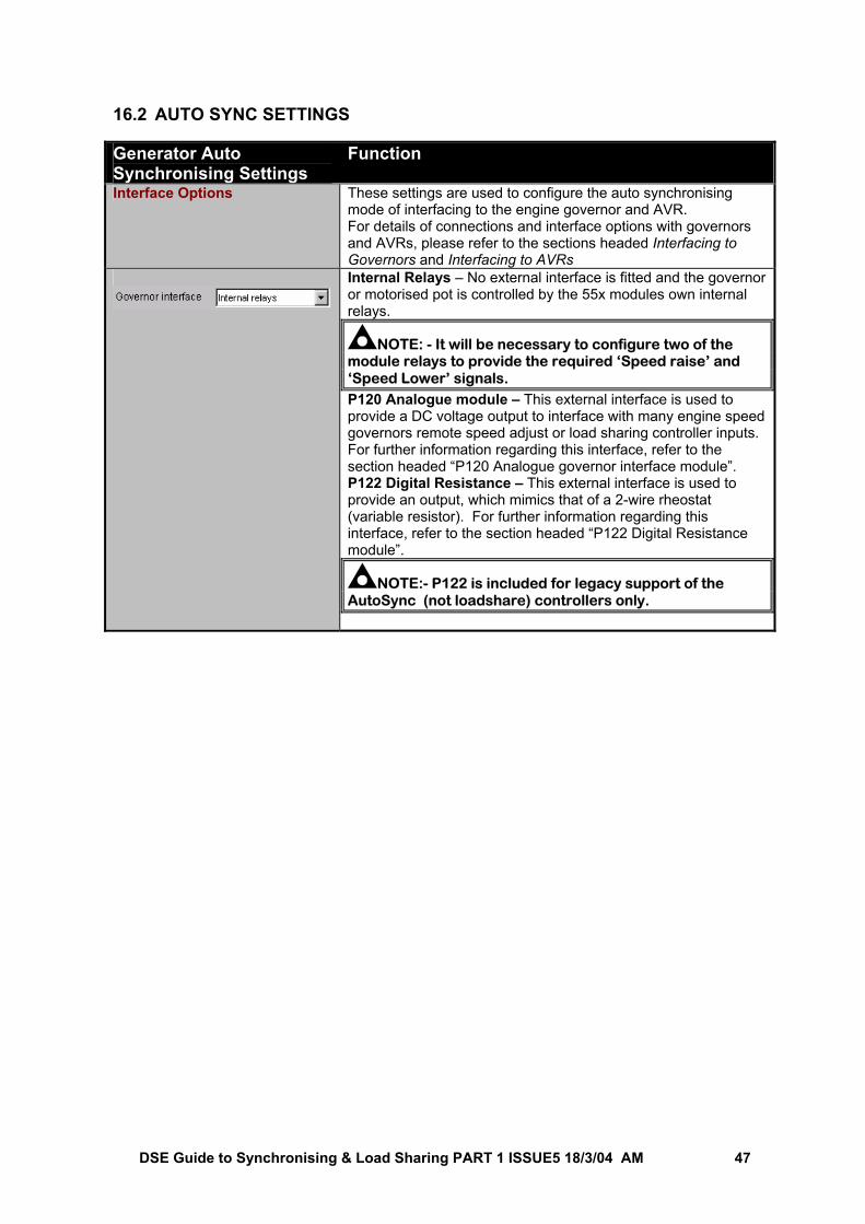
DSE Guide to Synchronising & Load Sharing PART 1 ISSUE5 18/3/04 AM 47
16.2 AUTO SYNC SETTINGS Generator Auto Synchronising Settings
Function
Interface Options These settings are used to configure the auto synchronising mode of interfacing to the engine governor and AVR. For details of connections and interface options with governors and AVRs, please refer to the sections headed Interfacing to Governors and Interfacing to AVRs
Internal Relays – No external interface is fitted and the governor or motorised pot is controlled by the 55x modules own internal relays.
NOTE: - It will be necessary to configure two of the module relays to provide the required ‘Speed raise’ and ‘Speed Lower’ signals. P120 Analogue module – This external interface is used to provide a DC voltage output to interface with many engine speed governors remote speed adjust or load sharing controller inputs. For further information regarding this interface, refer to the section headed “P120 Analogue governor interface module”. P122 Digital Resistance – This external interface is used to provide an output, which mimics that of a 2-wire rheostat (variable resistor). For further information regarding this interface, refer to the section headed “P122 Digital Resistance module”.
NOTE:- P122 is included for legacy support of the AutoSync (not loadshare) controllers only.
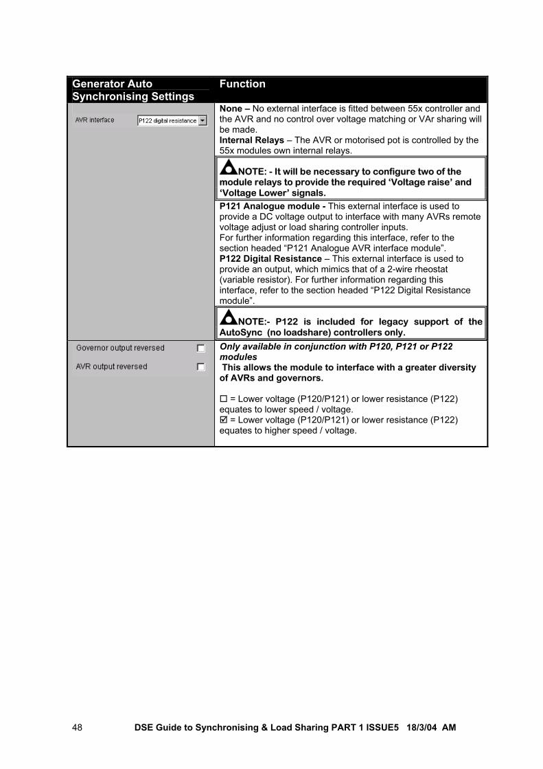
DSE Guide to Synchronising & Load Sharing PART 1 ISSUE5 18/3/04 AM 48
Generator Auto Synchronising Settings
Function
None – No external interface is fitted between 55x controller and the AVR and no control over voltage matching or VAr sharing will be made. Internal Relays – The AVR or motorised pot is controlled by the 55x modules own internal relays.
NOTE: - It will be necessary to configure two of the module relays to provide the required ‘Voltage raise’ and ‘Voltage Lower’ signals. P121 Analogue module - This external interface is used to provide a DC voltage output to interface with many AVRs remote voltage adjust or load sharing controller inputs. For further information regarding this interface, refer to the section headed “P121 Analogue AVR interface module”. P122 Digital Resistance – This external interface is used to provide an output, which mimics that of a 2-wire rheostat (variable resistor). For further information regarding this interface, refer to the section headed “P122 Digital Resistance module”.
NOTE:- P122 is included for legacy support of the AutoSync (no loadshare) controllers only.
Only available in conjunction with P120, P121 or P122 modules This allows the module to interface with a greater diversity of AVRs and governors.
= Lower voltage (P120/P121) or lower resistance (P122) equates to lower speed / voltage.
= Lower voltage (P120/P121) or lower resistance (P122) equates to higher speed / voltage.
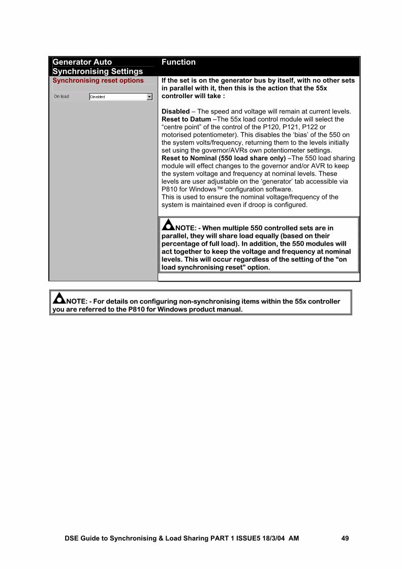
DSE Guide to Synchronising & Load Sharing PART 1 ISSUE5 18/3/04 AM 49
Generator Auto Synchronising Settings
Function
Synchronising reset options
If the set is on the generator bus by itself, with no other sets in parallel with it, then this is the action that the 55x controller will take : Disabled – The speed and voltage will remain at current levels. Reset to Datum –The 55x load control module will select the “centre point” of the control of the P120, P121, P122 or motorised potentiometer). This disables the ‘bias’ of the 550 on the system volts/frequency, returning them to the levels initially set using the governor/AVRs own potentiometer settings. Reset to Nominal (550 load share only) –The 550 load sharing module will effect changes to the governor and/or AVR to keep the system voltage and frequency at nominal levels. These levels are user adjustable on the ‘generator’ tab accessible via P810 for Windows™ configuration software. This is used to ensure the nominal voltage/frequency of the system is maintained even if droop is configured.
NOTE: - When multiple 550 controlled sets are in parallel, they will share load equally (based on their percentage of full load). In addition, the 550 modules will act together to keep the voltage and frequency at nominal levels. This will occur regardless of the setting of the “on load synchronising reset” option.
NOTE: - For details on configuring non-synchronising items within the 55x controller you are referred to the P810 for Windows product manual.
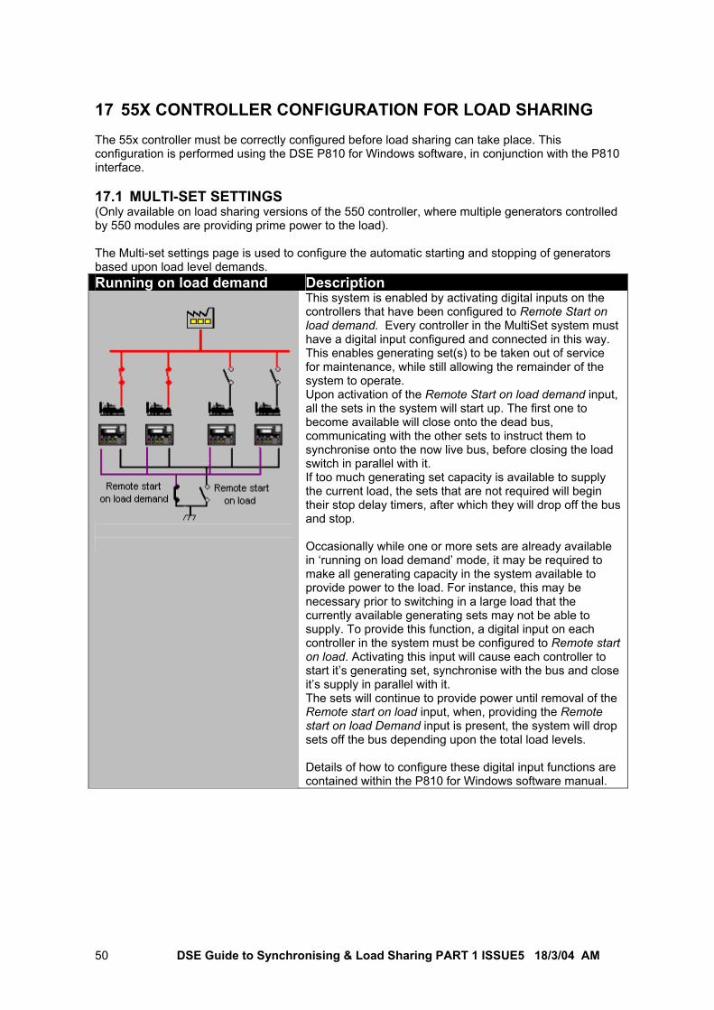
DSE Guide to Synchronising & Load Sharing PART 1 ISSUE5 18/3/04 AM 50
17 55X CONTROLLER CONFIGURATION FOR LOAD SHARING The 55x controller must be correctly configured before load sharing can take place. This configuration is performed using the DSE P810 for Windows software, in conjunction with the P810 interface. 17.1 MULTI-SET SETTINGS (Only available on load sharing versions of the 550 controller, where multiple generators controlled by 550 modules are providing prime power to the load). The Multi-set settings page is used to configure the automatic starting and stopping of generators based upon load level demands. Running on load demand Description
This system is enabled by activating digital inputs on the controllers that have been configured to Remote Start on load demand. Every controller in the MultiSet system must have a digital input configured and connected in this way. This enables generating set(s) to be taken out of service for maintenance, while still allowing the remainder of the system to operate. Upon activation of the Remote Start on load demand input, all the sets in the system will start up. The first one to become available will close onto the dead bus, communicating with the other sets to instruct them to synchronise onto the now live bus, before closing the load switch in parallel with it. If too much generating set capacity is available to supply the current load, the sets that are not required will begin their stop delay timers, after which they will drop off the bus and stop. Occasionally while one or more sets are already available in ‘running on load demand’ mode, it may be required to make all generating capacity in the system available to provide power to the load. For instance, this may be necessary prior to switching in a large load that the currently available generating sets may not be able to supply. To provide this function, a digital input on each controller in the system must be configured to Remote start on load. Activating this input will cause each controller to start it’s generating set, synchronise with the bus and close it’s supply in parallel with it. The sets will continue to provide power until removal of the Remote start on load input, when, providing the Remote start on load Demand input is present, the system will drop sets off the bus depending upon the total load levels. Details of how to configure these digital input functions are contained within the P810 for Windows software manual.
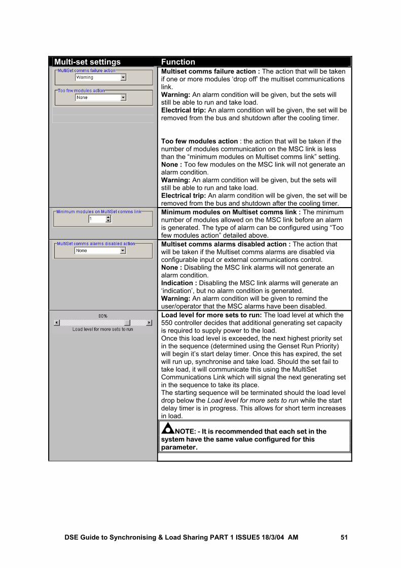
DSE Guide to Synchronising & Load Sharing PART 1 ISSUE5 18/3/04 AM 51
Multi-set settings Function
Multiset comms failure action : The action that will be taken if one or more modules ‘drop off’ the multiset communications link. Warning: An alarm condition will be given, but the sets will still be able to run and take load. Electrical trip: An alarm condition will be given, the set will be removed from the bus and shutdown after the cooling timer. Too few modules action : the action that will be taken if the number of modules communication on the MSC link is less than the “minimum modules on Multiset comms link” setting. None : Too few modules on the MSC link will not generate an alarm condition. Warning: An alarm condition will be given, but the sets will still be able to run and take load. Electrical trip: An alarm condition will be given, the set will be removed from the bus and shutdown after the cooling timer.
Minimum modules on Multiset comms link : The minimum number of modules allowed on the MSC link before an alarm is generated. The type of alarm can be configured using “Too few modules action” detailed above.
Multiset comms alarms disabled action : The action that will be taken if the Multiset comms alarms are disabled via configurable input or external communications control. None : Disabling the MSC link alarms will not generate an alarm condition. Indication : Disabling the MSC link alarms will generate an ‘indication’, but no alarm condition is generated. Warning: An alarm condition will be given to remind the user/operator that the MSC alarms have been disabled.
Load level for more sets to run: The load level at which the 550 controller decides that additional generating set capacity is required to supply power to the load. Once this load level is exceeded, the next highest priority set in the sequence (determined using the Genset Run Priority) will begin it’s start delay timer. Once this has expired, the set will run up, synchronise and take load. Should the set fail to take load, it will communicate this using the MultiSet Communications Link which will signal the next generating set in the sequence to take its place. The starting sequence will be terminated should the load level drop below the Load level for more sets to run while the start delay timer is in progress. This allows for short term increases in load.
NOTE: - It is recommended that each set in the system have the same value configured for this parameter.
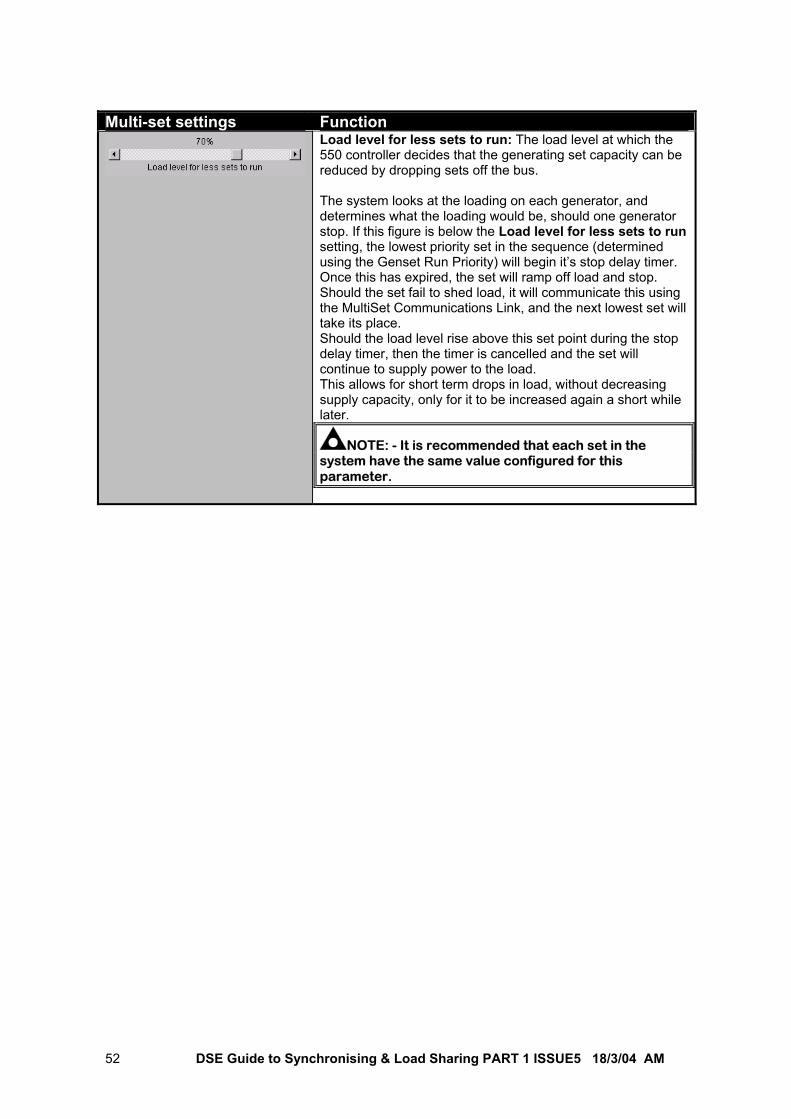
DSE Guide to Synchronising & Load Sharing PART 1 ISSUE5 18/3/04 AM 52
Multi-set settings Function
Load level for less sets to run: The load level at which the 550 controller decides that the generating set capacity can be reduced by dropping sets off the bus. The system looks at the loading on each generator, and determines what the loading would be, should one generator stop. If this figure is below the Load level for less sets to run setting, the lowest priority set in the sequence (determined using the Genset Run Priority) will begin it’s stop delay timer. Once this has expired, the set will ramp off load and stop. Should the set fail to shed load, it will communicate this using the MultiSet Communications Link, and the next lowest set will take its place. Should the load level rise above this set point during the stop delay timer, then the timer is cancelled and the set will continue to supply power to the load. This allows for short term drops in load, without decreasing supply capacity, only for it to be increased again a short while later.
NOTE: - It is recommended that each set in the system have the same value configured for this parameter.
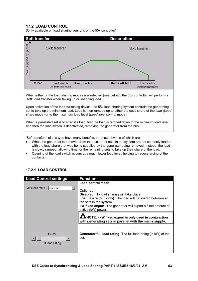
DSE Guide to Synchronising & Load Sharing PART 1 ISSUE5 18/3/04 AM 53
17.2 LOAD CONTROL (Only available on load sharing versions of the 55x controller) Soft transfer Description
When either of the load sharing modes are selected (see below), the 55x controller will perform a ‘soft’ load transfer when taking up or shedding load. Upon activation of the load-switching device, the 55x load sharing system controls the generating set to take up the minimum load. Load is then ramped up to either the set’s share of the load (Load share mode) or to the maximum load level (Load level control mode). When a paralleled set is to shed it’s load, first the load is ramped down to the minimum load level, and then the load switch is deactivated, removing the generator from the bus. ‘Soft transfers’ of this type have many benefits, the most obvious of which are: • When the generator is removed from the bus, other sets in the system are not suddenly loaded
with the load share that was being supplied by the generator being removed. Instead, the load is slowly ramped, allowing time for the remaining sets to take up their share of the load.
• Opening of the load switch occurs at a much lower load level, helping to reduce arcing of the contacts.
17.2.1 LOAD CONTROL Load Control settings Function
Load control mode Options : Disabled: No load sharing will take place. Load Share (550 only): The load will be shared between all the sets in the system. kW fixed export: The generator will export a fixed amount of active (kW) power.
NOTE: - kW fixed export is only used in conjunction with generating sets in parallel with the mains supply.
Generator full load rating: The full load rating (in kW) of the set.
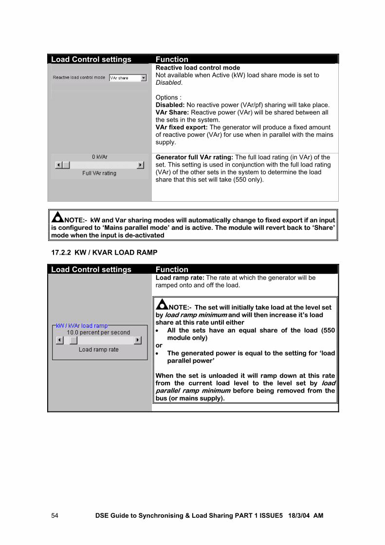
DSE Guide to Synchronising & Load Sharing PART 1 ISSUE5 18/3/04 AM 54
Load Control settings Function
Reactive load control mode Not available when Active (kW) load share mode is set to Disabled. Options : Disabled: No reactive power (VAr/pf) sharing will take place. VAr Share: Reactive power (VAr) will be shared between all the sets in the system. VAr fixed export: The generator will produce a fixed amount of reactive power (VAr) for use when in parallel with the mains supply.
Generator full VAr rating: The full load rating (in VAr) of the set. This setting is used in conjunction with the full load rating (VAr) of the other sets in the system to determine the load share that this set will take (550 only).
NOTE:- kW and Var sharing modes will automatically change to fixed export if an input is configured to ‘Mains parallel mode’ and is active. The module will revert back to ‘Share’ mode when the input is de-activated 17.2.2 KW / KVAR LOAD RAMP Load Control settings Function
Load ramp rate: The rate at which the generator will be ramped onto and off the load.
NOTE:- The set will initially take load at the level set by load ramp minimum and will then increase it’s load share at this rate until either • All the sets have an equal share of the load (550
module only) or • The generated power is equal to the setting for ‘load
parallel power’ When the set is unloaded it will ramp down at this rate from the current load level to the level set by load parallel ramp minimum before being removed from the bus (or mains supply).
DSE Guide to Synchronising & Load Sharing PART 1 ISSUE5 18/3/04 AM 55
18 ON SITE COMMISSIONING 18.1 DISABLING REMOTE ADJUSTMENT OF THE GOVERNOR / AVR During commissioning, the remote adjust signals to the governor and AVR must be disabled to ensure that the only method of adjustment is the governor/AVRs main internal adjustment. The method of disabling this signal depends upon the method of interface between the 55x controller and the governor / AVR: 18.1.1 RAISE/LOWER INPUTS When using the 55x controllers internal raise/lower outputs to remotely adjust speed / voltage, they must be disabled by one of the two following methods: a) Utilise the P810 configuration software to set the 55x auxiliary outputs to “unused” (taking care
to make a backup copy of the module’s configuration before doing this). b) Remove the connections to the 55x controllers raise/lower outputs (taking care to correctly
insulate the removed wire ends). 18.1.2 P120 ANALOGUE GOVERNOR INTERFACE MODULE When using a P120 analogue governor interface module to control the governor, this interface module must be partially disabled. To do this, remove the data connection cable from the “From Controller” socket. After three seconds, the P120’s LED will begin to flash. This indicates loss of data communication with the 55x controller, and the P120 will automatically select its centre point, removing any controlling signal from the governor’s speed bias input.
NOTE: - The DC supply must be correctly connected to the P120 module when performing this operation. 18.1.3 P121 ANALOGUE AVR INTERFACE MODULE When using a P121 analogue AVR interface module to control the AVR, this interface module must be partially disabled. To do this, remove the data connection cable from the “From Controller” socket. When the generator begins producing electricity and supplies power to the P121 module, the P121’s LED will begin to flash. This indicates loss of data communication with the 55x controller, and the P121 will automatically select its centre point, removing any controlling signal from the AVRs voltage bias input.
NOTE: - The AC supply must be correctly connected to the P121 module when performing this operation.
NOTE: - The Link Lost LED will be extinguished until the generator begins to supply voltage to the ‘AC supply’ terminals of the P121 module. 18.1.4 P122 DIGITAL RESISTANCE MODULE When using a P122 digital resistance module to control the governor/AVR, this interface module must be partially disabled. To do this, remove the data connection cable from the P122s “From Controller” socket. The P122’s POWER LED will remain lit, but after three seconds the LINK LOST LED will begin to flash. This indicates loss of data communication with the 55x controller, and the P122 will automatically select its centre point, removing any controlling signal from the AVRs/Governors voltage/speed bias input.
NOTE: - The DC supply must be correctly connected to the P122 module when performing this operation.
DSE Guide to Synchronising & Load Sharing PART 1 ISSUE5 18/3/04 AM 56
18.1.5 ELECTRONIC / MOTORISED POTENTIOMETERS When using an electronic or motorised potentiometer to remotely adjust the speed / voltage, this must be disabled before adjusting the governor/AVRs datum point. The method of disabling varies between different equipment manufacturers. You should refer to the documentation provided with your electronic / motorised potentiometer for details of how to achieve this. 18.2 SETTING GOVERNOR SPEED AND AVR VOLTAGE Once the remote adjustments have been disabled, the AVR and governor commissioning instructions can be followed to set their datum point (speed and voltage with no load and no external adjustments). After this has been performed and correctly verified, the remote adjustment connections can be re-enabled by reversing the instructions previously followed.
NOTE: - When setting the off load speed and voltage, use the 55x’s built in instrumentation to verify the settings. Adjusting voltage to an accuracy of ±1V and frequency to an accuracy of ±0.1Hz between the different sets will ease the process of setting up the load sharing parameters later.
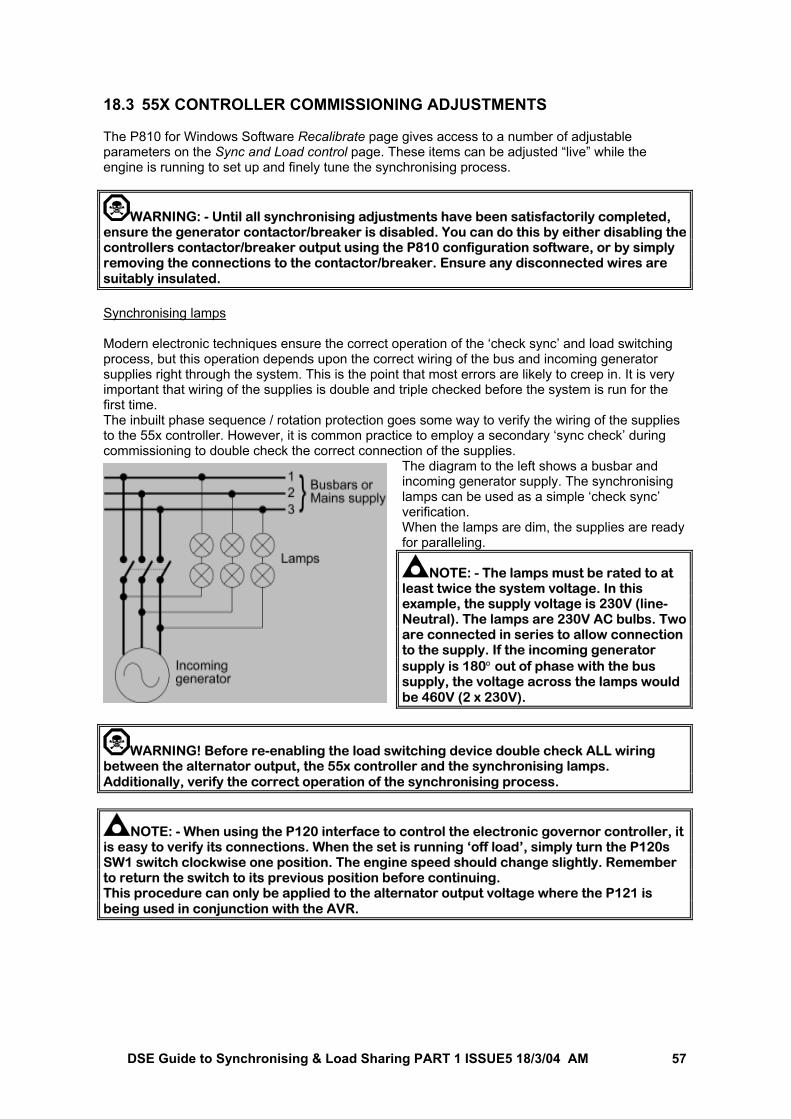
DSE Guide to Synchronising & Load Sharing PART 1 ISSUE5 18/3/04 AM 57
18.3 55X CONTROLLER COMMISSIONING ADJUSTMENTS The P810 for Windows Software Recalibrate page gives access to a number of adjustable parameters on the Sync and Load control page. These items can be adjusted “live” while the engine is running to set up and finely tune the synchronising process.
WARNING: - Until all synchronising adjustments have been satisfactorily completed, ensure the generator contactor/breaker is disabled. You can do this by either disabling the controllers contactor/breaker output using the P810 configuration software, or by simply removing the connections to the contactor/breaker. Ensure any disconnected wires are suitably insulated. Synchronising lamps Modern electronic techniques ensure the correct operation of the ‘check sync’ and load switching process, but this operation depends upon the correct wiring of the bus and incoming generator supplies right through the system. This is the point that most errors are likely to creep in. It is very important that wiring of the supplies is double and triple checked before the system is run for the first time. The inbuilt phase sequence / rotation protection goes some way to verify the wiring of the supplies to the 55x controller. However, it is common practice to employ a secondary ‘sync check’ during commissioning to double check the correct connection of the supplies.
The diagram to the left shows a busbar and incoming generator supply. The synchronising lamps can be used as a simple ‘check sync’ verification. When the lamps are dim, the supplies are ready for paralleling.
NOTE: - The lamps must be rated to at least twice the system voltage. In this example, the supply voltage is 230V (line-Neutral). The lamps are 230V AC bulbs. Two are connected in series to allow connection to the supply. If the incoming generator supply is 180° out of phase with the bus supply, the voltage across the lamps would be 460V (2 x 230V).
WARNING! Before re-enabling the load switching device double check ALL wiring between the alternator output, the 55x controller and the synchronising lamps. Additionally, verify the correct operation of the synchronising process.
NOTE: - When using the P120 interface to control the electronic governor controller, it is easy to verify its connections. When the set is running ‘off load’, simply turn the P120s SW1 switch clockwise one position. The engine speed should change slightly. Remember to return the switch to its previous position before continuing. This procedure can only be applied to the alternator output voltage where the P121 is being used in conjunction with the AVR.
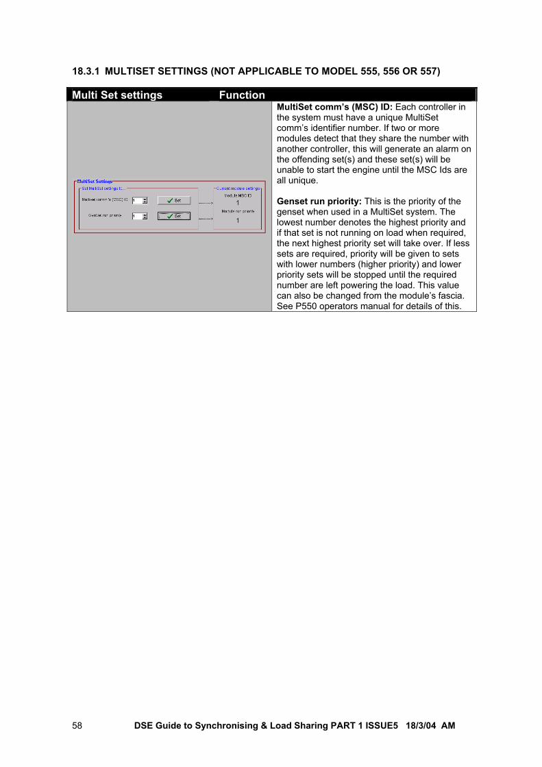
DSE Guide to Synchronising & Load Sharing PART 1 ISSUE5 18/3/04 AM 58
18.3.1 MULTISET SETTINGS (NOT APPLICABLE TO MODEL 555, 556 OR 557) Multi Set settings Function
MultiSet comm’s (MSC) ID: Each controller in the system must have a unique MultiSet comm’s identifier number. If two or more modules detect that they share the number with another controller, this will generate an alarm on the offending set(s) and these set(s) will be unable to start the engine until the MSC Ids are all unique. Genset run priority: This is the priority of the genset when used in a MultiSet system. The lowest number denotes the highest priority and if that set is not running on load when required, the next highest priority set will take over. If less sets are required, priority will be given to sets with lower numbers (higher priority) and lower priority sets will be stopped until the required number are left powering the load. This value can also be changed from the module’s fascia. See P550 operators manual for details of this.
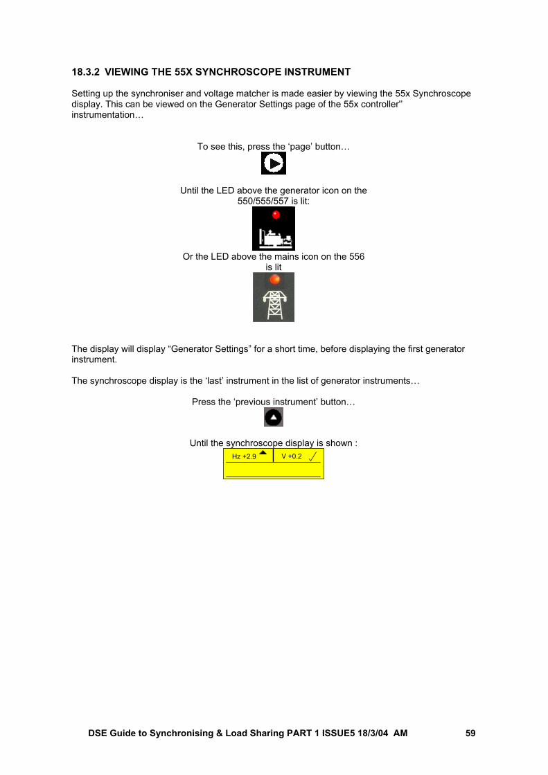
DSE Guide to Synchronising & Load Sharing PART 1 ISSUE5 18/3/04 AM 59
18.3.2 VIEWING THE 55X SYNCHROSCOPE INSTRUMENT Setting up the synchroniser and voltage matcher is made easier by viewing the 55x Synchroscope display. This can be viewed on the Generator Settings page of the 55x controller'’ instrumentation…
To see this, press the ‘page’ button…
Until the LED above the generator icon on the 550/555/557 is lit:
Or the LED above the mains icon on the 556
is lit
The display will display “Generator Settings” for a short time, before displaying the first generator instrument. The synchroscope display is the ‘last’ instrument in the list of generator instruments…
Press the ‘previous instrument’ button…
Until the synchroscope display is shown : Hz +2.9 V +0.2
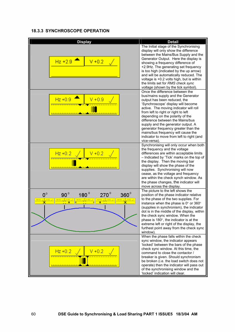
DSE Guide to Synchronising & Load Sharing PART 1 ISSUE5 18/3/04 AM 60
18.3.3 SYNCHROSCOPE OPERATION
Display Detail
The Initial stage of the Synchronising display will only show the difference between the Mains/Bus Supply and the Generator Output. Here the display is showing a frequency difference of +2.9Hz. The generating set frequency is too high (indicated by the up arrow) and will be automatically reduced. The voltage is +0.2 volts high, but is within the limits set for RMS check sync voltage (shown by the tick symbol).
Once the difference between the bus/mains supply and the Generator output has been reduced, the ‘Synchroscope’ display will become active. The moving indicator will roll from left to right or right to left depending on the polarity of the difference between the Mains/bus supply and the generator output. A generator frequency greater than the mains/bus frequency will cause the indicator to move from left to right (and vice-versa).
Synchronising will only occur when both the frequency and the voltage differences are within acceptable limits – Indicated by ‘Tick’ marks on the top of the display. Then the moving bar display will show the phase of the supplies. Synchronising will now cease, as the voltage and frequency are within the check synch window. As the phase changes, the indicator will move across the display. The picture to the left shows the position of the phase indicator relative to the phase of the two supplies. For instance when the phase is 0° or 360° (supplies in synchronism), the indicator dot is in the middle of the display, within the check sync window. When the phase is 180°, the indicator is at the extreme left or right of the display, the furthest point away from the check sync window).
When the phase falls within the check sync window, the indicator appears ‘locked’ between the bars of the phase check sync window. At this time, the command to close the contactor / breaker is given. Should synchronism be broken (i.e. the load switch does not operate) then the indicator will pass out of the synchronising window and the ‘locked’ indication will clear.
DSE Guide to Synchronising & Load Sharing PART 1 ISSUE5 18/3/04 AM 61
18.3.4 FREQUENCY SYNCHRONISER SETUP
WARNING: - Until all synchronising adjustments have been satisfactorily completed, ensure the generator contactor/breaker is disabled. You can do this by either disabling the controllers contactor/breaker output using the P810 configuration software, or by simply removing the connections to the contactor/breaker. Ensure any disconnected wires are suitably insulated. The method of setting up the 55x synchroniser depends upon the interface method between the 55x controller and the AVR/Governor. If your interface method uses the internal 55x raise/lower relays or the P122 digital resistance module, then you will use the ‘pulse’ scheme. If your interface method uses the P120 / P121 analogue interface module, then you will use the ‘analogue’ scheme.
NOTE: - There are four possible combinations of interface method: 1) P122 module (or internal raise/lower relays) to interface to governor and AVR (both
using the ‘pulse scheme’) 2) P122 module (or internal raise/lower speed relays) to interface to governor (‘pulse’
scheme) and P121 module to interface to AVR (‘analogue’ scheme). 3) P120 module to interface to governor (‘analogue’ scheme) and P122 module (or
internal raise/lower voltage relays) to interface to AVR. 4) P120 module to interface to governor and P121 module to interface to AVR (both using
the ‘analogue scheme’)
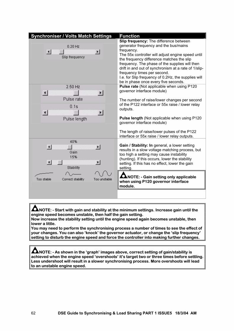
DSE Guide to Synchronising & Load Sharing PART 1 ISSUE5 18/3/04 AM 62
Synchroniser / Volts Match Settings Function
Slip frequency: The difference between generator frequency and the bus/mains frequency. The 55x controller will adjust engine speed until the frequency difference matches the slip frequency. The phase of the supplies will then drift in and out of synchronism at a rate of 1/slip-frequency times per second. I.e. for Slip frequency of 0.2Hz, the supplies will be in phase once every five seconds.
Pulse rate (Not applicable when using P120 governor interface module) The number of raise/lower changes per second of the P122 interface or 55x raise / lower relay outputs. Pulse length (Not applicable when using P120 governor interface module) The length of raise/lower pulses of the P122 interface or 55x raise / lower relay outputs.
Gain / Stability: In general, a lower setting results in a slow voltage matching process, but too high a setting may cause instability (hunting). If this occurs, lower the stability setting. If this has no effect, lower the gain setting.
NOTE: - Gain setting only applicable when using P120 governor interface module.
NOTE: - Start with gain and stability at the minimum settings. Increase gain until the engine speed becomes unstable, then half the gain setting. Now increase the stability setting until the engine speed again becomes unstable, then lower a little. You may need to perform the synchronising process a number of times to see the effect of your changes. You can also ‘knock’ the governor actuator, or change the ‘slip frequency’ setting to disturb the engine speed and force the controller into making further changes.
NOTE: - As shown in the ‘graph’ images above, correct setting of gain/stability is achieved when the engine speed ‘overshoots’ it’s target two or three times before settling. Less undershoot will result in a slower synchronising process. More overshoots will lead to an unstable engine speed.
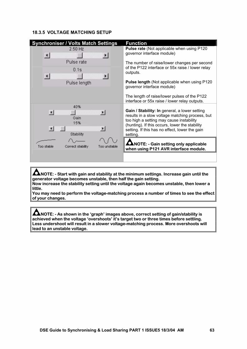
DSE Guide to Synchronising & Load Sharing PART 1 ISSUE5 18/3/04 AM 63
18.3.5 VOLTAGE MATCHING SETUP Synchroniser / Volts Match Settings Function
Pulse rate (Not applicable when using P120 governor interface module) The number of raise/lower changes per second of the P122 interface or 55x raise / lower relay outputs. Pulse length (Not applicable when using P120 governor interface module) The length of raise/lower pulses of the P122 interface or 55x raise / lower relay outputs.
Gain / Stability: In general, a lower setting results in a slow voltage matching process, but too high a setting may cause instability (hunting). If this occurs, lower the stability setting. If this has no effect, lower the gain setting.
NOTE: - Gain setting only applicable when using P121 AVR interface module.
NOTE: - Start with gain and stability at the minimum settings. Increase gain until the generator voltage becomes unstable, then half the gain setting. Now increase the stability setting until the voltage again becomes unstable, then lower a little. You may need to perform the voltage-matching process a number of times to see the effect of your changes.
NOTE: - As shown in the ‘graph’ images above, correct setting of gain/stability is achieved when the voltage ‘overshoots’ it’s target two or three times before settling. Less undershoot will result in a slower voltage-matching process. More overshoots will lead to an unstable voltage.
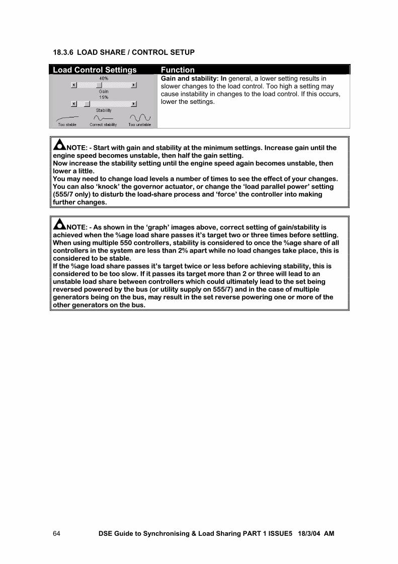
DSE Guide to Synchronising & Load Sharing PART 1 ISSUE5 18/3/04 AM 64
18.3.6 LOAD SHARE / CONTROL SETUP Load Control Settings Function
Gain and stability: In general, a lower setting results in slower changes to the load control. Too high a setting may cause instability in changes to the load control. If this occurs, lower the settings.
NOTE: - Start with gain and stability at the minimum settings. Increase gain until the engine speed becomes unstable, then half the gain setting. Now increase the stability setting until the engine speed again becomes unstable, then lower a little. You may need to change load levels a number of times to see the effect of your changes. You can also ‘knock’ the governor actuator, or change the ‘load parallel power’ setting (555/7 only) to disturb the load-share process and ‘force’ the controller into making further changes.
NOTE: - As shown in the ‘graph’ images above, correct setting of gain/stability is achieved when the %age load share passes it’s target two or three times before settling. When using multiple 550 controllers, stability is considered to once the %age share of all controllers in the system are less than 2% apart while no load changes take place, this is considered to be stable. If the %age load share passes it’s target twice or less before achieving stability, this is considered to be too slow. If it passes its target more than 2 or three will lead to an unstable load share between controllers which could ultimately lead to the set being reversed powered by the bus (or utility supply on 555/7) and in the case of multiple generators being on the bus, may result in the set reverse powering one or more of the other generators on the bus.
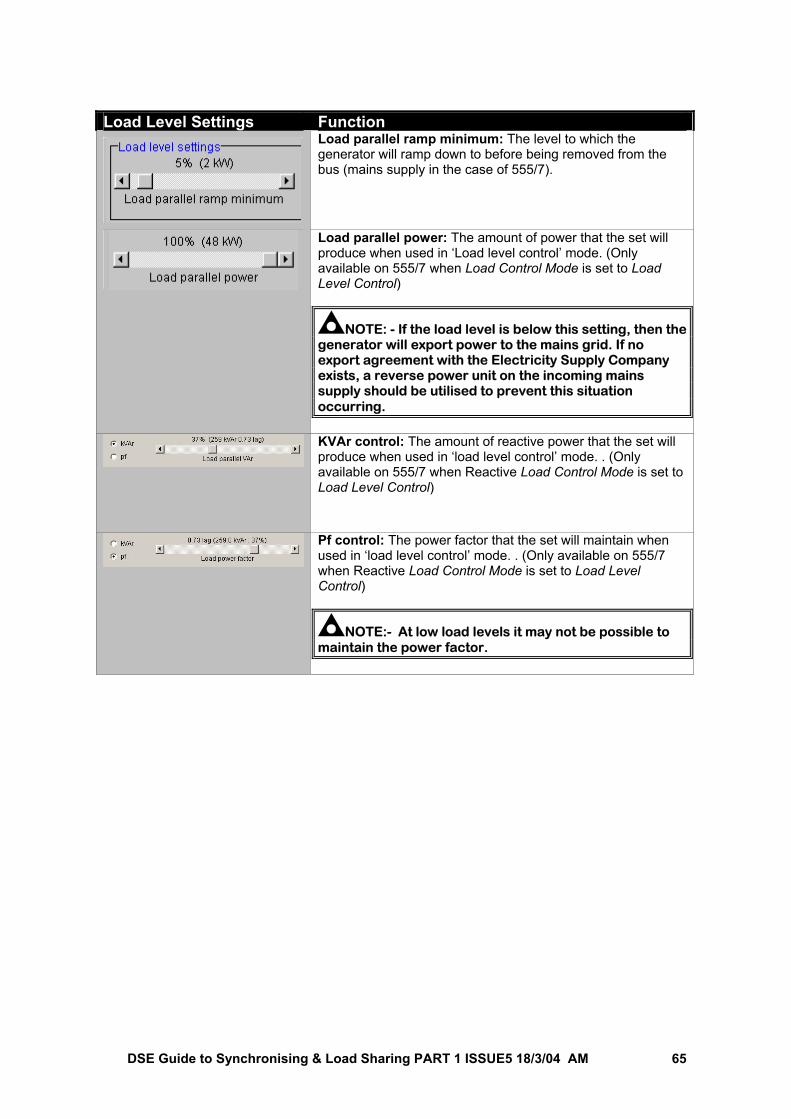
DSE Guide to Synchronising & Load Sharing PART 1 ISSUE5 18/3/04 AM 65
Load Level Settings Function
Load parallel ramp minimum: The level to which the generator will ramp down to before being removed from the bus (mains supply in the case of 555/7).
Load parallel power: The amount of power that the set will produce when used in ‘Load level control’ mode. (Only available on 555/7 when Load Control Mode is set to Load Level Control)
NOTE: - If the load level is below this setting, then the generator will export power to the mains grid. If no export agreement with the Electricity Supply Company exists, a reverse power unit on the incoming mains supply should be utilised to prevent this situation occurring.
KVAr control: The amount of reactive power that the set will produce when used in ‘load level control’ mode. . (Only available on 555/7 when Reactive Load Control Mode is set to Load Level Control)
Pf control: The power factor that the set will maintain when used in ‘load level control’ mode. . (Only available on 555/7 when Reactive Load Control Mode is set to Load Level Control)
NOTE:- At low load levels it may not be possible to maintain the power factor.
DSE Guide to Synchronising & Load Sharing PART 1 ISSUE5 18/3/04 AM 66
18.3.7 MAKING REACTIVE POWER SHARING ADJUSTMENTS (550 MULTISET WITH NO AVR CONTROL)
In this situation, as reactive power sharing is controlled purely by the generator’s AVR, it is the AVR voltage setting that must be adjusted to make any changes to the kVAr (reactive power) share. Example: With two sets in parallel, and one generator is supplying more VAr than the other. The voltage setting of the AVRs must be adjusted slightly to transfer the share from one generator to the other. Increasing the setting on one AVR has the effect of increasing that set’s share of the reactive power, and decreasing the other set(s) share of reactive power. As this will have slightly altered the generators output voltage, it should be checked to ensure that it has not been altered by too much. This procedure may have to be conducted more than once, possibly adjusting the other AVR(s) a little the following times to ensure a suitable reactive load share between the sets, while maintaining a suitable off load generator voltage.
NOTE: - Many AVRs have only a single turn potentiometer for adjusting the output voltage. This has the effect of making reactive power sharing adjustments very sensitive. Care should be taken to make small changes to the adjustment, and to ensure that the voltage / VAr is stable (i.e. not changing) before further changes are made.
NOTE: - Ensure the “Check voltage” window is suitably set to allow voltages to match even when the generator(s) already on the bus are loaded. Remember that a loaded generator with an AVR droop kit will give a lower voltage than an unloaded generator.
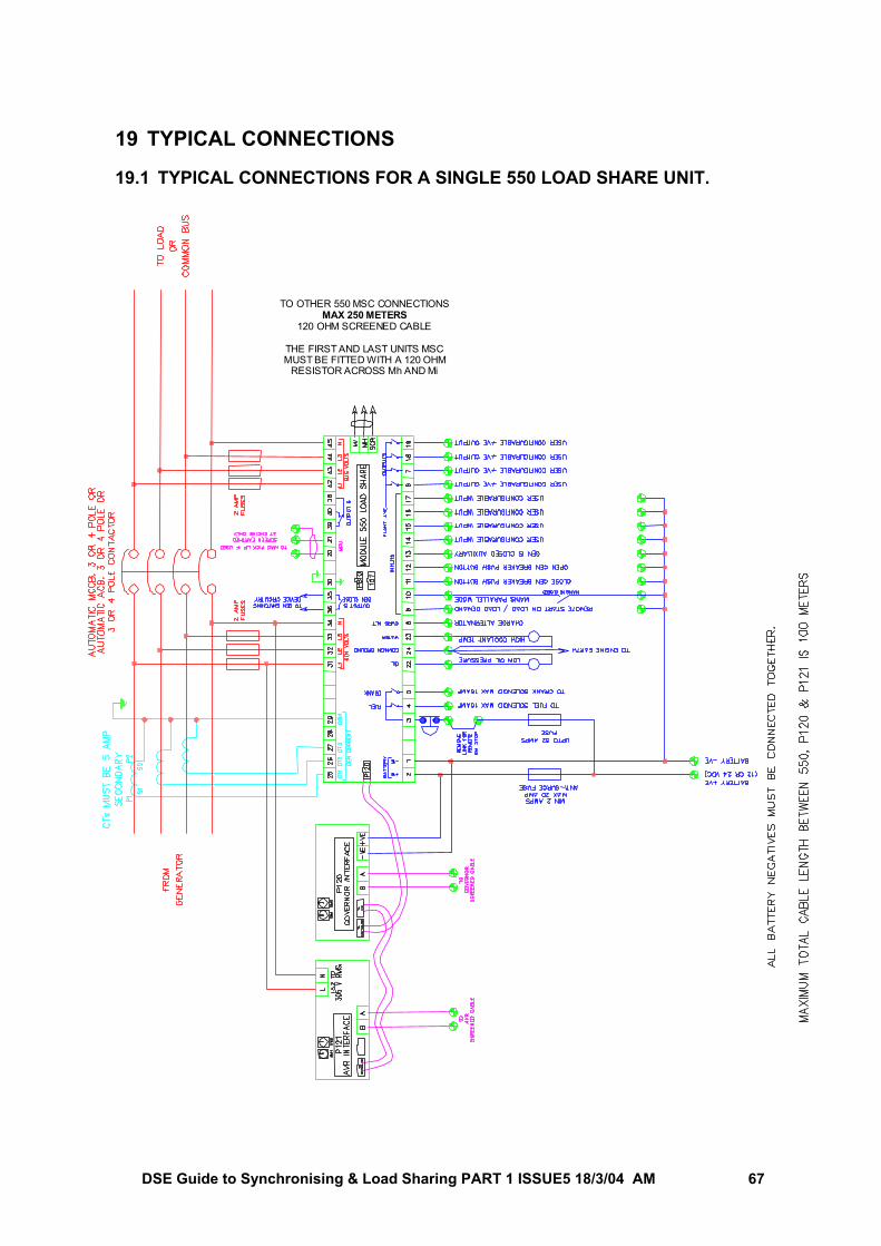
DSE Guide to Synchronising & Load Sharing PART 1 ISSUE5 18/3/04 AM 67
19 TYPICAL CONNECTIONS 19.1 TYPICAL CONNECTIONS FOR A SINGLE 550 LOAD SHARE UNIT.
TO OTHER 550 MSC CONNECTIONSMAX 250 METERS
120 OHM SCREENED CABLE
THE FIRST AND LAST UNITS MSCMUST BE FITTED WITH A 120 OHM
RESISTOR ACROSS Mh AND Mi
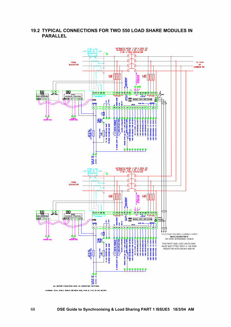
DSE Guide to Synchronising & Load Sharing PART 1 ISSUE5 18/3/04 AM 68
19.2 TYPICAL CONNECTIONS FOR TWO 550 LOAD SHARE MODULES IN PARALLEL
TO OTH ER 550 MSC C ONNECTION SMAX 250 M ETER S
120 OHM SCREENED CABLE
THE FIR ST AND LAST UN ITS MSCMUST BE F ITTED WITH A 120 OHM
RESISTOR ACR OSS M h AND Mi
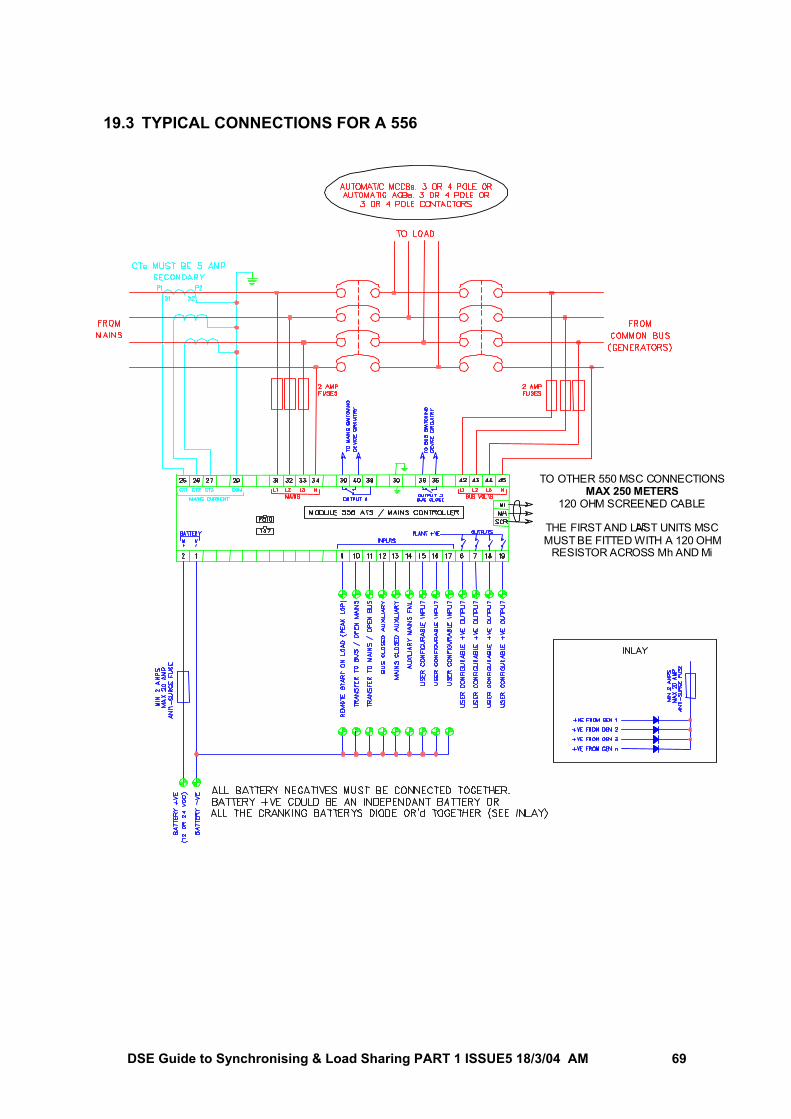
DSE Guide to Synchronising & Load Sharing PART 1 ISSUE5 18/3/04 AM 69
19.3 TYPICAL CONNECTIONS FOR A 556
TO OTHER 550 MSC CONNECTIONSMAX 250 METERS
120 OHM SCREENED CABLE
THE FIRST AND LAST UNITS MSCMUST BE FITTED WITH A 120 OHM
RESISTOR ACROSS Mh AND Mi
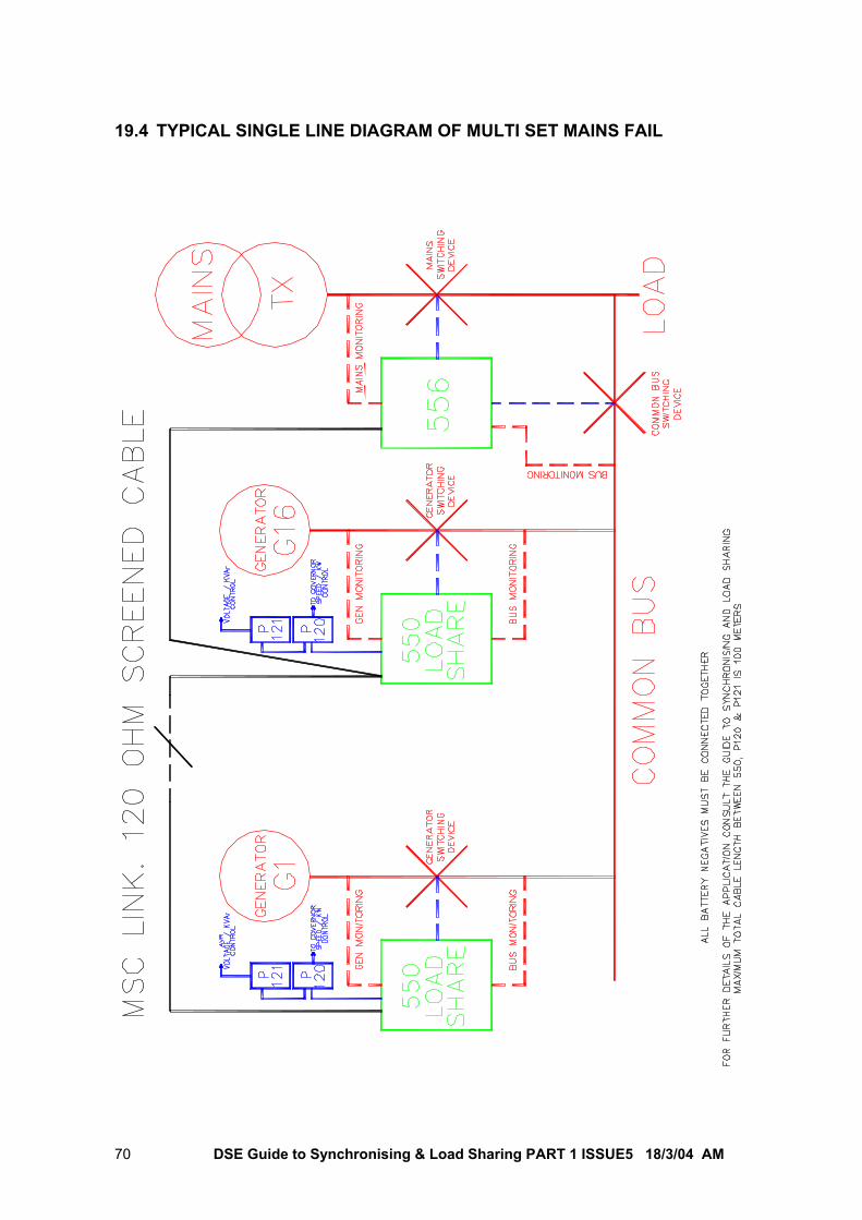
DSE Guide to Synchronising & Load Sharing PART 1 ISSUE5 18/3/04 AM 70
19.4 TYPICAL SINGLE LINE DIAGRAM OF MULTI SET MAINS FAIL
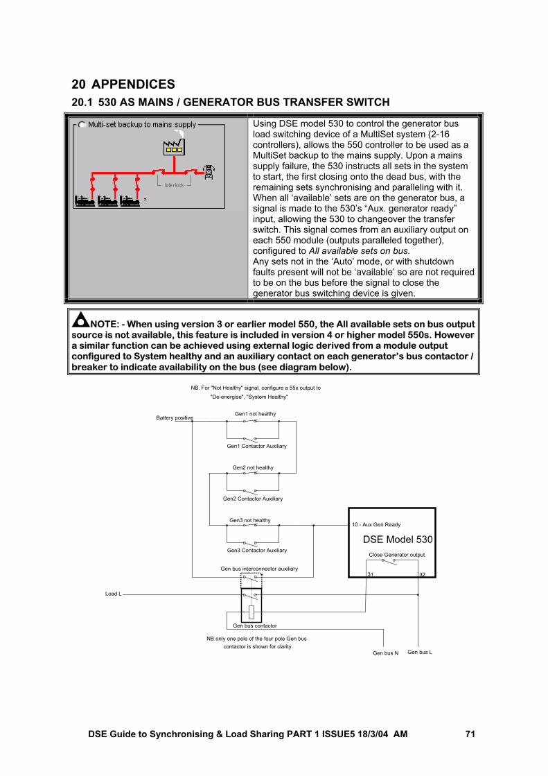
DSE Guide to Synchronising & Load Sharing PART 1 ISSUE5 18/3/04 AM 71
20 APPENDICES
20.1 530 AS MAINS / GENERATOR BUS TRANSFER SWITCH
Using DSE model 530 to control the generator bus load switching device of a MultiSet system (2-16 controllers), allows the 550 controller to be used as a MultiSet backup to the mains supply. Upon a mains supply failure, the 530 instructs all sets in the system to start, the first closing onto the dead bus, with the remaining sets synchronising and paralleling with it. When all ‘available’ sets are on the generator bus, a signal is made to the 530’s “Aux. generator ready” input, allowing the 530 to changeover the transfer switch. This signal comes from an auxiliary output on each 550 module (outputs paralleled together), configured to All available sets on bus. Any sets not in the ‘Auto’ mode, or with shutdown faults present will not be ‘available’ so are not required to be on the bus before the signal to close the generator bus switching device is given.
NOTE: - When using version 3 or earlier model 550, the All available sets on bus output source is not available, this feature is included in version 4 or higher model 550s. However a similar function can be achieved using external logic derived from a module output configured to System healthy and an auxiliary contact on each generator’s bus contactor / breaker to indicate availability on the bus (see diagram below).
Gen1 not healthy
Gen1 Contactor Auxiliary
Gen2 not healthy
Gen2 Contactor Auxiliary
Gen3 not healthy
Gen3 Contactor Auxiliary
10 - Aux Gen Ready
Battery positive
NB. For "Not Healthy" signal, configure a 55x output to
"De-energise", "System Healthy"
Gen bus interconnector auxiliary
Gen bus N
Close Generator output
Gen bus L
Load L
31 32
DSE Model 530
Gen bus contactor
NB only one pole of the four pole Gen buscontactor is shown for clarity