deepwater terminal – coal handling facilitydeepwater terminal - coal handling facility request for...
TRANSCRIPT

DEEPWATER TERMINAL – COAL HANDLING FACILITY REQUEST FOR PROPOSAL NO. 58809-DP07
Medium Voltage Electrical Equipment and Transformers
BIDDER’S ACKNOWLEDGEMENT Please return this page, via facsimile or email, informing us of your intention to bid or decline this Request for Proposal to: Kinder Morgan Terminals
3500 N. Causeway Blvd., Suite 210 Metairie, LA 70002
Attn: Ms. Carla Pierson-Hart Sr. Contract Administrator / Procurement Fax No: (303) 984-3141 Email: [email protected] Your confirmation is requested on or before Tuesday, December 18, 2012. Failure to comply with this request may be cause for removal of your company from our list of approved bidders and your ability to respond to our future requests for proposal. We will submit a bid on or before the Bid Due Date of Friday, January 4, 2013 @ 2:00 P.M., C.S.T. We do not intend to bid because: Company Name: Designated Representative: Signature Date Print Name Telephone Number: Fax Number: Email:

REQUEST FOR PROPOSAL NO. RFP – 58809– DP07
Medium Voltage Electrical Equipment and
Rev. 0
Transformers
DEEPWATER TERMINAL - COAL HANDLING FACILITY
REQUEST FOR PROPOSAL RFP – 58809 – DP07
MEDIUM VOLTAGE ELECTRICAL EQUIPMENT AND TRANSFORMERS
DEEPWATER TERMINAL
COAL HANDLING FACILITY PASADENA, TX
PROJECT NO. 58809
TABLE OF CONTENTS
1.0 INSTRUCTIONS TO BIDDERS
2.0 FORM OF PROPOSAL 3.0 GENERAL TERMS AND CONDITIONS
4.0 SPECIFICATIONS, DRAWINGS AND DATA
5.0 SELLER’S QUALITY SURVEILLANCE
6.0 EXPEDITING
7.0 SHIPPING AND PACKAGING INSTRUCTIONS 8.0 INVOICING INSTRUCTIONS
9.0 SALES AND USE TAX CERTIFICATE OF EXEMPTION (IF APPLICABLE)

REQUEST FOR PROPOSAL NO. RFP – 58809– DP07
Medium Voltage Electrical Equipment and Transformers
Rev. 0
DEEPWATER TERMINAL - COAL HANDLING FACILITY
Section 1- Instructions to Bidders Page 1 of 3
SECTION 1 - INSTRUCTION TO BIDDERS
1.1 BID REQUEST DOCUMENTS: The Bidder's attention is directed to all the documents, which form a part of this RFP. All forms and documents must be completed and submitted with the Bidder's Proposal. Any document required but not submitted with the Bid will be reason for non-acceptance. The Bid is to be in strict conformance with the Buyer's requirements as set forth in this RFP. If there is any variation from the Buyer's requirements, the Bidder shall itemize all variances in the Form of Proposal.
1.2 BID RESPONSE DATES:
The following RFP dates must be adhered to:
Bidder’s Acknowledgement Due Date: Tuesday, December 18, 2012
RFP Due Date by 2:00 pm C.S.T.: Friday, January 4, 2013 The bid and all related documents to be submitted with the request, must be received on or before the Bid Response Date as specified above, or as the Buyer deems necessary to extend the date. Bids will be considered and reviewed if sent via facsimile or email, provided that the receipt of the original bid and requested documents are received in our office within 24 hours from the bid due date. Bids received after the bid due date may not be opened and may be returned to the Bidder.
1.3 BID SUBMITTAL REQUIREMENTS:
The original bid, one (1) priced copy of the bid, and one (1) non-priced copy, each complete with all attachments and supplemental correspondence in compliance with the needs of the RFP and any other information the Bidder may want to have considered as part of his bid, shall be enclosed in a sealed envelope or box, with the following identifying labels. Failure to use these labels in submitting the bid may be cause for rejection of the bid due to the inadvertent early opening of the envelope or box.
Labeling: Deepwater SDW Coal Permitting Project Request for Proposal Number: DP07 -
Delivery address: Kinder Morgan Terminals Attn: Carla D. Pierson Hart
Medium Voltage Electrical Equipment and Transformers Bidder Name Number ____ of ____(as relevant)
Sr. Contracts Administrator /Procurement 3500 N. Causeway Blvd., Ste 210 Metairie, LA 70002
All submittals are to arrive by 2:00 pm, C.S.T. as stated in Article 1.2 “Bid Response Dates” above and in the Request for Proposal Letter. This time and date may be extended as deemed necessary by the Buyer.
1.4 BID VALIDITY PERIOD: The bid shall be valid for a period of 90 days.

REQUEST FOR PROPOSAL NO. RFP – 58809– DP07
Medium Voltage Electrical Equipment and Transformers
Rev. 0
DEEPWATER TERMINAL - COAL HANDLING FACILITY
Section 1- Instructions to Bidders Page 2 of 3
1.5 BASIS OF AWARD:
The Buyer reserves the right to accept or reject any or all bids, to waive any informality in the bids received. Unless otherwise stated in this RFP, the Buyer reserves the right to accept or reject one or more of the items in the bid and to divide the award among more than one of the Bidders if this, in the Buyer's judgment, is in the best interest of the Buyer. The Buyer does not guarantee any quantities or volumes in this RFP.
1.6 ALTERNATES:
Bidders are encouraged to submit alternate bids when they consider the alternate to be an improvement or more cost effective. However, the base bid must meet the requirements of the RFP. If Bidder wishes to propose any alternate(s), they should be itemized in the proposal under a separate attachment titled “BIDDERS PROPOSED ALTERNATES”. Bidder should be aware that consideration would be given in the selection of equipment for this project to maximize interchangeability of parts for the units quoted, operating efficiency, etc., where economically practical. When such consideration causes a significant increase in cost or loss of operating efficiency, alternates may be submitted.
1.7 SALES/ USER TAXES:
Any and all Sales/ User Taxes must be addressed and itemized in the RFP.
1.8 WARRANTY:
Per Section 3.0 General Terms and Conditions
1.9 DRAWINGS/ SPARE PARTS/ DATA SHEETS:
Where required in the RFP, (Section 4 Specifications, Drawings & Data, “Seller’s Documentation Index and Schedule”) the Bidder shall furnish with his proposal, hardcopy and/or CD’s of typical outline, arrangement and sectional drawings with descriptions of equipment, a priced and recommended spare part list, including completed required data sheets.
1.10 PROPRIETARY INFORMATION:
This RFP, and all accompanying attachments, are the property of the Buyer and are provided only for the purpose of enabling each potential Bidder to prepare and submit a bid in response thereto. The information contained or referred to in the RFP is not to be disclosed or released for any other use or purpose and must be returned to the Buyer when requested. The Bidder must advise if any of the submitted drawings or information is proprietary in nature.

REQUEST FOR PROPOSAL NO. RFP – 58809– DP07
Medium Voltage Electrical Equipment and Transformers
Rev. 0
DEEPWATER TERMINAL - COAL HANDLING FACILITY
Section 1- Instructions to Bidders Page 3 of 3
1.11 REQUEST FOR ADDITIONAL INFORMATION:
All technical and commercial clarifications, questions or need for additional information shall be directed to the following: Technical Request Kinder Morgan Terminals Attn: Sheridan Bosch Project Manager 4207 Pasadena Freeway Pasadena, TX 77503 P: 281-241-5709 F: 281-478-5631 Commercial Request Kinder Morgan Terminals Attn: Carla D. Pierson Hart Sr. Contracts Administrator / Procurement 3500 N. Causeway Blvd., Ste 210 Metairie, LA 70002 P: 504-620-4644 F: 303-984-3141

REQUEST FOR PROPOSAL NO. RFP – 58809– DP07 Medium Voltage Electrical
Equipment and Transformers
Rev. 0
DEEPWATER TERMINAL – COAL HANDLING FACILITY
Section 2- Form of Proposal Page 1 of 19
SECTION 2 - FORM OF PROPOSAL
2.1 GENERAL:
2.1.1 THIS FORM OF PROPOSAL MUST BE RETURNED WITH THE BIDDER'S PROPOSAL. Where a specific response is required of the Bidder, the Bidder shall include such response in the space provided or shall type in "See Attached", "None", "Included Above", or like words to indicate that he has read and understands the requirement. The Bidder's proposal will not be considered responsive unless completed in this manner. NO SPACES ARE TO BE LEFT BLANK.
2.1.2 The following summary of pricing and other information is offered in response to this RFP. By execution of this Form of Proposal, the Bidder agrees to furnish and deliver all items described in this RFP without deviation or exception (except as may be specifically noted below). It is understood that payment in accordance with the prices set forth shall constitute complete payment for the work specified.
2.2 PRICING:
2.2.1 Prices quoted shall be valid for ninety (90) days from the Bid Due Date specified and shall be firm for the delivery quoted.
2.2.2 Total price for all items in this RFP, excluding freight & sales/ user taxes:
$ ______________________________________________________________
Total freight costs, per the shipping terms in Section 2.7 of this Form of Proposal:
$ ______________________________________________________________
2.2.3 Total applicable sales/ user taxes: $ __________________________________
2.2.4 Total bid price: $__________________________________________________
NOTE: AN ITEMIZED PRICING BREAKDOWN MUST BE COMPLETED BY BIDDER IN THE SPACES PROVIDED IN ATTACHMENT A - PRICING
2.3 SPARE PARTS:
2.3.1 A.) Recommended spare parts cost for start-up of proposed equipment:
$
Is the cost included in 2.2.4 Total Bid Price? Yes No
Itemized start-up spare parts price listing attached in Attachment B?
Yes No

REQUEST FOR PROPOSAL NO. RFP – 58809– DP07 Medium Voltage Electrical
Equipment and Transformers
Rev. 0
DEEPWATER TERMINAL – COAL HANDLING FACILITY
Section 2- Form of Proposal Page 2 of 19
2.3.2 Cost of recommended spare parts for two year's operation: $
Is cost included in 2.2.4 Total Bid Price? Yes No
Itemized Two Year’s priced spare parts listing in Attachment C?
Yes No
2.3.3 Spare part prices are firm if the part is ordered within one (1) year from the Agreement date: Month/Day/Year
2.4 SPECIAL TOOLS:
2.4.1 Are special tools required for the operation and maintenance of quoted equipment? Yes No
Identify cost of special tools required, if any: $
2.4.2 Have special tools been included in 2.2.4 Total Bid Price? ______ Yes No
2.4.3 Itemized special tools price, enclosed in Attachment D?
Yes No 2.5 TESTING:
The Bidder shall confirm that, IF REQUIRED IN THE SPECIFICATIONS, prices quoted do include all costs for witnessed performance tests. Bidder shall show the cost of witness performance testing included in Attachment A?
Yes No If “No,” please explain. Lump Sum Cost of Witness Testing: $
Does the Bidder have adequate facilities to perform testing if required?
Yes No
If Bidder does not have adequate testing facilities and equipment (i.e., power supply, motors for pumps, steam, etc.) Bidder shall so state and explain its plan for meeting these requirements if applicable.
2.6 PAYMENT TERMS:
The payment due date should be shown as a duration period from either the date of the invoice or the delivery date and shall not be less than thirty (30) days thereafter.

REQUEST FOR PROPOSAL NO. RFP – 58809– DP07 Medium Voltage Electrical
Equipment and Transformers
Rev. 0
DEEPWATER TERMINAL – COAL HANDLING FACILITY
Section 2- Form of Proposal Page 3 of 19
If proposed, Progress Payments shall be considered as an exception to these conditions and will be subject to ten percent (10%) retention by the Buyer. However, if progress payments are proposed, the payment terms must define the amount of payment and the provisions under which these payments are to be made. In addition, each progress payment must be linked to a milestone(s) or actual work performed and is to be confirmed by the Buyer prior to payment. The milestone(s) must be described in detail (i.e. "major components" must be defined).
The Bidder is to advise its complete discount terms for payment by the Buyer in advance of Buyer's standard payment period of net thirty (30) days.
Discounts for early payment may be a factor in the evaluation of the Bidder's proposal.
Does Bidder accept the Buyer's payment terms? Yes No
If not, what are Bidder's proposed payment terms?
2.7 SHIPPING TERMS:
2.7.1 Project shipping terms are as follows:
A. DDP Destination: Deepwater Terminal
Attn: William (Bill) Holmes (Terminal Manager) 4207PasadenaFreeway Pasadena, TX 77503 Phone: 281-241-5704
2.7.2 Does Bidder accept the Buyer’s shipping terms? Yes ____ No ____. If Not, what are the Bidder's shipping terms:
2.7.3 What is the point of Origin(s) (Shipping point, Country and Zip Code)?
2.7.4 What is the name of final shipper(s) and physical address shipping point?
2.8 DRAWING SUBMITTAL AND EQUIPMENT DELIVERY SCHEDULE: 2.8.1 It is essential that the required delivery date of the goods specified herein be met.
The promised delivery dates quoted by the Bidder will be a key consideration in making an award. The Bidder should therefore quote the best delivery based on a realistic production schedule. In determining the promised delivery dates, allow 2 weeks for engineer’s drawing approval and return of drawings and data. The Buyer will accept electronically transmitted drawings using Auto Cad 14 or higher.

REQUEST FOR PROPOSAL NO. RFP – 58809– DP07 Medium Voltage Electrical
Equipment and Transformers
Rev. 0
DEEPWATER TERMINAL – COAL HANDLING FACILITY
Section 2- Form of Proposal Page 4 of 19
2.8.2 The following schedule will be the basis of the Bidder’s commitment for the
delivery of subject goods. The Bidder will be required, if awarded an order, to submit a schedule in Primavera P-3, Suretrak or MS Project Planner. If unavailable, the Bidder shall at a minimum provide a bar-chart schedule that is satisfactory to the Buyer. The schedule will be updated on a monthly basis with a brief narrative, indicating the status of major activities and areas of concern.
2.8.3 Project Required Delivery Date: Per Specification 01010 Section 4.0 2.8.4 Submittal of drawings and data required for review prior to start of fabrication/
manufacturing (see "Seller’s Documentation Index and Schedule" Section 3):
4 Weeks ARO
2.8.5 Assume drawing review by Engineer, including mailing time: 2 Weeks
2.8.6 Number of weeks required for delivery of equipment after receipt of reviewed drawings with “release to proceed” status. This period is to include completion of fabrication, shop inspections and testing, preparation for shipment and transportation to jobsite: Weeks
Note: If multiple drawing submittals or shipments are anticipated, Bidder is to submit a schedule, with the proposal, indicating major milestones.
Bidder confirms that the total time quoted above has allowed for sufficient time to meet the required delivery date. Yes No
If response is “NO,” please explain in the proposal. 2.8.7 The Bidder must provide a detailed preliminary schedule with the proposal
detailing the activities required to achieve the required project delivery date. The schedule will include, but not be limited to, the following activities:
A) Preparation and submission of approval of drawings and calculations
(allowing 2 weeks for approval); B) Material procurement; C) Testing and inspection; D) Preparation for shipment; E) Shipment; F) Delivery date;
2.9 COMPLIANCE WITH GENERAL TERMS AND CONDITIONS:
The Bidder agrees that, if awarded an order, he will accept the General Terms and Conditions in this RFP and in the subsequent Agreement. Additional Conditions, as defined and determined by the Buyer, may also be incorporated into a subsequent Agreement. Any exceptions taken by Bidder will be reviewed in the bid evaluation and may be cause for rejection of Bidder's proposal.
If the Bidder takes exceptions, differences shall be itemized in the Attachment F titled, "QUALIFICATIONS TO GENERAL TERMS AND CONDITIONS". No other terms or

REQUEST FOR PROPOSAL NO. RFP – 58809– DP07 Medium Voltage Electrical
Equipment and Transformers
Rev. 0
DEEPWATER TERMINAL – COAL HANDLING FACILITY
Section 2- Form of Proposal Page 5 of 19
conditions shall be binding upon the Buyer unless accepted by the Buyer and included in the Agreement.
___ No exceptions taken
___ Exceptions noted in Attachment F
2.10 COMPLIANCE WITH TECHNICAL SPECIFICATIONS:
The Bidder has reviewed and understands the specifications contained in this RFP and has verified his capability and willingness to furnish these items to conform to the requirements if awarded an Agreement in accordance with terms of this RFP. If the Bidder's proposal differs from these technical specifications in any way, the differences should be itemized in the Attachment G titled, "QUALIFICATIONS TO TECHNICAL SPECIFICATIONS".
___ No exceptions taken
___ Exceptions noted on Attachment G
2.11 SUBCONTRACTOR/ SUB-SUPPLIERS:
2.11.1 Bidder must state whether any major portion of the order will be subcontracted and give the name and location of all sources intended to fulfill the requirements of this Agreement. Should the Bidder be successful in receiving an order, the Buyer reserves the right to review the qualifications and approve the selection of any subcontractor/ sub-supplier so named below:
Subcomponent:
Name of Subcontractor/ Sub-supplier:
Address:
[Use a separate page to list more than one major Subcontractor/ Sub-supplier]
2.11.2 Bidder must state manufacturer and country of origin for all major subcomponents not fabricated or manufactured in the USA:
Material:
Name of Manufacturer:
Country of Origin:
[Use a separate page to list more than one foreign manufacturer]
2.12 PREVENTIVE MAINTENANCE REQUIREMENTS: 2.15.1 Preventive Maintenance During Storage:
REQUEST FOR PROPOSAL NO. RFP – 58809– DP07 Medium Voltage Electrical
Equipment and Transformers
Rev. 0
DEEPWATER TERMINAL – COAL HANDLING FACILITY
Section 2- Form of Proposal Page 6 of 19
Bidder shall state if the equipment requires maintenance during the period of storage or prior to operation.
YES NO If yes, the Bidder is required to state in a separate attachment, the extent, type and intervals of preventive maintenance required. The Bidder shall also authorize the Buyer to conduct this preventive maintenance on its behalf or include a cost for such preventative maintenance if the Buyer cannot perform this task or the Bidder does not want to relinquish this activity to the Buyer or a third party.
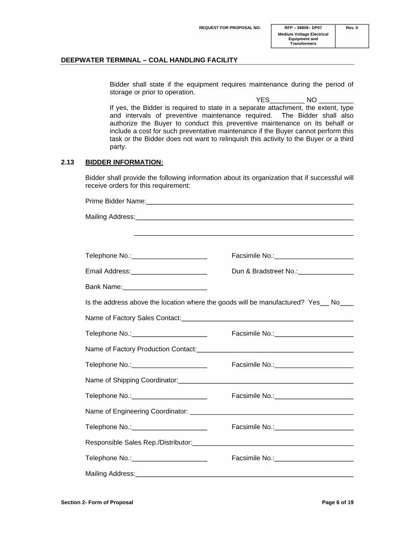
2.13 BIDDER INFORMATION:
Bidder shall provide the following information about its organization that if successful will receive orders for this requirement:
Prime Bidder Name: Mailing Address: Telephone No.: Facsimile No.: Email Address: Dun & Bradstreet No.: Bank Name: Is the address above the location where the goods will be manufactured? Yes No Name of Factory Sales Contact: Telephone No.: Facsimile No.: Name of Factory Production Contact: Telephone No.: Facsimile No.: Name of Shipping Coordinator: Telephone No.: Facsimile No.: Name of Engineering Coordinator:
Telephone No.: Facsimile No.: Responsible Sales Rep./Distributor: Telephone No.: Facsimile No.: Mailing Address:

REQUEST FOR PROPOSAL NO. RFP – 58809– DP07 Medium Voltage Electrical
Equipment and Transformers
Rev. 0
DEEPWATER TERMINAL – COAL HANDLING FACILITY
Section 2- Form of Proposal Page 7 of 19
Contact Person: Telephone No.: Facsimile No.:
Email Address:
2.14 SMALL/ DISADVANTAGED/ MINORITY/ WOMEN-OWNED BUSINESS STATUS:
Indicate whether your firm is a:
Small Business: Yes _____ No _____
Disadvantaged Minority Business: Yes _____ No _____
Woman-Owned Business: Yes _____ No _____
Other protected "Enterprise": Category
Indicate the criteria (local, state or federal) under which you qualify, and include a copy of certification, if available:
2.15 ON-SITE SERVICES REPRESENTATIVE INFORMATION:
If required by the RFP, or recommended by the Bidder, technical services for erection/ installation/ start-up/ training field service representative(s) are to be shown in the Bidder’s proposal. The individual will act in advisory capacity only and will be required to provide guidance during erection/ installation/ start-up/ training. The field service representative(s) will be subject to jobsite safety and procedure requirements, inclusive of, but not limited to, insurance requirements. The Buyer will issue a technical service order at a later date, if required, for this work.
2.15.1 The Bidder shall state the all-inclusive cost (i.e. cost of travel, lodging, meals, etc.) for a Field Service Representative(s) during erection/ installation/ start-up/ training.
2.15.2 The Bidder shall provide a separate lump sum cost for all field services in connection with this order. $
2.15.3 The Bidder shall state the number of days included in Bidder’s price for the Field Service Representative(s).
Work Days
Point of Origin of Field Service Representative(s) trip (City & State):
2.15.4 Are field services required by the Bidder/ Manufacturer to meet the warranty requirements defined in the General and Special Conditions?
Yes No

REQUEST FOR PROPOSAL NO. RFP – 58809– DP07 Medium Voltage Electrical
Equipment and Transformers
Rev. 0
DEEPWATER TERMINAL – COAL HANDLING FACILITY
Section 2- Form of Proposal Page 8 of 19
2.15.5 The Bidder will provide the lead time required from receipt of Buyer’s notification, to the time the Field Service Representative(s) would depart for the jobsite:
Days.
2.15.6 The Bidder will provide the name, telephone and fax numbers of person to be contacted for coordination of field services:
Name:
Telephone No.: Fax No.:
2.15.7 The Bidder will provide the address or nearest service point to the jobsite from which replacement parts are available for all major equipment supplied, complete with contact(s), telephone and fax numbers.
Name of Contact: Company Name:
Telephone No.: Facsimile No.:
2.15.8 Compensation:
In the event that the Buyer requests field services during erection/ installation/ start-up and or training in addition to those include in the base bid, the following rates shall apply:
2.15.8.1 Hourly rate and definition of regular weekday hours. $ / Hr 2.15.8.2 Hourly rate and definition of weekday overtime hours. $ / Hr 2.15.8.3 Hourly rate and definition of Saturday hours. $ / Hr 2.15.8.4 Hourly rate and definition of Sunday hours. $ / Hr 2.15.8.5 Hourly rate and definition of holiday hours. $ / Hr 2.15.8.6 Hourly rate and definition of travel time not to exceed 8 hours per day
$ / Hr 2.15.8.7 Hourly rate and definition of standby time. $ / Hr 2.15.8.8 Estimated cost of travel per trip and description of mode of transportation
to be used $ / Trip Field representative(s) departure location (City/ State/ Country):
2.15.9 Responsibility:

REQUEST FOR PROPOSAL NO. RFP – 58809– DP07 Medium Voltage Electrical
Equipment and Transformers
Rev. 0
DEEPWATER TERMINAL – COAL HANDLING FACILITY
Section 2- Form of Proposal Page 9 of 19
The Bidder’s Representative(s) will be fully experienced and properly qualified to advise and give direction for the services required by this Agreement and shall act for, and on behalf of, the Bidder. The Bidder certifies that he is properly licensed, equipped, organized and financed to provide such advice and direction. The Bidder shall act independently and not as an agent of the Buyer in performing this work and shall maintain complete control and responsibility over his employees.

REQUEST FOR PROPOSAL NO. RFP – 58809– DP07 Medium Voltage Electrical
Equipment and Transformers
Rev. 0
DEEPWATER TERMINAL – COAL HANDLING FACILITY
Section 2- Form of Proposal Page 10 of 19
ATTACHMENT A-
SCOPE OF WORK & BID BREAKDOWN Bidder shall be compensated for the engineering, supply, manufacture, factory acceptance testing and delivery DDP to the Jobsite of the Goods, with the fully inclusive lump sum price of $ . Buyer reserves the right to exercise the option for installation supervision as per the Unit Rates included in Section 2 “Form of Proposal” and for spares as per the Unit Rates included in Attachments B, C & D.
ITEM DESCRIPTION UNIT QTY UNIT
PRICE ($) TOTAL($)
0
Furnish all labor, supervision, materials, equipment and all other items necessary for the design, supply and delivery of Medium Voltage Electrical Equipment and Transformers as described in the specifications and as per the attachments hereto:
1. 2.5 MVA 12.47KV/4.16KV Pad Mounted Transformers (TX03A) EA 1
2. 2.0 MVA 12.47KV/4.16KV Pad Mounted Transformers (TX07A) EA 1
3. 1.5 MVA 12.47KV/4.16KV Pad Mounted Transformers (TX04A) EA 1
4. 1.0 MVA 12.47KV/4.16KV Pad Mounted Transformers (TX08A) EA 1
5. 1.5 MVA 12.47KV/480V Pad Mounted Transformers (TX08B) EA 1
6. 1.0 MVA 12.47KV/480V Pad Mounted Transformers (TX09B, TX05, TX06, TX07B) EA 4
7. .5 MVA 12.47KV/480V Pad Mounted Transformers (TX03B, TX04B) EA 2
8. 1,000KVAR 15KV Power Factor Correction Capacitor Bank EA 1
9. 1,300KVAR 15KV Power Factor Correction Capacitor Bank EA 1
10. Medium Voltage Switchgear (MS1) ER 1

REQUEST FOR PROPOSAL NO. RFP – 58809– DP07 Medium Voltage Electrical
Equipment and Transformers
Rev. 0
DEEPWATER TERMINAL – COAL HANDLING FACILITY
Section 2- Form of Proposal Page 11 of 19
11. Medium Voltage Switchgear (MS2) EA 1
12. 600A 5KV Motor Control Center (MCC-MV03) EA 1
13. 1200A 5KV Motor Control Center (MCC-MV04) EA 1
14. 600A 5KV Motor Control Center (MCC-MV07) EA 1
15. 600A 5KV Motor Control Center (MCC-MV08) EA 1
16. Installation, Training, and Commissioning Services Lot
17.
Engineering data, documentation, erection procedures, pre-commissioning and commissioning procedures, operation and maintenance manuals (Per Section 4 Specifications, Drawings & Data).
Lot
18. TOTAL COST FOR FIELD SERVICES REP DURING (INSTALLATION/START-UP) __ Working Days Lot
19. PREPARATION AND PACKAGING FOR SHIPMENT AS DESCRIBED IN SECTION 7 SHIPPING & PACKING
Lot
20. TOTAL FIRM PRICE FOR ITEMS (1-19) (List under Item 2.2.2 page 1) Lot
21. TOTAL FREIGHT COSTS DDP JOBSITE (INCLUDING PERMITS AND ESCORTS, IF APPLICABLE) (List under Item 2.2.2 page 1)
Lot
22. TOTAL SALES/ USER TAXES (List under Item 2.2.3 page 1) Lot
Sub Total $ - Taxes $
BID GRAND TOTAL $ -

REQUEST FOR PROPOSAL NO. RFP – 58809– DP07 Medium Voltage Electrical
Equipment and Transformers
Rev. 0
DEEPWATER TERMINAL – COAL HANDLING FACILITY
Section 2- Form of Proposal Page 12 of 19
ATTACHMENT B
RECOMMENDED START-UP SPARES
BIDDER shall complete the following table as described in Article 2.3, “Spare Parts, Section 2 of “Form of Proposal”. Item Qty. Description Unit Cost Total Cost TOTAL FIRM PRICE FOR ITEMS (1-XX) 1 Lot PREPARATION AND PACKAGING FOR SHIPMENT AS
DESCRIBED IN SECTION 6 SHIPPING & PACKING
1 Lot TOTAL FREIGHT COSTS DDP DESTINATION (INCLUDING
PERMITS AND ESCORTS, IF APPLICABLE) (List in Attachment A)
1 Lot TOTAL SALES/ USER TAXES TOTAL LUMP SUM COST (List in Section 2.3.1)

REQUEST FOR PROPOSAL NO. RFP – 58809– DP07 Medium Voltage Electrical
Equipment and Transformers
Rev. 0
DEEPWATER TERMINAL – COAL HANDLING FACILITY
Section 2- Form of Proposal Page 13 of 19
ATTACHMENT C
RECOMMENDED TWO YEAR’S OPERATING SPARES BIDDER shall complete the following table as described in Article 2.3, “Spare Parts, Section 2 of “Form of Proposal”. Item Qty. Description Unit Cost Total Cost TOTAL FIRM PRICE FOR ITEMS (1-XX) 1 Lot PREPARATION AND PACKAGING FOR SHIPMENT AS
DESCRIBED IN SECTION 7 SHIPPING & PACKING
1 Lot TOTAL FREIGHT COSTS DDP DESTINATION (INCLUDING
PERMITS AND ESCORTS, IF APPLICABLE) (List in Attachment A)
1 Lot TOTAL SALES/ USER TAXES TOTAL LUMP SUM COST (List in Section 2.3.2)

REQUEST FOR PROPOSAL NO. RFP – 58809– DP07 Medium Voltage Electrical
Equipment and Transformers
Rev. 0
DEEPWATER TERMINAL – COAL HANDLING FACILITY
Section 2- Form of Proposal Page 14 of 19
ATTACHMENT D
SPECIAL TOOLS BIDDER shall complete the following table as described in Article 2.4, “Special Tools, Section 2 “Form of Proposal”. Item Qty. Description Unit Cost Total Cost TOTAL FIRM PRICE FOR ITEMS (1-XX) 1 Lot PREPARATION AND PACKAGING FOR SHIPMENT AS
DESCRIBED IN SECTION 7 SHIPPING & PACKING
1 Lot TOTAL FREIGHT COSTS DDP DESTINATION (INCLUDING
PERMITS AND ESCORTS, IF APPLICABLE) (List in Attachment A)
1 Lot TOTAL SALES/ USER TAXES TOTAL LUMP SUM COST (List in Section 2.4.1)

REQUEST FOR PROPOSAL NO. RFP – 58809– DP07 Medium Voltage Electrical
Equipment and Transformers
Rev. 0
DEEPWATER TERMINAL – COAL HANDLING FACILITY
Section 2- Form of Proposal Page 15 of 19
ATTACHMENT E
ALTERNATIVES BIDDER shall complete the following table as described in Article 1.6, “INSTRUCTIONS TO BIDDERS” with the price and schedule impact indicated. BIDDERS PROPOSED ALTERNATIVES Item Description Recommended
change to Design
Reasons for proposed Alternative
Impact upon Base Bid should Buyer accept Alternative
Price impact Schedule impact
(Note: BIDDER may retype this page, but shall comply with this format).

REQUEST FOR PROPOSAL NO. RFP – 58809– DP07 Medium Voltage Electrical
Equipment and Transformers
Rev. 0
DEEPWATER TERMINAL – COAL HANDLING FACILITY
Section 2- Form of Proposal Page 16 of 19
ATTACHMENT F
QUALIFICATIONS TO GENERAL AND SPECIAL CONDITIONS BIDDER shall complete the following table as described in Article 2.9, “FORM OF PROPOSAL” with the price impact (if applicable) inserted. BIDDERS PROPOSED COMMERCIAL QUALIFICATIONS Article Specific wording
affected by proposed qualification or exception (indicate addition, deletion or change)
Reason for qualification or exception
Proposed rewording Price impact if Buyer rejects qualification or exception
(Note: BIDDER may retype this page, but shall comply with this format).

REQUEST FOR PROPOSAL NO. RFP – 58809– DP07 Medium Voltage Electrical
Equipment and Transformers
Rev. 0
DEEPWATER TERMINAL – COAL HANDLING FACILITY
Section 2- Form of Proposal Page 17 of 19
ATTACHMENT G
QUALIFICATIONS TO SPECIFICATIONS BIDDER shall complete the following table as described in Article 2.10, FORM OF PROPOSAL with the price impact (if applicable) inserted. BIDDERS PROPOSED TECHNICAL QUALIFICATIONS Spec. Number
Specific wording affected by proposed qualification or exception (indicate addition, deletion or change)
Reason for qualification or exception
Proposed rewording Price impact if Buyer rejects qualification or exception
(Note : BIDDER may retype this page, but shall comply with this format).

REQUEST FOR PROPOSAL NO. RFP – 58809– DP07 Medium Voltage Electrical
Equipment and Transformers
Rev. 0
DEEPWATER TERMINAL – COAL HANDLING FACILITY
Section 2- Form of Proposal Page 18 of 19
2.16 BID CHECK LIST: Bidder shall complete all items listed below. ITEM SUBJECT YES NO
1
Has the BIDDER submitted the original bid, one (1) priced copy of the bid, and one (1) non-priced copy?
2 Is Bid valid for acceptance for 90 days? 3 Are prices fixed and firm for duration of Agreement if accepted within above date? 4 Does BIDDER accept the Warranty Period (Article 1.8)? 5 Does the BIDDER accept the Payment Terms (Article 2.6)? 6 Does the BIDDER accept the Shipping Terms (Article 2.7)? 7 Does the BIDDER accept the Delivery Schedule (Article 2.8)? 8 Has the BIDDER submitted a proposed preliminary Detailed Time Schedule (Article
2.8.7)?
9 Does the BIDDER accept General Terms and Conditions (Article 2.9)? 10 Does the BIDDER comply with the Technical Specifications (Article 2.10)? 11 Has the BIDDER submitted Subcontractor/ Sub-supplier information (Article 2.11)? 12 Has the BIDDER submitted Preventive Maintenance information (Article 2.12)? 13 Has BIDDER submitted Bidder Information (Article 2.13)? 14 Has BIDDER submitted Business Status if applicable (Article 2.14)? 15 Has BIDDER submitted On Site Service Representative information (Article 2.15)? 16 Has BIDDER submitted Sample Certificate of Insurance (Section 3.18)? 17 Has the BIDDER completed the Declaration of Bidder (Article 2.17)? 18 Has BIDDER submitted any Alternatives & Price/ Schedule impacts
(Attachment E)?
19 Has BIDDER submitted any commercial qualifications & pricing impacts to the specifications included in the Invitation to Bid documents? (Attachment F)?
20 Has BIDDER submitted any technical qualifications & pricing impacts to the specifications included in the Invitation to Bid documents? (Attachment G)?
21 Has BIDDER submitted the completed Form of Proposal (Section 2)? 22 Has BIDDER submitted an itemized pricing breakdown including: Itemized unit
prices, (Section 2, Attachment A Scope of Work)?
23 Has BIDDER submitted Attachment B, (Recommended Start-Up), Attachment C, (Recommended Two Year Spares), and Attachment D (Special Tools) Lists (Section 2)?
24 Has BIDDER submitted the completed requested Data Sheets attached to the technical specifications Section 4, Specifications, Drawings & Data )?
25 Has BIDDER submitted the requested drawings and documents (Section 4, Specifications, Drawings & Data)?
26 Has BIDDER submitted requested QA/QC documents (Section 4, Specifications, Drawings & Data)?
27 Has BIDDER submitted drawings/spare parts lists & data sheets per Seller’s Documentation Index and Schedule (Section 4, Specifications, Drawings & Data)?
REQUEST FOR PROPOSAL NO. RFP – 58809– DP07 Medium Voltage Electrical
Equipment and Transformers
Rev. 0
DEEPWATER TERMINAL – COAL HANDLING FACILITY
Section 2- Form of Proposal Page 19 of 19
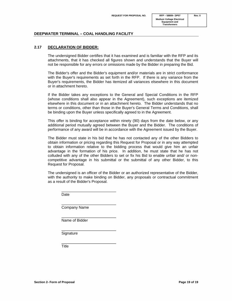
2.17 DECLARATION OF BIDDER:
The undersigned Bidder certifies that it has examined and is familiar with the RFP and its attachments, that it has checked all figures shown and understands that the Buyer will not be responsible for any errors or omissions made by the Bidder in preparing the Bid.
The Bidder's offer and the Bidder's equipment and/or materials are in strict conformance with the Buyer's requirements as set forth in the RFP. If there is any variance from the Buyer's requirements, the Bidder has itemized all variances elsewhere in this document or in attachment hereto.
If the Bidder takes any exceptions to the General and Special Conditions in the RFP (whose conditions shall also appear in the Agreement), such exceptions are itemized elsewhere in this document or in an attachment hereto. The Bidder understands that no terms or conditions, other than those in the Buyer's General Terms and Conditions, shall be binding upon the Buyer unless specifically agreed to in the Agreement.
This offer is binding for acceptance within ninety (90) days from the date below, or any additional period mutually agreed between the Buyer and the Bidder. The conditions of performance of any award will be in accordance with the Agreement issued by the Buyer.
The Bidder must state in his bid that he has not contacted any of the other Bidders to obtain information or pricing regarding this Request for Proposal or in any way attempted to obtain information relative to the bidding process that would give him an unfair advantage in the formation of his price. In addition, he must state that he has not colluded with any of the other Bidders to set or fix his Bid to enable unfair and/ or non-competitive advantage in his submittal or the submittal of any other Bidder, to this Request for Proposal.
The undersigned is an officer of the Bidder or an authorized representative of the Bidder, with the authority to make binding on Bidder, any proposals or contractual commitment as a result of the Bidder's Proposal.
Date
Company Name
Name of Bidder
Signature
Title

REQUEST FOR PROPOSAL NO. RFP – 58809– DP07
Medium Voltage Electrical
Rev. 0
Equipment and Transformers
DEEPWATER TERMINAL – COAL HANDLING FACILITY
Section 3 – KM PO Terms and Conditions Page 1 of 1
SECTION 3 – KMP PO TERMS AND CONDITIONS

TERMS AND CONDITIONS OF PURCHASE
<<Seller Name>> as Seller - Effective ________, 20__ _____________________________
_______________
Rev 2.3 Page 1 of 10 03-13-12
1.0 OFFER AND ACCEPTANCE
1.1. The Purchase Order is an offer by the Kinder Morgan (Kinder Morgan, Inc., a Delaware corporation, or Kinder Morgan Energy Partners, L.P) entity named on the face of the Purchase Order (COMPANY) to purchase materials, goods, equipment, parts and associated services further described, referenced or otherwise inferred as included hereunder (hereinafter collectively the GOODS) from the entity to which it is addressed (SELLER). The Kinder Morgan entity named on the face of the Purchase Order (COMPANY) attached hereto shall be solely responsible for the liabilities and obligations set forth in these Purchase Order Terms & Conditions under which the Purchase Order is being issued, as the same shall apply to the GOODS purchased and/or services to be performed pursuant hereto. In the event the Kinder Morgan entity executing this Purchase Order is doing so as agent for one of its subsidiary or affiliate entities then such subsidiary or affiliate entity shall be considered the COMPANY hereunder for all purposes and the Kinder Morgan entity acting as agent shall have no liability or obligation hereunder except as otherwise expressly stated on the face of the Purchase Order.
1.2. The parties agree that the Purchase Order shall consist of the cover sheet of the Purchase Order, these Terms and Conditions, and all specifications, drawings, notes, instructions or technical data referred or attached to the Purchase Order, and in the event of any conflict, the cover sheet of the Purchase Order shall control followed by these Terms and Conditions, followed by any terms and conditions contained in supporting documentation provided by COMPANY. But for the terms and conditions contained in this Purchase Order, COMPANY would not have entered into this transaction. SELLER hereby agrees that by accepting this order it agrees to be bound by COMPANY’s terms and conditions to the exclusion of all others, notwithstanding any term or condition contained in any of SELLER’s documents or otherwise communicated orally or in writing by SELLER. Any alteration of this Purchase Order without the specific written agreement of COMPANY is hereby objected to and rejected, notwithstanding that either party may have commenced performance hereunder.
1.3. Acceptance of the Purchase Order shall occur by one or more of the following acts:
1.3.1. signing and returning a copy of the Purchase Order;
1.3.2. delivery of any of the GOODS;
1.3.3. commencement of performance; or
1.3.4. express acknowledgement of the terms set forth herein.
1.4. Acceptance of the GOODS will not constitute acceptance by COMPANY of SELLER’s terms and conditions. Any such acceptance by COMPANY is expressly conditional upon the consent of SELLER to the terms and conditions of the Purchase Order, and no other forms of acceptance except those stated herein or agreed to by COMPANY will be considered acceptance by COMPANY. Prior dealing between the parties or usage of trade shall not be relevant to supplement or explain any term used in the Purchase Order.
2.0 PRICE; TERMS AND INVOICING
2.1. Unless otherwise stated, unit prices are as stated at date of issuance of the Purchase Order, are not subject to escalation, and are exclusive of all federal, state, and local excise, sales and use, and any other type of taxes, duties, customs, fees or other governmental assessments. Any reduction in SELLER’s costs of providing GOODS from those in force on the date of the Purchase Order due to a reduction in the taxes or other assessments ultimately paid or owed in connection therewith shall be paid to COMPANY by SELLER reducing the price of the GOODS.
2.2. Invoices shall be addressed as directed by COMPANY and shall contain the Purchase Order number, line item numbers, unit of measure, description of line items, sizes, quantities, unit prices, and extended totals. Applicable charges for freight and taxes shall be stated separately. Bills of lading or express receipts shall accompany such invoices. To accommodate COMPANY’s Accounts Payable systems software, costs for labor and/or services shall be billed separately and under different invoice numbers than for materials and equipment.

TERMS AND CONDITIONS OF PURCHASE
<<Seller Name>> as Seller - Effective ________, 20__ ______________________
______________________
Rev 2.3 Page 2 of 10 03-13-12
2.3. Invoices shall be payable on terms stated on the face of the Purchase Order and shall not include any terms or conditions included on or submitted with SELLER’s invoice. The time for payment shall commence with the latest of
2.3.1. actual receipt of invoice and supporting documents,
2.3.2. inspection and acceptance of the GOODS,
2.3.3. compliance by SELLER with all requirements of the Purchase Order, or
2.3.4. the date of receipt of the corrected invoice (in the event that invoices are returned for corrections). Unless freight, taxes and other charges are itemized, any applicable discount will be taken on the full amount of the invoice(s), and all payments are subject to adjustment for offset, shortage or rejection.
2.4. Delayed submittal of Invoices and Non-payment
2.4.1. Any costs for which SELLER does not submit an invoice to COMPANY within sixty (60) days after the month in which such Goods are received by COMPANY shall be deemed to have been provided by SELLER without compensation; provided however, that if prior to the end of such sixty (60) day period, SELLER requests in writing from COMPANY a further extension of time for submitting such invoice (stating the reasons therefore and the amount of additional time requested), and COMPANY elects to authorize such extension in writing, SELLER shall have until the end of the extension period to submit such invoice; and provided further, that nothing in this Purchase Order shall affect SELLER’S right to submit invoices within a longer period of time if so afforded by applicable statute.
3.0 DELIVERY; TITLE AND RISK OF LOSS
3.1. Unless otherwise stated on the face of the Purchase Order:
3.1.1. time is of the essence in SELLER performing and delivering the GOODS, and if there is a milestone schedule attached to the Purchase Order, in meeting each of the stated milestones;
3.1.2. the GOODS shall be shipped DDP destination (INCOTERMS 2010), by common carrier acceptable to SELLER;
3.1.3. title to the GOODS shall transfer to COMPANY upon the earlier of any payment made by COMPANY to SELLER and all completed or partially completed GOODS and to all materials delivered or stored which are to become part of the completed GOODS shall be in COMPANY’S name. However, liability for loss or damage to all such GOODS or materials, by whatsoever nature caused, shall remain with SELLER until delivery is complete at destination.
3.1.4. delivery shall not be deemed to be complete until all the GOODS have been received and accepted by COMPANY and risk of loss shall be and remain with SELLER until that time; and
3.1.5. if any or all of the GOODS are not accompanied by a packing slip, COMPANY’s count or weight for the entire Purchase Order shall be conclusive. SELLER shall transfer good and marketable title in and to the GOODS free and clear of any and all claims, charges or other encumbrances. If COMPANY, in its reasonable judgment, requires SELLER to execute COMPANY’s Facility Access Agreement prior to effecting deliveries called for by this Purchase Order, such execution shall become part of SELLER’s performance hereunder. COMPANY will furnish a sample Facility Access Agreement to SELLER upon request.
4.0 PACKAGING AND LABELING
All GOODS furnished under the Purchase Order shall be suitably packed, marked and shipped in accordance with the requirements of the carrier and in a manner to secure the lowest transportation cost, and no additional charges shall

TERMS AND CONDITIONS OF PURCHASE
<<Seller Name>> as Seller - Effective ________, 20__ ______________________
______________________
Rev 2.3 Page 3 of 10 03-13-12
be made to COMPANY for such packing, marking, shipping or any other costs of transportation, nor shall COMPANY be charged for demurrage or storage unless otherwise stated herein. The outside of each box, crate, bale or other containment device shall be marked with COMPANY’s Purchase Order number, SELLER’s name, shipper’s name (if different from SELLER), shipping point of origin, and COMPANY’s designated name and destination. Where multiple packages comprise a single shipment to the same destination, then each package shall be marked consecutively. Such marking shall include, but not be limited to a type of marking similar to “Carton 1 of 2”, “Carton 2 of 2”, etc. Packing slips with the Purchase Order number and exact quantity and description of GOODS must accompany each shipment. GOODS imported into Canada must be supported by two copies of the Canadian Customs invoice, the SELLER’s commercial invoice, and if the GOODS qualify under NAFTA rules of origin, a NAFTA Certificate of Origin signed by the SELLER’s Controller or Chief Financial Officer, all of which must be forwarded via courier or fax, on the day of shipment to COMPANY or its custom broker as designated on the face of the Purchase Order. In the event authorities for U.S. or Canadian Customs deem the GOODS ineligible for the NAFTA tariff program where NAFTA has been used to determine pricing of the GOODS then SELLER shall be liable for any and all duties, interest and penalties, retroactive to the first occurrence of shipping, and any administrative fee charged by COMPANY to offset the cost of resources utilized in any customs audit.
5.0 SHIPPING
5.1. If the Purchase Order stipulates that SELLER is required to transport the GOODS, COMPANY reserves the right to inspect and review SELLER’s logistics, transportation and packing plan. In addition, SELLER shall as appropriate:
5.1.1. use only properly licensed and insurable carriers for required transportation logistics services; and
5.1.2. package and transport the GOODS to the highest commercial standard practices of the industry in order to prevent damage during transport.
5.1.3. In the event COMPANY will be insuring the GOODS during transport SELLER shall also:
5.1.3.1. respond to COMPANY’s insurance representatives’ reasonable recommendations regarding packaging and transporting the GOODS and the loading plan on the vehicle or vessel to prevent damage to the GOODS during transit;
5.1.3.2. expressly acknowledge and agree to defer transporting the GOODS until the insurance representative conducts a load and stowage survey and issues an insurance certificate attesting that its recommendations were implemented for such transit or the insurance representative expressly waives in writing such requirement for shipment;
5.1.3.3. provide the insurance representative with a stowage and packing plan forty-five (45) days prior to loading; and
5.1.3.4. acknowledge that all efforts and delays associated with receiving the insurability certificate shall not be grounds for extension of the shipment/delivery date stipulated in the Purchase Order.
6.0 INSPECTION AND TESTING
6.1. All GOODS provided hereunder shall at all times be subject to inspection and testing by COMPANY and its representatives. SELLER shall furnish COMPANY with a production schedule for the GOODS upon receipt of the Purchase Order and subsequent production schedules shall be submitted every two (2) weeks thereafter. If any of the GOODS are defective or otherwise not in conformity with the requirements of the Purchase Order, then COMPANY, in addition to any other rights, may:
6.1.1. reject the same for full credit;
6.1.2. conditionally accept the shipment, fix the GOODS to conform to COMPANY’s requirements as stated in the Purchase Order, and either

TERMS AND CONDITIONS OF PURCHASE
<<Seller Name>> as Seller - Effective ________, 20__ ______________________
______________________
Rev 2.3 Page 4 of 10 03-13-12
6.1.3. bill SELLER for such expense, or
6.1.4. reduce the amount owed by COMPANY accordingly; or
6.1.5. require prompt correction or replacement thereof (as chosen by COMPANY) by SELLER or SELLER’s designee at SELLER’s expense. Any GOODS rejected by COMPANY shall be at SELLER’s risk and expense and shall not thereafter be tendered for acceptance without COMPANY’s written consent. The packing and handling expense incidental to such rejection and the applicable transportation costs or charges will be charged to SELLER’s account. Nothing herein shall relieve SELLER from the obligation to make full and adequate testing and inspection of GOODS sold hereunder.
7.0 EXCUSABLE DELAYS
Time is of the essence for delivering the GOODS. Either COMPANY or SELLER may, upon five (5) days’ written notice to the other party, suspend performance hereunder during the occurrence of a delay arising solely from causes or events beyond COMPANY’s or SELLER’s, as the case may be, reasonable control and not involving the fault or negligence of COMPANY or SELLER, as the case may be, (a Force Majeure Event), including acts of God, fire, war, strike, loss or shortage of transportation facilities, lockout or commandeering of raw materials or products or plants or facilities by a government. In case of a Force Majeure Event, COMPANY reserves its right to cancel the Purchase Order in whole or in part. If the COMPANY does not elect to cancel the Purchase Order as the result of a Force Majeure Event an equitable adjustment may be made to the delivery schedule or other time commitments hereunder affected provided the claim for equitable adjustment is made within thirty (30) days after continuation of performance. The party claiming a Force Majeure Event shall take all reasonable measures to mitigate the effects of the delay and to minimize the delay. The party claiming such delay shall have the burden of proof with respect to demonstrating that such delay in fact constitutes an excusable event and that it has strictly complied with the notice provisions of this paragraph.
8.0 CHANGES
COMPANY shall have the right at any time prior to the completion or delivery date of the GOODS to make changes in the scope of work including quantities, descriptions, drawings, designs, specifications, packaging, time and place of delivery and method or routing of transportation. If any such change causes an increase or decrease in the cost, the time required for the performance, or otherwise affect any other provision of the Purchase Order, an equitable adjustment shall be made and the Purchase Order shall be modified in writing accordingly; provided, however, SELLER has notified COMPANY in writing of the necessity of such adjustment within thirty (30) days of receiving COMPANY’s directive to make such change.
9.0 SUSPENSION
SELLER shall, upon receipt of notice from COMPANY, suspend work hereunder for a period of up to ninety (90) days. Upon receipt of notice of suspension SELLER shall take all reasonable steps to minimize costs during the period of the suspension. An equitable adjustment shall be made to the price, delivery schedule or other provisions affected by the suspension; provided, however, SELLER has notified COMPANY in writing of the necessity of such adjustment within thirty (30) days of receiving COMPANY’s directive to suspend performance. If such suspension will adversely impact SELLER’s schedule to perform its obligations or the project schedule, SELLER shall promptly notify COMPANY following receipt of COMPANY’s notice of suspension. Within five (5) days of receiving SELLER’s notice, COMPANY may elect to retract its suspension notice in which case SELLER shall continue and complete its performance under the terms of the Purchase Order as if such suspension notice had not been issued.
10.0 WARRANTY
10.1. SELLER expressly warrants for a period of eighteen (18) months from the later of the date of COMPANY’s acceptance of the GOODS and the date of COMPANY’s first commercial use of the GOODS that the GOODS shall conform to the terms of the Purchase Order, all applicable laws, good industry practices, the design (where design is the responsibility of SELLER), specifications, drawings, samples or other descriptions upon which the Purchase Order is based; shall be of merchantable quality and fit and sufficient for the purpose intended; of new, good material and workmanship; and free from defects. Without restriction

TERMS AND CONDITIONS OF PURCHASE
<<Seller Name>> as Seller - Effective ________, 20__ ______________________
______________________
Rev 2.3 Page 5 of 10 03-13-12
or limitation SELLER also warrants good title in and to the GOODS and that it has not substituted materials or services for its own or equivalent. Inspection, testing, acceptance or use of the GOODS by COMPANY shall not affect the SELLER’s obligation under this warranty, and such warranty shall survive inspection, testing, acceptance and use. This warranty shall run to COMPANY, its successors, assigns and customers and the users of its products. During the warranty period SELLER shall be responsible for and shall pay all costs and expenses to repair, replace, or otherwise restore to like-new condition any portion of the GOODS which has failed to meet the terms of this warranty. Any GOODS repaired, replaced or otherwise restored under the terms hereof shall be warranted on like terms for the longer of the eighteen (18) month warranty period or one hundred eighty (180) days from acceptance of such repair, replacement or restoration.
10.2. SELLER shall pass-through to COMPANY all of manufacturers’, factories’, suppliers’ and subcontractors’ warranties. To the extent any such warranties are not transferable from SELLER to COMPANY or for any other reason cannot be passed-through from SELLER to COMPANY, SELLER shall enforce all such warranties on COMPANY’s behalf. In all cases SELLER shall use its best efforts to assist COMPANY in enforcing any third party warranties.
10.3. SELLER shall indemnify, defend and hold COMPANY harmless for any claim, damage, liability, loss or expense (including attorney’s fees) resulting from or arising out of SELLER’s failure to comply with the warranty provisions herein and the enforcement of the warranty provisions herein shall not prejudice any other rights COMPANY may have against SELLER under the Purchase Order.
11.0 TERMINATION FOR CONVENIENCE
COMPANY may upon five (5) days written notice terminate the Purchase Order, in whole or in part, for its convenience in which case SELLER shall have a duty to mitigate its costs and expenses associated with said termination, including, at SELLER’s request and notice to COMPANY, using reasonable efforts to resell all or a part of the GOODS delivered or any work-in-progress. Upon COMPANY’s payment therefore, SELLER shall deliver to COMPANY any work-in-progress or GOODS completed and title to same as of the date of termination. COMPANY will also pay any other of SELLER’s actual costs of work performed under the Purchase Order prior to termination that are properly allocable, documented and incurred as a direct result of such termination. COMPANY will also pay a reasonable profit on the part of work performed prior to termination (if not already included in the purchase price for work completed or work-in-progress), but in no case shall COMPANY pay SELLER for unrealized costs or anticipated profits hereunder.
12.0 TERMINATION FOR CAUSE
12.1. COMPANY may upon five (5) days written notice terminate the Purchase Order, in whole or in part, for cause including, but not limited to the following SELLER’s actions:
12.1.1. any default or breach of any of the terms or conditions of the Purchase Order or violation of any law, ordinance, rule regulation, order or safety requirement of any public authority having jurisdiction;
12.1.2. failure to timely ship or deliver the GOODS or complete any performance based on the delivery dates or schedule set forth in the Purchase Order;
12.1.3. furnishing defective GOODS or GOODS that otherwise do not conform to the Purchase Order terms and specifications;
12.1.4. failure to provide COMPANY, upon written request, reasonable assurances of future performance on terms acceptable to COMPANY;
12.1.5. SELLER’s violation of an EHS Law (defined below);
12.1.6. bankruptcy, dissolution, suspension of payments by judicial decree or SELLER becomes insolvent, is generally unable to pay its debts or fails or admits in writing its inability generally to pay its debts as they become due, or seeks or becomes subject to the appointment of an administrator,

TERMS AND CONDITIONS OF PURCHASE
<<Seller Name>> as Seller - Effective ________, 20__ ______________________
______________________
Rev 2.3 Page 6 of 10 03-13-12
provisional liquidator, conservator, receiver, trustee, custodian or other similar official for all or substantially all of its assets, or otherwise seeks protection from creditors; and
12.1.7. failure to timely pay any of its subcontractors or vendors for performance in furtherance of this Purchase Order. In the event of termination for cause, SELLER will be liable to COMPANY for any and all costs and damages (including reasonable attorney’s fees) incurred by COMPANY as a result of such termination. At COMPANY’s request, SELLER shall turn over to COMPANY any work-in-progress or GOODS completed as of the date of termination and title to same.
12.2. For purposes of this Purchase Order, an EHS Law is any and all U.S. federal, state, and local laws, regulations, permits, approvals and requirements pertaining to health, safety, or the environment.
13.0 DISPUTES; VENUE; REMEDIES AND LIENS
13.1. The Purchase Order shall be deemed to have been made and accepted in Harris County, Texas, and the laws of Texas (without giving effect to Texas choice of law rules) shall govern any interpretation or construction of the Purchase Order and/or the parties’ rights, remedies and obligations in connection herewith. The parties expressly exclude the application of the Convention on International Sale of Goods to the Purchase Order. Any dispute between COMPANY and SELLER arising from or under the Purchase Order shall be resolved first through discussions between management of the parties, and if the dispute cannot be resolved within forty-five (45) days from the date the matter was first brought by the disputing party to the attention of the other party, then either party may elect to resolve the matter through litigation which shall be brought in any court sitting in Harris County, Texas having jurisdiction thereof. COMPANY and SELLER each submits to the exclusive jurisdiction of said courts and waives the right to change venue. The prevailing party in such litigation shall be entitled to recover its attorney’s fees and court costs from the other party.
13.2. COMPANY’s remedies reserved herein shall be cumulative and in addition to any other or further remedies provided at law or in equity. A waiver or failure to act by COMPANY with respect to any of its rights under the Purchase Order shall not be construed as a waiver or relinquishment of that right in any other instance or of COMPANY’s right to assert or to rely on the terms of the Purchase Order. A waiver of a provision of the Purchase Order shall not be binding or effective unless made in writing and properly executed by the waiving party. Notwithstanding any provision to the contrary, neither party shall be liable to the other for any consequential, punitive or exemplary damages of any type including loss revenue or profit except (1) for a breach of the confidentiality provisions under the Purchase Order, or (2) resulting from gross negligence willful misconduct, or fraud
13.3. SELLER agrees not to file or cause to be filed any mechanics’, laborers’ or material men’s lien or any other lien against any property or premises in which COMPANY, its affiliates or customers have an interest on account of any labor, equipment or materials furnished under the Purchase Order and shall, if requested, execute a Waiver of Lien, in recordable form, in favor of COMPANY, its affiliates and customers, and the property/premises. SELLER shall indemnify, defend and hold harmless COMPANY for any costs or damages (including attorney’s fees) incurred as a result of SELLER’s breach of this provision. Further SELLER shall, at its own expense, remove any lien filed or imposed by a third party on such GOODS.
14.0 COMPLIANCE WITH LAWS
14.1. SELLER shall at its own expense obtain all necessary licenses and permits pertaining to the GOODS. SELLER warrants that all GOODS comply with, and SELLER agrees to be bound by, all applicable U.S. and Canadian federal, state, and local laws, rules and regulations including, but not limited to, Title VI and Title VII of the Civil Rights Act of 1967, the Equal Pay Act of 1963, the Rehabilitation Act of 1974, the Immigration Reform Control Act of 1986, the Americans With Disabilities Act of 1990, Executive Orders of the President of the United States, the Office of Federal Contract Compliance Programs and Executive Orders 11246 and 11758, the Equal Opportunity Regulations at 41 CFR Subsection 60-1.4, Age Discrimination in Employment Act of 1967 (including the Older Workers Benefit Protection Act of 1990), Vietnam Era Veterans Readjustment Assistance Act, the Civil Rights Act of 1871 and 1991, the National Labor Relations Act, the

TERMS AND CONDITIONS OF PURCHASE
<<Seller Name>> as Seller - Effective ________, 20__ ______________________
______________________
Rev 2.3 Page 7 of 10 03-13-12
Worker Adjustment and Retraining Notification Act, the Affirmative Action Regulations at 41 CFR Subsections 250.5 and 741.5, U.S. Occupational Health and Safety Act of 1970, and any applicable anti-discrimination laws or other laws pertaining to an employment relationship, all as may be amended.
14.2. SELLER certifies that at the time of execution of this Purchase Order SELLER is not included on any debarment list maintained by any federal, state or local governmental authority, nor prevented from performing this Purchase Order by virtue of any governmental order, proceeding or otherwise. If at any time during the term of this Purchase Order (including warranty periods) SELLER cannot so certify to COMPANY, SELLER shall promptly notify COMPANY as to SELLER’s status.
15.0 ASSIGNMENT AND INDEPENDENT CONTRACTOR
Neither the Purchase Order nor any interest therein shall be assigned by SELLER except upon the prior written consent of COMPANY. All claims for moneys due or to become due to SELLER from COMPANY shall be subject to deduction by COMPANY for any setoff or counterclaim arising out of this or any other agreement or order with SELLER or its affiliates and subsidiaries (and in the case of assignment of the Purchase Order, whether such setoff or counterclaim arose before or after assignment by SELLER). The parties agree that in performing the work and supplying the GOODS hereunder, SELLER shall be an independent contractor and shall not create an employer/employee relationship with COMPANY.
16.0 HARMFUL MATERIALS
Any GOODS that are deemed dangerous or hazardous will be packaged, marked and shipped by SELLER to comply with all present and future federal, state, and local laws and regulations and will further comply with any COMPANY requirements or instructions. SELLER warrants that each and every chemical substance constituted or contained in the GOODS sold or otherwise transferred to COMPANY in the United States is on the list of chemical substances compiled and published by the administrator of the U.S. Environmental Protection Agency pursuant to the Toxic Substances Control Act, as amended, or are otherwise in compliance with said Act. Furthermore, if the GOODS contain toxic chemical substances which exceed the de minimis concentration allowed in the reporting list under SARA Section 313 of the Community Right to Know Act, then SELLER shall promptly report same to COMPANY and shall supply without request by COMPANY, Manufacturer’s Safety Data Sheets for such GOODS and toxic chemical substances.
17.0 CONFIDENTIAL INFORMATION
All specifications, drawings, designs, documents and any other information transmitted to SELLER by COMPANY or prepared by SELLER for COMPANY or customized for COMPANY’s use, in connection with the performance of the Purchase Order, including the terms and subject matter of the Purchase Order, are the property of COMPANY and are to be considered by SELLER as proprietary, confidential or a trade secret and are not to be reproduced or copied or used for furnishing information, materials or services to third parties or for any other purpose detrimental to the interest of COMPANY as determined solely by COMPANY. Any know-how or information concerning SELLER’s products, methods, manufacturing processes or services which SELLER discloses to COMPANY incident to providing the GOODS shall, unless otherwise specifically agreed to in writing, be deemed to have been disclosed as part of the consideration for the Purchase Order, and SELLER agrees not to assert any claim against COMPANY by reason of COMPANY’s use or alleged use thereof. SELLER shall not be permitted to use the name of COMPANY or its affiliates in the form of advertising or in a press release without the prior written approval of COMPANY.
18.0 INDEMNIFICATION
18.1. SELLER agrees to indemnify, defend and hold harmless COMPANY and its affiliates, subsidiaries, customers, and each of their employees, representatives and contractors (Indemnified Parties) from and against any demand, lawsuit, action, damages, losses, liabilities, injuries, expenses, of every kind or character (including attorney’s fees) caused by, arising from or relating to, directly or indirectly, the:

TERMS AND CONDITIONS OF PURCHASE
<<Seller Name>> as Seller - Effective ________, 20__ ______________________
______________________
Rev 2.3 Page 8 of 10 03-13-12
18.1.1. alleged infringement of patent, trademark, copyright, or other invention or intellectual property rights arising from the sale or use of the GOODS; provided, however, that SELLER’s obligation to indemnity shall not apply to any such damages, injuries or losses arising out of compliance with specifications furnished by COMPANY and
18.1.2. acts or omissions of SELLER, its employees, representatives and permitted subcontractors in performing SELLER’s obligations under the Purchase Order; provided, however, that SELLER’s obligation to indemnify shall not extend to such damages, injuries or losses to the extent and for such portion that the same was caused by the acts or omissions of any of the Indemnified Parties.
19.0 RIGHT TO AUDIT
COMPANY or COMPANY’s affiliate, throughout the term hereof and for a period of five (5) years following the completion or termination hereof and for so long thereafter as there may remain any unresolved questions or disputes regarding any item covered by the Purchase Order, shall, at all reasonable times and upon prior notice to SELLER, have access to all SELLER’s, subcontractors’ and vendors’ personnel, books, records, correspondence, instructions, plans, equipment maintenance records, drawings, receipts, vouchers, financial accounts and memoranda of every description pertaining to the performance of the Purchase Order for the purpose of auditing and verifying costs of performance, SELLER’s safety performance under the Purchase Order, or for any other reasonable purpose. COMPANY or COMPANY’s affiliate shall have the right to reproduce any of the aforesaid documents. In the event that any audit reveals an error or discrepancy of any nature whatsoever, such error or discrepancy will be corrected promptly, and any moneys owing and due either COMPANY or SELLER will be paid promptly by the other party. SELLER shall not charge for any costs incurred by assisting COMPANY or COMPANY’s affiliate with audits performed pursuant to this paragraph.
20.0 SITEWORK AND OFF-SITE EQUIPMENT REPAIR
20.1. If SELLER performs any work (including but not limited to, installation, supervision of installation, fabrication, assembly, start-up services, repairs, and/or technical support), at COMPANY’s or its affiliate’s or customer’s premises, then SELLER shall, in addition to the other terms set forth in the Purchase Order, be obligated as follows:
20.1.1. protect, defend, indemnify, and hold COMPANY and its affiliates and customers harmless from any damage or injury to any person or property, and from any claim, demand, action, cost or expense (including attorney’s fees) resulting from or in any way arising out of the activities of SELLER’s employees, agents or permitted subcontractors;
20.1.2. before commencing any such work, provide COMPANY with certificates of insurance evidencing insurance coverage on such terms as required by COMPANY including naming COMPANY as an additional insured with waiver of rights of subrogation;
20.1.3. agree that all such work shall be done as an independent contractor and that the persons doing such work shall not be considered employees of COMPANY;
20.1.4. assume all liability for any and all federal, state, local, sales, use or similar taxes related in any way to such work;
20.1.5. comply with any labor agreements associated with the site;
20.1.6. use all reasonable efforts to avoid any labor disturbance or dispute which will affect installation or operation of the GOODS; and

TERMS AND CONDITIONS OF PURCHASE
<<Seller Name>> as Seller - Effective ________, 20__ ______________________
______________________
Rev 2.3 Page 9 of 10 03-13-12
20.1.7. comply with COMPANY’s most current safety regulations, procedures and practices, and take whatever additional actions necessary to ensure that SELLER’s employees operate safely and competently on the site.
20.2. In the event the Purchase Order covers repair/refurbishment or other off-site services to be performed on COMPANY equipment at SELLER’s or its permitted subcontractor’s facility, then, in addition to the other terms set forth in the Purchase Order, the following provisions shall apply:
20.2.1. the services shall be subject to inspection and testing upon redelivery of the equipment to COMPANY, or if the equipment which was serviced or stored is to be integrated with other COMPANY equipment, upon such integration;
20.2.2. unless otherwise specified on the face of the Purchase Order, the services shall be performed and the equipment returned to COMPANY premises within sixty (60) days after the equipment has arrived on SELLER’s or its permitted subcontractor’s premises, and the parties agree that if return of the equipment is delayed for reasons other than an excused delay, COMPANY shall suffer damage not susceptible to calculation and therefore SELLER agrees to pay COMPANY, as liquidated damages and not as a penalty, the amount per day shown on the face of the Purchase Order;
20.2.3. if as part of the Purchase Order SELLER provides a substitute piece of equipment for COMPANY’s use during the time the services are being rendered, SELLER shall not charge COMPANY any “loaner fee” for any period of delay;
20.2.4. unless otherwise specified on the face of the Purchase Order, transportation for the equipment to and from SELLER’s premises shall be DAP the site designated by COMPANY (INCOTERMS 2010), by common carrier acceptable to SELLER;
20.2.5. risk of loss shall remain with SELLER while the equipment is in transport and/or the possession of SELLER;
20.2.6. title to equipment shall at all times remain with COMPANY; and
20.2.7. SELLER shall protect, defend, indemnify, and hold COMPANY and its affiliates and customers harmless from any damage or injury to any person or property, and from any claim, demand, action, cost or expense (including attorney’s fees) resulting from or in any way arising out of the performance of the services by SELLER’s employees, agents or permitted subcontractors.
21.0 LIABILITY OF GENERAL PARTNER
In the case where COMPANY is a partnership, SELLER agrees that COMPANY's general partner shall not be liable, directly or indirectly, for any of obligations or liabilities of COMPANY under this Purchase Order. All such obligations and liabilities shall be non-recourse to the general partner. No judgment, attachment, execution or other writ or process shall be sought, issued, or levied in connection with this Purchase Order against the general partner or any of its assets or properties to satisfy any liabilities or obligations in connection herewith. All such liabilities and obligations shall be satisfied solely from the assets of COMPANY.
22.0 ENTIRE AGREEMENT
The Purchase Order, and any documents referred to herein, supersede all prior oral or written understandings, transactions and communications pertaining to the Purchase Order and form the complete contract between COMPANY and SELLER. SELLER’s delivery of the GOODS, commencement of performance to fulfill this Purchase Order, or signature on the Purchase Order (whether by facsimile or hard original), whichever occurs first, shall constitute SELLER’s acknowledgement of its review, acceptance and understanding of these terms and conditions. No modification, alteration, waiver or amendment of the Purchase Order or any term hereof shall be binding upon COMPANY unless in writing and signed by COMPANY’s authorized representative. If any provision of the Purchase Order shall be unlawful, void or for any reason unenforceable, it shall be deemed severed from, and shall in no way

TERMS AND CONDITIONS OF PURCHASE
<<Seller Name>> as Seller - Effective ________, 20__ ______________________
______________________
Rev 2.3 Page 10 of 10 03-13-12
affect the validity or enforceability of, the remaining provisions of the Purchase Order, which shall remain valid and enforceable according to its terms. Headings are inserted for reference only and are not to be considered part of the terms of the Purchase Order. The provisions under the headings OFFER AND ACCEPTANCE, WARRANTY, TERMINATION FOR CONVENIENCE, TERMINATION FOR CAUSE, DISPUTE; VENUE; REMEDIES AND LIENS, HARMFUL MATERIALS, CONFIDENTIAL INFORMATION, INDEMNIFICATION, RIGHT TO AUDIT, SITEWORK AND OFF-SITE EQUIPMENT REPAIR and ENTIRE AGREEMENT shall survive the termination of the Purchase Order.
KM ENTITY NAME
SELLER NAME
Signature Signature
Name Name
Title Title
Date Date

REQUEST FOR PROPOSAL NO. RFP – 58809– DP07
Medium Voltage Electrical Equipment and
Rev. 0
Transformers
DEEPWATER TERMINAL – COAL HANDLING FACILITY
Section 4 - Specifications Drawings & Data Page 1 of 3
SECTION 4-SPECIFICATIONS, DRAWINGS & DATA
1. SPECIFICATIONS
A. Specifications TITLE NUMBER REV Seller’s Documentation & Index Schedule Exhibit A N/A Scope of Work 01010 0 Engineered Metal Building 13120 B Pad-Mounted Transformers 16321 B 4160V Motor Control Centers 16340 B Medium-Voltage Metal-Enclosed Switchgear 16347 B Dry Type Transformers – 480 Volt and Below 16460 B Distribution Switchboard 16462 B 480V Motor Control Centers 16480 B Variable Frequency Drive 16483 A Transient Voltage Surge Suppression 16671 B
2. DRAWINGS
TITLE NUMBER REV Facility Power Distribution One-Line EP-20 D MS1 Main Switchgear One-Line EP-21 A MS2 Main Switchgear One-Line EP-22 A Electrical Room ER03 4160V One-Line EP-24 A Electrical Room ER04 4160V One-Line EP-25 A Electrical Room ER07 4160V One-Line EP-26 A Electrical Room ER08 4160V One-Line EP-27 A Electrical Room ER03 480V One-Line EP-30 B Electrical Room ER04 480V One-Line EP-31 B Electrical Room ER05 480V One-Line EP-32 B Electrical Room ER06 480V One-Line EP-33 B Electrical Room ER07 480V One-Line EP-34 B Electrical Room ER08 480V One-Line EP-35 B 480V Panelboard Schedules EP-40 A Electrical Room ER03 Layout EP-50 B Electrical Room ER04 Layout EP-51 A Electrical Room ER05 Layout EP-52 B Electrical Room ER06 Layout EP-53 B Electrical Room ER07 Layout EP-54 A Electrical Room ER08 Layout EP-55 A

REQUEST FOR PROPOSAL NO. RFP – 58809– DP07
Medium Voltage Electrical Equipment and
Rev. 0
Transformers
DEEPWATER TERMINAL – COAL HANDLING FACILITY
Section 4 - Specifications Drawings & Data Page 2 of 3
3. DATA
The Seller shall provide documentation as described in “Seller’s Documentation Index and Schedule”. The Seller is to submit all documentation indicated as “Required for Review” on the attached “Seller’s Documentation Index and Schedule” two (2) weeks after award of Agreement. Additionally, the Seller shall provide the following instructions and manuals: The Seller shall be required to furnish as part of the Agreement, the following Manuals and Drawings: A) Installation, Operation & Maintenance Manuals to be provided as follows:
Ten (10) Hard Copies of the O&M manual, plus two (2) Electronic Copies in a CD format. Data shall be submitted utilizing the following software: Word Processing: Microsoft Word for Windows Spread Sheets: Microsoft Excel Drawings: AutoCAD, Version 14
B) Drawing for Approvals:
Six (6) Hard Copies: three (3) (24X 36), three (3) (11X17) and one (1) electronic
C) Certified Drawings:
Six (6) Hard Copies: three (3) (24 X 36) & three (3) (11X17) and one (1) electronic
D) All Manuals and Drawings are to be sent to:
Kinder Morgan Terminals 3500 N. Causeway Blvd., Ste. 210 Metairie, LA 70002 Attn.: Kylie Trosclair P: 504-620-4699 F: 504-620-4698 Project No. 58809-DP07
E) At least one electronic copy of all documentation must be sent: Kinder Morgan Terminals 4207 Pasadena Freeway Pasadena, TX 77503 Atten: Sherdian Bosch / Project Manager P: 281-241-5709 F: 281-478-5631 Project No. 58809-DP07
NOTE: All correspondence, documents, Agreement Acceptance Copy, Bills of Lading, Drawings for Approval, Shop Drawings, Certified Drawings and Manuals

REQUEST FOR PROPOSAL NO. RFP – 58809– DP07
Medium Voltage Electrical Equipment and Transformers
Rev. 0
DEEPWATER TERMINAL – COAL HANDLING FACILITY
Section 4 - Specifications Drawings & Data Page 3 of 3
must show the Buyer’s Agreement Number and Project Name. Invoices from the Seller will not be processed unless these documents evidence this requirement.

PAGE 1 OF 2
SECTION 4 EXHIBIT A
SELLER'SDOCUMENTATION INDEX AND SCHEDULE
EQUIPMENT DESCRIPTION: Medium Voltage Electrical Equipment and Transformers PO NO.
SPECIFICATION / ITEM NO. RC RFQ NO. 58809-DP07FILENAME:
I QUANTITIES REQUIRED AFTER PURCHASE (ARO) I QUANTITIES REQUIRED AFTER PURCHASE (ARO)T FOR REVIEW FINAL T FOR REVIEW FINALE DOCUMENT/DATA DATE DATE E DOCUMENT / DATA DATE DATEM PRINTS CD REQ'D PRINTS CD REQ'D M PRINTS CD REQ'D PRINTS CD REQ'D
A O 3 6 1 A 6 1 B 3
BCOMPLETED QUESTIONNAIRE P
3 6 1 BC CERTIFIED PERFORMANCE DATA Q
6 1 B 6 1 A 6 1 BD ERECTION, INSTALLATION, R SUPPLIER'S QA/QC PLAN
OPERATION & MAINTENANCE MANUALS6 1 A 6 1 B 6 1 A 6 1 B
E LIST OF RECOMMENDED START-UP/ COMMISSIOINING SPARE PARTS 3 6 1 B
S INSPECTION/TEST PROCEDURE6 1 A 6 1 B
F T INSPECTION/TEST DATA3 6 1 B
G C 1 COMPLIANCE3 6 1 B E 6 1 C
H COMPLETE PARTS LIST: INCLUDE R 2 PERSONNELSELLER'S AND ORIGINAL MANUFACTURER'S 6 1 B T WELDING QUALIFICATIONS 6 1 C
I ERECTION PROCEDURE I 3 EQUIPMENT6 1 A 6 1 B F 6 1 C
J ASSEMBLY AND/OR ERECTION I 4 INSPECTION REPORTDRAWINGS 6 1 A 6 1 B C 6 1 C
K FABRICATION AND/OR SHOP A 5 MILL TEST REPORTDETAIL DRAWINGS 6 1 B T 6 1 C
ED 4 WBILL OF MATERIAL E 6 OTHER6 1 A 6 1 B S 6 1 C
U3 6 1 A 6 1 B 6 1 B
N CALCULATIONS V STORAGE INSTRUCTIONS6 1 A 6 1 B 6 1 B
LIST OF RECOMMENDED SPECIAL TOOLS
RECEIVING INSTRUCTIONS (INSPECTION & TEST)
UTILITIES AND SERVICES REQUIREMENTS
DESCRIPTIVE LITERATURE (CATALOG INFORMATION)
LUBRICATION CHART W/ OIL MANUFACTURER, AMOUNT AND INTERVALBETWEEN CHANGES
COPIES REQ. WITH
QUOTE
COPIES REQ. WITH
QUOTE
OUTLINE DIMENSIONS AND/OR FOUNDATION REQUIREMENTS
LIST OF RECOMMENDED SPARE PARTS FOR TWO YEAR'S OPERATION
MANUFACTURING/INSPECTION & TEST SEQUENCE DIAGRAM

PAGE 2 OF 2
SECTION 4 EXHIBIT A
SELLER'SDOCUMENTATION INDEX AND SCHEDULE
EQUIPMENT DESCRIPTION: Medium Voltage Electrical Equipment and Transformers PO NO.
SPECIFICATION / ITEM NO. RC RFQ NO. 58809-DP07FILENAME:
I COPIES QUANTITIES REQUIRED AFTER PURCHASE (ARO) I COPIES QUANTITIES REQUIRED AFTER PURCHASE (ARO)T REQ'D FOR REVIEW FINAL T REQ'D FOR REVIEW FINALE DOCUMENT/DATA WITH DATE DATE E WITH DATE DATEM QUOTE PRINTS CD REQ'D PRINTS CD REQ'D M QUOTE PRINTS CD REQ'D PRINTS CD REQ'DW AD WIRING DIAGRAMS
6 1 B 6 1 A 6 1 BX AE PANEL ARRANGEMENTS
6 1 B 6 1 A 6 1 BY WELDING PROCEDURES AND AF INSTRUMENTATION - VENDOR
QUALIFICATIONS CATALOG CUTS 3 6 1 A 6 1 BZ EQUIPMENT WEIGHTS
3 6 1 A 6 1 BAA SHIPPING DIMENSIONS & WEIGHTS
3 6 1 A 6 1 BAB SPACE REQUIREMENTS FOR
EQUIPMENT HEAT DISSIPATIONAC
3 NOTE: ALL DOCUMENTS AND DATA SUBMITTALS MUST BE REFERENCED TO THE RFQ OR P.O. NO., SPEC ITEM NO., AND ITEM DESIGNATOR. SEE PREVIOUS PAGE FOR ADDITIONAL REQUIREMENTS.REMARKS:
DATE CODES:
A-REQUIRED 4 WEEKS AROB-REQUIRED 10 WEEKS AROC-REQUIRED 3 WEEKS PRIOR TO DELIVERY
ERECTION EQUIPMENT REQUIRED
VENDOR QUALIFICATIONS (PREVIOUS EXPERIENCE)
DOCUMENT/DATA
HANDLING EQUIPMENT REQUIRED
MEDIUM VOLTAGE ELECTRICAL EQUIPMENT AND TRANSFORMERS
SCOPE OF SUPPLY PROJECT TITLE:
DEEPWATER COAL HANDLING FACILITY SPECIFICATION NUMBER:
01010 Page 1 of 4
AFE NUMBER: 58809 REVISION:
0 DATE:
12/12/2012
____________________________________________________________________________________________________________________
THIS TITLE SHEET IS THE FIRST PAGE OF THIS DOCUMENT AND IS A RECORD OF EACH ISSUE OR REVISION.
REV
DATE
BY
CHK BY
APPROVED
BY
OTHER APPROVALS
(IF REQUIRED) REMARKS
BY DATE
0 12/12/12 RJD ISSUED FOR BID
ISSUED FOR:
INTERNAL REVIEW
CLIENT APPROVAL
BID
PURCHASE
CONSTRUCTION
INFORMATION
QUOTATION

01010-2
MEDIUM VOLTAGE ELECTRICAL EQUIPMENT AND TRANSFORMERS SCOPE OF SUPPLY 1.0 GENERAL
This Scope of Supply, together with the Drawings and Technical Specifications set the requirements for
the design, supply, and delivery of Medium Voltage Electrical Equipment and Transformers for Kinder
Morgan’s Deepwater Terminal Expansion Project located in Pasadena, Texas. The Supplier shall design
and supply all work items indicated further below. The work will be executed under a Lump Sum
Agreement.
2.0 PROJECT DESCRIPTION
The overall scope of Kinder Morgan’s project is to design and build the necessary facilities to support
new Coal Handling Agreements with two Major Coal Producers. The proposed project includes a 5,000
SPTH 135 car coal unit train receiving system, 5,000 STPH coal storage yard distribution system to 1.1
million tons of coal ground storage, 5,000 STPH coal reclaim system from ground storage, modifications
to existing pet/coke storage system, 5,000 STPH coal/pet coke shipping system with new 5,000 STPH
Shiploader.
3.0 GENERAL SCOPE OF WORK
SUPPLIER shall furnish all labor, supervision, materials, equipment, and all other items necessary for the
design, supply and delivery Medium Voltage Electrical Equipment and Transformers as described in
more detail further below. The work shall be performed in accordance to the drawings and technical
specifications included as part of the RFP package.
3.1 DETAIL SCOPE OF WORK REQUIREMENTS
A. The SUPPLIER shall fabricate, test, package, and ship the following Oil Filled Pad Mount
Transformers as indicated in the project drawings and specifications:
a. 1x 2.5 MVA 12.47KV/4.16KV Pad Mounted Transformers (TX03A)
b. 1x 2.0 MVA 12.47KV/4.16KV Pad Mounted Transformers (TX07A)
c. 1x 1.5 MVA 12.47KV/4.16KV Pad Mounted Transformers (TX04A)
d. 1x 1.0 MVA 12.47KV/4.16KV Pad Mounted Transformers (TX08A)

01010-3
e. 1x 1.5 MVA 12.47KV/480V Pad Mounted Transformers (TX08B)
f. 4x 1.0 MVA 12.47KV/480V Pad Mounted Transformers (TX09, TX05, TX06, TX07B)
g. 2x 0.5 MVA 12.47KV/480V Pad Mounted Transformers (TX03B, TX04B)
B. 1x 1,000KVAR Power Factor Correction Capacitor Bank The SUPPLIER shall fabricate, test, package, and ship (1) 1,000KVAR 15KV Power Factor
Correction Capacitor Bank as indicated in the project drawings and specifications.
C. 1x 1,300KVAR Power Factor Correction Capacitor Bank The SUPPLIER shall fabricate, test, package, and ship (1) 1,300KVAR 15KV Power Factor
Correction Capacitor Bank as indicated in the project drawings and specifications.
D. Medium Voltage Switchgear (MS1) The SUPPLIER shall fabricate, test, package, and ship (1) 15KV, 1200A, 3PH, 3W, 60Hz,
40KAIC Switchgear Arrangement as indicated in the project drawings and specifications.
E. Medium Voltage Switchgear (MS2) The SUPPLIER shall fabricate, test, package, and ship (1) 15KV, 1200A, 3PH, 3W, 60Hz,
40KAIC Switchgear Arrangement as indicated in the project drawings and specifications.
F. The SUPPLIER shall fabricate, test, package, and ship the following 5KV Motor Control Centers
Arrangement as indicated in the project drawings and specifications:
a. 600A 5KV Motor Control Center (MCC-MV03)
b. 1200A 5KV Motor Control Center (MCC-MV04)
c. 600A 5KV Motor Control Center (MCC-MV07)
d. 600A 5KV Motor Control Center (MCC-MV08)
G. Installation, Training, and Commissioning Services SUPPLIER shall include an allowance for field supervision, training, and technical support
during installation and commissioning of the provided equipment.

01010-4
H. SUPPLIER’s Scope of Work shall also include:
o Preparing detailed schedules for the Work, in accordance with the requirements described in the
Contract, regular monitoring of this schedule and making appropriate adjustments to obtain
most efficient usage, taking into account the interfaces with other Parties involved.
o Providing a quality assurance plan and developing quality control procedures.
o Arranging, if necessary, training of labor to perform the Work in accordance with applicable
codes, supervision of trade qualification tests, and maintenance of test records.
o Maintaining and operating an adequate system of control of availability of drawings and
specifications at their latest revision at all places where Work is performed.
o Preparing remedial plans where late material/equipment delivery and/or other problems arise.
4.0 SCHEDULE REQUIREMENTS Supplier’s Schedule shall comply with the following Project Milestones:
A. Approval Drawings - 4 Weeks ARO
B. Final Drawings– 6 Weeks ARO
C. Delivery to Electrical Building Supplier (Electrical Equipment) – June 15, 2013
D. Delivery to Jobsite (Transformers) – August 1, 2013
E. Onsite Supplier Support for Setup and Commissioning – 4th Quarter 2013
END OF SECTION

KINDER MORGAN TERMIN
DEEPWATER TERMINAL C
ENGINEERED
Rev Description
A Issued for Review 24 OCT 2012
B Issued for Bid 0
EDG Document No.
KINDER MORGAN TERMINALS
DEEPWATER TERMINAL COAL HANDLING PROJECT
PASADENA, TEXAS
SECTION 13120
ENGINEERED METAL BUILDING
Date Prepared Reviewed
24 OCT 2012 W.Albanese J. Crane
07 DEC 2012 B.Warren J. Crane
EDG Job No. 5547.004
Document No. 5547004-31100-13120
OAL HANDLING PROJECT
Approved
A. Holtom
A. Holtom

Kinder Morgan Terminals Deepwater Terminal Coal Handling ProjectPasadena, Texas Engineered Metal Building
5547004-31100-13120-B_Spec-Section-13120 Pre Engineered Metal Bldg.docx
PART 1- GENERAL
1.01 SCOPE
A. The MANUFACTURER shall buildings. The MANUFACTURER shall deliver to the site the engineered metal buildings.
B. The following equipmentengineered metal buildings. and pre-wired by the building manufacturer. 1. 480V Panelboards2. HVAC equipment3. Distribution Transformers4. 208/120V Panelboards5. Lighting Contactors6. Photocells7. Luminaires and Lamps8. 120V Switches
C. Offloading, on-site storage, r
installation shall be provided by others
D. The MANUFACTURERcontractors in thethe complete installation
E. Provisions of this section
erection, connection, buildings as indicated in the general description of the buildingDOCUMENTS.
F. The following buildings shall be provided with the
CONTRACT DOCUMENTSto determine building MANUFACTURE equipment layouts 1. Electrical Room ER032. Electrical Room ER043. Electrical Room ER054. Electrical Room ER065. Electrical Room ER076. Electrical Room ER08
G. The following equipment shall be
Deepwater Terminal Coal Handling Project
13120 Pre Engineered Metal Bldg.docx
MANUFACTURER shall design and construct engineered The MANUFACTURER shall deliver to the site the engineered metal
The following equipment shall be provided by the MANUFACTURER as part of d metal buildings. This equipment shall be installed within the building
by the building manufacturer.
480V Panelboards HVAC equipment Distribution Transformers 208/120V Panelboards Lighting Contactors Photocells Luminaires and Lamps
Switches and Convenience Receptacles
site storage, reinforced concrete foundations, onshall be provided by others.
MANUFACTURER shall furnish on-site services to direct building installation in the setting, anchoring, internal connections, chec
complete installation.
of this section describe the requirements for the design, supply, connection, checking, testing, and start up of the pre-engineered metal
indicated in the CONTRACT DOCUMENTS. The purpose and general description of the buildings are included in the
The following buildings shall be provided with the appurtenances DOCUMENTS. The ENGINEER has completed preliminary design building dimensions, configurations, and equipment la
shall final submit building dimensions, configurationsequipment layouts with dimensions and clearances to the OWNER
Room ER03 Room ER04 Room ER05 Room ER06 Room ER07 Room ER08
The following equipment shall be provided by others.
Page 2 of 15
NEMA 3R metal The MANUFACTURER shall deliver to the site the engineered metal
shall be provided by the MANUFACTURER as part of the within the building
, on-site building
building installation cking, and testing
describe the requirements for the design, supply, engineered metal
. The purpose and are included in the CONTRACT
appurtenances indicated in the has completed preliminary design
equipment layouts. The configurations and
OWNER for approval.

Kinder Morgan Terminals Deepwater Terminal Coal Handling ProjectPasadena, Texas Engineered Metal Building
5547004-31100-13120-B_Spec-Section-13120 Pre Engineered Metal Bldg.docx
1. 4160V Motor Control Centers2. Padmount3. 480V Distribution Switchboards4. 480V Motor Control Centers5. 480V Variable Frequency Drives6. Control System I/O Panels7. Fiber Patch Panels8. Fire Alarm Panels
1.02 BIDS
A. Exceptions to the bids for consideration of award of contracts
B. In the event that exceptions
understand that work shall be provided per the
1.03 DEFINITIONS
A. OWNER: Kinder Morgan Terminals
B. ENGINEER: EDG
C. CONTRACTOR: entity responsible for the work
D. CONTRACT DOCUMENTDocuments, and contractual signed and dated
E. RECORD DOCUMENTSDOCUMENTS
F. WORK: Labor and material
G. FURNISH: supply and deliver to project site, ready for unloading, unpacking,
assembly, installation, and similar operations H. INSTALL: unload,
anchor, make complete and ready for intended use, and make fully operational
I. MANUFACTURER: the equipment off site and
J. PROVIDE: Furnish and Install K. INDICATED: cross
specifications, and other documents
L. REGULATIONS: authorities having jurisdiction, codes, and standards
Deepwater Terminal Coal Handling Project
13120 Pre Engineered Metal Bldg.docx
Motor Control Centers Padmount Transformers
Distribution Switchboards Motor Control Centers
480V Variable Frequency Drives Control System I/O Panels Fiber Patch Panels Fire Alarm Panels
Exceptions to the CONTRACT DOCUMENTS shall be submitted in writing with for consideration of award of contracts.
In the event that exceptions are not listed in bids then parties to bidwork shall be provided per the CONTRACT DOCUMENTS
: Kinder Morgan Terminals
: EDG
entity responsible for the work
CONTRACT DOCUMENTS: Project Specifications, Project Drawings, Project Bid Documents, and contractual signed and dated documents
RECORD DOCUMENTS: CONTRACTOR marked up as provided
WORK: Labor and material
FURNISH: supply and deliver to project site, ready for unloading, unpacking, assembly, installation, and similar operations
INSTALL: unload, temporarily store, protect, unpack, assemble, erect, place, anchor, make complete and ready for intended use, and make fully operational
MANUFACTURER: entity responsible for assembling, constructing the equipment off site and supplying to the project site upon completion.
Furnish and Install
cross-reference to graphic representations, notes, drawings, specifications, and other documents
laws, ordinances, statues, lawful orders, decisions by the having jurisdiction, codes, and standards
Page 3 of 15
shall be submitted in writing with
are not listed in bids then parties to bids agree and CONTRACT DOCUMENTS.
Project Specifications, Project Drawings, Project Bid
marked up as provided CONTRACT
FURNISH: supply and deliver to project site, ready for unloading, unpacking,
temporarily store, protect, unpack, assemble, erect, place, anchor, make complete and ready for intended use, and make fully operational
constructing and testing to the project site upon completion.
reference to graphic representations, notes, drawings,
laws, ordinances, statues, lawful orders, decisions by the

Kinder Morgan Terminals Deepwater Terminal Coal Handling ProjectPasadena, Texas Engineered Metal Building
5547004-31100-13120-B_Spec-Section-13120 Pre Engineered Metal Bldg.docx
1.04 APPLICABLE REGULATIONS
A. Comply with the latest adopted applicable are not limited to,authorities having jurisdiction, codes,
B. Except as modified by governing codes
DOCUMENTS, comply with the applicable provisions and the following:
1. Aluminum Association (AA)2. American Architectural 3. American Institute of Steel Construction (AISC)4. American Iron and Steel Institute (AISI)5. Metal Building Manufacturers Association (MBMA)6. American National Standard Institute (ANSI)7. American Society of Civil Engineers (ASCE)8. American Society for Testing and Materials (ASTM)9. American Society of Heating, Refrigeration, and Air
Engineers 10. American Welding Society (AWS)
Steel 11. ANSI C80.1 12. ANSI/SDI 100
and Frames13. ASTM A 36 14. ASTM A
Columbium15. ASTM C 177
Measurements and Thermal Transmission Properties by MGuarded-Hot
16. ASTM C 518 Transmission Properties by Means of the Heat Flow Meter Apparatus
17. ASTM D 2247 Coatings in 100% Relative H
18. Builders Hardware 19. Federal Specifications (Fed. Spec.)
Bituminous, Solvent Type, Underbody20. International Building Code (IBC)21. Metal Building 22. National Fire Protection Association (NFPA)23. National Electric Code (NEC)24. National Electrical 25. Steel Deck Institute (SDI)26. Steel Door Institute (SDOI)27. Steel Structure Painting Council (SSPC) SP 3
Standards and Specifications (Power Tool Cleaning)
Deepwater Terminal Coal Handling Project
13120 Pre Engineered Metal Bldg.docx
REGULATIONS
the latest adopted applicable regulations. Regulations includeare not limited to, laws, ordinances, statutes, lawful orders, and decisionsauthorities having jurisdiction, codes, and standards.
Except as modified by governing codes, entities, and by the , comply with the applicable provisions and recommendations of
Aluminum Association (AA) American Architectural Manufacturer’s Association (AAMA)American Institute of Steel Construction (AISC) American Iron and Steel Institute (AISI)
Building Manufacturers Association (MBMA) American National Standard Institute (ANSI) American Society of Civil Engineers (ASCE) American Society for Testing and Materials (ASTM) American Society of Heating, Refrigeration, and Air Engineers (ASHRAE) American Welding Society (AWS), AWSD1.1, Structural Welding Code
ANSI C80.1 – Standard for Electrical Rigid Steel Conduit (ERSC)ANSI/SDI 100 – Recommended Specifications for Standard Steel Doors and Frames ASTM A 36 – Standard Specification for Carbon Structural Steel
572 – Standard Specification for High-Strength LowColumbium-Vanadium Structural Steel ASTM C 177 - Standard Test Method for Steady-State Heat Flux Measurements and Thermal Transmission Properties by M
Hot-Plate Apparatus ASTM C 518 - Standard Test Method for SteadyTransmission Properties by Means of the Heat Flow Meter ApparatusASTM D 2247 – Standard Practice for Testing Water Resistance of Coatings in 100% Relative Humidity Builders Hardware MANUFACTURERs Association (BHMA)Federal Specifications (Fed. Spec.) - TT-C-520B - Coating Compounds, Bituminous, Solvent Type, Underbody International Building Code (IBC) Metal Building MANUFACTURERs Association (MBMA) National Fire Protection Association (NFPA) National Electric Code (NEC) National Electrical MANUFACTURERs Association (NEMA)Steel Deck Institute (SDI) Steel Door Institute (SDOI) Steel Structure Painting Council (SSPC) SP 3 - Surface Standards and Specifications (Power Tool Cleaning)
Page 4 of 15
regulations. Regulations include, but and decisions by the
and by the CONTRACT recommendations of
Association (AAMA)
American Society of Heating, Refrigeration, and Air conditioning
, AWSD1.1, Structural Welding Code –
Standard for Electrical Rigid Steel Conduit (ERSC) Recommended Specifications for Standard Steel Doors
Specification for Carbon Structural Steel Strength Low-Alloy
State Heat Flux Measurements and Thermal Transmission Properties by Means of the
Standard Test Method for Steady-State Thermal Transmission Properties by Means of the Heat Flow Meter Apparatus
Standard Practice for Testing Water Resistance of
s Association (BHMA) Coating Compounds,
s Association (NEMA)
Surface Preparation

Kinder Morgan Terminals Deepwater Terminal Coal Handling ProjectPasadena, Texas Engineered Metal Building
5547004-31100-13120-B_Spec-Section-13120 Pre Engineered Metal Bldg.docx
28. Steel Structure Painting Council (SSPC) SP 1 Standards and Specifications (Solvent Cleaning)
29. Steel Window Institute (SWI)30. Underwriters Laboratories (UL)
1.05 QUALITY ASSURANCE
A. The metal building systems shall include all components and assemblies that form a building.
B. The metal building
MANUFACTURERfor a period of not less than 5 years. The engaged in the practice of designing and fabricatMANUFACTURER
C. The metal buildings shall be manufactured under an established quality assurance program. The MANUFACTURERmanager. The MANUFACTURER
D. Drawings and calculations shall be stamped by aengineer.
E. The buildings shall (NRTL) as conforming to the NEC (National Electric Code), and shall bear a label from the NRTL stating compliance.
1.06 SUBMITTALS
A. Prepare and submit shop
including templates for anchor bolts, structural loads to foundation and information necessary to erect the building
B. Prepare and submit data sheets
C. Product data: Submit sufficient data about the prematerials and equipmmaterials and equipment
D. The following documentation shall be submitted accordance with a schedule to be approved by the 1. Specification 2. Plan View 3. Electrical Plan View4. Grounding Plan View5. Assembled Base Detail6. Base Detail 7. Floor Cutout Detail
Deepwater Terminal Coal Handling Project
13120 Pre Engineered Metal Bldg.docx
Steel Structure Painting Council (SSPC) SP 1 - Surface Preparation Standards and Specifications (Solvent Cleaning) Steel Window Institute (SWI) Underwriters Laboratories (UL)
The metal building systems shall be provided by a single MANUFACTURERshall include all components and assemblies that form a building.
etal buildings shall be the product of a steel building systems MANUFACTURER who has been in the practice of manufacturing steel buildings for a period of not less than 5 years. The MANUFACTURERengaged in the practice of designing and fabricating metal building systems. The MANUFACTURER shall have AISC FCD, category MB certification.
he metal buildings shall be manufactured under an established quality assurance MANUFACTURER shall have a designated quality assurance (QA) MANUFACTURER shall be ISO 9001 certified.
rawings and calculations shall be stamped by a Texas licensed professional
The buildings shall be certified by a Nationally Recognized Testing Laboratory (NRTL) as conforming to the NEC (National Electric Code), and shall bear a label from the NRTL stating compliance.
Prepare and submit shop drawings of the pre-engineered buildings including templates for anchor bolts, structural loads to foundation and information necessary to erect the buildings and install components.
Prepare and submit data sheets, for approval, for materials and equipment.
Product data: Submit sufficient data about the pre-engineered metal building and equipment to indicate conformance to specified requirements on and equipment provided under this section.
The following documentation shall be submitted for approval to the accordance with a schedule to be approved by the OWNER.
Electrical Plan View Grounding Plan View Assembled Base Detail
Cutout Detail
Page 5 of 15
Surface Preparation
MANUFACTURER and
steel building systems who has been in the practice of manufacturing steel buildings
MANUFACTURER shall be chiefly ing metal building systems. The
shall have AISC FCD, category MB certification.
he metal buildings shall be manufactured under an established quality assurance quality assurance (QA)
licensed professional
be certified by a Nationally Recognized Testing Laboratory (NRTL) as conforming to the NEC (National Electric Code), and shall bear a label
engineered buildings for approval, including templates for anchor bolts, structural loads to foundation and the
and install components.
for materials and equipment.
engineered metal building to indicate conformance to specified requirements on
for approval to the OWNER in

Kinder Morgan Terminals Deepwater Terminal Coal Handling ProjectPasadena, Texas Engineered Metal Building
5547004-31100-13120-B_Spec-Section-13120 Pre Engineered Metal Bldg.docx
8. Lift Lug Detail 9. Platform Detail10. Elevation Views11. Miscellaneous Details12. HVAC Details 13. Lifting Details 14. Bill of Materials15. Maintenance manuals16. Warranty 17. Design calculations
E. Samples: Submit to the
Where colors are not indicated, submit samples of the standard colors for
F. Provide the following documentation for each major item of equipment upon delivery of the building: 1. Storage instructions2. Weights of components3. Lubrication specifications4. Power requirements for 5. List of tools, materials, and equipment to maintain
equipment 6. O&M manuals
a. Four of eachb. White
i. ii. iii. iv. v. vi. vii.viii.ix. x. xi.
1.07 DELIVERY, STORAGE AND HANDLING
A. Materials shall be delivered to the site in a dry and undamaged condition and stored out of contact with the ground. Materials other than framing and structural members shall be covered with accommodations for roofing and siding shall provide good air circulation and protection from surface staining.
1.08 DESIGN REQUIREMENTS
Deepwater Terminal Coal Handling Project
13120 Pre Engineered Metal Bldg.docx
Platform Detail Elevation Views Miscellaneous Details
Bill of Materials Maintenance manuals
Design calculations
Samples: Submit to the OWNER, for approval, one sample of each color indicated. Where colors are not indicated, submit samples of the MANUFACTURERstandard colors for OWNER’s approval.
following documentation for each major item of equipment upon of the building:
Storage instructions Weights of components Lubrication specifications Power requirements for operating controls, motors, and equipmeList of tools, materials, and equipment to maintain the components and
O&M manuals Four of each for each equipment White 3-ring view binders with tabs containing the following:
System description Installation instructions Startup instructions Operating instructions Sequence of operation Maintenance instructions
vii. Spare parts list viii. Equipment instructions and manuals
Catalogue cuts and data sheets List of items and copy of the purchase order Record drawings in 11” x 17” format
DELIVERY, STORAGE AND HANDLING
Materials shall be delivered to the site in a dry and undamaged condition and stored out of contact with the ground. Materials other than framing and structural members shall be covered with weather tight coverings and kept dry. Storage
modations for roofing and siding shall provide good air circulation and protection from surface staining.
DESIGN REQUIREMENTS
Page 6 of 15
, for approval, one sample of each color indicated. MANUFACTURER’S
following documentation for each major item of equipment upon
operating controls, motors, and equipment the components and
containing the following:
Materials shall be delivered to the site in a dry and undamaged condition and stored out of contact with the ground. Materials other than framing and structural
coverings and kept dry. Storage modations for roofing and siding shall provide good air circulation and
Kinder Morgan Terminals Deepwater Terminal Coal Handling ProjectPasadena, Texas Engineered Metal Building
5547004-31100-13120-B_Spec-Section-13120 Pre Engineered Metal Bldg.docx
A. Buildings shall be composed of structural steel main building frames, and secondary framing including purlinsfabricated by the gable or single slope roof systems as noted in the Contract gutters, downspouts, and roof ventilators.
B. Buildings shall be single span structures with a rigid frame framing system, unless
noted otherwise in the overhead doors, louvers, ventilators, insulation, and liner panels shall be included in the metal building system, as required. Building dimensions shall be as to accommodate the equipment indicated in the Minimum inside clear dimensions shall not be less than CONTRACT DOCUMENTSgreater.
C. Structural grid base and floor system shall be designed for applloading allowing the equipment installed.
D. Removable transoms door to allow for equipment delivery to the building.
E. Building components shall be designed to withstand external loading as
prescribed by the applicable codes as a minimum, with coas follows: 1. Base and floor system shall be designed to withstand all dead and live
loads as applicable, or, a entire floor area, while supported at indicated minimum support locations only.
2. Maximum deflection of all base members shall not exceed L/240 with all applicable dead and live loads applied.
3. Roof loading: Per Inteminimum).
4. Wind loading: Per International Building Code 5. Seismic: Per International Building Code.6. Interior walls: Interior walls shall be capable of mounting and supporting
400 lb/lf (595 kg/m) and 200 ftany place along the perimeter wall space, with attachment to the interlocking ribs, or metal studs, located behind interior walls.
7. Each shipping piece shall be designed for lifting by lugs located along the base perimeter members at 15 feet (4.5 m) approximate intervals.
8. All lifting lugs shall be removable.9. The ceiling shall be capa
100 lb/lf (149 kg/meter) located at mid span of the ceiling panels, and running the entire building length. The ceiling panels shall act alone, structurally, and not depend on the roof or the interior equipmsupport.
Deepwater Terminal Coal Handling Project
13120 Pre Engineered Metal Bldg.docx
Buildings shall be composed of structural steel main building frames, and secondary framing including purlins, girts, and wind bracing engineered and
MANUFACTURER. Buildings shall have vertical steel walls and gable or single slope roof systems as noted in the Contract Documentsgutters, downspouts, and roof ventilators.
Buildings shall be single span structures with a rigid frame framing system, unless noted otherwise in the CONTRACT DOCUMENTS. Exterior doors, windows,
, louvers, ventilators, insulation, and liner panels shall be included in the metal building system, as required. Building dimensions shall be as
accommodate the equipment indicated in the CONTRACT DOCUMENTSMinimum inside clear dimensions shall not be less than indicated in the CONTRACT DOCUMENTS or required by applicable regulations
Structural grid base and floor system shall be designed for applloading allowing the buildings to be lifted and transported with the interior equipment installed.
emovable transoms shall be installed above the double doors equipment delivery to the building.
components shall be designed to withstand external loading as prescribed by the applicable codes as a minimum, with co-lateral considerations
Base and floor system shall be designed to withstand all dead and live loads as applicable, or, a minimum of 250 lb/sf (1220 kg/sm) over the entire floor area, while supported at indicated minimum support locations
Maximum deflection of all base members shall not exceed L/240 with all applicable dead and live loads applied. Roof loading: Per International Building Code (30 lb/sfminimum). Wind loading: Per International Building Code - Exposure C minimumSeismic: Per International Building Code. Interior walls: Interior walls shall be capable of mounting and supporting 400 lb/lf (595 kg/m) and 200 ft-lbs (28 kg-meters) of moment / torque at any place along the perimeter wall space, with attachment to the interlocking ribs, or metal studs, located on 16 inches (406 mm) centers behind interior walls. Each shipping piece shall be designed for lifting by lugs located along the base perimeter members at 15 feet (4.5 m) approximate intervals.All lifting lugs shall be removable. The ceiling shall be capable of withstanding a single continuous load of 100 lb/lf (149 kg/meter) located at mid span of the ceiling panels, and running the entire building length. The ceiling panels shall act alone, structurally, and not depend on the roof or the interior equipm
Page 7 of 15
Buildings shall be composed of structural steel main building frames, and , girts, and wind bracing engineered and . Buildings shall have vertical steel walls and
Documents, including
Buildings shall be single span structures with a rigid frame framing system, unless . Exterior doors, windows,
, louvers, ventilators, insulation, and liner panels shall be included in the metal building system, as required. Building dimensions shall be as required
CONTRACT DOCUMENTS. indicated in the
or required by applicable regulations, whichever is
Structural grid base and floor system shall be designed for applicable floor to be lifted and transported with the interior
doors or widest single
components shall be designed to withstand external loading as lateral considerations
Base and floor system shall be designed to withstand all dead and live minimum of 250 lb/sf (1220 kg/sm) over the
entire floor area, while supported at indicated minimum support locations
Maximum deflection of all base members shall not exceed L/240 with all
rnational Building Code (30 lb/sf (146 kg/sm)
Exposure C minimum
Interior walls: Interior walls shall be capable of mounting and supporting meters) of moment / torque at
any place along the perimeter wall space, with attachment to the on 16 inches (406 mm) centers
Each shipping piece shall be designed for lifting by lugs located along the base perimeter members at 15 feet (4.5 m) approximate intervals.
ble of withstanding a single continuous load of 100 lb/lf (149 kg/meter) located at mid span of the ceiling panels, and running the entire building length. The ceiling panels shall act alone, structurally, and not depend on the roof or the interior equipment for

Kinder Morgan Terminals Deepwater Terminal Coal Handling ProjectPasadena, Texas Engineered Metal Building
5547004-31100-13120-B_Spec-Section-13120 Pre Engineered Metal Bldg.docx
10. All shipping splits and other penetrations shall have adequate structural reinforcement via rigid frames or other means to minimize distortion during handling and transportation.
PART 2 - PRODUCTS
2.01 MANUFACTURERS
A. Lectrus Corporation, 2215
B. Protect Controls, Inc. (PCI),
C. IBI, LLC, 20394 Pinto Lane, Caldwell,
2.02 FABRICATION
A. All facets of construction through coating and weatherproofing shall be performed indoors, protected from outdoor weather conditions. Construction prior to this stage out-of-doors is not acceptable
B. At shipping splits (when required due to transportation restrictions), each open area shall be sealed with 2 inches (52 mm) thick wooden OSB wood cover for temporary protection during transportation and setting. Seams in OSB wood shall be liberally caulked at the exterior.
C. All permanent coatings and finishes shall be applied inside a dedicated paint
booth with ventilation and filtration provisions in compliance with the coating manufacturer’s requirements. Coatings applied in outside, ambient air conditions shall not be acceptable
2.03 MATERIALS and CONSTRUCTION
A. Base members shall be ASTM A572 wide flange, ASTM A36 channel, angle and tube shapes forming a selfwelded to adjoining members
B. Floor shall be 1/4 inch (6 mm) minimum thickness flat ASTM A36 steel plate, welded to all longitudinal and transverse base members.
1. Floor plate seams shall be continuously welded at all joints, and ground
smooth to minimize visibility of seams. Welding of floor plate sstaggered to produce a flat and ripple free surface.
C. Exterior walls shall be 18ga (1.214 mm) (minimum) G90 galvanized sheet steel interlocking panels formed by computer numerical controlled equipment to create a tightly interlocking panel design, Interlocking panel ribs shall repeat at a typical maximum nominal dimension of 16 inches (406 mm).
Deepwater Terminal Coal Handling Project
13120 Pre Engineered Metal Bldg.docx
All shipping splits and other penetrations shall have adequate structural reinforcement via rigid frames or other means to minimize distortion during handling and transportation.
Lectrus Corporation, 2215-C Olan Mills Drive, Chattanooga, TN.
Protect Controls, Inc. (PCI), 3212 Old highway 105 East, Conroe, TX.
, LLC, 20394 Pinto Lane, Caldwell, ID 83606
All facets of construction through coating and weatherproofing shall be performed indoors, protected from outdoor weather conditions. Construction prior to this
doors is not acceptable.
At shipping splits (when required due to transportation restrictions), each open area shall be sealed with 2 inches (52 mm) thick wooden framing and a complete OSB wood cover for temporary protection during transportation and setting. Seams in OSB wood shall be liberally caulked at the exterior.
All permanent coatings and finishes shall be applied inside a dedicated paint booth with ventilation and filtration provisions in compliance with the coating
’s requirements. Coatings applied in outside, ambient air conditions eptable.
MATERIALS and CONSTRUCTION
Base members shall be ASTM A572 wide flange, ASTM A36 channel, angle and tube shapes forming a self-supporting grid. All members shall be continuously welded to adjoining members.
1/4 inch (6 mm) minimum thickness flat ASTM A36 steel plate, welded to all longitudinal and transverse base members.
Floor plate seams shall be continuously welded at all joints, and ground smooth to minimize visibility of seams. Welding of floor plate sstaggered to produce a flat and ripple free surface.
Exterior walls shall be 18ga (1.214 mm) (minimum) G90 galvanized sheet steel interlocking panels formed by computer numerical controlled equipment to create a tightly interlocking panel design, nominally 3 inches (152 mm) deep. Interlocking panel ribs shall repeat at a typical maximum nominal dimension of 16 inches (406 mm).
Page 8 of 15
All shipping splits and other penetrations shall have adequate structural reinforcement via rigid frames or other means to minimize distortion
37421
3212 Old highway 105 East, Conroe, TX. 77301
All facets of construction through coating and weatherproofing shall be performed indoors, protected from outdoor weather conditions. Construction prior to this
At shipping splits (when required due to transportation restrictions), each open framing and a complete
OSB wood cover for temporary protection during transportation and setting.
All permanent coatings and finishes shall be applied inside a dedicated paint booth with ventilation and filtration provisions in compliance with the coating
’s requirements. Coatings applied in outside, ambient air conditions
Base members shall be ASTM A572 wide flange, ASTM A36 channel, angle and supporting grid. All members shall be continuously
1/4 inch (6 mm) minimum thickness flat ASTM A36 steel plate,
Floor plate seams shall be continuously welded at all joints, and ground smooth to minimize visibility of seams. Welding of floor plate shall be
Exterior walls shall be 18ga (1.214 mm) (minimum) G90 galvanized sheet steel interlocking panels formed by computer numerical controlled equipment to create
nominally 3 inches (152 mm) deep. Interlocking panel ribs shall repeat at a typical maximum nominal dimension of 16

Kinder Morgan Terminals Deepwater Terminal Coal Handling ProjectPasadena, Texas Engineered Metal Building
5547004-31100-13120-B_Spec-Section-13120 Pre Engineered Metal Bldg.docx
D. Following assembly (and coating) of all interlocking wall panels, each exterior seam shall be neatly caulked using a high
E. Roof material shall be 18ga (1.214 mm) (minimum) G90 galvanized sheet steel interlocking panels formed by computer numerical controlled equipment to create a tightly interlocking panel design with vertical standing ribs.
F. Interior walls shall be 18ga (1.214 mm) (minimum) G90 galvanized sheet steel firmly attached to interlocking ribs of exterior wall panels utilizing ASTM shear and pull out rated self tapping screws on 24 inches (610 mm) maximum centers. Each interior wall
G. Ceiling panels shall be 18ga (1.214 mm) (minimum) G90 galvanized sheet steel interlocking panels formed by computer numerical controlled equipment to create a tightly interlocking panel design
H. Wall insulation shall be secured to exterior wall panels by glue pins, straps or other means prior to assembly of interior wall (liner) panels. Ceiling insulation shall be laid between interlocking ceiling panels. Floor inssprayed urethane foam.
I. Insulation levels: 1. Ceiling: Fiberglass batt (R15).2. Walls: Fiberglass batt (R15).3. Floor: 1 inch (25 mm) Spray Applied Polyurethane insulation (R6).4. Equipment Access Doors: 1 inch (25 mm) urethane board (R 7.2) with
welded metal cover.5. Personnel Doors: (R2.4).
J. The entire roof perimeter shall be trimmed with a fascia that aesthetically hides
the standing rib roof edges, prevents high velocity rainwater runbuilt-up ice from sliding off the roof in la
K. All permanent components shall consist of materials that do not freely support combustion. Use of wood or any other materials that freely support combustion shall not be allowed as permanent components.
2.04 PERSONNEL AND EQUIPMENT ACCESS DOORS
A. Posts (mullions) shall be easily removable (allowing total door and post removal) providing full open access, of (at least) any four continuous doors indicated. 1. Panic Hardware:
aluminum (Magnokrom #N1550compliant.
2. Closer w/ stopping arm (Yale series #50).3. Wind safety chain.4. Drip shield.
Deepwater Terminal Coal Handling Project
13120 Pre Engineered Metal Bldg.docx
Following assembly (and coating) of all interlocking wall panels, each exterior seam shall be neatly caulked using a high-modulus, silicone base product.
Roof material shall be 18ga (1.214 mm) (minimum) G90 galvanized sheet steel interlocking panels formed by computer numerical controlled equipment to create a tightly interlocking panel design with vertical standing ribs.
Interior walls shall be 18ga (1.214 mm) (minimum) G90 galvanized sheet steel firmly attached to interlocking ribs of exterior wall panels utilizing ASTM shear and pull out rated self tapping screws on 24 inches (610 mm) maximum centers.
panel shall be formed to receive adjacent panels at overlaps.
Ceiling panels shall be 18ga (1.214 mm) (minimum) G90 galvanized sheet steel interlocking panels formed by computer numerical controlled equipment to create a tightly interlocking panel design with vertical standing ribs.
Wall insulation shall be secured to exterior wall panels by glue pins, straps or other means prior to assembly of interior wall (liner) panels. Ceiling insulation shall be laid between interlocking ceiling panels. Floor inssprayed urethane foam.
Ceiling: Fiberglass batt (R15). Walls: Fiberglass batt (R15). Floor: 1 inch (25 mm) Spray Applied Polyurethane insulation (R6).Equipment Access Doors: 1 inch (25 mm) urethane board (R 7.2) with welded metal cover. Personnel Doors: (R2.4).
The entire roof perimeter shall be trimmed with a fascia that aesthetically hides the standing rib roof edges, prevents high velocity rainwater run-
up ice from sliding off the roof in large sheets.
All permanent components shall consist of materials that do not freely support combustion. Use of wood or any other materials that freely support combustion shall not be allowed as permanent components.
PERSONNEL AND EQUIPMENT ACCESS DOORS
Posts (mullions) shall be easily removable (allowing total door and post removal) providing full open access, of (at least) any four continuous doors
Panic Hardware: Thumb latch w/keyed cylinder lock. Button typealuminum (Magnokrom #N1550-5XOT53-US28). ANSI/SDI 100 compliant. Closer w/ stopping arm (Yale series #50). Wind safety chain. Drip shield.
Page 9 of 15
Following assembly (and coating) of all interlocking wall panels, each exterior modulus, silicone base product.
Roof material shall be 18ga (1.214 mm) (minimum) G90 galvanized sheet steel interlocking panels formed by computer numerical controlled equipment to create
Interior walls shall be 18ga (1.214 mm) (minimum) G90 galvanized sheet steel firmly attached to interlocking ribs of exterior wall panels utilizing ASTM shear and pull out rated self tapping screws on 24 inches (610 mm) maximum centers.
panel shall be formed to receive adjacent panels at overlaps.
Ceiling panels shall be 18ga (1.214 mm) (minimum) G90 galvanized sheet steel interlocking panels formed by computer numerical controlled equipment to create
Wall insulation shall be secured to exterior wall panels by glue pins, straps or other means prior to assembly of interior wall (liner) panels. Ceiling insulation shall be laid between interlocking ceiling panels. Floor insulation shall be
Floor: 1 inch (25 mm) Spray Applied Polyurethane insulation (R6). Equipment Access Doors: 1 inch (25 mm) urethane board (R 7.2) with
The entire roof perimeter shall be trimmed with a fascia that aesthetically hides -off, and prevents
All permanent components shall consist of materials that do not freely support combustion. Use of wood or any other materials that freely support combustion
Posts (mullions) shall be easily removable (allowing total door and post removal) providing full open access, of (at least) any four continuous doors hardware as
Thumb latch w/keyed cylinder lock. Button type US28). ANSI/SDI 100

Kinder Morgan Terminals Deepwater Terminal Coal Handling ProjectPasadena, Texas Engineered Metal Building
5547004-31100-13120-B_Spec-Section-13120 Pre Engineered Metal Bldg.docx
5. Threshold: Aluminum.6. Factory frame.7. Caps in top.8. Weather stripping.9. Stainless steel hinges.10. R2.4 thermal resistance 11. Fire resistance rating and label (1.5 hour minimum rating).
B. Equipment Rear-Access Doors
mm) G90 galvanized steel equipped as follows: 1. Posts (mullions) shall be easily removable (allowing total door
removal) providing full open access, of (at least) any four continuous doors without temporary structural reinforcement, for potential equipment replacement or the addition of future equipment.
2. NEMA 3R rating.3. Stainless steel continuous piano type4. Stainless steel pad lockable vault handle.5. Three point latching system.6. Full gasketing and drip shield.7. Signage as appropriate for internal equipment.8. Hold open device.9. Metal inner skin over insulation welded to door
2.05 FINISH
A. All coatings shall be
indicated.
B. All exterior and interior surfaces shall be thoroughly cleaned prior to coating application per the coating
C. Exterior surfaces: 1. Cleaning.
a. Clean exterior base surface to SSPCb. Clean all other surfaces to SSPC
2. Primer: a. Base: Apply epoxy mastic primer 2.0 Mils (0.05 mm) dry film thickness
(DFT).b. Walls, Roof and Fascia: Apply epoxy primer
3. Finish: Apply DuPont Imron 3.5HG high solids polyurethane enamel 1.8 Mils (0.045 mm) DFT.
4. Field Touch
D. Interior surfaces: 1. Cleaning: Clean all surfaces to SSPC2. Primer: Apply epoxy primer 1.5 Mils DFT.
Deepwater Terminal Coal Handling Project
13120 Pre Engineered Metal Bldg.docx
Threshold: Aluminum. Factory frame. Caps in top. Weather stripping. Stainless steel hinges. R2.4 thermal resistance rating. Fire resistance rating and label (1.5 hour minimum rating).
-Access Doors (where required) in Exterior Walls: 12ga (1.214 mm) G90 galvanized steel equipped as follows:
Posts (mullions) shall be easily removable (allowing total door removal) providing full open access, of (at least) any four continuous doors without temporary structural reinforcement, for potential equipment replacement or the addition of future equipment. NEMA 3R rating. Stainless steel continuous piano type hinge. Stainless steel pad lockable vault handle. Three point latching system. Full gasketing and drip shield. Signage as appropriate for internal equipment. Hold open device. Metal inner skin over insulation welded to door.
All coatings shall be applied using an electrostatic application process as
All exterior and interior surfaces shall be thoroughly cleaned prior to coating application per the coating manufacturer’s recommended practice.
:
Clean exterior base surface to SSPC-SP3 (Power Tool Cleaning).Clean all other surfaces to SSPC-SP1 (Solvent Cleaning).
Base: Apply epoxy mastic primer 2.0 Mils (0.05 mm) dry film thickness (DFT). Walls, Roof and Fascia: Apply epoxy primer 1.5 Mils (0.04 mm) DFT.
Finish: Apply DuPont Imron 3.5HG high solids polyurethane enamel 1.8 Mils (0.045 mm) DFT. Field Touch-up Paint: One quart (ships inside structure).
Cleaning: Clean all surfaces to SSPC-SP1 (Solvent Cleaning).Primer: Apply epoxy primer 1.5 Mils DFT.
Page 10 of 15
Fire resistance rating and label (1.5 hour minimum rating).
in Exterior Walls: 12ga (1.214
Posts (mullions) shall be easily removable (allowing total door and post removal) providing full open access, of (at least) any four continuous doors without temporary structural reinforcement, for potential equipment
applied using an electrostatic application process as
All exterior and interior surfaces shall be thoroughly cleaned prior to coating recommended practice.
SP3 (Power Tool Cleaning). SP1 (Solvent Cleaning).
Base: Apply epoxy mastic primer 2.0 Mils (0.05 mm) dry film thickness
1.5 Mils (0.04 mm) DFT. Finish: Apply DuPont Imron 3.5HG high solids polyurethane enamel 1.8
SP1 (Solvent Cleaning).
Kinder Morgan Terminals Deepwater Terminal Coal Handling ProjectPasadena, Texas Engineered Metal Building
5547004-31100-13120-B_Spec-Section-13120 Pre Engineered Metal Bldg.docx
3. Finish: Apply DuPont Imron 3.5HG high solids polyurethane enamel 1.8 Mils (0.045 mm) DFT.
4. Field Touch
E. Floor (Top Side): 1. Cleaning: Clean all surfaces to SSPC2. Primer: Apply epoxy mastic primer 1.5 Mils DFT*.3. Finish: Apply DuPont Imron 3.5HG high solids polyurethane enamel 1.8
Mils (0.045 mm) DFT* with non4. Field Touch
F. Base and Floor (Underside):
1. Cleaning:
a. Clean all surfaces to SSPCb. Clean to remove oil, dirt, water, and loose rust.
2. Undercoat: Apply Transcoat #101 10 Mils (0.025 mm) DFT.
a. VOC: 0.0 g/l.b. Federal Specification TTc. Asbestos Free.d. Flame Spr
G. All wall mounted
exterior walls.
2.06 ELECTRICAL POWER AND LIGHTING
A. UL listed and labeled
B. NEMA rated C. Panelboards
1. 480/277 V and 208/120V panelboards
with copper bus and NEMA 1 enclosures. 480/277V panels shall have main lugs and a minimum 42k AIC short circuit rating. 208/120V panels shall have main breakers and a minimum 10k AIC short circuit rating. Furnish panelboards complete witas indicated on the CONTRACT DRAWINGS.
2. Furnish panelboards as manufactured by Electric, Siemen
D. Distribution Transformers
1. Transformers shall be d
secondary; copper, encapsulated and sealed core/coil assembly;
Deepwater Terminal Coal Handling Project
13120 Pre Engineered Metal Bldg.docx
Finish: Apply DuPont Imron 3.5HG high solids polyurethane enamel 1.8 Mils (0.045 mm) DFT. Field Touch-up Paint: One quart (ships inside structure).
Cleaning: Clean all surfaces to SSPC-SP1 (Solvent Cleaning).Primer: Apply epoxy mastic primer 1.5 Mils DFT*. Finish: Apply DuPont Imron 3.5HG high solids polyurethane enamel 1.8 Mils (0.045 mm) DFT* with non-skid additive. Field Touch-up Paint: One quart (Ships inside structure).
(Underside):
Clean all surfaces to SSPC-SP3 (Power Tool Cleaning).Clean to remove oil, dirt, water, and loose rust.
Undercoat: Apply Transcoat #101 10 Mils (0.025 mm) DFT.VOC: 0.0 g/l. Federal Specification TT-C-520B. Asbestos Free. Flame Spread Rating: 0.
HVAC units shall be painted the same color as the
POWER AND LIGHTING
UL listed and labeled
480/277 V and 208/120V panelboards shall be 42 circuit, with copper bus and NEMA 1 enclosures. 480/277V panels shall have main lugs and a minimum 42k AIC short circuit rating. 208/120V panels shall have main breakers and a minimum 10k AIC short circuit rating. Furnish panelboards complete with size and quantity of circuit breakers as indicated on the CONTRACT DRAWINGS.
Furnish panelboards as manufactured by Square-D, Eaton, General Electric, Siemens or approved equal.
istribution Transformers
Transformers shall be dry type, 480V Delta primary, 208/120V, Wye secondary; copper, encapsulated and sealed core/coil assembly;
Page 11 of 15
Finish: Apply DuPont Imron 3.5HG high solids polyurethane enamel 1.8
nt Cleaning).
Finish: Apply DuPont Imron 3.5HG high solids polyurethane enamel 1.8
SP3 (Power Tool Cleaning).
Undercoat: Apply Transcoat #101 10 Mils (0.025 mm) DFT.
HVAC units shall be painted the same color as the building
42 circuit, 3-phase, 4-wire with copper bus and NEMA 1 enclosures. 480/277V panels shall have main lugs and a minimum 42k AIC short circuit rating. 208/120V panels shall have main breakers and a minimum 10k AIC short circuit rating.
of circuit breakers
D, Eaton, General
primary, 208/120V, Wye secondary; copper, encapsulated and sealed core/coil assembly;

Kinder Morgan Terminals Deepwater Terminal Coal Handling ProjectPasadena, Texas Engineered Metal Building
5547004-31100-13120-B_Spec-Section-13120 Pre Engineered Metal Bldg.docx
minimum NEMA 12, totally enclosed nontransformers
2. Furnish transformers as manufactured by Electric, Siemen
E. Lighting Contactor
1. Furnish contactor with
2. 3-position HOA selector switch for switching between manual and
photocell control
3. Contactor(s) and enclosure
F. Photocell
1. Furnish enclosed and gasketed
sealed, operating temperature range between at 3 footcandles, deactivate at 12 relay with silver alloy contacts
G. Raceways
1. Conduit
a. Minimum 3/4"b. Interior
i. ii. iii.
c. Exteriori. ii. iii.
2. Tray a. Aluminumb. Size as required
H. Wiring
1. THHN/THWN2. Copper 3. Minimum #124. Color code
a. 208/120V: black, red, blue, white, greenb. 480/277V:
I. Lighting
Deepwater Terminal Coal Handling Project
13120 Pre Engineered Metal Bldg.docx
minimum NEMA 12, totally enclosed non-ventilated enclosuretransformers sized as shown on the CONTRACT DRAWINGS.
Furnish transformers as manufactured by Square-D, Eaton, General Electric, Siemens or approved equal.
Lighting Contactor
Furnish contactor with 120V coil, 12-pole 30 amp contact rating
position HOA selector switch for switching between manual and photocell control.
Contactor(s) and selector switch shall be assembled in a single NEMA 12
nclosed and gasketed photocell for outdoor useperating temperature range between -40 and 120 deg F
at 3 footcandles, deactivate at 12 footcandles natural light levelrelay with silver alloy contacts and 15 second time delay operation
Minimum 3/4" Interior
EMT. Set screw fittings Plastic insulated connectors
Exterior RMC (GRC) Threaded fittings Plastic insulated bushings
Aluminum Size as required
THHN/THWN
Minimum #12 Color code
208/120V: black, red, blue, white, green 480/277V: brown, yellow, orange, white, green
Page 12 of 15
ventilated enclosure. Furnish sized as shown on the CONTRACT DRAWINGS.
D, Eaton, General
contact rating
position HOA selector switch for switching between manual and
selector switch shall be assembled in a single NEMA 12
for outdoor use, hermetically 40 and 120 deg F, activate
footcandles natural light level, thermal 5 second time delay operation

Kinder Morgan Terminals Deepwater Terminal Coal Handling ProjectPasadena, Texas Engineered Metal Building
5547004-31100-13120-B_Spec-Section-13120 Pre Engineered Metal Bldg.docx
1. Levels per 2. Dimmable at control station areas.3. Interior Fixtures
a. Fluorescent, electronic ballast, 120V4. Exterior Fixtures
a. Metal Halideb. Photo Electric controlled contactor
5. Exit Fixturesa. 120/277b. Red lettering
6. Emergency Fixturesa. Lead calcium battery with 120b. Interiorc. Exterior
J. Devices
1. Switches a. Specification grade, 20A
2. Receptaclesa. Specification grade, 20Ab. Duplex
3. Dimmers a. Electronicb. Noise filterc. Compatible with ballastd. Lutron Nova T or equal
4. Plates a. Smooth stainless steel
K. Testing by building
1. Wiring.
a. Megger 2. Transformers
a. Megger 3. Protective Devices
a. Mechanical operation4. HVAC Equipment
a. Fully functional
2.07 GROUNDING
A. Copper.
B. Ground pads: NEMA
2.08 HVAC
Deepwater Terminal Coal Handling Project
13120 Pre Engineered Metal Bldg.docx
Levels per Illuminating Engineering Society (IES) Dimmable at control station areas.
Fixtures Fluorescent, electronic ballast, 120V
Fixtures Metal Halide, high power factor ballast, 480V Photo Electric controlled contactor Fixtures
/277V with battery backup Red lettering
Emergency Fixtures Lead calcium battery with 120/277V input Interior - two head LED lamp Exterior – one head LED lamp at egress locations.
Specification grade, 20A
Receptacles Specification grade, 20A Duplex
Electronic Noise filter Compatible with ballast Lutron Nova T or equal
Smooth stainless steel
building MANUFACTURER at site.
Megger – Ø to Ø, Ø to N, Ø to G Transformers
Megger – primary to primary, primary to G, secondary to GProtective Devices
Mechanical operation HVAC Equipment
Fully functional
Ground pads: NEMA 4-hole stainless steel welded to base at each corner
Page 13 of 15
to primary, primary to G, secondary to G
hole stainless steel welded to base at each corner.

Kinder Morgan Terminals Deepwater Terminal Coal Handling ProjectPasadena, Texas Engineered Metal Building
5547004-31100-13120-B_Spec-Section-13120 Pre Engineered Metal Bldg.docx
A. HVAC system shall maintain the maximum interior temperature required with consideration to ambient conditions and the specified internal equipment total heat load. UL listed and labeled.
B. HVAC units: Size and quantity as required totemperatures and redundancy requirements. Industrial quality, vertical, selfcontained, wall mounted unit(s) with aluminum fin, riffle tube copper coils1. Thermostat,
a. Smart recovery (heating mode).b. Droopless c. Backlit display.d. Settings never lost during power failure.e. 5 minute compressor protection.f. Separate set points for heating and coolingg. Batteryh. Electro
2. Low Pressure Switch.3. High Pressure 4. Low Ambient Control.5. Compressor anti6. Alarm Relay.7. Barometric Damper.8. Supply and Return Grills.9. Pleated Filter 2 inches (51 mm) MERV 8.10. R22 Refrigerant.
C. Testing 1. Factory to insure fully 2. Site to demonstrate compliance to Contract
PART 3 – EXECUTION 3.01 MANUFACTURING
A. The MANUFACTURERmetal buildings to the site.
B. The MANUFACTURER
3.02 SITE
A. The MANUFACTURERfurnished per building
B. The MANUFACTURERbeen correctly located
Deepwater Terminal Coal Handling Project
13120 Pre Engineered Metal Bldg.docx
HVAC system shall maintain the maximum interior temperature required with consideration to ambient conditions and the specified internal equipment total
UL listed and labeled.
Size and quantity as required to maintain interior temperatures and redundancy requirements. Industrial quality, vertical, selfcontained, wall mounted unit(s) with aluminum fin, riffle tube copper coils
Thermostat, Auto Change Over, Digital, F or C Display Smart recovery (heating mode). Droopless control, 4 cycles/hr. Backlit display. Settings never lost during power failure. 5 minute compressor protection. Separate set points for heating and cooling. Battery-less operation. Electro-Mechanical relay design.
Low Pressure Switch. High Pressure Switch. Low Ambient Control. Compressor anti-cycle relay. Alarm Relay. Barometric Damper. Supply and Return Grills. Pleated Filter 2 inches (51 mm) MERV 8. R22 Refrigerant.
Factory to insure fully operational prior to shipping. Site to demonstrate compliance to Contract Documents.
MANUFACTURER shall furnish complete and fully functional metal buildings to the site.
MANUFACTURER shall coordinate delivery to the site with the OWNER
MANUFACTURER shall inspect the site to insure the concrete pad has beenfurnished per building MANUFACTURER’S requirements
MANUFACTURER shall inspect the anchor bolts are the proper size and have located.
Page 14 of 15
HVAC system shall maintain the maximum interior temperature required with consideration to ambient conditions and the specified internal equipment total
maintain interior design temperatures and redundancy requirements. Industrial quality, vertical, self-contained, wall mounted unit(s) with aluminum fin, riffle tube copper coils.
ctional pre-engineered
OWNER.
shall inspect the site to insure the concrete pad has been
shall inspect the anchor bolts are the proper size and have

Kinder Morgan Terminals Deepwater Terminal Coal Handling ProjectPasadena, Texas Engineered Metal Building
5547004-31100-13120-B_Spec-Section-13120 Pre Engineered Metal Bldg.docx
C. The MANUFACTURERthe buildings.
3.03 WARRANTY
A. The building MANUFACTURERand labor for a period of one year commencing upon of the building.
Deepwater Terminal Coal Handling Project
13120 Pre Engineered Metal Bldg.docx
MANUFACTURER shall provide work to complete assembly and
MANUFACTURER shall guarantee each building, installed and labor for a period of one year commencing upon the date of OWNER
END OF SECTION
Page 15 of 15
assembly and construction of
installed equipment, OWNER acceptance

KINDER MORGAN TERMINALS
DEEPWATER TERMINAL COAL HANDLING PROJECT
PASADENA, TEXAS
SECTION 16321
PAD-MOUNTED TRANSFORMERS
Rev Description Date Prepared Reviewed Approved
A Issued for Review 24 Oct 2012 W.Albanese J. Crane A. Holtom
B Issued for Bid 07 Dec 2012 W.Albanese J. Crane A. Holtom
EDG Job No. 5547.004
EDG Document No. 5547004-31100-16321

Kinder Morgan Terminals Deepwater Terminal Coal Handling Project Pasadena, Texas Pad-Mounted Transformers
5547004-31100-16321-B_Spec-Section-16321-Pad-Mounted Transformers.doc Page 2 of 9
PART 1 - GENERAL 1.01 SCOPE
A. The Contractor shall furnish and install the pad-mounted transformer(s) as specified herein and as shown on the contract drawings.
1.02 REFERENCES
A. The pad-mounted transformer and all components shall be designed, manufactured and tested in accordance with the latest applicable NEMA (NEMA 210), IEEE and ANSI standards (ANSI C57).
1.03 DEFINITIONS
A. OWNER: Kinder Morgan Terminals B. ENGINEER: EDG C. CONTRACTOR: entity responsible for the work D. CONTRACT DOCUMENTS: Project Specifications, Project Drawings, Project Bid
Documents, and contractual signed and dated documents E. RECORD DOCUMENTS: CONTRACTOR marked up as provided CONTRACT
DOCUMENTS F. WORK: Labor and material G. FURNISH: supply and deliver to project site, ready for unloading, unpacking,
assembly, installation, and similar operations H. INSTALL: unload, temporarily store, protect, unpack, assemble, erect, place,
anchor, make complete and ready for intended use, and make fully operational I. PROVIDE: Furnish and Install J. INDICATED: cross-reference to graphic representations, notes, drawings,
specifications, and other documents K. REGULATIONS: laws, ordinances, statues, lawful orders, decisions by the
authorities having jurisdiction, codes, and standards
1.04 SUBMITTALS – FOR REVIEW/APPROVAL
A. The following information shall be submitted to the Owner:
1. Front view elevation or outline drawing and weight
2. Nameplate diagram
3. Conduit entry/exit locations 4. Ratings (on nameplate) including:
a) kVA
b) Primary and secondary voltage

Kinder Morgan Terminals Deepwater Terminal Coal Handling Project Pasadena, Texas Pad-Mounted Transformers
5547004-31100-16321-B_Spec-Section-16321-Pad-Mounted Transformers.doc Page 3 of 9
c) Taps
d) Basic Impulse level
e) Impedance
5. Product data sheets
B. Where applicable, the following additional information shall be submitted to the Engineer:
1. Busway connection
2. Specified accessories
1.05 SUBMITTALS – FOR CONSTRUCTION
A. The following information shall be submitted for record purposes:
1. Final as-built drawings and information for items listed in Paragraph 1.03, and shall incorporate all changes made during the manufacturing process
3. Wiring diagrams
3. Production test reports 4. Installation information 5. Seismic certification as specified
1.06 QUALIFICATIONS
A. The manufacturer of the assembly shall be the manufacturer of the major components within the assembly.
B. The manufacturer of this equipment shall have produced similar electrical
equipment for a minimum period of five (5) years. When requested by the Engineer, an acceptable list of installations with similar equipment shall be provided demonstrating compliance with this requirement.
C. Provide Seismic tested equipment as follows:
1. The manufacturer may certify the equipment based on a detailed computer
analysis of the entire assembly structure and its components. Guidelines for the installation consistent with these requirements shall be provided by the manufacturer and be based upon testing of representative equipment. The equipment manufacturer shall document the requirements necessary for proper seismic mounting of the equipment

Kinder Morgan Terminals Deepwater Terminal Coal Handling Project Pasadena, Texas Pad-Mounted Transformers
5547004-31100-16321-B_Spec-Section-16321-Pad-Mounted Transformers.doc Page 4 of 9
2. The following minimum mounting and installation guidelines shall be met, unless specifically modified by the above referenced standards.
a) The Contractor shall provide equipment anchorage details, coordinated
with the equipment mounting provision, prepared and stamped by a licensed civil engineer in the state. Mounting recommendations shall be provided by the manufacturer based upon approved shake table tests used to verify the seismic design of the equipment.
b) The equipment manufacturer shall certify that the equipment can withstand, that is, function following the seismic event, including both vertical and lateral required response spectra as specified in above codes.
c) The equipment manufacturer shall document the requirements necessary
for proper seismic mounting of the equipment. Seismic qualification shall be considered achieved when the capability of the equipment, meets or exceeds the specified response spectra.
1.07 DELIVERY, STORAGE AND HANDLING
A. Equipment shall be handled and stored in accordance with manufacturer’s instructions. One (1) copy of these instructions shall be included with the equipment at time of shipment.
1.08 OPERATION AND MAINTENANCE MANUALS
A. Equipment operation and maintenance manuals shall be provided with each assembly shipped and shall include instruction leaflets, instruction bulletins and renewal parts lists where applicable, for the complete assembly and each major component.
1.09 FIELD MEASUREMENTS
A. Measure primary and secondary voltages and make appropriate tap adjustments. PART 2 - PRODUCTS 2.01 RATINGS
A. The ratings of the transformer shall be as shown on the drawings:
a) KVA Rating REFER to CONTRACT DRAWINGS b) Impedance ANSI Standard Tolerance
c) HV REFER to CONTRACT DRAWINGS
d) HV de-energized Taps +/- 2 - 2-1/2% full capacity

Kinder Morgan Terminals Deepwater Terminal Coal Handling Project Pasadena, Texas Pad-Mounted Transformers
5547004-31100-16321-B_Spec-Section-16321-Pad-Mounted Transformers.doc Page 5 of 9
e) LV REFER to CONTRACT DRAWINGS
2.02 CONSTRUCTION
A. The unit shall be filled with Envirotemp FR3 environmentally friendly electrical insulating fluid and shall be in accordance with the latest edition of the NEC and shall be UL approved.
B. The transformer shall carry its continuous rating with average winding or
temperature rise by resistance that shall not exceed 65 degrees C rise, based on an average ambient of 30 degrees C over 24 hours with a maximum of 40 degrees C.
C. The transformer shall be designed to meet the sound level standards for liquid
transformers as defined in NEMA and ANSI. D. High-voltage and low-voltage windings shall be copper. Insulation between layers
of the windings shall be by thermally set insulating paper or equal. E. The main transformer tank and attached components shall be designed to
withstand pressures greater than the required operating design value without permanent deformation. Construction shall consist of carbon steel reinforced with external, internal or sidewall braces. All seams and joints shall be continuously welded.
F. The assembly shall be individually welded and receive a quality control pressurized
check for leaks. The entire tank assembly shall receive a similar leak test before tanking. A final six-hour leak test shall be performed.
G. The transformer(s) shall be compartmental-type, self-cooled and tamper-resistant
for mounting on a pad. The unit shall restrict the entry of water (other than flood water) into the compartments so as not to impair its operation. There shall be no exposed screws, bolts or other fastening devices which are externally removable.
H. The transformer shall consist of a transformer tank and full-height, bolt-on high-
and low-voltage cable terminating compartments located side-by-side separated by a rigid metal barrier. Each compartment shall have separate doors, designed to provide access to the high-voltage compartment only after the low-voltage has been opened. There shall be at least one additional fastening device accessible only after the low-voltage door has been opened, which must be removed to open the high-voltage door. Doors shall be mounted flush with the cabinet frame. The low-voltage door shall have a handle-operated, three-point latching mechanism designed to be secured with a single padlock. A hex-head or penta-head bolt shall be incorporated into the low-voltage door latching mechanism. Both high and low-voltage doors shall be incorporated into the low-voltage door latching mechanism. Both high and low-voltage doors shall be equipped with stainless steel hinges and door stops to secure them in the open position.

Kinder Morgan Terminals Deepwater Terminal Coal Handling Project Pasadena, Texas Pad-Mounted Transformers
5547004-31100-16321-B_Spec-Section-16321-Pad-Mounted Transformers.doc Page 6 of 9
I. Compartment sills, doors and covers shall be removable to facilitate cable pulling
and installation. The high-voltage door shall be on the left with the low-voltage door on the right. Compartments shall be designed for cable entry from below.
J. Transformer(s) shall be supplied with a welded or bolted main tank cover and be of
a sealed-tank construction designed to withstand a pressure of 7 psig without permanent distortion. The tank cover shall be designed to shed water and be supplied with a tamper-resistant access handhole sized to allow access to internal bushing and switch connections. The transformer shall remain effectively sealed for a top-fluid temperature of -5 degrees C to 105 degrees C. When necessary to meet the temperature rise rating specified,cooling panels shall be provided.
K. The transformer manufacturer shall certify that the transformer is non-PCB
containing less than 1 part per million detectable PCBs. Nonflammable transformer liquids including askarel and insulating liquids containing tetrachloroethylene, perchloroethylene, chlorine compounds, or halogenated compounds are not acceptable and shall not be provided.
L. When high-voltage taps are specified above, full-capacity taps shall be provided
with a tap changing mechanism designed for de-energized operation. The tap changer operator shall be located within one of the compartments.
M. The coil windings shall be designed to reduce losses and manufactured with the
conductor material as specified above. All insulating materials shall be rated for 120 degrees C class.
N. For grounded wye to grounded wye application, the core assembly shall be a 5-
legged, distributed-gap, wound core, designed to meed NEMA TR-1 sound levels measured per ANSI standards. For ratings above 2500 kVA, a stacked core design may be utilized.
O. The core material shall be high-grade, grain-oriented, non-aging silicon core steel
with high magnetic permeability, low hysteresis and eddy current losses. Magnetic flux densities are to be kept well below saturation to allow for a minimum of 10 percent overvoltage excitation. The cores shall be properly annealed to reduce stresses induced during the manufacturing processes and reduce core losses.
P. The core frame shall be designed to provide maximum support of the core and coil
assembly. The core frame shall be welded or bolted to ensure maximum short-circuit strength.
Q. The core and coil assembly shall be designed and manufactured to meet the short-
circuit requirements of ANSI C57.12.90. The core and coil assembly shall be baked in an oven prior to tanking to “set” the epoxy coating on the insulating paper and remove moisture from the insulation prior to vacuum filling.

Kinder Morgan Terminals Deepwater Terminal Coal Handling Project Pasadena, Texas Pad-Mounted Transformers
5547004-31100-16321-B_Spec-Section-16321-Pad-Mounted Transformers.doc Page 7 of 9
R. Transformer shall be vacuum-filled with the appropriate fluid as indicated above. The process shall be of sufficient vacuum and duration to ensure that the core and coil assembly is free of moisture prior to filling the tank.
2.04 ACCESSORIES
A. Transformer features and accessories shall include: 1. Dial-type thermometer 2. Liquid level gauge 3. Pressure-vacuum gauge 4. Drain valve with sample valve 5. Pressure relief valve 6. Non-PCB label 7. Upper fill/filter press connection or valve 8. Additional accessories:
a) Alarm contacts b) Rapid pressure rise relay
c) Winding temperature relay
d) Gas sampling valve
2.05 PRIMARY CONNECTIONS
A. Transformer primary connections shall be live front bushings with NEMA spades or eyebolt terminals suitable for cable sizes shown on the drawings.
2.06 HIGH-VOLTAGE SWITCHING
A. Where a radial feed switch is shown on the drawings, provide a two-position, oil-immersed, gang-operated, rotary, load-break switch. The switch mechanism shall be spring loaded and the operation shall be independent of operator speed.
2.07 PRIMARY FUSING
A. Where shown on the drawings, provide the following fuses:
1. Provide oil-immersed, loadbreak bay-o-net overload sensing fuses

Kinder Morgan Terminals Deepwater Terminal Coal Handling Project Pasadena, Texas Pad-Mounted Transformers
5547004-31100-16321-B_Spec-Section-16321-Pad-Mounted Transformers.doc Page 8 of 9
2.09 FINISH
A. Transformer units shall include suitable outdoor or indoor paint finish. The paint shall be applied using an electrostatically deposited dry powder system to a minimum of three (3) mils average thickness. Units shall be painted padmount green, Munsell No.7GY3.29/1.5.
PART 3 - EXECUTION 3.01 FACTORY TESTING
A. The following standard factory tests shall be performed on the equipment provided under this section. All tests shall be in accordance with the latest applicable ANSI and NEMA standards.
1. Resistance measurements of all windings on the rated voltage connection 2. Ratio tests on the rated voltage connection and on all tap connections 3. Polarity and phase-relation tests on the rated voltage connections 4. No-load loss at rated voltage on the rated voltage connection 5. Exciting current at rated voltage on the rated voltage connection 6. Impedance and load loss at rated current on the rated voltage connection 7. Applied potential test 8. Induced potential tests
B. The manufacturer shall provide three (3) certified copies of factory test reports to the Engineer upon request.
3.02 INSTALLATION
A. The Contractors shall install all equipment per the manufacturer’s recommendations and the contract drawings.
B. All necessary hardware to secure the assembly in place shall be provided by the
contractor.
3.03 FIELD ADJUSTMENTS
A. Adjust taps to deliver appropriate secondary voltage.
3.04 FIELD TESTING
A. Measure primary and secondary voltages for proper tap settings.

Kinder Morgan Terminals Deepwater Terminal Coal Handling Project Pasadena, Texas Pad-Mounted Transformers
5547004-31100-16321-B_Spec-Section-16321-Pad-Mounted Transformers.doc Page 9 of 9
B. Megger primary and secondary windings
C. Liquid transformers – Test fluid for dielectric strength
END OF SECTION

KINDER MORGAN TERMINALS
DEEPWATER TERMINAL COAL HANDLING PROJECT
PASADENA, TEXAS
SECTION 16340
4,160V MOTOR CONTROL CENTERS
Rev Description Date Prepared Reviewed Approved
A Issued for Review 24 Oct 2012 J. Crane T. Justice A. Holtom
B Issued for Bid 07 Dec 2012 J. Crane T. Justice A. Holtom
EDG Job No. 5547.004
EDG Document No. 5547004-31100-16340

Kinder Morgan Terminals Deepwater Terminal Coal Handling Project Pasadena, Texas 4,160V Motor Control Centers
5547004-31100-16340-B_Spec-Section-16340-4160 Motor Control Centers.doc Page 2 of 21
PART 1 - GENERAL 1.01 SCOPE A. This specification defines the minimum requirements for the design, fabrication, assembly, inspection, testing and painting of the 4,160V motor control center (MCC). 1.02 REFERENCES A. INDUSTRY CODES AND STANDARDS
Design, sizing, construction, testing and assembly of the MCC shall comply with the latest edition of the following as applicable, except where these standards are less stringent than the requirements of these specifications: 1. NEMA National Electrical Manufacturers Association 2. IEEE Institute of Electrical and Electronic Engineers 3. NEC National Electric Code 4. UL Underwriters Laboratories 5. NETA National Electrical Testing Association 6. OSHA Occupational Safety and Health Administration 7. ANSI American National Standards Institute
1.03 DEFINITIONS
A. OWNER: Kinder Morgan Terminals B. ENGINEER: EDG C. CONTRACTOR: entity responsible for the work D. CONTRACT DOCUMENTS: Project Specifications, Project Drawings, Project Bid
Documents, and contractual signed and dated documents E. RECORD DOCUMENTS: CONTRACTOR marked up as provided CONTRACT
DOCUMENTS F. WORK: Labor and material G. FURNISH: supply and deliver to project site, ready for unloading, unpacking,
assembly, installation, and similar operations H. INSTALL: unload, temporarily store, protect, unpack, assemble, erect, place,
anchor, make complete and ready for intended use, and make fully operational I. PROVIDE: Furnish and Install J. INDICATED: cross-reference to graphic representations, notes, drawings,
specifications, and other documents K. REGULATIONS: laws, ordinances, statues, lawful orders, decisions by the
authorities having jurisdiction, codes, and standards 1.04 DRAWINGS
A. The following drawings shall be considered as an integral part of these specifications:
1. EP-24: Electrical Room ER03 4160 One-Line 2. EP-25: Electrical Room ER04 4160 One-Line

Kinder Morgan Terminals Deepwater Terminal Coal Handling Project Pasadena, Texas 4,160V Motor Control Centers
5547004-31100-16340-B_Spec-Section-16340-4160 Motor Control Centers.doc Page 3 of 21
3. EP-26: Electrical Room ER07 4160 One-Line 4. EP-27: Electrical Room ER08 4160 One-Line
1.05 GENERAL REQUIREMENTS
A. The MCC shall be so designed and constructed to operate indoors in a humidity and temperature controlled environment. This equipment shall operate without reduced ratings for a minimum service life of 20 years from the date of installation.
B. The following short-term conditions are possible when the electrical building’s air conditioning/heating is NOT operating: 1. Maximum Ambient Temperature 100°F 2. Minimum Ambient Temperature 20°F 3. Maximum Relative Humidity 70 percent
C. The MCC line-ups shall be furnished by an approved firm. This shall include the design, fabrication, inspection, quality control, testing, storage, documentation, shipping and delivery, technical support and start-up assistance required, to the satisfaction of Owner, to obtain equipment which complies with all the requirements of these specifications.
D. VENDOR’s responsibilities shall include, but not be limited to, the design, fabrication, inspection, quality control, testing, storage, technical documentation, shipping and delivery, and providing competent personnel for technical support and startup assistance. E. VENDOR shall be responsible for fulfillment of the purchase order for the MCC,
and shall not assign any portion of the responsibility to other vendors, subcontractor’s or suppliers without prior written approval of Owner.
F. VENDOR shall be responsible for providing the data in accordance with these
specifications.
PART 2 - PRODUCTS 2.01 APPROVED MANUFACTURERS
A. Allen-Bradley, Eaton, Siemens, Square-D
2.02 GENERAL A. The Motor Control Center shall be UL certified and shall consist of pre-assembled
groups of Motor Controllers, Circuit Breakers and associated equipment as described in the contract documents. The units shall be grouped as shown on the drawings in one or more vertical sections and shall be completely metal enclosed with integral bus, and bolted together to form a rigid, free standing, sectionalized

Kinder Morgan Terminals Deepwater Terminal Coal Handling Project Pasadena, Texas 4,160V Motor Control Centers
5547004-31100-16340-B_Spec-Section-16340-4160 Motor Control Centers.doc Page 4 of 21
assembly. The Motor Control Center shall be designed and constructed to permit future additions of vertical sections and interchanging of units by the user.
B. The maximum ambient temperature of the switchgear building in which the
MCC will be installed is 100oF. All internal wiring shall be compatible with the maximum temperatures to which they are exposed. The vendor shall certify that the maximum operating temperatures attained will not exceed the maximum ratings of the equipment components or purchaser’s wiring.
C. The Motor Control Center Bus Compartments, Wireways, Motor Starters and Circuit Breakers shall be enclosed and isolated from one another. This isolation shall be adequate to prevent any fault in any unit enclosure from being transmitted to or involving anything outside the involved unit enclosure. D. The Motor Control Center Component terminal connections, bus assembly connections and all wiring connections throughout the MCC shall be adequate for
the continuous rated current of the part and for passing the maximum stated fault current of the line side protective device without damage or the need for servicing. All fastening torque requirements shall be determined and used. This information shall be shipped with the MCC along with the manufacturer’s recommended
maintenance schedule. E. The design and construction of the Motor Control Center shall allow the repair or
replacement of all electrical parts (including buses and bus supports) with the MCC installed against a wall.
F. The MCC and all components shall be designed, manufactured and tested in
accordance with the latest applicable standards of NEMA, ANSI and UL.
2.03 MANUFACTURERS
A. Medium Voltage 5kV MCCs shall be Eaton AmpGard Ethernet/IP MCCs or
approved equal.
2.04 RATINGS
A. Starters shall have an integrated interrupting rating with current limiting fuses of 400 MVA.
B. When starters are grouped together in a lineup, the entire assembly shall be suitable for application on a power system having a short-circuit capacity of 65kA.
C. The vacuum contactor shall have the following ratings: 7200V Max. 400 A 800 A ___________________________________ Max. Interrupting 8500 A 12500 A Current (3 OPS) Rated Current – Enclosed 400 A 720 A Rated Current – Open 400 A 800 A

Kinder Morgan Terminals Deepwater Terminal Coal Handling Project Pasadena, Texas 4,160V Motor Control Centers
5547004-31100-16340-B_Spec-Section-16340-4160 Motor Control Centers.doc Page 5 of 21
Short-Time Current 30 Sec. 2400 A 4320 A 1 Sec. 6000 A 10800 A 8.7 ms (0.5 Cycle) 63 kA Peak 86 kA Peak Mechanical Life 2.5 Million 1.0 Million Electrical Life 300,000 100,000 at rated current Impulse Withstand 60 kV 60 kV (1.2 x 50 Micro Sec.) (1.2 x 50 Micro Sec.)
D. Reduced Voltage Solid-State Starters (5kV maximum voltage) shall have the following ratings: Description Specification _____________________________________________________________ Horsepower hp as shown on the drawings Power Ratings 600% FLA for 30 Sec. 125% Continuous PIV Ratings 2500 VAC: 7000 V 5000 VAC: 14000 V
Starting Torque 5 to 85% Ramp Time 0 to 180 Seconds Maximum Voltage Rating 5000 VAC BIL Rating 60 KV Rated Short Circuit Amperes 50 kA rms Sym. SCR Voltage Drop or 3.5 V without bypass/<1 V with bypass Voltage Drop “L” to “T” Overall Efficiency 99.7% without bypass/99.94 with bypass Transient Protection DV/DT Circuits/Phase
2.05 CONSTRUCTION
A. Isolating switch and contactor assemblies, including current limiting fuses, shall be of the component-to-component design with a minimum amount of interconnecting cables. The isolating switch shall be easily removed from the enclosure by removing the pin securing the operating rod to the switch and then removing two bolts securing the removable portion of the switch. Line and load cable terminations shall be completely accessible from the front.
B. The isolating switch shall be an externally operated manual three-pole drawout type, such that in the open position it grounds and isolates the starter from the line connectors with an isolating shutter leaving no exposed high-voltage components. Integral mechanical interlocks shall prevent entry into the high-voltage areas while the starter is energized and shall block accidental opening or closing of the isolating switch when the door is open or the contactor is closed. The isolating switch handle shall have provisions for padlocking in the open position. The isolating switch shall have a mechanical blown fuse indicating device. The isolation switch shall be designed for a minimum of 10,000 operations.

Kinder Morgan Terminals Deepwater Terminal Coal Handling Project Pasadena, Texas 4,160V Motor Control Centers
5547004-31100-16340-B_Spec-Section-16340-4160 Motor Control Centers.doc Page 6 of 21
C. Current limiting power fuses shall be provided with special fatigue proof elements that allow the elements to absorb the expansions and contractions created by the heating and cooling associated with severe cycling as is typical with motor starting. The fuses will include visible fuse condition indicators. The fuses shall incorporate special time/current characteristics for motor service allowing proper coordination with the contactor and overload relay for maximum motor protection. This coordination shall be such that under a low-fault condition the interrupting rating and dropout time of the contactor shall be properly coordinated with all possible fuse sizes to eliminate contactor racing. The power fuses shall be vertically mounted permitting easy inspection and replacement without starter disassembly.
D. The vacuum contactor shall be of the slide-out and magnetically-held design, rated at the amperages shown on the drawings with single-break high-pressure type main contacts with weld-resistant alloy contact faces. The vacuum contactor contact wear shall be easily checked with the use of a “go/no-go” feeler gauge.
E. A built-in test circuit shall be included to permit checking of the starter control and pilot circuit, with the high voltage de-energized and isolated, and the contactor in its normal position or in the drawout position. The control circuit shall be capable of being energized through a polarized plug connector from an external 120 VAC supply while in the test mode.
F. The low voltage control compartment shall be isolated and barriered from the high voltage area and mounted on a panel with a separate low voltage access door. The low voltage control components shall be accessible by sliding the panel out of the low voltage control compartment. The low voltage compartment shall be painted white to increase visibility of components mounted inside the compartment.
G. Each starter cell shall contain a vertical and horizontal low voltage wireway.
2.06 BUS
A. When starters are grouped together in a lineup, the horizontal main bus shall be located in its own separate, 12-inch high enclosure and isolated from the starters. To allow for ease of maintenance or extension of lineups without disassembling starters, the main bus shall be front, top and side accessible.
B. Starters shall be connected by an insulated vertical bus.
C. All bus bars shall be copper tin-plated. Bus shall be rated for the continuous current as shown on the drawings.
D. Provide a 1/4 x 2-inch ground bus throughout the entire lineup. Ground bus shall also be supplied in upper compartments of 2-high starters and be bus connected to the ground bus supplied in the lower compartments.
2.07 WIRING / TERMINATIONS
A. All control wire shall be UL/CSA approved.
B. Standard control wire shall be 14GA, stranded, tin-plated, red, dual-rated type XLPE (3173) 125 degrees C, SIS 90 degrees C.

Kinder Morgan Terminals Deepwater Terminal Coal Handling Project Pasadena, Texas 4,160V Motor Control Centers
5547004-31100-16340-B_Spec-Section-16340-4160 Motor Control Centers.doc Page 7 of 21
C. Current transformer circuits shall utilize #12 wire with the same characteristics as above. Provide shorting blocks for all current transformers.
D. Provide “plug-in” terminal blocks, rated 600 V, 50 A with “clamping collar.”
E. Wire markers shall be a molded plastic “clip-sleeve” type.
F. “Clamping-collar” type terminals shall be used to terminate control wiring. Current transformer circuits shall be provided with ring-type terminals where applicable.
2.08 STARTERS
A. The starters shall be designed to accommodate motors of the size and type as shown on the drawings and shall be equipped with Ethernet communications.
B. The starters shall be full voltage non-reversing, reversing, and reduced voltage starters (as shown on the drawings) to accommodate the following:
1. Motor Full-Voltage Start
2. Induction Motor Solid-State Reduced Voltage Start
C. The following equipment shall be provided for the starter type indicated above.
1. Each induction motor full voltage starter shall include:
a. Medium Voltage Section
1. One – Fixed portion isolating switch with shutter mechanism
2. One – Removable portion isolating switch with blown fuse indication
3. Three – Bolt-in Current-limiting power fuses
4. One – Bolt-in three-pole main vacuum contactor assembly
5. One – Control circuit transformer
6. Two – Control circuit primary current limiting fuses
7. One – Control circuit secondary fuse
8. One – Run-test circuit
9. Four – Electrical interlocks
10. One Three-phase current transformer suitable for use with MP3000 and electronic meter
11. Three – Current transformers
12. One – Zero sequence ground fault current transformer where ground fault protection is specified
b. Low Voltage Compartment and Door
1. One – Motor Protection Relay
2. One – Interposing control relay
3. One – Set of control circuit terminal blocks
4. One – CT shorting terminal block
c. Where motor reversing is shown on the drawings, provide an additional vacuum contactor for reversing. Both contactors shall be mechanically and electrically interlocked.
2. Each induction motor Reduced Voltage Solid-State Starter shall include the following equipment:

Kinder Morgan Terminals Deepwater Terminal Coal Handling Project Pasadena, Texas 4,160V Motor Control Centers
5547004-31100-16340-B_Spec-Section-16340-4160 Motor Control Centers.doc Page 8 of 21
a. Medium Voltage Sections
1. One – Fixed portion isolating switch with shutter mechanism
2. One – Removable portion isolating switch [with blown fuse indication]
3. Three –Bolt-in Current-limiting power fuses
4. One Bolt-in main vacuum contactor assembly
5. One roll-out three-phase solid-state power stack assembly
6. One control circuit transformer
7. Two control circuit primary fuses
8. One control circuit secondary fuse
9. One run test circuit
10. Four electrical interlocks
11. One zero sequence ground fault current transformer where ground fault protection is specified
b. Low Voltage Section
1. One motor protection relay
2. Slide-out panel
3. One set of control relays
4. One – Set of control circuit terminal blocks
5. Isolation switch viewing window to verify switch position
6. One set of control terminal blocks
7. One solid-state reduced-voltage control assembly (herein specified).
c. Where motor reversing is shown on the drawings, provide an additional vacuum contactor for reversing. Both contactors shall be mechanically and electrically interlocked.
d. The solid-state reduced-voltage controller shall be Cutler-Hammer type MV801 or approved equal. The starter shall be UL and CSA listed. The SCR-based power section shall consist of back-to-back SCRs and shall be rated for a minimum peak inverse voltage rating as shown in the ratings section. Units using triacs or SCR/diode combinations shall not be acceptable. Resistor/capacitor snubber networks shall be used to prevent false firing of SCRs due to dv/dt effects.
e. The control board shall be mounted for ease of testing, service and replacement. It shall have quick disconnect plug-in connectors for all connections. The logic board shall be identical for all ampere ratings and voltage classes and shall be conformally coated to protect environmental concerns.
f. The integral paralleling run bypass contactor shall energize when the motor reaches 90% of full speed and close/open under one (1) times motor current.
g. The solid-state power stack assembly shall be mounted on a roll-out truck for ease of maintenance. When the truck is removed, the load cables shall be easily moved to the line side stabs to allow full voltage starting in emergency situations.
h. Supply a bypass truck to allow full voltage starting when the soft start truck is removed from the cell.

Kinder Morgan Terminals Deepwater Terminal Coal Handling Project Pasadena, Texas 4,160V Motor Control Centers
5547004-31100-16340-B_Spec-Section-16340-4160 Motor Control Centers.doc Page 9 of 21
i. Starter shall be provided with electronic overload protection as standard and shall be based on inverse time-current algorithm. Overload protection shall be capable of being disabled during ramp start for long acceleration loads via a DIP switch setting on the device keypad. Units using bimetal overload relays are not acceptable.
1. Overload protection shall be adjusted via the device keypad and shall have a motor full load ampere adjustment from 30 to 100% of the maximum continuous ampere rating of the starter.
2. The starter shall have selectable overload class setting of 5, 10, 20 or 30 via a DIP switch setting on the device keypad.
3. The starter shall be capable of either an electronic or mechanical reset after a fault.
4. Overtemperature protection (on heat sink) shall be standard.
5. The starter shall provide protection against improper line-side phase rotation as standard. Starter will shut down if a line-side phase rotation other than A-B-C exists. Provide a means to disable phase rotation protection via a DIP switch n the device keypad.
6. The starter shall provide protection against a phase loss or unbalance condition as standard. Starter will shut down if a 50% current differential between any two phases is encountered. Provide a means to disable phase loss/unbalance protection via a DIP switch on the device keypad.
7. The starter shall provide protection against a motor stall condition as standard. Provide a means to disable stall protection via a DIP switch on the device keypad.
8. The starter shall provide protection against a motor jam condition as standard. Provide a means to disable jam protection via a DIP switch on the device keypad.
9. The starter shall be provided with a Form C normally open (NO), normally closed (NC) contact that shall change state when a fault condition exists. Contacts shall be rated 60 VA (resistive load) and 20 VA (inductive load). In addition, an LED display on the device keypad shall indicate type of fault (Overtemperature, Phase Loss, Jam, Stall, Phase Reversal, and Overload).
j. The following control function adjustments on the device keypad are required:
1. Selectable Torque Ramp Start or Current Limit Start
2. Adjustable Kick Start Time, 0 – 2 seconds
3. Adjustable Kick Start Torque, 0 – 85%
4. Adjustable Ramp Start Time, 0.5 – 180 seconds
5. Adjustable Initial Starting Ramp Torque, 0 – 85%
6. Adjustable Smooth Stop Ramp Time, 0 – 60 seconds
k. Maximum continuous operation shall be at 115% of continuous ampere rating.
2.09 MECHANICALLY LATCHED CONTACTOR

Kinder Morgan Terminals Deepwater Terminal Coal Handling Project Pasadena, Texas 4,160V Motor Control Centers
5547004-31100-16340-B_Spec-Section-16340-4160 Motor Control Centers.doc Page 10 of 21
A. Mechanically-latched contactor, where shown on the drawings, shall be provided. The contactor shall remain closed, if there is a loss of voltage or a reduced-voltage condition.
B. Mechanically-latched contactor shall be closed electrically from a local or remote CLOSE pushbutton, and tripped by a mechanical linkage to an externally operated manual trip device.
C. An electrically-operated solenoid shall be supplied to trip the contactor as indicated on the contract drawings.
D. Units shall be two (2) high per section. Each contactor shall fit in one-half of a standard 90-inch high, 36-inch wide vertical structure, when 400 A or smaller.
2.04 MAIN SWITCHES/FEEDER SWITCHES (7.2KV MAX)
A. Furnish, where shown on the contract drawings, three-pole manually operated quick-make, quick-break load break switches or integrated metal enclosed breakers.
B. The fixed-mounted switches shall fit in one-half of a standard 90-inch high, 36-inch wide vertical structure, when supplied with 400 A or smaller fuses. Provide mechanical interlocks such that the switch door cannot be opened when the switch is on, and when the door is open the switch cannot be closed. A safety screen shall be provided behind the switch door.
C. Units shall be two (2) high per section.
2.05 MAIN/TIE BREAKERS (7.2KV MAX)
A. Furnish, where shown on the contract drawings, main and or tie breakers fully integrated with the motor starters. The main breaker structure dimensions shall be no greater than 62 inches wide by 60 inches deep. The tie breaker structure dimensions shall be no greater than 48 inches wide by 60 inches deep. Both main and tie breakers shall be fully front accessible.
2.06 MOTOR PROTECTION RELAY
A. Where indicated on the drawings, provide a definite purpose microprocessor-based Motor Protective Relay (MPR) in each starter and/or where indicated on the drawings for protection, control and monitoring of the motors. The MPR shall be Cutler-Hammer type MP-3000 relay. The MPR shall meet UL 1053, CUL and CSA standards.
B. The true rms current into the motor shall be constantly monitored, and by means of a protective algorithm, separated into positive and negative sequence components. These components shall be used to determine the heating effects on the stator and rotor of the motor to provide maximum motor protection and utilization. The relay shall be capable of being connected by three-wire conductor or fiber optic to a remote Universal Resistance Temperature Detection Module (URTDM) located at the motor to monitor up to six (6) motor winding, four (4) bearing and one (1) auxiliary RTD inputs. The MPR shall integrate the temperature input data from the URTDM with the protective algorithm. The protective curve algorithm shall be

Kinder Morgan Terminals Deepwater Terminal Coal Handling Project Pasadena, Texas 4,160V Motor Control Centers
5547004-31100-16340-B_Spec-Section-16340-4160 Motor Control Centers.doc Page 11 of 21
adaptive based on the motor temperature as measured by the URTD. The protective algorithm shall provide faster trip times for higher temperatures providing maximum motor protection and shall operate with a longer trip time for lower temperatures allowing maximum motor utilization. The MPR shall provide the following protective functions:
1. Motor running time overcurrent protection (IEEE Device 49/51)
2. Adjustable instantaneous overcurrent protection (IEEE Device 50) with adjustable start delay in one-cycle increments
3. Adjustable current unbalance protection (IEEE Device 46 -adjustable in percent unbalance)
4. Rotor protection
5. Underload trip with start and run time delays (IEEE Device 37/2)
6. Jam trip with start and run time delays
7. Auxiliary overtemperature protection with URTDM
C. Only the following settings shall be needed to define the motor thermal protection curve.
1. Motor full load amperes (FLA)
2. Locked Rotor Current in percent of FLA
3. Locked rotor stall time in seconds
4. Ultimate trip current based on motor service factor.
D. The following control functions shall be provided by internal solid-state based timers or relays:
1. Incomplete sequence delay (IEEE Device 2/19)
2. Limitation on number of starts per time period in minutes (IEEE Device 66)
3. Anti-backspin time delay (IEEE 2)
4. Programmable transition relay based on current and/or time.
5. Time between starts
6. Number of cold starts
7. Mechanical load shedding and restore function with timers
8. Zero speed switch input timer for use with long accelerating time motors.
E. The MPR shall have a real-time clock for time tagging of events, operations and history. The relay shall have quick and easy access to monitored values, view settings, motor history and motor log records. The relay shall monitor and display the following:
1. Motor currents: Average current (Iave), individual phase and ground current in primary amperes and percent of full load and percent phase unbalance
2. Motor RTD: Individual winding, motor bearing, load bearing and auxiliary temperatures

Kinder Morgan Terminals Deepwater Terminal Coal Handling Project Pasadena, Texas 4,160V Motor Control Centers
5547004-31100-16340-B_Spec-Section-16340-4160 Motor Control Centers.doc Page 12 of 21
3. Motor: Percent I2t (thermal accumulation), time until next start can occur, remaining number of starts, and time left on oldest start.
F. The MPR shall be capable of accommodating external current transformers with ranges from 10/5 through 4000/5 amperes. Provide three (3) current transformers sized per manufacturer’s recommendations based on motor full-load amperes and service factor. Where ground fault protection is specified, it shall be from an independent measuring circuit that utilizes either a separate zero sequence current transformer (50/51G) or residual scheme utilizing the three-phase current transformers (50/51N). For zero sequence ground fault protection, provide 50/5-ampere zero sequence transformer.
G. Two user-programmable discrete inputs shall be provided for external control or trip functions. Programmable input functions shall be included for shutdown based on external contacts for incomplete sequence of operation and remote trip, remote reset, differential trip, motor stop, reset disable, zero speed switch or emergency override.
H. The MPR shall be capable of providing a 4 – 20 mA output signal proportional to either the average of the three-phase currents, hottest winding RTD temperature or I2t level.
I. The unit shall draw its power from a control power transformer located in the starter where shown on the drawings.
J. Provide separately mounted RTDM, mounted near the motor, to provide up to six (6) stator RTDs, two (2) motor bearing RTDs, and two (2) load bearing RTDs and one (1) auxiliary RTD.
K. The device shall have separate Form C (NO/NC) Trip, two programmable Form C (NO/NC) Alarm and Auxiliary contacts. All contacts shall have ratings of 10-amperes at 115/240 VAC or 30 Vdc resistive. The alarm and auxiliary relay output contacts shall be programmable to operate from any internal protection function or from a discrete input signal such as differential trip or remote trip. All contacts shall be programmable to function in either a mode 1 (non-fail-safe) or mode 2 (fail-safe) operation. The device shall be capable of providing a 4 – 20 mA output signal proportional to one of the following user-selectable parameters:
1. Average of the three-phase currents
2. Hottest winding RTD temperature
3. I2t level.
L. The relay shall be capable of monitoring electrical current, receiving commands from remote sources either by contact closures or digital data, giving commands by means of contact closure to the motor starters and other devices under its control. The MPR shall be capable of displaying information by alphanumeric display to the operator or by digital communication signals to a remote location.
1. The combination relay and operator panel shall be mounted on the door of the starter. Specific data entry to suit the actual motor application shall be programmed into the device by means of the operator panel pushbuttons

Kinder Morgan Terminals Deepwater Terminal Coal Handling Project Pasadena, Texas 4,160V Motor Control Centers
5547004-31100-16340-B_Spec-Section-16340-4160 Motor Control Centers.doc Page 13 of 21
2. Entered data shall be stored in non-volatile memory so as not to require battery backup. Non-volatile memory shall be capable of storing all setup information even after power failure, all monitored information at the time of a trip, and cause of trip even after power failure. Access to all programmed set points shall be restricted by means of a secured and sealed access cover
3. Alphanumeric display shall read out (in English) complete description of all protective functions e.g., “instantaneous overcurrent” and all monitored and programmable data such as “percent of full load in amps” and “motor bearing temperature”
4. The MPR shall be user-selectable as to being programmable while the motor is running or require a motor shutdown for programming. If configured for programming while the motor is running, the protection shall stay active while programming is based on previous settings. Upon the user exiting the programming mode, the new settings shall take effect
5. The MPR shall have a user-selectable emergency override feature to reset I2t thermal accumulation and de-active start inhibit timers for emergency starting of the motor. The emergency override feature shall be capable of being activated from an access-restricted button, communications or via a contact input into the MPR
6. The MPR shall provide a programmable control function for reduced voltage applications for the transition from reduced to full voltage starting. The transition shall be programmable based on current, time current, and time
M. The MPR shall provide the following data logging and display capability for history including the date and time from when the history was last reset and counting began. The history shall include:
1. Resettable motor history for operational counter, run time, highest starting and running currents, highest percent phase unbalance, maximum winding, bearing and load RTD temperature, and number of emergency overrides
2. Re-settable Trip history for number of trips for ground faults, overloads, instantaneous overcurrent, JAM, underload, phase unbalance, RTDs, phase reversal, incomplete sequence, remote differential, communication, starts exceeded, time between starts, and transition
3. Re-settable Alarm history for number of alarms, for ground faults, overloads, JAM, underload, phase unbalance, RTDs, starts exceeded
4. A permanent history record which cannot be reset shall include total trips, run time and operations count
5. A log book including a chronological list of events or operations as detected by the MPR, such as, starts, stops, setting change, emergency override, trips, alarms or changes in the state of discrete inputs
6. An event log providing detailed information on trips and alarms including phase and ground currents, percent phase unbalance, maximum RTD temperatures, and cause of trip or alarm

Kinder Morgan Terminals Deepwater Terminal Coal Handling Project Pasadena, Texas 4,160V Motor Control Centers
5547004-31100-16340-B_Spec-Section-16340-4160 Motor Control Centers.doc Page 14 of 21
7. A start log providing information on the four most recent starts including maximum phase, and ground starting current, maximum percent unbalance, time from start to transition, current at transition, and time from start to run or trip
N. The MPR shall be provided in a quick release drawout case. The MPR shall have a user-programmable armed/disarmed feature with alarm indication. The disarmed mode shall permit relay installation while the motor is running with the trip outputs blocked. The draw-out case shall have a spare self-shorting contact to allow for continuous motor running or relay removed alarm functions. Provide addressable communications card capable of changing set points, transmitting all data, including trip/alarm data, a starting profile of the average phase current for the two most recent starts, all over Ethernet to a computer for storage and/or printout.
2.07 CUSTOMER METERING
A. Auxiliary Devices
1. Provide fixed-mounted potential transformers, fused-type, of the quantity and ratings indicated on the contract drawings
2. Provide window-type current transformers of the quantity and current rating as indicated on the contract drawings. Current transformer accuracy shall be suitable for the connected burden
3. Provide an auxiliary control power transformer of the quantity and kVA rating as indicated on the contract drawings
2.08 ENCLOSURES
A. Provide NEMA 1A gasketed for indoor applications where shown on the contract drawings. Outdoor enclosures shall be provided with space heaters and thermostats. Walk-in enclosures shall be furnished with light(s), switch(es), and 120 VAC receptacle(s), quantity as required. Control power shall be obtained from an internal control power transformer.
B. Enclosures for the medium voltage starters shall meet NEMA ICS-6 standards. Enclosure shall be NEMA 1, unless otherwise noted, completely front accessible, allowing for free-standing, against a wall, or back-to-back mounting.
C. Provide a dedicated incoming line enclosure section to accommodate the number and size of incoming cables for bottom entry.
D. Structures shall be welded steel frame, formed steel doors and side sheets, flat steel top and rear covers.
E. Standard hardware shall be grade 5, plated zinc-dichromate.
2.09 FINISH
A. The finish for internal and external parts shall consist of a coat of ANSI 61 (gray) thermosetting, polyester, powder paint applied electrostatically to pre-cleaned phosphatized steel and aluminum surfaces.

Kinder Morgan Terminals Deepwater Terminal Coal Handling Project Pasadena, Texas 4,160V Motor Control Centers
5547004-31100-16340-B_Spec-Section-16340-4160 Motor Control Centers.doc Page 15 of 21
2.10 ACCESSORIES
A. Provide a portable lifting device for transporting contactor outside its compartment. 2.16 IDENTIFICATION AND MARKING A. Unit identification shall be arranged per Figure A and provided per the attached nameplate schedule. The nameplates shall have dimensions of 21/2” x 4” x 1/8” thick with beveled edges. Engraved characters shall be 1/4“ high (minimum). ITEM DESCRIPTION DESCRIPTION DESCRIPTION XX H.P. SCHEMATIC DWG. E-XXX FIGURE A UNIT IDENTIFICATION NAMEPLATE ARRANGEMENT B. Engraved phenolic nameplates shall have three (3) layer laminated
(WHT/BLK/WHT) with letters engraved through the 1st layer to expose the black layer.
C. All nameplates shall be attached using two stainless steel screws. D. All units shall have an identification label, indicating either a catalog number or serial number description, located inside of the unit compartment. E. Each vertical section shall have a stamped metallic identification nameplate, indicating serial number, bus rating and vertical section reference numbering. The nameplate shall be externally mounted near the center of the vertical wireway door of each section. F. A main label shall be affixed in a prominent position on each line-up giving the
following information: Manufacturer’s Name Purchase Order Number Company’s Name Motor Control Center Designation System Voltage, Phases, Wires System Frequency System Fault Level Busbar Rating
Kinder Morgan Terminals Deepwater Terminal Coal Handling Project Pasadena, Texas 4,160V Motor Control Centers
5547004-31100-16340-B_Spec-Section-16340-4160 Motor Control Centers.doc Page 16 of 21
G. Flash Protection Warning Labels shall be installed in accordance with the National Electrical Code Version 2008 Section 110.16.
2.17 SPARE PARTS A. VENDOR shall submit a list of recommended spare parts required for
commissioning, start-up and maintenance of the equipment furnished under these specifications.
B. Spare parts must be adequately described and provided with manufacturer order number and price to assist in reordering and stocking. PART 3 - EXECUTION
3.01 FACTORY TESTING
A. The following standard factory tests shall be performed on the equipment provided under this section. All tests shall be in accordance with the latest version of ANSI and NEMA standards.
1. Wiring check
2. Sequence of control circuits
3. Dielectric Test (Hi Pot) per NEMA ICS 3 Part 2 at 2000 volts plus 2.25 times nominal voltage, for 60 seconds, phase-to-phase and phase-to-ground
B. The manufacturer shall provide three (3) certified copies of factory test reports.
C. Factory tests as outlined above shall be witnessed by the owner’s representative.
1. The manufacturer shall notify the owner two (2) weeks prior to the date the tests are to be performed
3.02 FIELD QUALITY CONTROL
A. Provide the services of a qualified factory-trained manufacturer’s representative to assist the Contractor in installation and startup of the equipment specified under this section for a period of .2 working days. The manufacturer’s representative shall provide technical direction and assistance to the Contractor in general assembly of the equipment, connections and adjustments, and testing of the assembly and components contained therein.
B. The following minimum work shall be performed by the Contractor under the technical direction of the manufacturer’s service representative:
1. Megger bus
2. Ground test
3. Verify that all mechanical interlocks are functioning properly
C. The Contractor shall provide three (3) copies of the manufacturer’s field startup report.

Kinder Morgan Terminals Deepwater Terminal Coal Handling Project Pasadena, Texas 4,160V Motor Control Centers
5547004-31100-16340-B_Spec-Section-16340-4160 Motor Control Centers.doc Page 17 of 21
3.03 TECHNICAL SUPPORT AND START UP ASSISTANCE A. VENDOR shall make available at no additional cost to Owner competent technical personnel for consultation, primarily by telephone, during the hook up to resolve problems which may arise. B. Provide Owner the cost for a competent technical representative to be present at the load tests for a period of three (3) days. VENDOR shall provide day rate information with the quotation (including hourly rate, transportation, meals, lodging, and equipment rental) by which Owner would be charged for this representative’s services beyond three days.
3.04 SUBMITTALS A. VENDOR shall provide complete information on the performance characteristics and mechanical construction of the MCC’s so that a thorough evaluation of VENDOR’s offering may be made. B. VENDOR shall submit copies of the following MCC and associated equipment information to Owner along with VENDOR’s quotation. C. Preliminary general arrangement and elevation drawing showing principal details, dimensions and weights. D. Description of any exceptions to these specifications stated in sufficient detail so
as to make obvious the reason for taking exceptions as well as cross reference to the specific section and subsection of these specifications to which exception is taken. Where deemed necessary by Owner, VENDOR may be required to submit additional technical information to clarify any exceptions taken. If there are no exceptions taken to these specifications or drawings, a specific statement to that effect shall be included.
E. VENDOR shall provide equipment lists of equipment identified by manufacturer and model number. F. VENDOR shall provide the ratings of all equipment to be supplied. G. Within four (4) weeks after receipt of contract, VENDOR shall submit, at no additional cost, copies of the following information on all equipment furnished under these specifications for approval by Owner. No fabrication or assembly shall take place prior to receiving Owner’s approvals. H. General arrangement drawings (including allowable conduit entrance spaces). I. Outline, elevation and detail drawings shall show (as a minimum): 1. Plan, front view, rear view, other elevation views, as necessary, and
shipping splits. 2. Equipment arrangement. 3. Required clearances for opening doors and removing Plug-in units.

Kinder Morgan Terminals Deepwater Terminal Coal Handling Project Pasadena, Texas 4,160V Motor Control Centers
5547004-31100-16340-B_Spec-Section-16340-4160 Motor Control Centers.doc Page 18 of 21
4. Location and size of all conduit entrances for Owner’s wiring. 5. Bus bar locations and configurations. 6. Incoming and outgoing power cable termination chamber details. 7. Terminal block locations. 8. Grounding connections. 9. Weights of equipment, including individual weights of removable parts. 10. Other pertinent information. J. One line drawings. K. Three line drawings. L. Schematic diagrams to identify all components and devices. Schematic diagrams shall use ANSI device numbers and shall show: 1. Control devices and contacts, including spare contacts and contacts for
Owner’s use. 2. Device numbers, wire numbers and terminal block numbers. M. Complete wiring diagrams shall be provided inside each unit. Wiring diagrams shall show: 1. The exact devices inside the unit and shall not be a generic diagram. 2. Approximate physical location of all devices. 3. All wiring, including connections for Owner’s use, within unit. 4. Identification of all terminals, terminal blocks and wires. 5. Clear identification of all wiring which is to be installed by Owner. This shall include auxiliary contacts, AC control power, and alarm wiring. 6. Total control power requirements for all devices (lights, starter coil, motor space heaters, etc. rated 120 VAC. This information will be in the form of total VA at specified voltages. N. Complete Bills of Material identified by manufacturer and model number. Include the manufacturer’s catalog “cut sheets” for Owner review. O. Nameplate schedule. P. VENDOR fabrication schedule (including testing and shipment dates). Q. Detailed test procedures. R. Instruction and Maintenance Manuals. These documents shall cover all the equipment furnished and shall provide data on electrical and mechanical characteristics, performance curves, theory of operation and maintenance requirements (preventative and corrective). S. Catalog data sheets and instruction bulletins on Power Monitor, Starters and all other installed equipment.

Kinder Morgan Terminals Deepwater Terminal Coal Handling Project Pasadena, Texas 4,160V Motor Control Centers
5547004-31100-16340-B_Spec-Section-16340-4160 Motor Control Centers.doc Page 19 of 21
T. Interconnect wiring diagrams to identify all components and devices. U. Detail of bus terminations. V. Prices and recommended spare parts lists. W. Within two (2) weeks of acceptance of MCC by Owner or two (2) weeks after
shipment, whichever is sooner, VENDOR shall furnish at no additional cost to Owner, copies of all information listed in 10.3 above reflecting as built conditions.
X. All drawings submitted in fulfillment of the requirements of this specification section shall have an identification number, shall be neatly arranged, shall have all drafting and lettering legible, and shall contain purchase order number and the reference. Y. Upon completion of the test reports the VENDOR shall furnish at no additional cost, certified copies of the testing reports. Z. VENDOR shall provide a contact for further technical information or clarification of this inquiry. 3.05 QUALITY ASSURANCE AND QUALITY CONTROL A. Procedure/Plans
VENDOR shall implement Owner approved Quality Assurance/Quality Control (QA/QC) Plan covering all aspects of VENDOR work under this order. In general, VENDOR’s standard QA/QC Plan will fulfill these requirements. VENDOR’s base bid for equipment furnished under this specification shall include all costs for use of VENDOR’s standard QA/QC procedures. As an alternative VENDOR shall quote the cost difference, if any, to implement the QA/QC criteria stated herein.
B. VENDOR’s QA/QC Plan shall include, as a minimum, the following: 1. Identification of VENDOR’s Project Organization, Personnel, Roles and
Responsibilities which will be used on the work. 2. Use of an Execution Plan.
3. Preparation of and adherence to an Execution Schedule (Bar-Chart type, preferably in Microsoft Project.
4. Use of an Inspection and Test Plan (ITP). 5. Use of Design and Fabrication Control Procedures, including material and dimensional controls. 6. Use of Procedures(s) for identifying and controlling Non-Conforming conditions. Any abnormalities discovered during inspection and/or testing shall be repaired and/or rectified to the satisfaction of and at no additional cost to Owner, and the affected section or items shall be re-inspected/re- tested at no additional cost. 7. Use of Document Control Procedures.

Kinder Morgan Terminals Deepwater Terminal Coal Handling Project Pasadena, Texas 4,160V Motor Control Centers
5547004-31100-16340-B_Spec-Section-16340-4160 Motor Control Centers.doc Page 20 of 21
8. Audit of Work Activities by personnel not directly involved in the work. C. VENDOR’s bid shall include a preliminary version of proposed Execution Schedule and I&TP. VENDOR shall provide the complete QA/QC Plan, sufficiently detailed to include all items listed above, for company review and approval, wihtin 30 days of Contract Award. 3.06 STORAGE, SHIPMENT AND DELIVERY A. The MCC’s shall be stored by the VENDOR in an environmentally controlled buildings at no extra cost to Owner for up to six (6) months after shop acceptance testing prior to shipping. Throughout the storage period VENDOR shall be totally responsible for the equipment provided under this specification. B. VENDOR shall be responsible for packaging, shipment and delivery of equipment furnished under these specifications. C. VENDOR shall package equipment for shipment in suitable crates and/or boxes
each of which shall be prominently numbered and tagged with the following information:
1. Purchase Order Number 2. Delivery site address and telephone number 3. “NON-WEATHERPROOF - STORE INDOORS”. D. VENDOR shall be responsible for protecting the MCC furnished under these specifications from the effects of weather and shipment. Equipment damaged in shipment shall be repaired or replaced, to the satisfaction of Owner, by VENDOR at no additional expense to Owner. E. When equipment is shipped by rail, each car rail shall be equipped with shock recorders. F. Each shipping section of stationary structures shall be furnished with removable lifting angles and/or plates suitable for crane hooks or slings. G. The release of the MCC for shipment by Owner or an authorized representative shall in no way relieve the VENDOR of any responsibility for carrying out the provisions of this specification. H. Each shipping section shall be furnished with removable steel channel base plates, which will permit using pipe rollers or dollies without damaging the frame steel of the equipment. I. MCC components with moving parts which might be damaged in shipment, shall have all such moving parts securely blocked and braced.

Kinder Morgan Terminals Deepwater Terminal Coal Handling Project Pasadena, Texas 4,160V Motor Control Centers
5547004-31100-16340-B_Spec-Section-16340-4160 Motor Control Centers.doc Page 21 of 21
J. Each “shipping section” of stationary structures shall be provided with a permanently attached, readily visible identification tag bearing the equipment number of the assembly of which it is a part. K. One set of drawings and instructions shall be packed and sent with the equipment to the site. L. Busbar, bus wiring and other items necessary to complete the MCC assembly shall be furnished and shipped with the units, together with complete instructions and drawings needed to connect the sections together. M. Electrical or electronic equipment or accessories not installed prior to shipment shall be wrapped and sealed in plastic for rain and weather protection during shipment and while in storage prior to installation. N, Equipment shall be packed, securely anchored (skid mounted when required) and weather protected for the shipment. Separate loose parts shall be completely fixed. O. Equipment shall be adequately protected to withstand at least six (6) months
storage at the job site prior to installation. Spare parts shall be fully identified on the outside of any packaging and packed for long term storage.
P. Equipment shall be securely anchored for shipment in order to prevent shifting enroute. Q. Eyebolts, special slings or devices used in loading the equipment at the manufacturer’s plant shall be furnished for unloading and handling at the destination. R. VENDOR shall give Owner fourteen (14) days advance notice of his intention to ship the MCC and shall furnish to Owner, for approval, details of shipping plan including mode of transportation, carrier’s anticipated transit time and delivery date, and precautions taken to insure safe delivery. S. VENDOR shall only ship upon specific permission of Owner to do so. VENDOR
shall ship equipment required by these specifications at the same time. Staggered or partial shipments are not acceptable.
3.07 TRAINING
A. Provide training to Owner personnel. The training shall be conducted by a manufacturer’s qualified representative. The training program shall consist of the instruction on the operation of the assembly, circuit breaker, protective devices and other major components per the stated hourly rates.
END OF SECTION

KINDER MORGAN TERMINALS
DEEPWATER TERMINAL COAL HANDLING PROJECT
PASADENA, TEXAS
SECTION 16347
MEDIUM-VOLTAGE METAL-ENCLOSED SWITCHGEAR
Rev Description Date Prepared Reviewed Approved
A Issued for Review 24 Oct 2012 W. Albanese J. Crane A. Holtom
B Issued for Bid 07 Dec 2012 W. Albanese J. Crane A. Holtom
EDG Job No. 5547.004
EDG Document No. 5547004-31100-16347

Kinder Morgan Terminals Deepwater Terminal Coal Handling Project Pasadena, Texas Medium-Voltage Metal-Enclosed Switchgear
5547004-31100-16347-B_Spec-Section-16347-Medium Voltage Metal Enclosed Switchgear.doc Page 2 of 17
PART 1 – GENERAL 1.01 SCOPE
A. Furnish switchgear as indicated in CONTRACT DOCUMENTS.
1.02 BIDS A. Exceptions to the CONTRACT DOCUMENTS shall be submitted in writing with
bids for consideration of award of contracts. B. In the event that exceptions are not listed in bids then parties to bids agree and
understand that work shall be provided per the CONTRACT DOCUMENTS.
1.03 DEFINITIONS A. OWNER: Kinder Morgan Terminals B. ENGINEER: EDG C. CONTRACTOR: entity responsible for the work D. CONTRACT DOCUMENTS: Project Specifications, Project Drawings, Project Bid
Documents, and contractual signed and dated documents E. RECORD DOCUMENTS: CONTRACTOR marked up as provided CONTRACT
DOCUMENTS F. WORK: Labor and material G. FURNISH: supply and deliver to project site, ready for unloading, unpacking,
assembly, installation, and similar operations H. INSTALL: unload, temporarily store, protect, unpack, assemble, erect, place,
anchor, make complete and ready for intended use, and make fully operational I. PROVIDE: Furnish and Install J. INDICATED: cross-reference to graphic representations, notes, drawings,
specifications, and other documents K. REGULATIONS: : laws, ordinances, statues, lawful orders, decisions by the
authorities having jurisdiction, codes, and standards 1.04 APPLICABLE REGULATIONS
A. Comply with the latest adopted applicable regulations. Regulations include, but
are not limited to, laws, ordinances, statues, lawful orders, decisions by the authorities having jurisdiction, codes, and standards.
B. Except as modified by governing codes, entities, and by the CONTRACT DOCUMENTS, comply with the applicable provisions and recommendations of the following: 1. National Fire Protection Association (NFPA) 2. National Electric Code (NEC) 3. National Electrical MANUFACTURERs Association (NEMA) 4. Underwriters Laboratories (UL)

Kinder Morgan Terminals Deepwater Terminal Coal Handling Project Pasadena, Texas Medium-Voltage Metal-Enclosed Switchgear
5547004-31100-16347-B_Spec-Section-16347-Medium Voltage Metal Enclosed Switchgear.doc Page 3 of 17
1.05 QUALITY ASSURANCE
A. The medium-voltage metal-enclosed switchgear and all components shall be designed, manufactured and tested in accordance with the latest applicable standards including, but not limited to, as follows:
1. ANSI/IEEE C37.20.2 2. NEMA SG-4 3. NEMA SG-5 4. ANSI/IEEE 37.20.2
B. Design Criteria
1. Design ambient temperature 40°C. 2. Plant elevation less than 3300 ft. 3. Seismic zone 3.
1.06 SUBMITTALS -- FOR REVIEW/APPROVAL
A. The following information shall be submitted to the Engineer:
1. Master drawing index 2. Front view elevation 3. Floor plan 4. Top view 5. Single line diagram 6. Schematic diagram 7. Nameplate schedule 8. Component list 9. Conduit entry/exit locations 10. Assembly ratings including:
a. Short-circuit rating b. Voltage c. Continuous current d. Basic Impulse level
11. Major component ratings including:
a. Voltage b. Continuous current c. Interrupting ratings
12. Cable terminal sizes. 13. Product data sheets 14. Protective device curves 15. Identification

Kinder Morgan Terminals Deepwater Terminal Coal Handling Project Pasadena, Texas Medium-Voltage Metal-Enclosed Switchgear
5547004-31100-16347-B_Spec-Section-16347-Medium Voltage Metal Enclosed Switchgear.doc Page 4 of 17
B. Submit six (6) copies of the above information.
1.07 SUBMITTALS -- FOR CLOSEOUT
A. The following information shall be submitted for record purposes:
1. Final as-built drawings and information 2. Wiring diagrams 3. Certified production test reports 4. Installation information including equipment anchorage provisions 5. Seismic certification.
B. Submit six (6) copies of the above information.
1.08 DELIVERY, STORAGE AND HANDLING
A. Equipment shall be handled and stored in accordance with manufacturer's instructions. One (1) copy of these instructions shall be included with the equipment at time of shipment.
B. Each switchgear assembly shall be split into shipping groups for handling
as indicated on the drawings or as the manufacturer's limitations dictate.
C. Shipping groups shall be designed to be shipped by truck, rail or ship. Shipping groups shall be bolted to skids. Accessories shall be packaged and shipped separately.
D. Each shipping group shall be equipped with lifting eyes for handling by crane. Where cranes are not available, switchgear shall be suitable for skidding in place on rollers using jacks to raise and lower the groups.
E. Switchgear being stored prior to installation shall be stored so as to maintain the equipment in a clean and dry condition. If stored outdoors, switchgear shall be covered and heated.
1.09 OPERATION AND MAINTENANCE MANUALS
A. Six (6) copies of the equipment operation and maintenance manuals shall be provided.
B. Operation and maintenance manuals shall include the following
information:
1. Instruction books and/or instruction leaflets

Kinder Morgan Terminals Deepwater Terminal Coal Handling Project Pasadena, Texas Medium-Voltage Metal-Enclosed Switchgear
5547004-31100-16347-B_Spec-Section-16347-Medium Voltage Metal Enclosed Switchgear.doc Page 5 of 17
2. Recommended renewal parts list 3. Final as-built drawings and information
PART 2 – PRODUCTS 2.01 MANUFACTURERS
A. Eaton, Square D, General Electric, or Owner approved equal.
B. The listing of specific manufacturers above does not imply acceptance of their products that do not meet the specified ratings, features and functions. Manufacturers listed above are not relieved from meeting these specifications in their entirety.
C. Products in compliance with the CONTRACT DOCUMENTS and manufactured by others not named will be considered only if pre-approved by ten (10) days prior to bid date.
2.02 RATINGS – SWITCHGEAR, SWITCHES AND CIRCUIT BREAKER
A. The medium voltage switchgear assembly ratings shall be as follows: 1. Maximum Design Voltage 15 kV 2. Basic Impulse Level 60 kV 3. Nominal System Voltage 12.47 kV three-phase 4. System Grounding Solid 5. Main Bus Continuous Current
Rating 1200 6. Switch Continuous and Load
Break Current Rating Refer to Contract Drawings 7. Circuit Breaker Continuous
Current Rating Refer to Contract Drawings 8. Circuit Breaker Rated
Short-Circuit at Rated Maximum kV Refer to Contract Drawings
9. Rated Interrupting Time 5 Cycles
2.03 CONSTRUCTION A. Each metal-enclosed switchgear assembly shall consist of dead front,
completely metal-enclosed vertical sections each containing combination non-fused load interrupter switch-vacuum circuit breakers, or combination fused load interrupter switch-soft starters, or fused load interrupter switches, and ancillary components of the number, rating and type indicated in the CONTRACT DOCUMENTS.

Kinder Morgan Terminals Deepwater Terminal Coal Handling Project Pasadena, Texas Medium-Voltage Metal-Enclosed Switchgear
5547004-31100-16347-B_Spec-Section-16347-Medium Voltage Metal Enclosed Switchgear.doc Page 6 of 17
B. The sections shall be bolted together to form a rigid metal-clad switchgear
assembly. Metal side sheets shall provide grounded barriers between adjacent structures and solid removable metal barriers shall isolate the major primary sections of each circuit. The sections will be outdoor mounted, and shall feature an integrated walk in “aisle”.
C. Hinged rear doors, complete with provisions for padlocking, shall be provided.
D. The following features shall be supplied on each vertical section
containing a switch:
1. A high-impact viewing window that permits full view of the position of all three switch blades through the closed door.
2. A grounded metal barrier in front of every switch to prevent inadvertent contact with any live part, yet allow for a full-view inspection on the switch blade position.
3. Provision for padlocking the switch in the open or closed position. 4. Permanent OPEN-CLOSED switch position indicators. 5. On vertical sections without a circuit breaker, the door shall be
interlocked with the switch so that: a. The switch must be opened before the door can be opened b. The door must be closed before the switch can be closed.
6. On vertical sections with a circuit breaker, metal barriers shall insure capability of the enclosure door of being safely opened, thus providing full access to the front of the circuit breaker control face plate, and all low-voltage control and instrumentation devices.
E. Vertical section construction shall be of the universal frame type using die formed and bolted parts. All enclosing covers and doors shall be fabricated from steel whose thickness shall be equal to or greater than those specified in ANSI/IEEE C37.20.3. Provisions shall be made for either top or bottom entry of incoming and feeder cables as directed on the drawings. Provisions shall also be made for front or rear access of incoming and feeder cables as directed on the drawings.
F. Each vertical section shall have a single, full length, flanged front door and shall be equipped with two rotary latch type pad lockable handles. Provision shall be provided for operating the switch and storing the removable handle without opening the full length door.
G. The stationary primary contacts shall be silver-plated and recessed within insulating tubes. A steel shutter shall automatically cover the stationary primary disconnecting contacts when the breaker is in the disconnected
Kinder Morgan Terminals Deepwater Terminal Coal Handling Project Pasadena, Texas Medium-Voltage Metal-Enclosed Switchgear
5547004-31100-16347-B_Spec-Section-16347-Medium Voltage Metal Enclosed Switchgear.doc Page 7 of 17
position or out of the cell. Provide rails to allow withdrawal of each 5 or 15 for inspection and maintenance without the use of a separate lifting device.
2.04 BUS
A. All buses shall be silver-plated copper.
B. The main bus shall be copper with fluidized bed epoxy flame-retardant and track-resistant insulation. The bus supports between units shall be flame-retardant, track-resistant glass polyester. The switchgear shall be constructed so that all buses, bus supports and connections shall withstand stresses that would be produced by currents equal to the momentary ratings of the circuit breakers. Main bus for 5 kV or 15 kV shall be rated 1200 amperes. Insulated copper main bus shall be provided and have provisions for future extension. All bus joints shall be plated, bolted and insulated with easily installed boots. The bus shall be braced to withstand fault currents equal to the close and latch rating of the breakers. The temperature rise of the bus and connections shall be in accordance with ANSI standards and documented by design tests.
C. A ground bus shall extend the entire length of the switchgear.
2.05 WIRING/TERMINATIONS
A. Provide suitable terminal blocks for secondary wire terminations and a minimum of 10% spare terminals shall be provided. One control circuit cutout device shall be provided in each circuit breaker housing. Switchgear secondary wire shall be #14 AWG, type SIS rated 600 volt, 90 degrees C, furnished with wire markers at each termination. Wires shall terminate on terminal blocks with marker strips numbered in agreement with CONTRACT DOCUMENTS.
B. Provide incoming line and feeder cable lugs of the type and size indicated in the CONTRACT DOCUMENTS.
C. Provide 2 normally open and 2 normally closed MOC (mechanism operated contacts) wired to terminal blocks for customer use.
D. Provide 2 normally open and 2 normally closed TOC (truck operated contacts) wired to terminal blocks for customer use.

Kinder Morgan Terminals Deepwater Terminal Coal Handling Project Pasadena, Texas Medium-Voltage Metal-Enclosed Switchgear
5547004-31100-16347-B_Spec-Section-16347-Medium Voltage Metal Enclosed Switchgear.doc Page 8 of 17
2.06 CIRCUIT BREAKER
A. The circuit breakers shall be horizontal drawout type, capable of being withdrawn on rails. The breakers shall be operated by a motor-charged stored energy spring mechanism, charged normally by a universal electric motor and in an emergency by a manual handle. The primary disconnecting contacts shall be silver-plated copper.
B. Each circuit breaker shall contain three vacuum interrupters separately mounted in a self-contained, self-aligning pole unit, which can be removed easily. The vacuum interrupter pole unit shall be mounted on glass polyester supports. A contact wear gap indicator for each vacuum interrupter, which requires no tools to indicate available contact life, shall be easily visible when the breaker is removed from its compartment. The current transfer from the vacuum interrupter moving stem to the breaker main conductor shall be a non-sliding design. The circuit breaker shall not utilize air or oil dash pots for minimizing vacuum interrupter contact "bounce" upon opening. The breaker front panel shall be removable when the breaker is withdrawn for ease of inspection and maintenance
C. The secondary contacts shall be silver-plated and shall automatically engage in the breaker operating position, which can be manually engaged in the breaker test position.
D. Interlocks shall be provided to prevent closing of a breaker between operating and test positions, to trip breakers upon insertion or removal from housing and to discharge stored energy mechanisms upon insertion or removal from the housing. The breaker shall be secured positively in the housing between and including the operating and test positions.
E. Each vacuum circuit breaker shall be interlocked with an associated line side connected load interrupter switch mounted in the same cubicle. Interlocking shall prevent access to circuit breaker unless the switch is open.
F. Each circuit breaker shall be operated by a motor-charged spring stored
energy mechanism. The spring shall be capable of being charged manually in an emergency or during maintenance procedures.
G. The breakers shall be electrically operated by 115 volt AC CLOSE and AC Capacitor Trip.
H. The control voltage shall be derived from a control power transformer with separate fusing mounted in the switchgear

Kinder Morgan Terminals Deepwater Terminal Coal Handling Project Pasadena, Texas Medium-Voltage Metal-Enclosed Switchgear
5547004-31100-16347-B_Spec-Section-16347-Medium Voltage Metal Enclosed Switchgear.doc Page 9 of 17
I. Each breaker shall be complete with control switch, and red and green transformer type indicating lights to indicate breaker contact position.
2.07 TRIP UNITS
A. The switchgear manufacturer shall furnish and install in the metal-clad switchgear, the quantity, type and rating of protection relays as indicated in the CONTRACT DOCUMENTS.
B. Microprocessor-Based Protective Relay
1. Microprocessor-Based Protective Relay For Main MV Circuit Breakers, provide Eaton Type EDR-5000 Microprocessor-based multi-function protective relay if indicated on the drawings, ANSI device function 51/50, 54/50N, 46, 59, 27, 32, 67, 46, 55, 81O, 81U, 47, and 50BF. Also includes metering functions and Ethernet/IP communication.
2. For Feeder Breakers, provide Eaton Type EDR-4000 Microprocessor-based multi-function protective relay, ANSI device function ANSI device function 51/50, 54/50N, 46, 59, 27, 46, 55, 81O, 81U, 47, and 50BF Also includes metering functions and Ethernet/IP communication.
3. The primary current transformer rating being used for phase and ground protection feeding the device shall be programmable for current transformers with primary current ratings from 5 through 5,000 amperes.
4. Both the phase and ground protection curves shall be independently field selectable and programmable with or without load. Curves shall be selectable from the following: a. IEEE: Moderately inverse, very inverse, extremely inverse b. Thermal: Flat, lt, l2t, l4t c. Thermal curves shall be similar to those on low-voltage trip
units for close coordination with downstream devices. Selectable short delay pick-up and short delay time settings shall also be provided. The phase instantaneous over-current trip shall have field programmable pick-up points from 1.0 to 25 times current transformer primary rating or NONE. In addition, a field selectable (ON or OFF) discriminator circuit shall be included such that when phase instantaneous over-current has been programmed to NONE, the discriminator circuit shall protect against currents exceeding 11 times current transformer primary rating, only when the breaker is closed.
5. The relay shall be field configurable to have either of the following function combinations assigned to its two type "a" contacts: 1) one

Kinder Morgan Terminals Deepwater Terminal Coal Handling Project Pasadena, Texas Medium-Voltage Metal-Enclosed Switchgear
5547004-31100-16347-B_Spec-Section-16347-Medium Voltage Metal Enclosed Switchgear.doc Page 10 of 17
contact assigned ANSI 51 phase and ANSI 51 ground and the other contact assigned ANSI 50 phase and ANSI 50 ground; 2) one contact assigned ANSI 51/50 phase and the other contact assigned 51/50 ground.
6. The relay shall have a built-in alphanumeric display capable of displaying the following information with metering accuracy of +/- one (1) percent of full scale (ln) from 0.04 x ln to 1 x ln and +/- two (2) percent of full scale (ln) from 1 x ln to 2 x ln: a. Individual phase currents b. Ground current c. Cause of trip d. Magnitude and phase of current causing trip e. Peak current demand for each phase and ground since last
reset f. Current transformer primary rating g. Programmed phase and ground set-points.
7. Relay shall have the following features: a. Integral manual testing capability for both phase and ground b. Zone selective interlocking capability for short time and
ground fault protection. This function shall be provided and factory wired. Where zone selective interlocking is not an integral part of the protective device, a full bus differential scheme shall be required for both phase and ground in addition to specified time over-current and instantaneous over-current phase and ground fault protection. Bus differential scheme shall be provided with separate differential current transformers for all incoming and out-going loads, as well as appropriate differential relays (ANSI 87 & 87G) as approved by the engineer.
c. Continuous self-testing of internal circuitry d. Unit failure alarm contact for customer use e. Programmable lockout/self reset after trip function f. Programmable set-points for device curve selection g. Programmable inputs, such as current transformer ratios h. Access to program and test modes shall be via sealable
hinged cover for security. 8. Relay shall be suitable for operating temperatures from -30 degrees
to 55 degrees C. Relay shall be suitable for operating with humidity from 0 to 95% relative humidity (non-condensing).
9. Relay Alarm and/or Trip contacts shall not change state if power is
lost or an Under-voltage occurs. These contacts shall only cause a trip upon detection of an over-current or fault condition based upon programmed settings.