def com3 eng
DESCRIPTION
def comTRANSCRIPT
+15
✄
10 AMP
NO
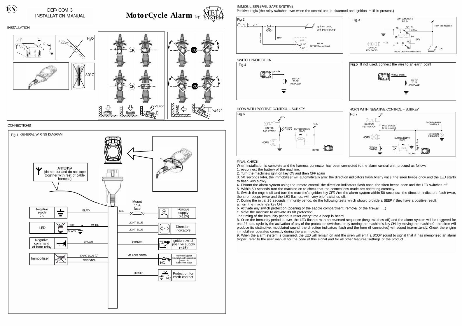
IMMOBILISER (FAIL SAFE SYSTEM)Positive Logic (the relay switches over when the central unit is disarmed and ignition +15 is present.)
SWITCH PROTECTION
HORN WITH POSITIVE CONTROL – SUBKEY HORN WITH NEGATIVE CONTROL – SUBKEY
Fig.5 If not used, connect the wire to an earth point
+12V
+12V
Fig.6 +12V
+12V
Fig.7
Fig.4
yellow/green
SWITCHTO BE
INSTALLED
SWITCHTO BE
INSTALLED
HORN
HORN
P600 DIODESto be installedORIGINAL
CONTROL
ORIGINALCONTROL
SUPPLEMENTARYRELAY
SUPPLEMENTARYRELAY
DIRECTIONINDICATORS
TO THE ORIGINALCONTROLS
IGNITION KEY SWITCH
IGNITION KEY SWITCH
FINAL CHECKWhen installation is complete and the harness connector has been connected to the alarm central unit, proceed as follows:1. re-connect the battery of the machine.2. Turn the machine’s ignition key ON and then OFF again3. 50 seconds later, the immobiliser will automatically arm: the direction indicators flash briefly once, the siren beeps once and the LED startsto flash very slowly.4. Disarm the alarm system using the remote control: the direction indicators flash once, the siren beeps once and the LED switches off.5. Within 50 seconds turn the machine on to check that the connections made are operating correctly.6. Switch the engine off and turn the machine’s ignition key OFF. Arm the alarm system within 50 seconds: the direction indicators flash twice,the siren beeps twice and the LED flashes, with very brief switches off.7. During the initial 26 seconds immunity period, do the following tests which should provide a BEEP if they have a positive result:a. Turn the machine’s key ON.b. Activate any switch protection (opening of the saddle compartment, removal of the firewall, …)c. Move the machine to activate its tilt protection.The timing of the immunity period is reset every time a beep is heard.8. Once the immunity period is over, the LED flashes with an reversed sequence (long switches off) and the alarm system will be triggered forone 26 sec. cycle by the activation of any of the protection switches, or by turning the machine’s key ON, by moving the machine0: the siren willproduce its distinctive, modulated sound, the direction indicators flash and the horn (if connected) will sound intermittently. Check the engineimmobiliser operates correctly during the alarm cycle.9. When the alarm system is disarmed, the LED will remain on and the siren will emit a BOOP sound to signal that it has memorised an alarmtrigger: refer to the user manual for the code of this signal and for all other features/settings of the product..
brownbrown
light
blu
e
purple
Fig.2
dark
blu
e
grey
RELAYDEF-COM central unit
Ignition pack,coil, petrol pump
NC
C
MotorCycle Alarm by
DEF•COM 3INSTALLATION MANUAL
INSTALLATION
EN
CONNECTIONS
Positivesupply (+12V)
Mount15Afuse
Direction indicators
Ignition switchpositive supply
(+15)
Negativecommand
of horn relay
Protection againstremoval of earth connection
(connect toearth if not used)
ANTENNA(do not cut and do not tapetogether with rest of cable
harness)
Protection forearth contactNO
LED
ImmobiliserNC
REDBLACK
BLACK
RED WHITE
PURPLE
LIGHT BLUE
LIGHT BLUE
ORANGEBROWN
DARK BLUE (C)
GREY (NO)
Negative supply
( - )
YELLOW/GREEN
Fig.1 GENERAL WIRING DIAGRAM
+
80°C
H2O
↕
<±45°>±45°↕
KO
KO
OK
OK
BLOCCHETTOCHIAVE
AVVIAMENTO
RELE'SUPPLEMENTAREFig.3
blu+ 15
30
85
87
87/A
86grey
NC
C
From the magneto
COILRELAY DEF-COM central unit
NO
NO
NCC
SUPPLEMENTARYRELAY
IGNITIONKEY SWITCH
MotorCycle Alarm byDEF•COM 3
OPERATION MANUAL
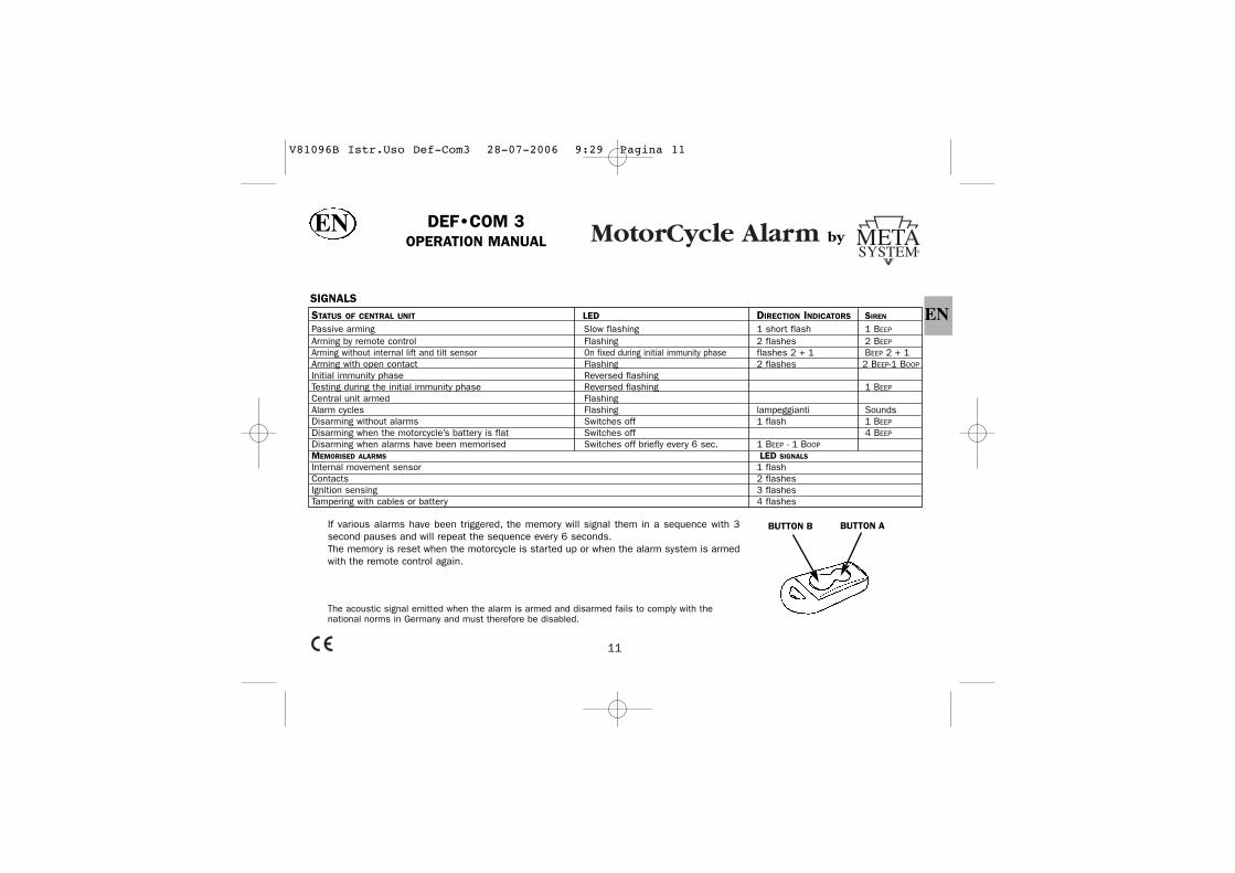
SIGNALS
If various alarms have been triggered, the memory will signal them in a sequence with 3second pauses and will repeat the sequence every 6 seconds.The memory is reset when the motorcycle is started up or when the alarm system is armedwith the remote control again.
The acoustic signal emitted when the alarm is armed and disarmed fails to comply with thenational norms in Germany and must therefore be disabled.
11
STATUS OF CENTRAL UNIT LED DIRECTION INDICATORS SIREN
Passive arming Slow flashing 1 short flash 1 BEEP
Arming by remote control Flashing 2 flashes 2 BEEP
Arming without internal lift and tilt sensor On fixed during initial immunity phase flashes 2 + 1 BEEP 2 + 1Arming with open contact Flashing 2 flashes 2 BEEP-1 BOOP
Initial immunity phase Reversed flashingTesting during the initial immunity phase Reversed flashing 1 BEEP
Central unit armed FlashingAlarm cycles Flashing lampeggianti SoundsDisarming without alarms Switches off 1 flash 1 BEEP
Disarming when the motorcycle’s battery is flat Switches off 4 BEEP
Disarming when alarms have been memorised Switches off briefly every 6 sec. 1 BEEP - 1 BOOP
MEMORISED ALARMS LED SIGNALS
Internal movement sensor 1 flashContacts 2 flashesIgnition sensing 3 flashesTampering with cables or battery 4 flashes
EN
EN
BUTTON B BUTTON A
V81096B Istr.Uso Def-Com3 28-07-2006 9:29 Pagina 11

PASSIVE ARMINGThe central unit arms automatically in 50 seconds:- After the motorcycle’s key has been turned OFF, or- After the remote control has been pressed to disarm the alarm system, or- After the alarm system has been disarmed using the ‘override’ code.The passive arming is signalled by a short flash of the direction indicators, by a BIP from the siren, the very slow flashing of the LED;only the engine immobiliser is armed. It is also possible to select the passive arming of all the alarm system (see the paragraph onconfiguration). In this case, the signals given are the same as those of arming using the remote control.
MANUAL ARMINGPress the button A of the remote control briefly within 50 seconds of turning the motorcycle’s ignition key OFF; the direction indicatorsflash twice and the siren emits 2 BEEP sounds. All the central unit’s functions have been activated and the LED is flashing.
ARMING WITHOUT ACTIVATING THE INTERNAL MOVEMENT SENSORPress the button A of the remote control for approximately 2 seconds and within 50 seconds of turning the motorcycle’s ignition keyOFF; the direction indicators flash 2 + 1 times and the siren emits 2 + 1 BEEP sounds. All the central unit’s functions have beenactivated except the movement sensor.The LED remains on without flashing for the initial immunity phase and then flashes normally.
DISARMINGPress the button A of the remote control briefly: the direction indicators flash once, the siren emits 1 BEEP sound and the LED switchesoff if no alarms have been triggered while the alarm system was active. If the LED remains on and the siren also emits a BOOP sound,this means that the alarm system was triggered. To find out how the alarm was triggered, consult the MEMORISED ALARMS table.
If visual and acoustic signals are given during arming or disarming that are different to those described above, consult the SIGNALStable to find out what they mean.
INITIAL IMMUNITY PHASEFor the first 26 seconds after the alarm system has been armed with the remote control, the LED flashes slowly to signal that it ispossible to test the protection functions of the system. Any alarm triggers do not provoke an alarm but just BEEP sounds by the sirentogether with the resetting of the initial immunity phase which starts again. When this phase is over, the LED reverses its flashingsequence (short switches on) and any alarm triggers will provoke an alarm.
ACTIVE PHASEThis is when the alarm system is armed and after the initial immunity phase is over. Any alarm triggers will provoke an alarm cycle thatlasts 26 seconds: the direction indicators flash, the siren, when connected, emits a distinctive, modulated sound the horn will soundintermittently and it will be impossible to start the engine.
12
EN
V81096B Istr.Uso Def-Com3 28-07-2006 9:29 Pagina 12
PROTECTION BY THE ALARM SYSTEMThe alarm central unit protects the motorcycle against being started and an alarm cycle will be triggered every time:- the ignition key is turned ON- an attempt is made to remove or move any part of the motorcycle which is protected by specific switches (for example if the seat orthe storage compartment is opened …- the motorcycle is moved- the alarm system’s supply cables are disconnected or cut or if the motorcycle’s battery is disconnected
STOP MODE – LIMITING CURRENT CONSUMPTION The alarm system automatically switches off in order to limit the consumption of current in the motorcycle’s battery, automaticallyexcluding the alarm functions but maintaining the immobilisation of the engine. In this condition current consumption is nil.STOP MODE is activated 5 days after the system was armed by remote control or automatically (passive arming) if no alarms weretriggered in this time;- If the motorcycle’s battery is almost flat.To exit STOP MODE, turn the ignition key ON: the siren will emit a series of BEEP sounds. Press the remote control within 5 seconds ofthe BEEPS to disarm the alarm system. If the remote control is not pressed within 5 seconds, an alarm cycle will be triggered.
EMERGENCY BLINKERThe Motorcycle’s Blinker can be armed by remote control.To arm, press button A on the remote control 2 times when the ignition key is in the ON position.To disarm, press button A on the remote control 1 time when the ignition key is in the ON position.
NB: When the Blinker has been armed by remote control and the ignition key is in the OFF position, the alarm can be armed: this willautomatically neutralise the internal lift and tilt sensor
PANICIt is possible to trigger a 10 second alarm cycle by pressing the B button on the remote control. This alarm cycle can be interrupted bypressing the same button again.
13
EN
V81096B Istr.Uso Def-Com3 28-07-2006 9:29 Pagina 13

SPECIAL FUNCTIONS – CONFIGURATIONIt is possible to set some alarm functions to adapt the alarm system to the motorcycle and its driver’s needs. To set the functions,which are described in the table below, proceed as follows:1. arm the alarm system with the remote control2. turn the ignition key ON within 10 seconds: the siren will make a BEEP sound to confirm selection 3. press the remote control’s button A briefly 4 times: the siren will make 4 BOOP sounds to confirm reception of the signal4. turn the motorcycle’s ignition key OFF5. turn the motorcycle’s ignition key ON and then OFF the same number of times as the number of the special function to be set (seetable). Leave the ignition key ON the last time: the LED is on6. briefly press the button A of the remote control once if the settings described in the first column are required (see table - BEEPcolumn)7. briefly press the button A of the remote control twice if the settings described in the second column are required (see table - BOOPcolumn)8. turn the ignition key OFF and briefly press the button of the remote control to exit programming mode, otherwise repeat from step 5to set another function.
FUNCTION BEEPYES NO
NO
NO
NO
YES
YES
YES
BOOP12345678
Buzzer when arming and disarmingDirection indicators when arming and disarmingHorn/siren alarm output or control of activation
Control of alternate horn or continuous siren Passive arming only of immoboliser or also alarm functionPassive arming with movement sensor enabled
Alarms of cyclical or single contacts
Allarm ActivationContinuous
Single
Also alarmAlternatedImmobiliser
CyclicalEnabling of automatic arming
14
TABLE SPECIAL FUNCTIONS – CONFIGURATION (factory settings in bold type )
EN
V81096B Istr.Uso Def-Com3 28-07-2006 9:29 Pagina 14

ON
X1 Alarm inactive
phase (after26 sec,)
ON
OFF
ON
A
ON
B
WITHIN 10 SEC.
OFF
WITHIN 10 SEC..
X1 X3
OFF
ON
C
WITHIN 10 SEC.
X2
OFF
ON
D
WITHIN 10 SEC.
X1
OFF
ON
E
WITHIN 10 SEC.
X2OFF
DisarmOK
WARNING: if 3 attempts to insert the wrong code are detected, the central unit will be blocked for 30 minutes in order to preventattempts to search for the code.
‘OVERRIDE’ EMERGENCY CODEIf a remote control is lost, stolen or damaged, it is possible to disarm the alarm system with a 5 digit emergency code called the‘OVERRIDE’ code. The code is found on the label supplied with the remote controls. This label must be kept in a safe place and not with the motorcycle.The procedure is operational only after the initial immunity phase is over, and if the alarm functions are operational, alarm cycles willbe triggered while the override code is inserted.
15
EN1 3 2 1 2
A B C D E1 3 2 1 2
‘OVERRIDE’EMERGENCY CODE
V81096B Istr.Uso Def-Com3 28-07-2006 9:29 Pagina 15

CUSTOMISING THE ‘OVERRIDE’ CODEIt is possible to customise the ‘override’ code so that it is easier to remember in case of emergency. Proceed as follows:
16
EN
OFF
X1
Within 3 sec.
ON
OFF
ON
A
ON
B
OFF
X1 X3
OFF
ON
C
WITHIN 10 SEC.WITHIN 10 SEC.WITHIN 10 SEC.
X2
OFF
ON
D
X1
OFF
ON
EX2
X3
Keep ON at thethird activation –
confirmationBeep
2 Beep2 Boop
2 Beep2 Boop
1 3 2 1 2
‘OVERRIDE’EMERGENCY CODE
WITHIN 10 SEC. WITHIN 10 SEC.
1 2 1 1 3
F G H I L1 2 1 1 3
EMERGENCY CODE"NEW OVERRIDE"
ON
F
ON
GX1
ON
IX1
OFFOFF
ON
L
CUSTOMISING
‘OVERRIDE’ CODE
X2
ON
X1 X3
3 SEC.PAUSE
3 SEC.PAUSE
3 SEC.PAUSE
3 SEC.PAUSE
WITHIN 10 SEC.WITHIN 10 SEC.WITHIN 10 SEC.WITHIN 10 SEC.WITHIN 10 SEC.
OFFOFF
OFF
OFF
H
A B C D E1 3 2 1 2
V81096B Istr.Uso Def-Com3 28-07-2006 9:29 Pagina 16
ADDITIONAL REMOTE CONTROLSThe alarm system is usually supplied with 2 remote controls, called nr. 1 and nr. 2.It is possible to check how many remote controls are programmed into the alarm system’s central unit every time the motorcycle isswitched off (i.e. when the ignition key is turned OFF): the LED flashes the same number of times as the number of remote controls.To add or remove remote controls from the memory, gather all the remote controls together that are to be included in the alarm system’smemory (new remote controls must be programmed at your dealer’s with the code on the red code-card that is supplied with theproduct) and proceed as follows:1. disarm the alarm system2. turn the ignition key ON for 3 times within 5 sec and keep it ON the last time (a BEEP sound confirms selection)3. turn the ignition key OFF within 5 sec and insert the ‘override’ code4. when the fifth digit is confirmed, keep the ignition key ON: a series of BEEP–BEEP-BOOP-BOOP sounds confirms the code was correct5. briefly press the button A of the remote control to be included: the LED flashes to confirm reception6. press the button A of the same remote control again: a BEEP sound the LED switching OFF confirms it has been memorised7. repeat steps 5 and 6 for all the remote controls to be included. Any remote controls that are not used (e.g. if lost) will be excluded.8. turn the ignition key OFF a series of BEEP–BEEP-BOOP-BOOP sounds confirms the end of the procedure and the LED flashes the samenumber of times as the number of included remote controls.
17
EN
RESTORING THE DEFAULT OVERRIDE CODEShould the driver forget or lose the override code for the product, the ‘11111’ default override code can be restored provided he has tworemote controls. Follow the procedure below to do this:Disarm the product using the remote control, turn the motorcycle’s ignition key to ON and press button A alternately on both remotecontrols twice. The siren confirms that the override code has been restored by means of its Beep-Beep-Boop-Boop sequence, and theLED then displays the code 11111. All the actions requiring use of the override code can now be completed since it has been confirmed.
V81096B Istr.Uso Def-Com3 28-07-2006 9:29 Pagina 17
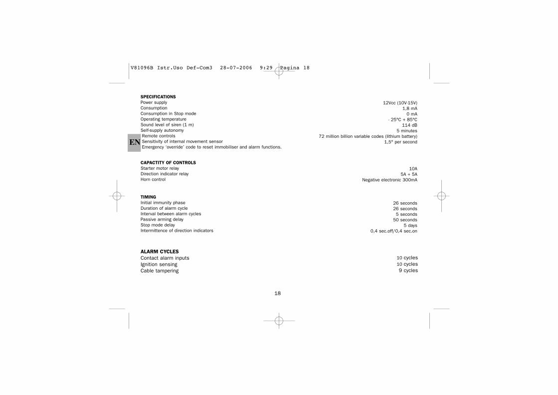
SPECIFICATIONSPower supplyConsumptionConsumption in Stop modeOperating temperatureSound level of siren (1 m)Self-supply autonomyRemote controlsSensitivity of internal movement sensorEmergency ‘override’ code to reset immobiliser and alarm functions.
12Vcc (10V-15V)1,8 mA
0 mA- 25°C + 85°C
114 dB5 minutes
72 million billion variable codes (lithium battery)1,5° per second
CAPACTITY OF CONTROLSStarter motor relayDirection indicator relayHorn control
10A5A + 5A
Negative electronic 300mA
TIMINGInitial immunity phaseDuration of alarm cycleInterval between alarm cyclesPassive arming delayStop mode delayIntermittence of direction indicators
26 seconds26 seconds5 seconds
50 seconds5 days
0,4 sec.off/0,4 sec.on
EN
18
ALARM CYCLESContact alarm inputsIgnition sensingCable tampering
10 cycles10 cycles9 cycles
V81096B Istr.Uso Def-Com3 28-07-2006 9:29 Pagina 18
19
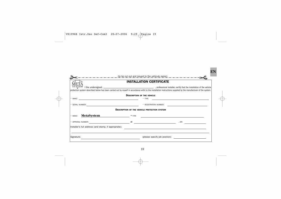
EN(to be cut out and issued to the vehicule owner)
INSTALLATION CERTIFICATE
I the undersigned, , professional installer, certify that the installation of the vehicleprotection system described below has been carried out by myself in accordance witht to the installation instructions supplied by the manufacturer of the system.
DESCRIPTION OF THE VEHICLE
• MAKE: • TYPE
• SERIAL NUMBER: • REGISTRATION NUMBER:
DESCRIPTION OF THE VEHICLE PROTECTION SYSTEM
• MAKE: MetaSystem • TYPE
• APPROVAL NUMBER: at , on
Installer’s full address (and stamp, if appropriate):
Signature: (please specify job position)
V81096B Istr.Uso Def-Com3 28-07-2006 9:29 Pagina 19