defense documentation center defense … · radio is not the only means of transmitting information...
TRANSCRIPT

UNCLASSIFIED
AD 637 134
POWER TRANSFER BETWEEN TWO ANTENNAS WITHSPECIAL REFERENCE TO POLARIZATION
Beuhring W. Pike
Air Force Systems CommandVandenberg Air Force Base, California
December 1965
Processed for...
DEFENSE DOCUMENTATION CENTERDEFENSE SUPPLY AGENCY
FOR FEDERAL SENTIC AND TECNAL INFORMATION
U. I. DhPARTMENT OF COIEAIdIII I NATIONAL IUpEAU Of STANDAR• I INSTITUTE FOEl APPLIEO TECHNOLOGY
UNCLASSIFIED

AFWTR-TR-65-1
POWER TRANSFER BETWEEN TWO ANTENNASWITH SPECIAL REFERENCE TO POLARIZATION
BEUHRING W. PIKE, P.E.
RANGE SYSTEMS ENGINEERING
TECHNICAL REPORT-NO. AFWTR-TR-65-L
DECEMBER 1965
t f t
AIR FORCE WESTERN TEST RANGEAIR FORCE SYSTEMS COMMAND
VANDENBERG AIR FORCE BASE, CALIFORNIA 93437

DOD DISTRIBUTION STATEMENT:
A. Distribution of this document is unlimited.
AVAILABILITY NOTICES:
A. Copies of this report may be procured from Office of Technical Services,
Department of Commerce, Washington, D.C.
B. Qualified requesters may obtain copies of this report from the Defense
Documentation Center (DDC), Cameron Station, Alexandria, Virginia 2Z314.
REPRODUCTION NOTICES:
A. This Technical Report may be reproduced in its entirety, but not in part
unless the partial reproduction carries a full identification of the source.
B. Extra copies of the two pages that carry Equation (1) and Equation (2)
through Equation (7) are included at the end of this paper. These trans-
lucent sheets can be removed, and may be utilized as master positives
for producing additional prints provided that each copy retains in the
margin the identification of the source.
DISPOSITION NOTICES:
A. If this copy is not needed, return it to Headquarters, Air Force Western
Test Range (WTSMR), Vandenberg Air Force Base, California 93437.I w
Ik•

POWER TRANSFER BETWEEN -TWO ANTENNAS
WITH SPECIAL REFERENCE TO POLARIZATION
by
BEUNRING I PIKE, P. E.
S( RANGE SYSTEMS ENGINEERING
Technical Report No. AFWTR-TR-65-1
December 1965
71
)/
/

FOREWORD
Radio is not the only means of transmitting information to or from a vehiclesuch as a spacecraft, but it is by far the most important. In many instances(particularly with rocket propelled vehicles) the information to be transmittedvia the radio link is, in terms of time and money, of great value; in some cases,where human life will be at risk, the information to be transmitted is of a valuebeyond price.
For these reasons one desires to be able to analyze a hypothetical radio linkand calculate the power that would be delivered to a radio receiver by the receiver'santenna. In order to make such calculations one needs to calculate first the free-space case and to then apply corrections to account for the effects of the mediumand its boundaries.
The literature abounds with guides for calculating the free-space powertransfer between two antennas having matched polarizations. However, literaturecovering the cases wherein the two antennas are not of matched polarizationsis scarce. For this reason, the following paper has been developed to providethe necessary equations in complete and convenient form. This paper providesalso methods of applying antenna radiation pattern representations to the solutionof the equations.
A subsidiary purpose of this paper is to point out the overwhelming importanceof polarization by showing that ever receiving antenna is completely "blind" tosome radio wave because the po lari-ation mismatch loss is infinitely large. Itis hoped that the proof given herein will result in greater application of means ofavoiding polarization mismatch losses - means such as Polarization DiversityReception (PDR) and Polarization Alternation of Transmissions (PAT).
This paper was begun in 1961 and nearly completed while the author wasemployed by the U. S. Navy as the Instrumentation Consultant of the RangeDevelopment Department of the Pacific Missile Range (Pt. Mugu, California)prior to his position being transferred to Air Force Western Test Range, Vanden-berg Air Fo-'ce Base, California in January, 1965. '*l
This paper, which evolved through more than thirteen draft versions,benefited from efforts of many people:
1. The technical content of this paper reached essentially its present formby August 1964; copies of that draft were given to several people, includingmembers of the Electronic Trajectory Measurements Working Group of theInter- Range Instrumentation Group.
.• ii
/,

FOREWORD (Cont'd)
1. The writer is indebted to the late MR. ROBERT F. BENTON (formerly SeniorTechnical Consultant of the Range Development Department of the PacificMissile Range) for making available the time for the early phases of thedevelopment of this paper, for encouragement, and for assistance on themathematics involved in the development of the equations for the polarizationmismatch loss where linearly polarized waves and/or antennas are involved.
2. Very early in the development of this paper, assistance was given the authorby DR. A. V. DONNELLY, (then PMR Staff Consultant; now teaching at ArizonaState University), by MR. LLOYD RITLAND (PMR Instrumentation Systems Division),and by MR. DWIGHT L. MCKEE (now of the PMR Electronics Development Division).
3. MR. GEORGE W. MORRIS, JR. (now of the Range Instrumentation PerformanceEvaluation Branch of the PMR Range Operations Department) assisted theauthor many times on the mathematical development (and made some of thecalculations).
4. MR. EUGENE M. FETNER (of the Air Force Eastern Test Range, Patrick AirForce Base, Florida) made major contributions to the development ofAppendix D (see reference 29, Acknowledgements)
5. The penultimate PMR manuscript draft of this paper was reviewed fortechnical accuracy (at the request of the author) by an ad hoc committeeestablished by DR. G. W. BRAUN, PMR Chief Scientist.
(. 1PMR Review Committee:
MR. WILLIAM A. BOWEN, JR., Technical Consultant, Chief Scientist's Office(Code 01-3).
MR. JERALD LEISH, Head, Command Guidance Branch (Code N322).
MR. GEORGE W. MORRIS, JR., Mathematician, Range Instrumentation Evaluation
Branch (Code 3274).
MR. CULLEN B. TENDICK, Head, Radio Branr. (Code 3161).
6. The author's final PMR typescript was reviewed by MR. M. M. MATSEN,Deputy PMR Range Development Officer, and by MR. K. I. LICHTI, Head,PMR Range Analysis and Planning Division (then Acting Deputy RangeDevelopment Officer), who both raised some mathematical questions andmade suggestions that were incorporated to improve the clarity of themathematical developments and the ease of access to the definitions ofsymbols and terms.
BEUHRING W. PIKE, P. E.(Calif. E-3994, Tex. E-5916)."B. S. in E. E., the Rice University, 1942.Senior Member, IEEE.Member, RESA. Member ETMWG of IRIG.
(4184 Arcturus Ave.,Lompoc, Calif., 93436)
iii
{ //

/
FOREWORD (Cont'd)
APPROVAL
This technical report has been riviewed and edited by the Scientific and TechnicalInformation Office, Air Force Western Test Range, Vandenberg Air Force Base,California, 93437.
Publication of this report does not constitute Air Force approval of the report'sfindings or conclusions. It is published only for the exchange and stimulationof ideas.
STANLE RADOM EK. SK /Technical Director ajor, USAF /AF Western Test Range Chief, Range Technical
Services BranchAF Western Test Range
iv

ABSTRACT
The literature abounds vith examples of a convenient equation ("the beaconequation") for .alculating the free-space power transfer between two widelyspaced radio antennas having polarizations that are matched for maximum powertransfer. On the other hand, convenient equations for making such calculationswhere Me polarizations are not matched are very scarce. In this paper the wellknown beacon equation has bi;ii combined with a published (but relatively littleknown) general equation for polarization mismatch loss, so as to yield a completegeneral equation for calculating the power transfer between two widely spacedantennas in free-space, For convenience, the portion of the general power transferequation that accounts for pclarizati .n mismatch loss has been reduced to yielda special equation for each of the five limiting cases. Also given are discussionsof polarization problems and solutions in radio and radar, and a discussion ofantenna radiation field representation methods ard their use in calculating thepower transfer between two antennas. This 75 pFge Techxdcal Report includes aGlossary of 125 terns and a Bibliography of 68 references.
DESCP.IPTORS FOR COORDINATE INDEXING
(The principal descriptors are underlined)
Aircraft Patterns
Antenna s Polarization
Bibliography Power Gain
Coupling Power Transfer
E dona P ropagation
IEEE Standard Radar
IRE Standard Radiation
IRIG 13tandard Radio
Magneto- Ionic SEacecraft
NOTE: Theso descriptors are not identical to 9imilardescriptor, used by Defense Documentation Center (DDC)
V
v/

l/
(This page is intentionally blank)
vi

( TABLE OF CONTENTS
4. Page
FOREWORD ............ . ............... 9-........... ii
APPROVAL STATEMENTS . ......... . ........ . . ..... iv
ABSTRACT .. . .. .. .. .. v
TABLE OF CONTENTS . see . . . . . ...... . ....... 9 v a.. . vii
INTRODUCTION ... . .... .se so ~ e sets tes o * I . . . . . . .
THE POWER TRANSFER EQUATION ....................... 4
SUBSIDIARY EQUATIONS FOR POLARIZATION MISMATCH ....... 5
APPENDIXES
A. POLARIZATION PROBLEMS IN RADIO AND RADAR ...... 7
1B. DEVELOPMENT OF THE POWER TRANSFER EQUATION ... 15
C. DEVELOPMENT OF POLARIZATION MISMATCHLOSS EQUATIONS . .. o . . . . . ....... .9......... 19
D. ANTFNNA RADIATION PATTERNS AND THEIR USE INDETERMINING VALUES NEEDED TO SOLVE THEPOWER TRANSFER EQUATION .................. 27
Figure Dl. Coordinate Systems . . . 0 . . .... . . . . 39Figure D2. Antenna Pattern Chart ........... 41Figure D3. Data Requirements Chart ......... 43
E. GLOSSARY OF SYMBOLS ANT TERMS ............... 45
REFERENCES AND BIBLIOGRAPHY ....................... 53
ERRATUM FOR REFERENCES ............ 58
INDEX . . .9 . . . . . . .. . . . 61
Extra Copies of Pages 4 and 5 (Removable and ReproducibleEquation Pages) . . . . . , ... . . .. 9 0 9 11 * 0 . . . . 0 . . .. ... 67
DD FORM 1473
V .n
[ 1 m1 m 1 m vii

)
(This page intentionally blank)
viii

INTRODUCTION
C> Readily found in the literature is an equation (sometimes called The Beacon'& Equation) for calculating the power transfer between two antennas of matched polar-
izations when the antennas are in free-space and in the far-field (the FraunhoferRegion) of one another. However, literature covering all the cases in which thepolarizations are not matched is relatively very scarce. *2
Most aircraft antennas and spacecraft antennas are rigidly fixed to the vehicle'sbody, and are required to have extremely broad angular coverage in order to pro-vide simultaneous coupling with many other antennas at separate remote locations(and/or to permit large angular movements of the vehicle). Because of this, nearlyevery vehicle antenna unavoidably has a free-space radiation field whose power gainiunction and polarization functions are extremely complex. For purposes of free-space power transfer calculations involving an antenna of this kind, one must obtain,from the power gain functions, the Power Gain of each of the two antennas in thedirection of the other. Also, one must calculate, from the polarization functions,the Polarization Mismatch Loss between the radio wave and the receiving antenna, ":43
This paper gives, in ready-reference form, a well known equation for calculatingthe free-space power transfer between two antennas when one knows the Frequency,the Distance between the antennas, the Power Gain of each of the antennas in thedirection of the other, the Polarization Mismatch Loss between the radio wave andthe receiving antenna, and any miscellaneous system losses (or gains).
In addition, this paper gives a published but relatively little known generalequation for calcrlating the free-space Polarization Mismatch Loss when one knowsA. the Ellipticity Ratio (including the "sense") of each of the two antennas, and B.M e Polarization Mismatch Angle between the polarization ellipses of the twoantennas.
For convenience, this Polarization Mismatch Loss equation is given also infive reduced forms covering the five special cases where one (or both) of theantennas is of a polarization that is a limiting case of elliptical polarization - thatis - circularly polarized, or linearly polarized. Although some of these reducedequation3 are well known, others are not. Since their derivation may not be obvious,the development of the five equations is given in Appendix C.
Z. The reader is invited to observe that most of the writers who give an equationfor power transfer between two antennas in free- space not only do not includea factor to account for polarization mismatch loss but also do not warn thereader that the equation is invalid for other than matched polarizations. Amongthose writers who do include a factor for the polarization mismatch loss, veryfew give an equatio'-for calculating the value of the polarization mismatch lossfactor.
*3, Because of the overwhelming importance of polarization in the transfer of power
"between two antennas, a general discussion, "Polarization Problems in RadioSand Radar" is given as the first appendix ý,f this paper.
.gvna4apni
- pper

INTRODUCTION (Cont'd)
Appendix C also contains a proof of the highly significant fact that under far-field or Fraunhofer Region conditions e receiving antenna is completely "blind"to some radio wave because the Polarization Mismatch Loss is infinitely large.
This proof is given to emphasize the importance of Polarization DiversityReception (PDR), wherein two orthogonally polarized receiving antennas each feedone of two independent receivers whose outputs are combined (or utilized inde-pendently) and of Polarization Alternation of Transmissions (PAT), wherein al-ternate Fulses (or pulse groups) have orthogonal polarizations.
The Power Transfer Equation given is for two antennae in free-space. Forantennas not in free-space, the equation can be used by including system losses andgains notaiready included (among these are those caused by multipath wave-interference, normal refraction, anomalous propagation, absorption by the medium,dispersion by the medium, scattering by objects, and diffraction over the horizon).The Polarization Mismatch Loss equations can be used for antennas not in free-space by taking into account any in-transit change of the wave polarization, such asis caused by reflection and by mal neto-ionic propagation.
It is the author's hope that this paper will help to bridge the hiatus that existstoday between theory and its application. Because of the critical importance ofthe subject of this paper, the author requests immediate notification of any errorsthat may be found herein.
This paper contains 125 symbols and terms, 17 of which have been coinedherein, and all of which are defined in Appendix E. Of the 68 references listed inthc "References and Bibliography" section, 32 are cited herein.
Throughout this paper each personal name (and the name of each organizationissuing an anonymous publication) is indicated thusly: A.U. TIoR.
• . I t m | I)

NOTE: This page is intentionally blank so thatEquation I will face Equations 2 through 7.
3
/
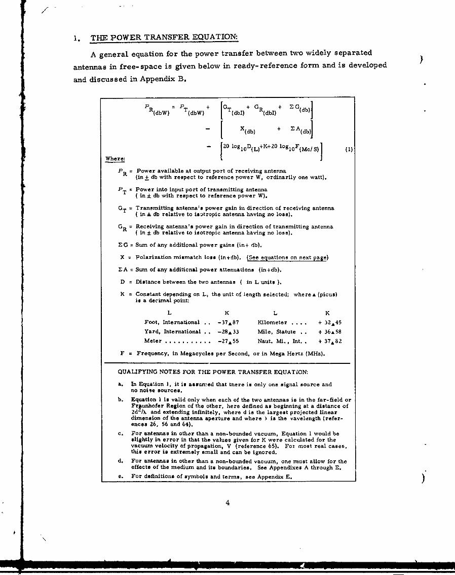
1. THE POWER TRANSFER EQUATION:
A general equation for the power transfer between two widely separated
antennas in free- space is given below in ready- reference form and is developed
and discussed in Appendix B.
PR(dbW) PT + G + GR + ZG(db)=dW + GT)(dbl) Gldi
- [ X(db) + ZA(db)]
Where -- [20 loglOD ()+K+2O logloF(Mc/s)] (S)
PR = Power available at output port of receiving antenna(in + db with respect to reference power W, ordinarily one watt).
PT = Power into input port of transmitting antenna(in ;L db with respect to reference power W).
GT = Transmitting antenna's power gain in direction of receiving antenna( in : db relative to isotropic antenna having no loss).
GR = Receiving antenna's power gain in direction of transmitting antenna( in : db relative to isotropic antenna having no loss).
Z• G = Sum of any additional power gains (in+ db).
X Polarization mismatch loss (in+db). (See equations on next page)
ZA= Sum of any additional power attenuations (in+db).
D = Distance between the two antennas ( in L units ).
K = Constant depending on L, the unit of length selected; where A (picus)is a decimal point:
L K L K
Foot, International -37&87 Kilometer . ... + 32A45
Yard, International . -28&33 Mile, Statute . . + 36A58
Meter ............. - 2 7 A 5 5 Naut. Mi., Int. . + 37,82
F = Frequency, in Megacycles per Second, or in Mega Hertz (MHz).
QUALIFYING NOTES FOR THE POWER TRANSFER EQUATION:
a. In Equation 1, it is assumed that tnere is only one signal source andno noiie sources.
b. Equation I is valid only when each of the two antennas is in the far-field orFriunhofer Region of the other, here defined as beginning at a distance of2d /X and extending infinitely, where d is the largest projected lineardimension of the antenna aperture and where ý is the vavelength (refer-ences 26, 56 and 64).
c. For antennas in other than a non-bounded vacuum, Equation I would beslightly in error in that the values given for K were calculated for thevacuum velocity of propagation, V (reference 65). For most real cases,this error is extremely small and can be ignored.
d. For antennas in other than a non-bounded vacuum, one must allow for the
effects of the medium and its boundaries. See Appendixes A through E.e. For definitions of symbols and terms, see Appendix E. )
4
\A

la. POLARIZATION MISMATCH LOSS (X).
Equations for calculating the Polarization Mismatch Loss between two widely
(. separated antennas in free-space are given below in ready-reference form and are
developed and discussed in Appendix C.
Case:
(Polar-izationh) X = Polarization Mismatch Loss (in+db) =
Ellip. _JiJio,0io +t[ V_(o (2- -R + (1- T) (l -r Z) (C o on 2 P )
T --
Elni. (1•°I+r Y (1i)(2
ERltp.
4--rc _(1 lOglo 1rE) (Coo (irn. L(1+ r 1) (3)
®E
4-4 -10 logl o + C ELin. L L zJ (5)
Lin.
Lin. 0 olog 1 0o 1011 + +3 dbC(•c. (6)
CLrc4--+ -101ogfo +½ TCC RC4 0 -~10 1''o I rTc rRCI 0(cb When rT - rR
Circ. =+ odb When rTC= - rRC (7)
Where*4: r = Ellipticity Ratio, the signed voltage ratio of the major axis ofthe polarization ellipse to its minor axis, where (6-1 <ri <o).O'5
= Polarization Mismatch Angle, (00 :5 900). *5
T means Transmitting; R means Receiving.
E means Elliptically Polarized; C means Circularly Polarized.
*4: For definitions see Appendix E, Glossary of Symbols and Terms.
*5: See Appendixes A through E.
r. -
gc- 5
.J/

/
(This page is intentionally blank)
)

APPENDIX A
POLARIZATION PROBLEMS IN RADIO AND RADAR
A 1. THEOREM: For every radio antenna that feeds a single receiver (for every
receiving antenna having a single output port), there can be incident upon the
antenna a radio wave of a polarization orthogonal to that of the receiver's antenna
such that crne polarization mismextch loss is infinitely large, and the antenna there-
fore delivers to the receiver none of the energy of the incident wave. On the other
hand, when the polarization match is optimum the polarization mismatch loss is
zero. This theorem is proved in Appendix C.
AZ. RADIATION OF RADIO WAVES BY SPACE VEHICLES AND AIRBORNE
VEHICLES. In the general case, a radio wave radiated from a space vehicle or an
airborne vehicle is an extremely complicated wave whose intensity and polarization
vary greatly as a funct" :n of the direction from the vehicle. This is true both for a
radio wave scattered by a vehicle as an echoing radar target and for the wave
radiated by a fixed antenna on a vehicle.
a. In the general case, any object upon which a radio wave impinges
radiates (by scattering) a secondary radio wave whose intensity and polarization
both vary greatly as functions of the direction from the object. Any wave energy
scattered back to the antenna from which the incident wave came will (in the general
case) have a po.arization such that a component of the wave is of a polarization
r-rthogonal to that of the antenna that radiated the primary wave. In some instances,
Lhis orthogonal component is the only component present in the back-scattered wave.
b. A vehicle's radio transmitting antenna having a radiation field that is
fixed with respect to the vehicle radiates a wave whose intensity and polarization
both ... ry greatly as functions of the direction from the vehicle. In the general case,
wherever the vehicle's radio wave impinges upon any other antenna, the incident
wave hao a polarization such that a component of the wave is of a polarization ortho-
gonal to the pol-arization of the antenna upon which the wave impinges.
7

A3. RECEPTION OF RADIO WAVES RADIATED FROM VEHICLES.
a. When the antenna upon which a radio wave impinges is intended for
extracting energy from the wave and delivering it to a radio receiver, any wave
component that is of the same polarization as the polarization of the antenna is
accepted, but any wave component that is of a polarization orthogonal to the polar-
ivation of the antenna is totally rejected. That is, the Polarization Mismatch Loss 4-
is infinitely great.
b. In the general case, a radio wave coming from a vehicle to a receiving
antenna site, can, at that site, be of any polarization whatever (and can vary in
polarization as the vehicle moves). The ONLY way to insure that none of the energy
that is available in the wave incident on the receiving aperture is rejected and lost,
through polarization mismatch, is to provide Polarization Diversity Reception (PDR).
PDR is accomplished by having two orthogonally polarized receiving antennas, each
feeding one of two separate receivers whose outputs are combined (or utilized
separately). Note that both of the two orthogonally polarized antennas can be served
by the same lens, horn, or parabolic reflector for increasing the power gain of the
antenna in one direction (at the expense of another).
A4. RECEPTION BY VEHICLES OF RADIO WAVES.
The principle of reciprocity between antennas indicates that for a vehicle's receivi,.g
antenna having characteristics as described in paragraph A~b above, there can be,
for every direction from the vehicle, some incident radio wave whose polarization
is orthogonal to that of the vehicle's antenna in that direction such that the vehicle's
antenna delivers to its receiver none of the energy of the incident wave.
a. This vehicle antenna Polarization Mismatch Loss problem can, in
principle, be solved by applying PDR. However, it is very difficult to provide
two vehicle antennas having both a broad angular coverage and orthogonal polariza-
tions in every direction covered. In addition, there is the problem of providing a
second receiver (and possibly an output combiner).
(1) For pulse systems only, an alternate method that is almost as good
as PDR is Polarization Alternation of Transmissions (PAT), wherein the trans-
mitting antenna radiates pulses (or pulse groups) that alternate between two orthogonal
L i I I •' I I I I i I I I I H I

polarizations. Note that when PAT is used, the pulse repetition frequency should
be high enough to provide adequate system performance even under the condition
( where one of the two wave-polarizations happens to be exactly orthogonal to the
polarization of the receiving antenna.
(2) For continuous-wave systems, a similar thing can be done by having
two orthogonally polarized waves transmitted on slightly different frequencies and
by having two combined-output receivers fed from the same antenna. Here it is
important that the receiving antenna's characteristics be essentially the same, as
regards polarization, at both of the frequencies. This method can be called Polar-
iza'.ion Frequency Diversity (PFD).
A5. PULSE RADAR SYSTEMS FOR ECHO TRACKING OF VEHICLES.
a. With conventional echo tracking radars, much of the transmitted wave
energy that could be received as echo energy is not captured.
(1) An echoing target, in the general c"se, scatters back to the radar a
wave whose intensity ia a function of both the intensity and the polarization of thewave incident upon the target. For an extreme example, a thin short-circuited
dipole parallel to the electric field vector of a linearly polarized wave intercepts
and scatters much energy; the same dipole when perpendicular to the electric field
vector intercepts and scatters essentially no energy. The probability of such aneffect causing a long-duration null in the intensity of the wave scattered back from
a moving vehicle can be reduced by alternating the polarization of the radar's trans-mitted pulses (or pulse-groups) between two orthogonal polarizations (say Linear-
Horizontal and Linear- "Vertical"). This method, called PAT, has another advantage
with racons (radar beacons), as is described below in paragraph A6.
(2) An echoing target, in the general case, not only scatters the incident
wave but also transforms the polarization of the wave such that some (or all) of the
energy in the return wave at a conventional radar's receiving antenna is of a polar-ization orthogonal to the polarization of the radar's receiving antenna. *6, *7, `8 The
"*6 H. GENT, et al. (reference 19).( *7 G.E. Co. (reference 18).*;8 J.R. COPELAND (reference 11).
9

/
orthogonal component is rejected by the radar's receiving antenna. This waste of
extremely expensive energy can be avoided by employing PDR as described in
paragraph A3b.
(3) A pulse method only slightly less effective than dual-receiver PDR
is to have a single receiver whose input is commutated between the outputs of the
two orthogonally polarized antennas on an alternating, time-sharing basis. This
method can be called Polarization Alternation Reception (PAR).
b. It should be noted that most of the publications that give an equation for
"Radar Range" do not take into account the loss caused by a mismatch between the
polarization of the receiving antenna and the polarization of the back-scattered wave
arriving at that antenna. Consider, for example, the calculation of the tracking
range of a single-sense (Left-Handed, or Right-Handed)'" 9 circularly polarized
radar on an echoing target that is an essentially perfect "polarization mirror"
(a large flat platL of metal, a large three-sided corner-reflector of metal or a large
metal sphere). In the limit, the wave reflected (scattered) back to the receiving
antenna is circularly polarized in the opposite sense so that the Polarization Mis-
match Loss is infinitely lazge and the tracking range is therefore zero. It should
be noted also that the "Scattering Cross Section" of an echoing target (needed in the
Radar Range Equation for determining the amount of energy scattered back toward
the radar's receiving antenna) is (except in the case of a perfect homogeneous
sphere) a function of both the direction from the target to the radar and the polariza-
tion o f the wave incident upon the target. Trerefore, wave polarization must be
taken into account not only at the receiving antenna, but also at the echoing target. * 10
c. Although PAT and PDR (or PAR) in an echo-tracking pulse radar each
have some advantages, the simultaneous application of PAT with PDR provides the
best possible avoidance of polarization losses (and PAT with PAR is nearly as good).
See, in Appendix E, Sense; of an electromagnetic wave (or an antenna).
For an example of a Radar Range Equation that does include a polarizationfactor, see DONALD E. KERR (reference 33). )
10

A6. PULSE RADAR SYSTEMS FOR RACON (RADAR BEACON) TRACKING.
a. Unlike a wave scattered by an object in a radar beam, the intensity
and polarization of the wave transmitted by a racon have essentially no correlation
to the intensity and polarization of the incident wave from the radar. For this
reason it is even more desirable to provide PDR (or PAR) in a racon-tracking radar
than it is in an echo-tracking radar.
b. Similarly, as discussed in paragraph A4, there is only an imperfect
correlation between the polarization of the incident wave from a radar and the
polarization of the racon's receiving antenna in the direction of the radar. The
resulting Polarization Mismatch Loss can be reduced by applying PDR (or PAR)
at the racon. However, the diificulty of doing this with a vehicle racon is such that
it will be preferable in most cases to apply PAT (which is nearly as good for this
purpose).
c. With a pulse radar/ racon system there is another method of solving the
racon antenna problem. In this method the space vehicle or airborne vehicle carry-
ing the racon is equipped with a multiplicity of racon antennas having complementary
radiation patterns (complementary as to the directions of their intensity nulls and
orthogonal as to their polarizations in each direction), each feeding a separate
receiver. The outputs of the receivers are used to trigger the racon's reply and,
during the delay before the response, to switch the racon's transmitter to the antenna
that had delivered the most energy to a receiver. By the principle of reciprocity
between receiving and transmitting antennas, that antenna is the most favorable one
for transmicting the racon's reply to the interrogating radar. This method can be
called Reply Antenna Selection (RAS). For other racon diversity methods, see
Paragraph C-2 of reference 30.
d. It should be noted that most of the publications that give "Raccn (Beacon)
Range" equations do not take into account the loss caused by a mismatch between the
polaL.zation of the receiving antenma and the polarization of the wave incident or.
that antenna.
(
11

A7. For general information about racons (radar beacons), see A. ROBERTS,
Radar Beacons (reference 50) and IRIG System Standards for C-Band (5 cm)
Instrumentation Radars and Beacons (reference 30). For recent boo-ks on the
analysis of radar and racon systems, see BARTON 1 1 and SKOLMK "1. For recent
books regarding antenna considerations, see SPANOENSERO and HANSEN *14
A8. For tracking instrumentation radars with PAT and PDR features (for which
radars this author wrote the performance specifications), see Bureau of Naval
Weapons contract NOw 64-0620, with Sperry Gyroscope Co., Great Neck, N.Y.,
for four AN/ FPQ- 10-(XN- 1) radars, to be installed at Pacific Missile Range. The
most modern previous range instrumentation radar, the AN/ FPQ-6 (and its trans-
-portable version AN/TPQ-18) does not incorporate I-AT and PDR (or PAR). How-
ever, the operator can select either (I), a linear "vertical" polarization mode, or
(II), a circular pola rization mode in which the radar transmits left-handed circularly
polarized (LHCP) waves but receives right-handed circularly p2olarized (RHCP)
waves . Mode (II) provides an improvement in echo tracking of some targets.
For racon tracking, the mode option enables the radar operator to switch the polar-
DAvIoK. BARTON (reference 4). NOTE: After hia book was already in galley-
proof form, Barton added (on Page 132) a brief reference to this paper, as itwas then planned to be published by Pacific Missile Range.
*12 MERRILL I. SKoL041K (reference 58). See particularly Chapter 7, "Antennas".
K'3i..R. SeANGoENBeR, Editor (reference 59). On page 37, T.H. LEE pOintsout that polarization loss is not inctuded in •he radar range equation derived.On pages 65-67, J.L. BE,.Amy discusses polarization mismatch losses in theracon range equation given, but does not give an equation for calculating thoselosses, Note, on page 21, that the definition of "sense" given by A.S. DUNBsAis the definition used by most physicists and is opposite to that given by IRE(neYV IEEE). See "Sense" in Appendix E hereto.
'14 R.C. HANSEN (reference 20). Volume I of II was sighted but Volume II
was not available.
",15 The AN/ FPQ-6 (AN/TPQ-18) instruction manual does not make clear which
definition of '"sense" is intended. M.R. PAGLIEf, of the Radio Corporation ofAmerica, advised the author that the one used in the IRE (IEEE) definition. 4
)_12

ization so as to avoid the infinite polarization mismatch loss that occurs when the
beacon's antenna (wave) polarization becomes either (A), for Mode (I), linear-
horizontal, or (B), for Mode (11), circular (either LHCP or RHCP). Although this
polarization flexibility is very useful to a highly skilled operator, the combination
of PAT with PDR (or PAR) is much more effective because it is completely auto-
matic and, in some instances, can produce smaller polarization mismatch losses.
A9. WARNING: Sometimes a tracking radar not having PDR (or PAR) will track
with a side lobe of the antenna and refuse to track with the main lobe, thereby
introducing a large (and usually unsuspected) angle error. Such a condition can
occur when the polarization of the return wave becomes exactly orthogonal to that
of the main lobe, but the polarization of a side lobe is at least slightly different.
from that of the main lobe (which is almost always the cash. See SAMUEL SILVEF
(reference 56), page 423, regarding cross-polarization it, side lobes; see
R.C. HANSEN, (reference 20), pages 144 and 152, and A. ROBERTS (reference 50),
page 57.
A10. CAUTION: Ordinarily, the angle measuring accuracy of a high-accuracy
tracking radar such as the AN/ FPQ-6 (ANl TPQ-18) is a function of the polarization
of the wave being received such that polarizttions other than optimum (usual in
racon tracking) can produce angle errors that are many times the rated inaccuracy
of the radar. This problem can be solved by incorporating PDR in the radar. The
radar then receives predominately the polarizatic-i giving the better signal-to-noise
ratio and therefore automatically discriminates against the cross-polarized compo-
nent that causes the gross angle errors.
13

)
(This page is intentionally blank)
14

APPENDIX B
DEVELOPMENT OF POWER TRANSFER EQUATION
In a nonbounded vacuum, the fraction of the radio frequency power fed into
the input port of a transmitting antenna that is available from the output port of a
receiving antenna having its polarization matched to that of the radio wave (and
located at a distance sufficiently great that each antenna is within the far-field or
Fraunhofer Region of the other) can be determined from the beacon (racon) equation
derived by H.H. BAILEY in Radar Beacons (reference 50).16 This equation, with
the ratio of velocity to frequency (V/f) substituted for wavelength (X), is
S(V/41T)• •2 Yl1
2 1 fl 2 D(2
where1 7
*:€18
2 = Power available from receiving antenna's output port
= Power fed into transmitting antenna's input port * 18
V = Velocity of the radio wave (of light) in a nonbounded vacuum. TheUnion Radioscientifique Internationale (URSI) value is: 299,792L5i'±04"km/sec. (reference 65)
= 3A14159
1 = Power gain factor *18 of transmitting antenna in direction of receivingantenna, with respect to that of an isotropic radiator with no loss
"For a fundamental derivation of this equation, see also BERNARD M. OLIVER(reference 44), (NOTE: Neither Dr. Bailey nor Dr. Oliver give an equationfor calculating the power transfer for cases in which the polarizations are notmatched.)
17 See Appendix E for definitions of the symbols and terms used in this paper.
*: 18Note: The port at which the power gain is measured must be defined and
only that port must be referred tr in subsequent calculations.Note that the power gain factor is not expressed in decibels.
(
15
I /
/
= Power gain factor of receiving antenna in direction of trans-2 mitting antenna, with respect to that of an Isotropic radiator with
no loss
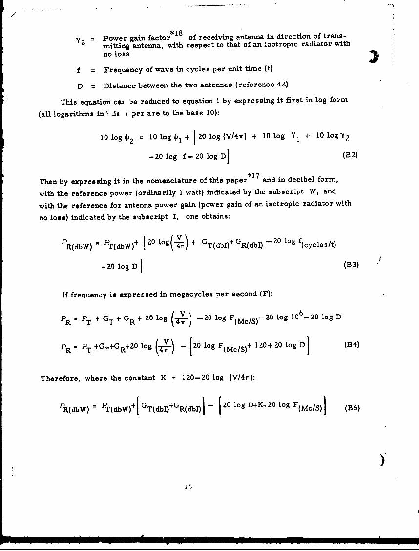
f Frequency of wave in cycles per unit time (t)
D = Distance between the two antennas (reference 42)
This equation caw ýe reduced to equation 1 by expressing it first in log for-m
(all logarithms in '..iu . per are to the base 10):
0logi 2 = 10 logi 1 + 1201og(V/47r) + 10log Yi + 10 logY 2
- 20 log f- 20 log DI (B2)
Then by expressing it in the nomenclature of thl.s paper* 17 and in decibel form,
with the reference power (ordinarily 1 watt) indicated by the subscript W, and
with the reference for antenna power gain (power gain of an isotropic radiator with
no loss) indicated by the subscript I, one obtains:
-R + 1 log(- V G+ G - 20 log fR(rlbW) T(dbW) , \r, GTdb) R(dbl) (cycle sit)
-2) log D (B3)
If frequency is exprecsed in megacycles per second (F):
P+ GT+ G+ 20 log -20 log F(McIS) log 106_-20 log DPR=P T + R (TT 20c) 2o0"•-
pR= PT +GT+GR+0 log I(V ) - 20 log F(Mc/S)+ 120+ 20 log Dl (B4)
Therefore, where the constant K = 120-20 log (V4•r):
PR(dbW) T(dbW)+ GT(dbI)+GR(dbI)j - 120 log D+K+20 log F(Mc/S)l (B5)
)-
16

\
Inserting terms for the polarization mismatch loss (X), additional power
attenuations (A), and any additional power gains (G) into equation B5 gives:
PR(dbW) = PT(dbW) + [GT(dbI) + GR(dbI) + IGldb)]
-4 X(db) + 'A(db)
-[20 log 10 D+K+20 log1 0 F(Mc/S)J (B6)
Which is equation 1, the power transfer equation for two antennas each in the
far-field (Fraunhofer Region *1 9 ) of the other.) 2 0 1 *21, *22, *23
*19 For a discussion of field regions, see SAMUEL SILVER (reference 56) and
U.S. AiR FORCE, Handbook of Radio Freguencý Radiation Hazards (reference64). The U.S. NAVY, BUREAU of NAVAL WEAPONS, has a similar (but confidential) radiofrequency hazards manual. Also see the forchcoming revised version ofreference 26.
*20 Many authors do not mention Polarization Mismatch Loss (X). The writer
suspects that one of the assumptions stated by SAMUEL SILVER on page 3of Reference (56) has been forgotten--Dr. Silver said, regarding the antennaas a receiving device: "In specifying the performance of an antenna, weshall supposa that the polarization of the wave and the impedance character-istics of th( dtp4rtnr are such that maximum power is absorbed".
*21 See page 3 of L. THOUREL (reference 62).
*22 See pages 436 and 438 of F.E. TERMAN and J.M. PETTIT (reference 61).
*23 A convenient relation pointed out on page 33-3 of reference 32 is that the
power attenuation between two lossless isotropic antennas of matched polar-izations, one wavelength apart in free-space, would be 22 db (and that forevery doubling of the separation, the attenuation is increased by 6 db).
17
i/

(This page is intentionally blank)
)-18

APPENDIX C
DEVELOPMENT OF POLARIZATION MISMATCH LOSS EQUATIONS
Significance of Polarization Mismatch
The polarization of an antenna in a given direction from the antenna is
defined as the polarization of the far-field (Fraunhofer Region) wave that would be
radiated in that direction by the antenna in free-space. The importance of matching
the polarization of a receiving antenna to the polarization of the radio wave to be
received is shown by the following theorem (which is proved in this appendix).
THEOREM: For every radio antenna that feeds a single receiver (for every
receiving antenna that has a single output port), there can be incident upon theS * 24
antenna a radio wave of a polarization orthogonal to that of the receiver's
antenna such that the polarization mismatch loss is infinitely large, and the antenna
therefore delivers to the receiver none of the energy of the incident wave. On the
other hand, when the polarization match is optimum, the polarization mismatch
loss is zero.
Calculation of Polarization Mismatch Loss (PML)
The polarization mismatch loss can be calculated from one of equations 2
through 7. For the general case, as expressed by equation 2, the following values
are needed:
1. Ellipticity ratio *5 (which includes the sense) of the wave radiated by
the transmitting antenna, here called rTT where [(1 -S rTI 5041'
Z4 In this paper, "orthogonal" means no• only "at 900°1 but also means, forelliptical polarizations and for circular polarizations, "of opposite sensesand of the same degree of ellipticity" (i. e. r - rT and, if determinate,
S=90°).
*25 See Appendix D for methods of determining, and Appendix E for definitions
of the symbols and terms used in this paper.
19

/
2. Ellipticity ratio*25 (which includes the sense) of the wave that would be
radiated by the receiving antenna if it were used for transmitting, here called rR,
where [(15 1 rRIOO)I
3. Polarization mismatch angle 25 between the major axes of the polar-
ization ellipses of the two-waves, here called P, (00 < < 900).
Less data are needed for special cases, where either (or both) of the antennas
is linearly polarized or circularly polarized (limiting cases of elliptical polarization),
as indicated by equations 3 through 7.
Development of Polarization Mismatch Loss Equation 2
The subject of the reception of elliptically polarized waves with elliptically
polarized antennas has been treated by several writers. See W. SICHAK AND S. MILAZZO
(reference 55), LEONARD HATKIN (reference 2Z), and V. H. RumnseY et al (reference 51).
Dr. Hatkin has presented the following equation (in which "4i* has been sub-
stituted for Hatkin's "P"):
ýRec. [4 2r 1 r 2 +(- r 1 ) (1- r 2 2) cos 2a
SOpt. ( (1+r 2Z) (O+r 2 2) Z(11+r, 2) (1+ r 22 ) I (C1)
Where ýRec. is the power available from a lossless receiving antenna of
arbitrary power gain and polarization, where opt. is the power available from
a lossless receiving antenna of the same power gain but whose polarization is
matched to the polarization of the incident radio wave, where r is the absolute
value of the "axial ratio", and where the minus sign is used when the "senses"
are opposite.
Replacing r 1 and r 2 with r T and r R (where 1(1 :51 r I s such thatthe "sense" of the wave is indicated by the sign of r), substituting f for Hatkin's
a (in order to agree with reference 29) and rearranging gives:
ýRec. = + 4r r R (cT)(- p(os2PýRet. (1 + r T) (l + r 2 (C2)
)20
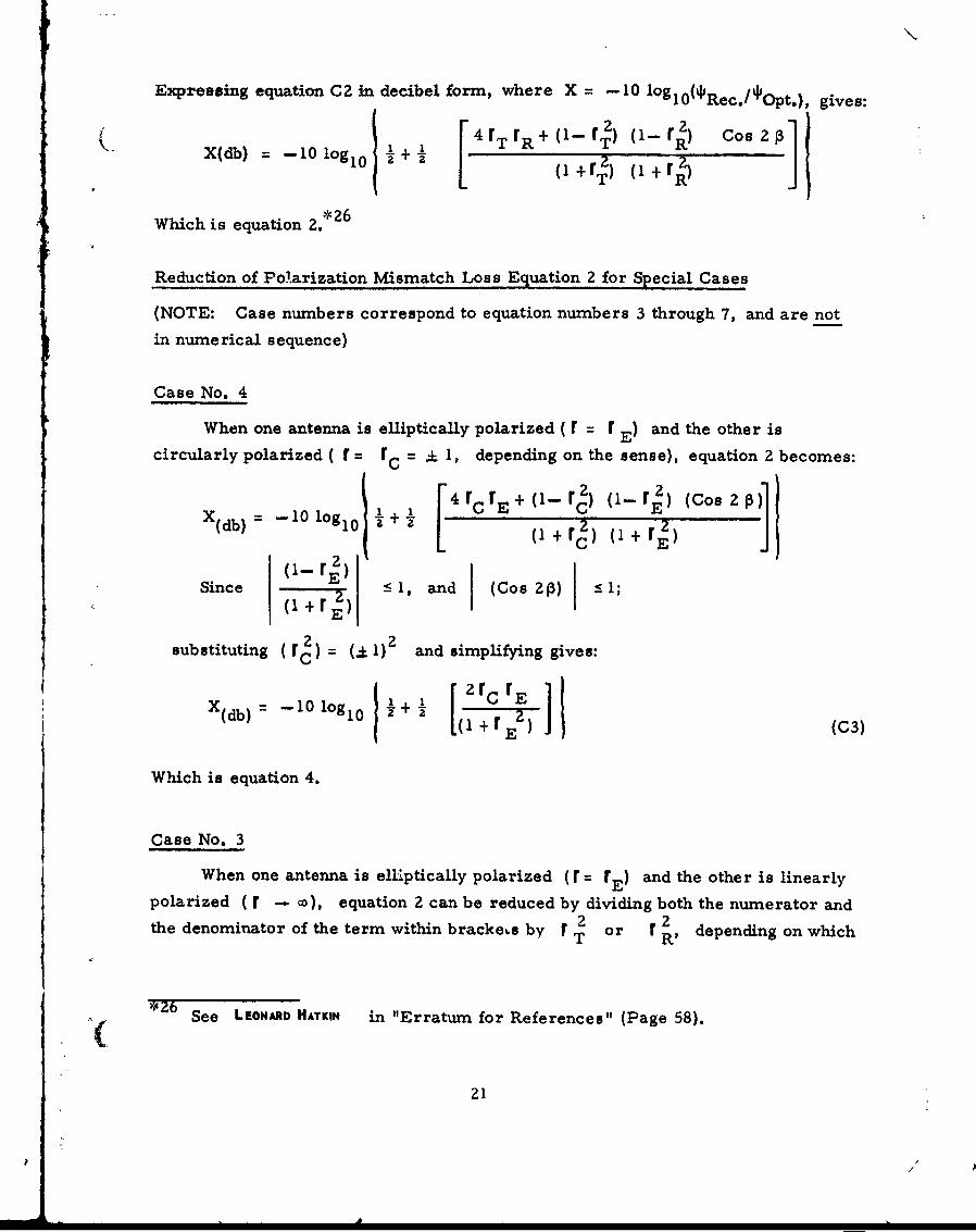
Expressing equation C2 in decibel form, where X = -10 oieOs:Rec./ Opt.),
4 r + (- r - rj) CoX(db) = -10 lOg 1O 0 + [ +rT) r+ T"R]
T R
Which is equation 2.*26
Reduction of Polarization Mismatch Loss Equation 2 for Special Cases
(NOTE: Case numbers correspond to equation numbers 3 through 7, and are not
in numerical sequence)
Case No. 4
When one antenna is elliptically polarized ( r = r E) and the other is
circularly polarized ( r = r 0 = C . 1, depending on the sense), equation 2 becomes:
[ rr r+(1- 1) o-r.) (Cos2
Since -< 1 and (Cos 2P) < 1;(1 + r )(rE)
substituting (r1 ) = (.- 1)2 and simplifying gives:
X(db) = -10 log1 0 j r (C3)
Which is equation 4.
Case No. 3
When one antenna is elliptically polarized (r = rE) and the other is linearly
polarized ( --- cw), equation 2 can be reduced by dividing both the numerator and
the denominator of the term within bracke~s by r T or r 2 depending on which
4Z6 See LEONARD HATKIN in "Erratum for References" (Page 58).
21p * (

7
antenna is linearly polarized, and then by taking the limit of X as r of the linearlypolarized antenna ( r L) becomes infinite. Assuming that rE r R and dividing by
r 2 gives:rT
4- + F-- r R) (Cos Z
Xrn = -2-10 [0g0
-b 1 1010 + + (0-1) (1-- r
lira X = --10 lOgl0 ½ + R)
rycL (o+1) (+ rR)
X -10 log1 R~)(Cs2)X(db) =-1lg0½-½(1+ r) 21C4)
Substituting rE for rR gives:
Xldb) 10-I logl ½- (1 + r) ,2
Which is equation 3.
Case No. 5
When both antennas are linearly polarized, dividing the numerator and
denominator of the term within brackets in equation C4 by rR and then taking the
limit of X as rR becomes infinite gives:,
(r'ff-2 (C os 213 1)S1IR
1)
lira x : -1o loglo ) - (
r- (0+1)
Xdb) = - lOglo + f Cos 2
(d) (CS)
22
p, pm m ,,~ mJJqlmJJ• l l

Which is equation 5. Since (½+ ½ Cos 2) Cos it can be written as:
-(db) = -10 log Cos 13 (C5A)
or as:
X(db) = -20 lOgl0 Cos ,8 (C5B)
Case No. 6
When one of the two antennas is linearly polarized and the other is circularly
polarized ( r = 1i), replacing rE by -1 or +1 in equation 3, which is
(1-(ros)2(3)S1X(db) -10 log1 0 E J
Gives
X(db) = -10 og 1 0 ½ +3db (C6)
Which is equation 6.
Case No. 7
When both antennas are circularly polarized ( 1T r TC = ± 1, and
rR = rRC =,j 1) equation 2 becomes:f4 r r + (i-r 2 (1- r ) (Cos 2•
1 [4TCrRC+ C RC(db)= -1-0 log10 ½ + ½ TlRrTC) -rR(C) C1J,( +rTC) (1RC)
Xldb) = -10 logl0 o- + [X(db) = -10 logl 0 ½+½ [rTc rRcJ (C7)
Which is equation 7.
23
/
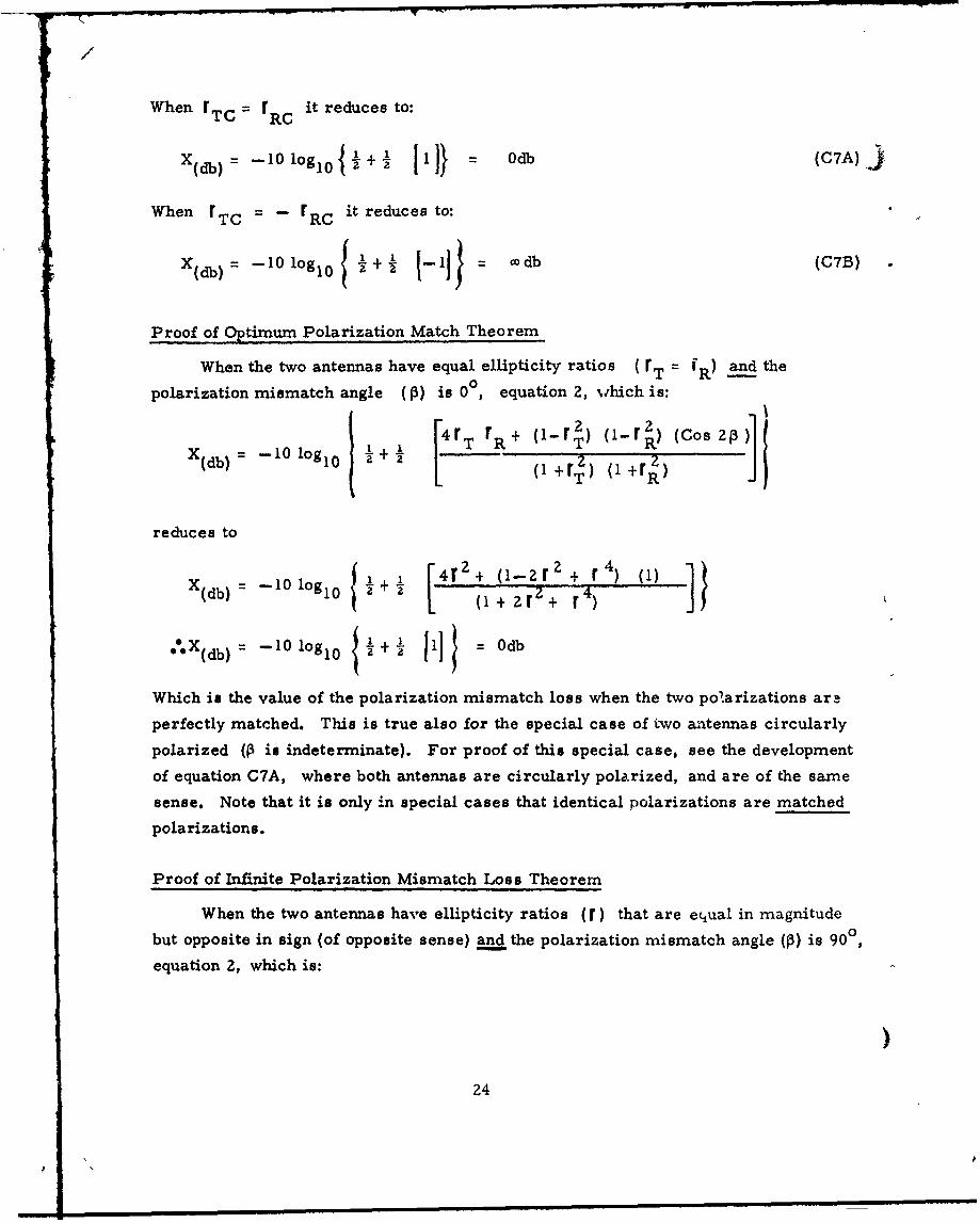
When rTC r RC it reduces to:
X d)~1loglo{!+.! Ii} db (C7A)j
When rTC - rRC it reduces to:
X.b) -1 1codb (C7B)
Proof of Optimum Polarization Match Theorem
When the two antennas have equal ellipticity ratios (rT = and the
polarization mismatch angle (3) is 00, equation 2, which is:
[4 r rR+ (1-r2) oi-r ) (cos 2)]X(db) = -- 10 logl 0 + (1 + r) (i +rR)
reduces to
X(db) =--10 lg 10 + [4r 2 + (-2 () + 4
='X~b -10 log10i+o d
Which is the value of the polarization mismatch loss when the two polarizations ara
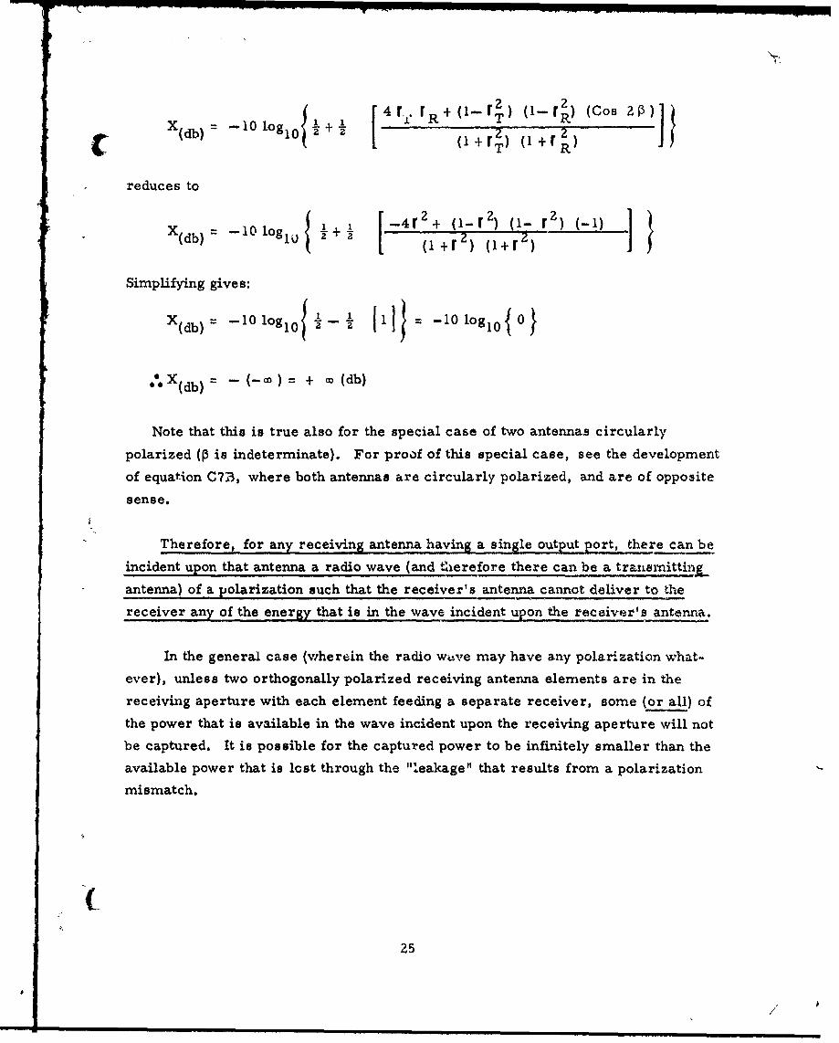
perfectly matched. This is true also for the special case of two antennas circularly
polarized (P is indeterminate). For proof of this special case, see the development
of equation C7A, where both antennas are circularly polarized, and are of the same
sense. Note that it is only in special cases that identical polarizations are matched
polarizations.
Proof of Infinite Polarization Mismatch Loss Theorem
When the two antennas have ellipticity ratios (r) that are equal in magnitude
but opposite in sign (of opposite sense) and the polarization mismatch angle (P) is 900,
equation 2, which is:
)24
4rr 2, (,-r, (CosX(db) l1 10910 +irT) (1 +rR)
reduces to
£ 2 2x 10logl) +4r + (1-r )o(- r ) (-I)
X(db) = -l og~~ ~ +r) I (
Simplifying gives:
. d (-co) + cx (db)
Note that this is true also for the special case of two antennas circularly
polarized (P is indeterminate). For proof of this special case, see the development
of equation C713, where both antennas are circularly polarized, and are of opposite
sense,
Therefore, for any receiving antenna having a single output port, there can be
incident upon that antenna a radio wave (and therefore there can be a transmitting
antenna) of a polarization such that the receiver's antenna cannot deliver to the
receiver any of the energy that is in the wave incident upon the receiver's antenna.
In the general case (wherein the radio wive may have any polarization what-
ever), unless two orthogonally polarized receiving antenna elements are in the
receiving aperture with each element feeding a separate receiver, some (or all) of
the power that is available in the wave incident upon the receiving aperture will not
be captured. It is possible for the captured power to be infinitely smaller than the
available power that is lost through the "leakage" that results from a polarization
mismatch.
25

,/
(This page is intentionally blank)
26

APPENDIX DyANTENNA PATTERNS AND THEIR USE IN DETERMINING VALUES
"NEEDED TO SOLVE THE POWER TRANSFER EQUATION
Antenna Radiation Pattern Coordinate Systems
The complete description of a Fraunhofer Region (far-field) radiation field
of an antenna in free-space requires the use of a multidimensional coordinate
s stem, first, to describe the power gain of the antenna in each direction, and
second, to describe the polarization of the wave radiated in each direction.
IRE Coordinate System
THE INSTITUTE Oi RADIO ENGINEERS (IRE) (now THE INSTITUTE OF ELECTRICAL AND ELECTRONICS
ENGINEERS (IEEE) established a spherical coordinate system for defining directions
from an antenna (reference 26). This spherical coordinate system defines an
azimuthal angle 0 (00 to 3600 "eastwarV") and a polar angle 6 (00 at the "north"
pole). This coordinate system is illustrated by Fig. 34-14, on page 34-13, of
Antenna Engineering Handbook by HENRY JASIK (reference 32) and on page 444 ofS,* 27
Antennas by JOHN DL KRAUS (reference 38)2. Fixed antennas on the surface of
the earth usually have e = 00 at the zenith and 0 = 0 at true north.
IRIG Coordinate System
For moving antennas, IRIG (INTER-RANGE INSTRUMENTATION GROUP) *28 adopted the IRE
coordinate system, with 8 extended to 1800 ("north" to "south"), and established
an arbitrary relationship between the spherical coordinate system and body coord-
inates of a vehicle carrying the antenna (reference 29). The body coordinate system
*27 See JOHN DL KRAUS in Erratum for References (in the References and
Bibliography section).
For information about IRIG, see BEUNRING W. PIKE (reference 45), and/or write
to Secretariat, Range Commanders Council, White Sands Missile Range,New Mexico.
(2
27

adopted is the one used by most aerodynamicists. It consists of three orthogonal
axes (roll, pitch and yaw) in a right-handed system. The antenna coordinate system
and the body coordinate system are related so that the polar axis coincides with the )roll axis, with the positive half of the roll axis at 8 = 0 , so that the positive half
0 0of the pitch axis coincides with 8 = 90° and • = 90°, and so that the positive half
of the yaw axis coincides with 0 = 90 and 0 = 1800. This IRIG system can be
deduced from figure Dl. The nomenclature of this paper agrees generally with that
of the IRIG standard (reference 29). However, complete agreement was impossible
because of the much larger number of symbols required by this paper.
Representation of Measured Data in IRIG Coordinates
Measurements of power gain and polarization of an antenna on a vehicle can
be made at a constant distance from the antenna (but in varying directions from the
antenna) and plotted on the surface of a sphere (with the antenna-carrying vehicle
represented as being at the center of the sphere). For convenience, the spherical
surface can be represented on a flat rectangular surface by making a map projection
of the spherical surface. The IRIG Standard (reference 29) specifies two projection
schemes: an "equal-angle cylindrical projection" and an "equal-area cylindrical
projection." Each projection is upon a cylinder with its axis coinciding with the roll
axis (the polar axis). Both projection schemes provide a constant value of 0 for
a unit of length, on the cylindrical surface, in the 0 direction. The equal-angle
scheme provides the same constant value for 9; but the equal-area scheme provides
a e scale such that equal areas anywhere on the sphere are projected as equal
areas on the rectangular surface. The equal-angle method is the most commonly
used method. The equal-area method has a few special uses, but it is not well
suited to matrix charts (described later).
The measured variables can be represented on the rectangular surface by
printing a matrix of two-digit whole numbers thereon (reference 10) or by drawing
contour lines thereon. The contour type of chart is illustrated by the IRIG Standard
)
28

(reference 29) 29 Figure DZ illustrates the contour method in the left-hand half
of the rectangular surface; the other half illustrates two forms of the matrix
method 30
A convenient method is to measure the following three variables as functions
of the angles e and 0, and plot them on three line-contour charts (or matrix
charts) according to the IRIG Standard (reference 29) method:
1. Right-handed circularly polarized partial power gain ( g •)*31
2. Left-handed circularly polarized partial power gain ( g LH ) *31
3. Tilt angle (T) of the polarization ellipse.*3 2
This method, herein called "ELERT" (for the twirlors e` and el" and
for the Tilt Angle T) is convenient because in the common case where one antenna
of a lirk is a circularly polarized tracking antenna, only a single partial power
gain chart for the other antenna is needed (a tilt angle chart is unnecessary). This
This IRIG Standard was based almost entirely on the pioneering work of theAtlantic Missile Range (now Air Force Eastern Test Range), Patrick AirForce Base, Florida.
*30 The form used for this antenna radiation pattern chart is the author's suggestion
for improvements in the presently used National Range Documentation (NRD) form
(AFWTR form 104, Sep 64). The principal improvements are the provisions forexpanded-scale charts and for plotting either biased matrix charts or biasedcontour charts. Another major improvement is the elimination of grid lines(which, on the presently used form, often obscure important numbers or signs).In connection with the need for expanded scale charts, many of the presentlyused antenna charts become unreadable when reproduced because the necessaryfine detail is lost in the reproduction process.
*31 According to the IRE (IEEE) (and the IRIG) definition of "sense". For this
definition see Appendix E and footnote (*38),
`32 According to the IRIG Standard (reference 29), the tilt angle ( T ) is between a
tangent line in the e direction and the major axis of the polarization ellipse.The angle T is measured counter-clockwise when observing the antenna fromoutside the sphere, and 0o0 T <1800. See T on Figure D1 and in Appendix E.
29
/

/
method is desirable in other cases because the direct measurement of the tilt
angle is, in most instances, easier than the direct measurement of the otherwise
required Relative Phase Angle (6 ) between the two orthogonal circularly polarized }* •33
components of the wave.
Antenna Radiation Pattern Model
Because of the great complexity of vehicle antenna radiation patterns and of
the geometry involved in calculating predictions of the strength of a radio signal,
a three-d mensional model illustrating the IRIG coordinate system and the electrical
vectors and twirlors involved is an essential aid to understanding. For this reason,
the author designed and made a prototype model. The model incorporates a trans-
parent sphere (about 4 inches in diameter) containing a model vehicle (aircraft)
surrounded by a transparent cylinder carrying the projected spherical surface and
contour chart lines (and matrix chart numerals). Associated with this model are
eleven smaller models for illustrating types of antennas, the electric vectors of
their radiated fields, and the various cases of polarization mismatch. To see the
model prototype (or "Stereo-Realist" type color-slide pictures thereof) direct an
inquiry to the attention of the author.
Application of Antenna Radiation Pattern Data
The power transfer equation (equation 1) demands knowledge of the power gain
and the Polarization of an antenna in the direction of the other antenna of a radio
link. Since direct measurement of the power gain would require the measuring
antenna to be of a polarization exactly matched to the polarization of the wave
radiated by the antenna being measured, it is more convenient to observe two ortho-
gonal components of the wave. The measured values of the two orthogonal gain
components ( g) can be used to calculate the power gain (G). By measuring also
the phase relationship of the two orthogonal components of the wave, they can be used
in calculating the polarization mismatch loss (X) demanded by equation 1.
*33 The Relative Phase Angle ( 6") is the angle (00-5 6' < 3600) between the twocounter-rotating field voltage components x& H and *j of the field voltage
i at the instant eSf is in the direction r = 01- (the, direction). 6' ismeasured in the sAhge direction as T , therefore b= 2T . See T in Figure DlNote that e' and e' are "Twirlors" (defined in Appendix E and illustratedin Figure Dl).
30

The two orthogonal components can be either circularly polarized components
(of opposite "sense") or linearly polarized components, one in the e direction and
one in the 0 direction. The phase relationship between the two linearly polarized
orthogonal components can be determined by measuring the electrical phase difference
between the components, where the sign of the phase difference indicates the "sense"*: 3 4
of the wave. The phase relationship between two orthogonal components can be
determined also by observing both the "sense" of the wave and the tilt angle (T) Ofthe polarization ellipse of the wave. This is the method used in this paper. In some
cases, it is feasible, and easier, to obtain T indirectly, by measuring, in addition
to 9 and g e, a linearly polarized partial power gain component in the 0
direction ( g and a linearly polarized partial power gain component in the direction
S= 450 (g 4 5o). From these measurements, T can be computed. However, to
provide redundant data for increasing the accuracy, g . and g 1350 can be measured
also. For detailed information on this method, see L. CLAYTON AND J. S. HOLLIS
(reference 10)' 3. The forthcoming revised edition of the IRIG Standard (reference
29) will include full information on this method.
There are in common use two opposite definitions of "sense". See "Sense"and " r " in the Glossary of Symbols and Terms, Appendix E.
Dr. Clayton kindly supplied the writer with an advance copy of reference (10),in which CLAYTON AND HOLLIS give, as equation (10), an equation that, when ex-pressed in the nomenclature of this paper, is:
-81350)2 T Arc tan e
(e 2-- e)
They also give a table fcr determining the quadrant of 2 T according to thesigns of the numerator and the denominator of the Tangent of 2 T
CLAYTON and HOLLIS point out, on page Z2, that:
e45 + 0 135°) + e2,) = (eU + e0)4513 ( f + eLH RE
Therefore, one can derive:
452 (8e 2j+ e*2;)Zr = Arc tan (cotined
20 e e + (continued)
"31
4PF

S/
From two sets of ELERT charts, data can be obtained for calculating the
antenna power gain and polarization values needed in equation 1 to calculate the
power transfer between two antennas in free-space. In the general case, not only
are complete power gain and polarization data needed on each of the two antennas,
but also complete data on the relative motions, linear and angular, of the two
antennas. With complete antenna radiation pattern data and data on the roll, pitch,
yaw, and translation of each antenna (as functions of time) the distance (D) and the
polarization mismatch angle (P) can be calculated. When the antenna pattern data
are in the IRIG form, the aspect angles (0 and 0) for each of the two antennas can
be calculated from the motion data as functions of time. With two sets of 8 and -
Footnote *35 (continued)
The quadrant ambiguity is resolved by the following data from Table I, onpage 8, of CLAYTON AND HOLLIS (reference 10):
( Sign of the Numerator 1 T
Sign of the Denominator I_-r
+ 0°00< 2T<900
±i +-900< 2T< 180°
1800< 2T< 2700
2'e- 2700< 2 T<3600
1+01 2T =0 0
+ ~2T = 90 0
2T = 180
2i ZT = 2700
1•+1 r is indeterminate(circularly polarized wave)
Note: If one wishes to determine T only, the squared e's can be relativepowers; therefore they can be with respect to any common power reference.
)32

data, the required antenna radiation data can be read from the two sets of antenna
charts. A convenient way to do this, for each of the two antennas, is to draw on a
C transparent overlay sheet, as functions of time, the E and 4 values that define the
line of sight between the two antennas. The 6 and 4 values can be plotted as time-
labeled points, or as time-labeled uncertainty boxes. The advantage of the overlay
sheet method is a single overlay sheet can be used for reading all three charts of
a single antenna set, and when a single vehicle antenna is to couple with many other
antennas, a single set of vehicle anterana charts can be used with any number of
different trajectory aspect overlay charts. Note that a single trajectory aspect
overlay chart can be used with antenna charts for all antennas on the same vehicle.
The Figure DZ chart has a trajectory aspect line to simulate such a line drawn on a
transparent overlay sheet.
The Figure D2 equal-angle chart is one-half contour type and the other half
consists of two kinds of the matrix type. For simplicity, this chart has coarser
than normal intervals. For charts of the matrix type, alternate (odd) values can
be omitted, as shown, thereby displaying (at least roughly) the corresponding
contour lines (reference 10). The Figure D2 chart illustrates the use of biased
values to eliminate polarity signs from the partial power gain contour labels (or
mratrix char.t values). To obtain the true value, subtract the indicated bias from
Scontour or matrix value. *36
For overlay- reading, the rectangular area of every chart, including the
trajectory aspect overlay chart, must be of the same dimensions to within close
tolerances (the Figure D2 chart is not necessarily of the dimensions and the tolerances
indicated thereon). When a standard chart is too small to provide the fine detail
*36 WARNING: Some matrix charts have an inverted db scale (and may or may not
use a db scale that is also biased. To providLc the Figure D2 matrix chart TiltAngle IT) range, in "bigrees" (2 degree units), of 00B thru 8 9 B requires aprinter having 45 keys to provide 90 two-digit characters. The needed 90characters could be provided with a 44 key machine by deleting 00 and represent-ing it by: a) typing 11 on top of 01 to give 41, and b) deleting 89 and representingit by 11 on tnp of 10 to give 10. The term "bigree" has been coined from "bi",meaning two, and "gree", from Middle English (from Middle French "gre"),meaning step or degree. For a mnemonic, think of "Big Degree.
33

req.uired, several expanded-scale standard charts (rather than a larger chart) should
be used. Each expanded scale chart should cover either two side-by-side octants
of the sphere, or the upper, or lower, half of one octant of the sphere. In these )cases the angle scales should have the expanded values.
Note that the coordinate system poles, 0 = 00 and 9 = 1800, are useless (except
for circularly polarized components) because direction is ambiguous. Therefore,
except for circularly polarized components, contour charts, matrix charts and
digital tapes cannot correctly include data for 0 values of exactly 00 and 1800. One
may make measurements at 0 values as close to 00 and 1800 as desired; ordinarily
the closest measurements would be one angle increment (usually 2 , or 1B) away,
and the 8 values 00 and 1800 would be left blank.
Tilt angle charts have the following noteworthy characteristics:
1. The wave radiated by a theoretical dipole that is in the p lar axis (roll
axis) is everywhere of zero degrees tilt angle, and the tilt-angle (-) contour chart
is therefore blank.
2. The tilt angle is indeterminate off each end of any dipole (where no energy
is radiated).
3. The tilt angle is indeterminate at the poles 19•= 00 and 9 = 1800) for any
antenna. If there is a need to resolve this ambiguity, it should be done by measuring
the tilt angle (0° - T < 1800) from the pitch plane containing S6 = 00 (and the roll
axis).
4. The tilt angle becomes indeterminate when the wave becomes circularly
polarized. If the a matrix value or tilt angle contour to represent this condition is 4desired, it should be labeled CP (or left blank in the case of a matrix value) to
indicate the angle is not determinate.
Because of the vast amount of data required to fully describe a complex
radiation field, it is desirable to use automatic means for measuring and plotting
antenna patterns. At least two makers of antenna measuring equipment offer instru-
334

ments for automatic plotting of contour and/or matrix charts having formats similar* 37
to the format of the IRIG Standard (reference 29)C,,Similarly, the magnitude of the calculations involved in solving the power
transfer equation (equation 1), particularly when many ground antennas link with a
single vehicle antenna, makes it highly desirable to use a high speed electronicdigital computer. For this, data must be stored (preferably on magnetic tape) on
the ground antenna's location, on the trajectory of the vehicle, and on the radiation
patterns of each antenna. Matrix data is well suited to digital tape recording. The
Electronic Trajectory Measurement3 Working Group (ETMWG) of IRIG is developing
standard tape formats for such antenna radiation pattern data. These formats will
be included in a forthcoming revised edition of reference 29.
The Air Force Eastern Test Range, Patrick Air Force Base, Florida, has
developed an IBM 7094 computer program to calculate the vehicle orientation angles,
the antenna aspect angles (0 and D), and the distance (D), for up to 40 ground-station
antennas.
An IBM 7094 computer program to read antenna pattern data and trajectory
C data (complete vehicle motion data) and then solve the power transfer equation, is
being developed at The Air Force Eastern Test Range.
Several of the antenna radiation pattern techniques and standards described
herein are directly applicable to the description of other complex multidimensional
coherent or quasi-coherent radiation fields (such as the energy scattered by a complex
object in a radar or laser beam) and to the description of multidimensional thermal
sources of radio frequency noise (such as rocket flames). Similarly, the techniques
are useful in describing multidimensional sources of distortion and/or attenuation
of radio waves (such as the ion sheath surrounding a space vehicle entering the
earth's atmosphere).
"3 7 Exercise extreme caution in interpreting antenna radiation pattern charts
because there a.'e many different charting methods in use, and some chartsare ambiguous.
35
/ si

Calculations From Antenna Radiation Patterns
For the neral case, an antenna radiation field description, according to
the IRIG Sta.,iard method (reference 29), requires at least three charts. Two are
required for orthogonal partial components of power gain, and at least one is
required to complete a description of the polarization of the wave that would be
radiated by the antenna in free-space. Values read from these charts cannot (eý.cept
in special cases) be used directly in the power transfer equation (equation 1) but
can be used to calculate the needed values, as follows.
Power Gain (G)_
With the three charts providing g L' g R-if, and T , the needed power
gain (G) can be calculated from:
GdbI 0 log1 0 alog1 0 (g g 1/0) + alog10( g 1/0) (Dl)
Where the power gain is with respect to an isotropic antenna with no loss and "alog"
stands for antilogarithm.
The above equation derives from the fact that the power gain factor (N) equals
the sum of the two orthogonal partial power gain factors (Q7 and * ) Note
that the factor N is not expressed in decibels (but 9 and G are).
Ellipticity Ratio (r)
In a similar way, the ellipticity ratio ( r) *38 values needed for calculating the
polarization mismatch loss (X) can be calculated from the partial power gain charts
by means of the following equation:
alog° 0( g t'-I/20) + alog 1 0( g f`'120)J (D2)alog g1 -",~/ 20) - alog 1 0 ( g e/,20OD2
Where r is negative when the wave is LH in sense and positive when RH in sense.
",:38 By definition (See Appendix E), the ellipticity ratio (which includes the "sense")
of the wave, is r = ((eRH + e IJ4)/I( e8H - e L'H) , (the signed voltageratio of the major axis of the polarization ellipse to its minor axis) where eR-Hand eLH are "Twirlors" and (i!--I rI<co). Some writers, including LEONaRDHATKIN (reference 22), call this (without the sign) "axial ratio"; others call
(continued) f
36
fp

Polarization Mismatch Angle (p)
Also needed for calculation of the polarization mismatch loss (X) is the
Spolarization mismatch angle (P) 39. This can be obtained from the tilt-angle (T)
charts for the two antennas, in conjunction with data on the angular motion of the two
antennas. Complete data on the motion of the two antennas will yield the needed
distance (D).
Thus, from two sets of antenna radiation pattern charts and from data on the
motion of the two antennas, the required information is obtained (when transmitter
power and frequency are known) to calculate the power transferred between the two
antennas in free- space. When the radio link is not in free- space, additional data
must be obtained for insertion in 2MA and MG of equation 1 to account for the many
additional attenuations (rarely gains) that occur in the propagation of a radio wave* *40
through a bounded sensible medium. Similarly, X must be adjusted for any,*41
distortion of the polarization of the wave.
There are often situations where one, or both of the antennas of a radio link
have some characteristics such that not all of the antenna pattern data indicated
above are necessary. For example, when an antenna has a well-defined beam that
is pointed at the other antenna of the link (a tracking antenna, or one of two fixed
Footnote "38 (continued)
the inverse "axial ratio"; still others call the inverse "ellipticity." The IREDictionary of Terms (reference 25) does not include ellipticity ratio but givesaxial ratio as "the ratio of the major axis to the minor axis of the polarizationellipse." The ellipticity ratio can be determined by measuring the right-handedand left-handed circularly polarized partial components of power gain (G) indecibels with respect to an isotropic radiator with no loss; i.e. , g9P,(dbI)and gLI(dbI). When r is positive, the wave is right-handed in sense. Whenr is negative, the wave is left-handed in sense. This IRE definition of sense
of an electromagnetic wave is opposite to that used in classical physics (seereferences 25, 26, 27, 28 and 29). By the IRE definition, a "right-handed(clockwise) polarized wave" is "an elliptically polarized transverse electro-magnetic wave in which the rotation of the electric field vector is clockwisefor an observer looking in the direction of propagation" (references 25 and 28).
"*39 The polarization mismatch angle, P, (00 < P _5 90 ), is the angle between themajor axes of the two polarization ellipses. P can be calculated from therelative angular positions of the two antenmas and the measured tilt angle (T)
of the polarization ellipse for each antenna.
For example, see WALTER HOLZER (reference 24).`:"41 See H. H. KOELLE (reference 37).
37
p ~ NL mm i m m uuuunnnmn~ nn nnn uwwmm n

/
antennas of a point-to-point radio link), the power gain (G) of the beam antenna,as seen by the other antenna, is constant. When this beam antenna is circularlypolarized, only the circularly polarized partial power gain (g) chart (of that sense) "}is needed for each of the two antennas, because the other orthogonal component doesnot exist in the circularly polarized beam and the tilt angle ( T ) is not needed whenone of the two antennas is circularly polarized. Similarly, if a tracking antennais linearly polarized, only one partial power gain, g 1 or g / (since g 9 =
g "_'I and its tilt angle, T (which ordinarily is constant), are needed.*:4 2
Figure D3 indicates the various possible combinations of antenna types andthe radiation pattern data needed for each combination in order to apply the powertransfer equation (equation 1). *43, *44
Such a radio link is indicated by Figure D3, under Type Ha. An example ofsuch a link is given in reference 30.
*4 3 For experimental data against which the Polarization Mismatch Loss equation,(equation 2) can be tested, see W. SICHAK ANO S. MILAZZO (reference 55).
:"44 For a discussion of antennas and noise sources, see P. D. POTTER, Chapter 9of reference 2.
38

±_NOTE:+AIRCRAFT SHOWN TO ILLUSTRATE
( VEHICLE BODY COORDINATE VEILSYST EM.PIC
SPHERICAL COORDINATE SYSTEMFOR kNTENNA PATTERN0MEASUREMENTS Q
PATTERN DISPLAY SURFACE(EQUAL-ANGLEZAIOCYLINDRICALPROJECTION TNETPAEOF SPHERE
NOTE:~ I', ISTHE-1..--
"7_BODY PIERCING POINT" PY,OF THE NEGATIVE HALF OFTHE YAW AXIS; (P**y) isITS PROJECTION ERT
LINEARLY 0 ec ~ii0POLARIZED 14COMPONENTS 1B(InTangent PlaneJ
~ee0 =180' (TAIL)
0 0 9 0, (S< 1800)(QB< < 9 0B)
ELLIPTICITY RATIO (r):
0 where (i51s I ri OD(NOTE: e j-H and eLH
C Figure D1. Coordinate Systems
39

(This page is intentionally blank)
)40

3 i,14m X It e! Cl! MI I ZI Ill a Xl!I li
A V~ V: SOn g:
:i
SI ®
-- -..
/U IN"22aA
,"S51 "0om i iv/ .00 i!oIYINa "WIWv
k*U3 V AN A3VV 06 100 1 AZ"J'0 - NM.l 4 5- -1VO RAN10 -
0 0
Figure D2A. Contour Chart, Matrix Charts, and Trajectory Aspect Line*'45
*•45NOTE: For simplicity, the intervals shown are coarser than usually used.
Ordinarily, the contour lines for 9 would be at 2db intervals. Thematrix numbers shown for 9 are integral multiples of 2 db (00db thru89db) but the number density (per unit area) in the full matrix ordinarilywould be 25 times that shown.
41
- - ~ ./

410)
0 4A 1Ob *5 1. 0) 0 PI~ *~ a ) ,g 0~ ' a
a .O j.n -. a9
e 0 %-. a~
to a 0j 1. ý$ 1 0,
cm 4) .ý 4
~~~I 0." Z )> 00 2~a~0. V, 0. A
4> 0
~ z U~ 01.
0. . 4
04
0~ 0
~v0 -
k4a T4 :U Sa . e 0
U III)a ' ~ ) I 11 111 I
4) bl a. -
a',--0 4 m004otý $
Ig 64 14) ýý e
Z ~ ex I -4 .OD
.0 .~a 's 4) I a . 0be ~ o' ~ .~ ; 0 0 ; - t , 0.
,2* aý o 0 )0 - 0 : O
0___ w_____ s::::; 0": IM0z
Fiur so 0 0, ca0. 0 0 421

- - 0' 000 .
Of 14 \* 0 0
d T 0 . 4
0 0
.0~ ~ -U .
1- T7 .
-3 '.4 0~ 0 0 , 0 -41
0' 4.-' U
k- o- 0
141 mu 0
0 U 0 A:~w z ~ ~
0 >0
,u 6 ~X X. t 0&1 '0 v& it it ~ '
E It
0 ~ ~ 00 "4
4£ 43

/
S
(This page intentionally blank)
44

( ~APPENDDC E
GLOSSARY OF SYMBOLS AND TERMS
(Greek letters are given first, script letters next)
a (alpha): The symbol used by DR. LEONARD HATKIN for Polarization MismatchAngle, which is called P in this paper.A (and ZA): Power attenuation (M2A is the sum of several power attenuations),
expressed in + db.
AFETR. Air Force Eastern Test Range; Headquarters at Patrick AFB, Florida.
AFWTR: Air Force Western Test Range; Headquarters at Vandenberg AFB,California.
Alcedo ( v: A superscript used within a multi-digit number to indicate that digitsto the left are significant figures and that digits to the right a.re insignificant figureswritten either to establish the location of the decimal point (Picus), or to reduce theerrors caused by rounding-off. A term coined herein from Me Mtin "Alcedo", for"Kingfisher". For a mnemonic, think of "Air Launched Sea Diver."
sLog Antilogarithm. An abbreviation coined in this paper.
AMR: Atlantic Missile Range, (Now AFETR, which see).
"p (oeta)' Polarization Mismatch Angle. The angle between the major axis of thepolarization ellipse of a radio wave at a receiving antenna and that of the far-fieldor Fraunhofer Region radio wave that would be radiated by the receiving antennaif it were used in free-space for transmitting in the reciprocal direction ( 0 °- p < 90°)
Bigree (B): A unit of angle equal to twc -'egrees and indicated by the exponent-likesuperscript B. A mnemenic t rm zoined in this paper to cove-, the range
[(0°- T < 1800) = (0B:5 T <90B)T with the highest resolution that is possible withoutexceeding two numerals. This w. s necessitated by the limitations of matrix-printingtypewriters. For a mnemonic, think of Big Degree.
BUWEPS: United States Navy, Bureau of Naval Weapons.
C: A subscript meaning Circularly Polarized.
CCIR: International Radio Consultative Committee. (See Hz) (See URSI).
CP: An abbreviation for Circularly Polarized.p
6 .(delta prime): A relative phase angle 0 - 6' <360 0). The angle between the twocounter-rotating field voltage components a '-" and e jj• ("twirlors") of the fieldvoltage F at the instant that eL`H% is i•i the direction T = 00 (the 9 direction). 6"ismeasured in Lhe direction of T , therefure 6'= 2 T. See Figure D1 and "Twirlor".
'C45

S/
D: The distance between two antennas of a radio link, in L units.
d: The largest projected linear dimension of an antenna (or of its beam-formingTeflector, lens, or horn). i. e., the largest linear dimension of the aperture.
db decibel): A unit of the ratio of two power levels; db = 10 logl 0 a, where aand b are power levels. See dbI and dbW.
dbI: A unit of power gain of an antenna, with respect to that of an isotropic antennaINing no loss. The intensity of the far-field wave from an antenna in free- spacerelative to what it would be if the antenna were replaced by a lossless isotropicantenna. See db.
dbW: A unit of power level with respect to the power level W (one watt unlessot-hrwise specified). See db.
DDC: Defense Documentation Center, Cameron Station, Alexandria, Virginia,"Th21.
(epsilon): Electric field voltage of an electromagnetic wave observed at a fixedpoint in a plane normal to the direction of propagation of the wave. The resultantof two "twirlors", one of which may be of zero magnitude.
E: A subscript meaning Elliptically Polarized.
e: A partial component of the electric field voltage c
eL'H: The left-handed circularly polarized component of the electric field voltage=, as observed at a fixed point in a plane normal to the direction of propagation.
A left-handed "twirlor". See Sense.
eRj: The right-handed circularly polarized component of the electric field voltage-T7 as observed at a fixed point in a plane normal to the direction of proppoation.A right-handed "twirlor". See Sense.
ve The linearly polarized component in the 8 direction, of the electric field
Vo The linearly polarized component in the 0 direction, of the electric fieldvotge
eO: The linearly polarized component in the direction Tr 450, of the electricf voltage E .
Qjjo: The linearly polarized component in the direction r = 1350, of the electricine oltage E .
ELERT: A method oi describing the polarization of an electromagnetic wave bydefining the le -handed and right-handed circularly polarized partial componentse "ý and *RH (twirlors) of the wave, and the Tilt Angle T of the polarization
ellipse of the wave.
)46

Ellipticity Ratio: See r
ETMWG of IRIG: The Electronic Trajectory Measurements Working Group of theInter-Range Instrumentation Group. Note: For information, see BEUHRING W. PIKE
(reference 45) and/or write to Secretariat, Range Commanders Council, WhiteSands Missile Range, New Mexico.
F: Frequency, in Megacycles per Second or MegaHertz (one Hertz, Hz, is onej-ycle per second. See Hz.).
f: Frequency, in cycles per unit time.
Far-field: See Fraunhofer Region.
Foot, InternationaL Exactly one third of one Yard, International (which see).
Fraunhofer Region: That region of an electromagnetic field in which the energyflow from the antenna proceeds essentially as though it were coming from a pointsource located in the vicinity of the antenna. If the antenna has a well definedaperture (d) in a given aspect, the Fraunhofer Region in that aspect is cormnonlytaken to exist at distances greater than (2d 2 /k ) from the aperture ( X being thewavelength).
Fresnel Region: The region between the antenna and the Fraunhofer Region.
Y (gamma): Power Gain Factor-- see Y and 'Y2"
Y 1: Power Gain Factor of a transmitting antenna in the direction of the receiving"SH-tenna, with respect to that of an isotropic antenna. Y is not expressed in dbL.
Y2.- Power Gain Factor of a receiving antenna in the direction of the transmitting"Tnhrenna, with respect to that of an isotropic antenna. Y is not expressed in dbl.
G (and ZG): Power Gain (EG is the sum of power gains), expressed in + db.
GR. Power Gain of receiving antenna in the direction of the transmitting antenna,
wi ' respect to that of an isotropic antenna, expressed in dbl.
G T: Power Gain of transmitting antenna in the direction of the receiving antenna,
with respect to that of an isotropic antenna, expressed in dbl.
9:' A partial component of the Antenna Power Gain GR or GT. S,-e g j-- and g 9,0Sand g ,; and g 45 o and g 13 5o.
gfH: The left-handed circulzrly polarized partial component of the Antenna Power
G ax GR or GT. One of the orthogonal pair ( g jIj and gj).
S gfj- The right-handed circularly polarized partial component of the Antenna Power9--R}.
=al n GR or G,. One of the orthogonal pair (g",p and g Ri.
47

/
The linearly polarized partial component, in the @ direction, of the Antenna-Power Gain GR or GT. One of the orthogonal pair (g. and g,).
g •: The linearly polarized partial component, in the t direction, of the Antenna- Power Gain GR or GT. One of the orthogonal pair (g. and g.).
g4 5 o: The linearly polarized partial component, in the direction T = 450, of the- antenna Power Gain GR or GT. One of the orthogonal pair (9 4 5 o and 9 13 5 o).
g 13 5o: The linearly polarized partial component, in the direction " = 1350, of theAntenna Power Gain GRor GT. One of the orthogonal pair (945o and g 1350).
Hz (Hertz): One Hertz is one cycle per second. (CCIR Recommendation No. 324,in Documents of the IXth Plenary Assembly, Los Angeles, 1959, Vol. I, page 335;published by International Telecommunication Union, Geneva, 1960.) (reference 31)(see URSI).
0: Infinity
I: Subscript indicating Isotropic Antenna.
IEEE: The Institute of Electrical and Electronics Engineers. (New York, N.Y.)
Intensity (of an electromagnetic wave): Power radiated per unit solid angle, wherethe apex of the solid angle is at the source of the wave.
IRE: The Institute of Radio Engineers. Now amalgamated with the AmericanInstitute of Electrical Engineers to form the IEEE.
IRIG: The Inter-Range Instrumentation Group, of the Range Commanders Council."Tor -information, see BEUHRING W. PIKE (reference 45) and/or write to Secretariat,Range Commanders Council, White Sands Missile Range, New Mexico.
K: A constant in the Power Transfer Equation whose value is a function of the unit
o'fTlength selected. See equation 1.
X (lambda): Wavelength.
L: A selected unit of length. See equation 1. The L in LH does not mean length.
LH: A subscript meaning left-handed. (See RH and Sense).
M: Meter, a unit of length.
Nautical Mil. International: 1,8526 meters. (reference 42)
Orthogonal: n. this paper, orthogonal means not only "at 90°0| but also, for ellipticaland circular polarizations, "of opposite senses and the same degree of ellipticity."(i.e., r R = - rT and, if determinate, P = 900).
"I.(phi): Azimuthal angle; one of two angles used to specify a point on the surfaceo -a here of observation, the other angle being 9. See Fig. D1.
48

r(pi): 3AI41.59
kP (psi): Power.I'-- '.P Opt.: The power available from a lossless radio receiving antenna of Antenna
Power Gain GR when its polarization is perfectly matched to the radio wave. See
5 Rec.
LIRec. The power available from a lossless radio receiving antenna of Antenna
Power iain GR for an arbitrary mismatch between the polarization of the radiowave and the receiving antenna. See 4i Opt.
Li1 : Power fed into transmitting antenna's port.
2 : Power available from port of receiving antenna when the polarization of theantenna is matched to the radio wave.
PR: Power available at output port of receiving antenna (expressed in± dbW).
PT: Power into input port of transmitting antenna (expressed in± dbW).
PP, and p; (Pp), and (P p): Pp is the point where the positive half of thePitch Axis pierces the outer surface of an antenna-carrying vehicle. Pp is thecorresponding point for the negative half of the Pitch Axis. (Pp) is the projectionof Pp onto the surface of the sphere of observation around and centered at the centerof gravity of the vehicle, and (P• ) is the corresponding projection of Pp SeeFigure Dl.
P and PR; , and (P**): Piercing Points of the Roll Axis. See Pp.
Py, and P r; (Py), and (Py.): Piercing Points of the Yaw Axis. See Pp .
PAR• An acronym for Polarization Alternation Reception; coined in this paper.
PAT: An Acronym for Polarization Alternation of Transmissions; coined in this
paper.
PDR: An acronym for Polarization Diversity Reception; coined in this paper.
P. E.: Registered Professional Engineer.
Pega (a): A superscript indicating the entire number is exact b, definition. Coinedherein from the star Pegasos, of The Great Square of Pegasus: for example 1hInternational Yard = OA91440 Meter. See V.
PFD: An acronym for Polarization Frequency Diversity; coined in this paper.
49
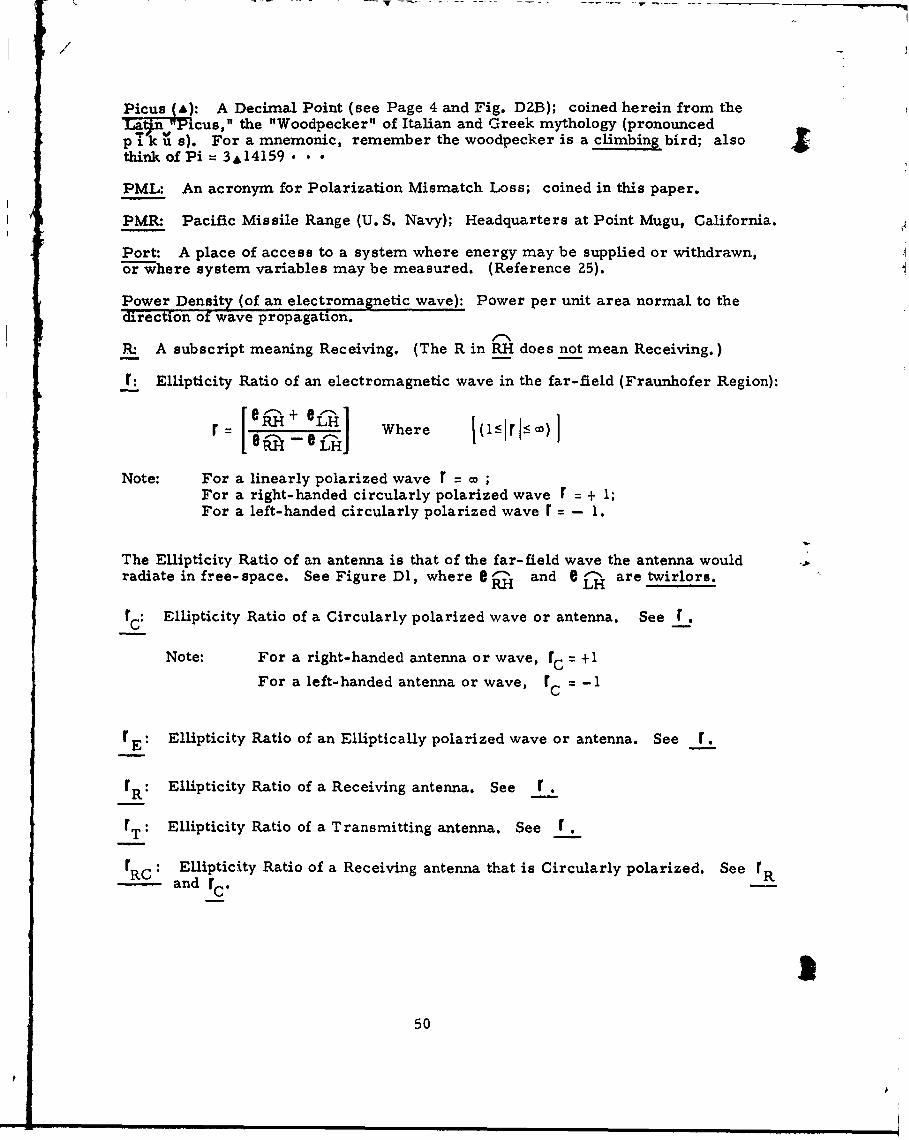
Picus (a): A Decimal Point (see Page 4 and Fig. D2B); coined herein from theLa the "Woodpecker" of Italian and Greek mythology (pronouncedp i k u s). For a mnemonic, remember the woodpecker is a climbing bird; also Sthink of Pi = 3A141 5 9 •
PML: An acronym for Polarization Mismatch Loss; coined in this paper.
PMR: Pacific Missile Range (U. S. Navy); Headquarters at Point Mugu, California.
Port: A place of access to a system where energy may be supplied or withdrawn,or-where system variables may be measured. (Reference 25).
Power Density (of an electromagnetic wave): Power per unit area normal to thedirection of wave propagation.
RI A subscript meaning Receiving. (The R in RH does not mean Receiving.)
r: Ellipticity Ratio of an electromagnetic wave in the far-field (Fraunhofer Region):
r= [: :H ] Where I(1:51r 1:C)Ir--t' - eLH
Note: For a linearly polarized wave r = coFor a right-handed circularly polarized wave r = + 1;For a left-handed circularly polarized wave r i - 1.
The Ellipticity Ratio of an antenna is that of the far-field wave the antenna wouldradiate in free-space. See Figure Dl, where e- and e 8 are twirlors.
r c Ellipticity Ratio of a Circularly polarized wave or antenna. See r.
Note: For a right-handed antenna or wave, rC = +1
For a left-handed antenna or wave, rC = -1
r E: Ellipticity Ratio of an Elliptically polarized wave or antenna. See r.
rR: Ellipticity Ratio of a Receiving antenna. See r.
rT: Ellipticity Ratio of a Transmitting antenna. See r .
rRc : Ellipticity Ratio of a Receiving antenna that is Circularly polarized. See rR- and rc.
50
pi

K
rTC: Ellipticity Ratio of a Transmitting antenna that is Circularly polarized.See r and rC.T d~
rl: DR. LEONARD HATKINS symbol for his "Axial Ratio" of the receiving antenna, where
rl =[rRI such that r 1 does not carry a sign to indicate sense. See r & r 2 .
r 2 : DR. LEONARD HATKIN'S symbol for his "Axial Ratio" of the transmitting antenna,IlV'!re r 2 = I rJTI such that r 2 does not carry a sign to indicate sense. See r & r,
Racon: Radar Beacon, See IRE Dictionary of Electronics Terms and Symbols
(re-erence 25).
RAS: An acronym for Reply Antenna Selection; coined in this paper.
RESA: Scientific Research Society of America.
RH: A subscript meaning Right-Handed. See LH and Sense.
XA: The sum of additional power attenuations such as transmission line losses,expressed in + db.
ZG: The sum of additional power gains such as could be given by a preamplifier at'te output port of a receiving antenna, expressed in + db.
Sense, of an electromagnetic wave (or an antenna): The direction of rotation of the'eectric field voltage vector e (or "twirlor" if circularly polarized). The definitionof sense used in this paper is the one given by the IRE (now IEEE): A right-handed(RH), or clockwise, polarized wave is an ellipt'.ca =y-polarized(i~ncluding circularlypolarized) transverse electromagnetic wave in which the rotation of the electricfield voltage vector E at a point in a fixed plane normal to the direction of propa-gation of the wave is clockwise for an observer looking in the direction of propagation.This definition of sense is opposite to the one used in classical physics. See r.
Sexad: Abbreviation for Sexadecimal, a sixteenth part.
T (Tau): Tilt Angle. The angle between the major axis of the polarization ellipseof an electromagnetic wave (or antenna) and a line in the 8 direction tangent to thesphere of observation. See Figure Dl.
e (Theta): Polar angle; one of two angles used to specify a point on the surface ofa sphere of observation. The other angle is 0. See Figure D1.
T : A cubscript used to indicate Transmitting.
"Twirlor": A physically observable constant-magnitude electric vector that rotatesin a fixed plane about a fixed point (the field voltage components e 634 and eRH aretwirlors). In the Fraunhofer Region, the electric field of any electromagnetic waveobserved at a fixed point in a plane normal to the directibn of propagation appearsas (ur can be resolved into) either:
1. A single twirlor (the wave is circularly polarized).2. Two twirlors of equal magn4tudes but of opposite directions of rotation( (the wave is linearly polarized).
51

/i
3. Two twirlors rotating in opposite directions and of unequal magnitudes
(the wave is elliptically polarized).
Note 1: The Relative Phase Angle 6 between two counter-rotatingtwirlors determines the Tilt Angle T of the polarization ellipse of thewave (including the case of linear polarization, in which the ellipse is a
straight line).
Note 2: Any receiving antenna that captures energy from a radio waveresponds to the observable field voltage vector E (which may or may not
rotate and, if it does, may or may not vary in magnitude during a revolu-tion) by delivering across two terminals of its output port an alternatingpotential difference that varies sinusoidally at the frequency of the radiowave. This potential difference can be expressed in terms of its peak
value, or in terms of its RMS value (which is the method used in thispaper).
Note 3: A term coined in this paper. See R. W. P. KING, H. R. MiMNO ANDA. H. WING (reference 34), page 175.
URSI: Union Radioscientifique Internationale (International Scientific Radio Union).
"Yei-CIR (URSI is a participant) and reference 65.
USAF: The United States Air Force.
USN: The United States Navy.
V : Velocity of a radio wave (or a light wave) in a non-bounded vacuum (free-space).TMe URSI value i s:
V = (299, 79ZA50 OA40 ) km/Sec., = (299,792, 5OO + 4 V0 O ) r/sec.
W : Reference Power Level, ordinarily one watt.
X: Polarization Mismatch Loss (PML) expressed in + db. See Equation 1, where7t-e value of X is to be inserted, and Equations 2 thru 7 for calculating the value ofX.
Yard, International: 19 International Yard = OA91448 Meter. (reference 42).
2KFTAAQSP: A descriptive numbering system for antenna radiation patterns.See Figures D2A and D2B.
v: Alcedo (q.v.)
a: Pega (q. v.)
A: Picus (q.v.)
52

REFERENCES& BIBLIOGRAPHYr *46, *47, *48, *49 *50
(1) YA L. AL'PERT, Radio Wave Propagation and the Ionosphere, Authorizedtranslation from the Russian, Consultants Bureau Enterprises, Inc.,227 W 17th St., New York, N. Y.; 1963. 394 pp.
*(2) A.N. BALAKRI•mSIA, Editor, Space Communications, McGraw-Hill Book Co.,New York, N.Y., 1963. 4 22 pp.
(3) H.M. BARLOW and A.L. CULLEN, Microwave Measurements, Constable & Co., Ltd.,10 Orange St., London W.C. 2: 1950. 399 pp.
* (4) DAVIDK. BARTON, Radar System Analysis, Prentice-Hall, -nc., EnglewoodCliffs, N.J., 1c74. 608pp.
(5) L.V. BLAKE, A Guide to Basic Pulse-Radar Maxitnum-Range Calculation,Part I, U.S. Naval Research Laboratory Report No. 5868; Z8 Dec. 1962.93 pp [Part I - Equations, Definitions, and Aids to Calculation] [ Part IIwill be published later.]
(6) G.M. BROWN, Editor, Space Radio Communication (Symposium Proceedings),Elsevier Publishing Co., Amsterdam; 1962. 631 pp. [42 Authors].
(7) K.G. BUDOEN, Radio Waves in the Ionosphere, Cambridge University Press,Bently House, London NW 1 (32 E. 57th St., New York, N. Y.); 1961.542 pp.
(8) G.W. CARTER. The Electromagnetic Field and Its Engineering Aspects,Longmans, Green & Co., London; 1954. 360 pp.
(9) T. -S. CHu and R.G. KouYoUwAIAN, "On Analysis of Polarization Variation and itsApplication to Circularly Polarized Radiators", IRE Transactions onAntennas and Propagation, Vol. AP - 10, No. 2, Pages 188-192;March 1962.
*(10) L. CLAYTON and J.S. HOLLIs, Antenna Polarization Analysis by Amplitude Measure-ment of Multiple Components, Scientific-Atlanta, Inc., (Atlanta, Ga.) paperpresented at Thirteenth Annual Symposium on USAF Antenna Fc-search andDevelopment, Univ. of Illinois, 15-18 Oct., 1963. 28 pp, (See "ERRATUMfor References."] [Available from Scientific-Atlanta, Inc., P. 0. Box 13654,Atlanta 24, Georgia.] [Also published in the Jan. 1965 "Microwave Journal,"Horizon-House, Inc., 610 Washington St., Dedham Plaza, Dedham, Mass.]
-• 46. All documents are unclassified.
' 47. Author's name is indicated thusly: A.U. THOR.
"48. Anonymous publications are treated as though authored by theissuing organization.
49. Authors cited are indicated by a Star (*).
50. An ERRATUM for CITED REFERENCES follows.
53

/
*(11) J.R. COPELAND. "Radar Target Classification by Polarization Properties."Proceedings of the IRE, Vol. 48, No. 7, pp 1290-1296, July 1960.
(12) W.A. CUMMING. "Radiation Measurements at Radio Frequencies: A Survey ofCurrent Techniques", Proceedings of the IRE, Vol. 47, No. 5, Part I,Pages 705 - 735; May, 1959. [Includes an extensive bibliography.]
(13) D.G. Dowand E.W. HEROLD, Guest Editors, "Introduction to the Plasma Issue",Proceedings of the IRE, Vol. 49, No. 12, Page 1747; December, 1961.
(14) J. DYSON and B.A.C. TUCKER, "An Automatic Contour Plotter for the Investigationof Radiation Patterns of Microwave Antennas", Journal of the LEE,Part IlA, Vol. 93, Pages 1403-1406; 1946.
(15) C.ELFViNG, R. FRANKSand B. LAMBERTY, "Methods of Automatic Analysis and Synthesisof Polarization of Electromagnetic Waves", The Microwave Yournal, Vol 3,No. 11, Horizon House, Inc., Brookline 46, Mass., Page 57; November 1960.
(16) A.Z. FRADIN, Microwave Antennas, (Translation of the Russian), PergamonPress, New York, Oxford, London, Paris; 1961. 668 pp.
(17) HARALD T. FRIIS, "A Note on a Simple Transmission Formula", Proceedings ofthe IRE, Vol. 34, No. 5, Pages 254-256; May 1946.
*(18) GENERAL ELECTRIC Co., Radar Range Calculator, General Electric Co., HeavyMilitary Electronics Department, Syracuse, New York. 1962.
*(19) H. GENT, I.M. HUNTER mad N.P. ROBINSON, "Polarization of Radar Echoes, IncludingAircraft, Precipitation and Terrain", Proceedings of IEE, Vol. 110, No. 12, &Pages 2139-2148, (Savoy Place, London WC2), December 1963.
*(20) R.C. HANSEN. Editor, Microwave Scanning Antennas, Vol I (of II), AcademicPress, New York and London, 1964. 442 pp.
(21) R.C. HANSEN and R.G. STIPHENSON, "Communication at Mega-mile Ranges", TheMicrowave Journal, Horizon House, Inc., Brookline, 46, Mass., Pages 79-85, December 1961 and Pages 79-84; January 1962.
*(22) LEONARD HATKIN, "Elliptically Polarized Waves", Proceedings of the IRE(Correspondence). Vol. 38, No. 12, Page 1455; December 1950. [A lettercommenting on Reference 55.1 [See "ERRATUM for References".]
(23) J. SEARCY HOLLIS, "Antenna Measurements", The Microwave Journal, HorizonHouse, Inc., Brookline 46, Mass. ; Part I, Pages 39 ff, February 1960;Part II, Pages 85-96, March 1960.
*(24) WALTER HOLZER, "Atmospheric Attenuation in Satellite Communications",Microwave Journal, Horizon House, Inc., 610 Washington St., DedhamPlaza, Dedham, Mass., Pages 119-125, Vol. 8, No. 3, March 1965.
*(25) IRE, Dictionary of Terms and Symbols, 1961, IRE, New York, N. Y., 1961.225 pp. [See "ERRATUM for References".]
554

S(26) IRE, Standards on Antennas - Methods of Testin , IRE Standard No. 48,IRE 2.52, IRE, New York, N. Y.; 1948. [Was, in 1963, being revised.]
. *, (27) IRE, "Standards on Antennas and Waveguides: Definitions of lerms, 1953",IRE Standard 53 IRE 2.Sl, Proceedings of the IRE, Vol. 41, No. 12,Page 1721; December 1953.
* (28) IRE, "Standards on Wave Propagation: Definition of Terms, 1950", IREStandard No. 50 IRE 24.SI, Proceedings of the IRE, Vol. 38, No. 11,Page 1264; November, 1950
*(29) IRIG (INTER-RANGE INSTRUMENTATION GROUP), _RIG Standard Coordinate System andData Format for Antenna Patterns, IRIG Document No. 10Z-61,Secretariat, Inter-Range Instrumentation Group (IRIG), Range Commanders'Council, White Sands Missile Range, New Mexico, Second Printing, April1963. 43 pp. [Also available from Defense Documentation Center, CameronStation, Alexandria, Virginia ZIP22314.] [The first printing, September1961, had a few errors that were corrected in the second printing - see"ERRATUM for References".] [The writer was one of the ten authors.][An expanded version of this IRIG Standard is in preparation.]
"* (30) IRIG (INTER-RANGE INSTRUMENTATION GROUP), IRIG System Standards for C-Band(5 cm.) Instrumentation Radars and Beacons, IRIG Document No. 106-59,Secretariat, Range Commanders' Council, White Sands Missile Range,New Mexico; May 1960. 77 pp. [By a Committee of six authors (the presentwriter was Chairman).] [Also available from Defense DocumentationCenter, Cameron Station, Alexandria, Virginia, ZIP22314.]
* (31) ITU, Documents of the IDth Plenary Assembly Los Angeles, 1951, Vol. 1,International Telecommunications Union, Geneva, 1960.
* (32) HENRY JASII, Editor, Antenna Engineering Handbook, McGraw-Hill Book Co.,Inc., New York, N.Y.: 1961. More than 1,000 pp. [39 authors].
* (33) DONALD E. KERR, Editor, Propagation of Short Radio Waves, Vol. 13 of MITRadiation Laboratory Series (28 Volumes), McGraw-Hill Book Co., Inc.,New York, N.Y., 1951. 728 pp.
*(34) RONALDW.P. KING. HARRY R. Muimo and ALEXANDER H. WINc,Transmission Lines, Antennasand Wave Guides, McGraw-Hill Book Co., Inc., New York, N. Y.;1945. 347 pp.
(35) RONALD W.P. KING, The Theory of Linear Antennas, Harvard University Press,Cambridge, Mass.; 1956. 944 pp.
(36) H.C. Ko. "On the Reception of Quasi-Monochromatic, Partially PolarizedRadio Waves", Proceedings of the IRE, Vol. 50, No. 9, Pages 1950-1957,September 1962.
' (37) H.H. KOELLE. Editor, Handbook of Astronautical Engineering, McGraw-HillBook Co., Inc., New York, N. Y., 1961. (2 inches thick).
* (38) JoHN D. KRAUS. Antennas, McGraw-Hill Book Co., Inc., New York, N. Y.;( 1950. 553 pp. [See "ERRATUM for References".]
55

(39) JOHN D. KRAUS Electro-Magnetics, McGraw Hill Book Co., Inc., NewYork, N.Y.; T133. 604 pp.
(40) R.S. LAWRENCE, C.G. LITTLE, and H.J.A. CHIVERS, "A Survey of Ionospheric EffectsUpon Earth-Space Radio Propagation", Proceedings of the IEEE, Vol.52, No. 1, pages 4-27; Jan. 1964, [Includes an extensive Bibliography.]
(41) CAROL G. MONTGOMERY, Editor, Technique of Microwave Measurements,Vol. 11, M. I. T. Radiation Laboratory Series (28 vols.), McGraw-HillBook Co., Inc., New York, N.Y.; 1947. 939 pp. [14 Authors]
* (42) NATIONAL BUREAU of STANDARDS, The Metric System of Measurement, NationalBureau of Standards Misc. Pub. 23Z, Washington, D.C., April, 1961.[Wall Chart.] [See also Units of Weight and Measure, NBS MiscellaneousPublication 233, Dec. 20, 1960. 6Z pp. With Errata Sheet dated December18, 1961.]
(43) PAULJ. NAWROCKI and ROBERT PAPA, Atmospheric Processes, Prentice - Hall,Inc., Englewood Cliffs, N.J.; 1963, 13 Chapters.
* (44) BERNARD M. OLIVER, "Thermal and Quantum Noise", Proceedings of the IEEE,Vol. 53, No. 5, pages 436-454, May 1965.
*(45) BEUNRING W. PIKE, "IRIG, Inter-Range Instrumentation Group - History,Functions and Status, 1959", IRE Transactions on Space Electronics andTelemetry, Vol. SET-6, No. 1, Pages 59-61, March, 1960.
(46) J.A. RATCLIFFE, The Magneto-Ionic Theory and its Application to the Iono-sphere, Cambridge University Press, London, (32E. 57th St., New York22, N.Y.); 1957. 206 pp.
(47) HENRY R. REED and CARL M. RUSSELL, Ultra High Fre uency Propagation, JohnWiley and Sons, Inc., New York, N.Y.; 1953. 56Z pp.
(48) Louis N. RIDENOUR, Editor; Radar System Engineering, Volume 1, M.I.T.Radiation Laboratory Series (28 Volumes), McGraw-Hill Book Co., Inc.,New York, N.Y.; 1947. 748 pp. [32 Authors] .
(49) FRANCIS E. RILEY & J. DOUGLAS SAILOR, Space Systems Engineering, McGraw-HillBook Co., Inc.; 1962. 323 pp.
*(50) A. ROBERTS, Editor; Radar Beacons, Volume 3, M. I. T. Radiation LaboratorySeries (28 Volumes), McGraw-Hill Book Co., Inc., New York, N. Y.;1947. 489 pp. [With Dr. Roberts, the present writer was one of the 24Authors of Vol. 3 and was a member of the I 1-man Editorial Staff.]
* (51) V.H. RUMSEY, G.A. DESCHAMPS, M.L. KALES and J.1. BOHNERT, "Techniques for HandlingElliptically Polarized Waves with Special Reference to Antennas." (Withan Introduction by H. G. BOOKER), Proceedings of the IRE, Vol. 39, No. 5,Pages 533-552; May, 1951. See "ERRATUM for References".
556
r .. . . . . .. . . . . .

(52) S.M. SCALA, A.C. HARRISON and M. ROGERS, Editors; Dynamics of Manned LiftingPlanetary Entry, John Wiley & Sons, Inc., New York, N.Y., 1963. 980pp. (See partIcularly the chapter titled "Communications in the Presenceof Plasma Media" by M.P. BACHYNSKI and G.G. CLOUTIER, pages 206 - 298.)
(53) S.A. SCHELKUNOFF and H.T. FRIiS, Antennas: Theory and Practice, John Wiley &Sons, Inc., New York, N.Y.; 1952. 639-pp.
(54) WILLIAM A. SHURCLIFF, Polarized Light, Production and Use, HarvardUniversity Press, Cambridge, M~ass., 1962. 207 pp.
* (55) W. SICHAK and S. MILAZZO, "Antennas for Circular Polarization", Proceedingsof the IRE, Vol. 36, pages 997-1002, August, 1948.
* (56) SAMUEL SILVER, Editor, Microwave Antenna Theory & Design, Vol. 1Z,M. I. T. Radiation Lab t-a.'ry Series (>28 Volumes), McGraw-Hill BookCo., Inc., New York, N.Y.; 1949. 623 pp. [Ten Authors].
(57) GEORGE SIN$LAIR, "The Transmission and Reception of Elliptically PolarizedWaves", Proceedings of the IRE, Vol. 38, Pages 148-151, February 1950.
"*(58) MERRILL I. SKOLNIK Introduction to Radar Systems, McGraw-Hill Book Co.,Inc., New York, N.Y., 1962, 648 pp.
*(59) KARL R. SPANGENSERG, Editor, Electromagnetics In Space (Subtitle: AntennaConsiderations as Related to Space Communicatiors), McGraw-Hill BookCo., Inc., New York, N.Y., 1965. 277 pp.
(60) FREDERICK E. TERMAN, Electronic and Radio Engineering, McGraw-Hill BookCo., Inc., New York, N. Y., Fourth Edition; 19553 1078 pp.
* (61) FREDERICK E. TERMANand JOSEPHM. PETTIT, Electronic Measurements, 2nd Edition,McGraw-Hill Book Co., Inc., New York, N.Y.; 1952, 707 pp.
*(6Z) L. THOUREL The Antenna, John Wiley & Sons, Inc., New York, N.Y., 1960.405 pp.
(63) T.G. THORNE, Editor, Navigation Systems for Aircraft and Space Vehicles,Pergamon Press, Ltd. (Macmillan Co., New York, N.Y.); 1962, 550 pp.[40 authors]
*(64) U.S. AIR FORCE, Handbook of Radio Frequency Radiation Hazards, T.O. 31-1-80,1958 (Revised 1959), 55 pp.
*(65) ERNST WEBER, "Report on U. R. S. I. Commission I- Radio Measurement Methodsand Standards". Proceedings of the IRE, Vol. 46, No. 7, Pages 1354 -1357, July, 1958. [U. R. S. I. - Union Radioscientifique Internationale.]
(66) H.P. WESTMAN Editor, Reference Data for Radio En ineers, Fourth Edition,Federal Telephone and Radio Corp., 'New York, N. Y.; 1956, 1121 pp.
(67) H. PAUL WILLIAMS, Antenna Theory and De , Sir Isaac Pitman & Sons, Ltd.,London; 1950. Two Volumes: Volunme I, Foundations of Antenna Theory -142 pp., Volume II, The Electrical Design of Antennae - 522 pp.
C (68) YUNG-CHINGYEH, "The Received Power of a Receiving Antenna and the Criteriafor its Design", Proceedings of the IRE, Vol. 37, pages 155-158, February1949.
57
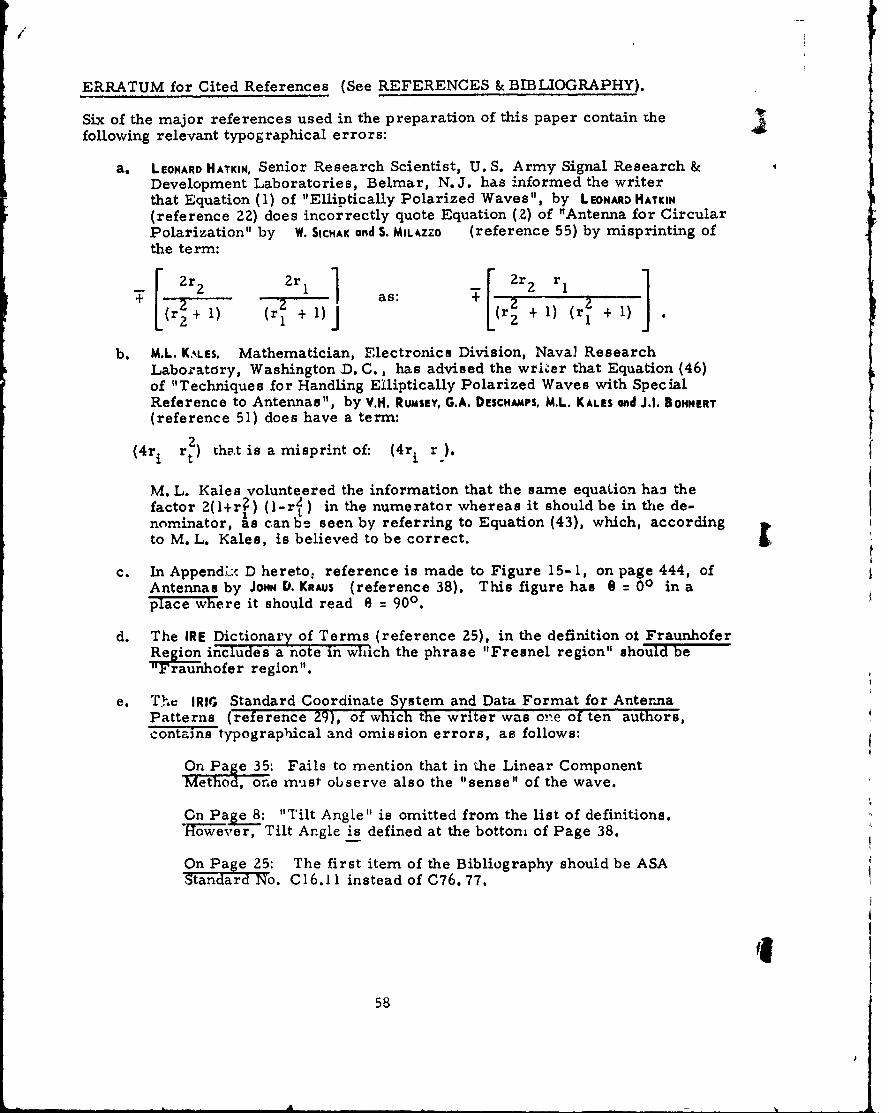
ERRATUM for Cited References (See REFERENCES & BIBLIOGRAPHY).
Six of the major references used in the preparation of this paper contain Thefollowing relevant typographical errors:
a. LEONARD HATKIN, Senior Research Scientist, U. S. Army Signal Research &Development Laboratories, Belmar, N.J. has informed the writerthat Equation (1) of "Elliptically Polarized Waves", by LEONARD HATKIN
(reference 22) does incorrectly quote Equation (2) of "Antenna for CircularPolarization" by W. SICHAK and S. MILAZZO (reference 55) by misprinting ofthe term:
+ r2 + as: 2 22r÷l r ) 2 ÷ )(1 ÷l
b. M.L. KALES, Mathematician, Electronics Division, Naval ResearchLaboratdry, Washington D. C., has advised the wrlier that Equation (46)of "Techniques for Handling El.liptically Polarized Waves with SpecialReference to Antennas", by V.H. RUmSEY, G.A. DEsCHAMPS, M.L. KALES and J.l. BONNERT(reference 51) does have a term:
( 4 ri rt) tha.t is a misprint of: (4r. r
M. L. Kales volunteered the information that the same equation han thefactor 2(1+r?) (1-r2t) in the numerator whereas it should be in the de-nominator, as can be seen by referring to Equation (43), which, accordingto M. L. Kales, is believed to be correct.
c. In AppendL-. D hereto: reference is made to Figure 15- 1, on page 444, ofAntennas by JoHN D. KRAus (reference 38). This figure has 9 = 00 in aplace where it should read e = 900.
d. The IRE Dictionary of Terms (reference 25), in the definition of FraunhoferRegio includes a note in which the phrase "Fresnel region" should be'Trawnhofer region".
e. The IRIG Standard Coordinate System and Data Format for AntennaPatterns (reference 29), of which the writer was on:e of ten authors,contains typographical and omission errors, as follows:
On Paue 35: Fails to mention that in the Linear ComponentMethod, one must observe also the "sense" of the wave.
On eP8: "Tilt Angle" is omitted from the list of definitions.owever, Tilt Angle is defined at the bottom of Page 38. 
On Page 25: The first item of the Bibliography should be ASAStandard No. C 16.11 instead of C76. 77.
5,
58

NOTE: It is the intention of the ETMWG, the ElectronicTraj-•tory Measurements Working Group of IRIG, of
( which this writer was the 1962 & 1963 Chairman, to pre-pare and have issued in the near future an improved andexpanded edition of the IRIG Standard. Meanwhile, asecond printing dated April, 1963, has added (on page 35),a requirement to observe the "sense" (and has elsewhereseveral corrections of minor typographical errors). Theforthcoming revised edition will include magnetic tapeand punched tape formats for antenna radiation patterndata. Readers are requested to advise the IRIG Secre-tariat of any errors found in the Standard, and to suggestimprovements for future editions.
f. Antenna Polarization Analysis By Amplitude Measurement of MultipleC- ponoeuts by L. CLAYTON and J.5. HOLLIS (referenc 10) has a typographicale:ror int last line of page 20. El should be Ej (as can be seen bythe same equation on page 22). [This error was corrected in a laterpublication of this ;Irticle (see Reference 10).]
59
r$
!I

I/
(This page is intentionally blank)
I60

INDEX*
Page
Abstract ...... .. .... ................ ........... v
Air Force Eastern Test Range . . . . . . . . . . . . . . .............. 29, 35,45
Air Force Western Test Range . .. . .. . . . .. .. . . . ............. ii, iv, 4 5
Acknowledgements (In Foreword) ............................ iiii, iv
Alcedo (v) . . . . . . . . . . . . . . .. . . . . . . . . . . . 45,52
AN/FPQ-6 Instrumentation Radar . . . . . . . . . . . . . . . . .. ...... .. 12,13
AN/FPQ-10 Instrumentation Radar . . . . . . . . . . o . . . . . . . . 12
Antenna Patterns. .. .. .. .. . .. .. .. .. . .. .. .. . 27
AN/TPQ- 18 Instrumentation Radar ... . ..... . 12,13
Approval Statements . . . ..... . . . . . . . . . iv
Atlantic Missile Range (AMR) . . . . . . . . . . . . . . . . . . . . . . . . . . . . .. 29
P, (Beta), Polarization Mismatch Angle . . . . . . . . . . . . . . . . . . . . . . 37,43.45
BAILEY, H.H . . .......................................... 1.5
* BARTON, DAVIO K. . . . . . . . . . . . . . .o . . . . . . . . .** . . .. . .a . . . 12
Beacon Equation .. .. .. .. .. .. .. .. .. .. .. .. .. .. .. .. .. .. . .. 15
BENTON, ROBERT F. . . . . . . . . . . . . . . . . . . . . . . . ..*. . . . . . . . . . . . . ... iii
"k BELLAMY, J.. . .. . . . . . . . . . . . . . . . . . . . . . . . . . . . . ... . 12
Bibliography .. .. .. .. .. .. .. .. .. .. .. .. ... .. . .. .. . 53
"Bigree" . ,........ . . .. . . . . .. * e. .. . ..... 33 ,39,41,45
BOWEN, VLLIAM A. . ... ..... . . .. .. . . . . . . . .. . iii
*NOTES:Greek letters are given first.
Personal names are given thusly: A. U. THOR (or THOR, A. U.).
Star () indicates cited author.
61
A

/
Index (cont'd)
Page
BRAUN GERHARD W . . . . . . . . .
Calculations from Patterns .......................... .. 36
Chart, Antenna Pattern . . . . . . . . . 41
Charts, Contour . . . . . . .. . .... * . . . . . .. . 28,33,36,41
Charts, Matrix . ... .. . . ..... ... .... .... .. . . 28,33,36,41
'" CLAYTON, L. . .. . . . .. . .. . . .. .. . . .... .. ..... 31,53,59
Coordinate Systems .. ........... ........... .. . .. 39
" COPELAND, J. R. . . . ... . . . . . . . . . . . . . . . . . . . . . . . . . . . . . . . . . . .9
6 (delta prime), Relative Phase Angle .......... .. ..... .... . 30,45
D, Distance . . . * . . * . . *. . . . . . . . .. * a e a . . . . . . . 4,16,46
d, Diameter of Antenna .... 9.*... .... . . ............. 4,46
Defense Documentation Center ............ ........ Inside Front Cover
DONNELLY, A. V. . . . . . . . . . . . . . . .
"" DUNSAR, A. S . *. . . . . . . . . . . . . . . . . . . . . . 9 . . . . . . . .. ... .. . .. .. 12
E , (epsilon), Vector Field Voltage .............. * . . . 30, 39, 43, 46
6, Partial Component of 99999.... 9... .. 9... 9.. 9... 30,31,39,43,46
ELERT Method . ....... .. .. ... .. .. ... .... s 99 o 9s9 29, 39,46
Ellipticity Ratio (r) . 9.. . ............ 5, 19, 36, 39,43,47, 50, 51
Equation, Beacon . . . . . . . 15
Equation, Racon . . . . . 9 *99 9.............. . ...... . 15
Equation, Ellipticity Ratio ( r) . . . . . . . . . . . . . ...... ... ... 36, 39,50
Equation, Polarization Mismatch Loss ...................... 5, 20
Equation, Power Transfer . . . . . . . . . . . .................... 4, 15
Erratum for Cited References ............................. 58
62
Index (Cont'd) Page
1l
ETNE G of IREIG .................................. 35,47,59
FETHER, EUGENE M. . .* * .9 .9 9 9* 9 .9 9 99 .. .* .99 ....
Figure D1, Coordinate Systems ........................ 39
Figure D2, Contour Chart, Matrix Charts & Trajectory AspectLine . . . . . . .. 41,42
Figure D3, Table of Data Requirements .................. 43
Foreword .. . .. ... . ...... .... **** *....... ii
Y , (gamma), Antenna Power Gain Factor . ................ 15, 36,47
G, Antenna Power Gain, in dbI .. . *. .. . . . . . ... ... 4, 16, 30, 36, 43, 47
g, Partial Power Gain, dbI. o o. .................. 29, 30, 36,43,47
Glossary of Symbols and Terms . . . . . . . . . . .. 45HANSEN, R. C s. . . . . . .. .o . . . . . . . . . . o . . 14
* HATKIm, LEONARD o 9 9 99. . .. ............... .......... 20,54
* HOLLIS, J. S. . . .9 ............ ....... .... .. *... . 31,54
HOLZER, WALTER a....9........ ... .9........ .... .. ... 37,54
SIEEE .. ............. o.. .. . .. .... ...... .. . 27, Z9, 37,48, 54
Introduction * * .. . . .. . .. . .. . .. 9 9 9 ......
* Inter-Range Instrumentation Group (IRiG) ..... 9 27 - 32, 35, 36, 48, 59
* IRE ...................... ........... ......* 99 See IEEE
' KERR, DONALD E.. .* . . . . . . ... . . . . . ... . . . . . . . . . . . . ... .. .. 10
SKING, et al, .. .. .. .. .. .. .. .. .. .. .. .. .. .. .. .. ..... 52
"* KOELLE, H. H. . . . . . . . .. . . . . . . . . . ........................ . . . 37
" KRAUS, JOHN D . ......... . ........................... 58
* LEE, TUCK HOP .*. . . # . # . . .. . . . . . . . . . . .. . . .. . . . 12
LEISH, JERALD . . . . . . . . . . . . . .. . .. ... . . . . .iii
63
S~/

Index (Cont'd) Page
LICHTI, K. I . ....................................... ii
MATSEN, MD M . . . . . . . . . . . . . . . . . . . .
M AKEF, DWI.HT L . . . . . . . . . . . . . . . . . . . ..*0
"14hLAZZo, S ................... ...................... 20, 38
Model, Antenna Radiation Pattern ...................... 30
MORRIS, GORGE W., JR. • ... . . . . . . . . iii
SOLIVER, BERNARD M. . . . .. . . . ...................... 15
Pacific Missile Range (PMR) . iii, 50
PAR, Polarization Alternation Reception .................. 10,49
PAT, Polarization Alternation of Transmissions . . . . . . . . . 8 - 13, 49
PDR, Polarization Diversity Reception . . . . . . . . . . . . . ..... 8- 13, 49
P e g a ( a ) . . . . . . . . . . . o. . . . . . . . . . . .. . . . . . .. . . . . .... . 4 9
PFD, Polarization Frequency Diversity ....... 9,49
Picus (A) 99.9. 9. 9.9.9. 99.9...9 .. 99 .9 .9 .9....9.. 4,50 6•"PIKE, BEUHRING W .. . .. .. .. .. .. .. .. .. .. .. .. .. .. . .. 12, 27, 47,48, 56, 58
(Refs. 4. 10, 29, 30, 45, 50)
Polarization Mismatch Angle, P . . . . . . . .............. 20, 37, 43,45
Polarization Mismatch Loss (PML) . . . . . . .0. . * 0 ... . . . . . . 19, 50
Polarization Mismatch Theorem . . . . ... . . .. . . .. .. . 7, 19, 24, 25
Polarization Problems in Radio and Radar . ... 9.9...*..9... 7
SPOTTER, P. D. . . . . . . . . . . . . . . . . . . . . . . . .. . . . . ... . . . . . . 38
Power Gain, Y o...o...... ........ .. ..... .......... 9 15,36,47
Power Gain, G .*. .o . * .. . . . . . . . . * s * # .. . . . . . s. . . . 4, 30, 36, 43, 47
Power Gain, Partial, g . . . . . . . . . . . . . . .. . . . . . . . .. . . 29, 30, 36, 43, 47
Pow3r Transfer Equation . . * . . . .. .. .. . . . . . . .. . . .. . .. .. 4, 15
r, Ellipticity Ratio ............ ............ 5, 19, 36, 39, 43, 47, 50
Racon Equation .............. 9........9.9.9.9.9... . 15
64

Index (Cont'd) Page
Radar Range Equation ............................... 10
Radiation Patterns ...... 27
RADOM, STANLEY R. iv
RAS, Reply Antenna Selection ..................... 11
References ............................... o * • 53
Relative Phase Angle, 6' .............................. 30, 45
Release Notices ............................ Inside Front Cover
Removable Copies of Pages 4 & 5........................ 67
Rice University* . ................. iii
RITLAND, LLOYD . . .. . . . . . . . . . . . . . . . . . . . . . . . . . . . . . . . . . . iii
,• ROBERTS, ARTHUR . . . . . . . . . . . . . . . . . . . . . . . . . 12
'I RUmSEV, V. H. et al. . . . . . . . . . . . . . . . .. . . . . . . .. . . ... . .. .. 20
"Sense" of Electromagnetic Wave . . . . . . . . . . . . . . . . 29, 31, 36, 39, 51,59
"* SICHAK, W. . . .. . . . . . . . . . . . . . . . . . . . . . . . . . . . . . . . . . . . . . 20,38
Side Lobe Tracking . . . . . . . . . . . . . . . . . . . . . . . . . . . . . . . * . 13
SSILVER, SAMUEL . . . . . . . . . . . . . . . . . . . . . . . 13
SKEWS, LESLIE K. , . .................... . . .. * . * . .. . .iv
•, SKOLNIK, MERRILL I. * # . . . . . . . .. . . * .. . . . . . 12
12SSPANGENBERG, KARL R. . . . .. .. . . . . .. . .. . . . .. . ... . . . ....
Symbols and Term s . . .. * . . . . . . . . * . . ... .. . . . . .. .. a . 45
viiTable of Contents . .. . * . . . . . . . . . . . . . . . . . . . . . . ....
9Target, Radar . . . o * . . . ................... . . . .. * . . . . . . . . . 9
TENDICK, CULLEN B. . . . .. . . . . . . . . . . . . . . . . . . . . . . . . . . .
'"TERMAH, F. E .. . . . . . .. . . .. . . .. . . . . . . . . . . .. .. .. .. . . . .. 17
Theorem, Polarization Mismatch . . . . . . . . . . . # . . * . . . 7, 19, 24, 25
( *• The Rice University (Houston, Texas), formerly called the RiceInstitute (founded by WILLIAM MARSH RICE).
65
/

Index (Cont'd) Page
* THOUREL, L......... .* ...... . • ........... . ............ 17
S~T, (tau), Tilt Angle ,..,, . . . . . . . . .29, 31,34, 39943,$51,59
Twirlor .a. .*.. a ... .*toa*.a a .. a ... , a a . a . ..29,36,39,43,551
" U.S. Air Force . . . . . . a...... a.. a.... .. .a a a a .. ii, iv, 17
U.S. Navy. ..... . . . .. . . . . ......... . . .. a . .a.... ii, iii, 17
Velocity of Light (V) . . . ...... a .. ......... .t a. .a a a e..... 15, 52
X, Polarizatikn Mismatch Loss, Equations . . . .......... a . 5, 19
v (Alcedo) . . . . . . . . . .. aa....aaaa...a..a..a 45,52
* (Pega) .. . .. ... . .. . a . .. 49, 52
* (Picus) .. aaaaaa. aa.a. aaa aa...aa......... & .... a . 50, 52
66

REMOVABLE COPIES OF PAGES 4 AND 5.
For the convenience of the reader, removable copies of the two
pages that have the Power Transfer Equation (Equation 1) and the Polar-
ization Mismatch Loss Equations (Equation 2 through Equation 7) are
included as not-numbered sheets following tho- next page. These removable
(perforated) sheets are printed on translucent paper so they can be easily
reproduced.
They may be reproduced as a set provided all information is included.
For information regarding reproduction and release of this Technical
Report, see the Release Notices on the inside of the front cover.
67
Aml unn n nn m n n m mwl ~ m n n u n nnmulu lm ;u mummllnnm
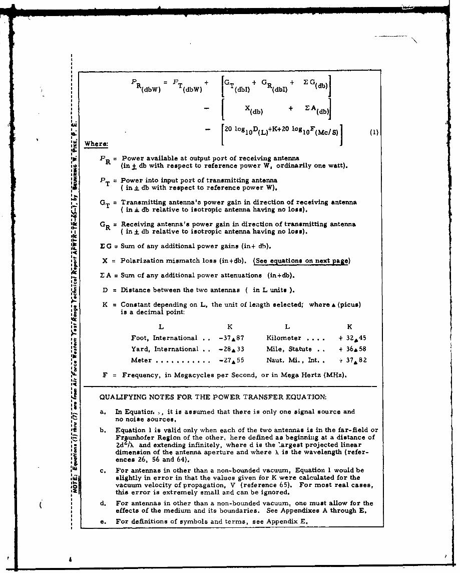
p G Ga +
' I•.. i . , L. J.i i i- "I I II I ' '
PR(dbW)= PT [GW+ T (dbi) + GR(dbi) + G(db)
- + ZAWee
(db)T(1
.2 0 lo go D, (, )+ K + 2 O l o, F ( M c 8 )( ," Where."
P = Power available at output port of receiving antennaR -(in ± db with respect to reference power W, ordinarily one watt).I'
S PT = Power into input port of transmitting antenna( in mI db with respect to reference power W).
a GT = Transmitting antenna'a power gain in direction of receiving antennaS( in . db relative to isotropic antenna having no loss).
G = Receiving antenna's power gain in direction of transmitting antennaI ( in - db relative to isotropic antenna having no loss).
E G = Sum of any additional power gains (in+ dh).It
I X = Polarization mismatch loss (in+db). (See equations on next page)it
9 A = Sum of any additional power attenuations (in+db).
D = Distance between the two antennas ( in L units ).
K = Constant depending on L, the unit of length selected; where A (picus)IF• is a decimal point:
L K L K
I Foot, International . . -37A87 Kilometer . . .*. + 32445
,, Yard, International . . -Z 8 &33 Mile, Statute . . + 36&58
"" Meter ........... -27%55 Naut. Mvii., Int.. + 37%82
F = Frequency, in Megacycles per Second, or in Mega Hertz (MHz).'4
QUALIFYING NOTES FOR THE POWER TRANSFER EQUATION:
a. In Equation ,, it is assumed that there is only one signal source andno noise sources.
"b. Equation 1 is valid only when each of the two antennas is in the far-field orFr~unhofer Region of the other, here defined as beginning at a distance ofZd'IX and extending infinitely, where d is the largest projected lineardimension of the antenna aperture and where X is the wavelength (refer-"ences 26, 56 and 64).
c. For antennas in other than a non-bounded vacuum, Equation 1 would beslightly in error in that the values given for K were calculated for thevacuum velocity of propagation, V (reference 65). For most real cases,this error is extremely small and can be ignored.
d. For antennas in other than a non-bounded vacuum, one must allow for theeffects of the medium and its boundaries. See Appendixes A through E.
e. For definitions of symbols and terms, see Appendix E.
p 4 p

Case:
(Polar-izations) X = Polarization Mismatch Loss (in+db)
Eip. V 4rTr + (-r2 (l-ri) (Con 20)u', 4 -10ologl0 ½+ T R T):0: Ei g (l+ (1+r Zi (2)
:a Ellip. R)
'0 (1-rE) (Coso 23 -1 logl0 2 •
', Q)Ellip. r
:••- 10Ologlo , + • ,, Ezcc Circ. (f + rE) (4)
I I 0 +
LL n Li i.:.q -llg4f+ (Cots 2),t •-10 loglo ½+', a n 1 1 )
I C
Lin.
I, f h oarzto llisu oismnraiwee( • I-•.*
S --- 10log 01 + 3db
I•., Ci. cE men Eipical oaie;Cmas iclryPlrzd
Ci c (6)
it;G
II-I 0 l l lll ll l 3! I II
Circ.4+ -10 11+ r r 1 db When r
-. -1og 1 0 ICr C TC RC
Circ. I=+dbWnrTC =-rRC (7)0 (
I.-
'~Where *4 : r =Ellipticity Ratio, the signed voltage ratio of the major axis ofthe polarization ellipse to its minor axis, where (1_I r 1:5 5*
p= Polarization Mismatch Angle, (00 < 9 0 o 5
T means Transmitting; R means Receiving.
E means Elliptically Polarized; C means Circularly Polarized.
S *4: For definitions see Appendix E, Glossary of Symbols and Terms.
U1 *5: See Appendixes A through E.If..-

UnclassifiedSecurity Classification
DOCUMENT CONTROL DATA- R&D(Spcurity classification of title, body of abestract and indexing annotation muest be entered when fne overall report is clasaified)
I ORIGINATIN G ACTIVITY (Corporate author) 2a REPORT SECURITY C LASSIFIC.TION
Air Force Western Test Range 2b Unclassified
3. REPORT TITLE
Power Transfer Between Two Antennas with Special Reference to Polarization
4. DESCRIPTIVE NOTES (Type of report and inclusive date@)
Technical ReportS AUTHOR(S) (LMat name, firet name. initial)
Pike, Beuhring W.
S REPORT DATE 7a. TOTAL NO. OF PAli I 7b No. Or Rars
December 1965 75 68$a CONTRACT OR GRANT NO. 9a. ORIGINATOR'$ REPORT NUM ER(S)
N/Ab. PROJElCT NO.NA NAFWTR-TR-65-1
N/A _ _ _ _ _ _ _ _ _ _ _ _ _ _
9 Sb, THIR RIPORT NO(S) (Any othesrnumbere that may be aaulsned@is report)
d None10 AVA ILAIILITY/LIMITATION NOTICES
Distribution of this report is unlimited.
I1. SUPPLEMENTARY NOTES 12. SPONSORING MILITARY ACTIVITY
Hq AFWTR (WTNR)None Vandenberg AFB, California 93437
13 ABSTRACT
The literature abounds with examples of a convenient equation ("the beaconequation") for calculating the free-space power tranlsfer between two widelyspaced radio antennas having polarizations that are matched for maximum powertransfer. On the other hand, convenient equations for making such calculationswhere the polarizations are not matched are very scarce. In this paper the wellknown beacon equation has been combined with a published (but relatively litcleknown) general equation for polarization mismatch loss, so as to yiele a com-plete general equation for calculating the power transfer between two widelyspaced antennas in free-space. For convenience, the portion of the generalpower transfer equation that accounts for polarization mismatch loss has beenreduced to yield a special equation for each of the five limiting cases. Alsogiven are discussions of polarization problems and solutions in radio and radarand a discussion of antenna radiation field representation methods and theiruse in calculating the power transfer between two antennas. This 75 pageTechnical Report includes a Glossary of terms and a Bibliography of 68references.
eJ
DD I JAN" 4 1473 UnclassifiedSecurity Classification