defense nuclear agency alexandria, va 22310-3398 · defense nuclear agency alexandria, va...
TRANSCRIPT

AD-A261 657
Defense Nuclear AgencyAlexandria, VA 22310-3398
DNA-TR-92-78
Ultraviolet Waveguide Lasersfor Phased Array Lidar
C. Paul ChristensenPotomac Photonics, Inc.4720-E Boston WayLanham, MD 20706 DTIC
~MAR0 8 19931February 1993 s iW
Technical Report
CONTRACT No. DNA 001 -89-C-0064
Approved for public release;distribution is unlimited.
-o CA )002-O4858

Destroy this report when it is no longer needed. Do notreturn to sender.
PLEASE NOTIFY THE DEFENSE NUCLEAR AGENCY,ATTN: CSTI, 6801 TELEGRAPH ROAD, ALEXANDRIA, VA22310-3398, IF YOUR ADDRESS IS INCORRECT, IF YOUWISH IT DELETED FROM THE DISTRIBUTION LIST, ORIF THE ADDRESSEE IS NO LONGER EMPLOYED BY YOUR
ORGANIZATION.
. 9-4

DISTRIBUTION LIST UPDATE
This mailer is provided to enable DNA to maintain current distribution lists for reports. (We wouldappreciate your providing the requested information.)
NOTE:10 Add the individual listed to your distribution list Please return the mailing label from
Ftthe document so that any additions,o Delete the cited organization/individual. changes, corrections or deletions can
be made easily.o Change of address.
NAME:
ORGANIZATION:
OLD ADDRESS CURRENT ADDRESS
TELEPHONE NUMBER: ( )
DNA PUBLICATION NUMBER/TITLE CHANGES/DELETIONS/ADDITIONS, etc.)(Attach Sheet i0 more Space is Required)
DNA OR OTHER GOVERNMENT CONTRACT NUMBER:
,' CERTIFICATION OF NEED-TO-KNOW BY GOVERNMENT SPONSOR (if other than DNA):
SPONSORING ORGANIZATION:
CONTRACTING OFFICER OR REPRESENTATIVE:
SIGNATURE:

DEFENSE NUCLEAR AGENCYATTN: TITL6801 TELEGRAPH ROADALEXANDRIA, VA 22310-3398
DEFENSE NUCLEAR AGENCYATTN: TITL6801 TELEGRAPH ROADALEXANDRIA, VA 22310-3398

Form ApprovedREPORT DOCUMENTATION PAGE No 070-18
Public em buden for Ois ecaon of Information Is esnad t aveae 1 hour per respOn Including tMe tme $or mrevewnog wmtuclons. searcting ee ng dta sources.gawke ad maintaing fte data rneded. and - mplI 0n end r*vie w collection of WInortion. Send cornments regarding this burden setimate or any other aoect of thioection of I rt on. Including suggestions for reducing digs burdken to Waslhington Hedquaflars Serisces Directoate for Inraton Opersatiks and Repo•rt. 1215 JeffersonDas H�i�way. Suit 1204. Art•ngton. VA 22'0-4302, and to the Oce o Management md Budget, Papewoo Reduction Proe (0704.01-). Wnh•wgn, C 20603
1. AGENCY USE ONLY (Leave blank) 2. REPORT DATE 3. REPORT TYPE AND DATES COVERED
930201 Technical 890710- 9206304. TITLE AND SUBTITLE 5. FUNDING NUMBERS
Ultraviolet Waveguide Lasers for Phased Array Lidar C - DNA 001-89-C-0064PE - 62715H
6. AUTHOR(S) PR - SFTA -SB
C. Paul Christensen WU - DH091050
7. PERFORMING ORGANIZATION NAME(S) AND ADDRESS(ES) 8. PERFORMING ORGANIZATIONREPORT NUMBER
Potomac Photonics, Inc4720-E Boston WayLanham, MD 20706
9. SPONSORING/MONITORING AGENCY NAME(S) AND ADDRESS(ES) 10. SPONSORING/MONITORINGAGENCY REPORT NUMBER
Defense Nuclear Agency6801 Telegraph Road DNA-TR-92-78Alexandria, VA 22310-3398RAEV/Nichols
11. SUPPLEMENTARY NOTES
This work was sponsored by the Defense Nuclear Agency under RDT&E RMC Code B7664D SF SB 00042PRPD 1950A 25904D.
12a. DISTRIBUTION/AVAILABILITY STATEMENT 12b. DISTRIBUTION CODE
Approved for public release; distribution is unlimited.
13. ABSTRACT (Maximum 200 words)
This is the final report for a SBIR Phase II investigation of xenon Chloride waveguide laser arrays. Using elec-trodeless microwave discharge techniques, we have constructed an optimized XeC1 waveguide laser that couldserve as the basic building block for a XeC1 laser array with average power in the watt range. The beam producedby the laser is highly multimode. This has been shown to limit the efficiency of the laser, and will hinder its appli-cation to coherent arrays.
14. SUBJECT TERMS 15. NUMBER OF PAGESLaser Ultraviolet 34Array 16. PRICE CODE
Lidar17. SECURITY CLASSIFICATION 18. SECURITY CLASSIFICATION 19, SECURITY CLASSIFICATION 20. LIMITATION OF ABSTRACT
OF REPORT OF THIS PAGE OF ABSTRACT
UNCLASSIFIED UNCLASSIFIED UNCLASSIFIED SAR
NSN 7540-280-5500 Standard Form 296 (Rev.2-89)SPr-osried by ANSI Sit. M162WI-02

SECURITY CIASSIFICATION OF T1IS PNGP
CLASSIFIED BY:
N/A since Unclassified.
DECLASSIFY ON:
N/A since Unclassified.
SECURrIY CLASSWI1WCATION OF THIS PAGE
UNCLASSIFIED

CONVERSION TABLE
MULTIPLY BY TO GET
TO GET BY DIVIDE
atmosphere 1.1013 25 x E +2 kilo pascal (kPa)
degree (angle) 1.745 329 x E -2 radian (rad)
erg 1.000 000 x E -7 joule (J)
erg/second 1.000 000 x E-7 watt (W)
inch 2.540 000 x E -2 meter (i)
micron 1.000 000 x E-6 meter (i)
pound/in2 (psi) 6.894 757 kilo pascal (kPa)
torr (mm Hg, 00 C) 1.333 22 x E-1 kilo pascal (kPa)
Acoesslon ForINTIS GRA&I G
D•TC 7.,,, 11ur Ir U.:..rC C, 0
l•'L :C
_D is •t! z,'-I tio nf. . ..SAvahill .ot r C•
iii Dist Speoia1

TABLE OF CONTENTS
Section
Conversion Table .................................... iiiList of Illustrations ................................ v
1 INTRODUCTION .......................................... 11.1. Optical Phased Array Transmitters ................ 11.2. Overview of UV Waveguide Laser Technology ........ 21.3. Waveguide Excimer Lasers in Phased Arrays ........ 4
2 PHASE II OBJECTIVES ................................... 63 OVERVIEW OF PHASE II ACTIVITY ........................ 8
3.1. Waveguide excimer technology at the beginningof the project .. ................................ 8
3.2. Construction of the basic array element .......... 83.3. Fabrication of the discharge structure ........... 93,4. Microwave generation and delivery ................ 113.5. Efficiency and specific power of waveguide
XeCl lasers ...................................... 123.6. Optimization of discharge tube geometry .......... 133.7. Optical filling factor and transverse mode ....... 163.8. Performance of the optimized single tube
laser ............................................. 183.9. Influence of waveguiding loss and transverse
mode on efficiency ............................... 183.10.A Two Element Array ............................... 213.11.Application to Commercial Products ............... 21
4 CONCLUSIONS ........................................... 225 LIST OF REFERENCES .................................... 23APPENDIX
LASER BEAM PROFILES .................................. A-I
iv

LIST OF ILLUSTRATIONS
Figure
1 Semi-schematic illustration of waveguide excimerlaser configuration (top) and conventionaldischarge-pumped excimer laser. Note differencesin size of the active region, gas flow systems, andelectrode location .................................... 3
2 Phased array ultraviolet source fabricated formwaveguide excimer lasers. The amplifier sectionscould be a single pass or multipass amplifiers orinjection locked oscillators .......................... 4
3 End view of uv waveguide arrays fabricated fromredrawn tubing with applied metal electrodes .......... 7
4 Cross-section of the discharge tube mount ............. 10
5 Pulse energy as a function of magnetron current fora 0.2 mm x 2 mm x 20 cm discharge tube ................ 15
6 Pulse energy as a function of peak magnetroncurrent for a 0.5 mm x 1 mm x 20 cm dischargetube .................................................. 15
7 Pulse energy as a function of peak magnetroncurrent for a 0.5 mm x 2 mm x 20 cm dischargetube .................................................. 16
8 Optical arrangement used for analysis ofthe laser beam profile .............................. 17
9 Average power as a function of pulse repetitionfrequency for an optimized single element module ...... 18
10 Effect of excess loss (waveguiding loss, mirrorcoupling loss, etc.) on a 0.05 x 0.2 x 35 cmwaveguide excimer laser with gain of 4%/cm andabsorption loss by plasma of .25%/cm. Reflectivityof output coupler is 80% .............................. 19
11 Beam profile at tube end of 0.2 mm x 2 mmrectangular tube ..................................... A-i
12 Beam profile at tube end for 0.5 mm x 1 mm tube ...... A-i
13 Beam profile at tube end for 0.5 mm x 2 mm tube ...... A-2
14 Emission pattern at array exit of 2 element arrayconstructed from 0.5 mm dia. tubes ................... A-2
v

SECTION 1
INTRODUCTION
The utility of phased array radar for rapid
identification and tracking of multiple targets is well known
and has been widely demonstrated. In the microwave portion
of the spectrum electronically steered arrays have been
developed that exhibit remarkable beam agility and beam
forming capabilities. Some of these systems can perform
complete hemispherical search with automatic target
selection, simultaneously track several targets, illuminate a
number of targets with electromagnetic energy, and guide
missiles toward them. Phased array optical radars or lidars
operating with relatively large synthetic apertures can
exhibit many of the same rapid pointing and tracking features
associated with microwave systems, and, in addition, are
capable of imaging distant targets by scanning with highresolution beams.
1.1. OPTICAL PHASED ARRAY TRANSHITTERS.
The short uv wavelengths associated with excimer lasers
also make them interesting candidates for radar
applications. Conventional excimer lasers, however, have
suffered from design complexity and a lifetime problem as well
as somewhat lower efficiency than the infrared sources.
In Phase II we have investigated the feasibility of a novel
ultraviolet phased-array radar transmitter based on UV
waveguide excimer laser technology. It could offer
significant advantages over conventional excimer laser
devices in array applications:
(1) Physical dimensions are more suitable for array
construction. The waveguide laser
configuration simplifies integration of many small-
aperture devices.
(2) Microwave-driven electrodeless discharges are used.
This allows excimer laser operation with long pulse
durations and multikilohertz pulse repetition rates
1

without rapid gas flow. Simple electronic control
of laser pulse duration (50 - 500 ns) is possible.
(3) Higher efficiency may be possible. We have
demonstrated laser efficiency exceeding one percent,
and recent Soviet work in this area suggests that
efficiencies exceeding 5% are achievable[2].
(4) As added benefits the laser discharge section can be
constructed from halogen compatible materials, and
the microwave source is similar to that used in
microwave radars. These latter features greatly
extend the potential shelf and operating lifetimes
of the system and should facilitate space
qualification.
1.2. OVERVIEW OF UV WAVEGUIDE LASER TECHNOLOGY.
Figure 1 schematically shows the waveguide excimer laser
configuration and compares it with a more conventional
excimer laser. In the microwave discharge waveguide laser a
high-pressure gas mixture is contained in the narrow ceramic
tube. Excitation energy is provided by a transverse
microwave field capacitively coupled through two closely
spaced tube walls. The resulting discharge remains spatially
homogeneous for long periods and is well suited to laser
excitation.
2

PRE•NIZATIONPMLEA
MICROWAVE
"GENERATOR ECMRADISCHARGE
SUPPLY IMPEDANCE 0.5 mm
AND MATCHINGECA
STORAGEV
171CERMKELCRD TUBE
WAVEGUIDE EXClMER LASER
METALELCRD DISCHARGE
SUPPLY PULSEAND FORMING 1 1 CM
"CONVENTIONAL" EXClMER LASER ETXHNR
Figure 1. Semi-schematic illustration of waveguide excimerlaser configuration (top) and conventionaldischarge-pumped excimer laser. Note differencesin size of the active region, gas flow systems, andelectrode location.
3

1.3. WAVEGUIDE EXCIMER LASERS IN PHASED ARRAYS.
Phased array radars at microwave frequencies utilizemany radiators, each with peak power in the 10 - 1000 wattrange, distributed over a wide aperture. A similar approach,
sketched in Figure 2, has been proposed for the ultraviolet.
In the proposed system, a waveguide laser master oscillator
operates with good output beam quality and narrow spectrallinewidth. The master oscillator beam is divided intobeamlets, directed through a phase shifting array and intothe final amplifiers. The amplifier sections can be designed
for multipass gains in the range of 10 to 100 or operated asinjection-locked oscillators with gain as high as 105. Beamforming and beam steering is accomplished by adjusting thephase shift imposed on the beamlets by the array of phase
shifting elements.
WAVEGUIDEAMPLIFIERARRAY
PHASE SHFTERARRAY
MASTER OSCILLATOR
Figure 2. Phased array ultraviolet source fabricated formwaveguide excimer lasers. The amplifier sectionscould be a single pass or multipass amplifiers orinjection locked oscillators.
4
In Phase I we have constructed a narrow band (1 GHz)XeCl waveguide oscillator and investigated its amplification
by an XeCl waveguide amplifier. We also demonstrated
injection locking of a waveguide excimer laser to anarrowband source. In these studies the injected beam could
be delivered directly or through a multimode optical fiber,and no attempt was made to precisely match spatial modes of
the master and slave oscillators. Analysis of the slaveoscillator output showed that locking could be achieved when
the energy injected into the slave unit was as much as five
orders of magnitude smaller than the narrow band output
energy.Phase I efforts together with prior work suggested that
the essential active elements of a ultraviolet phased array
source can be constructed using waveguide excimer laser
technology.
5

SECTION 2
PHASE II OBJECTIVES
Phase II was intended to be an intermediate step between
Phase I feasibility demonstrations and actual construction of
large arrays. Phase II work emphasized construction and
evaluation of small arrays of ultraviolet waveguide lasers.
The following array configurations, based on concepts
sketched in Figure 3, were proposed for investigation:(1) A one dimensional 10 element XeCl waveguide laser
array capable of at least one watt of average power.
This array demonstrates order-of-magnitude power
scaling.(2) A 2 x 8 two dimensional array. This system
demonstrates two dimensional scaling.
(3) A one dimensional 10 element XeCl array in which
all of the emission apertures are injection locked
to a narrow band oscillator.(4) A 10 element coherent array in which the phase at
each aperture can be separately controlled by
electro-optic means. This demonstrates an array with
beam scanning capability and electronic control.
6

FEDRAVY
R£DSAWN ONDUCTING
GONPLANE
One Dimensional Array
RECTRDES
-- nr" -- '- -- ' -"r--n -n
Two Dimensional Array
Figure 3. End view of uv waveguide arrays fabricated fromredrawn tubing with applied metal electrodes.
7

SECTION 3
OVERVIEW OF PHASE II ACTIVITY
3.1. WAVEGUIDE EXCIMER TECHNOLOGY AT THE BEGINNING OFTHE PROJECT.
At the start of Phase II, waveguide excimer lasers
manufactured by Potomac Photonics utilized 3 GHz magnetrons
excited by a large high-voltage pulse generator. Microwave
power was delivered to the discharge structure through hollow
waveguide sections. The discharge tube itself was immersed
in a fluorocarbon fluid to avoid arcing on the outside of the
tube due to high microwave fields produced during operation.
The size of the microwave generation and delivery components
did not allow use of several generators to produce the
necessary power to excite a discharge array. Use of a fluid
dielectric is not compatible with array fabrication, since an
array typically has many cracks and crevices where bubbles
form and allow arcing and damage. A fluid dielectric also is
not appropriate in a mobile system that will be operated in
many orientations.
As a consequence of these limitations, substantial
engineering development was required to bring the state of
the art to the point that array fabrication was possible.
Emphasis was upon development of a single array element with
features that would allow it to serve as a building block for
construction of the proposed arrays.
3.2. CONSTRUCTION OF THE BASIC ARRAY ELEMENT.
The original project plan allocated the first months of
the project to development of a discharge structure and
microwave excitation system with the following features:
(a) Discharge tube with optimum geometry for high
efficiency with good transverse mode quality. Tube
encapsulated by solid dielectric.
8

(b) Development of fixtures allowing mounting of the
discharge tube so that deviations from straightness
along its entire length were less than 2% of the
tube bore.
(c) Microwave generator configuration of reduced size
and configured to be compatible with array
fabrication.
(d) Delivery of more than 90% of the microwave power to
the discharge plasma.
3.3. FABRICATION or THE DISCHARGE STRUCTURE.
To minimize optical waveguiding losses and mode
conversion the discharge tube must be mounted so that it is
as straight as possible. Before mounting techniques can be
perfected, however, techniques for measuring straightnessmust be developed. Several approaches to measurement of
straightness were investigated. A mechanical stylus attached
to a digital micrometer was used with limited success tomeasure the height of the tube relative to a granite surface
plate. Radial curvature of the tube wall, however,
complicated the measurement. Optical probe concepts similar
to confocal microscopy were explored, but were found to
exhibit poor repeatability. Finally, a video imaging
approach that measured variations in tube position in two
dimensions relative to reference surfaces was found to give
acceptable performance with resolution of +/- .001" for a
tube with a .020" bore.Once a measurement system was perfected, work could
begin on construction of the discharge tube mount, sketched
in cross-section in Figure 4.
9

Figure 4. Cross-section of the discharge tube mount.
Discharge tubes are fabricated from redrawn glass or
fused silica and do not have great rigidity. During assembly
of the structure, they tend to be pressed or drawn toward thefloor of the assembly, so that the floor must be flat over
its length if the tube is to remain straight. Using the
optical measurement system, we experimented with severalfloor geometries to find a configuration that could machined
flat to +/- 25 gm over a length of 40 cm. A heated jig was
also constructed to allow uniform heating of the mount toavoid thermal distortion during curing of the encapsulation
material.
Materials suitable for encapsulation of the discharge
tube and electrode were also investigated. The material
should exhibit high dielectric strength, low microwave loss,
and good thermal conductivity. Several thermoset epoxies
exhibit acceptable loss at low frequencies and good thermal
conductivity, but little was known about microwave losses and
dielectric strength. Experimentation with several materials
finally resulted in identification of a thermally conductive
epoxy with acceptable dielectric properties. Techniques for
degassing the epoxy to enhance dielectric strength were
explored. Mounting jigs and fixtures for positioning of the
electrode structure were constructed, and an optical
technique for aligning the electrode relative to the tube was
developed.
10

3.4. MICROWAVE GENERATION AND DELIVERY.
At the beginning of Phase II, the magnetron power supplyand pulse generator accounted for about one third of the sizeand cost of current waveguide excimer lasers. The pulse
generator used large and expensive vacuum switch tubes andrequires a 12 kV cw power supply for operation. As a part ofthe contract work we have extended earlier work on amagnetron pulse generator that utilizes newly developedMOSFET transistors for power conditioning and operates from a500 V power supply. We have constructed and tested a compactand inexpensive MOSFET pulse generator that can prodvi-esubmicrosecond pulses of up to 10 kV amplitude, 150 kW peakpower, and 200 watts of average power. This switch can beadapted to excitation of almost any magnetron of interest.The new generator is much smaller than the switch tube aloneand eliminates the need for vacuum tube bias circuits.
Operation from a 500 V source also allows reduction of thesize and cost of the power supply by approximately a factor
of 5.In Phase II we also have utilized a more compact
magnetron for generation of the microwave excitation and
developed a simpler power delivery system that eliminates theneed for bulky hollow waveguides. The entire system is nowconstructed using microstrip waveguides. As a result of thesmaller geometries involved with the microstrip approach,
electric fields throughout the power delivery system arehigher than those in the original circuit, and we have been
forced to develop insulating structures that can suppressformation of spurious arcs. Substantial work in this area hasresulted in a power delivery system that utilizes solid
dielectric throughout, is quite compact, and can operate forlong periods at pulse power levels of 50 - 100 kilowatts.Development of the new power delivery and discharge structure
represents a significant advance in waveguide excimer laser
technology.
11

3.5. EFFICIENCY AND SPECIFIC POWER OF WAVEGUIDE XECL
LASERS.
Waveguide laser arrays for space applications must
exhibit relatively high average power and efficiency.
Electrical/optical conversion efficiency greater than 1% has
been measured for a XeCl laser utilizing a 0.5 mm x 5 mm x 40
cm discharge[l]. Conventional, discharge-pumped XeCl lasers
often exhibit electrical/optical efficiencies in the range of
2 to 4%[2], and a microwave-pumped, nonwaveguiding XeCl laser
with 5% efficiency has been described by Soviet
investigators(31. Efficiencies of less than 1% probably are
not acceptable for space based applications. It is important,
therefore, to understand in as much detail as possible any
factors that influence efficiency in waveguide XeCl devices.
Long and Bhaumik [4] have shown that the output
intensity, I, of an excimer laser of length, L, with output
coupling reflectivity, R, is determined by its small signal
gain, go, the nonsaturable loss, a, and the saturation
intensity of the excimer medium, Is:
is go___a4 I I I
M2'R
Since Is is a determined by the lifetime of the upper
laser state and the stimulated emission cross-section, it is
a constant of the medium. For XeCl lasers the saturation
intensity has been estimated to be about 250 kW/cm2 [21 and
is expected to be relatively independent of pressure.
The loss, a, includes the effects of optical absorption
by various molecules and ions in the laser gas as well as
spurious reflections at windows, waveguiding losses, and
similar losses. In large XeCl lasers the dominant intracavity
loss is due to absorption by plasma species such as chlorine
ions, excited rare gas species and Xe2Cl* trimers [3][4]. We
would expect similar absorption to occur in waveguide lasers.
Waveguide lasers, however, could be expected to have
12
additional losses due to waveguiding and mirror-waveguide
coupling (inefficient coupling of the laser beam reflected
from the mirror into the waveguide) that do not occur in
large aperture XeCl lasers. In optimally designed and
constructed waveguide lasers the guiding loss of the hollow
tube can be estimated from well known formulas to be less
than 0.1% per cm for a 0.5 mm dia. waveguide, and mirror
coupling losses are expected to be less than 1 % per pass.
These losses should therefore be much smaller than the
estimated .25 - .5 %/cm loss associated with the plasma[5].
The gain, go , in conventional discharge-pumped XeCl
lasers has been found to be linearly proportional to the pump
power over a wide range (2] and is approximately given by:
go = (6%/cm) [P/(1000kW/cm3 )]
where P is the pump power per unit volume. Gain in a
waveguide excimer laser with an active volume of 0.05 x 0.2 x
35 = 0.35 cm3 pumped by two 50 kW magnetrons has been
measured to be approximately 4%/cm in the Phase I
experiments. If all of the microwave power is delivered to
the discharge, the pump power density is approximately 285
kW/cm3 . This level of excitation would produce a gain of
only 1.7%/cm in a larger system. Consequently, these
preliminary measurements are consistent with the Soviet
results and suggest that the laser species is produced more
efficiently in a microwave discharge. Waveguide excimer
lasers, therefore, should exhibit efficiency and specific
power comparable to larger excimer systems, provided that
intracavity losses can be minimized.
3.6. OPTIMIZATION OF DISCHARGZ TUBE GEOMETRY.
For the available 50 kW pump power, we should expect
that there will exist an optimum discharge tube shape and
volume that will produce highest conversion efficiency and
best beam quality. Qualitatively, smaller bore tubes should
13

exhibit higher waveguiding losses for a given beam divergence
and thus tend to generate better beam quality. However,
overall cavity losses associated with waveguiding and mirror
coupling may also be higher, so that optical extraction
efficiency is lower. The discharge volume must be such that
the available microwave power generates high gain, but does
not overpump the plasma to the point that the efficiency of
production of the laser species is reduced.
Several tube geometries were investigated to identify
the configuration that best converted the microwave output
from a single magnetron to 308 nm laser emission. Round
tubes of 0.2 mm and 0.5 mm bore, and rectangular tubes of 0.2
x 2 mm, 0.5 x 1 mm, and 0.5 x 2 mm bore were investigated.
In general, the rectangular tubes were found to provide best
efficiency. Beam divergence was found to be a function of
the smallest tube dimension, with, for example 0.5 x 2 mm and
0.5 mm round tubes exhibiting similar beam divergence.
Figures 6, 7, and 8 show typical dependence of laser output
on magnetron current for three rectangular tube geometries.
Since the microwave pump power is linearly proportional to
the magnetron current, overpumping of the laser medium will
be reflected as a plateau in the laser output at high current
levels.
14

30 ... .. ... .... .... .. .... . .. .. 1 1 ..
20 .0 1
15 - -
'0
5 C. / ra 1- ur nt a 1 61 s 1
0 1 2 3 4 5 6 7 8 9 1011121314151617181920
Figure 5. Pulse energy as a function of magnetron currentfor a 0.2 mm x 2 mm x 20 cm discharge tube.
40 I - A ... a. . .... 2. ... Id .... I .. ... . I I iL hA.. L 2-L
35 - I I -- - - - - -- - - - - -
CI0.5 1f rn
30- ----
20 - - - - - - - - - - - - - -
15- - - - - - -- - - - - -
10 .. ...
5 a w. ur0 1i
0 1 2 3 4 5 6 7 8 9 1011121314151617181920
Figure 6. Pulse energy as a function of peak magnetroncurrent for a 0.5 mm x 1 mm x 20 cm dischargetube.
15

454
X -10. x 20 r40 750 Hz - - i,35
30 - - - - - - - -
25 -
20--
15 -- .ta-
10
0 ' rwr Ynd 1'' WW W" w v. m rw ,. ... ... j. YYI Vr~ W" r w
0 1 2 3 4 5 6 7 8 9 1011 121314151617181920
Figure 7. Pulse energy as a function of peak magnetroncurrent for a 0.5 mm x 2 mm x 20 cm dischargetube.
The curves above show saturation of the output of the 0.2 mm
x 2 mm tubes at pump levels corresponding to approximately
one half of the available magnetron power. Although the
excited volume of the 0.5 x 1 mm tube is only slightly
larger, the pump saturation effect is much less pronounced.
This suggests that other pump-related processes such as
thermally-induced optical distortion may also play an
important role in determining laser efficiency. The 0.5 mm x
5 mm tube consistently exhibited higher power and efficiency
than the smaller bore units. This may be a result of
somewhat smaller waveguiding and mirror coupling losses with
the larger bore tube.
3.7. OPTICAL rILLING FACTOR AND TRANSVZRSZ MODI.
Beam profiles of the various discharge tubes were
measured at several distances from the the tube end to
16
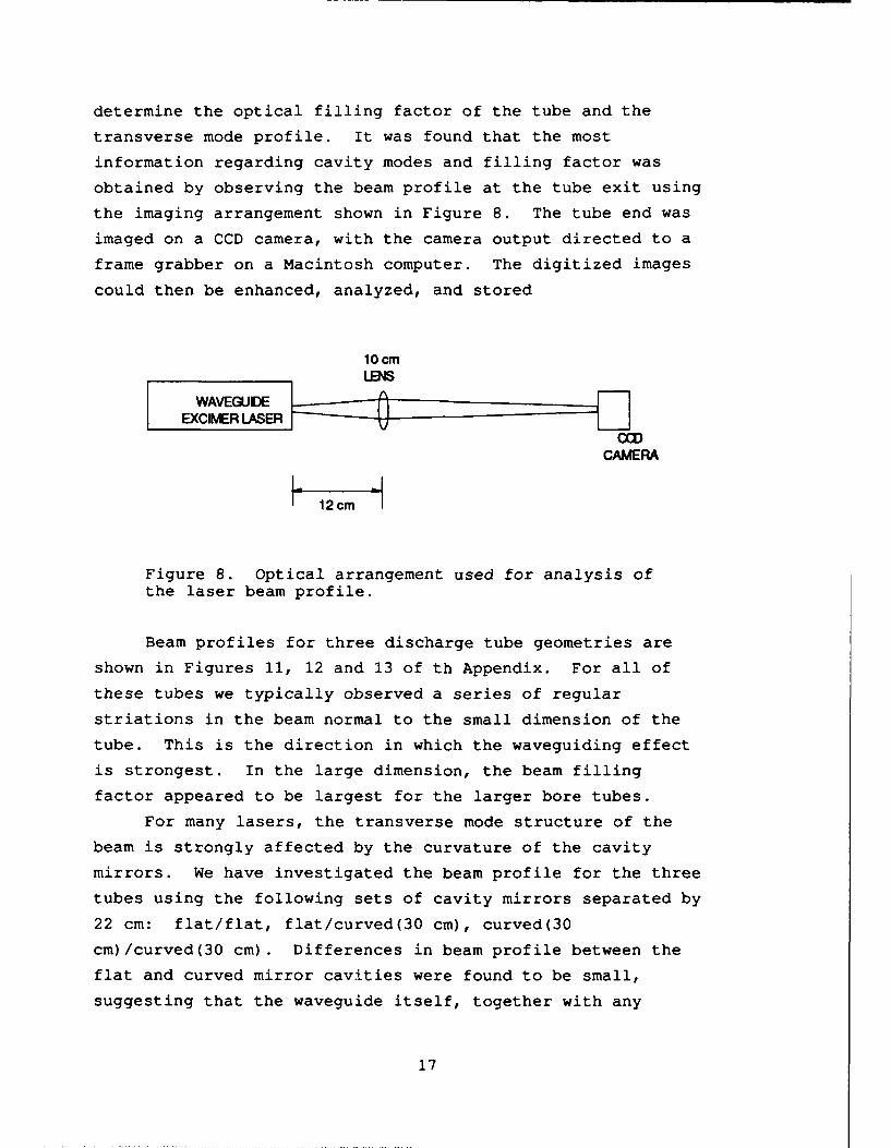
determine the optical filling factor of the tube and the
transverse mode profile. It was found that the most
information regarding cavity modes and filling factor was
obtained by observing the beam profile at the tube exit using
the imaging arrangement shown in Figure 8. The tube end was
imaged on a CCD camera, with the camera output directed to a
frame grabber on a Macintosh computer. The digitized images
could then be enhanced, analyzed, and stored
10 cmLENS
CAMERA
I 12cm
Figure 8. Optical arrangement used for analysis ofthe laser beam profile.
Beam profiles for three discharge tube geometries are
shown in Figures 11, 12 and 13 of th Appendix. For all of
these tubes we typically observed a series of regular
striations in the beam normal to the small dimension of the
tube. This is the direction in which the waveguiding effect
is strongest. In the large dimension, the beam filling
factor appeared to be largest for the larger bore tubes.
For many lasers, the transverse mode structure of the
beam is strongly affected by the curvature of the cavity
mirrors. We have investigated the beam profile for the three
tubes using the following sets of cavity mirrors separated by
22 cm: flat/flat, flat/curved(30 cm), curved(30
cm)/curved(30 cm). Differences in beam profile between the
flat and curved mirror cavities were found to be small,
suggesting that the waveguide itself, together with any
17

optical inhomogeniety in the active medium, have the
strongest influence on the transverse beam profile.
3.8. PERFORMANCE OF THE OPTIMIZED SINGLE TUBE LASER.
Using all of the information gleaned from the aboveexperiments, we constructed an optimized single tube laserthat could serve as a building block for a high power array.The laser emission is highly multimode, and the beam
divergence is approximately 9 times diffraction limit.
Although the beam quality of this device may not be suitablefor use in a coherent array, it has significant potential forpower scalability. A ten-element array based on this singleelement building block should be c: ±.ie of meeting the Phase
II goal of one watt of average power.
120/
100 - 0.5 x 2 mm tube
800
20
PRF
0 1
0 1000 2000
Figure 9. Average power as a function of pulse repetitionfrequency for an optimized single element module.
3.9. INFLUENCE OF WAVEGUIDING LOSS AND TRANSVERSE MODE
ON EFFICIENCY.
Efficiencies of approximately 0.4% have been measured
for the optimzed single tube lasers like that of Figure 9.Therefore, the efficiencies observed for the waveguide lasers
18

under investigation are as much as an order of magnitude
lower than other excimer systems. It is important to
understand the possible reasons for the reduced efficiency.
Section 3.9 above suggests that the problem lies with
optical cavity losses, and equations in that section can be
used to estimate the effect of losses in a XeCl laser of
known gain. Figure 10 shows calculated laser output energy
as a function of waveguide and mirror coupling losses for a
0.5 mm x 2 mm discharge tube 35 mm in length characterized by
a gain of 4% per cm. Note that output energy is strongly
influenced by cavity losses.
S400
XeCI Waveguide Laser3gain = 40/Scm, plasma loss - .250/ScmS300
LU 200
LUU)100
00.2 0.4 0.6 0.8 1.0 1.2 1.4
EXCESS CAVITY LOSS (%/cm)
Fig. 10. Effect of excess loss (waveguiding loss, mirrorcoupling loss, etc.) on a 0.05 x 0.2 x 35 cmwaveguide excimer laser with gain of 4%/cm andabsorption loss by plasma of .25%/cm. Reflectivityof output coupler is 80%.
Cavity losses of a few tenths of a per cent per
centimeter are adequate to reduce the laser output by factors
of 2 - 3. For the 0.5 mm x 2 mm x 35 cm tube modeled above
waveguiding and mirror coupling losses that average only
0.8%/cm are are consistent with the laser performance but are
adequate to reduce the output by a factor of 3. Similar
calculations have been carried out for a variety of other
tube geometries. Excess losses of the order of 1.0 - 1.2%/cm
19

have been found to be consistent with the measured laser
efficiency of the discharge tubes used in the beam quality
studies.
Waveguide excimer laser emission typically exhibits
both low and high divergence components. We have developed a
simple analysis based on geometric optics for estimating
waveguiding and mirror coupling losses as a function of beam
divergence in hollow waveguides. The analysis shows that
although 30 - 50% of the laser output is in a low divergence
mode the higher divergence components can exhibit very high
losses. We find that total average losses of 1 - 2%/cm are
consistent with the average divergence of the laser output.
These losses are about equally distributed between mirror -
waveguide coupling losses and waveguide transmission losses.
The above discussion suggests that waveguide
excimers are capable of efficient operation but that
excessive beam divergence can dramatically reduce laser
output energy and efficiency. An important source of high
beam divergence is curvature, bumps, and surface roughness in
the waveguide bore that scatter light from low order modes
into higher-order components. However, the laser gas is
excited at very high power levels during operation, and can
heat to several hundred degrees centigrade in less than one
microsecond. Nonuniform heating can lead to thermally-
induced optical distortions, or gas lens effects, that also
can act to excite high divergence modes. The small size of
the waveguide bore makes quantitative measurement of these
effects difficult, but it seems likely that both influence
laser performance.
3.10. A TWO ELEMZNT ARRAY.
As part of the Phase II effort, we constructed a two
element array. The array was constructed from two 0.5 mm
dia. x 20 cm discharge tubes excited by a single magnetron.
A profile of the nearfield array emission is shown in Fig. 14
of the Appendix. An energy of 17 gJ was obtained from the
20

array at a pulse repetition rate of 500 Hz. Although the
efficiency and energy obtained from the simple array was not
impressive, to our knowledge it is the only excimer laser
array that has been reported.
3.11. APPLICATION TO COMMERCIAL PRODUCTS.
Much of the microwave generation and discharge
technology described above is currently being transferred to
commercial lasers manufactured by Potomac Photonics. These
technical improvements will lead to commercial availablilty
of waveguide excimer lasers that are about one-half the size
of earlier units while at the same time generating higher
output power. As an added benefit the new lasers can be
constructed at lower cost. Although these systems emit a
highly multimode beam, their output is suitable for a large
number of applications. We believe that availablity of these
improved uv sources in the commercial marketplace will
stimulate development of new applications and could be an
enabling technology for several microfabrication and chemical
analysis systems.Manufacturing prototypes of one and two magnetron lasers
have been constructed and are undergoing final test. The
laser is capable of producing more than 150 mW of average
power at both 308 and 248 nm with pulse repetition rates
extending to 2 kHz.
21

SECTION 4
CONCLUSIONS
Issues associated with fabrication of coherent, high-
power uv laser arrays using waveguide excimer laser
technology have been investigated extensively. A single
element building block that could serve as the basis for a 10
element, one-watt array has been constructed. However, the
presence of high divergence transverse modes in the laser
cavity results in emission that is not suitable for use in
coherent arrays and also leads to high intracavity
waveguiding and mirror coupling losses that reduce laser
power and efficiency. The high divergence modes are believed
to to due to waveguide imperfections and gas lens effects.
They have been persistently evident in all devices
constructed to date.
In spite of problems in production of diffraction-
limited emission, the technology developed in Phase II has
potential utility in several industrial applications.
22

SZCTION 5
LIST OF REFIRENCzS
1. C. P. Christensen, B. W. Feldman, and R. Waynant, AppliedPhysics Letters, vol.46, p. 321(1985) [Unclassified].
2. R. S. Taylor, A. J. Alcock, and K. E. Leopold, OpticsCommunications, vol. 31, p. 197 (1979) [Unclassified].
3. V. N. Slinko, A. S. Sulakshin, and S. S. Sulakshin, SovietJournal of Quantum Electronics, vol. 18, p. 186 (1988)[Unclassified].
4. W. H. Long, Jr., and M. L. Bhaumik, Journal de Physique,vol. 40, pp. C7-127 (1979) [Unclassified].
5. L. A. Levin, S. E. Moody, E. L. Klosterman, R. E. Center,and J. J. Ewing, IEEE Journal of Quantum Electronics, vol.QE-17, p. 2282 (1981) [Unclassified].
23

APPENDIX
LASER BEAN PROFILES
Figure 11. CCD camera photograph of beam profile at tube endof 0.2 mm x 2 mm rectangular tube.
Figure 12. Beam profile at tube end for 0.5 mm x 1 mm tube.
A-i

Figure 13. Beam profile at tube end for 0.5 mm x 2 mm tube.
Figure 14. Emission pattern at array exit of 2 element arrayconstructed from 0.5 mm dia. tubes.
A-2

DISTRIBUTION LIST
DNA.TR-92-78
DEPARTMENT OF DEFENSE DEPARTMENT OF THE NAVY
DEFENSE NUCLEAR AGENCY NAVAL OCEAN SYSTEMS CENTER2 CYS ATTN: TITL ATTN: CODE 7402-T DR K BROMLEY
DEFENSE TECHNICAL INFORMATION CENTER NAVAL RESEARCH LJ.3ORATORY2 CYS ATTN: DTIC/FDAB ATTN: CODE 5554 F BARTOLI
STRATEGIC DEFENSE INITIATIVE ORGANIZATION OFFICE OF NAVAL RESEARCHATTN: DIRECTOR SENSORS ATTN: DR MATTHEW WHITEATTN: LT COL H SWENSONATTN: MR CARL NELSON DEPARTMENT OF DEFENSE CONTRACTORSATTN: TNS LTCOL B GUILMAIN KAMAN SCIENCES CORP
DEPARTMENT OF THE ARMY ATTN: DASIAC
HARRY DIAMOND LABORATORIES KAMAN SCIENCES CORPORATIONATTN: SLCHD-NW-TN DR H BRANDT 2 CYS ATTN: DASIAC
U S ARMY STRATEGIC SPACE & DEFENSE CMD POTOMAC PHOTONICS INCATTN: CSSD-AT-P S PROFFITT 2 CYS ATTN: C P CHRISTENSEN
Dist-1