definition and evaluation of a grout for … · definition and evaluation of a grout for...
TRANSCRIPT

1
DEFINITION AND EVALUATION OF A GROUT FOR CONSOLIDATION OF
ANCIENT MASONRY. SEISMIC VULNERABILITY OF A "PLACA"
BUILDING
Lisandra Câmara Miranda
DECivil, Instituto Superior Técnico, Universidade de Lisboa
June 2014
Abstract
The old masonry buildings constitute a large percentage of the building stock of Lisbon, and they are
generally exposed to a very high seismic risk due to the high probability of earthquake occurrence. The
“Placa” buildings are the last type of structures built in Lisbon which have masonry walls as structural
elements. The need for intervention in this type of structures is increasing, and it is necessary to identify
weaknesses and implement appropriate methods of rehabilitation.
This work presents an experimental campaign carried out to define and evaluate a grout appropriate to be
used in a technique of consolidation of ancient masonry structures: injecting grout. The evaluation of this
grout is made in terms of the characterization of their main properties, whether fresh, as in the hardened
state. Furthermore, the injection process and mechanical properties of grout are also analyzed. Moreover,
two rubble stone masonry specimens, with hydraulic lime mortar, were injected by above mentioned
grout, and tested by applying static cyclic horizontal displacements at the top.
Also, linear dynamic response spectrum analysis, where nonlinear behavior of the structure is taken into
account by means of a behavior coefficient, is presented. The numerical modeling of building structure
was defined with SAP2000. Additionally, the reinforcement of the building by the injection grout was
also implemented in the numerical model in order to see the efficiency of the strengthen technique (grout
injection).
1. Introdution
The “Placa” buildings were built in Lisbon between 1930s and 1960s, and correspond to the last building
typology which was built with masonry as a structural element. Furthermore, these buildings are also
included in the concept of ancient buildings, which were not designed according to the actual
requirements of structural safety. Currently, this typology still represents a significant part of the housing
stock.
The presence of the masonry walls of stone, brick and blocks of cement as structural elements is of great
importance in many old buildings, especially in “Placa” buildings. These walls are elements that can work
very well even before horizontal actions, since they are built and connected correctly. However, most of
these masonry buildings are in a high state of degradation and urgent intervention is required. In the
particular case of interventions in old buildings, the first option to be taken into account should be the
preservation of existing materials, if necessary by the spot repairs, or consolidation operations, while
preserving the integrity of the building. From the point of view of conservation, it is more appropriate to
use traditional materials and techniques, because of the aspects of compatibility, though it is not
appropriate exclude the use of new materials and new technologies.
One of the most used techniques for structural consolidation of masonry walls is the injection of fluid
grout, which being a passive technique that restores the integrity of the building and improves its strength.
This method of strengthening of old masonry buildings has been the target of several studies, particularly

2
with regard to the characteristics of grout used. The definition of fluid grout is an extensive process
because there are many tests that will be carried out in order to define the several characteristics of the
final product. One of the major concerns in creating this type of products (perhaps the most important) is
the choice of the materials, which have to provide compatibility with the materials constituting the
masonry walls, in order to performed reinforcement successfully.
The work of this dissertation is dedicated to the definition and evaluation of an injection grout for
strengthening of masonry walls, and the study of the seismic vulnerability of a “Placa” building (type
“Rabo de Bacalhau”), in its current and strengthen (injecting the grout) state.
2. Definition and Evaluation of an Injection Grout
2.1. Selection of Injection Grout
The grout used in consolidation of masonry walls should fill the existing voids and cracks, in order to
restore or increase the continuity of the wall, thus contributing to an increase of their mechanical
properties, in particular its strength, by restoring an adequate distribution of loads.
The selection of the grout was performed based on the requirements defined initially: flow time measured
by method of cone around 10±2 seconds; absence of exudation and volume variation; compressive
strength at 28 days of age, more than 20MPa.
After intense study of the multiple grouts with different compositions, the conclusion was that the grout
with a trace of 1:1 (cement:hydraulic lime), with 0.2% superplasticizer and a water/binder ratio of 0.45 is
the most appropriate grout. The constituent materials correspond to the natural hydraulic lime NHL5 and
pozzolanic cement CEM IV/B 32,5R, both of Secil, and the superplasticizer Viscocrete 225 of Sika.
2.2. Mixing procedure, tested grouts, cure conditions and methods
The grouts were made by adding the elements to the total dry mixing water, which was previously
drained into the mixing container. The mixture was held by a drill bit coupled to a drill, rotating at a
speed of 2700 rpm for 3 minutes.
The curing conditions chosen, T = 20±2ºC, RH (relative humidity) = 95±5%, were adapted from the
curing conditions described in the standard NP EN 445 (2008), for the characterization of cement grouts.
The characterization of the grout in the fresh state was carried out according to the NP EN 445 (2008)
and NP EN 447 (2008) standard. This characterization were evaluated the fluidity (cone and scattering
methods) and density immediately after production and for 30min after, and stability of the properties of
the grout for a period of 3 hours, with 30min intervals. During this period of time, the grouts were mixed
continuously.
The characterization of the grout in the hardened state was based on mechanical tests, according to the
standards NP EN 445 (2008), NP EN 447 (2008), NP EN 196-1 (2006) and NP EN 12390-3 (1999). In
this characterization the evaluation of the flexural and compression strengths of prismatic samples of
grout (40mm x 40mm x 160mm), compression strength of cubic samples (150mm edge) previously filled
with aggregate and injected by gravity with grout, and compression and diametral compression strength
of cylindrical samples (ϕ=42mm; h=330mm) resulting from the evaluation of the capacity of injection
under pressure was performed.
2.3. Evaluation of the Capacity of Injection
The capacity of injection by gravity was performed in cubic specimens, previously filled with a mixture
of aggregates, which have been selected taking into account the number of voids and the availability of
aggregates present in the laboratory. According to previous work (Sequeira, 2012), a mixture of two types
of calibrated available crushed stones were chosen (Crushed stone 1 with aggregates of dimensions
between 6mm and 12mm, and the Crushed stone 2 with aggregates of dimensions between 12mm and
3
20mm). In order to obtain a lower volume of voids, about 70% of Crushed stone 1 consider as an
appropriate and the remaining space (around 30% ) were filled by Crushed stone 2.
The evaluation of the ability of injection under pressure was performed based on the French standard NF
P 18-891 and to research work developed in this area (Almeida et al., 2012) (Brás and Henriques, 2012)
(Luso, 2012). The cylindrical specimens were filled by particles of dimensions calibrated. The grout is
injected through a reservoir, provided with a pressure control valve and a control manometer, connected
to a compressed air network. This reservoir is attached to the bottom of the column of injection through a
flexible tube with a diameter of 15 mm. Purging is carried out by the upper part of the column, by a
procedure similar to that connects between the reservoir ant the column.
2.4. Results and Discussion
The grout has a flow time around 14 seconds, and which does not present any variation of volume or
exudation, remaining homogeneous during 24 hours. For the compressive strength, it was possible to
reach strength of about 27MPa prismatic specimens.
The evaluation of the injection capacity of grout by gravity has shown that the grout under study has good
drainage characteristics, as well as a good ability to fill the voids present in the particle mixture. The
complete filling of each cube had an approximate duration of 30 seconds.
The evaluation of capacity injection under pressure allowed observing the behavior of the grout when
injected at low pressure in a porous medium. When using the gravel higher dimensions (4-6.3mm), the
grout took 7 seconds to fill the column. In another case, where a sand particle size of 2-4mm was used,
the filling time of the column was about 12 seconds.
The tests for assessing the ability of injection showed that fluidity was an important parameter in analysis
of the injectability capacity of given grout. After the compression test to the cubic specimens, it was
found that all the elements of crushed stone, introduced previously in the molds, were connected through
the grout injected by gravity. The same was verified for the case of cylindrical specimens, where the grout
was injected under low pressure. Thus, it is possible to conclude that the grout selected for the study
presents good penetrability in porous medium, since it presents a minimum percentage of voids, as well
as good connection between them.
3. Injecting Grout in Masonry Walls
3.1. Introduction
The evaluation of the characteristics of the grout defined to repair/reinforce structural elements and
structures should not be based only on the analysis of their properties. It is essential to evaluate their
effect on the structural elements where the grout is applied. Thus, the main objective in this section is to
assess the possible improvement of the mechanical properties of masonry walls after submitted to the
injecting grout.
For this purpose, two rubble stone masonry specimens, with hydraulic lime mortar, were subjected to the
process of injection of grout, being subsequently tested by applying cyclic horizontal displacements at the
top, following the main concepts found in ASTM (2002) and the work of Vasconcelos (2005). These
stone masonry specimens were built and evaluated following a research work carried out by Milosevic et
al. (2014) and developed in the framework of a national research project FCT (SEVERS project
www.severs.org). These specimens were repaired/reinforced with the selected grout, and subsequently
subjected to cyclic testing.
3.2. Injecting Grout
As already mentioned, specimens were tested first without any strengthening techniques (reference
specimens), in order to simulate ancient masonry walls, typical for the old buildings in Lisbon (such as

4
type “Placa” buildings). At the end of the test, the walls remained intact showing however a high level of
damage with a considerable percentage of cracks.
The injection tubes were placed in existing cracks (Figure 1), small openings being held whenever
necessary, with the aid a hammer and tool builder. Before placing the tubes, cleaning the holes was
performed by removing any dust inside. Subsequently transparent plastic tubes about 8 mm in diameter
were placed with a slight inclination in relation to the horizontal direction and a depth of 20 to 25cm.
Finally, the sealing of the tubes and the other existing cracks in the remaining re-closure wall were made
(Figure 2), with the mortar which has the same characteristics as mortar used in the construction of
reference walls. The placement of the injection tubes was carried out on both sides of each specimen,
trying to accomplish a triangular geometric distribution of the holes (Valluzzi, 2000). The spacing
between the tubes has not been constant since the dimensions of the stones are also variables. Other
smaller tubes were also placed, with air purge function.
Figure 1 – Placement of the
injection tube.
Figure 2 – Sealing the tube
and repointing of crack.
Figure 3 – Grout injecting by
gravity.
The injection was done by gravity on the masonry specimens (Figure 3), starting in the top line of the
tubes, passing into the next tube on the same horizontal line and thereby continuing progressively until
the lower row of tubes. The injection was given into each tube to be complete when it appeared that the
grout flowing through an adjacent tube.
3.3. Mechanical Characterization of Specimens
The tests were carried out with vertical load of 144kN, where the specimens were first subjected to a
vertical pre‐compression load which was kept constant, as much as possible, during the all test (Figure 4).
Vertically pre-stressed compressive load was applied through four steel bars (cables) (36kN per bar),
where each bar was equipped with a load cell capacity of 100kN each, which allowed measuring the
vertical load redistribution during the test. A rigid beam on the top of the specimen was used for the
uniform distribution of vertical loading from the actuator. A set of steel rollers on the top of the specimen
(Figure 4) allowed horizontal displacements of the top of the specimen with regard to the vertical
actuators. The vertical loads magnitude was defined based on the actual state of stresses of load bearing
walls in old Lisbon masonry buildings. After the vertical load applied, the horizontal load is transmitted
to the top of the wall by means of system steel plates that is appropriately strengthened with steel bars.
The horizontal force is recorded in the horizontal double acting hydraulic jack with capacity 300kN that is
linked to the reaction wall. In order to prevent sliding at the base, the specimens were fixed to a steel
profile and clamped down using steel beams, which was vertically presstressed (Figure 4).
The cyclic tests were conducted under displacement control by means of the horizontal LVDT connected
to the left side of the specimen, as can be seen in Figure 4. Each cycle was repeated three times with
monotonic increase of the maximum amplitude.

5
Figure 4 – Setup for cyclic shear test (Milosevic et al., 2014).
3.4. Experimental Results
The horizontal force-horizontal displacement diagrams provide valuable information on the lateral in-
plane behavior needed to evaluate the seismic performance of the walls. The horizontal force-horizontal
displacement diagram, for the two specimens are presented in Figure 5 and Figure 6, respectively. It
should be noted that the specimens designated as SR correspond to reinforced walls with grout injection,
being the specimens without any reinforcement designated by S.
The largest cracking, and the occurrence of cracks with a significant size, at the end of the test in the
specimen SR1, appeared at the bottom of the wall, which was expected situation, due to the fact that
existing cracks in the bottom of the specimen showed small opening, and in stage of repair/reinforcement
of wall S1 was not possible to inject grout in this zone.
a) b) Figure 5 – Horizontal force vs. Horizontal displacement: a) specimen SR1; b) specimen S1.
According to Figure 5, the force-displacement diagrams show the great similarity in behavior between the
two specimens (SR1 and S1), with a significant degradation in the wall SR1 when subjected to lateral
negative displacements (in the direction from left to right). This result is consistent with the behavior and
failure mode of this specimen, where there has been clearly a diagonal crack, revealing a shear behavior.
Regarding the overall strength of the specimen, a maximum total force of 136.5kN for the specimen S1,
and 130.1kN to the specimen SR1, was obtained, which makes a decrease of about 5%. As it was possible
to verify, these results show that with the injection of the studied grout was possible to recover the initial
strength of the structural element, after undergoing major damage.
Concerning the rigidity of the specimens, the unreinforced specimen (S1) presented an elastic stiffness of
17.3kN/mm, whereas for reinforced specimen (SR1) was 15.5kN/mm. The ductility was initially 7.4,
whereas for SR1 7.1 was obtained. The reduction verified for both parameters, before and after the
reinforcement applied, is insignificant, according what has already been said: the grout allowed the
specimen to recover almost all of their initial characteristics.
-120
-80
-40
0
40
80
-40 -30 -20 -10 0 10 20 30 40
Fo
rce (
kN
)
Displacement (mm)
-120
-80
-40
0
40
80
-40 -30 -20 -10 0 10 20 30 40
Fo
rce (
kN
)
Displacement (mm)
6
According to the cracking pattern presented and hysteretic cycles, as well as the calculation for each
cycle, the energy dissipation per cycle showed higher values for specimen SR1. However, the observed
differences between two specimens are small. Similarly, the changes in the values of the coefficient of
equivalent viscous damping, with increasing lateral displacement, are similar for both specimens.
Regarding the degradation of lateral stiffness, the values are very similar throughout the increment of
displacement, and also they showed the same development for both specimens.
At the end of the cyclic test, the specimen S2 did not present a considerable pattern of crack, because the
cracks which appeared were few and with small thickness. Therefore, this specimen would not provide
good results regarding the effect of the injected grout.
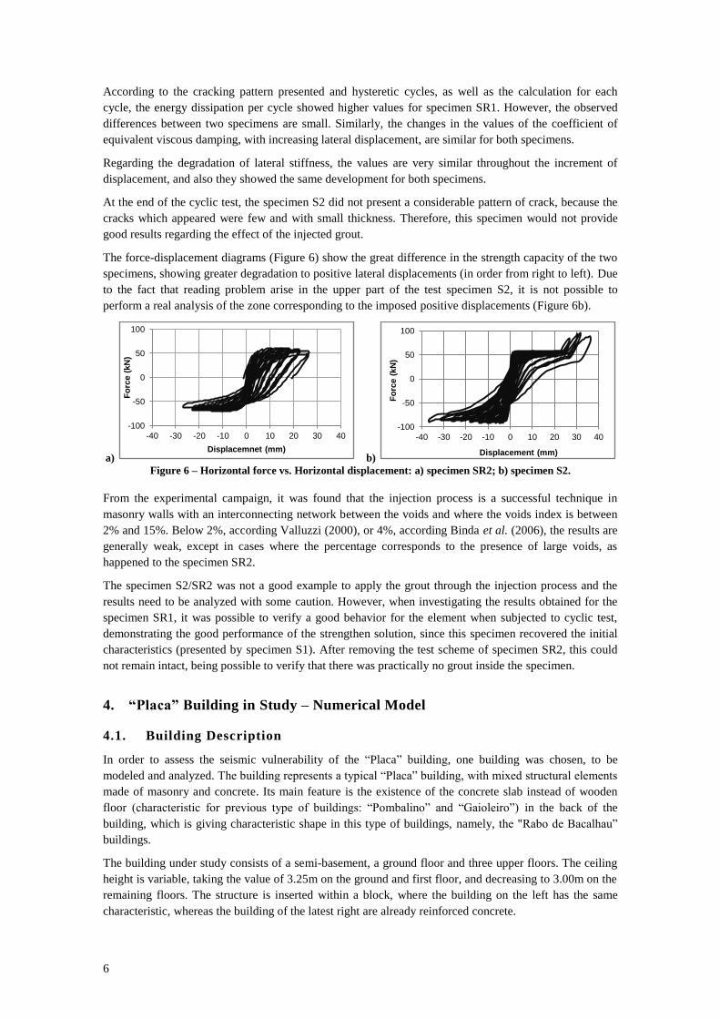
The force-displacement diagrams (Figure 6) show the great difference in the strength capacity of the two
specimens, showing greater degradation to positive lateral displacements (in order from right to left). Due
to the fact that reading problem arise in the upper part of the test specimen S2, it is not possible to
perform a real analysis of the zone corresponding to the imposed positive displacements (Figure 6b).
a) b) Figure 6 – Horizontal force vs. Horizontal displacement: a) specimen SR2; b) specimen S2.
From the experimental campaign, it was found that the injection process is a successful technique in
masonry walls with an interconnecting network between the voids and where the voids index is between
2% and 15%. Below 2%, according Valluzzi (2000), or 4%, according Binda et al. (2006), the results are
generally weak, except in cases where the percentage corresponds to the presence of large voids, as
happened to the specimen SR2.
The specimen S2/SR2 was not a good example to apply the grout through the injection process and the
results need to be analyzed with some caution. However, when investigating the results obtained for the
specimen SR1, it was possible to verify a good behavior for the element when subjected to cyclic test,
demonstrating the good performance of the strengthen solution, since this specimen recovered the initial
characteristics (presented by specimen S1). After removing the test scheme of specimen SR2, this could
not remain intact, being possible to verify that there was practically no grout inside the specimen.
4. “Placa” Building in Study – Numerical Model
4.1. Building Description
In order to assess the seismic vulnerability of the “Placa” building, one building was chosen, to be
modeled and analyzed. The building represents a typical “Placa” building, with mixed structural elements
made of masonry and concrete. Its main feature is the existence of the concrete slab instead of wooden
floor (characteristic for previous type of buildings: “Pombalino” and “Gaioleiro”) in the back of the
building, which is giving characteristic shape in this type of buildings, namely, the "Rabo de Bacalhau”
buildings.
The building under study consists of a semi-basement, a ground floor and three upper floors. The ceiling
height is variable, taking the value of 3.25m on the ground and first floor, and decreasing to 3.00m on the
remaining floors. The structure is inserted within a block, where the building on the left has the same
characteristic, whereas the building of the latest right are already reinforced concrete.
-100
-50
0
50
100
-40 -30 -20 -10 0 10 20 30 40
Fo
rce (
kN
)
Displacemnet (mm)
-100
-50
0
50
100
-40 -30 -20 -10 0 10 20 30 40
Fo
rce (
kN
)
Displacement (mm)

7
4.2. Structural Elements
The foundations are carried out continuously throughout the masonry walls, and their increased thickness
at the base for about double the thickness of the thickness walls. The foundations of the columns were
made of reinforced concrete.
In this building, four types of materials were used to build the walls. The exterior walls of the façade were
made of irregular stone masonry, verifying a progressive reduction of thickness in height. The gable walls
are made of masonry concrete blocks on every floor, except for the basement, where the walls are stone
masonry. For the interior walls, solid and hollow bricks masonry were used.
The reinforced concrete floor, present in the salient area, constituted by the bathrooms, kitchens and
bedrooms of the maids, consists of a thin slab of reinforced concrete (0.10m thickness). This slab has a
layer of longitudinal reinforcement in both directions in plan. The wooden floor is made up of wooden
beams (0.08m x 0.18m) spaced from 0.40m to 0.40m and they are tight by billets. The wooden floors are
supported directly on the exterior and interior walls and the overall thickness is about 0.30m.
The roof of the building consists of ceramic tiles, which are supported on a wooden structure that is
composed by a set of parallel trusses connected by purlins (main beams) and common rafters and slats.
The main staircase, situated in the center of the building, was built by a wooden structure to be
compatible with the wooden floor, while the secondary staircase was built in reinforced concrete.
4.3. Definition of the numerical model
4.3.1. Mechanical Characteristics and Mass definition
As referred, several materials (stone, hollow brick, solid brick and concrete block) were used to build the
walls of buildings. Moreover, reinforced concrete was defined in the model, particularly in terms of
density, modulus of elasticity, Poisson's ratio and damping coefficient.
For each wall, the value of the modulus of elasticity adopted in this work was an average value,
representative of the global behavior of the wall and not an isolated element of masonry. The
identification of this parameter was carried out with great caution, since it directly influences the dynamic
response of the building. Thus, the initial values adopted were based on the values presented in Italian
standard (NTC, 2008), since they result of an intensive study through various tests of existent walls.
According to the original design, the wooden floor was built by pine; and reinforced concrete structures
were built by the current concrete C15/20 and steel A235 (EC2-1, 2010). Thus, the characteristics of these
materials have been adopted in the model.
The value of the damping coefficient of 5% is considered for all materials (Branco, 2007) (Cardoso,
2002). Regarding the Poisson ratio, a value of 0.2 was adopted for all materials defined.
The building in study is still habitable, so not only was considered the dead loads of the building elements
but also the possible life loads (Table 1). The values of the masses were taken from the Descriptive
Memory (1943), Techniques Tables (Ferreira and Farinha, 1974) and the remainder bibliography (Branco,
2007) (Monteiro and Bento, 2012).
Table 1 – Weight distribution in the floor and roof.
Zone Dead Load
[kN/m2]
Remaining Permanent
Load [kN/m2]
Overload
[kN/m2]
Wood Floor 0.70 0.60 2.00
Concrete Slab 2.40 0.60 2.00
Roof Wood 1.20 0.60 0.40

8
4.3.2. Structural Elements
The modeling of the building was carried out using various existing finite element in the commercial
program SAP2000 (SAP2000, 2011).
Masonry walls of the building were modelled as shell-thick elements, whereas the beams and columns
were modelled as frame elements. For the walls it is assumed plate behavior, so modification factor are
applied, close to zero, which affect the moments m11, m12 and m22 and shear forces v13 and v23.
The modeling of wood floor was performed through a mesh frame elements, simulating the wooden
beams of the floor. The floor beams were arranged in a direction perpendicular to the main façade.
Despite the reduced thickness presented by concrete slab, and although some authors have disagreement
that in such cases, the behavior of the floor in its plan cannot be regarded as rigid, the slab was modeled
by a rigid diaphragm. Thus, it was assumed that these floors do not have axial deformations and
distortions in the plan, although they may have displacements perpendicular to the plane.
The foundations were fully restrained, which seems to be a reasonable solution because through the years
go by the soil has probably already been consolidated.
The structure of the roof was not considered in the model. However it was considered the influence of its
mass in the dynamic analysis. Furthermore, it is important to refer that both stairs (main and the
secondary) were not modeled once the first is constructed of wood and the second is made of concrete
and it is in the outer contour of the building. Moreover, the decorative elements of the façade and the
balconies also were not considered in the model.
4.4. Calibration of the numerical model
The calibration of the model developed in SAP2000 was based on the results obtained with the
experimental tests developed with the proper equipment for the dynamic characterization of the building
(Oliveira, 1997) (Oliveira and Navarro, 2010). Thus, from the fundamental frequencies and modes of
vibration, it was possible to carry out corrections in the model, trying to bring the model results close to
those obtained experimentally.
In the calibration process, the values of the modulus of elasticity of the masonry walls, were essentially
changed, taking into account the positioning of the different walls, in order to understand which ones
would have the greatest influence in the two main orthogonal directions. On the other hand, as the seismic
behavior of a structure depends also of its intrinsic characteristics and the interaction with the
surroundings (Lopes et al., 2008), the calibration of the isolated structure would not be enough to reach
adequate values. Thus, the modeling of adjacent buildings were necessary, in order to ensure the effect of
the block (Figure 7).
After consideration of several hypotheses, the last attempt made in the calibration of the model took the
values for the mechanical properties of the materials presented in Table 2.
Figure 7 – Numerical model with adjacent
buildings, in Y-direction.
Table 2 – Properties of materials.
Material of
Masonry
[kN/m3]
E
[GPa]
Stone 21 1.80
Hollow brick 12 1.10
Solid brick 18 1.60
Cement block 14 2.00

9
Table 3 presents the comparative results between the two models tested (isolated model and the set of
three buildings), where it is possible to check the proximity of the fundamental frequency values obtained
with the models in the X and Y directions with the corresponding experimental values.
Table 3 – Comparison between fundamental frequencies of models and experimental tests.
Description X-Direction Y-Direction Error X Error Y
Experimental 4.10 Hz 4.30 Hz - -
Isolate Model 3.32 Hz 4.50 Hz 19% 5%
Aggregate Buildings 3.70 Hz 4.50 Hz 10% 5%
4.5. Dynamic Properties
The first 100 modes of vibration were analyzed and it was concluded that there is, in general, low mass
participation in most of them. The characteristics of the first six vibration modes are depicted in Table 4.
Table 4 – Frequencies and mass participation of the main modes of vibration of the building model.
Modes Period
[s]
Frequency
[Hz]
Mass Participation
UX [%] UY [%] UX [%] UY [%]
1 0.27 3.70 56.6 0.0 56.6 0.0
2 0.23 4.41 0.0 0.8 56.6 0.8
3 0.22 4.50 0.0 13.9 56.6 14.7
4 0.22 4.50 0.0 0.1 56.6 14.8
5 0.22 4.53 0.0 0.9 56.6 15.8
6 0.22 4.65 0.0 17.9 56.6 33.7
With regard to the dynamic characteristics of the analyzed model, it can be seen from Table 4 the first six
vibration modes, define in terms of periods, frequencies and modal mass participations in both horizontal
directions, in the elastic stage of response.
As expected, the first vibration mode (Figure 8) was mostly characterized by the translation movements
along the X direction. It can be observed that the second vibration mode has a low contribution to the
global behavior. The third vibration mode (Figure 9) has a significant mass participation along Y
direction, and it is characterized by the translation movements along this direction.
Figure 8 – First vibration mode.
Figure 9 – Third vibration mode.
The slab of reinforced concrete is not working as a continuous slab, and it is present only in the salient
area of the building. Thus, this slab is not contribute to the increase in overall strength of the structure, but
has a contribution in increasing vulnerability of the building. The concrete slab is supported just in
masonry walls, not even having any impediment to movement at the level of their plan, since the adjacent
buildings only have a contact on the front part of the building. This difference of stiffness, as well as the
boundary conditions, gives huge problems of rotation structure, since there is a greater rotation according
to the vertical direction, being in agreement with that obtained in modeling, that is, there are no pure
translational modes.

10
5. Safety verification
5.1. Seismic Action Definition
The definition of the seismic action was performed by an elastic acceleration response spectrum
according to EC8 (2010).
The building belongs to the class of common importance of buildings. According to the EC8 (2010), they
are belonging to the importance class of II. According to the geological area conditions, the soil type is
classified as B. Attending to the seismic action defined in Portuguese National Annex of the EC8 (NA
EC8-1, 2010), some values which characterize both response spectra, for this analyzed building, are
presented in Table 5. Consequently, the design spectra are defined, as shown in Figure 10.
Table 5 – Parameters for defining the response spectra.
Seismic Zone Smax TB (s) TC (s) TD (s) agR (m/s2) Iγ ag (m/s2) S
1.3 1.35 0.10 0.60 2.00 1.50 1.00 1.50 1.29
2.3 1.35 0.10 0.25 2.00 1.70 1.00 1.70 1.27
Figure 10 – The design spectra for both earthquakes.
Regarding the behavior factor (q), the value of 1.5 is adopted in accordance with EC8 (2010), which
defines this minimum value of q for structures with low energy dissipation.
It can be seen, from Figure 10, that the spectrum type 2 is more harmful than the spectrum type 1, for the
fundamental frequencies, meaning that is the one considered along the seismic evaluation of this building.
5.2. Combination of Actions
The safety verification is defined for two combinations of actions, where the seismic action and the
overload as base variables, respectively, defined according to EC0 (2009):
1
,,2
1
,""""
i
ikiEd
j
jkQAG (1)
1,1,
1
,,""
kQ
j
jkjGQG
(2)
where:
Gk,j – characteristic value of the permanent action j;
AEd – design value of seismic action;
Qk,i – characteristic value of the variable action i;
Qk,1 – characteristic value of variable action base combination 1;
2,i – factor for quasi-permanent of the variable action i (2 =0.3);
jG, – partial factor for the permanent action j 35.1
G ;
1,Q – partial factor for the variable action base combination 1 50.1
Q ;
0,00
1,00
2,00
3,00
4,00
5,00
0,00 1,00 2,00 3,00 4,00
Sd (
m/s
2)
T (s)
Sismo Tipo 1
Sismo Tipo 2
1º Modo
3º Modo
11
In this study, the SRSS method (Square-Root-of-Sum-of-Squares) is used to calculate the maximum value
of the seismic action’s effect and it corresponds to the square root of the sum of the squared values of the
action effect due to both horizontal components. In terms of combination of the modal responses, it was
used the Complete Quadratic Combination (CQC).
5.3. Safety assessment
The analysis of results of the building under study involves the analysis of vertical and shear stresses
present in the walls of the structure, due to the two combinations of actions defined. It is essentially
studied shear average strength to the alignments of the walls according to the main directions (X and Y),
where the alignments in which the average shear strength is deficient is identified. The verification of the
safety of reinforced concrete linear elements is also performed.
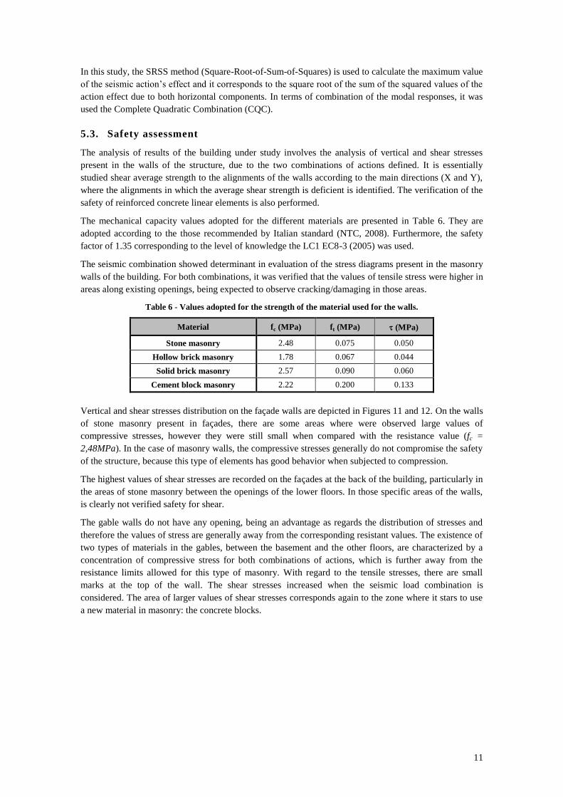
The mechanical capacity values adopted for the different materials are presented in Table 6. They are
adopted according to the those recommended by Italian standard (NTC, 2008). Furthermore, the safety
factor of 1.35 corresponding to the level of knowledge the LC1 EC8-3 (2005) was used.
The seismic combination showed determinant in evaluation of the stress diagrams present in the masonry
walls of the building. For both combinations, it was verified that the values of tensile stress were higher in
areas along existing openings, being expected to observe cracking/damaging in those areas.
Table 6 - Values adopted for the strength of the material used for the walls.
Material fc (MPa) ft (MPa) (MPa)
Stone masonry 2.48 0.075 0.050
Hollow brick masonry 1.78 0.067 0.044
Solid brick masonry 2.57 0.090 0.060
Cement block masonry 2.22 0.200 0.133
Vertical and shear stresses distribution on the façade walls are depicted in Figures 11 and 12. On the walls
of stone masonry present in façades, there are some areas where were observed large values of
compressive stresses, however they were still small when compared with the resistance value (fc =
2,48MPa). In the case of masonry walls, the compressive stresses generally do not compromise the safety
of the structure, because this type of elements has good behavior when subjected to compression.
The highest values of shear stresses are recorded on the façades at the back of the building, particularly in
the areas of stone masonry between the openings of the lower floors. In those specific areas of the walls,
is clearly not verified safety for shear.
The gable walls do not have any opening, being an advantage as regards the distribution of stresses and
therefore the values of stress are generally away from the corresponding resistant values. The existence of
two types of materials in the gables, between the basement and the other floors, are characterized by a
concentration of compressive stress for both combinations of actions, which is further away from the
resistance limits allowed for this type of masonry. With regard to the tensile stresses, there are small
marks at the top of the wall. The shear stresses increased when the seismic load combination is
considered. The area of larger values of shear stresses corresponds again to the zone where it stars to use
a new material in masonry: the concrete blocks.

12
a) Alignment C
b) Alignment 1
c) Alignment 2
Figure 11 – Vertical stresses present on the façade walls due to the seismic load combination (kPa).
a) Alignment C
b) Alignment 1
c) Alignment 2
Figure 12 – Shear stresses present on the façade walls due to the seismic load combination (kPa).
The reinforced concrete columns were modeled at the level of the balconies present on the back of the
building. Thus, it is expected to exhibit considerable effort since they are not wrapped in masonry walls,
which would absorb large percentage of load. The two columns have equal square section with 0.20m
edge, and 4 bars 3/8'' longitudinal reinforcement (As = 2.85cm2). With bending moment and axial force
condition in each column, the reinforcement necessary to the safety assessment has been determined. Due
to this can be concluded that the columns are very stressed, and thus they need more reinforcement to
verify the safety condition.
For the reinforced concrete beams (existing in the basement), the dimensions, the longitudinal
reinforcement (As) and the acting (MSd) and resistant (MRd) moments are presented in the Table 7. The
values show that the beams are bending safety. The transverse reinforcement is the same in all the beams
(1.06cm2/m), and it may not be enough for the safety assessment of these elements to the shear. This fact
would be expected, since, according to some literature, the transverse reinforcement in reinforced
concrete elements present in old buildings are often insufficient.
Table 7 – Dimensions and reinforcement of the reinforced concrete beams.
Beam b (m) h (m) As MRd (kNm) MSd,máx (kNm)
V1 0.25 0.40 1/4'' 9.41 8.69
V2 0.30 0.50 3/4'' 99.40 74.23
V3 0.20 0.40 1/2'' 35.31 27.04
5.4. Analysis of Results of Structure subject to Consolidation of Masonry Walls
The gable walls were the elements with determinant diagrams of stresses, particularly for shear stresses.
In order to verify the effect of the injection of grout, treating it as a more local reinforcement, it was
13
decided to increase the rigidity of the gable walls, taking into account the results obtained from cyclic
tests presented previously.
The increased resistance of the walls, after injection of grout, was determined from the comparison
performed essentially between the values obtained at the end of the test walls without reinforcement and
those obtained at the beginning of the test of the reinforced walls. This analysis allowed us to conclude
that there was an increase of about 20% of its stiffness, which was used to define new material of the
gable walls on the adopted model.
The new model did not present differences of their modal characteristics. The new stresses observed show
slightly higher values. The floors of the “Placa” buildings have not both, a complete flexible or complete
rigid behavior in plan; thus the forces of inertia resulting from seismic action absorbed by each masonry
wall are also affected by the rigidity of the walls. The increase of stiffness of the reinforced building
meant that the gable walls absorb greater efforts, reaching higher values of stresses.
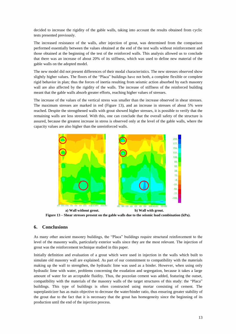
The increase of the values of the vertical stress was smaller than the increase observed in shear stresses.
The maximum stresses are marked in red (Figure 13), and an increase in stresses of about 5% were
reached. Despite the strengthened walls with grout showed higher stresses, it is possible to verify that the
remaining walls are less stressed. With this, one can conclude that the overall safety of the structure is
assured, because the greatest increase in stress is observed only at the level of the gable walls, where the
capacity values are also higher than the unreinforced walls.
a) Wall without grout.
b) Wall with grout.
Figure 13 – Shear stresses present on the gable walls due to the seismic load combination (kPa).
6. Conclusions
As many other ancient masonry buildings, the “Placa” buildings require structural reinforcement to the
level of the masonry walls, particularly exterior walls since they are the most relevant. The injection of
grout was the reinforcement technique studied in this paper.
Initially definition and evaluation of a grout which were used in injection in the walls which built to
simulate old masonry wall are explained. As part of our commitment to compatibility with the materials
making up the wall to strengthen, the hydraulic lime was used as a binder. However, when using only
hydraulic lime with water, problems concerning the exudation and segregation, because it takes a large
amount of water for an acceptable fluidity. Thus, the pozzolan cement was added, featuring the outset,
compatibility with the materials of the masonry walls of the target structures of this study: the “Placa”
buildings. This type of buildings is often constructed using mortar consisting of cement. The
superplasticizer has as main objective to decrease the water/binder ratio, thus ensuring greater stability of
the grout due to the fact that it is necessary that the grout has homogeneity since the beginning of its
production until the end of the injection process.

14
An evaluation of the injection capacity of grout in porous medium was also performed, either by gravity,
or under pressure. In both tests, the grout showed good penetration capacity, filling all the existing voids
in the samples (cubic and cylindrical).
In the next stage, the assessment of the effectiveness of technical consolidation of masonry walls through
the injection of the grout is studied. Two masonry specimens of limestone were subjected to the injecting
grout, being subsequently tested by applying static horizontal load at the top. The injection was carried
out on the specimens after being subjected to the same cyclic test, where each one shows a distinct
cracking pattern. The results obtained have shown that the higher amount of grout injected, that is, the
better the penetration of grout inside a particular masonry, what is following to obtained better
characteristics regarding to the strength and stiffness of the specimen. The results of the performed test
(cyclic test) showed that the injection of grout studied allowed, in general, recovering the initial
characteristics of masonry structural elements.
Afterward, a real case of an ancient building of type "Placa" was studied, which has a particular
characteristic, giving it the name "Rabo de Bacalhau". In order to resemble as much as possible modeling
with actual building, the model calibration was performed and based on the results obtained from the
experimental tests.
The safety assessment of the building helped to identify the areas of greatest structural vulnerability
following the level of seismic safety regulations of EC8 (2009) and the limits of strength considered. The
safety assessment was performed taking into account the loads present in the reinforced concrete linear
elements, as well as the stress diagrams in the masonry structural elements.
Finally, in order to evaluate the process of consolidation of masonry walls, based on the study carried out
in this work, a new model of the building was analyzed. In this new model, the characteristics of the gable
walls are changed, where more strength was obtained and the seismic safety reached.
References
Almeida, N. G.; Ferreira Pinto, A. P.; Gomes, A.; Gonçalves, N. – Caldas de injecção para alvenarias
antigas. Fluidez versus capacidade de Injecção. Construção 2012, Portgal.
ASTM E 2126-02a Standard test methods for cyclic (reversed) load test for shear resistance of walls for
buildings. ASTM international. West Conshohocken, PA 19428-2959.
Binda, L.; Salsi, A.; Tedeschi, C. – Compatibility of materials used for repair of masonry buildings:
research and applications, Fracture and Failure of Natural Building Stones-Applications in the
Restoration of Ancient Monuments, Part I, Stavros k. Kourkoulis Editor, 2006, Elsevier.
Branco, M, – Reforço Sísmico de Edifícios de Alvenaria. Aplicação a edifícios “Gaioleiros”. Dissertação
de Mestrado em Engenharia Civil, Instituto Superior Técnico, Outubro 2007, Lisboa.
Brás, A.; Henriques, F. – Natural hydraulic lime based grouts.The selection of grout injection parameters
for masonry consolidation, Construction and Building Materials Journal 26, 2012, pp. 135-144.
Cardoso, M. R. – Vulnerabilidade Sísmica de Estruturas Antigas de Alvenaria: Aplicação a um Edifício
Pombalino. Dissertação de Mestrado em Engenharia Civil, IST, Outubro 2002, Lisboa.
Memória Descritiva do projecto do edifício – Arquivo Municipal de Lisboa: Obra n.º 3402, Referência:
PT/AMLSB/CMLSB/UROB-OP/01/03026 – Rua Augusto Gil, 10.
Eurocódigo 0: Bases para o projecto de estruturas. NP EN1990:2009, CEN, Bruxelas, 2009.
Eurocódigo 2: Projecto de estruturas de betão - Parte 1-1: Regras gerais e regras para edifícios. NP EN
1992-1-1, CEN, 2010.
Eurocódigo 8: Projecto de estruturas para resistência aos sismos - Parte 1: Regras gerais, acções
sísmicas e regras para edifícios, Anexo Nacional. NA. NP EN 1998-1, CT115 (LNEC), Lisboa, 2010.
Eurocódigo 8: Projecto de estruturas para resistência aos sismos - Parte 1: Regras gerais, acções
sísmicas e regras para edifícios. NP EN 1998-1:2010, CT115 (LNEC), Lisboa, 2010.
Eurocode 8: Design of structures for earthquake resistance - Part 3: Assessment and retrofitting of
buildings. CEN (ENV 1998-3), 2005.
15
Ferreira, V.; Farinha, B. – Tabelas Técnicas, 4ª ed., Instituto Superior Técnico, 1974, Lisboa.
Lopes, M.; et al. – Sismos e Edifícios. 1.ª Edição, Edições Orion, Julho 2008, Lisboa.
Luso, E. – Análise Experimental de Caldas à Base de Cal para Injeção de Alvenaria Antiga. Tese de
Doutoramento em Engenharia Civil, Universidade do Minho, 2012, Guimarães.
Milosevic, J.; Lopes, M.; Bento, R.; Gago, A. S. – Experimental Study of Rubble Stone Masonry
Specimens, 9.ª Conferência Internacional de Alvenaria, 2014, em Guimarães (para publicação).
Monteiro, M.; Bento R. – Seismic Assessment of a “Placa” Buildings. Relatório ICIST DTC Nº 20,
ICIST/IST, Outubro 2012, Lisboa.
Norma Portuguesa EN 12390-3 – Testing hardened concrete. Part 3: Compressive strength of test
specimens, CEN, 1999, Bruxelas.
Norma Portuguesa EN 196-1 – Métodos de ensaio de cimentos. Parte 1: Determinação das resistências
mecânicas, IPQ, 2006).
NP EN 445 – Caldas de injecção para armaduras de pré-esforço: Métodos de ensaio, IPQ, 2008.
NP EN 447 – Caldas de injecção para armadura de pré-esforço: Requisitos básicos, IPQ, 2008.
Norme Tecniche per le Costruzioni. 14/1/2008, Official Bullettin no. 29 of February 4, 2008.
Oliveira, C. S. – Frequências próprias de estruturas com base em medições in-situ. 3.º Encontro sobre
Sismologia e Engenharia Sísmica, Instituto Superior Técnico, 1997, Lisboa.
Oliveira, C.S.; Navarro, M. – Fundamental periods of vibration of RC buildings in Portugal from in-situ
experimental and numerical techniques. Bulletin of Earthquake Engineering, V. 8, pp. 609-642, 2010.
SAP2000 – Computers & Structures Inc. CSI Analysis Reference Manual For SAP2000, ETABS, and
SAFE. 2011.
Sequeira, J. – Estudo de Caldas de Injecção Comerciais para Alvenarias Antigas, Dissertação de
Mestrado, Instituto Superior Técnico, Universidade Técnica de Lisboa, Outubro 2012.
Valluzzi, M. – Comportamento Meccanico di Murature Consolidate Con Materiali e Tecniche a Base di
Calce, Tesi de Dottorato, Universita Degli Studi di Trieste, 2000.
Vasconcelos G. – Experimental investigations on the mechanics of stone masonry: characterization of
granites and behaviour of ancient masonry shear walls, PhD, Universidade do Minho, 2005.