definity g3 system - textfiles.com
TRANSCRIPT

AT&T 555-230-500Issue 1, January 1992
DEFINITY® Communications SystemGeneric 1 & Generic 3
System Management

Copyright © 1991 AT&TAll Rights ReservedPrinted in U.S.A
NoticeWhile reasonable efforts were made to ensure that theinformation in this document was complete and accurateat the time of printing, AT&T can assume no responsibilityfor any errors. Changes and corrections to theinformation contained in this document may beincorporated into future reissues.
Your Responsibility for Your System’s SecurityYou are responsible for the security of your system.AT&T does not warrant that this product is immune fromor will prevent unauthorized use of common-carriertelecornmunication services or facilities accessed throughor connected to it. AT&T will not be responsible for anycharges that result from such unauthorized use. Productadministration to prevent unauthorized use is yourresponsibility and your system administrator should readall documents provided with this product to fullyunderstand the features available that may reduce yourrisk of incurring charges.
Federal Communications Commission (FCC)StatementThis equipment generates, uses, and can radiate radio-frequency energy and, if not installed and used inaccordance with the instruction manual, may causeinterference to radio communications. It has been testedand found to comply with the limits for a Class Acomputing device pursuant to Subpart J of Part 15 of FCCRules, which are designed to provide reasonableprotection against such interference when operated in acommercial environment.
Operation of this equipment in a residential area is Iikelyto cause interference, in which case the user at his/herown expense will be required to take whatever measuresmay be required to correct the interference.
TrademarksDEFINITY is a registered trademark of AT&T. In thisdocument, DEFINITY Communications System Generic 3is often abbreviated to DEFINITY Generic 3 or Generic 3.
DEFINITY Communications System Generic 1 is oftenabbreviated to DEFINITY Generic 1 or Generic 1.
AcknowledgmentThis document was prepared by the AT&T TechnicalPublications Department Middletown NJ.

Contents
CHAPTER 1. INTRODUCTION ................................................................................................................. 1-1
Overview ...................................................................................................................................... 1-1
System Management ........................................................................................................................... 1-1
Initialization ....................................................................................................................................................... 1-2
Ongoing Administration .............................................................................................................................. 1-2
Record Keeping ........................................................................................................................................................... 1-2
When to Use This Manual ........................................................................................................................................... 1-3
Organization .............................................................................................................................................................. 1-3
Conventions Used in This Document .............................................................................................1-4
CHAPTER 2. DEFINITY ADMINISTRATION TERMINALS .........................................
Overview ..............................................................................................................
715 MT Terminal ....................................................................................................
......... 2-1
........ 2-1
......... 2-3
513 BCT Keyboard ............................................................................................................ 2-4
How to Program the Function Keys for a 513 BCT .................................................................. 2-11
4425, 4410, 610, and 615 MT Terminals .............................................................................................. 2-15
AT&T PC 6300 Keyboard ............................................................................................................. 2-15
CHAPTER 3. SYSTEM ADMINISTRATION ...............................................................3-1
Administration Sequence .................................................................................................... 3-1
CHAPTER 4. ADMINISTRATIVE TASKS—SYSTEM .......................................................4-1
How to Log In and Log Off ........................................................................................ 4-1
How to Change Your Password ....................................................................................................... 4-3
How to Set Up the System to Allow Remote Administration ....................................................... 4-4
How to Administer the System From a Remote Location ............................................................ 4-6
How to Administer Netcon Channels ................................................................................................. 4-6
i

How to
How to
How to
How to
Administer Dial Plan and Feature Access Codes ................................................................ 4-8
Set Date and Time ....................................................................................................................... 4-10
Print on Demand ......................................................................................................................... 4-13
List History ................................................................................................................... 4-13
CHAPTER 5. ADMINISTRATIVE TASKS—VOICE TERMINAL ...................................... 5-1
How to Administer Voice Terminals ...................................................................................................... 5-1
How to Administer Voice Terminals Without Hardware ...................................................................... 5-8
How to Administer Data Modules and Voice Terminal Adjuncts .................................................... 5-9
CHAPTER 6. HARDWARE RECONFIGURATION ................................................................ 6-1
Overview .................................................................................................................................................. 6-1
Circuit Pack Administration ..................................................................................................................... 6-2
CHAPTER 7. SYSTEM BACKUP FOR DEFINITY G1 AND G3i ............................ 7-1
Save Translation ...............................................................................................................................................7-1
Save and Restore Recorded Announcements ................................................................................. 7-1
Tape Backup for a System Without the Duplication Option ...................................................... 7-2
Tape Backup for a System With the Duplication Option .............................................................. 7-4
Tape Errors ....................................................................................................................... 7-6
CHAPTER 8. SYSTEM BACKUP FOR DEFINITY G3r ........................................................8-1
Overview .................................................................................................................................... 8-1
Save Announcements Command ................................................................................................... 8-2
Restore Announcements Command ................................................................................................. 8-5
Error Conditions ....................................................................................................... 8-7
Save Translation Command ......................................................................................................... 8-9
Backup Command ................................................................................................................ 8-13
Restore Command .............................................................................................................................. 8-15
Error Conditions ......................................................................................................................................... 8-17
ii

CHAPTER
CHAPTER
9. REFERENCES ......................
10. ABBREVIATIONS AND
..................................................................... 9-1
ACRONYMS ....................................................... 10-1
GLOSSARY .................................................................................................................. G-1
INDEX .................................................................................................................................. I-1
iii

Figures
Figure 2-1.
Figure 2-2.
Figure 2-3.
Figure 2-4.
Figure 2-5.
Figure 2-6.
Figure 2-7.
Figure 2-8.
Figure 2-9.
Figure 4-1.
Figure 4-2.
Figure 4-3.
Figure 5-1.
Figure 5-2.
Figure 7-1.
Figure 7-2.
Figure 7-3.
Figure 7-4.
Figure 8-1.
Figure 8-2.
Figure 8-3.
715 MT Keyboard .................................................................................. 2-3
513 BCT Keyboard Function Keys and Programmable Keys . . . . . . . . . . . . . . . . . . . . . . . . . . . 2-10
Screen Labels Displayed When the LCL MENU Key is Pressed on a 513 BCT .... 2-12
Screen Display When the USER PF SET-UP Key is Pressed on a 513 BCT ......... 2-13
Assigning Administrative Functions toProgrammable Function Keys (F1, F2, and F3) on a 513 BCT .................................. 2-14
4425 Keyboard Assignments ..................................................................................... 2-16
4410 Keyboard Assignments ................................................................................... 2-17
610 MT Terminal Keyboard Assignments .................................................................... 2-18
615 MT Keyboard Assignments Used Without a 513 Emulation Cartridge ............... 2-19
Password Change Screen Form .............................................................................................. 4-4
Date and Time Screen Form ......................................................................... 4-10
Typical History Form ....................................................................................................... 4-14
Duplication Station Form Without a Data Module ......................................................... 5-6
Duplication Station Form With a Data Module .......................................................... 5-6
Save Translation—SPEA ....................................................................................... 7-2
Save Announcements Screen—SPEA ........................................................................... 7-3
Save Translation—SPE_B .......................................................................................... 7-4
Save Announcements—SPE_B ............................................................................... 7-5
Save Translation Completion Status ............................................................................... 8-11
Backup Completion Station ...................................................................................................... 8-14
Restore Completion Status ........................................................................................................ 8-16
Tables
Table 2-A. Terminal Keys ...................................................................................................... 2-5
Table 2-B. Escape Sequences .................................................................................................... 2-15
Table 4-A. Conversion to 24-Hour Clock .............................................................................. 4-12
Table 8-A. Save Translation Command Error Codes ........................................................... 8-11
iv

CHAPTER 1. INTRODUCTION
CHAPTER 1. INTRODUCTION
Overview
This manual provides the information necessary for the System Manager to administer theDEFINITY® Communications System Generic 1 and Generic 3 using any of the administrationterminals listed in Chapter 2. If system administration will be performed using the DEFINITY®Communications System Generic 3 Management Applications (G3-MA), refer to DEFINITY®Communications System Generic 3 Management Applications—Operations, 585-229-202, forsystem management procedures. Unless otherwise noted, the DEFINITY Communications Sys-tem will be referred to as the “system” throughout this document.
During the planning process, system requirements were identified by the Account Team and yourcompany. Those requirements were converted into orderable system hardware when the AccountTeam configured the system. Those features were assigned on a system and per-terminal basisusing the forms in the appropriate DEFINITY® Communications System Implementation manualfor your DEFINITY System.
The forms in your Implementation manual provide an accurate representation of the screens thatare displayed on the system administration terminal. The forms are a blueprint showing how thesystem and voice terminal features should be constructed.
In order to administer the system, the following must first be done:
● Attend the System Customer Training Course.
● Be familiar with the information in the DEFINITY® Communications System Generic 1
and Generic System 3—Description, 555-230-200, and the DEFINITY CommunicationsSystem Genetic 1 and Generic 3—Feature Description, 555-230-201.
● Obtain a list from the Account Team and determine what hardware has been ordered.
● Using your Implementation manual, complete:
– the Communications Survey
– the applicable system records and forms
● Retain all the completed system forms in the Implementation manual for use in initializingand administering the system.
System Management
System Management is the process by which the System Manager controls, maintains, and mon-itors the system. The System Manager provides reports which enable the manager to assesssystem functionality and use. System Management also allows the System Manager to makeadditions and/or changes as necessary to meet business requirements.
1-1

CHAPTER 1. lNTRODUCTION
System Manager's Role
The System Manager is responsible for the following:
● Adding, changing, removing, and monitoring the system and voice terminal features on aday-to-day basis
● Performing system backup procedures
● Monitoring system performance -
● Maintaining system security
Initialization
After the system is installed and initialized, the System Manager can administer the system usingthe system administration terminal.
Once completed and duplicated, all forms from the Implementation manual should be sorted intogroups. For example, all voice terminal, hunt group, and trunk group forms should be in separategroups. A copy of the Port Assignment Record should be available to keep track of the itemsbeing installed in the system. These records can be used as a permanent record to show howthe system was initially set up. These records can be replaced as system and voice terminalfeatures are added or removed.
Ongoing Administration
Ongoing administration is the process of using system commands to perform a variety of func-tions to meet business requirements. These functions include: add, change, display, set time,list, duplicate, perform system measurements, perform security and alarms, configure, monitorsystem performance, and remove system and/or voice terminal features.
Record Keeping
Record keeping plays a vital role in system administration. Records provide a current status ofwhat hardware and which features have been installed.
The Port Assignment Record provides a record of how a system is initialized and administered.Ports are the physical location on a circuit pack where terminals, trunks, or system adjuncts areconnected. Once port numbers are assigned, they become the “address” of the associatedequipment or facility in the system. It is necessary that a record be made and kept of portassignments for system installation/initialization and ongoing administration.
A work request form or worksheet should be used to keep track of people who requested thefeatures and the features they desired.
Follow your company policy concerning keeping records. The applicable Implementation manualprovides the system-related screen forms.
1-2

CHAPTER 1. lNTRODUCTlON
When to Use This Manual
This manual, along with the Implementation manual, provides the necessary guidelines to admin-ister the system. The Implementation manual, when completed, contains the filled-out forms thatreflect how your company wants to implement the system and voice terminal features. The infor-mation on these forms will be electronically entered in the system.
The Implementation manual provides all the details for gathering translation data. It also providesdetailed questions and procedures required to complete all the screen forms used to enter trans-lation data into the system.
The System Description and Feature Description manuals should be used to answer any ques-tions concerning system hardware and feature descriptions.
You should have thorough training on the following items before attempting to administer thesystem:
● System and voice terminal features
● Hardware requirements
● Port assignments
● Manager I terminal operation
Organization
This document consists of the following chapters:
●
●
●
●
●
●
●
●
Chapter 1. Introduction describes this document.
Chapter 2. DEFINITY Administration Terminals describes the types of terminals whichcan be used to administer DEFINITY Communications Systems and provides details onkeyboard layouts and keyboard mapping.
Chapter 3. System Administration provides the order in which features are to beadministered.
Chapter 4. Administrative Tasks-System gives details on performing a variety ofsystem administration tasks.
Chapter 5. Administrative Tasks-Voice Terminal gives details on performing avariety of voice terminal administration tasks.
Chapter 6. Hardware Reconfiguration provides a list of commands to determine if thecorrect circuit packs are installed so that new voice terminals, trunks, and data modulescan be added to the system.
Chapter 7. System Backup for DEFINITY G1 and G3i describes the tasks involved inbacking up the DEFINITY G1 and G3i systems, including saving translations, saving andrestoring recorded announcements, tape backup, and tape errors.
Chapter 8. System Backup for DEFINITY G3r describes the tasks involved in backingup the DEFINITY G3r system, including saving translations, saving and restoringrecorded announcements, backup, restore, and tape errors.
1-3

CHAPTER 1. INTRODUCTION
● Chapter 9. References provides a list of references for related documents.
● Chapter 10. Abbreviations and Acronyms lists abbreviations and acronyms for termsused in the DEFINlTY Communications System documentation.
● Glossary defines terms used in the DEFINITY Communications System documentation.
● Index
Conventions Used in This Document
This manual uses the following conventions:
● The names of the comrnands are shown in the following typeface:
change system-parameters feature
● Information you type is shown in the following typeface: EIA.
● Information displayed on the screen is shown in the following typeface: login:
● Keyboard keys are shown as follows: [RETURN]
● Function keys are shown as follows: [CANCEL]
1-4

CHAPTER 2. DEFINITY ADMINISTRATION TERMINALS
CHAPTER 2. DEFINITY ADMINISTRATION TERMINALS
Overview
The terminal used to administer a DEFINITY Communications System is identified in this docu-ment as the system administration terminal or the terminal.
The terminal supplied with the system must be located within 50 feet of the system cabinet. Theterminal consists of a video display and a keyboard that allow a System Manager to communi-cate with the system. After initialization, the terminal is used to reconfigure translations and tomonitor system performance. The terminal can also be used by maintenance personnel.
The system can be equipped with any of the following terminals:
●
●
●
●
●
●
●
If your
715 Multi-Task (MT) Terminal
513 BCT
610 BCT
615 MT Terminal
4410 Terminal
4425 Terminal
AT&T Personal Computer (PC) 6300 using ansoftware package
DEFINITY System is being used with a G3-MA,
AT&T 513, 4410, or 4425 emulation
refer to DEFINITY® CommunicationsSystem Generic 3 Management Applications—Operations, 565-229-202, for terminal operatinginstructions and system management procedures. No operating instructions are given in thisdocument.
The operating instructions in this document cover the 715, 513, 4410, and 4425 terminal types.The operating instructions for the 610 BCT or 615 MT terminal are the same as for the 513 BCT ifthe 610 or 615 MT terminal is supplied with the 513 emulation cartridge or as for the 4410 if the513 emulation cartridge is not supplied with the 610 BCT or 615 MT terminal. The instructionsdescribe how the terminal keys can be used, for example, to enter, cancel, display, and changesystem translations. Instructions on how to use the function keys are also provided.
The terminal key instructions are provided in Table 2-A.
2-1

CHAPTER 2. DEFINITY ADMINISTRATION TERMINALS
Refer to the following manuals for additional operation information on the 715, 513, 610, 4410, or4425 terminals:
● AT&T 715 MT Terminal User's Guide and Service Manual, 999-300-760, for the 715 ter-minal
● AT&T Information Systems 513 Business Communications Terminal (BCT) Users Guide,999-700-486IS, for the 513 BCT
● AT&T Information Systems 610 Business Communications Terminal (BCT) Users Guide,999-300-270IS, for the 610 BCT
● AT&T Information Systems 615 Multi-Tasking Terminal Users Guide, 999-300-302IS, forthe 615 MT terminal
● AT&T Information Systems Display Terminal Users Guide, 999-300-180IS, for the 4410terminal
● AT&T Information Systems Users Guide, 999-310-181IS, for the 4425 terminal
2-2

CHAPTER 2. DEFINITY ADMINISTRATION TERMINALS
715 MT Terminal
The 715 MT terminal emulates the AT&T 615 MT Terminal/System 75 Cartridge combination(513 emulation) when operated in the “BCS” operating mode. The terminal operating mode is setby selecting the Emulation option of the User Preferences submenu or via an escapesequence.
Keyboard Overview
The 715 keyboard is equipped with special keys that allow the user to make corrections and doediting functions. Various function keys perform specific functions. Figure 2-1 shows a layout ofthe 715 keyboard.
See Table 2-A for a list of the cursor keys, function keys, and programmable keys and a briefdescription.
The keyboard’s top row includes 14 function keys that provide access to the modules andfeatures of the terminal. They are used as terminal function keys, as screen-labeled keys, or asfunction keys. For more information on using or programming the 715’s function keys, see theAT&T 715 MT Terminal Users Guide and Service Manual, 999-300-760.
FIGURE 2-1. 715 MT Keyboard
2-3

CHAPTER 2. DEFINITY ADMINISTRATION TERMINALS
513 BCT Keyboard
The 513 BCT keyboard is equipped with special cursor keys that allow the user to make correc-tions and perform editing functions. Function keys that allow single keystrokes to do specificfunctions are also provided. Each type of key used on the 513 BCT is described in the followingparagraphs.
See Table 2-A for a list of the cursor keys, function keys, and programmable keys and a briefdescription.
Cursor Keys
The cursor keys allow the user to move the cursor between fields and pages on a screen form.The cursor must be positioned on a field before the user can change information in that field.The backspace key is used to correct typing mistakes by backspacing and overstriking mistypedcharacters.
Programmable Keys
The 513 BCT keyboard is equipped with eight programmable keys ( [F1] to [F8] ) located at thetop of the keyboard. Each key can be programmed by the user to perform a specific function.The keys are programmed by accessing the USER PF KEY SET-UP screen form. Figure 2-2shows the layout of the 513 BCT keyboard.
Table 2-A contains a list of the cursor keys, function keys, and programmable keys and a briefdescription.
Function Keys
Three function keys ([CANCL], [ENTER], and [RETURN]) are provided.
The [CANCL] key is used to erase a form or command. Once the key is pressed, the systemreturns the user to the enter command: (tasks request) level and asks for a new command.Any data entered on a screen form prior to pressing [CANCEL] is ignored. Any command entered isignored and the user is returned to the enter command: prompt.
The [ENTER] key is used to store the data entered on a screen form into the system’s memory.
The [RETURN] key, when pressed, automatically moves the cursor to the next field on a screenform.
2-4

CHAPTER 2. DEFINITY ADMINISTRATION TERMINALS
TABLE 2-A. Terminal Keys
[F1] [F1]
[F2]
For This Function
To cancel a screen form or commandOnce the key is pressed, the systemreturns the user to the enter com-mand: (tasks request) level. Any dataentered on a screen form prior to press-ing CANCL (Cancel) or [F1] is ignored.For the 4410 or 4425, the associated[F1] screen label (CANCEL) is automati-cally assigned.
To clear and redraw a screen formThe system redraws the same screen.For the 4410 or 4425, the associated[F2] screen label (REFRESH) isdisplayed when the add, change, ordisplay command is entered and thescreen form is displayed.
715‡
Cancel
Clr/Rfrsh
To clear all data in a fieldThe cursor must be positioned at thefield the user wants to clear beforepressing this key. For the 4410 or 4425,the associated [F4] screen label(CLEAR FIELD) is displayed when theadd or change command is entered andthe screen form is displayed.
(shift)ClearHome
Terminal Type513 4410 4425or or
610* 610†or or
615 MT* 615 MT†Press Key Below:
CANCL
CLEARRFRSH
CLEARRFRSH(shift)
[F2]
[F4]
* If a 513 emulation cartridge is used for a 610 or 615 MT, the 610 or 615 MTTerminal keys will function the same as the 513 BCT keys.
[F4]
† If a 513 emulation cartridge is not used with a 610 or 615 MT, the 610 or 615 MTTerminal keys will function the same as the 4410 keys.
‡ The 715 must be set to the “BCS” emulation mode which causes it to functionlike a 615 MT Terminal equipped with a 513 emulation cartridge.
2-5

CHAPTER 2. DEFINITY ADMINISTRATION TERMINALS
TABLE 2-A (continued).Terminal Keys
Terminal Type513 4410 4425
For This Function or or610* 610†
715‡615 MT* 615 MT†
Press Key Below:
To display the next page of a screen form Page PAGE [F7] [F7]Used to display the next page of a Downscreen form that has more than onepage. For the 4410 or 4425, the associ-ated [F7] screen label (NEXT PAGE)appears when the screen form has morethan one page.
To display the previous page of a screen Page PAGE [F8] [F8]form up (shift)
Used to display the previous page of aform which has more than one page.For the 4410 or 4425, the associated[F8] screen label (PREV PAGE) isdisplayed only when the screen hasmore than one page.
To display the first page of a multiple screen — — [F6] [F6]form
Used to display the first page of multipleforms when using the command(typical — display station xxxx count1-10). For the 4410 or 4425, the associ-ated [F6] screen label (NEXT FORM) isdisplayed only when multiple forms areto be displayed.
or or
* If a 513 emulation cartridge is used for a 610 or 615 MT, the 610 or 615 MTTerminal keys will function the same as the 513 BCT keys.
† If a 513 emulation cartridge is not used with a 610 or 615 MT, the610 or 615 MTTerminal keys will function the same as the 4410 keys.
‡ The 715 must be set to the “BCS” emulation mode which causes it to functionlike a 615 MT Terminal equipped with a 513 emulation cartridge.
2-6

CHAPTER 2. DEFINITY ADMINISTRATION TERMINALS
TABLE 2-A (continued)Terminal Keys
Terminal Type513 4410 4425
For This Function or or610* 610†
715‡615 MT* 615 MT†
Press Key Below:
To display help information for a field or [Help] [HELP] [F5] [F5]command
Used to display help information on thetype of data that can be entered into thefield associated with the current cursorposition. The system delays all thepossible entries the user can input forthat field. This key can also be pressedat the enter command: level to obtaina list of all the system commands.[HELP] can be pressed at other com-mand levels to obtain a list of objectsand entries for identifiers. For the 4410or 4425, the associated [F5] screenlabel (HELP) is displayed when the userlogs into the system.
To move the cursor to the next field on a IineIf the cursor is in the last field on a line, or or or orthen it moves to the first field on thenext line. If the cursor is in the last field [TAB] [TAB] [TAB] [TAB]on the last line, then it moves to the first orfield on the first line.
[RETURN]
* If a 513 emulation cartridge is used for a 610 or 615 MT, the 610 or 615 MTTerminal keys will function the same as the 513 BCT keys.
† If a 513 emulation cartridge is not used with a 610 or 615 MT, the 610 or 615 MTTerminal keys will function the same as the 4410 keys.
‡ The 715 must be set to the “BCS” emulation mode which causes it to functionlike a 615 MT Terminal equipped with a 513 emulation cartridge.
2-7

CHAPTER 2. DEFINITY ADMINISTRATION TERMINALS
TABLE 2-A (continued).Terminal Keys
For This Function
To move the cursor to the previous field on aline
If the cursor is in the first field on a line,then it moves to the last field of the pre-vious line. If it is in the first field of thefirst line, then it moves to the last field ofthe last line.
Press Key Below:
o r
[TAB](shift)
or
[TAB]
(shift)
To mOVe the cursor to the next IineIf the cursor is on the last line, it movesto the first line.
To move the cursor to the previous lineIf the cursor is on the first line, it movesto the last line.
To store the data entered on a screen formUsed to enter into system memory thedata that is displayed on a screen form.For the 4410 or 4425, the associated[F3] screen label (ENTER) is displayedwhen the add or change command isentered and the associated screen formis displayed.
715‡
or
[TAB](shift)
Terminal Type513 4410 4425or
610* 610†or or
615 MT* 615 MT†
ROLL
ROLL
[0]
[2]
[F3]
* If a 513 emulation cartridge is used for a 610 or 615 MT, the 610 or 615 MT
or
[TAB](shift)
[F3]
Terminal keys will function the same as the 513 BCT keys.
† lf a 513 emulation cartridge is not used with a 610 or 615 MT, the 610 or 615 MTTerminal keys will function the same as the 4410 keys.
‡ The 715 must be set to the “BCS” emulation mode which causes it to functionlike a 615 MT Terminal equipped with a 513 emulation cartridge.
2-8

CHAPTER 2. DEFINITY ADMINISTRATION TERMINALS
TABLE 2-A (continued).Terminal Keys
*
†
‡
Terminal Type513 4410 4425
For This Function or610* 610†
715‡ or615 MT* 615 MT†
Press Key Below:
To update the BCMS screen form using [F6] [F6] [F6] [F6]Monitor commands (G1)
Used to obtain immediate update of realtime status reports for agents and splits.Used only with the BCMS monitor bcmssplit and monitor bcms system com-mands.
If a 513 emulation cartridge is used for a 610 or 615 MT, the 610 or 615 MTTerminal keys will function the same as the 513 BCT keys.
If a 513 emulation cartridge is not used with a 610 or 615 MT, the 610 or 615 MTTerminal keys will function the same as the 4410 keys.
The 715 must be set to the “BCS” emulation mode which causes it to functionlike a 615 MT Terminal equipped with a 513 emulation cartridge.
2-9

CHAPTER 2. DEFINITY ADMINISTRATION TERMINALS
NUMERIC LEGENDS ARE LOCATED ONTHE FRONT SURFACES OF THEMATRIX AT THE BOTTOM OFTHE RIGHT CLUSTER.
FIGURE 2-2. 513 BCT Keyboard Function Keys and Programmable Keys
2-10

CHAPTER 2. DEFINITY ADMINISTRATION TERMINALS
How to Program the Function Keys for a 513 BCT
This section covers the procedures used to program the function keys for a 513 BCT. The pro-grammable function keys can be used to save time by eliminating unnecessary typing. For exam-ple, a function key can be programmed to type the change station command. When the pro-grammed key is pressed, change station appears on the terminal screen. The user then entersthe extension number associated with the voice terminal. The user should be familiar with theUser PF Keys section in the 513 BCT User's Guide, 999-700-486IS, before attempting to pro-gram the function keys. Program the function keys as follows:
1.
2.
3.
4.
5.
6.
7.
8.
9.
10.
11.
12.
13.
14.
15.
16.
Turn on the 513 BCT.
Log into the system.
Press [SHIFT] and [F5] (LCL MENU). See Figure 2-3.
The function for each programmable key is displayed at the bottom of the screen. SeeFigure 2-3.
Press [F3] (USER PF SET UP). See Figure 2-4.
Screen displays the USER PF KEY SET-UP screen form. See Figure 2-4. The valuesdisplayed are default values which can be changed.
Press [F8] (MONITOR MODE). This allows the user to program control characters asso-ciated with the USER PF KEY SET-UP screen form. See Figure 2-4 or 2-5.
To program [F1] , position the cursor under the Action heading for [F1] .
Type in send.
Position the cursor under the Label heading.
Enter the desired administration command. (This command can be typed on two lines.)For example, if you type in duplicate station, this is the function assigned to [F1] .See Figure 2-5 for examples on how to enter the duplicate station, display station andchange station commands.
Position the cursor under the Function String heading.
Type in the desired string, up to 80 characters.
Repeat the above steps for other keys you want to program.
Press the [F6] (SAVE ALL) key. This stores the currently displayed values for all thekeys that were programmed. The default values that were not changed remain with thekey.
The screen is blank except for the labels displayed at the bottom of the screen. SeeFigure 2-3.
2-11

CHAPTER 2. DEFINITY ADMINISTRATION TERMINALS
F1 F2
FIGURE 2-3. Screen
F3 F4 F5
Labels Displayed When the LCL MENU
F6 F7 F8
Key is Pressed on a 513 BCT
2-12

CHAPTER 2. DEFINITY ADMINISTRATION TERMINALS
Function String
USER PF KEY SET-UP
Action Label
f1: keyed f 1 Oc
f2: keyed f 2 Od
f3: keyed f 3 Oe
f4: keyed f4 Of
f5: keyed f 5 Og
f6: keyed f 6 Oh
f7: keyed f 7 Oi
f8: keyed f 8 Oj
F1 F2 F3 F4 F5 F6 F7 F8
FIGURE 2-4. Screen Display When the USER PF SET-UP Key is Pressed on a 513 BCT
2-13

CHAPTER 2. DEFINITY ADMINISTRATION TERMINALS
USER PF KEY SET-UP
Label Function String
f1:
f2:
f3:
duplicate station Hc
display station Hc
change station Hc
f4: keyed
f5: keyed f5 Og
f6: keyed f6
f7: keyed
f8:
Action
send
send
send
DUPLICATSTATION
DISPLAYSTATION
CHANGESTATION
f4
f7
Of
Oh
Oi
keyed f8 Oj
F1 F2 F3 F4 F5 F6 F7 F8
FIGURE 2-5. Assigning Administrative Functions to Programmable Function Keys(F1, F2, and F3) on a 513 BCT
2-14

CHAPTER 2. DEFINITY ADMINISTRATION TERMINALS
4425, 4410, 610, and 615 MT Terminals
The 4425, 4410, 615 MT, and 610 terminals can also be used to administer DEFINITY Communi-cation Systems. The 4425, 4410, 615 MT, and 610 terminals have eight function keys ([F1]through [F8]) that are automatically assigned functions by the system software. These keysallow the user to edit and fill out the screen forms and then submit the forms into system transla-tions. Since the keys are assigned by the system, they cannot be programmed by the user.
The function assigned to each of the keys is displayed at the bottom of the 4425 or 4410 screen.Figure 2-6 shows the location of the eight keys and their relationship to the screen for the 4425.Figure 2-7 shows the same information for the 4410. Figure 2-8 shows the information for the610. Figure 2-9 shows the information for the 615 MT Terminal.
When the user logs into the system and receives the enter command: prompt, the systemautomatically assigns the CANCEL function to [F1] and the HELP function to [F5] .
When the user types in a command, the system automatically assigns the REFRESH function to[F2] , the ENTER function to [F3] , and the CLEAR FIELD function to [F4] . These functions willappear at the bottom of the screen after the station screen form is displayed.
If the screen form has more than one page, the system automatically assigns the NEXT PAGEfunction to [F7] and the PREV PAGE function to [F8] . See Table 2-A for a description of how touse the keys.
AT&T PC 6300 Keyboard
The PC 6300 function keys will work like a 4410 if the terminal is equipped with an AT&T 4410emulation software package or a 4425 if it is equipped with an AT&T 4425 emulation softwarepackage. The function keys are automatically assigned by system software when the user logsin.
If the PC is equipped with an AT&T 513 emulation software package, the user must assign func-tion keys such as HELP and NEXT PAGE to the function key labels on the PC screen and thenuse these keys as function keys. The system does not automatically assign the function keys.The escape sequences that must be assigned to the labels for the function keys are in the tablebelow:
TABLE 2-B. Escape Sequences
L a b e l Escape SequenceHELP [ESC] OMNEXT PAGE [ESC] [UPREV PAGE [ESC] [VENTER [ESC] SBCANCEL [ESC] OwREFRESH [ESC] Na
2-15

CHAPTER 2. DEFINITY ADMINISTRATION TERMINALS
FIGURE 2-6. 4425 Keyboard Assignments
2-16

CHAPTER 2. DEFINITY ADMINISTRATION TERMINALS
FIGURE 2-7. 4410 Keyboard Assignments
2-17

CHAPTER 2. DEFINITY ADMINISTRATION TERMINALS
FIGURE 2-8. 610 MT Terminal Keyboard Assignments
2-18

CHAPTER 2. DEFINITY ADMINISTRATION TERMINALS
FIGURE 2-9. 615 MT Keyboard Assignments Used Without a 513 Emulation Cartridge
2-19

CHAPTER 3. SYSTEM ADMINISTRATION
CHAPTER 3. SYSTEM ADMINISTRATION
Administration Sequence
After the system is installed, the System Manager must enter the translation data into the systemmemory using the system administration terminal.
Before initializing the system, verify that the screen displays Login: If your terminal does notdisplay Login:, call your AT&T Account Team.
The Implementation manual for your DEFINlTY system provides the details for gathering thetranslation data. It also provides detailed descriptions and procedures required to complete allthe screen forms used to enter translation data into the system. The document also provides theadministration commands that can be used to administer system and voice terminal features, anderror messages.
Obtain all duplicated forms from the Implementation manual and sort them into groups. Forexample, forms for all voice terminals, and hunt and trunk groups should be separated. A copyof the Port Assignment Record should be available to keep track of the items being installed inthe system.
When entering the translation data into the system, the System Manager should periodically savethe translations on tape. This creates a nonvolatile copy of the translation already entered intothe system. If a power outage or system failure occurs, the translation data saved on the tapewill not have to be entered again.
The system features should be entered into the switch in an ordered manner. The following isthe recommended order in which data should be entered into the system:
1.
2.
3.
4.
5.
6.
7.
8.
9.
10.
11.
12.
13.
14.
Login and Password (Change Password, if necessary)
Dial Plan
Feature Access Codes
System Features (Class of Service and Class of Restriction)
Console Parameters
Attendant Consoles
System Parameters
Voice Terminals
Modules
Netcon Channels
Groups (hunt groups, pickup groups, etc.)
Trunk Groups
Automatic Route Selection
Administered Connections
3-1

CHAPTER 3. SYSTEM ADMINISTRATION
These items cannot be added to the system; however, they can be changed to suit businessneeds by entering the change command for that feature and changing the screen form. The addcommand must be used to add trunks, pickup groups, hunt groups, and intercom groups. Theduplicate command can be used to duplicate voice terminals and data modules.
Login and Password
Once all the forms have been grouped, the System Manager can log into the system using theterminal and receive the enter command: prompt. The System Manager can change the pass-word, if so desired.
Establish a Dial Plan
The Dial Plan and Feature Access Codes (FACs) must be administered before voice terminals,hunt groups, pickup groups, coverage groups, and attendant consoles can be administered. Thedefault values for the Dial Plan can be changed if they do not meet business requirements. TheDial Plan can be changed by entering the command change dial plan and then changing thedefault values on the screen form. The Dial Plan can use up to 5 digits.
Feature Access Codes
The defaulted values on the FAC form can be changed if they do not meet business require-ments. FACs can be changed by entering the command change feature-access-codes andthen changing the default values on the screen form. The number of digits assigned to the FACmust agree with the Dial Plan.
System Features
System features include the Class of Service (COS) and Class of Restriction (COR). Thesefeatures cannot be added; they can only be changed. To change these system features, enterthe command change cos for COS or change cor 0-63 for COR. Once the screen form isdisplayed, the data entries can be changed.
Console Parameters and Attendant Consoles
Attendant consoles must be added one at a time. A vacant port on a digital line circuit pack isrequired for each attendant console used. For reliability, attendant consoles should not beassigned to the same circuit pack.
3-2

CHAPTER 3. SYSTEM ADMINISTRATION
System Parameters
System parameters allow the System Manager to assign values for system related features suchas Leave Word Calling (LWC), Hospitality Features, and Station Message Detail Recording(SMDR).
Voice Terminals
Once the Dial Plan and FACs have been assigned, the System Manager can add the variousvoice terminals. The duplicate command can be used to add the same types of voice terminals.The extension number, location, type, and user name should be entered on the form.
Modules
Data modules can be assigned after voice terminal administration. Some data modules must beadded during voice terminal administration if the voice terminal has a data module. Other datamodules can be added separately.
Netcon Channels
Netcon Channels are used to provide switched data access for the following:
● Station Message Detail Recording
● On-premises administration/maintenance terminal
● Remote administration/maintenance terminal
● Property Management System (PMS) Link
● Station Message Detail Recording
● PMS Log Printer
● Journal Printer
● Recorded Announcements
● System Printer
● Remote Administration/Maintenance Terminal.
Netcon channels are assigned by entering the command add data-module (extension numberor next) and then entering Netcon in the Type field. Up to four Netcon channels can beassigned. The channels can be added by entering the command duplicate data-module XXX(extension number to be duplicated).
3-3

CHAPTER 3. SYSTEM ADMINISTRATION
Groups
After the voice terminals are added, the following items can be administered using the add com-mands:
●
●
●
●
●
●
Abbreviated Dialing (System, Group, Enhanced)
Hunt Groups
Call Coverage Answer Groups
Pickup Groups
Intercom Groups
Terminating Extension Groups
Trunk Groups
Trunk groups are assigned by entering the command add trunk group 1-99 (or next). For theHospitality Reduction Parameter feature, only 50 trunk groups can be assigned.
The Network Access Features forms are filled out by the Account Team and must always beentered. The Network Access forms are provided in two sections, Private and Public. The PublicNetwork Access includes the Trunk Group forms which, when entered, provide voice terminalsand attendants with access to and from the public network.
Private Network Access allows calls to be connected to several networks, such as the following:
●
●
●
●
●
●
●
Common Control Switching Arrangement (CCSA)
Digital Signal Level 1 (DS1) Interface
Electronic Tandem Network (ETN)
Enhanced Private Switched Communications Service (EPSCS) Access
Tandem Tie Trunk Network (TTN)
Integrated Services Digital Network-Primary Rate Interface (ISDN-PRI)
Software Defined Data Network (SDDN)
3-4

CHAPTER 4. ADMINISTRATIVE TASKS-SYSTEM
CHAPTER 4. ADMINISTRATIVE TASKS-SYSTEM
This chapter covers administrative tasks that allow the System Manager to change systemfeatures to meet business requirements. The following administrative tasks are covered:
● How to login and log off
● How to change your password
● How to set up the system to allow remote administration
● How to administer the system from a remote location
● How to administer Netcon channels
● How to initially administer Dial Plan and Feature Access Codes (FACs)
● How to set date and time
● How to print on demand
● How to list history
How to Log In and Log Off
The system translations are protected by the Iogin/password procedures. The login name identi-fies the type of terminal user to the system. The password is a personal code that can bechanged periodically to enhance system security. Before any system administration commandsor functions can be executed, the System Manager must successfully log in to the system andreceive the enter command: prompt.
WARNING: When logging into the system from a remote Iocation using the asynchro-nous link, the user should not be on the link too long nor leave the termi-nal unattended after logging in. This link is used by the system totransmit alarms and errors to the Technical Service Center (TSC).
4-1

CHAPTER 4. ADMINISTRATIVE TASKS-SYSTEM
System Login Procedures
Note: If your DEFINlTY system is being used with a G3-MA, refer to DEFINITY® Com-munications System Generic 3 Management Applications—Operations, 585-229-202, for login procedures.
The following procedure is used for logging into the system.
1. Turn on the terminal, if required. Screen displays:.
Login:
2. Enter your login name and press [RETURN]. Screen displays:
Password:
3. Enter your password and press [RETURN].
For security reasons, the password is not displayed as you type it. The system verifiesthat a valid login and password have been entered. If an invalid login or password isentered, the system responds with
INCORRECT LOGIN
Login:
4. If INCORRECT LOGIN is displayed, you must repeat Steps 2 and 3.
5. If the system recognizes the Iogin and password name,
Terminal Type (Enter 513, 4410, or 4425): [513]
is displayed on the screen.
6. Do one of the following to identify the terminal type:
● If the system is equipped with a 715 BCS, press [RETURN]. This will enter [513]which is the defauLt terminal.
Note: The 715 must be set to the “BCS” emulation mode which causes itto function like a 615 MT Terminal equipped with a 513 emulationcartridge.
● If the system is equipped with a 4410 terminal, enter 4410 and press [RETURN].
● If the system is equipped with a 4425 terminal, enter 4425 and press [RETURN].
● If the system is equipped with a 513 BCT, press [RETURN]. ([513] is the systemdefault.)
● If the system is equipped with a 610 or 615 MT Terminal that has a 513 emula-tion cartridge, press [RETURN]. ([513] is the system default.)
● If the system is equipped with a 610 or 615 MT Terminal that does not have the513 emulation cartridge, enter 4410 and press [RETURN].
4-2

CHAPTER 4. ADMINISTRATIVE TASKS-SYSTEM
7. If enter command: is displayed, you can enter the desired command. Press [HELP] toobtain the list of permissible commands.
System Logoff Procedure
The system logoff procedure should be performed any time the system terminal is not beingused. This assures the system translations will not be accidentally corrupted. To log off the sys-tem, type logoff and press [RETURN]. The system automatically disconnects you from the sys-tem.
If the user logs off at a terminal located within 50 feet from the switch, the system will automati-cally request a login. The terminal user accessing the maintenance board, data channel, or Net-con channel will be disconnected from the system when logoff is typed in. These users mustdial up the system in order to access the system.
How to Change Your Password
Password administration allows the user to change the password used to access the system.This section provides the steps required to change a password.
The password should be changed if another person has discovered it. It should also be changedif someone has gained access to the system and made changes to features that could alter busi-ness transactions.
The System Manager's password must be obtained from the installation organization responsiblefor installing the system. The login name cannot be administered.
The System Manager's password should also be changed each time a new person takes over theSystem Manager role. The password can be changed once the user has logged onto the sys-tem.
Do not give out passwords to anyone. Keep passwords in a locked place. Change passwordsperiodically, at least every six months.
The following procedure is used to change a password.
1. Verify that the screen displays:
enter command:
2. Enter change password xxxxxxx (where xxxxxxx is the Iogin) and press[RETURN].
3. The Verify Password Change form is dislayed on the screen (see Figure 4-1 ).
4. The cursor is positioned on Your Current Password field.
5. Enter the current password you logged in with and press [RETURN].
6. Cursor is positioned on New Password For Login Name.
7. Enter your new password and press [RETURN].
4-3

CHAPTER 4. ADMINISTRATIVE TASKS-SYSTEM
Note: Valid passwords contain four to seven alphabetic or numeric characters, or acombination of alpha and numeric characters.
8. Cursor is positioned on New Password (enter again):
9. Re-enter your new password.
10. Press [ENTER].
11. Verify that the screen displays:
command completed successfully
enter command:
change password xxxxxxxx Page 1 of 1
PASSWORD CHANGEChange Password For Login Name: xxxxxxx
Your Current Password:New Password For Login Name:
FIGURE 4-1. Password Change Screen Form
How to Set Up the System to Allow Remote Administration
Another way to administer the system, other than the system administration terminal, is from aRemote Terminal. The Remote Terminal can be located either on or off the customer's premises.All functions of the system administration terminal are retained by the Remote Terminal; how-ever, terminal operation speed is limited to 1200 bps (bits per second) from a dial-up facility.
Up to five terminals can be connected to the system. In any type of configuration, only one termin-al at a time can be used for administration purposes (such as adding, changing, or deleting sys-tem and voice terminal features). The other terminals may be used by Automatic Call Distribution(ACD) supervisors to view Basic Call Management System (BCMS) information. To set up thesystem to allow for Remote Administration, use the following steps:
Note: Remote Access numbers and barrier code assignments should be kept confidentialto prevent unauthorized persons from accessing the system. Toll and servicecharges resulting from the unauthorized access of the system are the responsitilityof the customer. As a result, it is recommended that the Remote Access number andassociated Barrier Codes be changed periodically to maintain system security.
4-4

CHAPTER 4. ADMINISTRATIVE TASKS-SYSTEM
Note: Remote Access users should be careful when using any command that requires user
1.
2.
3.
4.
input such as next page. This command, if not used properly, will not let the systemtime out after 30 minutes and logoff the user. If the command is not used properly,system alarms cannot be reported which may affect system service.
If not translated previously, translate four Netcon channels. (See “How to AdministerNetcon Channels” in this chapter.)
Translate a Uniform Call Distribution (UCD) Hunt Group using a Hunt Group form.
a. In the Group Extension field, enter an extension number. If the system isequipped with Direct Inward Dialing (DID), enter a DID extension number.
b. In the Group Members Assignment field, enter the four extension numbers(non-DID numbers) previously assigned to the four Netcon channels.
If the system will be remotely administered from an on-premises terminal, no additionaltranslations are required.
If the system will be remotely administered from an off-premises location via a dial-upfacility, complete Steps 3 and 4.
Translate a pooled modem if not translated previously.
Translate a trunk group in one of the following ways described in the table below.
DID Equipped Systems
DID Equipped SystemsUsing a Non-DID Trunk
Non-DID Equipped Systems(calls made from Remote[off-premises] terminal will be to theListed Directory Number [LDN])
Non-DID Equipped Systems(calls made from Remote[off-premises] terminal will be to atrunk dedicated to Remote Administration)
Using a DID Trunk Group form, translatea new trunk. The NAME (TeI. number)assigned in the Group MemberAssignments field must be the sameDID number assigned to the UCD huntgroup (see step 2a).
Using a CO Trunk Group form, translatea new trunk group. In both the Incom-ing Destination and Night Ser-Vice fields, enter the UCD hunt groupextension number (see Step 2a).
If not translated previously, translate aTrunk Group containing the LDN.
Using a CO Trunk Group form, translatea new trunk group. In both the Incom-ing Destination and Night Ser-vice fields, enter the UCD group exten-sion number (see Step 2a).
4-5

CHAPTER 4. ADMINISTRATIVE TASKS-SYSTEM
How to Administer the System From a Remote Location
Make sure data terminal speed settings are set at 1200 bps. Top speed for a data or Netconchannel is 1200.
1. Using either the keyboard or a voice terminal, dial the UCD group extension number.This number will be one of the following:
a. From off-premises:
● a DID number (seven or 10 digits)
● an LDN (seven or 10 digits)
● a trunk number dedicated to Remote Administration (seven or 10 digits)
b. From on-premises:
● an extension number
2. If a DID number, dedicated trunk number, or extension was dialed, receive data tone orvisually receive answer confirmation.
If an LDN was dialed, the attendant will answer. Ask to be transferred to the UCD groupextension number. Receive data tone or visually receive answer confirmation.
3. Screen displays login.
4. Enter your login and password.
5. Perform system administration.
6. Logoff and disconnect.
How to Administer Netcon Channels
This section contains the procedures required to administer system Netcon channels. The sys-tem has four Netcon channels (01 through 04) that are used to provide switched data access.
The system administration terminal, which is located within 50 feet of the system cabinet, is notadministered using Netcon channels. The system administration terminal should not be confusedwith the on-premises or remote system administration terminals.
The Netcon channels are administered separately using the Data Module form and entering net-con in the Type field. The Netcon channels are assigned to the Network Control circuit pack.One Netcon Channel form must be completed for each channel.
Once the Netcon channel has been assigned, the user must adminster the modules or modemsrequired to support SMDR, system administration/maintenance terminals, recorded announce-ments, and/or the PMS Iink.
The same commands used to administer data modules are also used to administer Netcon chan-nels. The extension number entered at the end of the data module command determines whichNetcon channel will be added, displayed, duplicated, changed, removed, or printed.
4-6

CHAPTER 4. ADMINISTRATIVE TASKS-SYSTEM
All four Netcon channels must be assigned. The following steps can be used to add a data orNetcon channel:
1.
2.
3.
4.
5.
6.
7.
8.
9.
10.
11.
12.
13.
14.
15.
16.
Verify that the terminal displays:
enter command:
Enter add data module 4444 where 4444 is the extension number assigned to theNetcon channel. The extension number will appear in the Data Extension field on thescreen form. Press [RETURN]. The screen displays a Processor Data Module (PDM)form. The cursor is positioned on the TYPE field.
In the TYPE field, enter netcon and press [RETURN].
Screen displays the Netcon Channel form.
The cursor is positioned on the Physical Channel field.
Enter a Netcon channel number from 01 through 04 and press [RETURN].
The cursor is positioned on the Name field.
Make no entry and press [RETURN].
Cursor is positioned on the COS field.
Enter a COS number from 0 through 15 and press [RETURN].
The cursor is positioned on the COR field.
Enter a COR number from 0 through 63 that will allow or deny access and press[RETURN].The cursor is positioned on the Abbreviated Dialing (AD) List 1 field.
Make no entry and press [ENTER].
The screen displays:
command successfully completed,
enter command:
Repeat Steps 1 through 16 until all four Netcon channels have been established. A dif-ferent extension number must be entered for each Netcon channel. The systemautomatically assigns the extension number if next is entered at the end of the adddata-module command (add data-module next).
The Netcon channels can be added by entering the command duplicate data-module xxxx(extension number to be duplicated). This command must be entered for each Netcon chan-nel being added.
If the system is administered for these features, after all four Netcon channels have beenassigned, the user can refer to “How to Administer System From a Remote Location” in thischapter for more information.
4-7

CHAPTER 4. ADMINISTRATIVE TASKS-SYSTEM
How to Change a Netcon Channel
Netcon channels can be changed by entering the command change data module 4444 andpressing [RETURN]. Extension number 4444 is the extension number assigned to the data or Net-con channel.
Once the form is displayed on the screen, the user can make changes. Once all changes havebeen made, press [ENTER] to submit the changes into system translations.
How to List Netcon Channels
The list data-module command can be used to display a list of all Netcon channels that havebeen assigned in the system. The display gives a list of all data modules and Netcon channelsand their associated data, which includes:
● Extension
● Port number
● Type of module (Netcon channels are listed along with the other types of modules)
● Name (if assigned)
● Class of Service (COS)
● Class of Restriction (COR)
● Information Systems Network (ISN) (this field shows if the data module is connected tothe ISN)
The display data-module xxxx (extension number) [print] command can be used to obtain aprintout for one Netcon channel.
How to Administer Dial Plan and Feature Access Codes
The Dial Plan Record and the FACs can be administered together to insure continuity for thenumber of digits assigned to FAC. The number of digits used to dial the FAC must agree with thenumber of digits assigned to the FAC field on the Dial Plan Record. The system does not allow amismatch between these numbers. For example, if the Dial Plan Record has two digits assignedfor FAC, then each FAC must be assigned two digits. The user dials these digits to activate anddeactivate a feature.
The Dial Plan Record must be administered before assigning FACs, trunk access codes, andvoice terminal extensions. The Dial Plan Record can be administered as a stand-alone screenform as long as the changes being made do not affect the FACs, Trunk Access Codes (TACs),and voice terminal extension numbers. Once the TACs and voice terminal extension numbershave been assigned, the user cannot change the Dial Plan Record.
Once the Dial Plan Record and FACs have been administered, the System Manager can changethe digits assigned to FACs as long as they agree with the Dial Plan Record. For example, theSystem Manager can change a FAC from 12 to 13 as long as no other FAC is assigned to 13.
4-8

CHAPTER 4. ADMINISTRATIVE TASKS-SYSTEM
The following steps give an example of how to change a FAC from three to two digits.
1.
2.
3.
4.
5.
6.
7.
8.
9.
10.
11.
12.
13.
Verify that the screen displays:
enter command:
Enter change feature-access-codes and press [RETURN].
The screen displays the FAC form.
Position the cursor over the 3-digit FAC and press the space bar until the 3-digit codedisappears.
Press [RETURN] and repeat the above step until all 3-digit FACs have been removed.
Press [ENTER]. The screen displays:
command successfully completed,
enter command:
Enter change dialplan and press [RETURN].
Screen displays the Dial Plan Record form.
Press [RETURN] until the cursor is positioned on the 1: Number of Digits field.
Enter 2 and press [ENTER]. The screen displays:
command successfully completed,
enter command:
Enter change feature-access-codes and press [RETURN].
The screen displays the FAC form.
Assign 2-digit FACs to the desired features. After all codes have been assigned, press[ENTER]. The screen displays:
command successfully completed,
enter command:
4-9

CHAPTER 4. ADMINISTRATE TASKS-SYSTEM
How to Set Date and Time
The system date and time are set using the Date and Time form (see Figure 4-2). This form isdisplayed on the terminal screen and is modified using the terminal keyboard. The time must bereset for daylight savings time. The correct time and date assure that SMDR records are correctfor the records being kept. SMDR will not work until the date and time have been entered. Usethe following procedure to set the system date and time:
1. Log in.
2. Verify that the screen displays:
enter command:
3. Enter set time and press [RETURN].
4. Verify that the screen displays the Date and Time form (see Figure 4-2).
Note: The cursor is positioned on the Day of the Week: line.
set time page 1 of 1DATE AND TIME
DATEDay of the Week: Month:
Day of the Month: _ Year:TIME
Hour: _ Second: XXMinute: _
FIGURE 4-2. Date and Tlme Screen Form
5. Enter the day of the week (Sunday-Saturday) and press [RETURN].
Note: The cursor is positioned on Month:.
6. Enter the current month (January-December) and press [RETURN].
Note: The cursor is positioned on Day of the Month:.
7. Enter the day of the month (1-31) and press [RETURN].
Note: The cursor is positioned on Year:.
4-10

CHAPTER 4. ADMINISTRATIVE TASKS-SYSTEM
8. Enter the current year (1990-2099) and press [RETURN].
Note: The cursor is positioned on Hour:.
9. Enter the current hour (0-23) and press [RETURN]. Table 4-A shows the standard timeconversion to 24-hour time. Enter the 24-hour time as shown. For example, if the currenttime is 2:00 p.m., enter 14.
Note: The cursor is positioned on Minute:.
10. Enter the current minute (0-59).
11. Press [ENTER].
12. Verify that the screen displays:
The set time form is completed successfullyenter command:
Enter save translation and press [RETURN] so the correct time and date will beentered in system translations. See Chapter 6 for save translation information.
13. Verify the date and time data by entering Display Time and pressing [RETURN].
Note: The Date and Time form is displayed showing all data entered, followed by:
enter command:
4-11

CHAPTER 4. ADMINISTRATIVE TASKS-SYSTEM
TABLE 4-A. Conversion to 24-Hour Clock
12-HourStandard Time 24-Hour
Clock Clock12:00 a.m. 01:00 a.m. 12:00 a.m. 23:00 a.m. 34:00 a.m. 45:00 a.m. 56:00 a.m. 67:00 a.m. 78:00 a.m. 89:00 a.m. 9
10:00 a.m. 1011:00 a.m. 1112:00 p.m. 121:00 p.m. 132:00 p.m. 143:00 p.m. 154:00 p.m. 165:00 p.m. 17
6:00 p.m. 187:00 p.m. 198:00 p.m. 209:00 p.m. 21
10:00 p.m. 22
11:00 p.m. 23

CHAPTER 4. ADMINISTRATIVE TASKS-SYSTEM
How to Print on Demand
The user can get a printout when print or the abbreviated version pr, is entered as the last qual-ifier for the list and display commands. For example, entering display abbreviated-dialinggroup 20 print provides a printout for AD group number 20.
The terminal must have a printer connected to it before a hard copy printout can be obtained.
The following procedure can be used to obtain a printout of Pickup Group 25.
1.
2.
3.
Log on.
Enter display pickup-group 25 print or display pickup-group 25 pr andpress [RETURN].
The screen displays the form for Pickup Group 25. At the same time, the screen form isalso printed out at the printer.
How to List History
This list history command provides a listing of the latest (250 maximum) completed “data affect-ing” administration and maintenance commands. The following commands are “data affecting”:
add recyclebusyout releasechange removeclear resetdisable setduplicate testenable wp (write physical)
The history listing is stored by the system in a transaction log. This log is saved on tape as datawhen the save translations command is performed. When the system cold starts or reboots, thelog is loaded from tape.
4-13

CHAPTER 4. ADMINISTRATIVE TASKS-SYSTEM
Figure 4-3 is an example of a typical list history command as displayed on the terminal. Thecommand results are displayed in last-in first-out order. The date that translations were lastsaved on tape is printed followed by information under columns as follows:
● Date: Day and month that the command was issued.
● Time: Hour and minute that the command was issued.
● Port: A 3- or 4-character identifier that shows which port or ports the user was connectedto. The identifiers and their associated meaning are:
Identifier Port Connection
Extended Port Network (EPN) Maintenance circuit pack in expansion port networkNET Network Control circuit packSystem Administration Terminal Processor circuit packTSC Processor circuit packSMDR Processor circuit pack
● Login: The login of the user performing the data command.
● Actn: The first four letters of the action command word.
● Object: The first 12 letters of the object command word.
● Qualifier: The first 36 letters of the qualifier (or qualifiers) command word.
list history page 1History
Date of Translation Loaded: 19:53 Wed Jul 19, 1990
Date Time Port Login Actn Object Qualifier---- ---- ---- ----- ---- ------ ---------07/18 12:34 EPN cust2 add station 112007/18 12:23 EPN cust2 chan dialplan07/16 09:44 SAT craft rele station 50407/16 09:22 SAT craft busy station 50407/15 15:25 SAT cust chan station 50707/15 15:18 SAT cust add station 50707/15 15:09 SAT cust add station 50607/15 15:06 SAT cust add station 50507/15 15:04 SAT cust add station 50407/15 15:02 SAT cust add station 50307/15 15:01 SAT cust add station 50207/15 15:00 SAT cust add station 501
FIGURE 4-3. Typical History Form
4-14

CHAPTER 5. ADMINISTRATIVE TASKS-VOICE TERMINAL
CHAPTER 5. ADMINISTRATIVE TASKS—VOICE TERMINAL
How to Administer Voice Terminals
Voice terminal administration is an integrated set of procedures that allow the user to add,change, remove, duplicate, display, and list the translation data associated with voice terminals.
The voice terminal must be installed, connected, and initialized in system translations before theuser can make a call. Other screen forms may be filled out to assign a voice terminal in a featureoperation, such as call pickup, call coverage, etc.
The following are the classes of operations in voice terminal administration:
● Adding a voice terminal refers to entering the translation data needed to originate and/orterminate calls at a terminal and to provide button access to features and functions.
● Changing a voice terminal refers to updating the translation data associated with anexisting terminal.
● Removing a voice terminal refers to deleting all the translation data of an existing termi-nal from the system.
● Displaying a voice terminal refers to displaying the screen form for a voice terminal.
● Duplicating a voice terminal refers to adding a voice terminal which has the same confi-guration as an existing voice terminal.
● Listing allows the user to obtain a list of all, or a selected range of, voice terminals in thesystem. The user can also obtain a list of all groups in which the voice terminal is amember.
● List extension type allows the user to identify a specific extension, or examine a rangeof extensions. This command is also used to identify what types of groups the extensionbelongs to and to list extension numbers and their types in a given range to help locateand examine voice terminals.
● Enhanced Terminal Administration allows for the administration of new voice terminalsthat are not supported by the system software. For any new voice terminal type, theEnhanced Terminal Administration feature allows new terminals to be “mapped” to anexisting or supported type. The mapping is accomplished by using the Alias Stationscreen form. The alias name of the station can then be used when administering sta-tions of that type.
Each voice terminal has its own screen form. The form contains fields for every data entry appli-cable to the terminal. Validity checks assure accurate data entry and consistency between fields.Error messages are displayed whenever invalid data is detected. If an error message appears,the HELP function provides a list of permissible entries for any field.
5-1

CHAPTER 5. ADMINISTRATIVE TASKS-VOICE TERMINAL
Before a voice terminal can be removed from the system, it must be removed from the following:
● Code Calling List
● Leave Word Calling (LWC) System Retrievers List
● Hunt Groups Assigned to the Call Management System (CMS)
Translation data change may also be prevented when any affected feature is currently active; forexample, a voice terminal cannot be removed while the message waiting indicator is on. Thevoice terminal must be idle before any features can be added or changed. Certain feature but-tons must be unlocked (not in use) before they can be changed. The port number, message wait-ing indicator, and each button are locked. A voice terminal cannot be removed if one of thelocked items is active.
If voice terminal feature buttons are changed on the screen form, the labels for those feature but-tons that appear on the voice terminal must also be changed to agree with the associated screenform.
Note: Removing a voice terminal from a hunt group that has CMS will automaticallyremove the voice terminal from the hunt group and CMS.
The information in the following paragraph must be used when adding, changing, or removingvoice terminals. A voice terminal cannot be assigned to a port number that is already assigned.
Note: If the circuit pack is not installed in the carrier, the System Manager can assign a cir-cuit pack to the system by entering the command change circuit-pack and inputtingthe circuit pack code beside the available slot number. Once the circuit pack codehas been assigned, the System Manager can then enter the appropriate port numberon the screen form for the voice terminal.
● 500, 2500, 2500 YMGK, 7101A, 7103A, 7102, 7102A, 7104A, 8102, or 8110 Voice Ter-minals: For all versions, up to right voice terminals can be assigned to one TN742Analog Line circuit pack. Up to 16 voice terminals can be assigned to one TN746 orTN746B Analog Line circuit pack. If you are using the 8102 or 8110 voice terminal with aTN746 circuit pack, then auxiliary power is needed. Up to eight voice terminals can beassigned to one TN769 Analog Line circuit pack. Up to 24 voice terminals can be con-nected to a DS1 Interface TN767 circuit pack
● 7403D, 7405D Voice Terminals, 510 BCT, or 513 BCT: Up to eight voice terminals canbe assigned to one TN754 Digital Line circuit pack. Up to 16 Digital Line circuit packsmay be placed on one port carrier if only 7403D voice terminals are used. Up to 12 Digi-tal Line circuit packs may be placed on one port carrier if 7405D voice terminals areused. In either case, the carrier may be fully loaded with other type circuit packs.
● 7434D, 7440, 741OD, or 7410 Plus: Up to eight voice terminals can be assigned to oneTN754 Digital Line circuit pack.
● 7401D, 7401D PIus, 7404D, 7406D, 7406BIS, 7406 Plus, 7407D, Enhanced 7407D(02C), or 7407 Plus Voice Terminals: Up to eight voice terminals can be assigned toone TN754 Digital Line circuit pack.
5-2

CHAPTER 5. ADMINISTRATIVE TASKS-VOICE TERMINAL
● 7303S, 7305S, or 7309H Voice Terminals: Up to eight voice terminals can be assignedto one TN762 Hybrid Line circuit pack.
● 7302H01B, 7303H01B, 7305H01B, or 7305H02B Voice Terminals: Up to eight voiceterminals can be assigned to one TN762 Hybrid Line circuit pack.
● ISDN 7505, 7508, or 7507 Voice Terminals: In a multipoint configuration, up to 24 voiceterminals can be assigned to the ISDN-BRI circuit pack TN556. In a point-to-point confi-guration, 12 voice terminals can be assigned.
● ISDN 8503T Voice Terminal: In a multipoint configuration, up to 24 voice terminals canbe assigned to the ISDN-BRI circuit pack TN556. In a point-to-point configuration, 12voice terminals can be assigned.
● 10, 20, or 30 MET Sets: Up to four voice terminals can be assigned to one TN735 MetLine circuit pack.
● CALLMASTER® Digital Voice Terminals: Up to eight CALLMASTER digital voice ter-minals can be connected to a TN754 or TN784 Digital Line circuit pack.
A voice terminal cannot have display buttons without having a display module.
Voice Terminal Commands
The following information explains how voice terminal commands are used to administer voiceterminals.
Add a Voice Terminal
Two processes are used to add a voice terminal: 1) physically installing the voice terminal and2) adding voice terminal translations to memory. Adding translations to memory tells the systemthe characteristics you want associated with the voice terminal and allows processing calls to andfrom the voice terminal.
Note: Digital-type voice terminals should be assigned in the system before analog-type ter-minals.
● To add a voice terminal to the system, enter add station 3222. In this example, addis the action command, station is the object, and 3222 is the qualifier (value). By addinga qualifier (3222), the system automatically assigns 3222 as an extension number in theExtension # field on the form. Once the Voice Terminal form appears on the screen,you can enter the desired data for that voice terminal.
When entering the command to add a voice terminal, the system checks to see if the extensionnumber is already assigned and if it is a valid extension number. If the extension number isalready assigned, the system responds with Extension Already Exists. If it is not a validextension number, the system responds with Invalid Extension. If one of the preceding hap-pens, you must type in a valid extension number that is not assigned to any other voice terminal,hunt group, terminating extension group, data module, or attendant call park extension. You canalso enter the command add station next which instructs the system to automatically assign thenext available extension number.
5-3

CHAPTER 5. ADMINISTRATIVE TASK-VOICE TERMINAL
The 7302H01B and the 7303H01B are assigned using the 7303S Voice Terminal form.
The 7305H01B and 7305H02B are assigned using the 7305S Voice Terminal form.
Change Information on a Voice TerminalThe change command allows you to change translations on an existing voice terminal.
● To change information on a voice terminal, enter change station 3600. The systemdisplays the screen form that contains all the information currently assigned to extension3600. Once the form appears on the screen, you can delete, add, or change any infor-mation for that extension, except you cannot change the extension number. To changethe extension number, you must remove the voice terminal and add it back along with thenew extension number, or you can duplicate the voice terminal with a new extensionnumber. Once duplicated, the old voice terminal can be removed from the system. Thenew (duplicated) voice terminal must be assigned a new port number until the old voiceterminal is removed. Press [ENTER] after you make your changes to transmit thechanged information into the system memory.
When the change command is entered, the system checks to determine if the extension numberis assigned. If the number is assigned, the screen displays the appropriate screen form. If theextension number is not valid, the system responds with Invalid Extension.
The module is automatioally removed when the voice terminal is changed.
Remove Voice TerminalThe remove command is used to delete a voice terminal from the system memory.
The system allows you to remove things in an orderly fashion, which assures that the system isproperly administered. Code calling items must be removed before the voice terminal can beremoved from translations.
The LWC super-retrievers list, secondary extension groups, and code calling items must beremoved before the voice terminal can be removed from translations.
A station user that is logged in as a CMS agent must be busied out before unplugging the stationto prevent faulty CMS reports.
The voice terminal must be busied out when the voice terminal is removed from the AutomaticCall Distribution (ACD) system.
Note: When a voice terminal that has a display is being removed from the system, thedisplay should be removed from the form for that voice terminal before the voice ter-minal is removed from the system.
The list groups-of-extension (extension) [print] command provides a list of groups the exten-sion number belongs to.
● To remove a voice terminal, enter remove station 3600. The system displays the VoiceTerminal form for extension 3600. Either press [ENTER] to remove the voice terminalfrom the system, or press [CANCEL] to cancel the request. [CANCEL] should be pressed ifyou entered the wrong extension number.
5-4

CHAPTER 5. ADMINISTRATIVE TASKS-VOICE TERMINAL
Display Information on a Voice TerminalThe display command allows you to look at a Voice Terminal form in the system. You cannotchange, add, or delete anything on the displayed form. If you see something that should bechanged, you must enter a change command such as change station 3600.
● To look at the features assigned to extension 3600, enter display stat ion 3600. TheVoice Terminal form for extension 3600 is displayed on the screen. No changes or addi-tions can be done using this command. To obtain a printout of the data displayed on theterminal, enter print or pr at the end of the display command.
Indentify Groups to Which a Voice Terminal BelongsThe System Manager can use the list command to obtain a list of all groups to which a voice ter-minal belongs. The voice terminal must be removed from these groups before it can be removedfrom the system.
The groups are searched and filed in the following order:● Code Calling Lists● Leave Word Calling System-Wide Retrievers List● Secondary Extension Groups● Data Extension Groups
The duplicate station command allows the user to add up to 16 voice terminals that have basi-cally the same configuration as the voice terminal(s) being duplicated. Voice terminals are dupli-cated by entering the command duplicate station <extension> [start <extension>] [board<address>] [count <1-16>] [1endpoint]. A brief description for each command variable is givenbelow.
● extension—is the extension number of the voice terminal to be duplicated.
● start extension—is an optional string that instructs the system to find unassigned exten-sion numbers for the voice terminal(s) being added.
● board address—i s an optional string that inducts the system to find unassigned ports inthe system for the voice terminal(s) being added.
● count n—is the number of voice terminals to be added (1 to 16). This string also deter-mines the number of lines that appear on the Duplication Station screen form. For exam-ple, if a 2 is entered, two lines appear on the form, if 10 is entered, 10 lines will appearon the form.
Once the command is entered, the Duplication Station screen form shown in Figure 5-1 or 5-2 isdisplayed on the administration terminal. Also displayed are the screen forms for the voice termi-nals being duplicated. Changes to the Voice Terminal screen form can be made, if desired.
The port number, extension number, and name will not be duplicated.
5-5

CHAPTER 5. ADMINISTRATIVE TASKS-VOICE TERMINAL
STATION
SecurityName CodeExt Port Room Jack Cable
FIGURE 5-1. Duplication Station Form Without a Data Module
STATION
SecurityCode
DataExt
DataNameExt Port Name Room Jack Cable
FIGURE 5-2. Duplication Station Form With a Data Module
5-6

CHAPTER 5. ADMINISTRATIVE TASKS-VOICE TERMINAL
The following steps give a brief example of how to duplicate two 7403D voice terminals.
1.
2.
3.
4.
Enter duplication station 4000 [start extension 4001] [board] [count 2]and press [RETURN]. The screen displays the Station Duplication form and the two dupli-cated Voice Terminal screen forms.
Enter information on the appropriate the Station Duplication screen form.
Change information on the Voice Terminal screen form if required.
Press [ENTER]. Forms are submitted and the system is placed in the list station mode. Ascan line for each voice terminal added is displayed on the screen prior to being submit-ted to system translations. After the voice terminals have been listed, the screendisplays:
command successfully complted,
enter command:
5-7

CHAPTER 5. ADMINISTRATIVE TASKS-VOICE TERMINAL
How to Administer Voice Terminals Without Hardware
Administration Without Hardware (AWOH) provides the ability to administer station forms withoutspecifying a port location. Stations administered as such will not cause alarm or errors to begenerated when the station is translated but not yet installed. These station types are referred toas “phantom” stations. The AWOH feature supports the following applications:
● Ability to administer station forms without specifying a port location
● Ability to provide call coverage (induding AUDIX coverage), by use of phantom exten-sions, for users who do not have stations physically boated on the switch
● Ability to use phantom extensions for Automatic Call Distribution (ACD) Dialed NumberIdentification Service (DNIS). This application allows a phantom extension to be admin-istered on the switch for each call type that needs to be identified to ACD agents. Thephantom extension is either use “Call Forwarded’ (via an attendant console) to an ACDsplit, or its coverage path is defined to include the ACD split. The Name field that isadministered for the phantom extension will identify to the ACD agent which service thecaller is attempting to reach, allowing the agent to properly address the caller.
● Ability to store station templates that can later be used with the duplicate station com-mand when implementing many station forms of the same type in the system.
The primary use of the Administration Without Hardware feature is to streamline system initializa-tion, major additions, and rearrangements/changes by allowing voice terminal translations to beentered before the actual ports are assigned. Port assignments can be done at a later time, asrequired.
The use of this feature is limited to analog, Digital Communications (DCP) (7400D series of termi-nals), and hybrid terminal types.
Administration Without Hardware is administered on a per voice terminal basis by the SystemManager. Normal station administration is required, with the exception of entering an X in thePort field to indicate that there is no hardware associated with the station.
Note: This feature is not supported on ISDN-BRI stations or ISDN-BRI data modules.
Appropriate instructions are provided in each of the voice terminal administration instructionslocated in the Implementation manual for your system.
5-8

CHAPTER 5. ADMINISTRATIVE TASK-VOICE TERMINAL
How to Administer Data Modules and Voice Terminal Adjuncts
Data Module Administration
The following types of data modules can be used by the system:
● Recorded Announcement Data Module
● Data Line Data Module (DLDM)
● Digital Terminal Data Module (DTDM)
● Modular Processor Data Module (MPDM)
● Modular Trunk Data Module (MTDM)
● 7400A and 7400B Data Modules
● 7500B Data Module (BRI)
The screen forms used to assign modules are listed below:
● Recorded Announcemont Data Module — has a built-in data module when used in con-
junction with the Netcon data module which allows the system to transfer the recordedannouncements file from the TN750 Annoucement circuit pack to the system tape andfrom the system tape back to the Announcement circuit pack. This module is assignedusing the Recorded Announcement Data Module screen form.
● Data Line Data Module — is a data module used to connect EIA-232-C devices to thesystem. The DLDM provides direct connection for up to eight ports. This module isassigned using the DLDM screen form.
● Modular Processor Data Module — is a multipurpose data module configured to providethe digital switch interface to support various data interface requirements. One screenform must be completed for each MPDM installed. Enter pdm in the Type field.
● Modular Trunk Data Module — is a multipurpose data module configured to provide digi-tal switch interface to support trunk data requirements. One screen form must be com-pleted for each MTDM installed. Enter tdm in the Type field.
The DTDM screen form must be administered if “y” is entered in the Data Module field for voiceterminals that have a Data Module field. The extension number of a DTDM cannot be changed.The DTDM must be removed and then added back with a new extension number.
The 7400A and 7400B Data Modules are desktop modules that offer full duplex asynchronouscommunications for DCP voice terminals and asynchronous devices such as SMDR and PMS.The 7400A and 7400B data modules can also be used on the trunk side which provides connec-tivity to asynchronous host computers. These modules are assigned using the Data Module formassigned to the voice terminal that can have this type of module.
5-9

CHAPTER 5. ADMINISTRATIVE TASKS-VOICE TERMINAL
For the 7500B Data Module, multipoint administration is allowed for terminals with Service ProfileIdentification (SPID) initialization capabilities. if the duplicate data-module command is used toadd a 7500B and the user wishes to add an SPID value which is different from the extension, theSPID field must be modified after the Data Extension field is entered or modified.
The following commands can be used:
●
●
●
●
●
●
●
add data-module xxxx (ext. number or “next”)
If next is entered instead of an extension number, the system will automatically selectthe next lowest available extension number. This command should not be used whenprefixed extensions have been assigned on the Dial Plan.
change data-module xxxx (ext. number)
display data-module xxxx (ext. number) [print]
duplicate data-module xxxx (extension number of data-module to be duplicated)
list data-module (starting ext. number) xxxx (count)
remove data-module or station xxxx (ext. number)
status data-module xxxx (extension number)
Hardware Requirements
A Digital Line circuit pack must be installed to avoid alarms before a PDM and Trunk DataModule (TDM) can be administered. A TN726 Data Line circuit pack is needed for data line-typedata modules. A TN750 circuit pack is needed for the Recorded Annoucement data module.
5-10

CHAPTER 6. HARDWARE RECONFIGURATION
CHAPTER 6. HARDWARE RECONFIGURATION
Overview
Before voice terminals, trunks, and data modules can be added to the system, specific types ofcircuit pack must already be installed in the cabinet. The System Manager must determine if therequired circuit pack exists in the system, and if a port on the circuit pack is vacant. If a vacantport is not available, a circuit pack must be installed before the corresponding voice terminal ortrunk can be added.
The System Manager can use the Circuit Pack screen form to assign the circuit packs beforevoice terminals, trunks, and data modules can be added to the system.
The system provides a set of commands that is used to display system and circuit pack (board)configuration. These commands allow the System Manager to list the current system hardwareconfiguration. From this listing, the System Manager can determine if additional hardware (circuitpacks) is required.
When adding a new circuit pack, the carrier loading procedures in the Implementation manualmust be followed. All items must be entered for the Port Assignment Record.
The following commands are used to list system and circuit pack (board) configurations:
● list configuration all
● list configuration board (3-character board number)
● list configuration station
● list configuration trunk
● list configuration control
● list configuration software-vintage [long]
● list configuration port-network (1-3)
● list configuration carrier 2 character cabinet [1-3], carrier [A-E]
Whenever features are assigned to buttons on voice terminals, the associated button must belabeled.
6-1

CHAPTER 6. HARDWARE RECONFIGURATION
Circuit Pack Administration
Circuit pack administration is a capability that allows theSystem Manager to assign circuit packsto carrier slots before the circuit packs are actually installed in the slots. The circuit packs areassigned on the Circuit Pack screen form. The form has five pages, one for each of the port car-riers. Page 1 is for Carrier A, page 2 is for Carrier B, etc.
Before any voice terminals, attendant consoles, trunks, pooled modems, etc., can be assigned tothe system, the correct type of circuit pack must be installed in the appropriate slot or a circuitpack must be assigned to the slot using the circuit pack administration form. The circuit packsare assigned to slots using the circuit pack (TN circuit pack number) code.
Once the circuit packs have been assigned to a slot in the carrier, the System Manager can addthe appropriate voice terminals, trunks, etc., to the system.
The System Manager can assign a circuit pack to the system by entering the command changecircuit-pack and inputting the circuit pack code beside the available slot number. Once the circuitpack code has been assigned, the System Manager can then enter the appropriate port numberon the screen form for the voice terminal, trunks, pooled modem, etc.
If administering without hardware (see “How to Administer Voice Terminals Without Hardware” inChapter 5 of this document), enter an X in the Port file on analog, digital, and hybrid voice ter-minals to indicate that there is no hardware associated with the port assignment. This permitspre-administration of voice terminals that will be implemented at a later time. These voice termi-nals are referred to as “phantom stations.” Port assignments can be made at a later time.
The following commands can be used to administer circuit packs. Pressing [HELP] provides a listof circuit pack codes that can be entered on the form.
● display circuit-packs [print]
● change circuit-pack
6-2

CHAPTER 7. SYSTEM BACKUP FOR DEFINITY G1 AND G3i
CHAPTER 7. SYSTEM BACKUP FOR DEFINITY G1 AND G3i
DEFINlTY G1 and G3i systems use a tape-only backup system with or without a duplicationoption. In case of a power failure of ten minutes or more, the system translations can berestored using the data on the system or backup tape.
Save Translation
To ensure that the tape drive cassette tape contains the most recent copy of the translation data,the system can automatically save the translation data onto the cassette tape every 24 hours.
Note: Automatic daily backup of the system translation data is controlled by an entry in thesystem parameters that is defaulted to “y” (yes), which means the system willautomatically save the translation data every 24 hours.
If many translation data changes are made, it is recommended that the System Manager savethe translation data using the save translation command. This will save the new changes on thecassette tape without having to wait for the next automatic daily translation backup. If extensivechanges, additions, or deletions are made, translations should be saved more frequently, alter-nating the two tapes. Then, in case of a power outage, only the data entered since the last“save” will be lost. See the “Tape Backup” sections of this chapter.
WARNING: It is recommended that “save translations” should be performed afterbusiness hours so dial tone delays will not be encountered.
WARNING: “save translations” should not be performed if any tape alarm conditionsoccur or if this system is having problems.
Save and Restore Recorded Announcements
The recorded announcements in the system can be saved on the system cassette tape by enter-ing the command save announcements spe-active/spe-standby. These commands shouldonly be used after business hours or when the system is operating during a low usage period.The system takes about 45 minutes to one hour to transfer the recorded announcements fromthe announcement board to the system tape. During this time period, the administration terminalcannot be used to administer the system until the transfer is complete; however, all otheradministration terminals, if provided, are allowed to perform administration procedures.
The recorded announcements in the system can be restored back into the system memory fromthe system tape by entering the command restore announcement. The system performs anaudit to make sure that the announcements on the announcement board match the announce-ments administered in the switch. If the restore announcements fails in a duplicated systembecause of a tape or tape drive failure, the system will alarm the tape drive that didn’t restore andswitch to the standby Switch Processing Element (SPE) provided the standby is operational. Therestore announcements must then be re-entered on the new active SPE to restore the announce-ments.
7-1

CHAPTER 7. SYSTEM BACKUP FOR DEFINITY G1 AND G3i
Tape Backup for a System Without the Duplication Option
Two cassette tapes are provided with the system. It is recommended that backup copies ofthe translation data be made weekly, or after many changes have been made to the translationdata. This will minimize the loss of recent translation data changes if the cassette tapes in thesystem become damaged.
The following procedure can be used to make a backup tape:
1. Remove the cassette tape from the tape drive.
2. Insert the backup cassette tape into the tape drive.
3. Login to the terminal.
4. Verify that the screen displays:
enter command:
5. Enter save translation and press [RETURN]. This command instructs the system totake all translation information in memory and write it onto the cassette tape.
6. The screen displays:
save translation SPE ASAVE TRANSLATION
Processor Command Completion Status Error Code
SPE_A Success 0
Command successfully completelyenter command:
FIGURE 7-1. Save Translation—SPEA
7. Verify that a 0 is displayed in the Error Code column. A 0 indicates that the savetranslation was successfully completed for the tape drive. If a 0 did not appear, thesave translation did not complete. Record the “error code number” and the “error mes-sage” and notify maintenance support.
8. if the system is equipped with a TN750 Announcement circuit pack, the recordedannouncements can be saved using the save announcement commands. Enter saveannouncements and press [RETURN] .
7-2

CHAPTER 7. SYSTEM BACKUP FOR DEFINITY G1 AND G3i
9. The screen displays:
save announcement SPE ASAVE ANNOUNCEMENT
Processor Command Completion Status Error Code
SPE_A Success 0
Command successfully completelyenter command:
FIGURE 7-2. Save Announcements Screen—SPEA
10. Verify that a 0 is displayed for SPE_A in the Error Code column. A 0 indicates thatthe save announcement was a success for the tape drive. If a 0 did not appear, thesave announcement did not complete. Record the “error code number” and the “errormessage” and notify maintenance support.
11. Remove the backup cassette tape from the tape drive and insert the original cassettetape into the tape drive.
12. Label the backup cassette tape with the date and time it was updated. A special notationmay be put on the tape to clearly distinguish it from other cassette tapes.
13. Store the backup tape in a secure place.
7-3

CHAPTER 7. SYSTEM BACKUP FOR DEFINITY G1 AND G3i
Tape Backup for a System With the Duplication Option
Four cassette tapes are provided with the system. It is recommended that backup copies ofthe translation data be made weekly, or after many changes have been made to the translationdata. This will minimize the loss of recent translation data changes if the cassette tapes in thesystem become damaged.
The following procedure can be used to make backup tapes:
1. Remove the two original cassette tapes from the tape drives.
2. Insert the two backup cassette tapes into the tape drives.
3. Login to the terminal.
4. Verify that the screen displays:
enter command:
5. Enter save translations and press [RETURN]. This command instructs the system totake all translation information in memory and write it onto the two cassette tapes.
6. The screen displays:
save translationSAVE
Processor CommandSPE_BSPE_A
Command successfully completelyenter command:
SPE BTRANSLATION
Completion Status Error CodeSuccess 0Success 0
7.
8.
FIGURE 7-4. Save Translation—SPE_B
Administration Nets:
The active SPE's completion status is always displayed first. During the save trans-lation, as illustrated in the above screen, SPE_B is displayed as the active SPE inthe upper right corner of the screen.
Verify that a 0 is displayed for SPE_B and SPE_A in the Error Code column. A 0indicates that the save translation was a success for each tape drive. If a 0 did notappear for SPE_B and SPE_A, the save translation did not complete. Record the “errorcode number” and the “error message” for the SPE that did not have a 0 and notifymaintenance support.
If the system is equipped with a TN750 Announcement circuit pack the recordedannouncements can be saved using the save announcement commands. Enter saveannouncements and press [RETURN].
7-4

CHAPTER 7. SYSTEM BACKUP FOR DEFINITY G1 AND G3i
9. The screen displays:
save announcements SPE BSAVE ANNOUNCEMENT
Processor Command Completion Status Error CodeSPE_B Success 0SPE_A Success 0
Command successfully completelyenter command:
10.
11.
12.
13.
FIGURE 7-4. Save Announcements—SPE_B
Administration Note:
The active SPE’s completion status is always displayed first. During the saveannouncement, as illustrated in the above screen, SPE_B is displayed as the activeSPE in the upper right corner of the screen.
Verify that a 0 is displayed for SPE_B and SPE_A in the Error Code column. A 0indicates that the save announcement was a success for each tape drive. If a 0 did notappear for SPE_B and SPE_A, the save announcement did not complete. Record the“error code number” and the “error message” for the SPE that did not have a 0 andnotify maintenance support.
Remove the two backup cassette tapes from the tape drives and insert the original twocassette tapes into the tape drives.
Label the two backup cassette tapes with the date and time they were updated. A specialnotation may be put on the tapes to clearly distinguish them from other cassette tapes.
Store the two backup tapes in a secure place.
7-5

CHAPTER 7. SYSTEM BACKUP FOR DEFINITY G1 AND G3i
Tape Errors
Since the tape drive is a mechanical device, tape-related failures may occur. When thesefailures occur, the system responds with “tape error messages”. The following is a list of thetape error messages and recommended responses to each. Check for proper operation aftereach response is done.
1.
2.
3.
4.
5.
Tape access error: no tape cartridge or device problem
Indicates that the cassette tape is missing or improperly seated. This error can also occurif the tape drive has a hardware problem.
Response: Check tape drive for missing or improperly seated cassette tape.
Check cassette tape to determine if write-protect indicator points to SAFE. If so, turnpointer away from SAFE to allow “write” capability.
Check for alarm at attendant console. If alarm is present, notify maintenance support torepair tape drive.
WARNING: Cheek for damaged or worn cassette tape. If the cassette tape isdamaged, do not insert the backup tape. If the backup tape isinserted it may also be destroyed. Notify maintenance support torepair the tape drive.
Tape currently in use
Indicates that the system is currently accessing the tape for administration or mainte-nance purposes.
Response: Wait a few minutes and repeat the command that generated the tape errormessage.
Cannot write to tape: cartridge or device problem or Tape writefailure: cartridge or device failure
Indicates that there was a failure in writing to the tape.
Response: Refer to the procedures in message 1.
Cannot read from tape: cartridge or device problem or Tape writefailure: cartridge or device failure
Indicates that there was a failure reading from the tape.
Response: Refer to the procedures in message 1.
System 1 error or Internal system error
Indicates that the system software requires reset procedures.
Response: Notify maintenance support.
7-6

CHAPTER 7. SYSTEM BACKUP FOR DEFINITY G1 AND G3i
6. Internal translation data is corrupted
Indicates that the translation data is inconsistent and the translation was not saved ontape.
Response: Replace cassette tape with system backup tape.
Enter the command reset system 3. After the command completes, remove the backuptape, install the original tape, and then repeat the command that generated the errormessage. Notify maintenance support if the same error message is displayed again.
7. Translation file is too large to fit on tape
Indicates that the system software has malfunctioned.
Response: Notify maintenance support.
7-7

CHAPTER 8. SYSTEM BACKUP FOR DEFINITY G3r
CHAPTER 8. SYSTEM BACKUP FOR DEFINITY G3r
Overview
The DEFINITY G3r Mass Storage System (MSS) utilizes tape and disk to provide stable storageof switch data. MSS configurations include single Switch Processing Element (SPE) and dupli-cated systems. There are four basic MSS configurations:
Simplex Tape-Only In a simplex tape-only system, the tape drive is the primary MSS device.In this configuration, there is no alternate means to boot the system orsave system data if the tape drive fails.
Simplex Disk/Tape In a simplex disk-tape system, the disk drive is the primary MSS deviceand the tape is the secondary MSS device. If the disk is not available,the tape is available to boot from or to save system data. The tape unitis normally a backup of the disk In addition, a tape provides a remov-able backup of the system data.
Duplex Tape-Only In a duplicated processor system, MSS is provided for each processor.Each processor boots from its local tape unit only. Translation data andthe integrated announcement board data can be backed up frommemory to the local tape unit, the standby tape unit, or both tape units.Normally, when data is written, both the active and standby tape unitsare updated simultaneously.
In addition, scheduled maintenance is provided to verify that the file sys-tems on each storage device are consistent and that the files are con-sistent between the different storage devices.
Duplex Disk/Tape In a duplicated processor system, each processor normally boots fromits local disk unit only. Data is backed up from memory to the local disk,the local tape unit, the standby disk unit, the standby tape unit, both diskunits, or both tape units. Normally, when data is written, both the activeand standby disk units are updated simultaneously.
Backup from disk to tape can occur on the active system, the standbysystem, or on both simultaneously. Restore from tape to disk can occuron the active system, the standby system, or on both simultaneously.
The primary backup operations are:
● Save translation: All translation data is kept in memory during system operation. Thismeans that all data would be lost if the switch went down. The save translation operationallows the System Manager to save the in-memory translation data on disk/tape. Thisoperation maybe done as part of scheduled maintenance and/or as required.
● Backup/Restore: In a disk/tape configuration, additional data integrity is achievablethrough the disk-to-tape backup process. The backup operation can be done as part ofscheduled maintenance and/or as required. The contents of the disk will be copied ontoa tape. This tape backup contains enough formatting/structure to allow the system toboot from it.
8-1

CHAPTER 8. SYSTEM BACKUP FOR DEFINITY G3r
Command Interface Conventions
In the following sections, the commands used to interface with the MSS are described. The con-ventions used to describe the commands are:
Optional Command Arguments A set of brackets [ ] is used to designate optional groups ofarguments to a command. One item listed within each set ofbrackets can be specified on the command line.
Error Conditions Following the descriptions of the command operations is a listof error conditions which may occur before or during commandexecution. Within the command descriptions, error conditionnotations may appear (E#, where # corresponds to the errorcondition number). Refer to the “Error Conditions” section ofthis chapter for explanations of the specific error conditions.
Save Announcement Command
The save announcements operation copies announcement data from the announcement board(TN750) to the MSS. By default, announcement data is written to the primary MSS device in asimplex processor system, or to both primary MSS devices in a duplicated processor system. Inaddition, the save announcements command can be directed to write to devices on either of theprocessors and/or to the secondary device(s).
Command Syntax
save announcements [active | standby | PE-A | PE-B | both | either] [disk | tape]
The bracketed options specify to which mass storage system the announcements are saved.This set of options only applies in a duplicated system. The options, active and standby, refer tothe currently active and standby proccessors, respectively, in a duplicated system. The options,PE-A and PE-B, refer to the processors in carriers A and B, respectively, in a duplicated system.
Invoking the save accouncements command with the active option forces the system to writethe announcements data to the specified device in the currently active processor. In a simplexsystem, active is the same as PE-A and is the default.
Invoking the save announcements command with the standby option forces the system to writethe announcements data to the specified device in the standby processor.
Invoking the save announcements command with the PE-A option forces the system to writethe announcements data to the specified device in processor A. PE-A is the default in a simplexsystem.
Invoking the save announcements command with the PE-B option forces the system to writethe announcements data to the specified device in processor B.
8-2
Invoking the save announcements command with the both option forces the system to write theannouncements data to the specific device in both mass storage systems concurrently. If eitheraccess fails, the entire operation fails. In a duplex system, both is the default.

CHAPTER 8. SYSTEM BACKUP FOR DEFINITY G3r
Invoking the save announcements command with the either option forces the system to writethe announcements data to the specified device in both mass storage systems concurrently. Ifthere is a failure in accessing one of the devices, the announcements data will still be written tothe device that has not failed.
The [disk | tape] options specify the device on which to save the announcements data. Theseoptions only apply in a system with a disk.
Invoking the save announcements command with the disk option forces the system to write theannouncements data to the disk. In a system configured with both a disk and a tape, disk is thedefault.
Invoking the save announcements command with the tape option forces the system to write theannouncements data to the tape. In a system configured with only a tape unit, tape is thedefault.
Command Operation
The save announcement command will only be allowed if there is an integrated announcementboard in the system (E28).
The save announcement command will be denied if:
● No announcement data module has been administered (E29).
● No system port data module has been administered (E35).
● The announcement data module port is out of service (E34).
● The announcement data module port is active (e.g., performing an announcement play-back) (E36).
● No announcements are on the ANN board (E33).
● A user is in an integrated announcements session (E31).
● The board is currently being uploaded or downloaded (E29).
A user cannot enter an integrated announcement session after the save announ-ments command has started, although 15 channels are still available for announcementplayback (one is reserved for uploading and downloading).
If saving to tape, the save announcements command will abort if:
● The tape is not in the tape drive (E37) or the tape is write-protected (E38).
● No system access port is available (E39).
● The MSS is in use by the SPE duplication memory refresh activity (E41).
In addition, the save announcements command will not be allowed if the MSS is in use. TheMSS maybe in use by either another user (E3) or by maintenance (E42).
Options entered by the user are validated against the system configuration and the target devicesfor the save announcement command are determined (E11, E12).
If the user requests that announcements be saved to a disk the disk must be in service (E13).
8-3

CHAPTER 8. SYSTEM BACKUP FOR DEFINITY G3r
If the user requests that announcements be saved to a tape, the tape must be in service (E14).
If the user requests that announcements be saved to the standby processor, the standby proces-sor must be in service and shadowing must be enabled (E16).
If an error is encountered in the above steps, the save operation is not attempted.
When MSS devices on both processors in a duplicated system are specified, the save announce-ments operation will save announcement data from the announcement board to the active andstandby MSS devices in parallel. The status of each save operation is reported to the userseparately. If one of the save operations fail, the save operation to the other device continues.The goal is to save the new announcement data on some MSS device so that it is not totally lost;this will cause the announcement data to be inconsistent between these MSS devices.
The command completion status is displayed on the system administration terminal. The screenwill be identical to that shown in Figure 5-1, except it will be entitled “Save Announcement.” Thedisplayed information includes a success or error message for each processor.
In case of a failure, it is the user's responsibility to make the announcement files on the two MSSdevices consistent. The files may become inconsistent due to hardware failures or if “save” toone device fails while the other continues; for example, while using the either option.
If announcement files are inconsistent due to failure on the hardware used during the saveannouncements command, the user should take appropriate action based on the error messagereturned. Maintenance software monitoring this hardware will log a hardware error with mainte-nance. Maintenance software will invoke tests to diagnose and attempt to correct the problem. Ifmaintenance software fails to correct the problem, an alarm would be raised and the systemtechnician should take appropriate action.
The save announcements command writes two time-stamped identical copies of announcementdata to the selected device(s). The time stamp for both copies will be the same (it will be thetime of writing to the first copy). Each copy is written as consecutive 2K Blocks. Each block con-tains a checksum for error detection purpose. Each copy contains the following status informa-tion: time stamp, and the state of the copy (i.e., “good” or “bad”).
The save operation writes one complete copy first, then writes the second copy in a different areaof the device. The save operation only updates one of the copies at a time. The save operationwill always choose to overwrite the “least good” copy first. The following selection criteria isapplied separately on the active and standby devices:
● If a copy has a bad status, then always overwrite that copy first.
● If both copies have good status, then overwrite the one with the older time stamp. If bothtime stamps are the same, then it doesn’t matter which copy is overwritten first sinceboth copies are identical.
Each copy of the announcement data is marked “bad” prior to an announcement save operation,and it will only be marked “good” after the save operation to that file completes successfully. Anyfailure during the save operation, including a system crash, should only affect one copy ofannouncement data. In that case, the affected copy will be marked with a “bad” status indicatorand will not be used to restore announcements into the system. Thus, an intact copy ofannouncement data can be used as a backup. Normally at least one of the two copies should bein a good state.
8-4

CHAPTER 8. SYSTEM BACKUP FOR DEFINITY G3r
If a good copy of the announcement file is not available, then the restore announcements opera-tion cannot be executed until the save announcements command is successfully completed.The announcements on the board are still accessible and usable.
Restore Announcements Command
The restore announcements command copies announcement data from the specified MSS dev-ice to the announcement board (TN750).
Command Syntax
restore announoements [disk | tape]
The announcement file is always restored from the active device.
The [disk | tape] options specify the device from which to restore the announcement board data.This set of options only applies in a system with a disk.
Invoking the restore announcements command with the disk option forces the system to copythe announcement board data from the disk to the announcement board.
Invoking the restore announcements command with the tape option forces the system to copythe announcement board data from the tape to the announcement board.
Command Operation
There is only one announcement board allowed m the system. The announcement file is alwaysrestored from the active processor’s device.
The restore announcements command will not be allowed if there is no integrated announce-ment board in the system (E28); or if any port on the ANN board is active (E31).
The restore announcements command will be denied if:
● No announcement data module has been administered (E29).
● No system port data module has been administered (E35).
● The announcement data module is out of service (E34).
● A user is in an integrated announcements session (E31).
A user cannot enter an integrated announcement session after the restore announce-ments command has started.
● The MSS is in use.
The MSS maybe in use by either another user or by maintenance (E3).
● The announcement file is not formatted on the MSS (E40).
8-5

CHAPTER 8. SYSTEM BACKUP FOR DEFINITY G3r
If restoring from tape, the restore announcements command will abort if no tape is in the tapedrive (E37).
The restore announcements command will also abort if:
● No system access port is available (E39).
● The MSS is in use by the SPE duplication memory refresh activity (E41).
Announcements on the ANN board will not be available until the restore operation is complete.Treatment to calling users will vary according to the feature. Otherwise, normal call processingservice continues during the restore announoements operation.
The command completion status is displayed on the system administration terminal. Thedisplayed information includes a success or error message.
In case of a failure, it is the user's responsibility to make sure the announcement file is com-pletely copied to the announcement board, although the system will continually attempt to down-load the board in 10 minute intervals until a download is successful, announcements arerecorded, or a download is initiated from the system administrative terminal. The user shouldtake appropriate action based on the error message returned. If the error is the result of ahardware or firmware failure, the MSS software will log a hardware error with maintenance.Maintenance software will invoke tests to diagnose and attempt to correct the problem. If mainte-nance software fails to correct the problem, an alarm would be raised and the system technicianshould take appropriate action.
In the case where the system crashes and/or there is a processor interchange, the restore opera-tion will fail. In this case, there will not be a valid announcement file on the announcement board.The command should be restarted on the newly active processor to copy the announcementsfrom the active processor's MSS device to the announcement board. Until the announcementsare successfully and completely copied to the announcement board, calls will not be connected toany announcements on the ANN board.
When the ANN board is plugged in or reset, maintenance will perform a series of tests, includinga DRAM Checksum test. The teat will fail due to the power loss to the board, resulting inautomatic downloading of the announcement file.
8-6

CHAPTER 8. SYSTEM BACKUP FOR DEFINITY G3r
Error Conditions
The following is a list of all error messages displayed to the user. If any of these error conditionscan be attributed to hardware failures or disk/tape configuration problems, they will be loggedwith the maintenance subsystem. Error messages that are caused by a user entering impropercommand operations will not be logged with the maintenance subsystem; the user is notified ofthe error.
For each error message listed, an identifier is provided which indicates where on the screen themessage will occur. If (M) is shown next to the error code, the error message will appear on themessage line. If (W) is shown next to the error code, the error message will appear as commandoutput.
A failure can occur on either processor in a duplicated system. When the error is displayed, it isassociated with the processor on which the error was encountered.
E3 (M)
E11 (M)
E12 (M)
E13 (W)
E14 (W)
E16 (W)
E28 (W)
E29 (W)
MSS is currently in use
This message means some other administration or maintenance user is currentlymaking use of the MSS device and, therefore, it is not available for the MSS operationrequested.
Standby option invalid on a simplex system
This message means a duplex option to a command was specified on a simplex sys-tem.
The disk option is invalid in a tape-only system
This message means that a disk option was entered on an MSS command for atape-only system.
Disk device is out of service
This message means that the disk device has been taken out of service by mainte-nance.
Tape device is out of service
This message means that the tape device has been taken out of service by mainte-nance.
Standby processor (PE_A) is not available orStandby processor (PB_B) is not available
This message means that the standby processor has been taken out of service bymaintenance, that the PE-SELECT switches are not in their normal position, or thatsome other hardware problem exists. When the standby processor is out of service,memory shadowing from the active processor to the standby processor is disabled.
Integrated announcement board not present
This message indicates that the announcement board is not present in the system.
Required data module not administered or unavailable.
The required data module is either not administered or is currently in use.
8-7

CHAPTER 8. SYSTEM BACKUP FOR DEFINITY G3r
E31 (W)
E32 (W)
E33 (W)
E34 (W)
E35 (W)
E36 (W)
E37 (W)
E38 (W)
E39 (W)
E40 (W)
E41 (W)
E42 (W)
Announcement port in use; please try later.
One or more of the announcement ports are in use. The port could be in use for anintegrated announcements session or for integrated announcement playback.
Bad announcement file on tape (disk).
This message indicates that the announcement file stored on disk or tape is corrupt.A valid file must be stored on the MSS before it can be accessed. This helps toprevent overwriting valid announcements on the ANN board.
No announcements on board.
Announcements must be stored on the ANN board in order to proceed with com-mand. This helps to prevent overwriting or corrupting a good annoucement file onthe MSS.
Announcement data module out of service.
This message indicates that the announcement data module has been taken out ofservice by maintenance. The data module could have been taken out of servicebecause of errors on the data module detected by maintenance.
Required system access port not administered or out of service.
A system access port is either not available or is out of service.
Announcement data module not available.
Cannot access the announcement data module because the upload/download port isactive.
Tape access failure; no tape cartridge or tape drive failure.
No tape is in the tape drive.
Tape write failure; no tape cartridge or tape drive failure.
The tape is write protected.
Required system access port unavailable.
The required system access port is unavailable.
Tape (disk) not formatted with announcement file.
Device must be formatted with the announcement file in order to read or write it.
Refresh currently in progress, please try again later.
MSS is in use by SPE duplication memory refresh. This is an indication to try thecommand again later.
MSS device is maintenance busy.
8-8

CHAPTER 8. SYSTEM BACKUP FOR DEFINITY G3r
Save Translation Command
The save translation command copies translation data from memory to the MSS. By default,translation data is written to the primary MSS device in a simplex processor system, or to bothprimary MSS devices in a duplicated processor system. In addition, the save translation com-mand can be directed to write to devices on either of the processors and/or the secondarydevice(s). The translation data can be automatically backed up as part of regularly scheduledmaintenance. It is recommended that automatic backup be performed on a daily basis.
Command Syntax
save translation [active | standby | SPE_A | SPE_B | both | either] [disk | tape]
The bracketed options specify which mass storage system the translation data is to be saved to.This set of options only applies in a duplicated system. The options, SPE_A and SPE_B, refer toprocessors A and B respectively in a duplicated system.
Invoking the command with the active option instructs the system to write to the specified devicein the active processor.
Invoking the command with the standby option instructs the system to write to the specified dev-ice in the standby processor.
Invoking the command with the either option causes the system to write the translation data tothe specified device on both processors. If the standby processor is inaccessible, the commandwill still execute on the active processor and data will be copied to the specified device.
Invoking the save translation command with the SPE_A option forces the system to write thetranslation data to the specified device in processor A. SPE_A is the default in a simplex system.
Invoking the save translation command with the SPE_B option forces the system to write thetranslation data to the specified device in processor B.
In duplicated systems, both is the default option.
The [disk | tape] option specifies the device on which to save the translation data. This optionset only applies in a system with a disk.
Invoking the save translation command with the disk option forces the system to write thetranslation data to the disk. In a system configured with both a disk and a tape, disk is thedefault.
Invoking the save translation command with the tape option forces the system to write thetranslation data to the tape. In a system configured with only a tape unit, tape is the default.
In a duplex system, the capability to save translation to only one of the MSS devices is provided.This capability should be exercised with extreme caution since it is Iikely to lead to translationdata inconsistencies between the different devices on the two processors.
8-9

CHAPTER 8. SYSTEM BACKUP FOR DEFINITY G3r
Command Operation
The save translation command writes two time-stamped identical copies of translation data tothe selected device(s). The time stamp for both copies will be the same (it will be the time of writ-ing to the first copy). Each copy is written as consecutive 2K blocks. Each block contains achecksum for error detection purposes. Each copy contains a time stamp and the state of thecopy (either “good” or “bad”).
The save operation writes one complete copy first; then writes the second copy in a different areaof the device. The save operation updates only one copy at a time. The save operation willalways choose to overwrite the “least good” copy first. The following selection criteria should beapplied on both the active and standby devices:
● If a copy has a bad status, always overwrite that copy first.
● If both copies have good status, overwrite the one with the older time stamp. If both timestamps are the same, it does not matter which copy is overwritten first since the copiesare identical.
Each copy of the translation data is marked “bad” prior to a translation save operation, and it willonly be marked “good’ after the save operation to that file completes successfully. Any failureduring the save operation, including a system crash, will usually affect only one copy of transit-ion data. If this occurs, the affected copy will be marked with a “bad” status indicator and shouldnot be used to bad translation into the system. Thus an intact copy of translation can be used asa backup. Normally at least one of the two copies will be in a good state. If save translation isperformed automatically as part of daily scheduled maintenance, there is a high degree of prob-ability that identical copies of translation exist on the tape.
When MSS devices on both processors in a duplicated system are specified, the save operationwill save translation data from the active processor to the active and standby MSS devices inparallel. The status of each save operation is reported to the user separately. If one of the saveoperations fail, the save operation to the other device continues.
If invoked during regularly scheduled maintenance, the save translation command in a dupli-cated processor system will save the translation to one of the MSS devices even if the other dev -ice is out of service.
8-10

CHAPTER 8. SYSTEM BACKUP FOR DEFINITY G3r
The command completion status is displayed on the screen, as shown below.
Save Translation
Processor Command Completion Status Error Code
SPE_A* success/specific error message nlSPE_B* success/specific error message n2
* In a simplex system, only the active (default) SPE status is given. ln a duplex system if a qualifier isused to select save translation for only one SPE, only that SPE’s status is given.
FIGURE 8-1. Save Translation Completion Status
The displayed information includes either a success message or an error message and errorcode for each processor (see Table 8-A). A success message means both copies of translationdata were updated successfully on a particular device from the in-memory translation data. Theerror code for each processor provides further information as to whether only one or two copiesof translation data were updated successfully. If only one copy was updated or neither copy wasupdated, an alarm would be raised on that device so that the system technician can takeappropriate repair actions.
TABLE 8-A. Save Translation Command Error Codes
CODE interpretation0 The save operation was a complete success;
both copies of translation data were updated.1 The save operation was a partial success; only
one of the two copies of translation data was updated.2 The save operation failed completely; no translation
was saved to either copy of translation data.
8-11

CHAPTER 8. SYSTEM BACKUP FOR DEFINITY G3r
The following operational rules apply to the save translation command:
1.
2.
3.
4.
5.
6.
The save translation command will only be allowed if there are no translation updatesbeing made. All requests to update translation, after the command starts, will be denied(E1).
If Terminal Translation Initialization (TTI) activation or deactivation is in progress, thesave translation command will be denied (E2).
The save translation command will not be allowed if the MSS is engaged by anotheruser or is being used for background maintenance (E3).
The options entered by the user are validated against the system configuration and thetarget devices for the save translation command are determined (E11, E12).
If the user requests that translation be saved to a disk, the disk must be in service (E13).If the user requests that translation be saved to a tape, the tape must be in service(E14). If the user requests that translation be saved to the standby processor, thestandby processor must be in service, shadowing must be enabled, and refresh must becompleted (E16).
If the file system of the target device is a core-dump file system, the command will bedenied (E17).
If the target device is a tape, and the file system type of the tape is an installation filesystem, and the vintage of the boot image running in the active processor matches thevintage of the boot image on the tape, then the system will first configure the tape withthe same configuration as is currently running. If the in-memory vintage does not matchthe vintage on the tape, the save translation command will be denied (E18). In this situa-tion, the user must manually configure the tape by using the configure command andthen reissue the save translation command.
If errors are encountered in the operations described above, the save operation shouldnot be attempted.
8-12

CHAPTER 8. SYSTEM BACKUP FOR DEFINITY G3r
Backup Command
Additional data integrity is achievable through disk to tape backups. These backups may bedone on demand or run daily as part of scheduled maintenance. This command is only valid in asystem which has both disk and tape as part of its MSS. The backup command will work ineither a simplex SPE or a duplex SPE system. When the command is run as part of scheduledmaintenance, the default for a simplex system is an incremental backup of SPE A. In a duplexsystem, the default is an incremental backup on both SPE A and SPE B.
When the backup command is executed on demand the defaults remain the same.
Command Syntax
backup disk [active | standby | SPE_A | SPE_B | both | either] [incremental | full]
The bracketed options, [active | standby | SPE_A | SPE_B | both | either], specify which massstorage system the user wishes to backup. Invoking the backup command with the SPE_Aoption causes files from the disk associated with processor A to be copied to the tape cartridgeon the same processor. SPE_A is the default in a simplex system. Invoking the backup com-mand with the SPE_B option causes the files on the disk on processor B to be copied to the tapeon the same processor.
Invoking the command with the active option causes the files on the disk on the active processorto be copied to the tape on that processor.
Invoking the command with the standby option causes the files on the disk on the standby pro-cessor to be copied to the tape on that processor.
Invoking the backup command with the both option causes files on the disk associated withboth of the processors to be backed up to their respective tapes concurrently. If the standby pro-cessor is inaccessible the command will fail on both processors. No files will be copied from diskto tape on either processor. The default value in a duplex system is both.
Invoking the backup disk command with the either option causes the files on the disks associ-ated with both of the processors to be backed up to their respective tapes concurrently. If thestandby processor is inaccessible, the command will still execute on the active processor and thedisk files will be copied to tape.
Invoking the command with the incremental option causes a selective backup to be performed.In this case, all files on the disk that are marked as “good files” and which have a newer last fileupdate time than the corresponding tape files, are copied to the tape. Not copying files markedas “bad” ensures that corrupted files do not overwrite good (but possibly older) files. The defaultvalue is incremental.
If a full disk backup is specified, the entire disk is copied to tape. All files, “good” and “bad,”regardless of the last file update times, will be copied to the tape.
8-13

CHAPTER 8. SYSTEM BACKUP FOR DEFINITY G3r
Command Operation
When an incremental backup is performed, the following procedure governs this operation.Before each file is copied from the disk to the tape, the file on the tape is marked as “bad.”When the file has been completely copied over to the tape, the file is then marked as “good” onthe tape. This process ensures that if the system were to reboot in the middle of this operation,files in the process of being copied will not be usable (on the tape) because they will still bemarked as “bad.”
When a full backup is performed, the following procedures are used. When the process begins,all files on the tape are marked as “bad.” When the entire disk has been copied, the files on thetape will be marked as “good.” The only exception to this is that a file which is marked as “bad”on the disk will retain this marking on the tape also.
When the backup is performed on both processors, the operation is performed in parallel. If thebackup operation fails on one processor the backup operation will proceed on the other proces-sor.
The success or failure of the backup operation for each processor wili be displayed on thescreen, as shown below.
Processor
SPE_A*SPE_B*
Backup Disk
Command Completion Status
success/specific error messagesuccess/specific error message
* In a simplex system, only the active (default) SPE status is given. In a duplex system, if a qualifier isused to select backup disk for only one SPE, only that SPE’s status is given.
FIGURE 8-2. Backup Completion Station
The following operational rules apply to the backup command:
1.
2.
3.
The backup command will only be allowed if there are no other applications currentlyusing the MSS devices (E3).
The options entered by the user are validated against the system configuration and thetarget devices for the backup command are determined (E11).
The disk must be in service (E13). The tape must be in service (E14).
8-14

CHAPTER 8. SYSTEM BACKUP FOR DEFINITY G3r
4.
5.
6.
If the user requests that the backup take place on the standby processor, the standbyprocessor must be in service, shadowing enabled, and refresh completed (E16). If thefile system of the tape is a core-dump file system, the command will be denied (E17).
For incremental backup, if the file system type of the tape is an installation file system,and the vintage of the boot image running in the active processor matches the vintage ofthe boot image on the tape, then the system will first configure the tape with the sameconfiguration as is currently running. If the in-memory vintage does not match the vintageon the tape, the backup command will be denied (E18). The tape must be manuallyconfigured in this situation.
If the incremental option is specified and the file systems of the disk and tape are notthe same, the command will be denied (E23).
For full backup, if the tape has installation, large, or core-dump file system, backup willproceed.
If errors are encountered in the operations described above, the backup operation shouldnot be attempted.
Restore Command
The restore command allows the user to copy files from a tape (which was used to backup thedisk) to the disk. This operation will be used for system installation, system upgrades/updates, orafter a repair of the disk has occurred.
Command Syntax
restore disk [active | standby | SPE_A | SPE_B | both | either] [incremental | full]
The options, [active | standby | SPE_A | SPE_B | either I both ], specify which mass storagesystem the user wishes to restore.
Invoking the restore command with the SPE_A option causes files from the tape associated withprocessor A to be copied to the disk on that same processor. SPE_A is the default in a simplexsystem.
Invoking the restore command with the SPE_B option causes files from the tape associated withprocessor B to be copied to the disk on that same processor.
Invoking the restore command with the active option causes the files on the tape on the activeprocesor to be copied to the disk on the same processor.
8-15

CHAPTER 8. SYSTEM BACKUP FOR DEFINITY G3r
Invoking the restore command with the standby option causes files from the tape associatedwith the standby processor to be copied to the disk on that same processor.
Invoking the restore command with the both option forces the system to copy files from thetape-to-disk device on both mass storage systems concurrently. If the standby processor is inac-cessible, the command will fail on both processors. This means that no data will be written oneither of the specific processors. The default in a duplex system is both.
Invoking the restore command with the either option forces the system to copy files from tape todisk device in both mass storage systems concurrently. If the standby processor is inaccessible,the command will still execute on the active processor and files will be copied to the disk.
Invoking the command with the incremental option causes a selective restore operation to beperformed. in this case, all files on the tape that are marked as “good” and which have a newerlast file update time than the corresponding disk files, are copied to the disk. Not copying filesmarked as “bad” ensures that corrupted files do not overwrite good (but possibly older) files. Thedefault value is full.
If a full disk restore is specific, the entire contents of the tape are copied to the disk. All files,“good” and “bad,” regardless of the last file update times, are copied to the disk.
Command Operation
For an incremental restore, the files are copied in the following manner. Before each file iscopied from the tape to the disk, the file on the disk is marked as “bad.” When the file from thetape has been completely copied over onto the disk the file is then marked as “good” on thedisk. This process ensures that if the system were to reboot in the middle of the operation, filesin the process of being copied will not be usable because they are still marked as “bad.”
For a full restore operation, the files are copied in the following manner. When the processbegins, all files on the disk will be marked as “bad.” When the entire tape has been copied todisk the files on the disk will be marked as “good.” The only exception to this is that a file whichis marked as “bad” on the tape will retain this marking on the disk also.
The success or failure of the command for each processor will be displayed on the screen, asshown below.
Restore Disk
Processor Command Completion Status
SPE_A* success/specific error messageSPE_B* success/specific error message
FIGURE 8-4. Restore Completion Status
8-16

CHAPTER 8. SYSTEM BACKUP FOR DEFINITY G3r
The following operational rules apply to the restore command:
1.
2.
3.
4.
5.
6.
The restore command will only be allowed to run if there are no other applicationscurrently using the MSS devices (E3).
The options entered by the user will be validated against the system configuration, andthe target devices for the restore command are determined (E11).
The disk must be in service (E13). The tape must be in service (E14).
If the user requests that the restore take place on the standby processor, the standbyprocessor must be in service, shadowing enabled, and refresh completed (E16).
If the file system of the tape is a core-dump file system, the command will be denied(E17).
If the file system of the tape is an installation file system, the command will be denied(E22). If the incremental option is specified and the file systems of the disk and tapeare not the same, the command will be denied (E23).
If errors are encountered in the operations described above, the restore operation shouldnot be attempted.
Error Conditions
The following is a list of all error messages displayed to the user. If any of these error conditionscan be attributed to hardware failures or disk/tape configuration problems, they will be loggedwith the maintenance subsystem. Error messages that are caused by a user entering impropercommand options are not logged with the maintenance subsystem; the user is notified of theerror.
For each error message listed, an identifier is provided which indicates where on the screen themessage will occur.
A failure can occur on either processor in a duplicated system. When the error is displayed, it isassociated with the processor on which the error was encountered.
E1 login:cha station 51001 has data locked
This error message is displayed for the save translation command when there is anactive translation update command.
E2 (M) TTI activation or deactivation is in progress; this command is notallowed at this time
When TTI activation or deactivation is in progress, save translation cannot occur.The TTI activation or deactivation must be suspended first.
E3 (M) 'loginid': "command" has cmd conflict
This message means that the user logged in with ‘Ioginid’ has a command that con-flicts with the MSS command you are using.
E4 (W) No tape in tape drive
This message means that the tape cartridge is missing from the drive.
8-17

CHAPTER 8. SYSTEM BACKUP FOR DEFINITY G3r
E5 (W)
E6 (W)
E7 (M)
E9 (W)
E10 (W)
E12 (M)
E13 (W)
E14 (W)
E16 (M)
This message means that there is a hardware problem with the drive itself.
This message means that the disk option was entered on an MSS command for atape-only system.
This message means that the disk device has been taken out of service by mainte-nance.
Tape device is out of service
E17(W)
E18 (W)
Tape write failure: tape cartridge or device failure
This message means that there is a failure in writing to the tape. This maybe causedby the tape cartridge missing from the tape drive, or by non-operational tapehardware.
Tape read failure: tape cartridge or device failure
This message means there is a failure in reading from the tape. This maybe causedby the tape cartridge missing from the tape drive, or by non-operational tapehardware.
System error; Reboot
This message means there was a severe system error while processing this request.This might require system reboot or craft intervention to resolve.
Disk write failure: device failure
Disk read failure: device failure
This message means there was a failure in reading from the disk. This may becaused by a media error or by non-operational disk hardware.
The disk option is invalid in a tape-only system
Disk device is out of service
This message means that the tape device has been taken out of service by mainte-nance.
Standby processor (SPE_A) is not available orStandby processor (SPE_B) is not available
This message means that the standby processor has been taken out of service bymaintenance, that the SPE-SELECT switches are not in their normal position, or thatsome other hardware problem exists. When the standby processor is out of service,memory shadowing from the active processor to the standby processor is disabled.
Tape contains a coredump file system
This message indicates that the wrong type of tape is in the tape drive.
Tape vintage does not match in-memory vintage; must configure tapefirst
By ensuring that the tape vintage matches the in-memory vintage, the system techni -cian is made aware of a possible operational error.
8-10

CHAPTER 8. SYSTEM BACKUP FOR DEFINITY G3r
E19 (W)
E22 (W)
E23 (W)
E27 (W)
E28 (W)
E29 (W)
Large system boot image is corrupt on the tape
This message means that the large system boot image has been overwritten by acore dump. The tape cannot be converted to a large system tape.
Tape file contains an installation file system
This message indicates that the wrong type of tape is in the tape drive.
Disk and tape are configured with different file systems
This message occurs when the disk and tape are configured with different file sys-tems and the backup or restore commands are issued with the incremental options.
Device access failure: device directory corruption
This message means that the directory files on a device are corrupt.
Small file system already exists
This message means that the user is trying to configure a small file system to a tapethat already contains a small file system. This operation is not allowed.
Large file system already exists
This message means that the user is trying to configure a large file system to a tapethat already contains a large file system. This operation is not allowed.
8-19

CHAPTER 9. REFERENCES
CHAPTER 9. REFERENCES
The following is an abbreviated listing of Generic 1 and Generic 3 documents. Included is a briefdescription of each document in the list. User instructions are also available for all terminalsused with the systems.
To order copies of any of these documents, refer to the address on the back of the title page.
Business Communications Systems Publications Catalog 555-000-010Provides a list of publications that support AT&T business communications systems. Also pro-vides a brief description of each publication listed.
DEFINITY® Communications System and System 75 and System 85— 555-015-201Terminals and Adjuncts—ReferenceProvides concise physical and functional descriptions of the peripheral equipment that can beused with DEFINITY Generic 1, DEFINITY Generic 2, System 75, and System 85. It is intendedas an aid for both AT&T and customer personnel in selecting appropriate components for thesesystems and in training and management.
DEFINITY® Communications System and System 75 and System 85— 555-025-101DS1/DMI/ISDN-PRI—ReferenceProvides a broad, but detailed, description of the DS1 Tie Trunk Service, DMI, and ISDN-PRIfeatures. Introduces and defines concepts and terminology unique to DS1, DMI, and ISDN-PRI.Also includes applications, engineering procedures and considerations, cabling and connectionarrangements, administration requirements, restrictions and limitations, etc.
DEFINITY® Communications System Generic 1 and Generic 3—Feature 555-230-201DescriptionProvides a technical description of the system features and parameters. For each feature, the fol-lowing information is provided:
● Limitations/considerations
● Feature interactions
● Administration requirements
● Hardware and software requirements
DEFINITY® Communications System Generic 1 and Generic 3—Console 555-230-700OperationsProvides “how-to-operate” instructions for the attendant console. Serves as a reference whendefining the console control keys and Incoming Call Identification requirements.
DEFINITY® Communications System Generic 1 and Generic 3— 555-230-701Voice Terminal OperationsDescribes all the voice features and provides the “how-to-operate” instructions for each voice ter-minal. Serves as a training guide for system users.
9-1

CHAPTER 9. REFERENCES
DEFINITY® Communications System Voice Terminal DocuMaster Kit 555-230-750A multi-element kit for end users to provide them with the information they need to use their voiceterminals. The kit includes:
● A “how-to-use” booklet with procedural instructions plus sample applications
● PC Phone Facts, an enhanced version of the Feature Facts programs available for otherphone systems. This is a PC-based program compatible with MS-DOS® personal com-puters. It contains descriptions of all end-user features, operations of all features by typeof terminal, and a file for customizing feature access codes.
● Selected sample copies of traditional voice terminal user guides
● A list of all available user guides, plus ordering information, for Generic 1 and Generic 3
● A camera-ready Quick Reference Card the customer can have reproduced which brieflyoutlines operation of the Hold, Conference, Transfer and Drop features
● Line drawings of currently available terminals which the customer can reproduce
● A registration card the customer can send to the Customer Information Center to receivefuture program updates.
DEFINITY® Communications System Generic 1 and Generic 3— 555-230-722Automatic Call Distribution—Agent InstructionsProvides information for use by agents after training is completed. The various ACD features aredescribed and the procedures for using them are provided in this document.
DEFINITY® Communications System Generic 1 and Generic 3— 555-230-724Automatic Call Distribution—Supervisor InstructionsProvides information for use by supervisors after training is completed. The various ACDfeatures are described and the procedures for using them are provided in this document.
DEFINITY® Communications System Generic 1 and Generic 3— 555-230-723User’s Guide-Hospitality OperationsContains procedures for using the Hospitality Services of DEFINITY Generic 1 and Generic 3i.These services include a group of system-based features that support the lodging and healthindustries.
DEFINITY® Communications System Generic 1 and Generic 3— 555-230-104Installation and TestProvides the information necessary to perform the tasks of installng and testing the system’scommon equipment. Includes a description of the necessary tools and equipment.
DEFINITY® Communications System Generic 1 and Generic 3i— 555-204-105MaintenanceProvides the information necessary for monitoring, testing, and maintaining DEFINITY Generic 1and Generic 3i. It is intended to cover many of the faults and troubles that can occur in the sys-tem.
DEFINITY® Communications System Generic 3r—Maintenance 555-230-105Provides the information necessary for monitoring, testing, and maintaining DEFINITY Generic3r. It is intended to cover many of the faults and troubles that can occur in the system.
9-2

CHAPTER 9. REFERENCES
DEFINITY® Communications System Generic 1 and Generic 3i—System 555-204-510ReportsExplains switch-based measurement, traffic, performance, and summary reports. Descriptionsinclude the overall purpose and uses for each report, complete definitions for each field, correla-tions with other reports, and possible actions that can be taken to further diagnose situations andremedy unsatisfactory conditions.
DEFINITY® Communications System Generic 3r—System Reports 555-230-510Explains switch-based measurement, traffic, performance, and summary reports. Descriptionsinclude the overall purpose and uses for each report, complete definitions for each field, correla-tions with other reports, and possible actions that can be taken to further diagnose situations andremedy unsatisfactory conditions.
DEFINITY® Communications System Generic 1 and Generic 3i— 555-204-106Upgrades and AdditionsProvides procedures and information required to upgrade from an earlier system to a DEFINITYGeneric 3i system and to make additions to an existing G3i system after the initial switch installa-tion.
DEFINITY® Communications System Generic 3r— 555-230-105Upgrades and AdditionsProvides procedures and information required to upgrade from earlier DEFINITY Communica-tions systems to a DEFINITY Generic 3r system and to make additions to an existing systemafter the initial switch installation.
DEFINITY® Communications System Generic 1 and Generic 3—System 555-230-200DescriptionProvides a technical description of the system and its hardware, environmental and spacerequirements, and parameters.
DEFINITY® Communications System Generic 3i— 555-230-650ImplementationProvides the procedures and associated forms for collecting system and terminal software infor-mation for G3i systems. This information is used to initialize the system using the systemadministration terminal.
DEFINITY® Communications System Generic 3r— 555-230-651ImplementationProvides the procedures and associated forms for collecting system and terminal software infor-mation for G3r systems. Also describes various administration commands and error messages.This information is used to initialize the system using the administration terminal.
DEFINITY® Communications System Generic 1 and Generic 3— 555-230-703Basic Call Management OperationsDescribes all the features and provides the “how-to-operate” instructions for the Basic CallManagement System (BCMS) feature.
9-3

CHAPTER 9. REFERENCES
DEFINITY® Communication System Generic 3 Call Vectoring Guide 535-230-520Discusses how to write, use, and troubleshoot vectors, which are command sequences that pro-cess telephone calls in an Automatic Call Distribution (ACD) environment. The guide is organ-ized into two parts: a step-by-step tutorial that illustrates how to write and implement a basic vec -tor; and a reference with detailed descriptions of the Call Vectoring features, vector management,vector administration, adjunct muting, troubleshooting, and interactions with management infor-mation systems (including the Call Management System).
DEFINITY® Communications System CallVisor™ ASAI 555-230-220Technical ReferenceFor applications designers to use in building and programming custom applications and featuresusing the Adjunct/Switch Application Interface.
DEFINITY® Communications System Callvisor™ ASAI 555-230-221Protocol ReferenceDescribes the layer 3 protocol by providing an understanding of the ISDN messages, FacilityInformation Elements, and Information Elements. It is designed for the library or driver program-mer of an adjunct computer to use in creating the library of commands used by the applicationsprogrammer.
DEFINITY® Communications System Generic 3 Management 555-229-201Applications—Station ProvisioningIncludes procedures for setting up the PC, loading Generic 3 Management Applications software,and step-by-step bulk station adtministmtion procedures. It provides details on creating modelsand station detail record; auditing the data residing on the PC; and generating merged data fromthe PC to a System 75 R1V3, Generic 1, or Generic 3 System.
DEFINITY® Communications System Generic 3 Management 555-229-202Applications—OperationsIncludes initial PC setup procedures as well as detailed steps for the management of switch datafor ongoing administration. Data management procedures include gathering switch data for cus-tom reports or for exporting to other systems, making global changes, and preprocessing switchtransactions.
DEFINITY® Communications System and System 75 and System 85— 555-104-503Traffic TablesA compilation of the traffic tables and procedures used by traffic engineers and administrators tosize trunk groups, ACD groups, and systems.
9-4
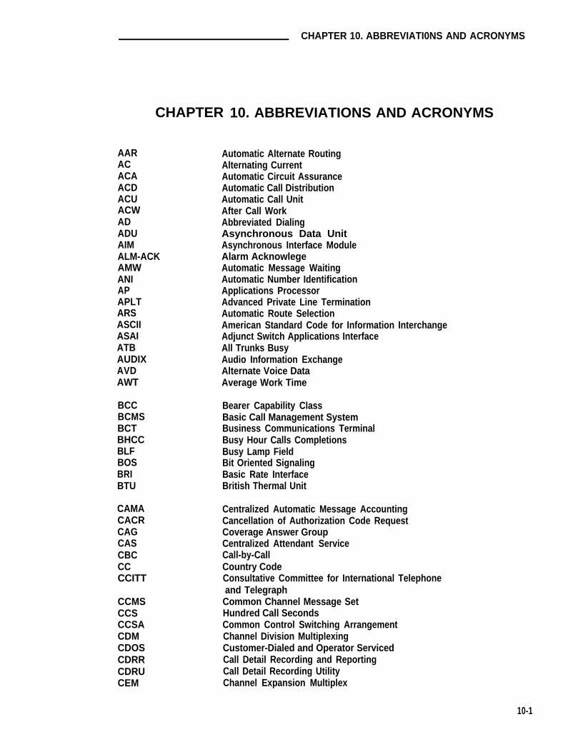
CHAPTER 10. ABBREVIATI0NS AND ACRONYMS
AARACACAACDACUACWADADUAIMALM-ACKAMWANIAPAPLTARSASCIIASAIATBAUDIXAVDAWT
BCCBCMSBCTBHCCBLFBOSBRIBTU
CAMACACRCAGCASCBCCCCCITT
CCMSCCSCCSACDMCDOSCDRRCDRUCEM
CHAPTER 10. ABBREVIATIONS AND ACRONYMS
Automatic Alternate RoutingAlternating CurrentAutomatic Circuit AssuranceAutomatic Call DistributionAutomatic Call UnitAfter Call WorkAbbreviated DialingAsynchronous Data UnitAsynchronous Interface ModuleAlarm AcknowlegeAutomatic Message WaitingAutomatic Number IdentificationApplications ProcessorAdvanced Private Line TerminationAutomatic Route SelectionAmerican Standard Code for Information InterchangeAdjunct Switch Applications InterfaceAll Trunks BusyAudio Information ExchangeAlternate Voice DataAverage Work Time
Bearer Capability ClassBasic Call Management SystemBusiness Communications TerminalBusy Hour Calls CompletionsBusy Lamp FieldBit Oriented SignalingBasic Rate InterfaceBritish Thermal Unit
Centralized Automatic Message AccountingCancellation of Authorization Code RequestCoverage Answer GroupCentralized Attendant ServiceCall-by-CallCountry CodeConsultative Committee for International Telephoneand TelegraphCommon Channel Message SetHundred Call SecondsCommon Control Switching ArrangementChannel Division MultiplexingCustomer-Dialed and Operator ServicedCall Detail Recording and ReportingCall Detail Recording UtilityChannel Expansion Multiplex
10-1

CHAPTER 10. ABBREVIATIONS AND ACRONYMS
CMDRCMSCOCORCOSCPCPECPTRCRCCSACSM
DCDCEDCPDCSDDCDDDDIDDLCDLDMDMIDNDDNISDODDOSSDS1DSUDTDMDTEDTGSDTMFDXS
E&MEBCDICEIEIAEMIEPNEPROMEPSCSESFETN
FACFASFCCFICFNPA
Centralized Message Detail RecorderCall Management SystemCentral OfficeClass of RestrictionClass of ServiceCircuit PackCustomer-Provided EquipmentCall Progress Tone ReceiverCyclical Redundancy CheckingCanadian Safety AssociationCentralized System Management
Direct CurrentData Communications EquipmentDigital Communications ProtocolDistributed Communications SystemDirect Department CallingDirect Distance DialedDirect Inward DialedData Line CircuitData Line Data ModuleDigital Multiplexed InterfaceDo Not DisturbDialed Number Identification ServiceDirect Outward DialedDelivery Operations Support SystemData Services Level 1Data Service UnitDigital Terminal Data ModuleData Terminal EquipmentDirect Trunk Group SelectDual Tone MultifrequencyDirect Extension Selection
Ear and Mouth (Receive and Transmit)Extended Binary Coded Decimal Interexchange CodeExpansion InterfaceElectronic Industries AssociatonElectro-Magnetic InterferenceExpansion Port NetworkErasable Programmable Read Only MemoryEnhanced Private Switched Communications ServicesExtended Superframe FormatElectronic Tandem Network
Feature Access CodeFacility Associated SignalingFederal Communications CommissionFacility Interface CodesForeign Numbering Plan Area
10-2
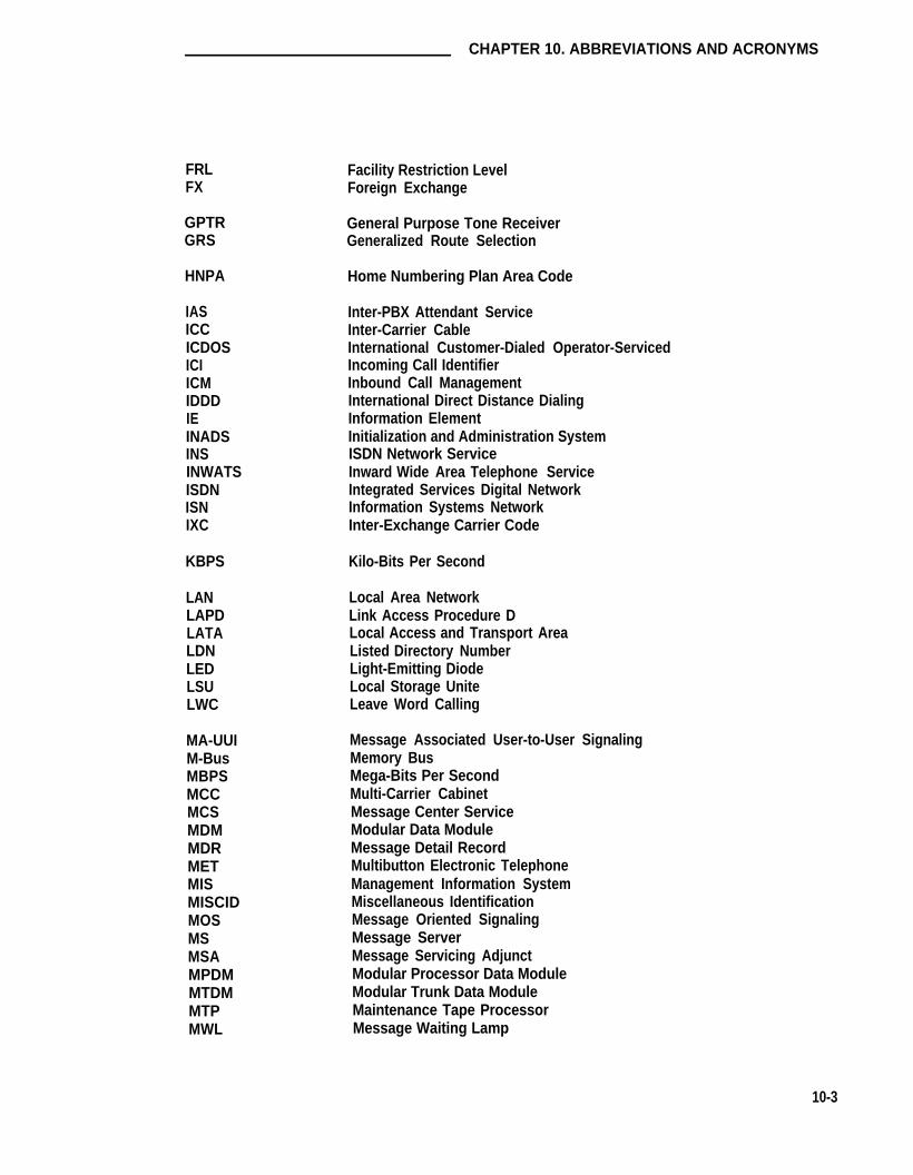
CHAPTER 10. ABBREVIATIONS AND ACRONYMS
FRLFX
GPTRGRS
HNPA
IASICCICDOSICIICMIDDDIEINADSINSINWATSISDNISNIXC
KBPS
LANLAPDLATALDNLEDLSULWC
MA-UUIM-BusMBPSMCCMCSMDMMDRMETMISMISCIDMOSMSMSAMPDMMTDMMTPMWL
Facility Restriction LevelForeign Exchange
General Purpose Tone ReceiverGeneralized Route Selection
Home Numbering Plan Area Code
Inter-PBX Attendant ServiceInter-Carrier CableInternational Customer-Dialed Operator-ServicedIncoming Call IdentifierInbound Call ManagementInternational Direct Distance DialingInformation ElementInitialization and Administration SystemISDN Network ServiceInward Wide Area Telephone ServiceIntegrated Services Digital NetworkInformation Systems NetworkInter-Exchange Carrier Code
Kilo-Bits Per Second
Local Area NetworkLink Access Procedure DLocal Access and Transport AreaListed Directory NumberLight-Emitting DiodeLocal Storage UniteLeave Word Calling
Message Associated User-to-User SignalingMemory BusMega-Bits Per SecondMulti-Carrier CabinetMessage Center ServiceModular Data ModuleMessage Detail RecordMultibutton Electronic TelephoneManagement Information SystemMiscellaneous IdentificationMessage Oriented SignalingMessage ServerMessage Servicing AdjunctModular Processor Data ModuleModular Trunk Data ModuleMaintenance Tape ProcessorMessage Waiting Lamp
10-3
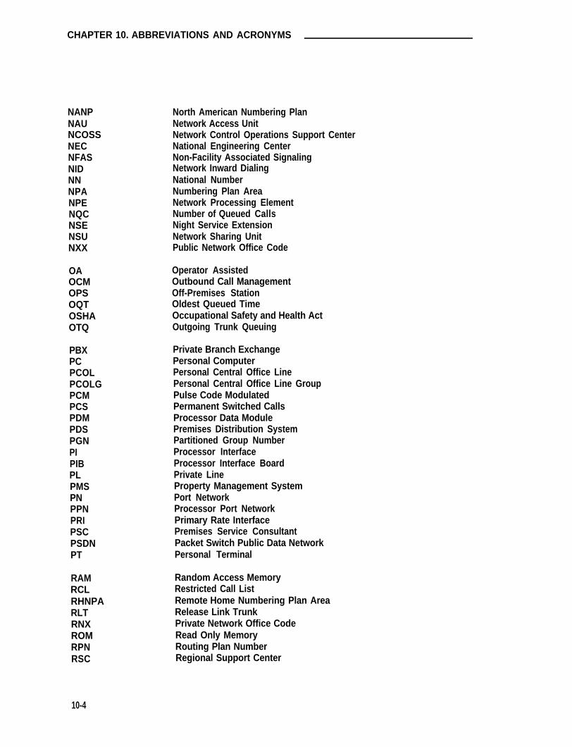
CHAPTER 10. ABBREVIATIONS AND ACRONYMS
NANPNAUNCOSSNECNFASNIDNNNPANPENQCNSENSUNXX
OAOCMOPSOQTOSHAOTQ
PBXPCPCOLPCOLGPCMPCSPDMPDSPGNPIPIBPLPMSPNPPNPRIPSCPSDNPT
RAMRCLRHNPARLTRNXROMRPNRSC
North American Numbering PlanNetwork Access UnitNetwork Control Operations Support CenterNational Engineering CenterNon-Facility Associated SignalingNetwork Inward DialingNational NumberNumbering Plan AreaNetwork Processing ElementNumber of Queued CallsNight Service ExtensionNetwork Sharing UnitPublic Network Office Code
Operator AssistedOutbound Call ManagementOff-Premises StationOldest Queued TimeOccupational Safety and Health ActOutgoing Trunk Queuing
Private Branch ExchangePersonal ComputerPersonal Central Office LinePersonal Central Office Line GroupPulse Code ModulatedPermanent Switched CallsProcessor Data ModulePremises Distribution SystemPartitioned Group NumberProcessor InterfaceProcessor Interface BoardPrivate LineProperty Management SystemPort NetworkProcessor Port NetworkPrimary Rate InterfacePremises Service ConsultantPacket Switch Public Data NetworkPersonal Terminal
Random Access MemoryRestricted Call ListRemote Home Numbering Plan AreaRelease Link TrunkPrivate Network Office CodeRead Only MemoryRouting Plan NumberRegional Support Center
10-4

CHAPTER 10. ABBREVIATIONS AND ACRONYMS
SAKISATSCCSCISCOSDNSDDNSIDSITSMDRSPESSISTARLANSXS
TAASTACTCMTDMTEGTODTOPTSCTTRTTTNTTY
UAPUCDUCLUDPUNPUPS
VDN
WATS
Sanity and Control InterfaceSystem Access TerminalSingle Carrier CabinetSwitch Communications InterfaceSystem Control OfficeSoftware Defined NetworkSoftware Defined Data NetworkStation Identification NumberSpecial Information TonesStation Message Detail RecordingSwitch Processing ElementStandard Serial InterfaceStar-based Local Area NetworkStep-by-Step
Trunk Answer From Any StationTrunk Access CodeTraveling Class MarkTrunk Data ModuleTerminating Extension GroupTime of DayTask Oriented ProtocolTechnical Service CenterTouch-Tone ReceiverTandem Tie Trunk NetworkTeletypewriter
Usage Allocation PlanUniform Call DistributionUnrestricted Call ListUniform Dial PlanUniform Numbering PlanUninterruptible Power Supply
Vector Directory Number
Wide Area Telecommunications Service
10-5

GLOSSARY
GLOSSARY
A
Access Code
A 1-, 2-, or 3-digit dial code used to activate or cancel a feature or access an outgoingtrunk. The star (*) and pound (#) can be used as the first digit of an access code.
Access Endpoint
Either a non-signaling channel on a DS1 interface or a non-signaling port on an AnalogTie Trunk circuit pack that is assigned a unique extension.
Access Tie Trunks
Tie trunks used to handle normal ETN calls between main and tandem switches.
ACD split
An ACD split is a UCD/DDC hunt group in a system where ACD has been optioned bythe customer and the hunt group has been administered as used for ACD. ACD Splitsare capable of being measured (data conceming the split and its members’ status will besent to the CMS).
Adjunct
Any processor connected to the switch and capable of controlling certain functionalities.
Adjunct-Controlled Split
An ACD split that is administered to be under adjunct control. Login to such a split isunder adjunct control. When an ACD agent is logged into an adjunct-controlled split, theACD agent’s voice set is locked.
Administer
To access and change the parameters associated with the services or features of thesystem.
Administered Connection
An end-to-end connection between two access endpoints or two data modules that isautomatically established whenever the system is restarted or the administered connec-tion is administered and the administered connection is due to be active.
Agent
An agent is a member of a hunt group. The term “ACD agent” is used to specify that thehunt group in question is an ACD split.
G-1

GLOSSARY
Announcements
Announcements are prerecorded messages that give the caller information. If the firstannouncement given to a caller is played before the call is queued to any split, it is aForced First Announcement.
Answer-Back Code
A code dialed to retrieve a parked call.
Answer Supervision
Answer supervision is a signal, sent from the switch to the serving CO, that tells the COto begin recording toll charges for a call. However, while a call waits in queue, AT&TACD software often delays sending answer supervision so that the ACD owner/operatoror caller can avoid excessive toll charges. Call vectoring commands work in a similarmanner; several steps behave differently depending on whether answer supervision hasbeen supplied. The call vectoring commands that most notably affect or depend uponanswer supervision are the announcement, busy, disconnect, and wait commands.
Appearance
See Call Appearance.
Applications Processor
A minicomputer used to support several user-controlled applications such as trafficanalysis and electronic documentation.
ARS/AAR Digit Conversion
ARS Digit Conversion replaces the initial digit of a number dialed after the ARS accesscode (or of a call crossed over from AAR) with another digit string. The call is thenmuted as if the modified digits were dialed after the AAR access code. AAR DigitConversion reptaces the initial digits of a number dialed after the AAR access code withanother digit string. The call is then routed as if the modified digits were dialed after theAAR access code.
ASAI Adjunct
Any adjunct that makes use of the ASAI (Adjunct/Switch Application Interface) protocol,including adjuncts that perform Inbound Call Management (ICM) functions.
Asynchronous Data Transmission
A scheme for transmitting data where each character is preceded by a start bit and fol-lowed by a stop bit, permitting data elements to occur at irregular intervals. This typetransmission is advantageous when transmission is not regular (characters typed at akeyboard).
G-2

GLOSSARY
Asynchronous Data Unit (ADU)
A data communications equipment (DCE)-type device that allows direct connectionbetween EIA-232-C equipment and the system digital switch.
Attendant
The operator of the attendant console. Individual who handles the processing of varioustypes of internal, incoming, and outgoing calls. May also manage and monitor some ofthe system’s operations.
Attendant Console
An electronic call-handling position with pushbutton control. Used by attendants toanswer and place calls and to manage and monitor some of the system operations.
Audio Information Exchange (AUDIX)
A unit that provides voice mail service to users.
Authorization Codes
Authorization Codes have three purposes. First, certain trunk groups that receive incom-ing calls can be administered to require authorization codes for incoming calls.Secondly, Remote Access to PBX Services users can be required to enter an authoriza-tion code instead of, or in addition to, a barrier code when accessing local PBX facilities.Lastly, they can be used for rerouting ARS/AAR calls that were blocked because thedefault FRL was not high enough to continue routing.
Auto-In
Auto-in is an ACD agent work mode that makes the agent available to receive calls andallows the agent to receive a new ACD call immediately after disconnecting from the pre-vious call.
Automatic Alternate Routing (AAR)
Used to route calls over altemate private and public network facilities in the order ofpreference specified by the customer. The preference order is specified by translating agroup of trunks into a routing pattern that is used for calls to a particular network location.AAR also provides privilege checking that allows the customer to restrict access to partic-ular trunk groups to a limited set of users. This is done by comparing the FRL of the cal-ling party with the FRL of the particular routing pattern entry.
Automatic Call Distribution
Termination of incoming calls to agents that have been administered into hunt groupscalled splits. Calls are distributed according to the algorithm selected by the customer,either UCD or Direct Department Calling (DDC).
G-3

GLOSSARY
Automatic Route Selection
Automatic Route Selection provides automatic routing of outgoing calls over customertrunk facilities with transparent access to an Inter-Exchange Carrier (IXC) based on theDirect Distance Dialing (DDD) number. Alternate trunk groups are selected during peakdemand periods when the primary trunk groups are busy. The alternate trunk groups areselected in decreasing order of preference for making the calls.
Automatic Route Selection Partitioning
ARS Partitioning provides for up to eight different user groups having access to their ownor shared trunk groups in ARS patterns.
Automatic Trunk
A trunk that does not require the sending or receiving of digits. The destination ispredetermined. A request for service on the trunk (called a seizure) is sufficient to routethe call. The normal destination of an automatic trunk is the system attendant group.
Automatic Restoration
A service that restores disrupted connections between access endpoints (non-signalingtrunks) and data endpoints (devices that connect the switch to dataterminal communications equipment). This restoration is achieved within seconds of aservice disruption so that critical data applicitions can remain operational.
Auxiliary Work
Auxiliary Work is an ACD agent work mode that makes the agent unavailable to receiveany ACD calls for the specified split. It is used when an agent is performing non-ACDrelated activities, such as going on a break
Available Agent
An ACD agent is considered available to receive a call through an ACD split if logged inand not on a tail, and in the Auto-In or Manual-In mode.
B
Barrier Code
A security code used with the Remote Access feature to prevent unauthorized access tothe system.
Basic Call Management System
The BCMS provides traffic reports for ACD. The reports area subset of the adjunct CMSapplications.
G-4

GLOSSARY
Bearer Capability Class (BCC)
The Bearer Capability Class (BCC) identifies the type of a call, for example, voice anddifferent types of data. Determination of BCC is based on the call originator’s charac-teristics for non-ISDN endpoints and on signaling in the D-channel for ISDN endpoints.There are five Bearer Capability Classes (0-4), based on voice and data Modes 0, 1, 2, 3capabilities.
Bit (Binary Digit)
One unit of information in binary notation (having two possible states or values, 0 or 1 ).
Bridge (Bridging)
The appearance of a voice terminal’s extension at one or more other voice terminals.
Bridged Appearance
A call appearance on a voice terminal that matches a call appearance on another voiceterminal for the duration of a call.
Buffer
A circuit or component that isolates one electrical circuit from another.holds data from one circuit or process until another circuit or processthe data.
Typically, a bufferis ready to accept
Bus
A multiconductor electrical path used to transfer information over a common connectionfrom any of several sources to any of several destinations.
Bus, Time Division Multiplex
See Time Division Multiplex Bus.
Business Communications Terminals
An advanced series of semi-intelligent terminals.
Bypass Tie Trunks
One-way, outgoing tie trunks from a tandem switch to a main switch in an ETN. Thesetrunks, provided in limited quantities, are used as a “last-choice” route when all trunks toanother tandem switch are busy. Bypass tie trunks are used only if all applicable inter-tandem trunks are busy.
Byte
A sequence of bits, 8 bits long, that is usually shorter than a word. A word is 16 bitslong.
G-5

GLOSSARY
C
Call Appearance, Attendant Console
Six buttons, labeled a through f, used to originate, receive, and hold calls. Each buttonhas two associated lamps to show the status of the call appearance.
Call Appearance, Voice Terminal
A button labeled with an extension number used to place outgoing calls, receive incomingcalls, or hold calls. Two lamps next to the button show the status of the call appearanceor status of the call.
Call Classification
The function of receiving and/or detecting call progress tones and call outcomes (ringing,busy, answered) and notifying the adjunct responsible for recording the call status. Callclassification may be done by the switch automatically or done by the user listening tocall progress tones.
Call Management System (CMS)
An adjunct processor that collects data from an ACD and generates reports to be storedor displayed concerning status of agents, splits, and trunks.
Callback Call
A call that is automatically returned to a voice terminal user who activated the AutomaticCallback or Ringback Queuing feature.
Call Vector
A set of up to 15 vector commands to be performed for an incoming or internal call.
Call Vectoring
A flexible call handling method of managing incoming calls that gives unique treatment toa particular call type based on dialed number or trunk terminating to a vector. Vectorcommands dictate the treatment given to callers.
Call Vector Step
Vectors are made up of 15 steps that are processed sequentially unless a “GoTo” vectorcommand is encountered or vector processing stops.
Call Waiting Ringback Tone
A low-pitched tone identical to the ringback tone except the tone decreases the last 0.2second. This tone notifies the attendant that the Attendant Call Waiting feature has beenactivated and that the called user is aware of the waiting call.
G-6

GLOSSARY
Call Work Code
A number, up to 16 digits, entered by ACD agents to record the occurrence of customer-defined events (such as account codes, social security numbers, or phone numbers) onACD calls.
Central Office
The location housing telephone switching equipment that provides local telephone ser-vice and access to toll facilities for long-distance calling.
Central Office Codes
The first three digits of a 7-digit public network telephone number. These codes are typi-cally numbered from 200 through 999.
Central Office Trunk
A telecommunications channel that provides access from the system to the public net-work through the local central office.
Channel
A communications path for transmitting voice and data.
Circuit Pack Vintage
The vintage of a circuit pack is a numeric tag to identify the Read Only Memory thatresides on that pack. It is used to facilitate recordkeeping and maintainability.
Class of Restriction (COR)
A number (0 through 63) that specifies the restrictions assigned to voice terminals, voiceterminal groups, data modules, and trunk groups.
Class of Service (COS)
A number (0 through 15) that specifies if voice terminal users can activate the AutomaticCallback, Call Forwarding-All Calls, Data Privacy, or Priority Calling features.
Common Control Switching Arrangement (CCSA)
A private telecommunications network using dedicated trunks and a shared switchingcenter for interconnecting company locations.
Confirmation Tone
Three short bursts of tone followed by silence; indicates that the feature activated, deac-tivated, or canceled has been accepted.
G-7

GLOSSARY
Console
See Attendant Console.
Controlled Outward Restriction
A calling party with this feature activated is restricted from dialing outgoing exchange net-work calls. Restricted calls are routed to the attendant, coverage, or intercept.
Controlled Restrictions
The controlled restrictions are distinct from the calling and called restrictions admin-istered through the COR. Controlled Restrictions are activated by an attendant or by astation with the “Console Permission” COS. The controlled restrictions are activated foran individual terminal or for a predefined group of terminals. The COR is used to pre-define a group of terminals.
Controlled Station-to-Station Restriction
A calling party or called party with this feature activated is restricted from placing orreceiving station-to-station calls. Restricted calls are muted to the attendant, coverage,or intercept.
Controlled Terminatlon Restriction
A called party with this feature activated is restricted from receiving any calls. Restrictedcalls are routed to the attendant, coverage, or intercept. This form of controlled restric-tion is used in the Do Not Disturb feature to prevent termination to a user. It may beoverridden only by a priority call.
Controlled Total Restriction
A calling party or called party with this feature activated is restricted from placing orreceiving any calls. DID or APLT calls to a station with Controlled Total Restriction activeare routed to the attendant or to a recorded announcement. All other calls are routed tointercept.
Coverage Answer Group
A group of up to eight voice terminals that ring simultaneously when a call is redirected toit by Call Coverage. Anyone of the group can answer the call.
Coverage Call
A call that is automatically redirected from the called party’s extension number to analternate answering position when certain coverage criteria are met.
Coverage Path
The order in which calls are redirected to alternate answering positions.
G-8

GLOSSARY
Coverage Point
The attendant positions (as a group), Direct Department Calling group, Uniform Call Dis-tribution group, Coverage Answer Group, a voice terminal extension, or Message CenterHunt Group designated as an alternate answering position in a coverage path.
Covering User
The person at an alternate answering position who answers a coverage call.
D
Data Channel
A communications path between two points used to transmit digital signals.
Data Communications Equipment (DCE)
The equipment on the network side of a communications link that provides all the func-tions required to make the binary serial data from the source or transmitter compatiblewith the communications channel.
Data Endpoint
Data endpoints refer to the various Data Terminal Equipment (DTE) and Data Communi-cations Equipment (DCE) that are connected to the system. They are associated with anextension. In the switching environment, they can be analog or digital endpoints servingas the interface between a host computer port and the switch, or between a data networkand the switch.
Data Terminal Equipment (DTE)
Equipment comprising the source or link of data, or both, that also provides communica-tion control functions (protocol). DTE is any piece of equipment at which a communica-tions path begins or ends.
D-Channel Pair
Refers to a pair of D-Channels, where one is designated as the primary D-Channel, andthe other is the secondary D-Channel.
Delay-Dial Trunk
G-9
After a request for service (called a seizure) is detected on an incoming trunk, the systemsends a momentary signal followed by a steady tone over the trunk. This informs the cal-ling party that dialing can start. This type of trunk allows dialing directly into the system.That is, the digits are received as they are dialed.

GLOSSARY
Designated Voice Terminal
The specific voice terminal to which calls, originally directed to a certain extensionnumber, are redirected. Commonly used to mean the “forwarded-to” terminal when CallForwarding All Calls is active.
Dialed Number Identification Service
Provides an indication (display) to the answering agent of the service (or project) ornumber called by the caller so that agents grouped in one split may answer callsappropriately for many different services.
Dial Repeating Tie Trunk
A telecommunications channel between two private switching systems. The numberdialed is repeated or dialed-in at the distant end.
Digital Communications Protocol (DCP)
Defines the capability for providing simultaneous voice and data transmission over thesame channel.
Digital Data Endpoints
Digital data endpoints include the following:
● 510D Personal Terminal or 513 Business Communications Terminal
● 7404D Terminals
● 7406D or 7407D Equipped With Optional Data Module Base
● Asynchronous Data Units
● Digital Terminal Data Modules
● (Modular) Processor Data Modules
● (Modular) Trunk Data Modules
● 3270 Data Modules
● Internal Data Channels
Digital Multiplexed Interface (DMI)
Specifies the remote interface requirements for multiplexed data communicationsbetween a host computer and a private switching system.
Digital Terminal Data Module (DTDM)
An adjunct to 7403D or 7405D voice terminals. Provides the required interface betweenthe system and a data terminal such as a 513 BCT.
G-10

GLOSSARY
Digital Trunk
A circuit in a telecommunications channel designed to handle digital voice and data.
Digit Conversion
A process used to convert specific dialed numbers into other dialed numbers. ARS usesDigit Conversion to convert public network numbers (ARS) to private network numbers(AAR) in order to save toll charges. AAR uses Digit Conversion to convert private net-work numbers (ARS) to other private or public network numbers (AAR).
Direct-Agent Calls
A special type of ACD call directed to a particular agent, rather than any available agentin the split.
Direct Agent Calling (DAC)
An entry is provided in the COR to allow originating and receiving of direct-agent calls. Adirect-agent call is a special type of ACD call directed to a particular agent, rather thanany available agent in the split. A calling party that is DAC restricted is denied the abilityto originate direct-agent calls. A called party that is DAC restricted is denied the ability toreceive direct-agent calls. Restricted calls are muted to intercept.
Direct Extension Solution (DXS)
An option at the attendant console that allows an attendant direct access to voice termi-nals by pressing a Group Select button and a DXS button.
Distributed Communications System (DCS)
The Distributed Communications System is a private network of distributed switcheslinked together with trunks to form a DCS complex. The switches in the complex areconnected with data links that allow call processing information to be passed from oneswitch to another. This provides feature transparency so that certain features are per-ceived by users to be the same whether they are talking to a station served by the sameswitch or to a station on a different switch in the complex.
DS1
A DS1 trunk multiplexes up to 24 64-kbps digital channels over a 4-wire interface for dataor voice. The 64-kbps capacity is achieved by having 8000 frames of 8-bit data persecond. This trunk can be used as a timing reference for the switch or by an externalStratum 3 clock.
G-11

GLOSSARY
E
Electronic Tandem Network (ETN)
A special tandem tie trunk network that has automatic call routing capabilities based onthe number dialed and most preferred route available at the time the call is placed. Eachswitch in the network is assigned a unique RNX and each voice terminal is assigned aunique extension number.
End-to-End Signaling
The transmission of touch-tone signals generated by dialing from a voice terminal user toremote computer equipment. A connection must first be established over an outgoingtrunk from the calling party to the computer equipment. Then additional digits can bedialed to transmit information to be processed by the computer equipment.
Enhanced Private Switched Communications Service (EPSCS)
A private telecommunications network that provides advanced voice and data telecom-munications services to companies with many locations.
Expansion Interface
Used to connect an EPN to the Processor Port Network TDM Bus and provide connec-tivity between the TDM buses on the PPN and EPNs. This circuit pack carries synchroni-zation information between the two cabinets that it connects and also provides connec-tivity between the packet buses on the PPN and EPNs.
Expansion Port Network
A cabinet that contains port circuit packs but no processor. Up to two EPNs may be con-nected to a PPN.
Extension Number
A 1- to 5-digit number assigned to each voice terminal, certain system groups, datamodules, and various other facilities on the switch. The number is used in call process-ing to access the facility.
External Call
A connection between a system user and a party on the public telephone network or on atie trunk.
G-12

GLOSSARY
F
Facility
A general term used for the telecommunications transmission pathway and associatedequipment.
Facility Restriction Level (FRL)
The FRL is used to determine the accessibility of user trunk groups in a routing pattern.When searching for a routing pattern, the originator's FRL must be greater than or equalto the FRL for the accessed trunk group.
FAS/NFAS
Facility Associated Signaling (FAS) describes the type of signaling in which an ISDN DS1interface D-Channel carries signaling information for only those B-Channels located onthe same DS1 facility as the D-Channel. Non-Facility Associated Signaling describes thetype of signaiing in which an ISDN DS1 interface D-Channel carries signaling informationon one DS1 facility for B-Channels located on another DS1 facility.
Feature
A specificity defined function or service provided by the system.
Feature Button
A labeled button on a voice terminal or attendant console designating a specific feature.
Foreign Exchange (FX)
A central office other than the one providing local access to the public telephone network.
Foreign Exchange Trunk
A telecommunications channel that directly connects the system to a central office otherthan its local central office.
Foreign Numbering Plan Area Code
An area code other than the local area code. The foreign area code must be dialed tocall outside the local geographical area.
G-13

GLOSSARY
G
Ground-Start Trunk
On outgoing calls, the system transmits a request for services to the distant switchingsystem by grounding the trunk ring lead. When the distant system is ready to receive thedigits of the called number, that system grounds the trunk tip lead. When the systemdetects this ground, the digits are sent. (Tip and ring are common nomenclature to dif-ferentiate between ground-start trunk leads.) On incoming calls, detection of ground onthe ring lead is sufficient to cause the call to route to a predetermined destination, nor-mally the system attendant group. No digits are received.
H
Handshaking Logic
A format used to initiate a data connectbn between two data module devices.
Home Numbering Plan Area Code
The local area code. The area code does not have to be dialed to call numbers withinthe local geographical area.
Hospitality
Hospitality features, such as Automatic Wakeup and Do Not Disturb, are those requiredfor the administration of stations considered to be “guests” or “clients” of the customer.Additionally, these features allow the customer to mnnect the system to a PMS, which isused to collect and manage guest room information.
Hospitality Parameter Reduction
Provides the user with a reduced set of system parameters. Namely, the number oftrunks, number of hunt-groups, number of pick-up groups, and the number of coveragepaths.
Host
A customer processor that, when connected to the switch using ASAI, for example, isconsidered an adjunct.
Hunt Group
A group of stations which answer calls that are distributed using a routing algorithm. AnACD split is a special type of hunt group.
G-14

GLOSSARY
I
Immediate-Start Tie Trunk
After establishing a connection with the distant switching system for an outgoing call, thesystem waits a nominal 65 milliseconds before sending the digits of the called number.This allows time for the distant system to prepare to receive the digits. Similarly, on anincoming call, the system has less than 65 milliseconds to prepare to receive the digits.
Information Exchange
The exchange of data between users of twohost computer) over a local area network
Initialization and Administration System (INADS)
different systems (DEFINITY Generic 1 and
An AT&T Network Operations Division (NOD) services alarm reception and trouble track-ing system.
Integrated Services Digital Network—Primary Rate Interface (ISDN-PRI)
ISDN-PRI is an internationally accepted standard interface that provides end-to-end digi-tal connectivity. It uses a high-speed interface which provides service-independentaccess to switches services. It uses a T1 interface and supports 23 64-kbps voice ordata B-Channels and one 64-kbps signaling D-channel (on the 24th channel when usingFAS) or 24 B-Channels on one DS1 facility and a D-Channel on a separate DS1 facility(when using Non-facility Associated Signaling) for a total bandwidth of 144 MB.
Intercept Tone
An alternatingrequested.
Interface
high and low tone; indicates a dialing error or denial of the service
A common boundary between two systems or pieces of equipment.
Interflow
Interflow allows calls directed or redirected to one split to be redirected to an externaldestination.
Internal Call
A connection between two users within the system.
G-15

GLOSSARY
Interworking
The linking of dissimilar networks to provide an end-to-end call. In public networks, inter-working might include a Common Channel Interoffice Signaling (CCIS) path which doesnot support ISDN. In private networks, a tandeming PBX might interface an existing ana-log facility to an ISDN facility to provide calls end-to-end.
Intraflow
Intraflow allows calls that are unanswered within a predefined time, at a split to beredirected to other splits on the same switch.
In-Use Lamp
A red lamp on a multi-appearance voice terminal that lights to show which call appear-ance will be selected when the handset is lifted or which call appearance is active when auser is off-hook
Inward Restriction
A called party that is inward restricted is denied the ability to receive incoming exchangenetwork calls, attendant originated calls, and attendant completed calls. A call that isdenied because of termination or inward restriction is routed to intercept, the attendant,or a recorded announcement depending on the calling party. If the calling party is a DID,Advanced Private Line Termination (APLT), or tie trunk the call is routed to the attendantor recorded announcement, at the customer's option. In all other cases the call is routedto intercept.
ISDN-Basic Rate Interface (ISDN-BRI)
ISDN-BRI is one of the two standard ISDN frame formats. The ISDN-BRI is typicallyused to connect telephones or work stations to an ISDN-capable switching system. Itprovides one 16-kbps signaling and data channel (D-channel) and two 64-kbps informa-tion channels (B-channels). The primary purpose of the signaling channel is to conveyQ.931 message-oriented signaling for the setup and tear down of calls carried by the B-Channels on the BRI interface.
For G1V5.0 system, ISDN-BRI is only used to provide an ASAI link to the switch in sup-port of the Inbound Call Management feature.
ISDN Gateway
G-16
An adjunct network that forwards information from the switch to a host for data screendelivery to agents in an ACD split.

GLOSSARY
L
Link
A transmitter-receiver channel or system that connects two locations.
Listed Directory Number
A LDN is a publicly listed telephone number for an organization. These numbers areadministered as special extensions, each associated with a 15-character name. DID forany of these extensions causes routing of the call to the attendant group with the ter-minating attendant display indicating an LDN call and the name associated with thedialed extension.
Local Clock
The tone/clock circuit pack that has a local oscillator that can be used to maintain timingfor the switch if DS1s are not used or if both DS1 primary and secondary clock refer-ences fail.
Lookahead Interflow
Lookahead Interflow is an enhancement to Call Vectoring that checks the status ofremote ACD locations that calls may be interflowed to. For example, calls under vectorcontrol will not interflow to a remote ACD location that is not accepting calls. This capa-bility will be provided via the use of a private or public network ISDN-PRI connection withthe receiving switch having the capability to reject or accept the call.
Loop-Start Trunk
After establishing a connection with the distant switching system for an outgoing call, thesystem waits for a signal on the loop formed by the trunk leads before sending the digitsof the called number. On incoming calls, the received request for service is sufficient tocause the call to route to a predetermined destination, normally the system attendantgroup. No digits are received.
M
Main/Satellite/Tributary
A Main switch provides: interconnection, via tie trunks, with one or more subtendingswitches, called Satellites; all attendant positions for the Main/Satellite configuration; and,access to and from the public network. To a user outside the complex, a Main/Satelliteconfiguration appears as a single switch, with a single LDN. A Tributary is a switch, con-nected to the Main via tie trunks, but which has its own attendant position(s) and its ownLDN.
G-17

GLOSSARY
Manual-In
Manual-In is an ACD agent work mode that makes the agent available to receive callsand automatically puts the agent into After Call Work mode after disconnecting from anACD call.
Manual Terminating Line Service
A called party that has manual terminating line service is only allowed to receive calls ori-ginated or extended by an attendant. Termination of all other calls is denied.
Message Center
An answering service for calls that might otherwise go unanswered; an agent acceptsand stores messages for later retrieval.
Message Center Agent
A member of the Message Center Hunt Group who takes andvoice terminal users.
Miscellaneous Station Restriction
A calling party can be disallowed access to preselected groups
retrieves messages for
of terminals. The termmiscellaneous refers to this grouping of terminals. Any or all terminals can be in a givenmiscellaneous station restriction group. This restriction is controlled by the CORsassigned to the calling party and to the terminal being accessed. All terminals in a givenmiscellaneous station restriction group must be assigned the same COR. A calling partyis restricted by its COR which denies permission to call the terminal’s COR. Restrictedcalls are routed to intercept.
Miscellaneous Trunk Restriction
A calling party can be disallowed access to preselected groups of trunk groups. Theterm miscellaneous refers to this preselected grouping of trunk groups. Any or all trunkgroups can be in a given miscellaneous trunk restriction group. This restriction is con-trolled by the CORs assigned to the calling party and to the trunk group being accessed.All trunk groups in a given miscellaneous trunk restriction group must be assigned thesame COR. A calling party is restricted by its COR which denies permission to call thetrunk group’s COR. Restricted calls are routed to intercept.
Modular Processor Data Module (MPDM)
See Processor Data Module.
Modular Trunk Data Module (MTDM)
See Trunk Data Module.
G-18

GLOSSARY
Modem Pooling
Provides shared-use conversion resources that eliminate the need for a dedicatedmodem when a data module accesses, or is accessed by, an analog line or trunk.
Multi-Appearance Voice Terminal
A terminal equipped with several call appearance buttons for the same extensionnumber. Allows the user to handle more than one call, on that same extension number,at the same time.
Multiplexer
A device for simultaneous transmission of two or more signals over a common transmis-sion medium.
N
Network
An arrangement of inter- and/or intra-location circuits designed to perform specific func-tions.
Non-Facility Associated Signaling
See FAS/NFAS.
O
Offhook
Term used for the switchhook up, or the Speakerphone turned on, or the Headsetplugged in. For multi-appearance stations, the term offhook also includes choosing a callappearance on which to originate the call.
Off-Net
Off-Net facilities (for example, WATS, FX, or CO trunk groups) are not part of acustomer's private network but may be utilized to carry private network calls. Wheneverthe call uses Off-Net facilities, it is called an Off-Net call.
Onhook
Term used for a depressed switchhook, the Speakerphone turned off, or the Headsetunplugged. Also, depression of the Disconnect button sends an onhook message, fol-lowed by an offhook message.
G-19

GLOSSARY
On-Net
On-Net facilities (for example, TTI trunks, private ISDN-PRI trunks) are dedicated to acustomer's private network. Whenever the call is routed over the customer's privatetrunking facilities, it is called an On-Net call.
Outward Restriction
A calling party that is outward restricted is denied the ability of directly accessing theexchange network ●
P
Paging Trunk
A telecommunication channel used to access an amplifier for loudspeaker paging:
Partitioned Group Numbar (PGN)
A Partitioned Group Number (PGN) is a number (1-8) assigned to different groups ofusers. The PGN is used to determine the AAR/ARS services to be provided on a call. APGN is not used directly to restrict the user, it is only used as a method toindicate thechoice of call routing tables (AAR/ARS Analysis forms) to be used to process a call.
Pickup Group
A group of individuals authorized to answer any call directed to an extension numberwithin the group.
Port
A designation of the location of a circuit that provides an interface between the systemand lines and/or trunks.
Port Network
May be either an EPN or a PPN.
Primary Rofaronce
A DS1 circuit pack facility used as a reference for clock timing synchronization; the pri-mary reference should be chosen to be a more reliable DS1 link.
G-20

GLOSSARY
Primary/Secondary D-Channel
The D-Channel Backup feature requires that one D-Channel be administered as the pri-mary D-Channel, and that a second D-Channel be administered as the secondary D-Channel. The reason for this distinction is that at certain times during the D-ChannelBackup procedures, both D-Channels are in the same state, and it is imperative in orderto avoid a deadlock situation that both switches at opposite ends of the PRI select thesame D-Channel to be put into service. In these case, the primary D-Channel is givenprecedence over the secondary D-Channel.
Principal (User)
In terms of Call Coverage, a person for whom a call was originally intended.
Priority Queuing
An entry is provided in the COR to allow priority queuing. The queuing priority of a callcan be raised such that when a call with increased priority is queued, it is queued aheadof calls of normal priority. This priority queuing is for non-vector controlled calls andnon-direct-agent calls.
Private Networking
A Private Network is a network of customer switches linked with private lines that carryvoice and data communication throughout the network. A Private Network is character-ized by a uniform numbering plan that includes the assignment of a unique number toeach station in the network The Automatic Alternate Routing (AAR) Analysis table isused to route private network calls.
Private Network Office Code (RNX)
The first three digits of a 7-digit private network number. These codes are numbered 220through 999, excluding any codes that have a 0 or 1 as the second digit.
Privileged Station
A station that has been administered with console privileges allowing it to perform func-tions normally associated with an attendant.
Processor Data Module (PDM)
Provides the required interface between the system and an Electronics Industries Associ-ation (EIA) computer or data terminal.
Processor Port Network (PPN)
The cabinet in which the switch processor resides. Only one of these per switch isallowed.
G-21

GLOSSARY
Property Management System (PMS)
A stand-alone computer that lodging and health services organizations use for servicessuch as reservations, housekeeping, billing, etc.
Protocol
A set of conventions or rules governing the format and timing of message exchanges tocontrol data movement and correction of errors.
Public Network
The network that can be openly accessed by all customers for local or longdistance cal-ling.
Q
Queue
An ordered sequence of calls waiting to be processed.
Queuing
The process of holding calls in order of their arrival to await connection to an attendant,to an answering group, or to an idle trunk.
R
Random Access Memory (RAM)
A storage arrangement whereby information can be retrieved at a speed independent ofthe location of the stored information.
Read Only Memory (ROM)
A storage arrangement primarily for information retrieval applications.
Recall Dial Tone
Three short bursts of tone followed by steady dial tone; it indicates that the system hascompleted some action (such as holding a call) and is ready to accept dialing.
Redirectlon Criteria
The information administered for each voice terminal’s coverage path that determineswhen an incoming call is redirected to coverage.
G-22

GLOSSARY
Remote Access Barrier Code
Used with remote access trunks to limit access to the System. When a call comes in ona remote access trunk, the user may be required to dial a barrier code to gain access. Ifthe user dials an invalid barrier code, the call is muted to intercept. A barrier code hasan associated COR that defines call restriction features and a COS that defines featurerestrictions. The use of barrier codes is a customer option. If barrier codes are used,they apply to all remote access trunk groups in a given system. If they are not required,the default barrier code’s COR is used. There may be more than one barrier code in thesystem.
Remote Home Numbering Plan Area Code (RHNPA)
A foreign numbering plan area code that is treated as a home area code by the ARSfeature. Calls can be allowed or denied based on the area code and the dialed centraloffice code rather than just the area code. If the call is allowed, the ARS pattern used forthe call is determined by these six digits.
Removable Mass Storage Subsystem (RMSS)
A tape storage device that stores the software information for the system.
Reorder Tone
A fast-busy tone repeated 120 times a minute; indicates that at least one of the facilities,such as a trunk or a digit transmitter, required for the call was not available at the timethe call was placed.
Restricted Call List
A list of digit strings that can be assigned to any COR.
Routing Pattern
A routing pattern is a list of up to six trunk groups that ARS and AAR use to try to selecta trunk when muting outgoing calls. There are a maximum of 254 routing patterns thatcan be assigned. The patterns can be shared between the AAR and ARS features.Trunk groups are arranged in the routing pattern in descending order of desirability (mostdesirable first). If the first choice route (usually the least expensive facility) is unavail-able, a call is attempted over the second choice route. This procedure continues until anavailable route is found, or all muting preferences are exhausted.
G-23

GLOSSARY
sSecondary Reference
The secondary reference is a backup DS1 facility used as a clock timing reference forsynchronization in case the primary reference fails or has too many slips.
Service Observing
Service observing allows users to monitor calls. Once the feature is activated and a sta-tion call is being monitored, the activating user has the capability to toggle back and forthbetween a listen-only connection and a listen/talk connection on the call. Subsequentcalls at the station can be monitored without having to reactivate the feature.
Signaling Groups
Refers to a group of B-Channels for which a given D-Channel (or D-Channel Pair) willcarry the signaling information.
Single-Line Voice Terminals
Voice terminals served by a single-line tip and ring circuit (for example, Models 500,2500, 7101A, and 7103A).
Software
A set of computer programs that accomplish one or more tasks.
Special Information Tones (SIT)
Tones that precede certain recorded announcements provided by the network. Suchannouncements are used when the caller encounters a condition that requires an expla-nation (for example, “no such number’).
Split
A condition whereby a caller is temporarily separated fromdant. This split condition automatically occurs when thepresses the Start button.
Status Lamp
a connection with the atten-attendant, active on a call,
A green lamp that shows the status of a call appearance or a feature button by the stateof the lamp (lighted, flashing, fluttering, broken flutter, or dark).
Stratum 3 Clock
This is the most accurate clock supported by the system; it is duplicated and has a hold-over of 24 hours. The implementation requires external hardware to provide timing to theTN780 Tone/Clock circuit pack.
G-24

GLOSSARY
Stroke Counts
Method used by ACD agents to record up to nine customer-defined events on a per callbasis when the CMS is active.
Suffix
A suffix is an alphabetic character (for example, A, B, or C) that is sometimes appendedto a circuit pack code (TN number). It indicates additional feature functionality of a partic-ular circuit pack.
Switchhook
The button(s) on a voice terminal located under the receiver.
Switch Processing Elemont (SPE)
The complex of circuit packs that provide high level processing functions within theswitch.
Synchronous Data Transmission
A scheme for sending and receiving data, where data elements may occur only at regularspecified times. Sending and receiving devices must operate in step with each other.
System Manager
A person responsible for specifying and administering features and services for the sys-tem.
System Reload
A process that allows stored data to be written from a tape into the system memory(normally after a power outage).
T
Tandem Switch
A switch within an ETN that provides the logic to determine the best route for a networkcall, possibly modifies the digits outpulsed, and allows or denies certain calls to certainusers.
Tandem Through
The switched connection of an incoming trunk to an outgoing trunk without human inter-vention.
G-25

GLOSSARY
Tandem Tie Trunk Network (TTTN)
A private network that interconnects several customer switching systems by dial-repeating tie trunks. Access to the various systems is dictated by codes that must beindividually dialed for each system.
Terminal Alarm Notification
A method of customer alarm notification using lamps associated with feature buttons onmulti-appearance digital or hybrid voice terminals or attendant console terminals or both.
Termination Restriction
A called party that is termination restricted is denied the ability to receive any calls at anytime.
Third Party Call Control
ASAI capabilities that allow a host/adjunct to take control of a call, to transfer theetc.
call,
Tie Trunk
A telecommunications channel that directly connects two private switching systems.
Time Division Multiplex Bus
A special bus that is time shared by preallocating short time slots to each transmitter ona regular basis. In a PBX, all port circuits are connected to the time division multiplexbus permitting any port to send a signal to any other port.
Time Division Multiplexed (TDM)
A switching technique of spliting a large bandwidth into many small channels (called timeslots) in the time domain.
Time of Day Routing (TOD)
Time of Day Routing allows the routing of calls economically, based on time of day andday of week. The customer has the option of changing the routing plan up to six timeseach day for each day of the week. The choice of routing plan is made from a pool ofrouting plans. These routing plans are used in conjunction with the routing of ARS andAAR calls.
Toll Restriction
A calling party that is toll restricted cannot make calls to certain numbers defined on theToll List unless the number is contained on a UCL defined on the Toll Analysis form andassociated with the calling party’s COR.
G-26

GLOSSARY
Tone/Clock
The Tone/Clock circuit pack provides tone generation and timing for the TDM bus. Theactive Tone/Clock circuit pack is currently providing service for the cabinet in a duplicatedsystem whereas the standby tone/clock is a backup circuit pack in the event the activetone/clock fails.
Tone Ringer
A device with a speaker, used in electronic voice terminals to alert the user.
Trunk
A telecommunications channel between two switching systems.
Trunk Data Module
Provides the required interface between the system and a data set (modern) or data ser-vice unit connected to a private or switched data line.
Trunk Group
Telecommunications channels assigned as a group for certain trunking functions.
U
Uniform Dial Plan (UDP)
A feature that allows a unique 4- or 5-digit number assignment for each terminal in amulti-switch configuration, such as a DCS or Main/Satellite/Tributary configuration.
Unrestricted Call List
A list of digit strings that can be accessed by a user.
V
Vector Controlled Split
A hunt group or ACD split is vector controlled when the field “Vector” is enabled on theHunt Group form. Only vector-controlled hunt groups or vector-controlled ACD splits areaccessible via the vector commands “queue to main” and “check backup”.
Vector Directory Number (VDN)
A number that can be dialed to access a vector. Several VDNs may map into the samevector.
G-27

GLOSSARY
Vectoring (Basic)
Allows the customer to specify the treatment of calls coming into the switch based uponthe dialed number. Vectoring (Basic) allows incoming calls to be placed in a queue for ahunt group or split and may specify the delay treatment given to the caller.
Vectoring (Prompting)
Allows a call vector to collect digits from a user and use that information in routing thecall.
Voice Terminal
A single-line or multi-appearance voice terminal (telephone).
W
Wide Area Telecommunications Service (WATS)
A service that allows calls to a certain area or areas for a flat-rate charge based onexpected usage.
Wink-Start Tie Trunk
After establishing a connection with a distant switching system for an outgoing call, thesystem waits for a momentary signal (wink) before setting the digits of the callednumber. Similarly, on an incoming call, the system sends the wink signal when ready toreceive digits.
Write Operation
The process of putting information onto a storage medium such as magnetic tape.
Z
Zip Tone
Single burst tone is provided with auto-answering operation when an agent answers anACD call.
G-28

INDEX
INDEX
4410 Terminal, 2-1Administration Keys, 2-15Function Keys, 2-15Keyboard, 2-1
4425 Terminal, 2-1Administration Keys, 2-15Function Keys, 2-15Keyboard, 2-1
513 BCT, 2-1Keyboard, 2-1, 2-4Keyboard, Function Keys
and Programmable Keys, 2-10Programmable Function Keys, 2-11
610 BCT, 2-1Administration Keys, 2-15Function Keys, 2-15Keyboard, 2-1
615 MT Terminal, 2-1Administration Keys, 2-15Function Keys, 2-15Keyboard, 2-1
715 MT Terminal, 2-3keyboard overview, 2-3
7400B Data Module, 5-9
A
Access Codes, 3-2Access System, 4-1Add Feature Buttons to Voice Terminal, 5-4Add Features to Voice Terminal, 5-4Add Netcon Channels, 4-6Add Voice Terminal, 5-3Administer
Abbreviated Dialing, 3-4Call Coverage Answer Groups, 3-4Circuit Packs, 6-1
Groups, 3-4Hunt Groups, 3-4Intercom Groups, 3-4Netcon Channels, 4-6Pickup Groups, 3-4System, 3-1System From Remote Location, 4-6Terminating Extension Groups, 3-4Trunk Groups, 3-4Voice Terminals, 5-1
Administration Circuit Pack, 6-2Administration Terminal, 2-1
Types, 2-1Administration Without Hardware, 5-8Administrative Tasks
System 4-1Voice Terminal, 5-1
Announcement Data Module, 5-9Announcement
error conditions, 8-7restore, 7-1, 8-5save, 8-2
Assign Netcon Channels, 4-6for Off-Premises Administration/Maintenance
Terminals, 4-6for On-Premises Administration/Maintenance
Terminals, 4-6for SMDR, 4-6
Assign New Password, 4-3Assigning
Add Station Command to513 Function Key, 2-11
Administration Functions to513 Function Key, 2-11
Change Station Command to513 Function Key, 2-11
Circuit Packs, 6-1Circuit Packs to Slots, 6-1Programmable Function Keys, 2-11
Data Module and Voice Terminal Adjuncts, 5-9 Programmable Function Keys, 513 BCT, 2-11Dial Plan, 4-8 Attendant Console, 3-2Feature Access Codes, 4-8 Parameters, 3-2
I-1

INDEX
B
Backspace Key, 2-4Backup, 7-1
for a System With Duplication Option, 7-4for a System Without Duplication
Option Tape, 7-2Backup Disk, 8-1Backup Disk/Tape, 8-1Backup Recorded Announcements, 7-1Backup System, 7-1, 8-1Backup Tape
for a System Without Duplication Option, 7-2Business Communications Terminal
513, 2-1513, Keyboard, 2-1610, 2-1610, Keyboard, 2-1
C
Cancel Key, 2-1Cassette Tapes, 7-2, 7-4
Errors, 7-6Failures, 7-6
ChangeDate, 4-10Day of Week, 4-10Dial Plan Record, 4-8Feature Access Codes, 4-8Hour, 4-10Minutes, 4-10Month, 4-10Netcon Channel, 4-8Password, 4-4Password Screen Form, 4-3Time, 4-10Time for Daylight Savings Time, 4-10Voice Terminal, 5-4Voice Terminal, Button Assignments, 54Voice Terminal, Features, 5-4Voice Terminal, Translation, 5-4Year, 4-10
Choosing a Terminal, 4-1
Circuit PackAdministration, 6-1, 6-2Assignments, 6-1configurations, 6-1
Class of Restriction, 3-2Class of service, 3-2Clear Field Key, 2-1Commands
History, 4-13To Change Netcon Channel, 4-8To List Netcon Channel, 4-8To List System Configurations, 6-1Used to Administer Netcon Channels, 4-6Used to Backup Recorded
Announcements, 7-1Used to Save Recorded Announcements, 7-1Voice Terminal, 5-3
Configuration Control, 6-1Console Parameters, 3-2Cursor Keys, 2-4
513 BCT, 2-4
D
Data Line Data Module, 5-9Data Modules, 3-3
7400B Data Module, 5-9Administration, 5-9Announcement, 5-9Data Line, 5-9Digital Terminal Data Module, 5-9Modular Processor Data Module, 5-9Modular Trunk Data Module, 5-9Processor, 5-9Trunk Data Module, 5-9
Data Modules Administer, 5-9Date and Time Screen Form, 4-10Daylight Savings Time, 4-10Delete Voice Terminal, 5-4
From System Translations, 5-4Dial Plan, 3-2
Establish, 3-2Establish Data Modules, 3-3Digital Terminal Data Module
Administration, 5-9
I-2

INDEX
DisplayInformation Voice Terminal, 5-5Translation Data Associated
With Voice Terminal, 5-5
E
Enhanced Terminal Administration, 5-1Enter Key, 2-1Error Conditions, 8-2, 8-17Establish Dial Plan, 3-2
F
Feature Access Codes, 3-2Features
Administration Without Hardware, 5-8Find
Extension Numbers Assignedto Netcon Channels, 4-8
How Many Netcon ChannelsHave Been Assigned, 4-8
Function Keys, 2-4513 BCT, 2-4Assignments, by System Software, 2-1Assignments, for 4410, 2-1Assignments, for 4425, 2-1Assignments, for 610 BCT, 2-1Assignments, for 615 MT, 2-1Assignments, for PC 6300, 2-1
G
Glossary, G-1
H
Hardware RequirementsModules, 5-10Voice Terminal Adjuncts, 5-10
Help Key, 2-1History Command, 4-13How to Administer
Circuit Packs, 6-1How to Assign
Circuit Packs, 6-1Circuit Packs, to Slots, 6-1
How to BackupRecorded Announcements, 7-1
How to ChangeDate, 4-10Your Password, 4-3
How to ConfigureCircuit Packs, 6-1
How to ListConfiguration Commands, 6-1
How to Log In, 4-1Version 1 System, 4-1Version 2 System, 4-1Version 3 System, 4-1
How to Logoffthe System, 4-3
How to Printa Screen Form, 4-13
How to RestoreAnnouncements, 7-1
How to SaveRecorded Announcements, 7-1
How to SetTime, 4-10Time and Date, 4-10
How to UseCancel Key, 2-1Clear Field Key, 2-1Enter Key, 2-1Help Key, 2-1Next Form Key, 2-1Next Page Key, 2-1Previous Page Key, 2-1Refresh Key, 2-1
I-3

INDEX
I
Identify Groupsto Which a Voice Terminal Belongs, 5-5
Incorrect Login, 4-2Initialization, 1-2Initialize System, 1-2Introduction, 1-1
K
Keeping Records, 1-2Keyboard Overview
715 MT, 2-3
N
Netcon Channels, 3-3, 4-5Administration, 4-6and SMDR, 4-6
Network Access Feature Forms, 3-4Next Form Key, 2-1Next Page Key, 2-1
O
Ongoing Administration, 1-2
P
L
Label Backup Tapesfor a System With Duplication Option, 7-4for a System Without Duplication Option, 7-2
ListConfiguration Commands, 5-1Netcon Channels, 4-3
Login, 3-2, 4-1Procedures System, 4-1
Logoff, 4-1Command, 4-3the System, 4-3
Logs Transaction, 4-13
M
Module Administration, 5-9Modules, 3-3
Digital Data, 3-3Processor Data, 3-3Trunk Data, 3-3
ParametersAttendant Console, 3-2System, 3-3
Password Change, 4-3PC 6300 Terminal, 2-1Perform Tape Backup
for a System With Duplication Option, 7-4for a System Without Duplication Option, 7-2
Previous Page Key, 2-1Print Command, 4-13
With Display Command, 5-5Print Data Associated With Voice Terminal, 5-5Print Information for Voice Terminal, 5-5Print on Demand, 4-13Print Screen Form 4-13
on Terminal Printer, 4-13Processor Data Modules, 3-3
Administration, 5-9Programmable Function Keys
for a 513 BCT, 2-11How to Set up, 2-11
Programmable Keys, 2-4513 BCT, 2-4for a 513 BCT, 2-11
I-4

INDEX
R
Record Keeping, 1-2Recorded Announcements
Backup, 7-1command, 7-1
References, 9-1Refresh Key, 2-1Remote Administration, 44Remove and Replace Tapes
for System Backup, for a SystemWith Duplication Option, 7-4
for System Backup, for a SystemWithout Duplication Option, 7-2
Remove Feature ButtonsFrom Voice Terminal, 5-4
Remove Features From Voice Terminal, 5-4Remove Voice Terminal, 5-4Reset Clock After System Recovery, 4-10Reset Date, 4-10Reset System Clock, 4-10Reset Time, 4-10Restore Announcements, 8-5
command, 8-5command denial, 8-5command operation, 8-5options, 8-5
Restore Recorded Announcements, 7-1
S
Save Announcements, 7-1, 8-2command, 8-2command denial, 8-3command operation, 8-3options, 8-2
Save ChangesAdditions, 7-1
Save Data in Memory, 7-1Save Information in Memory, 7-1Save Recorded Announcements, 7-1
Command, 7-1
Save Translation, 7-1Automatically, 7-1Command, 7-1, 8-9in Memory, 7-1When to, 7-1
SequenceUsed to Administer System, 3-1Used to Enter System Translations, 3-1
Set Date, 4-10Set Time, 4-10Set-Up Netcon Channels, 4-6Set Up Program Function Keys
513 BCT, 2-11Set Up System for Remote Administration, 4-4SMDR and Netcon Channels, 4-6Station Configurations, 6-1System
Access, 4-1Administration, 1-2, 3-1Backup, 7-1, 8-1Features, 3-2Implementation, 1-1Initialization, 1-2Login Procedures, 4-1Logoff Procedure, 4-3Maintenance, 1-1Parameters, 3-3Reconfiguration, 6-1Remote Administration, 4-4
System Administrative Tasks, 4-1System Function Key Assignments
for 4410, 2-1for 4425, 2-1for 610 BCT, 2-1for 615 MT, 2-1
T
Table Terminal Keys, 2-5Tape Backup
for a System With Duplication Option, 7-4for a System Without Duplication Option, 7-2
Tape Errors, 7-6Tape Failures, 7-6
I-5

INDEX
Terminal615 MT Terminal, 2-1Keyboard, 615 MT Terminal, 2-1Keys Table, 2-5
Terminal Types, 2-1Used for Administration, 2-1
Time and Date Screen Form, 4-10Time Required
to do a Backup onRecorded Announcements, 7-1
Transaction Log, 4-13Trunk Configurations, 6-1Trunk Data Module Administration, 5-9Trunk Data Modules, 3-3Trunk Groups, 3-4Types of Administration Terminals, 2-1
I-6
v
Voice Terminal, 3-3Add, 5-3Adjuncts Administer, 5-9Administer, 5-1Change, 5-4commands, 5-3Remove, 5-4
w
When toSave Recorded Announcements, 7-1Use Manual, 1-3

DEFINITY®
System Management
AT&T 555-230-500ADDIssue 1, January 1992Dated September 1992
Communications SystemGeneric 1 and Generic 3
Addendum

©1992 AT&TAll Rights ReservedPrinted in USA
NoticeWhile reasonable effort was made to ensure that the information in this document was complete and accurate atthe time of printing, AT&T cannot assume responsibility for any errors. Changes and/or corrections to theinformation contained in this document may be incorporated into future issues.
Your Responsibility for Your System’s Security
You are responsible for the security of your system. AT&T does not warrant that this product is immune fromor will prevent unauthorized use of common-carrier telecommunication services or facilities accessed throughor connected to it. AT&T will not be responsible for any charges that result from such unauthorized use.Product administration to prevent unauthorized use is your responsibility and your system administrator shouldread all documents provided with this product to fully understand the features available that may reduce yourrisk of incurring charges.
Federal Communications Commission (FCC) statement
This equipment generates, uses, and can radiate radio-frequency energy and if not installed and used inaccordance with the instruction manual, may cause interference to radio communications. It has been testedand found to comply with the limits for a Class A computing device pursuant to Subpart J of Part 15 of FCCRules, which are designed to provide reasonable protection against such interference when operated in acommercial environment
Operation of this equipment in a residential area is likely to cause interference, in which case the user at his/herown expense will be required to take whatever measures may be required to correct the interference.
TRADEMARK NOTICE
DEFINITY is a registered trademark of AT&T.
ORDERING INFORMATION
Call: AT&T Customer Information Center1 800 432-6600In Canada: 1 800 255-1242
Write: AT&T Customer Information Center2855 North Franklin RoadP.O. Box 19901Indianapolis, Indiana 46219-1385
Order: Document No. 555-230-500ADDIssue 1, September 1992
Published byBCSystems Product Documentation Development GroupAT&T Bell LaboratoriesMiddletown, NJ

Contents
INTRODUCTIONOverview
............................................................................................................. 1
............................................................................................................... 1
Organization .................................................................................................................... 2
SYSTEM BACKUP FOR DEFINITY G3s ............................................................................ 1-1
Save Translation ..................................................................................................... 1-1
Save and Restore Recorded Announcements ........................................................ 1-1
Backup for a G3s System ...................................................................................................... 1-1
Errors ............................................................................................................................ 1-4
Index ................................................................................................................ I-1
i

Figures
Figure 1-1. Save Translation—SPEA ................................................................................................ 1-2
Figure 1-2. Save Announcements Screen—SPEA ................................................................. 1-3
Figure 1-3. Memory Card Write-Protect Switch .......................................................................... 1-5
ii

INTRODUCTION
INTRODUCTION
Overview
This addendum provides specific information for performing a System Backup for a DEFINITY®Communications System Generic 3s (G3s) switch release. Its function is as a supplement to, andis intended to be used in conjunction with, the information already provided in DEFINITY Com-munications System Generic 1 and Genetic 3 System Management, 555-230-500, Issue 1.
For additional information on DEFINITY Generic 3s, refer to DEFINITY Generic 3s FeatureDescription, 555-230-201ADD2, and DEFINITY Communications System Generic 3s SystemDescription, 555-230-200ADD.
1

INTRODUCTION
Organization
Note: In the interest of brevity, only G3s specific information is provided in this addendum.Refer to the appropriate section in DEFINITY Communications System Generic 1and Generic 3 System Management, 555-230-500, Issue 1, when performing otheradministration tasks.
This document consists of the following chapters:
Introduction — Describes this document.
System Backup for DEFINITY G3s – Describes the tasks involved in backing up the DEFINITYG3s system, including translations, saving and restoring recorded announcements, memory cardbackup, and memory card errors.
2

SYSTEM BACKUP FOR DEFINITY G3s
SYSTEM BACKUP FOR DEFINITY G3s
The backup system for the DEFINITY G3s system employs a Memory Card. It does not have aduplication option. In case of a power failure, the system translations andbe restored using the Memory Card.
Save Translation
announcements can
Translation data can be routinely saved every 24 hours. However, if your translation datachanges frequently, you should also save translations frequently to assure that you have themost up-to-date information. You should also alternate the Memory Cards.
Warnings: “save translation” should not be performed if any Memory Card alarm condi-tions occur or if the system is having problems.
It is recommended that “save translation” be performed after business hours sodial tone delays will not be encountered.
Save and Restore Recorded Announcements
Enter the save announcements command to save the recorded announcements in the systemon the system Memory Cards.
Note: A 4 Mb Memory Card is required to save and restore announcements.
The system takes about 30 minutes to complete this task. Because the administration terminal isunavailable during this time, it is recommended that this command be used after business hours.During this time period, the administration terminal cannot be used to administer the system untilthe transfer is complete; however, all other administration terminals, if provided, are allowed toperform administration procedures.
Enter the restore announcements command to restore the recorded announcements from theMemory Card back into system memory. The system takes about 22 minutes to complete thistask. The system performs an audit to make sure that the number of announcements onthe announcement board match the announcements administered in the switch.
The working copy of the announcements are stored on the announcement board. You shouldalso make a backup copy on a 4 Mb Memory Card.
Backup for a G3s System
One Memory Card is provided with the system. It is recommended that you purchase additionalcards. It is recommended that backup copies of the translation data be made weekly, orafter many changes have been made to the translation data. This will minimize the loss of recenttranslation data changes if the Memory Card in the system becomes damaged.
1-1

SYSTEM BACKUP FOR DEFINITY G3s
The following procedure can be used to make a backup Memory Card:
1. Remove the Memory Card from the Netcon circuit pack.
2. Insert the backup Memory Card into the Netcon circuit pack.
3. Login to the administration terminal.
4. Verify that the screen displays:
enter command:
5. Enter save translation and press [RETURN]. This command instructs the system totake all translation information in memory and transfer it into the Memory Card.
6. The screen displays:
save translation SPE ASAVE TRANSLATION
Processor Command Completion Status Error Code
SPE_A Success 0
Command successfully completelyenter command:
FIGURE 1-1. Save Translation—SPEA
7. Verify that the Success message appears in the Command Completion Status field.If it does not, an error message will appear instead.
8. If the system is equipped with a TN750 Announcement circuit pack, the recordedannouncements can be saved using the save announcements commands. Enter saveannouncements and press [RETURN].
1-2

SYSTEM BACKUP FOR DEFINITY G3S
9. The screen displays:
save announcementsSAVE ANNOUNCEMENTS
Processor Command Completion Status Error Code
SPE_A Success 0
Command successfully completelyenter command:
FIGURE 1-2. Save Announcements Screen—SPEA
10. Verify that the Success message appears in the Command Completion Status field.If it does not, an error message will appear instead.
11. Remove the backup Memory Card from the slot in which it is installed and insert the origi-nal Memory Card into that slot.
12. Label the backup Memory Card with the date and time it was updated. A special notationmay be put on the card to clearly distinguish it from other Memory Cards.
13. Store the backup Memory Card in a secure place.
1-3

SYSTEM BACKUP FOR DEFINITY G3s
Errors
Memory Card-related failures may occur for two reasons: the card is at fault or the Netcon circuitpack is at fault. When these failures occur, the system responds with “error messages.” The fol-lowing is a list of the error messages and recommended responses to each. Check for properoperation after each response is done.
1.
2.
3.
4.
5.
6.
7.
8.
Saved copy of announcements is unusable
The file on the Memory Card is unusable.
Response: Use another backup card if you have one. Instances such as this illustratethe importance of having backup cards.
Cannot access file storage area
The wrong Memory Card may be installed.
Response: Check to see which Memory Card is installed. If the correct one is installed,test it. If it passes, and the problem still persists, escalate the problem to the next levelof support.
Cannot turn on 12 volt power supply
Indicates something maybe wrong with the Netcon circuit pack (where the power supplyis).
Response: Test the 12-volt power supply by running the test card-mem command fromthe system adminstration terminal. Executing the command causes the system to runTest 701 (12 Volt Power Supply Test). If the power supply test fails, replace the Netconcircuit pack. To do this, follow the instructions in the Maintenance manual for MO 12v-PWR. Then, repeat whichever command failed.
Invalid directory on memory card
Indicates the Memory Card needs refreshing.
Response: Run test card-mem and be sure all tests pass.
Memory Card is unusable
Indicates something is wrong with the Memory Card.
Response: Replace the Memory Card.
Could not write to Memory Card.
Indicates something maybe wrong with the Memory Card.
Response: Test the Memory Card (run test card-mem.)
Cannot access mass storage system now; try again later
lndicates the storage system is in use.
Response: Try again later.
Request is incompatible with currently running operations
Indicates the storage system is in use.
Response: Try again later.
1-4

SYSTEM BACKUP FOR DEFINITY G3s
9.
10.
11.
12.
13.
14.
Memory Card is not inserted in the system
Response: Insert the Memory Card.
Cannot access file; wrong type of Memory Card is inserted
You have not inserted the correct Memory Card for the operation you wish to perform.Load the appropriate Memory Card.
File size exceeded
You have run out of file space.
Response: Call your AT&T representative.
Upgrade Memory Card inserted
You may have inserted the System Upgrade Memory Card instead of the 4 Mb Memorycard.
Response: Insert the 4 Mb Memory Card.
Memory Card is write-protected
Indicates the switch on the top side of the Memory Card is incorrectly set.
Response: Move the switch to the correct position with the point of a pencil or similarobject. Refer to the figure below:
FIGURE 1-3. Memory Card Write-Protect Switch
Transmission problem; please try later
There is a problem communicating with the announcement board.
Response: Check to see that the announcement board has been correctly administered.Use the change data <extension_number> command. Verify that the announcementboard is in the correct slot in the processor. It the location of the announcement board iscorrect, use the display data <extension_number of netcon data modules> to verify thatthe data modules are allowed to originate calls to the announcement board. Use displaydata <extension_number of the announcement data module> to verify that the datamodule on the announcement board is allowed to terminate calls from the netcon datamodules. Note that the netcon data modules must also be allowed to call each other. Ifall is correct, wait and retry.
1-5

SYSTEM BACKUP FOR DEFINITY G3S
15. Command has been aborted; please try later
The command has been pre-empted.
Response: Try again later.
16. Saved copy of translation is unusable
The copy of the translations on your Memory Card is faulty.
Response: Run the save translations command again.
17. Unknown type of Memory Card
The software does not know what type of Memory Card is inserted in the slot. This canoccur if the card is unformatted or if the current vintage of the software does not recog-nize that type of Memory Card.
Response: Replace the Memory Card with a formatted Memory Card that the softwarecan recognize.
1-6

Index
Index
M
A Memory Card Failures, 14Memory Cards, 1-1
Errors, 1-4Announcements Failures, 14
restore, 1-1
PB
Backup, 1-1for a G3s System, 1-1G3s System, 1-1using Memory Cards, 1-1
Backup Memory Card(s)for a G3s System, 1-1
Backup Recorded Announcements, 1-1Backup System, 1-1
C
Perform Backupfor a G3s System, 1-1
R
Recorded AnnouncementsBackup, 1-1command, 1-1
Remove and Replace Memory Cardsfor G3s System Backup, 1-1
Restore Recorded Announcements, 1-1
commandsUsed to Backup Recorded Announcements, 1-1 SUsed to Save Recorded Announcements, 1-1
E
Error messages, 1-4Errors, 1-4
H
How to BackupRecorded Announcements, 1-1
How to RestoreAnnouncements, 1-1
How to SaveRecorded Announcements, 1-1
Save Announcements, 1-1Save Changes,
Additions, 1-1Save Data in Memory, 1-1Save Information in Memory, 1-1Save Recorded Announcements, 1-1
Command, 1-1Save Translation, 1-1
Automatically, 1-1command, 1-1in Memory, 1-1When to, 1-1
System,Backup, 1-1
I-1

Index
T
Time Requiredto do a Backup on RecordedAnnouncements, 1-1
W
When toSave Recorded Announcements, 1-1
I-2

AT&T 555-230-500ADD2Issue 1, January 1992Dated March 1993
DEFINITY® Communications SystemGeneric 1 and Generic 3
System Management Addendum(G3vs Customers Only)

©1993 AT&TAll Rights ReservedPrinted in USA
NoticeWhile reasonable effort was made to ensure that the information in this document wascomplete and accurate at the time of printing, AT&T cannot assume responsibility for anyerrors. Changes and/or corrections to the information contained in this document maybeincorporated into future issues.
Your Responsibility for Your System’s Security
You are responsible for the security of your system. AT&T does not warrant that this productis immune from or will prevent unauthorized use of common-carrier telecommunicationservices or facilities accessed through or connected to it. AT&T will not be responsible for anycharges that result from such unauthorized use. Product administration to preventunauthorized use is your responsibility and your system administrator should read alldocuments provided with this product to fully understand the features available that mayreduce your risk of incurring charges.
Federal Communications Commission (FCC) Statement
This equipment generates, uses, and can radiate radio-frequency energy and, if not installedand used in accordance with the instruction manual, may cause interference to radiocommunications. It has been tested and found to comply with the limits for a Class Acomputing device pursuant to Subpart J of Part 15 of FCC Rules, which are designed toprovide reasonable protection against such interference when operated in a commercialenvironment.
Operation of this equipment in a residential area is likely to cause interference, in which casethe user at his/her own expense will be required to take whatever measures maybe requiredto correct the interference.
TRADEMARK NOTICE
DEFINITY is a registered trademark of AT&T.
ORDERING INFORMATION
Call:
Write:
Order:
AT&T Customer Information Center1 800 432-6600In Canada: 1 800 255-1242
AT&T Customer Information Center2855 North Franklin RoadP.O. Box 19901Indianapolis, IN 46219-1385
Document No. AT&T 555-230-500ADD2Issue 1, January 1992Dated March 1993
Published byGBCSystems Product Documentation Development GroupAT&T Bell LaboratoriesMiddletown, NJ 07748-0076

Contents
About this Document i■ Overview i■ Organization ii
1 SYSTEM BACKUP FOR DEFINITY G3VS 1-1■ Save Translation 1-1■ Save and Restore Recorded Announcements 1-5■ Errors 1-6
I Index I-1
i

Screens
1 SYSTEM BACKUP FOR DEFINITY G3VS
1-1. Save Translation Screen-SPEA 1-21-2. Save Announcements Screen-SPEA 1-21-3. Save Translation Screen-SPEA 1-31-4. Save Announcements Screen-SPEA 1-4
ii

About this Document
Overview
This addendum provides specific information for performing a System Backup fora DEFINITY® Communications System Generic 3vs (G3vs) switch release. Itsfunction is as a supplement to, and is intended to be used in conjunction with, theinformation already provided in DEFINITY Communications System Generic 1and Generic 3 System Management, 555-230-500, Issue 1.
For additional information on DEFINITY Generic 3vs, refer to DEFINITY Generic3VS Feature Description, 555-230-201ADD4, and DEFINITY CommunicationsSystem Generic 3vs System Description, 555-230-200ADD2.
i

About this Document
Organization
In the interest of brevity, only G3VS specific information is provided in thisaddendum. Refer to the appropriate section in DEFINITY CommunicationsSystem Generic 1 and Generic 3 System Management, 555-230-500,Issue 1, when performing other administration tasks.
This document consists of the following chapters:
Introduction — Describes this document.
System Backup for DEFINITY G3VS — Describes the tasks involved in backingup the DEFINITY G3VS system, including translations, saving and restoringrecorded announcements, memory card backup, and memory card errors.
ii

SYSTEM BACKUP FORDEFINITY G3VS 1
The backup system for the DEFINITY G3VS system employs a Memory Card.The standard Memory Card is a 1 Mb card for systems without a TN750announcement circuit pack. It does not have high or critical reliability. In case ofa power failure, the system translations and announcements can be restoredusing the Memory Card.
Save Translation
Translation data can be automatically saved every 24 hours. However, if yourtranslation data changes frequently, you should also save translations frequentlyto assure that you have the most up-to-date information.
Warnings:“Save transition” should not be performed if any Memory Card alarmconditions occur or if the system is having problems (such as processor,memory, or netcon alarms).
It is recommended that you save translation after business hours toprevent dial tone delays. Or, if your business operates 24 hours, youshould save translation during slow business hours.
The following procedure is used to save transitions to the Memory Card:
1. Verify that the Memory Card is in the TN777B Netcon circuit pack.
2. Log into the administration terminal.
3. Verify that the screen displays:
enter command:
1-1

SYSTEM BACKUP FOR DEFINITY G3vs
4. Enter save translation and press [RETURN]. This command instructsthe system to take all translation information in memory and transfer it intothe Memory Card.
5. The screen displays:
Error Code
0
save translation SPE ASAVE TRANSLATION
Processor Command Completion Status
SPE_A Success
Command successfully completelyenter command:
Screen 1-1. Save Translation Screen—SPEA
6. Verify that the Success message appears in the Command CompletionStatus field. If it does not, an error message will appear instead.
7. If the system is equipped with a TN750 Announcement circuit pack, therecorded announcements can be saved using the save announcementscommands. Enter save announcements and press [RETURN].
8. The screen displays:
save announcementsSAVE
Processor Command
ANNOUNCEMENTS
Completion Status
Success
Error Code
0SPE_A
Command successfully completelyenter command:
Screen 1-2. Save Announcements Screen—SPEA
9. Verify that the Success message appears in the Command CompletionStatus field. If it does not, an error message will appear instead.
1-2

SYSTEM BACKUP FOR DEFINITY G3vs
One Memory Card is provided with the system. If a backup Memory Card hasbeen purchased, the following procedure can be used to make a backup copy ofthe system translations and/or announcements.
1.
2.
3.
4.
5.
6.
Remove the Memory Card from the TN777B Netcon circuit pack.
Insert the backup Memory Card into the TN777B Netcon circuit pack.
Log in to the administration terminal.
Verify that the screen displays:
enter command:
Enter save translation and press [RETURN]. This command instructsthe system to take all translation information in memory and transfer it intothe Memory Card.
The screen displays:
save translation SPE_ASAVE TRANSLATION
Proccessor Command Completion Status Error Code
SPE_A Success 0
Command successfully completelyenter command:
Screen 1-3. Save Translation Screen-SPEA
7. Verify that the Success message appears in the Command CompletionStatus field. If it does not, an error message will appear instead.
8. If the system is equipped with a TN750 Announcement circuit pack, therecorded announcements can be saved using the save announcementscommands. Enter save announcements and press [RETURN].
1-3

SYSTEM BACKUP FOR DEFINITY G3vs
9. The screen displays:
save announcements
SAVE ANNOUNCEMENTS
Processor Command Completion Status Error Code
SPE_A Success 0
Command successfully completelyenter command:
Screen 1-4. Save Announcements Screen-SPEA
10.
11.
12.
13.
Verify that the Success message appears in the Command CompletionStatus field. If it does not, an error message will appear instead.
Remove the backup Memory Card from the slot in which it is installed andinsert the original Memory Card into that slot.
Label the backup Memory Card with the date and time it was updated. Aspecial notation may be put on the card to clearly distinguish it from otherMemory Cards.
Store the backup Memory Card in a secure place.
1-4

SYSTEM BACKUP FOR DEFINITY G3vs
Save and Restore RecordedAnnouncements
Enter the save announcements command to save the recorded announcementsin the system on the system Memory Cards.
NOTE:A 4 Mb Memory Card is required to save and restore announcements.
The system takes about 30 minutes to complete this task. Because theadministration terminal is unavailable during this time, it is recommended thatthis command be used after business hours (or during slow business hours for a24 hour business operation). During this time period, the administration terminalcannot be used to administer the system until the transfer is complete; however,all other administration terminals, if provided, are allowed to performadministration procedures.
Enter the restore announcements command to restore the recordedannouncements from the Memory Card back into system memory. The systemtakes about 22 minutes to complete this task. The system performs an auditto make sure that the number of announcements on the announcementboard match the announcements administered in the switch.
The working copy of the announcements are stored on the announcement board.You should also save announcements on 4 Mb Memory Cards.
1-5

SYSTEM BACKUP FOR DEFINITY G3vs
Errors
Memory Card-related failures may occur for two reasons: the card is at fault orthe (TN777B) Netcon circuit pack is at fault. When these failures occur, thesystem responds with “error messages.” The following is a list of the errormessages in alphabetical order and recommended responses to each. Check forproper operation after each response is done. You should also check thehardware error log for errors, and then use the maintenance manual or completerepair procedures.
1.
2.
3.
4.
5.
6.
Cannot access file storage area
The wrong Memory Card may be installed.
Response: Check to see which Memory Card is installed. If the correctone IS installed. test it. If it passes, and the problem still persists, escalatethe problem to the next level of support.
Cannot access file; wrong type of Memory Card is inserted
You have not inserted the correct Memory Card for the operation you wishto perform. Response: Load the appropriate Memory Card.
Cannot access mass storage system now; try again later
Indicates the storage system is in use.
Response: Try again later.
Cannot turn on 12 volt power supply
Indicates something may be wrong with the (TN777B) Netcon circuit pack(where the power supply is).
Response: Test the 12-volt power supply by running the test card-memcommand from the system administration terminal. Executing thecommand causes the system to run Test 701 (12 Volt Power SupplyTest). If the power supply test fails, replace the (TN777B) Netcon circuitpack. To do this, follow the instructions in the Maintenance manual forMO 12v-PWR. Then, repeat whichever command failed.
Command has been aborted; please try later
The command has been preempted.
Response: Try again later.
Could not write to Memory Card.
Indicates something may be wrong with the Memory Card.
Response: Test the Memory Card (run test card-mem).
1-6

SYSTEM BACKUP FOR DEFINITY G3vs
7.
8.
9.
10.
File size exceeded
You have run out of file space.
Response: Call your AT&T representative.
Invalid directory on memory card
Indicates the Memory Card needs refreshing, or that something is wrongwith the Memory Card.
Response: Run test card-mem and be sure all tests pass. Replace theMemory Card.
Memory Card is not inserted in the system
You have not inserted the memory card.
Response: Insert the Memory Card.
Memory Card is write-protected
Indicates the switch on the top side of the Memory Card is incorrectly set.
Response: Move the switch to the correct position with the point of apencil or similar object. Refer to the figure below:
Figure 1-1. Memory Card Write-Protect Switch
11. Memory Card is unusable
Indicates something is wrong with the Memory Card.
Response: Replace the Memory Card.
1-7

SYSTEM BACKUP FOR DEFINITY G3vs
12.
13.
14.
15.
Request is incompatible with currently running operations
Indicates the storage system is in use.
Response: Try again later.
Saved copy of announcements is unusable
The file on the Memory Card is unusable.
Response: Use another backup card if you have one. Instances such asthis illustrate the importance of having backup cards.
Saved copy of translations is unusable
The copy of the translations on your Memory Card is faulty.
Response: Run the save translations command again.
Transmission problem; please try later
There IS a problem communicating with the announcement board.
Response: Check to see that a data module, “Type: announcement” hasbeen administered correctly. Use the list data-module command todetermine if the data-module “Type: announcement” is administered. Thedata module “Type: announcement” is administered using the add data-module <extension_number of data module type announcement>. Ifadding or checking the data module type announcement, verify that the“Board:" field is translated with network, carrier and slot where theannouncement circuit pack is installed. Check that the Class ofRestriction (COR) of the data module “Type announcement” is allowed toterminate calls from the data-modules “Type: netcon.” The data modules“Type Netcon:” with their COR can be identified by using the “list data-module” command. Note the netcon data modules must also have theirCOR’s translated that they can call each other.
1-8

SYSTEM BACKUP FOR DEFINITY G3vs
16.
17.
Unknown type of Memory Card
The software does not know what type of Memory Card is inserted in theslot. This can occur if the card is unformatted or if the current vintage ofthe software does not recognize that type of Memory Card.
Response: Replace the Memory Card with a formatted Memory Card thesoftware can recognize.
Upgrade Memory Card inserted
You may have inserted the System Upgrade Memory Card instead of the4 Mb Memory Card.
Response: Insert the 4 Mb Memory Card.
1-9

Index
A
Announcementsrestore, 1-5
B
Backup, 1-1G3VS System, 1-1
using Memory Cards, 1-1Backup Recorded Announcements, 1-5Backup System, 1-1
C
CommandsBackup Recorded Announcements, 1-5Save Recorded Announcements, 1-5
E
Error messages, 1-6Errors, 1-6
M
R
Recorded AnnouncementsBackup, 1-5Command, 1-5
Restore Recorded Announcements, 1-5
S
Save Announcements, 1-5Save Changes
Additions, 1-1Save Data in Memory, 1-1
Save Information in Memory, 1-1Save Recorded Announcements, 1-5
Command, 1-5Save Translation, 1-1
Automatically, 1-1Command, 1-1in Memory, 1-1When to, 1-1
SystemBackup, 1-1
T
Time RequiredBackup on Recorded Announcements, 1-5
Memory Card Failures, 1-6Memory Cards, 1-1
Errors, 1-6Failures, 1-6
IN-1