deflaagr tion flame arrestersliterature.puertoricosupplier.com/075/wi74634.pdf60 d-˙ˆ˝ f- a- -...
TRANSCRIPT
57
Deflagration Flame Arresters
DeflaGraTiON flame arresTers
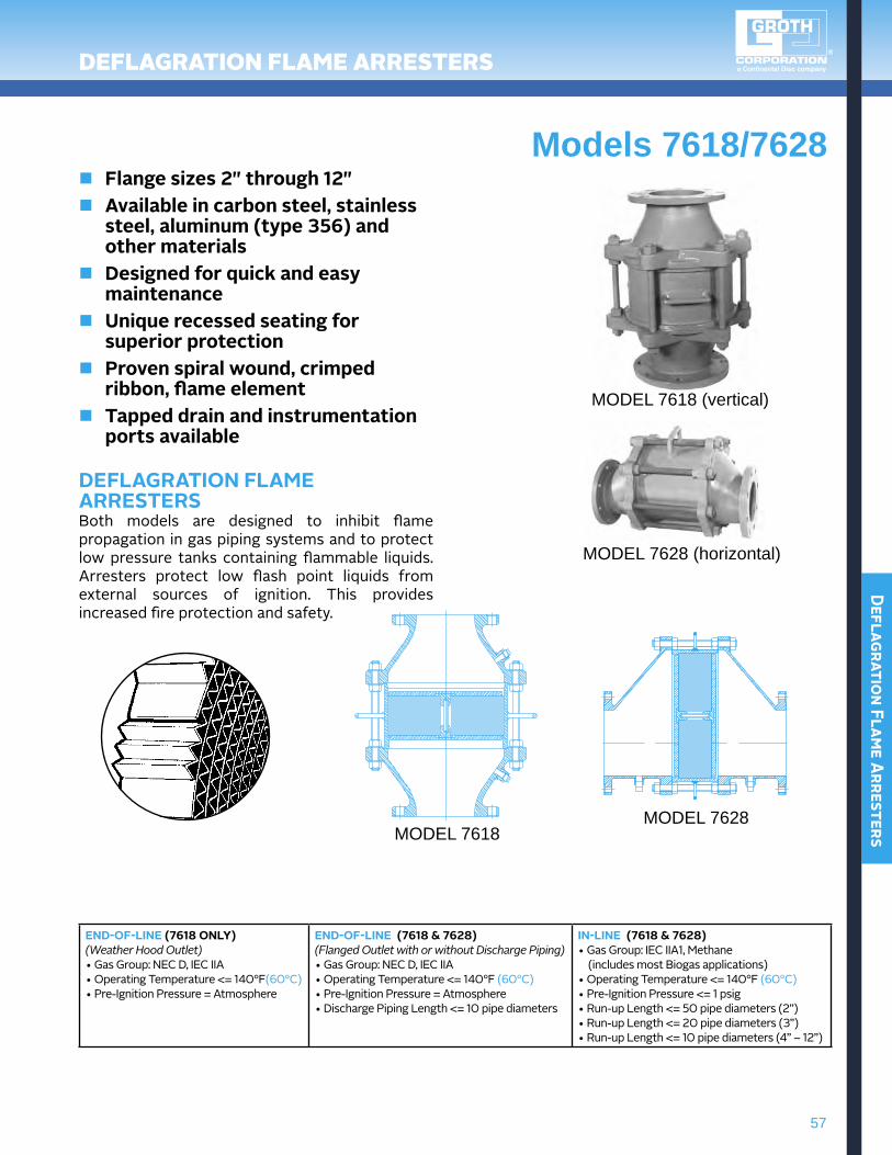
Models 7618/7628n Flange sizes 2" through 12"n Available in carbon steel, stainless
steel, aluminum (type 356) and other materials
n Designed for quick and easy maintenance
n Unique recessed seating for superior protection
n Proven spiral wound, crimped ribbon, flame element
n Tapped drain and instrumentation ports available
DEFLAgRATION FLAME ARRESTERSBoth models are designed to inhibit flame propagation in gas piping systems and to protect low pressure tanks containing flammable liquids. Arresters protect low flash point liquids from external sources of ignition. This provides increased fire protection and safety.
MODEL 7618 (vertical)
MODEL 7618 MODEL 7628
MODEL 7628 (horizontal)
END-OF-LINE (7618 ONLY)(Weather Hood Outlet)•GasGroup:NECD,IECIIA•OperatingTemperature<=140°F(60°C)•Pre-IgnitionPressure=Atmosphere
END-OF-LINE (7618 & 7628) (Flanged Outlet with or without Discharge Piping)•GasGroup:NECD,IECIIA•OperatingTemperature<=140°F (60°C)•Pre-IgnitionPressure=Atmosphere•DischargePipingLength<=10 pipe diameters
IN-LINE (7618 & 7628)•GasGroup:IECIIA1, Methane (includes most Biogas applications)•OperatingTemperature<=140°F (60°C)•Pre-IgnitionPressure<=1 psig•Run-upLength<=50 pipe diameters (2”)•Run-upLength<=20 pipe diameters (3”)•Run-upLength<=10 pipe diameters (4” – 12”)

58
Defl
agra
tion
Fla
me A
rres
ters
DeflaGraTiON flame arresTers
hOw TO ORDER
Specifications subject to change without notice. Certified dimensions available upon request.
Size*(Metric)
AWidth
(Metric)
BHeight(Metric)
AALength(Metric)
BBHeight(Metric)
MAWP 7618◊
Aluminum(Metric)
MAWP 7618◊
Carbonor SS
(Metric)
MAWP 7628◊
Aluminum(Metric)
MAWP 7628◊
Carbonor SS
(Metric)
ApproxShip.
Wt. Lbs.(Aluminum)
2" 8.75" 14" 13.75" 9.50" 50 psig 100 psig 150 psig 350 psig 18(50 mm) (221 mm) (356 mm) (349 mm) (241 mm) (345 kPa) (690 kPa) (1035 kPa) (2415 kPa) (8 kg)
3" 9.50" 16" 15.75" 11" 50 psig 100 psig 140 psig 325 psig 25(80 mm) (241 mm) (406 mm) (400 mm) (279 mm) (345 kPa) (690 kPa) (966 kPa) (2242 kPa) (11 kg)
4" 11.50" 18.25" 18" 12.50" 50 psig 100 psig 140 psig 325 psig 40(100 mm) (292 mm) (464 mm) (457 mm) (318 mm) (345 kPa) (690 kPa) (966 kPa) (2242 kPa) (18 kg)
6" 16.50" 21" 21" 16.50" 50 psig 100 psig 140 psig 325 psig 70(150 mm) (419 mm) (533 mm) (533 mm) (419 mm) (345 kPa) (690 kPa) (966 kPa) (2242 kPa) (32 kg)
8" 21" 25" 25" 20.50" 50 psig 100 psig 90 psig 200 psig 135(200 mm) (533 mm) (635 mm) (635 mm) (521 mm) (345 kPa) (690 kPa) (621 kPa) (1380 kPa) (61 kg)
10" 24.75" 30" 30" 24.50" 50 psig 100 psig 75 psig 150 psig 235(250 mm) (629 mm) (762 mm) (762 mm) (622 mm) (345 kPa) (690 kPa) (517 kPa) (1035 kPa) (107 kg)
12" 28.62" 32.50" 32.50" 28.50" 50 psig 100 psig 75 psig 150 psig 345(300 mm) (727 mm) (826 mm) (826 mm) (724 mm) (345 kPa) (690 kPa) (517 kPa) (1035 kPa) (156 kg)
* Larger sizes available on special application. †150# ANSI drilling compatibility, F.F. on aluminum and R.F. on carbon steel and stainless steel alloys. ◊Pneumatic tested to 15 psig as standard.
For easy ordering, select proper model numbers
MODEL # SIZE MATERIAL OPTIONS
7618 Vertical7628 Horizontal
1 = Aluminum3 = Carbon Steel5 = 316 SSZ = Special
O = No OptionsZ = Special OptionsO = No JacketX = ATEX Port
F = Flanged outlet (in-line design)W = Weatherhood (replaces flanged outlet)
Flame element winding Body Material
02"Thru60"
• Include model number and setting when ordering. • For special options, consult factory.
NO
TES
EXAMPLEIndicates a 2"Model8820A with Aluminum Body and Seat, 316SSPallet,AluminumFlameElement,TEFLON® Seat Diaphragm and no other options.
8 8 2 0 A 0 2 1 T1 05 1 0
bb
A
— — —
AA
bb
SPEcIFIcATIONS
59
Deflagration Flame Arresters
DeflaGraTiON flame arresTers
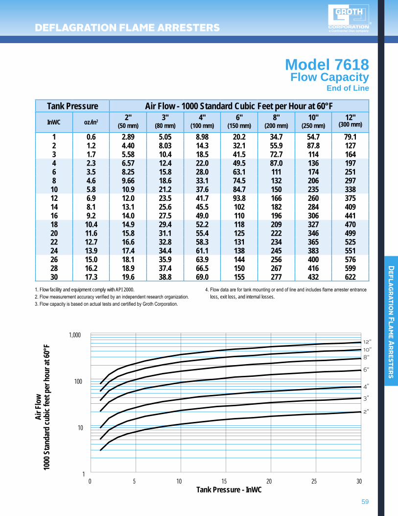
Model 7618Flow Capacity
End of Line
Tank Pressure Air Flow - 1000 Standard Cubic Feet per Hour at 60°FInWC oz/in2 2"
(50 mm)3"
(80 mm)4"
(100 mm)6"
(150 mm)8"
(200 mm)10"
(250 mm)12"
(300 mm)
1 0.6 2.89 5.05 8.98 20.2 34.7 54.7 79.12 1.2 4.40 8.03 14.3 32.1 55.9 87.8 1273 1.7 5.58 10.4 18.5 41.5 72.7 114 1644 2.3 6.57 12.4 22.0 49.5 87.0 136 1976 3.5 8.25 15.8 28.0 63.1 111 174 2518 4.6 9.66 18.6 33.1 74.5 132 206 29710 5.8 10.9 21.2 37.6 84.7 150 235 33812 6.9 12.0 23.5 41.7 93.8 166 260 37514 8.1 13.1 25.6 45.5 102 182 284 40916 9.2 14.0 27.5 49.0 110 196 306 44118 10.4 14.9 29.4 52.2 118 209 327 47020 11.6 15.8 31.1 55.4 125 222 346 49922 12.7 16.6 32.8 58.3 131 234 365 52524 13.9 17.4 34.4 61.1 138 245 383 55126 15.0 18.1 35.9 63.9 144 256 400 57628 16.2 18.9 37.4 66.5 150 267 416 59930 17.3 19.6 38.8 69.0 155 277 432 622
1. Flow facility and equipment comply with API 2000.2. Flow measurement accuracy verified by an independent research organization.3. Flow capacity is based on actual tests and certified by Groth Corporation.
4. Flow data are for tank mounting or end of line and includes flame arrester entrance loss, exit loss, and internal losses.
Air F
low
1000
Sta
ndar
d cu
bic f
eet p
er h
our a
t 60°
F
Tank Pressure - InWC
12"10"8"
6"
4"
3"
2"
60
Defl
agra
tion
Fla
me A
rres
ters
DeflaGraTiON flame arresTers
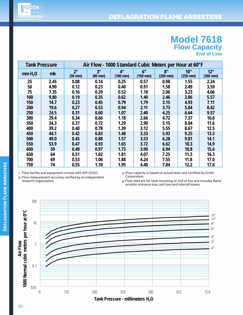
Model 7618Flow Capacity
End of Line
Tank Pressure Air Flow - 1000 Standard Cubic Meters per Hour at 60°Fmm H2O mb 2"
(50 mm)3"
(80 mm)4"
(100 mm)6"
(150 mm)8"
(200 mm)10"
(250 mm)12"
(300 mm)25 2.45 0.08 0.14 0.25 0.57 0.98 1.55 2.2450 4.90 0.12 0.23 0.40 0.91 1.58 2.49 3.5975 7.35 0.16 0.29 0.52 1.18 2.06 3.23 4.66100 9.80 0.19 0.35 0.62 1.40 2.46 3.86 5.57150 14.7 0.23 0.45 0.79 1.79 3.15 4.93 7.11200 19.6 0.27 0.53 0.94 2.11 3.73 5.84 8.42250 24.5 0.31 0.60 1.07 2.40 4.25 6.64 9.57300 29.4 0.34 0.66 1.18 2.66 4.72 7.37 10.6350 34.3 0.37 0.72 1.29 2.90 5.15 8.04 11.6400 39.2 0.40 0.78 1.39 3.12 5.55 8.67 12.5450 44.1 0.42 0.83 1.48 3.33 5.92 9.25 13.3500 49.0 0.45 0.88 1.57 3.53 6.28 9.81 14.1550 53.9 0.47 0.93 1.65 3.72 6.62 10.3 14.9600 59 0.49 0.97 1.73 3.90 6.94 10.8 15.6650 64 0.51 1.02 1.81 4.07 7.25 11.3 16.3700 69 0.53 1.06 1.88 4.24 7.55 11.8 17.0750 74 0.55 1.10 1.95 4.40 7.84 12.2 17.6
1.FlowfacilityandequipmentcomplywithAPI2000.2.Flowmeasurementaccuracyverifiedbyanindependent
researchorganization.
3. Flow capacity is based on actual tests and certified by Groth Corporation.
4. Flow data are for tank mounting or end of line and includes flame arrester entrance loss, exit loss and internal losses.
Air F
low
1000
Nor
mal
cubi
c met
ers p
er h
our a
t 0°C
Tank Pressure - millimeters H2O
12"10"8"6"
4"3"
2"
61
Deflagration Flame Arresters
DeflaGraTiON flame arresTers
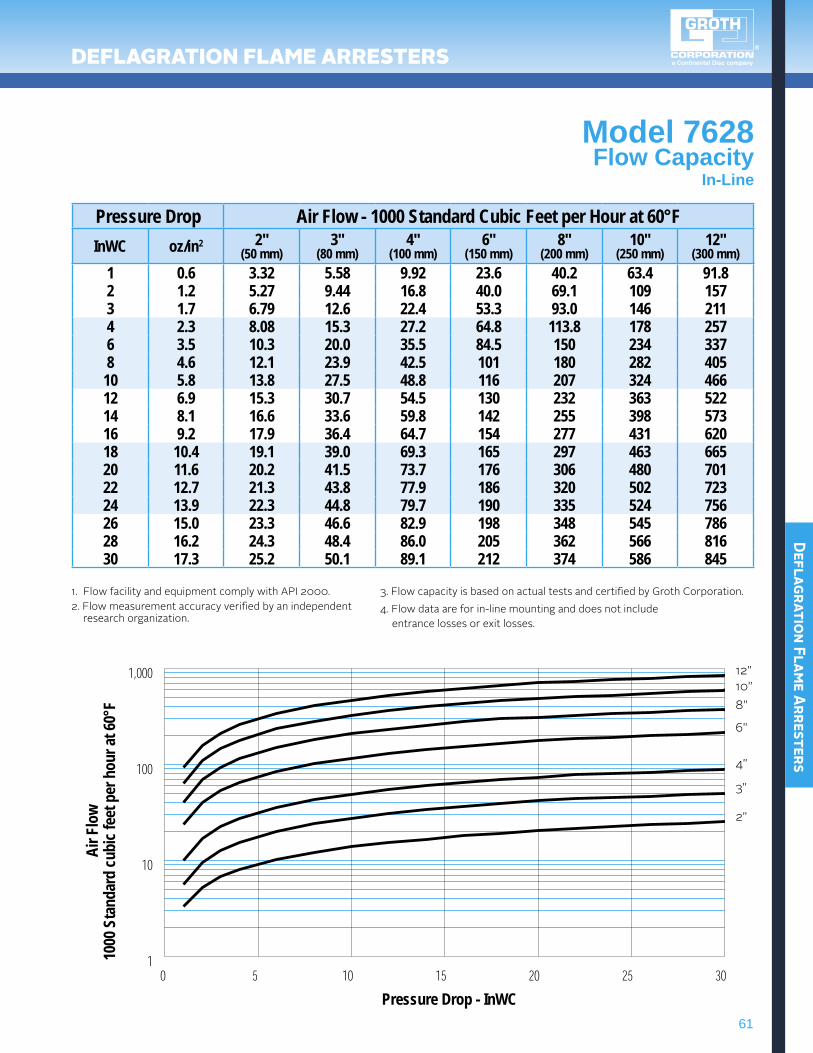
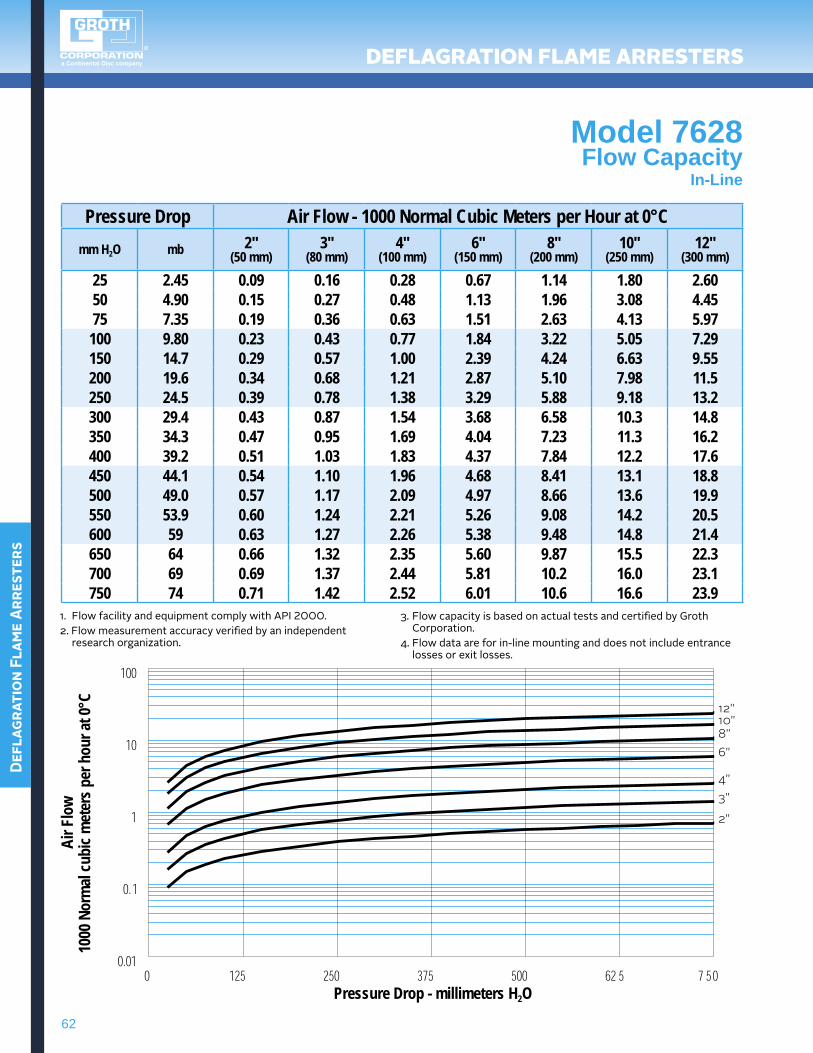
Model 7628Flow Capacity
In-Line
Pressure Drop Air Flow - 1000 Standard Cubic Feet per Hour at 60°FInWC oz/in2 2"
(50 mm)3"
(80 mm)4"
(100 mm)6"
(150 mm)8"
(200 mm)10"
(250 mm)12"
(300 mm)1 0.6 3.32 5.58 9.92 23.6 40.2 63.4 91.82 1.2 5.27 9.44 16.8 40.0 69.1 109 1573 1.7 6.79 12.6 22.4 53.3 93.0 146 2114 2.3 8.08 15.3 27.2 64.8 113.8 178 2576 3.5 10.3 20.0 35.5 84.5 150 234 3378 4.6 12.1 23.9 42.5 101 180 282 40510 5.8 13.8 27.5 48.8 116 207 324 46612 6.9 15.3 30.7 54.5 130 232 363 52214 8.1 16.6 33.6 59.8 142 255 398 57316 9.2 17.9 36.4 64.7 154 277 431 62018 10.4 19.1 39.0 69.3 165 297 463 66520 11.6 20.2 41.5 73.7 176 306 480 70122 12.7 21.3 43.8 77.9 186 320 502 72324 13.9 22.3 44.8 79.7 190 335 524 75626 15.0 23.3 46.6 82.9 198 348 545 78628 16.2 24.3 48.4 86.0 205 362 566 81630 17.3 25.2 50.1 89.1 212 374 586 845
1. Flow facility and equipment comply with API 2000.2. Flow measurement accuracy verified by an independent research organization.
3. Flow capacity is based on actual tests and certified by Groth Corporation.4. Flow data are for in-line mounting and does not include entrance losses or exit losses.
Air F
low
1000
Sta
ndar
d cu
bic f
eet p
er h
our a
t 60°
F
Pressure Drop - InWC
12"10"8"
6"
4"
3"
2"
62
Defl
agra
tion
Fla
me A
rres
ters
DeflaGraTiON flame arresTers
Model 7628Flow Capacity
In-Line
Pressure Drop Air Flow - 1000 Normal Cubic Meters per Hour at 0°Cmm H2O mb 2"
(50 mm)3"
(80 mm)4"
(100 mm)6"
(150 mm)8"
(200 mm)10"
(250 mm)12"
(300 mm)
25 2.45 0.09 0.16 0.28 0.67 1.14 1.80 2.6050 4.90 0.15 0.27 0.48 1.13 1.96 3.08 4.4575 7.35 0.19 0.36 0.63 1.51 2.63 4.13 5.97100 9.80 0.23 0.43 0.77 1.84 3.22 5.05 7.29150 14.7 0.29 0.57 1.00 2.39 4.24 6.63 9.55200 19.6 0.34 0.68 1.21 2.87 5.10 7.98 11.5250 24.5 0.39 0.78 1.38 3.29 5.88 9.18 13.2300 29.4 0.43 0.87 1.54 3.68 6.58 10.3 14.8350 34.3 0.47 0.95 1.69 4.04 7.23 11.3 16.2400 39.2 0.51 1.03 1.83 4.37 7.84 12.2 17.6450 44.1 0.54 1.10 1.96 4.68 8.41 13.1 18.8500 49.0 0.57 1.17 2.09 4.97 8.66 13.6 19.9550 53.9 0.60 1.24 2.21 5.26 9.08 14.2 20.5600 59 0.63 1.27 2.26 5.38 9.48 14.8 21.4650 64 0.66 1.32 2.35 5.60 9.87 15.5 22.3700 69 0.69 1.37 2.44 5.81 10.2 16.0 23.1750 74 0.71 1.42 2.52 6.01 10.6 16.6 23.9
1.FlowfacilityandequipmentcomplywithAPI2000.2.Flowmeasurementaccuracyverifiedbyanindependent
researchorganization.
3. Flow capacity is based on actual tests and certified by Groth Corporation.
4. Flow data are for in-line mounting and does not include entrance losses or exit losses.
Air F
low
1000
Nor
mal
cubi
c met
ers p
er h
our a
t 0°C
Pressure Drop - millimeters H2O
12"10"8"6"
4"3"
2"
64
Defl
agra
tion
Fla
me A
rres
ters
DeflaGraTiON flame arresTers / aTeX cerTifieD
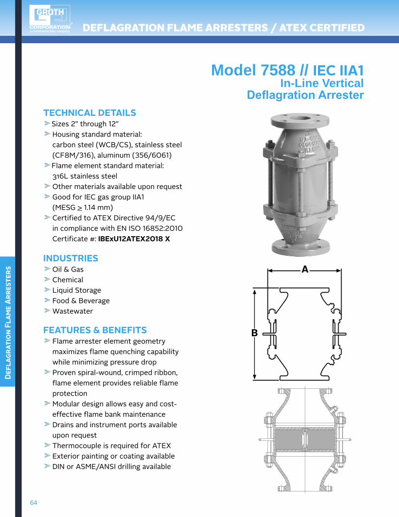
Model 7588 // IEc IIA1In-Line Vertical
DeflagrationArresterTEchNIcAL DETAILS
Sizes2"through12" Housing standard material:
carbon steel (WCB/CS), stainless steel (CF8M/316), aluminum (356/6061) Flame element standard material:
316Lstainlesssteel Other materials available upon request Good for IEC gas group IIA1
(MESG > 1.14 mm) Certified to ATEX Directive 94/9/EC
incompliancewithENISO16852:2010 Certificate#:IbExU12ATEX2018 X
INDUSTRIES Oil & Gas Chemical Liquid Storage Food & Beverage Wastewater
FEATURES & bENEFITS Flame arrester element geometry maximizesflamequenchingcapabilitywhileminimizingpressuredrop Proven spiral-wound, crimped ribbon, flame element provides reliable flame protection Modular design allows easy and cost-effective flame bank maintenance Drains and instrument ports available upon request Thermocouple is required for ATEX Exterior painting or coating availableDINorASME/ANSIdrillingavailable
A
b
65
Deflagration Flame Arresters
DeflaGraTiON flame arresTers / aTeX cerTifieD
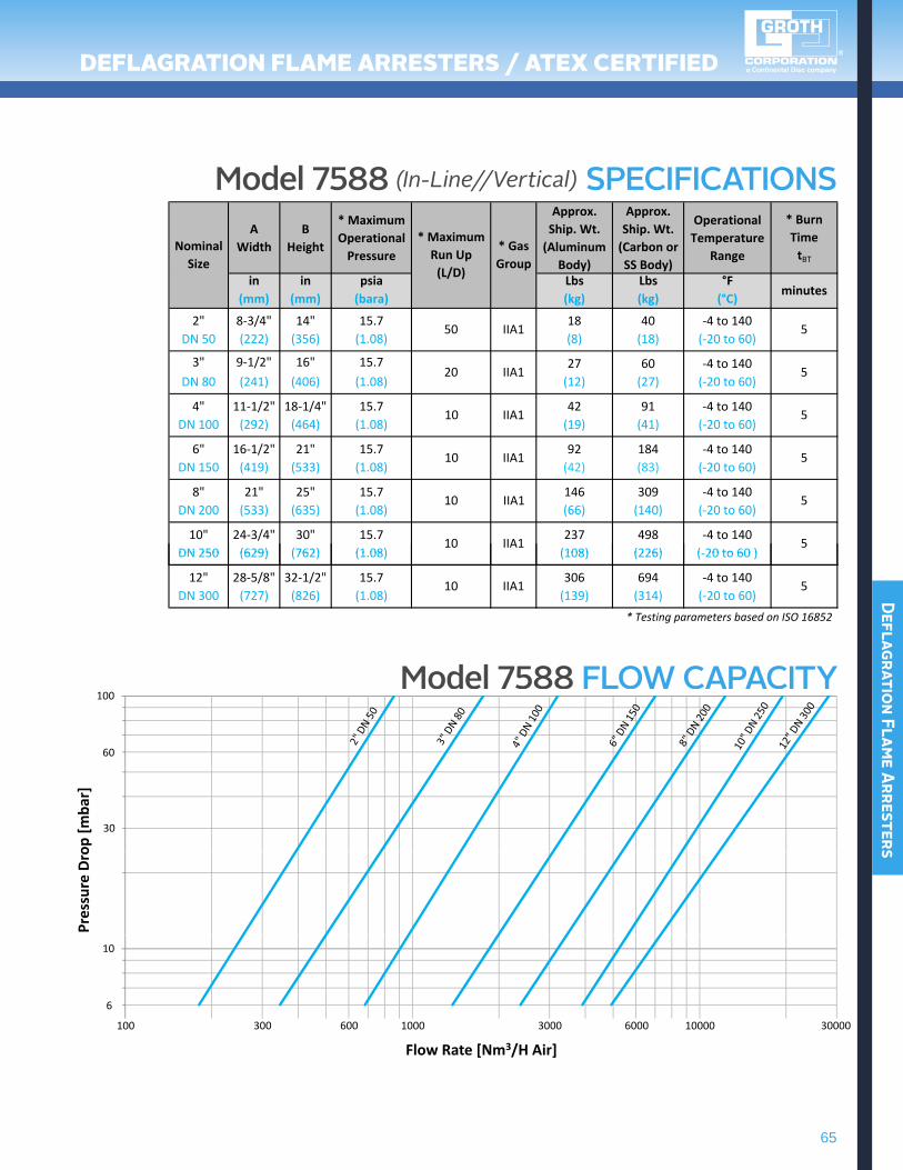
Model 7588 (In-Line//Vertical) SPECIFICATIONS
Model 7588 FLOW CAPACITY
AWidth
BHeight
* MaximumOperationalPressure
Approx.Ship. Wt.(Aluminum
Body)
Approx.Ship. Wt.(Carbon orSS Body)
OperationalTemperature
Range
* Burn TimetBT
in in psia Lbs Lbs °F(mm) (mm) (bara) (kg) (kg) (°C)
2" 8‐3/4" 14" 15.7 18 40 ‐4 to 140DN 50 (222) (356) (1.08) (8) (18) (‐20 to 60)
3" 9‐1/2" 16" 15.7 27 60 ‐4 to 140DN 80 (241) (406) (1.08) (12) (27) (‐20 to 60)
4" 11‐1/2" 18‐1/4" 15.7 42 91 ‐4 to 140DN 100 (292) (464) (1.08) (19) (41) (‐20 to 60)
6" 16‐1/2" 21" 15.7 92 184 ‐4 to 140DN 150 (419) (533) (1.08) (42) (83) (‐20 to 60)
8" 21" 25" 15.7 146 309 ‐4 to 140DN 200 (533) (635) (1.08) (66) (140) (‐20 to 60)
10" 24‐3/4" 30" 15.7 237 498 ‐4 to 140DN 250 (629) (762) (1 08) (108) (226) (‐20 to 60 )
IIA1
IIA110
10 IIA1
10 IIA1
10
IIA150
20 IIA1
NominalSize
* MaximumRun Up (L/D)
* GasGroup
minutes
5
5
5
5
5
5DN 250 (629) (762) (1.08) (108) (226) (‐20 to 60 )
12" 28‐5/8" 32‐1/2" 15.7 306 694 ‐4 to 140DN 300 (727) (826) (1.08) (139) (314) (‐20 to 60)
* Testing parameters based on ISO 16852
510 IIA1
100
60
op [m
bar]
30
Pres
sure
Dro
10
6
000010001001
Flow Rate [Nm3/H Air]0000300060003006003
66
Defl
agra
tion
Fla
me A
rres
ters
DeflaGraTiON flame arresTers / aTeX cerTifieD
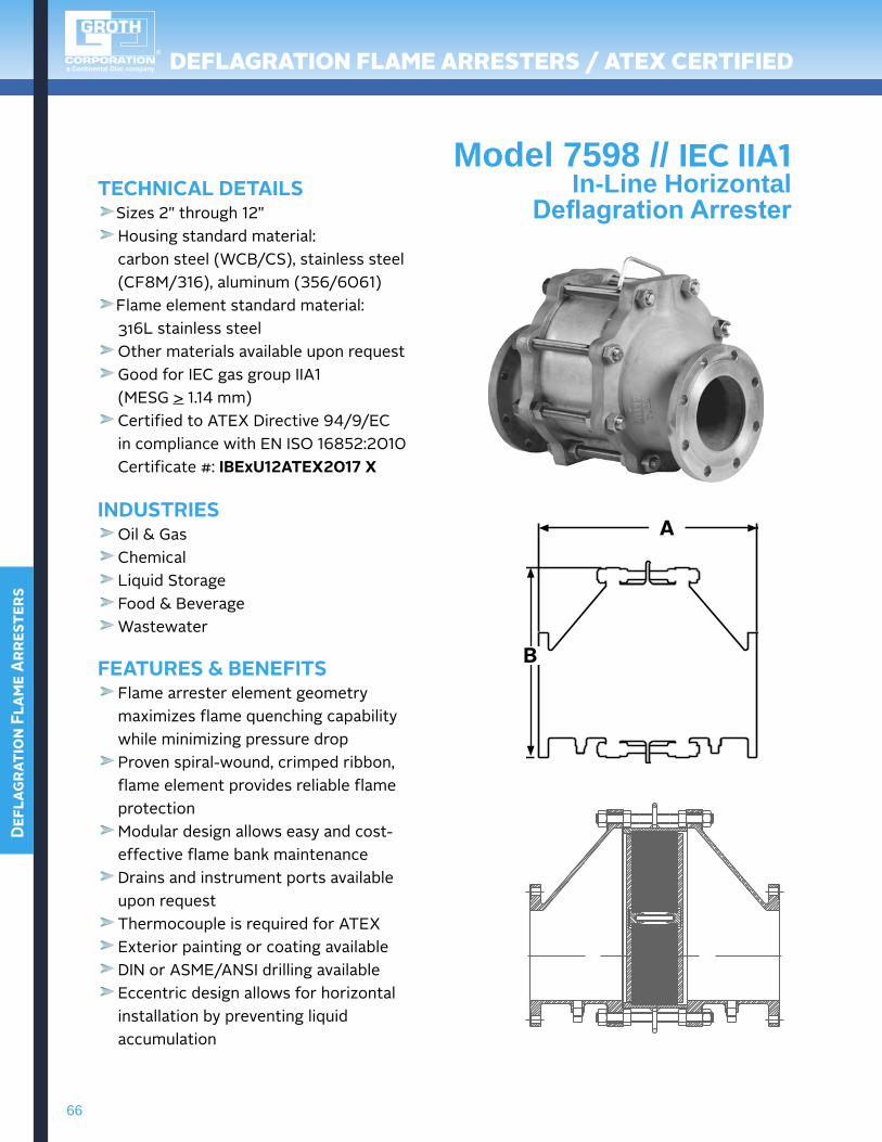
Model 7598 // IEc IIA1In-Line Horizontal
DeflagrationArresterTEchNIcAL DETAILS
Sizes2"through12" Housing standard material:
carbon steel (WCB/CS), stainless steel (CF8M/316), aluminum (356/6061) Flame element standard material:
316Lstainlesssteel Other materials available upon request Good for IEC gas group IIA1
(MESG > 1.14 mm) Certified to ATEX Directive 94/9/EC
incompliancewithENISO16852:2010 Certificate#:IbExU12ATEX2017 X
INDUSTRIES Oil & Gas Chemical Liquid Storage Food & Beverage Wastewater
FEATURES & bENEFITS Flame arrester element geometry maximizesflamequenchingcapabilitywhileminimizingpressuredrop Proven spiral-wound, crimped ribbon, flame element provides reliable flame protection Modular design allows easy and cost-effective flame bank maintenance Drains and instrument ports available upon request Thermocouple is required for ATEX Exterior painting or coating availableDINorASME/ANSIdrillingavailableEccentricdesignallowsforhorizontalinstallation by preventing liquid accumulation
A
b
67
Deflagration Flame Arresters
DeflaGraTiON flame arresTers / aTeX cerTifieD
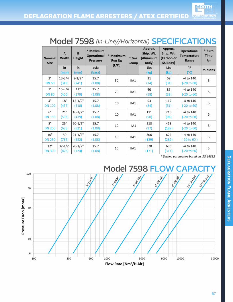
Model 7598 (In-Line//Horizontal) SPECIFICATIONSA
WidthB
Height
* MaximumOperationalPressure
Approx.Ship. Wt.(Aluminum
Body)
Approx.Ship. Wt.(Carbon orSS Body)
OperationalTemperature
Range
* Burn TimetBT
in in psia Lbs Lbs °F(mm) (mm) (bara) (kg) (kg) (°C)
2" 13‐3/4" 9‐1/2" 15.7 31 69 ‐4 to 140DN 50 (349) (241) (1.08) (14) (31) (‐20 to 60)
3" 15‐3/4" 11" 15.7 40 85 ‐4 to 140DN 80 (400) (279) (1.08) (18) (38) (‐20 to 60)
4" 18" 12‐1/2" 15.7 53 112 ‐4 to 140DN 100 (457) (318) (1.08) (24) (51) (‐20 to 60)
6" 21" 16‐1/2" 15.7 111 216 ‐4 to 140DN 150 (533) (419) (1.08) (50) (98) (‐20 to 60)
8" 25" 20‐1/2" 15.7 213 413 ‐4 to 140DN 200 (635) (521) (1.08) (97) (187) (‐20 to 60)
10" 30 24‐1/2" 15.7 306 622 ‐4 to 140DN 250 (762) (622) (1 08) (139) (282) ( 20 to 60 )
10 IIA1
10 IIA1
10 IIA1
10 IIA1
50 IIA1
20 IIA1
NominalSize
* MaximumRun Up (L/D)
* GasGroup
minutes
5
5
5
5
5
5DN 250 (762) (622) (1.08) (139) (282) (‐20 to 60 )
12" 32‐1/2" 28‐1/2" 15.7 378 693 ‐4 to 140DN 300 (826) (724) (1.08) (171) (314) (‐20 to 60)
* Testing parameters based on ISO 16852
510 IIA1
100
60
op [m
bar]
30
Pres
sure
Dro
10
6
000010001001
Flow Rate [Nm3/H Air]0000300060003006003
Model 7598 FLOW CAPACITY
68
Defl
agra
tion
Fla
me A
rres
ters
DeflaGraTiON flame arresTers / aTeX cerTifieD
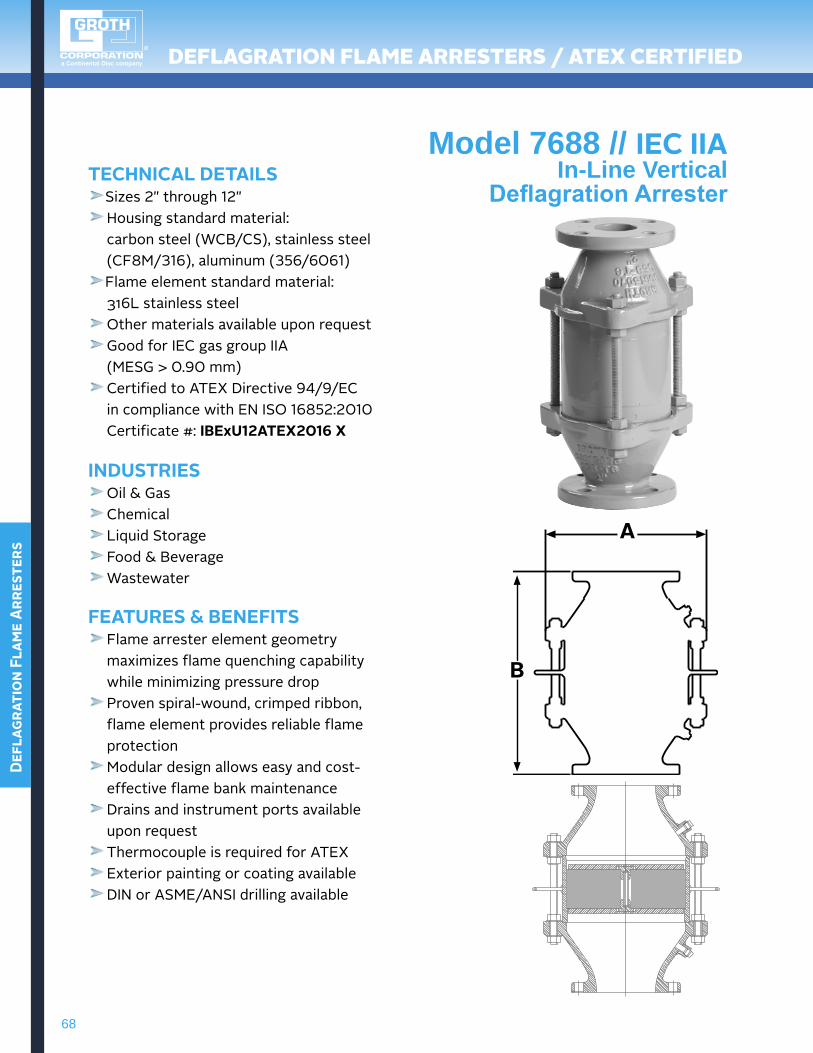
Model 7688 // IEc IIAIn-Line Vertical
DeflagrationArresterTEchNIcAL DETAILS
Sizes2"through12" Housing standard material:
carbon steel (WCB/CS), stainless steel (CF8M/316), aluminum (356/6061) Flame element standard material:
316Lstainlesssteel Other materials available upon request Good for IEC gas group IIA
(MESG > 0.90 mm) Certified to ATEX Directive 94/9/EC
incompliancewithENISO16852:2010 Certificate#:IbExU12ATEX2016 X
INDUSTRIES Oil & Gas Chemical Liquid Storage Food & Beverage Wastewater
FEATURES & bENEFITS Flame arrester element geometry maximizesflamequenchingcapabilitywhileminimizingpressuredrop Proven spiral-wound, crimped ribbon, flame element provides reliable flame protection Modular design allows easy and cost-effective flame bank maintenance Drains and instrument ports available upon request Thermocouple is required for ATEX Exterior painting or coating availableDINorASME/ANSIdrillingavailable
A
b
69
Deflagration Flame Arresters
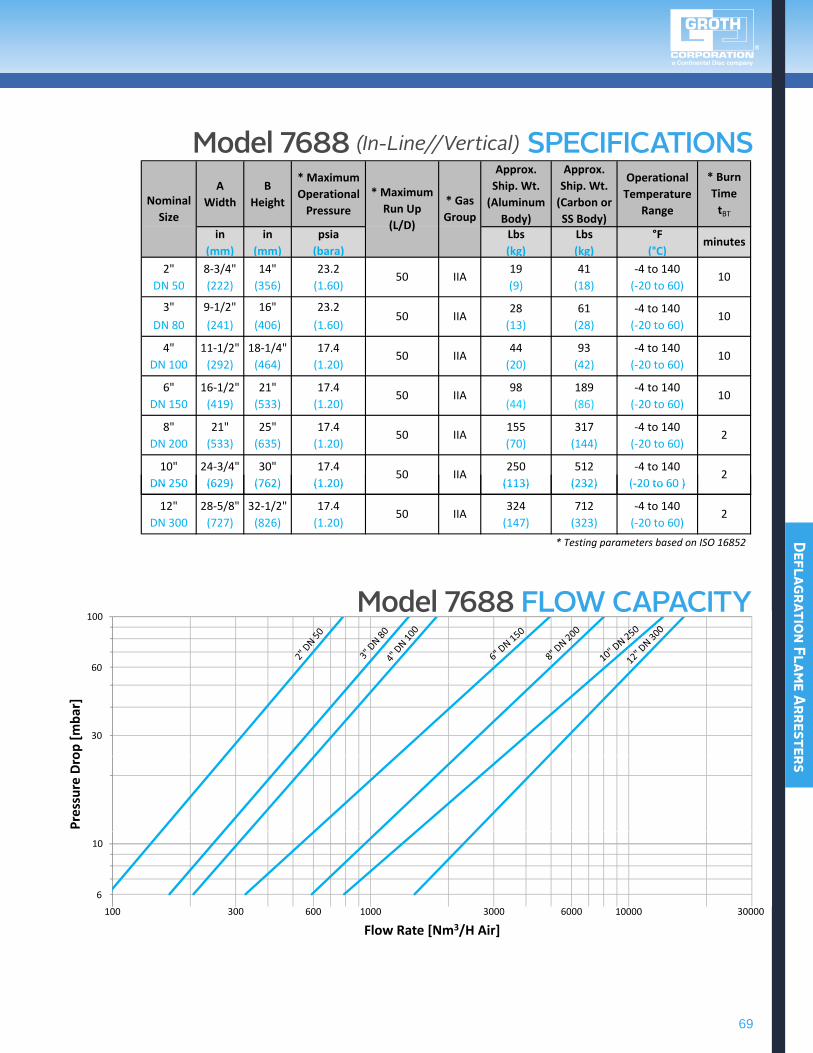
Model 7688 (In-Line//Vertical) SPECIFICATIONSA
WidthB
Height
* MaximumOperationalPressure
Approx.Ship. Wt.(Aluminum
Body)
Approx.Ship. Wt.(Carbon orSS Body)
OperationalTemperature
Range
* Burn TimetBT
in in psia Lbs Lbs °F(mm) (mm) (bara) (kg) (kg) (°C)
2" 8‐3/4" 14" 23.2 19 41 ‐4 to 140DN 50 (222) (356) (1.60) (9) (18) (‐20 to 60)
3" 9‐1/2" 16" 23.2 28 61 ‐4 to 140DN 80 (241) (406) (1.60) (13) (28) (‐20 to 60)
4" 11‐1/2" 18‐1/4" 17.4 44 93 ‐4 to 140DN 100 (292) (464) (1.20) (20) (42) (‐20 to 60)
6" 16‐1/2" 21" 17.4 98 189 ‐4 to 140DN 150 (419) (533) (1.20) (44) (86) (‐20 to 60)
8" 21" 25" 17.4 155 317 ‐4 to 140DN 200 (533) (635) (1.20) (70) (144) (‐20 to 60)
10" 24‐3/4" 30" 17.4 250 512 ‐4 to 140DN 250 (629) (762) (1.20) (113) (232) (‐20 to 60 )
50 IIA
50 IIA
50 IIA
50 IIA
50 IIA
50 IIA
NominalSize
* MaximumRun Up (L/D)
* GasGroup
minutes
10
10
10
10
2
2DN 250 (629) (762) (1.20) (113) (232) (‐20 to 60 )
12" 28‐5/8" 32‐1/2" 17.4 324 712 ‐4 to 140DN 300 (727) (826) (1.20) (147) (323) (‐20 to 60)
* Testing parameters based on ISO 16852
250 IIA
100
60
op [m
bar]
30
Pres
sure
Dro
10
6
000010001001
Flow Rate [Nm3/H Air]0000300060003006003
Model 7688 FLOW CAPACITY
70
Defl
agra
tion
Fla
me A
rres
ters
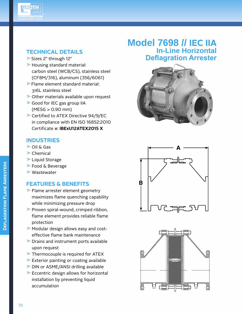
Model 7698 // IEc IIAIn-Line Horizontal
DeflagrationArresterTEchNIcAL DETAILS
Sizes2"through12" Housing standard material:
carbon steel (WCB/CS), stainless steel (CF8M/316), aluminum (356/6061) Flame element standard material:
316Lstainlesssteel Other materials available upon request Good for IEC gas group IIA
(MESG > 0.90 mm) Certified to ATEX Directive 94/9/EC
incompliancewithENISO16852:2010 Certificate#:IbExU12ATEX2015 X
INDUSTRIES Oil & Gas Chemical Liquid Storage Food & Beverage Wastewater
FEATURES & bENEFITS Flame arrester element geometry maximizesflamequenchingcapabilitywhileminimizingpressuredrop Proven spiral-wound, crimped ribbon, flame element provides reliable flame protection Modular design allows easy and cost-effective flame bank maintenance Drains and instrument ports available upon request Thermocouple is required for ATEX Exterior painting or coating availableDINorASME/ANSIdrillingavailableEccentricdesignallowsforhorizontalinstallation by preventing liquid accumulation
A
b
71
Deflagration Flame Arresters
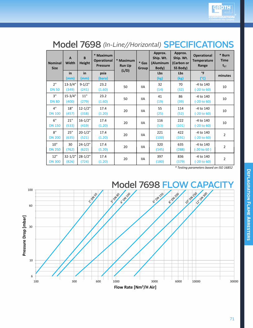
Model 7698 (In-Line//Horizontal) SPECIFICATIONSA
WidthB
Height
* MaximumOperationalPressure
Approx.Ship. Wt.(Aluminum
Body)
Approx.Ship. Wt.(Carbon orSS Body)
OperationalTemperature
Range
* Burn TimetBT
in in psia Lbs Lbs °F(mm) (mm) (bara) (kg) (kg) (°C)
2" 13‐3/4" 9‐1/2" 23.2 32 70 ‐4 to 140DN 50 (349) (241) (1.60) (14) (32) (‐20 to 60)
3" 15‐3/4" 11" 23.2 41 86 ‐4 to 140DN 80 (400) (279) (1.60) (19) (39) (‐20 to 60)
4" 18" 12‐1/2" 17.4 55 114 ‐4 to 140DN 100 (457) (318) (1.20) (25) (52) (‐20 to 60)
6" 21" 16‐1/2" 17.4 116 222 ‐4 to 140DN 150 (533) (419) (1.20) (53) (101) (‐20 to 60)
8" 25" 20‐1/2" 17.4 221 422 ‐4 to 140DN 200 (635) (521) (1.20) (100) (191) (‐20 to 60)
10" 30 24‐1/2" 17.4 320 635 ‐4 to 140DN 250 (762) (622) (1 20) (145) (288) ( 20 to 60 )
20 IIA
20 IIA
20 IIA
20 IIA
50 IIA
50 IIA
NominalSize
* MaximumRun Up (L/D)
* GasGroup
minutes
10
10
10
10
2
2DN 250 (762) (622) (1.20) (145) (288) (‐20 to 60 )
12" 32‐1/2" 28‐1/2" 17.4 397 836 ‐4 to 140DN 300 (826) (724) (1.20) (180) (379) (‐20 to 60)
* Testing parameters based on ISO 16852
220 IIA
100
60
op [m
bar]
30
Pres
sure
Dro
10
6
000010001001
Flow Rate [Nm3/H Air]0000300060003006003
Model 7698 FLOW CAPACITY
72
Defl
agra
tion
Fla
me A
rres
ters
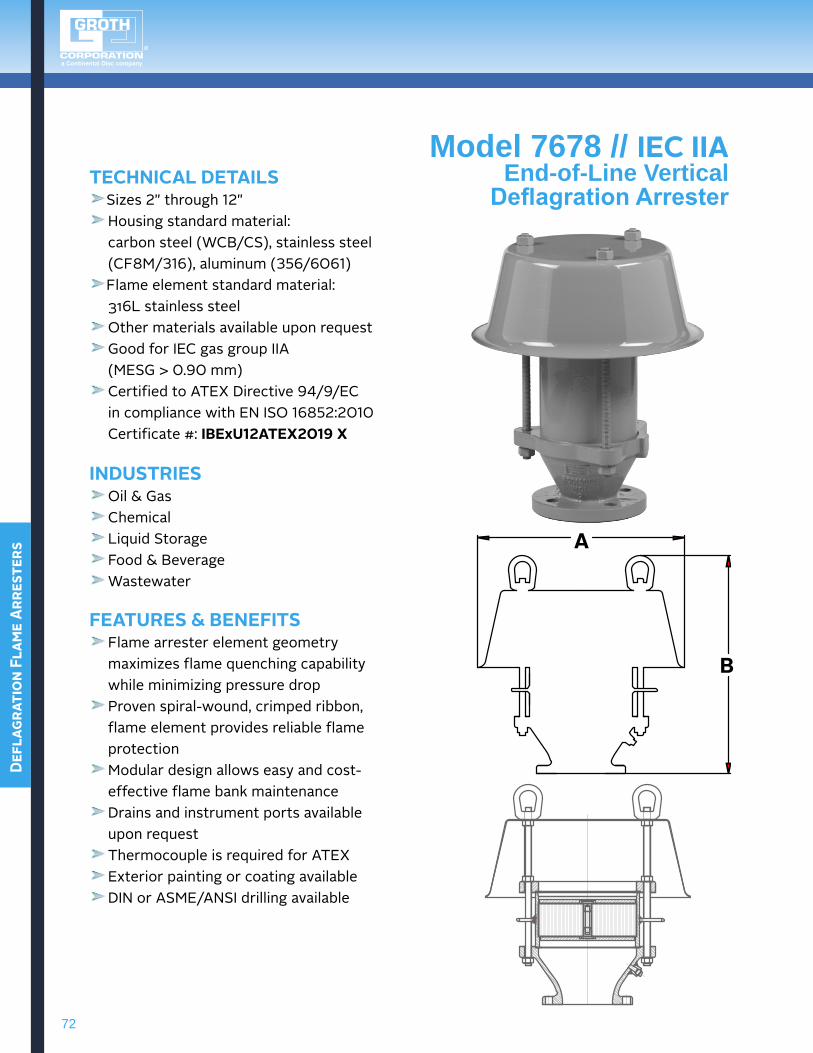
Model 7678 // IEc IIAEnd-of-Line VerticalDeflagrationArrester
TEchNIcAL DETAILSSizes2"through12" Housing standard material:
carbon steel (WCB/CS), stainless steel (CF8M/316), aluminum (356/6061) Flame element standard material:
316Lstainlesssteel Other materials available upon request Good for IEC gas group IIA
(MESG > 0.90 mm) Certified to ATEX Directive 94/9/EC
incompliancewithENISO16852:2010 Certificate#:IbExU12ATEX2019 X
INDUSTRIES Oil & Gas Chemical Liquid Storage Food & Beverage Wastewater
FEATURES & bENEFITS Flame arrester element geometry maximizesflamequenchingcapabilitywhileminimizingpressuredrop Proven spiral-wound, crimped ribbon, flame element provides reliable flame protection Modular design allows easy and cost-effective flame bank maintenance Drains and instrument ports available upon request Thermocouple is required for ATEX Exterior painting or coating availableDINorASME/ANSIdrillingavailable
A
b
73
Deflagration Flame Arresters
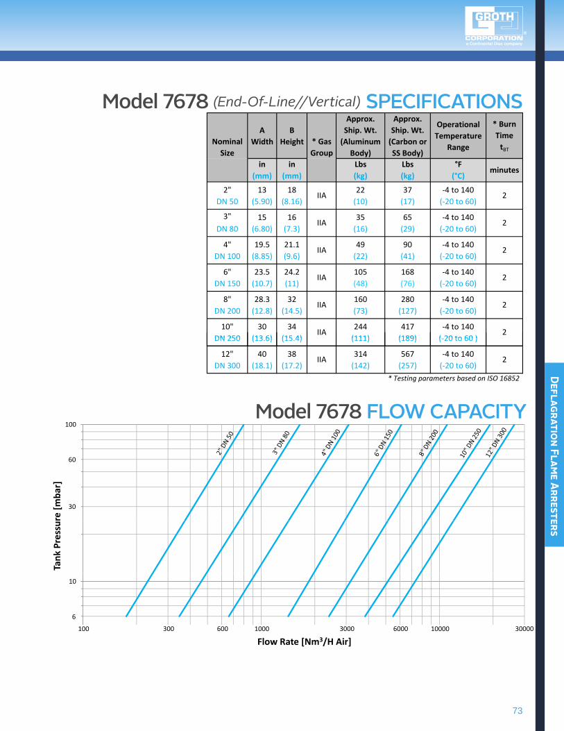
Model 7678 (End-Of-Line//Vertical) SPECIFICATIONSA
WidthB
Height
Approx.Ship. Wt.(Aluminum
Body)
Approx.Ship. Wt.(Carbon orSS Body)
OperationalTemperature
Range
* Burn TimetBT
in in Lbs Lbs °F(mm) (mm) (kg) (kg) (°C)
2" 13 18 22 37 ‐4 to 140DN 50 (5.90) (8.16) (10) (17) (‐20 to 60)
3" 15 16 35 65 ‐4 to 140DN 80 (6.80) (7.3) (16) (29) (‐20 to 60)
4" 19.5 21.1 49 90 ‐4 to 140DN 100 (8.85) (9.6) (22) (41) (‐20 to 60)
6" 23.5 24.2 105 168 ‐4 to 140DN 150 (10.7) (11) (48) (76) (‐20 to 60)
8" 28.3 32 160 280 ‐4 to 140DN 200 (12.8) (14.5) (73) (127) (‐20 to 60)
10" 30 34 244 417 ‐4 to 140DN 250 (13 6) (15 4) (111) (189) ( 20 to 60 )
IIA
IIA
IIA
IIA
IIA
IIA
NominalSize
* GasGroup
minutes
2
2
2
2
2
2DN 250 (13.6) (15.4) (111) (189) (‐20 to 60 )
12" 40 38 314 567 ‐4 to 140DN 300 (18.1) (17.2) (142) (257) (‐20 to 60)
* Testing parameters based on ISO 16852
IIA 2
100
60
re [m
bar]
30
Tank
Pre
ssu
10
6
000010001001
Flow Rate [Nm3/H Air]0000300060003006003
Model 7678 FLOW CAPACITY
75
Detonation Flame Arresters
DeTONaTiON flame arresTers
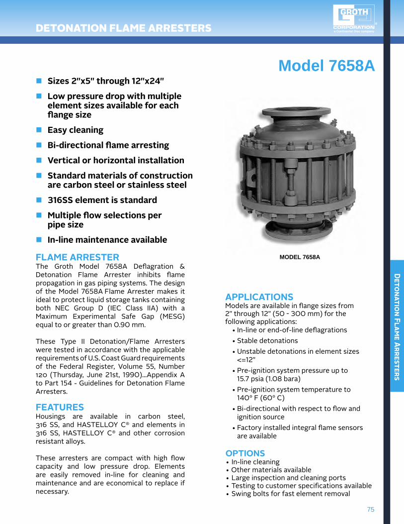
Model 7658An Sizes 2"x5" through 12"x24"
n Low pressure drop with multiple element sizes available for each flange size
n Easy cleaning
n bi-directional flame arresting
n Vertical or horizontal installation
n Standard materials of construction are carbon steel or stainless steel
n 316SS element is standard
n Multiple flow selections per pipe size
n In-line maintenance available
MODEL 7658AFLAME ARRESTERThe Groth Model 7658A Deflagration & Detonation Flame Arrester inhibits flame propagation in gas piping systems. The design of the Model 7658A Flame Arrester makes it ideal to protect liquid storage tanks containing both NEC Group D (IEC Class IIA) with aMaximum Experimental Safe Gap (MESG) equal to or greater than 0.90 mm.
These Type II Detonation/Flame Arresters were tested in accordance with the applicable requirements of U.S. Coast Guard requirements of the Federal Register, Volume 55, Number120 (Thursday, June21st, 1990)...Appendix A to Part 154 - Guidelines for Detonation Flame Arresters.
FEATURESHousings are available in carbon steel, 316SS, andHASTELLOy C® and elements in 316 SS, HASTELLOy C® and other corrosion resistant alloys.
These arresters are compact with high flow capacity and low pressure drop. Elements are easily removed in-line for cleaning and maintenance and are economical to replace if necessary.
APPLIcATIONSModelsareavailableinflangesizesfrom2"through12"(50 - 300 mm) for the following applications:
•In-lineorend-of-linedeflagrations•Stabledetonations•Unstabledetonationsinelementsizes<=12"
•Pre-ignitionsystempressureupto 15.7 psia (1.08 bara)
•Pre-ignitionsystemtemperatureto 140° F (60° C)
•Bi-directionalwithrespecttoflowand ignition source
•Factoryinstalledintegralflamesensors are available
OPTIONS•In-linecleaning•Othermaterialsavailable•Largeinspectionandcleaningports•Testingtocustomerspecificationsavailable•Swingboltsforfastelementremoval
76
Deto
nati
on F
lame
Arr
este
rs
DeTONaTiON flame arresTers
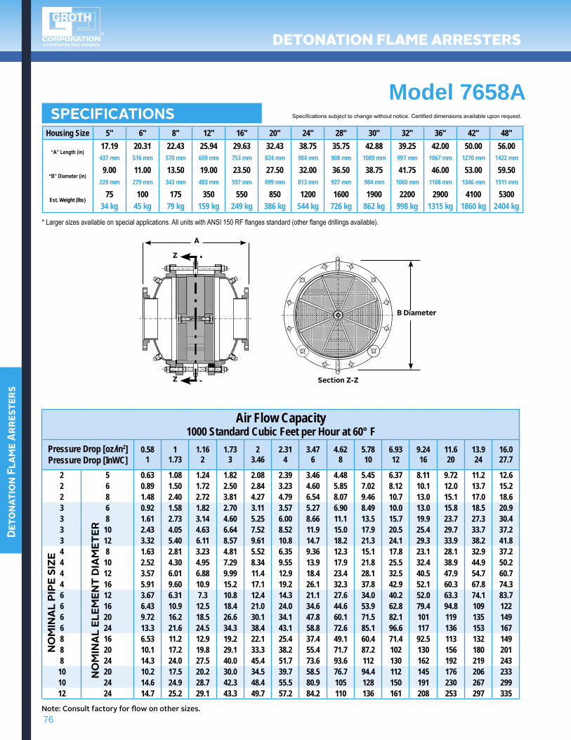
SPEcIFIcATIONS Specifications subject to change without notice. Certified dimensions available upon request.
Housing Size 5" 6" 8" 12" 16" 20" 24" 28" 30" 32" 36" 42" 48"
“A” Length (in)17.19 20.31 22.43 25.94 29.63 32.43 38.75 35.75 42.88 39.25 42.00 50.00 56.00437 mm 516 mm 570 mm 659 mm 753 mm 824 mm 984 mm 908 mm 1089 mm 997 mm 1067 mm 1270 mm 1422 mm
“B” Diameter (in)9.00 11.00 13.50 19.00 23.50 27.50 32.00 36.50 38.75 41.75 46.00 53.00 59.50
229 mm 279 mm 343 mm 483 mm 597 mm 699 mm 813 mm 927 mm 984 mm 1060 mm 1168 mm 1346 mm 1511 mm
Est. Weight (lbs)75 100 175 350 550 850 1200 1600 1900 2200 2900 4100 5300
34 kg 45 kg 79 kg 159 kg 249 kg 386 kg 544 kg 726 kg 862 kg 998 kg 1315 kg 1860 kg 2404 kg
Air Flow Capacity1000 Standard Cubic Feet per Hour at 60° F
Pressure Drop [oz/in2]Pressure Drop [InWC]
0.581
11.73
1.162
1.733
23.46
2.314
3.476
4.628
5.7810
6.9312
9.2416
11.620
13.924
16.027.7
2 5 0.63 1.08 1.24 1.82 2.08 2.39 3.46 4.48 5.45 6.37 8.11 9.72 11.2 12.62 6 0.89 1.50 1.72 2.50 2.84 3.23 4.60 5.85 7.02 8.12 10.1 12.0 13.7 15.22 8 1.48 2.40 2.72 3.81 4.27 4.79 6.54 8.07 9.46 10.7 13.0 15.1 17.0 18.63 6 0.92 1.58 1.82 2.70 3.11 3.57 5.27 6.90 8.49 10.0 13.0 15.8 18.5 20.93 8 1.61 2.73 3.14 4.60 5.25 6.00 8.66 11.1 13.5 15.7 19.9 23.7 27.3 30.43 10 2.43 4.05 4.63 6.64 7.52 8.52 11.9 15.0 17.9 20.5 25.4 29.7 33.7 37.23 12 3.32 5.40 6.11 8.57 9.61 10.8 14.7 18.2 21.3 24.1 29.3 33.9 38.2 41.84 8 1.63 2.81 3.23 4.81 5.52 6.35 9.36 12.3 15.1 17.8 23.1 28.1 32.9 37.24 10 2.52 4.30 4.95 7.29 8.34 9.55 13.9 17.9 21.8 25.5 32.4 38.9 44.9 50.24 12 3.57 6.01 6.88 9.99 11.4 12.9 18.4 23.4 28.1 32.5 40.5 47.9 54.7 60.74 16 5.91 9.60 10.9 15.2 17.1 19.2 26.1 32.3 37.8 42.9 52.1 60.3 67.8 74.36 12 3.67 6.31 7.3 10.8 12.4 14.3 21.1 27.6 34.0 40.2 52.0 63.3 74.1 83.76 16 6.43 10.9 12.5 18.4 21.0 24.0 34.6 44.6 53.9 62.8 79.4 94.8 109 1226 20 9.72 16.2 18.5 26.6 30.1 34.1 47.8 60.1 71.5 82.1 101 119 135 1496 24 13.3 21.6 24.5 34.3 38.4 43.1 58.8 72.6 85.1 96.6 117 136 153 1678 16 6.53 11.2 12.9 19.2 22.1 25.4 37.4 49.1 60.4 71.4 92.5 113 132 1498 20 10.1 17.2 19.8 29.1 33.3 38.2 55.4 71.7 87.2 102 130 156 180 2018 24 14.3 24.0 27.5 40.0 45.4 51.7 73.6 93.6 112 130 162 192 219 243
10 20 10.2 17.5 20.2 30.0 34.5 39.7 58.5 76.7 94.4 112 145 176 206 23310 24 14.6 24.9 28.7 42.3 48.4 55.5 80.9 105 128 150 191 230 267 29912 24 14.7 25.2 29.1 43.3 49.7 57.2 84.2 110 136 161 208 253 297 335
NO
MIN
AL
PIPE
SIZ
E
NO
MIN
AL
ELEM
ENT
DIA
MET
ER
Note: Consult factory for flow on other sizes.
Z
Z
A
b Diameter
Section Z-Z
* Larger sizes available on special applications. All units with ANSI 150 RF flanges standard (other flange drillings available).
Model 7658A
77
Detonation Flame Arresters
DeTONaTiON flame arresTers
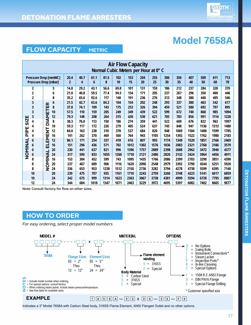
Model 7658AFLOw cAPAcITY METRIc
Air Flow CapacityNormal Cubic Meters per Hour at 0° C
Pressure Drop [mmWC]Pressure Drop [mbar]
20.42
40.74
61.16
81.58
10210
15315
20420
25525
30630
35635
40740
50950
61160
71370
2 5 14.8 29.2 43.1 56.6 69.8 101 131 159 186 212 237 284 328 3702 6 21.0 40.8 59.5 77.4 94.5 134 171 205 237 267 296 350 400 4462 8 35.2 65.6 92.6 117 140 191 236 276 313 348 380 440 495 5463 6 21.5 42.7 63.6 84.2 104 154 202 248 293 337 380 463 542 6173 8 37.8 74.1 109 143 175 253 326 394 459 521 580 692 797 8953 10 57.5 110 159 205 249 349 439 522 599 672 740 868 985 10943 12 79.3 148 208 264 315 430 530 621 705 783 856 991 1114 12284 8 38.3 76.0 113 150 186 274 359 441 522 600 676 822 963 10974 10 59.3 117 172 226 279 405 524 637 745 848 947 1136 1313 14804 12 84.0 163 238 310 378 537 684 820 948 1069 1184 1400 1599 17854 16 141 262 370 469 560 764 943 1105 1254 1392 1522 1762 1980 21836 12 86.1 171 254 337 418 616 807 993 1174 1349 1520 1851 2166 24696 16 151 296 436 571 702 1012 1302 1576 1836 2083 2321 2768 3186 35796 20 230 441 637 821 996 1396 1757 2089 2398 2688 2962 3472 3940 43776 24 317 590 833 1055 1260 1718 2121 2486 2820 3132 3424 3964 4456 49118 16 153 304 452 599 743 1095 1435 1766 2086 2399 2703 3290 3851 43908 20 237 467 689 906 1116 1620 2096 2548 2979 3392 3790 4544 5251 59208 24 336 653 953 1238 1512 2150 2736 3282 3794 4278 4738 5599 6395 7140
10 20 239 475 707 935 1161 1710 2243 2759 3260 3748 4223 5141 6017 685910 24 342 675 999 1314 1623 2363 3067 3738 4381 4999 5594 6728 7795 880712 24 344 684 1018 1347 1671 2463 3229 3972 4695 5397 6082 7402 8665 9877
NO
MIN
AL
PIPE
SIZ
E
NO
MIN
AL
ELEM
ENT
DIA
MET
ER
hOw TO ORDERFor easy ordering, select proper model numbers
MODEL # MATERIAL OPTIONS
7658A
Body Material3 = Carbon Steel5 = 316SSZ = Special
Flame elementwinding5 = 316SSZ = Special
Flange Sizes02 = 2" Thru12 = 12"
Element Sizes05 = 5" Thru24 = 24"
• Include model number when ordering.• For special options, consult factory.• When ordering steam jacket, include steam pressure/temperature.• See flow table for available sizes.N
OT
ES
EXAMPLEIndicates a 3" Model 7658A with Carbon Steel body, 316SS Flame Element, ANSI Flanged Outlet and no other options.
7 6 5 8 A 0 3 0 03 F6 65 0— x — —
x
Note: Consult factory for flow on other sizes.
O = No OptionsS = Swing BoltsI = Instrument Connections*J = Steam JacketP = Inspection Ports*R = In-line CleaningZ = Special Options
F = 150# R.F. ANSI FlangeD = DIN PN16 FlangeZ = Special Flange Drilling
* Customer specified size
79
Detonation Flame Arresters
This page intentionally left blank.
DeTONaTiON flame arresTers
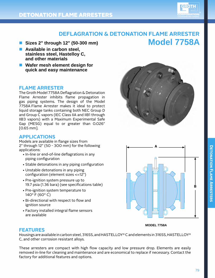
DEFLAgRATION & DETONATION FLAME ARRESTERModel 7758An Sizes 2" through 12" (50-300 mm)
n Available in carbon steel, stainless steel, Hastelloy C, and other materials
n Wafer mesh element design for quick and easy maintenance
FLAME ARRESTERThe Groth Model 7758A Deflagration & Detonation Flame Arrester inhibits flame propagation in gas piping systems. The design of the Model 7758A Flame Arrester makes it ideal to protect liquidstoragetankscontainingbothNECGroupDand Group C vapors (IEC Class IIA and IIB1 through IIB3 vapors) with a Maximum Experimental Safe Gap (MESG) equal to or greater than 0.026" [0.65 mm].
APPLIcATIONSModelsareavailableinflangesizesfrom 2"through12"(50 - 300 mm) for the following applications:
•In-lineorend-of-linedeflagrationsinany piping configuration
•Stabledetonationsinanypipingconfiguration•Unstabledetonationsinanypipingconfiguration(elementsizes<=12")
•Pre-ignitionsystempressureupto 19.7 psia (1.36 bara) (see specifications table)
•Pre-ignitionsystemtemperatureto 140° F (60° C)
•Bi-directionalwithrespecttoflowand ignition source
•Factoryinstalledintegralflamesensors are available
MODEL 7758AFEATURESHousings are available in carbon steel, 316SS, and HASTELLOy® C and elements in 316SS, HASTELLOy® C, and other corrosion resistant alloys.
These arresters are compact with high flow capacity and low pressure drop. Elements are easily removed in-line for cleaning and maintenance and are economical to replace if necessary. Contact the factory for additional features and options.
A
b
80
Deto
nati
on F
lame
Arr
este
rs
DeTONaTiON flame arresTers
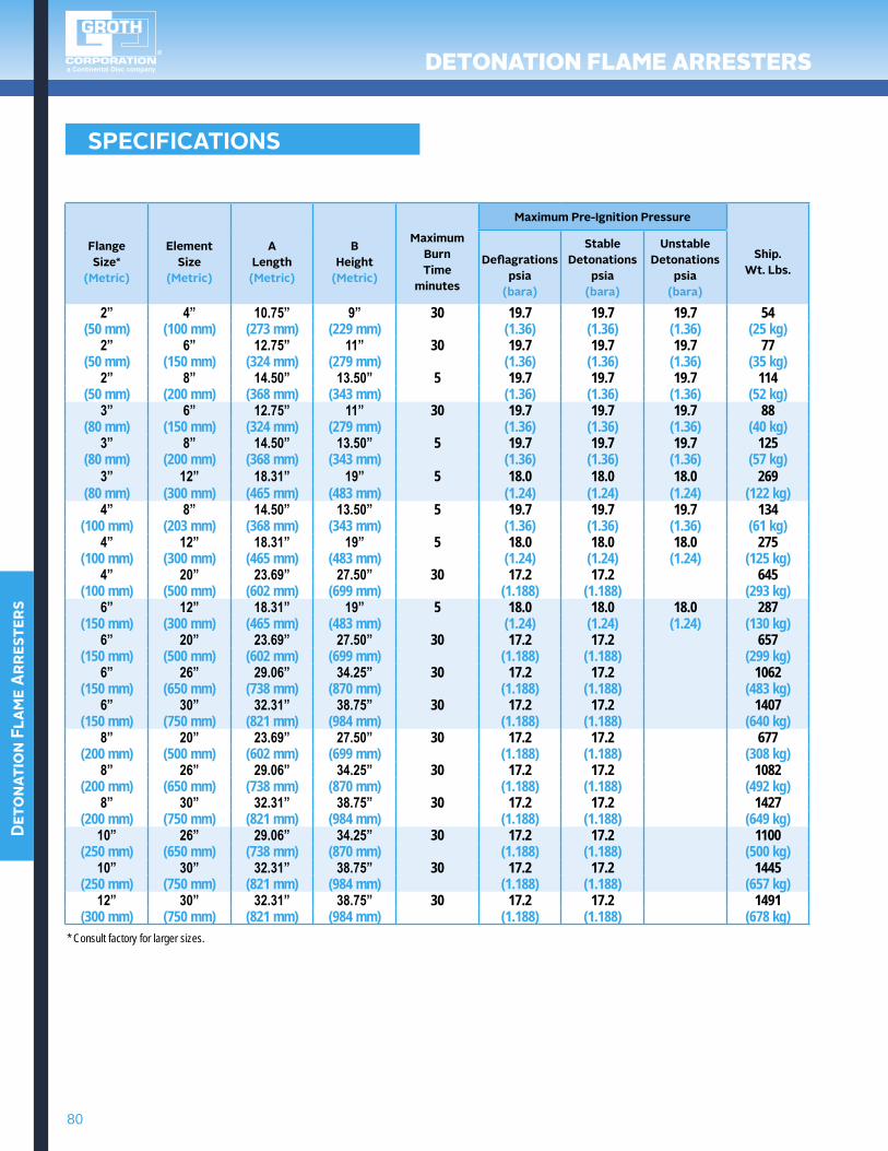
SPEcIFIcATIONS
FlangeSize*
(Metric)
ElementSize
(Metric)
ALength
(Metric)
bheight
(Metric)
MaximumburnTime
minutes
Maximum Pre-Ignition Pressure
Ship.wt. Lbs.
Deflagrationspsia
(bara)
Stable Detonations
psia(bara)
Unstable Detonations
psia(bara)
2” 4” 10.75” 9” 30 19.7 19.7 19.7 54(50 mm) (100 mm) (273 mm) (229 mm) (1.36) (1.36) (1.36) (25 kg)
2” 6” 12.75” 11” 30 19.7 19.7 19.7 77(50 mm) (150 mm) (324 mm) (279 mm) (1.36) (1.36) (1.36) (35 kg)
2” 8” 14.50” 13.50” 5 19.7 19.7 19.7 114(50 mm) (200 mm) (368 mm) (343 mm) (1.36) (1.36) (1.36) (52 kg)
3” 6” 12.75” 11” 30 19.7 19.7 19.7 88(80 mm) (150 mm) (324 mm) (279 mm) (1.36) (1.36) (1.36) (40 kg)
3” 8” 14.50” 13.50” 5 19.7 19.7 19.7 125(80 mm) (200 mm) (368 mm) (343 mm) (1.36) (1.36) (1.36) (57 kg)
3” 12” 18.31” 19” 5 18.0 18.0 18.0 269(80 mm) (300 mm) (465 mm) (483 mm) (1.24) (1.24) (1.24) (122 kg)
4” 8” 14.50” 13.50” 5 19.7 19.7 19.7 134(100 mm) (203 mm) (368 mm) (343 mm) (1.36) (1.36) (1.36) (61 kg)
4” 12” 18.31” 19” 5 18.0 18.0 18.0 275(100 mm) (300 mm) (465 mm) (483 mm) (1.24) (1.24) (1.24) (125 kg)
4” 20” 23.69” 27.50” 30 17.2 17.2 645(100 mm) (500 mm) (602 mm) (699 mm) (1.188) (1.188) (293 kg)
6” 12” 18.31” 19” 5 18.0 18.0 18.0 287(150 mm) (300 mm) (465 mm) (483 mm) (1.24) (1.24) (1.24) (130 kg)
6” 20” 23.69” 27.50” 30 17.2 17.2 657(150 mm) (500 mm) (602 mm) (699 mm) (1.188) (1.188) (299 kg)
6” 26” 29.06” 34.25” 30 17.2 17.2 1062(150 mm) (650 mm) (738 mm) (870 mm) (1.188) (1.188) (483 kg)
6” 30” 32.31” 38.75” 30 17.2 17.2 1407(150 mm) (750 mm) (821 mm) (984 mm) (1.188) (1.188) (640 kg)
8” 20” 23.69” 27.50” 30 17.2 17.2 677(200 mm) (500 mm) (602 mm) (699 mm) (1.188) (1.188) (308 kg)
8” 26” 29.06” 34.25” 30 17.2 17.2 1082(200 mm) (650 mm) (738 mm) (870 mm) (1.188) (1.188) (492 kg)
8” 30” 32.31” 38.75” 30 17.2 17.2 1427(200 mm) (750 mm) (821 mm) (984 mm) (1.188) (1.188) (649 kg)
10” 26” 29.06” 34.25” 30 17.2 17.2 1100(250 mm) (650 mm) (738 mm) (870 mm) (1.188) (1.188) (500 kg)
10” 30” 32.31” 38.75” 30 17.2 17.2 1445(250 mm) (750 mm) (821 mm) (984 mm) (1.188) (1.188) (657 kg)
12” 30” 32.31” 38.75” 30 17.2 17.2 1491(300 mm) (750 mm) (821 mm) (984 mm) (1.188) (1.188) (678 kg)
* Consult factory for larger sizes.
81
Detonation Flame Arresters
DeTONaTiON flame arresTers
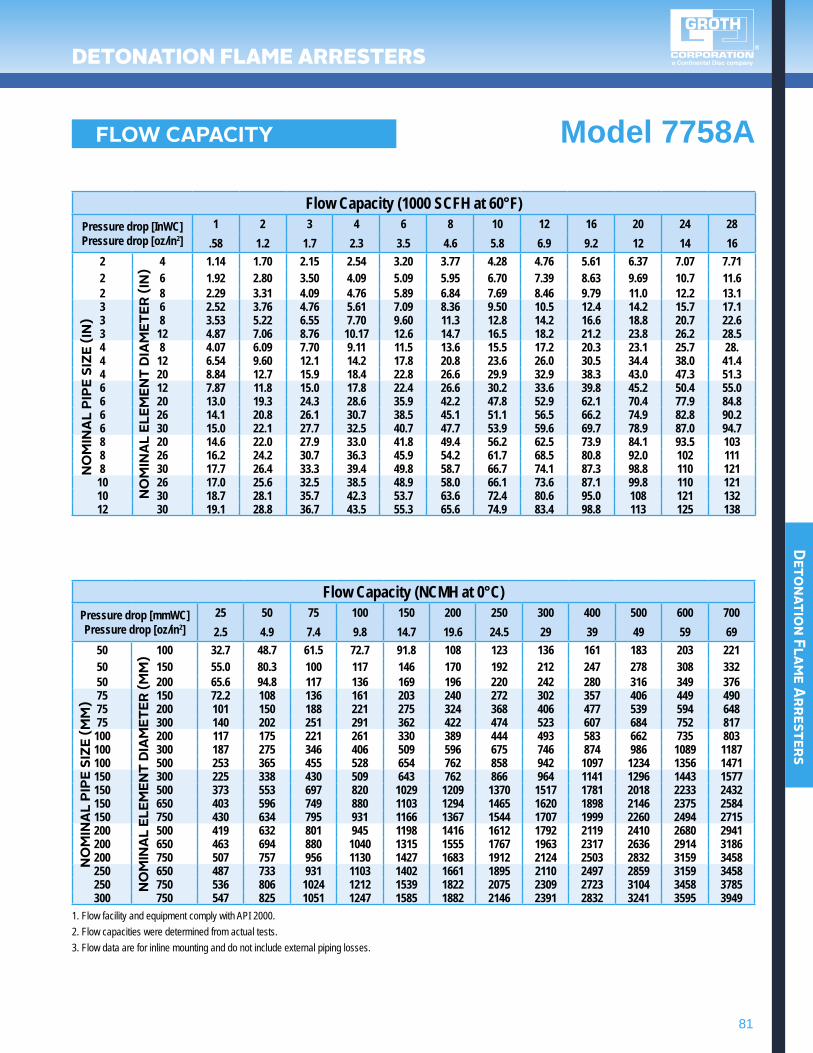
FLOw cAPAcITY Model 7758A
Flow Capacity (1000 SCFH at 60°F)Pressure drop [InWC]Pressure drop [oz/in2]
1 2 3 4 6 8 10 12 16 20 24 28.58 1.2 1.7 2.3 3.5 4.6 5.8 6.9 9.2 12 14 16
2 4 1.14 1.70 2.15 2.54 3.20 3.77 4.28 4.76 5.61 6.37 7.07 7.712 6 1.92 2.80 3.50 4.09 5.09 5.95 6.70 7.39 8.63 9.69 10.7 11.62 8 2.29 3.31 4.09 4.76 5.89 6.84 7.69 8.46 9.79 11.0 12.2 13.13 6 2.52 3.76 4.76 5.61 7.09 8.36 9.50 10.5 12.4 14.2 15.7 17.13 8 3.53 5.22 6.55 7.70 9.60 11.3 12.8 14.2 16.6 18.8 20.7 22.63 12 4.87 7.06 8.76 10.17 12.6 14.7 16.5 18.2 21.2 23.8 26.2 28.54 8 4.07 6.09 7.70 9.11 11.5 13.6 15.5 17.2 20.3 23.1 25.7 28.4 12 6.54 9.60 12.1 14.2 17.8 20.8 23.6 26.0 30.5 34.4 38.0 41.44 20 8.84 12.7 15.9 18.4 22.8 26.6 29.9 32.9 38.3 43.0 47.3 51.36 12 7.87 11.8 15.0 17.8 22.4 26.6 30.2 33.6 39.8 45.2 50.4 55.06 20 13.0 19.3 24.3 28.6 35.9 42.2 47.8 52.9 62.1 70.4 77.9 84.86 26 14.1 20.8 26.1 30.7 38.5 45.1 51.1 56.5 66.2 74.9 82.8 90.26 30 15.0 22.1 27.7 32.5 40.7 47.7 53.9 59.6 69.7 78.9 87.0 94.78 20 14.6 22.0 27.9 33.0 41.8 49.4 56.2 62.5 73.9 84.1 93.5 1038 26 16.2 24.2 30.7 36.3 45.9 54.2 61.7 68.5 80.8 92.0 102 1118 30 17.7 26.4 33.3 39.4 49.8 58.7 66.7 74.1 87.3 98.8 110 12110 26 17.0 25.6 32.5 38.5 48.9 58.0 66.1 73.6 87.1 99.8 110 12110 30 18.7 28.1 35.7 42.3 53.7 63.6 72.4 80.6 95.0 108 121 13212 30 19.1 28.8 36.7 43.5 55.3 65.6 74.9 83.4 98.8 113 125 138
Flow Capacity (NCMH at 0°C)Pressure drop [mmWC]Pressure drop [oz/in2]
25 50 75 100 150 200 250 300 400 500 600 7002.5 4.9 7.4 9.8 14.7 19.6 24.5 29 39 49 59 69
50 100 32.7 48.7 61.5 72.7 91.8 108 123 136 161 183 203 22150 150 55.0 80.3 100 117 146 170 192 212 247 278 308 33250 200 65.6 94.8 117 136 169 196 220 242 280 316 349 37675 150 72.2 108 136 161 203 240 272 302 357 406 449 49075 200 101 150 188 221 275 324 368 406 477 539 594 64875 300 140 202 251 291 362 422 474 523 607 684 752 817
100 200 117 175 221 261 330 389 444 493 583 662 735 803100 300 187 275 346 406 509 596 675 746 874 986 1089 1187100 500 253 365 455 528 654 762 858 942 1097 1234 1356 1471150 300 225 338 430 509 643 762 866 964 1141 1296 1443 1577150 500 373 553 697 820 1029 1209 1370 1517 1781 2018 2233 2432150 650 403 596 749 880 1103 1294 1465 1620 1898 2146 2375 2584150 750 430 634 795 931 1166 1367 1544 1707 1999 2260 2494 2715200 500 419 632 801 945 1198 1416 1612 1792 2119 2410 2680 2941200 650 463 694 880 1040 1315 1555 1767 1963 2317 2636 2914 3186200 750 507 757 956 1130 1427 1683 1912 2124 2503 2832 3159 3458250 650 487 733 931 1103 1402 1661 1895 2110 2497 2859 3159 3458250 750 536 806 1024 1212 1539 1822 2075 2309 2723 3104 3458 3785300 750 547 825 1051 1247 1585 1882 2146 2391 2832 3241 3595 3949
NO
MIN
AL
PIPE
SIZ
E (IN
)N
OM
INA
L PI
PE S
IZE
(MM
)
NO
MIN
AL
ELEM
ENT
DIA
MET
ER (I
N)
NO
MIN
AL
ELEM
ENT
DIA
MET
ER (M
M)
1. Flow facility and equipment comply with API 2000.2. Flow capacities were determined from actual tests.3. Flow data are for inline mounting and do not include external piping losses.